

Page 1

(ZW-7000 series)
CJ Series
EtherNet/IP
Connection Guide
OMRON Corporation
Displacement Sensor
TM
P661-E1-01
Page 2

About Intellectual Property Rights and Trademarks
Microsoft product screen shots reprinted with permission from Microsoft Corporation.
Windows is a registered trademark of Microsoft Corporation in the USA and other countries.
ODVA and EtherNet/IP
TM
are trademarks of ODVA.
Company names and product names in this document are t he trademarks or registered
trademarks of their respective companies.
Page 3

Table of Contents
1. Related Manuals ........................................................................................ 1
2. Terms and Definitions ............................................................................... 2
3. Precautions ................................................................................................ 3
4. Overview .................................................................................................... 4
5. Applicable Devices and Device Configuration ....................................... 5
5.1. Applicable Devices ............................................................................. 5
5.2. Device Configuration .......................................................................... 6
6. EtherNet/IP Settings .................................................................................. 8
6.1. Parameters ........................................................................................ 8
6.2. Tag Data Link Settings ....................................................................... 9
7. EtherNet/IP Connection Procedure ........................................................ 12
7.1. Work Flow ........................................................................................ 12
7.2. Sensor Controller Setup ................................................................... 14
7.3. PLC Setup ........................................................................................ 25
7.4. Network Settings .............................................................................. 35
7.5. EtherNet/IP Communication Status Check ...................................... 48
8. Initialization method ................................................................................ 55
8.1. Initializing PLC ................................................................................. 55
8.2. Initializing Sensor Controller ............................................................ 56
9. Revision History ...................................................................................... 57
Page 4

1.Related Manuals
1
1. Related Manuals
To ensure system safety, make sure to always read and follow the information provided in all
Safety Precautions and Precautions for Saf e Use in the manuals for each device which is
used in the system.
Cat. No. Model Manual name
W472 CJ2M-CPU[][]
CJ2H-CPU6[]
CJ2H-CPU6[]-EIP
W473 CJ2M-CPU[][]
CJ2H-CPU6[]
CJ2H-CPU6[]-EIP
W465 CJ1W-EIP21
CJ2M-CPU3[]
CJ2H-CPU6[]-EIP
W446 CXONE-AL[][]C-V4
/ AL[][]D-V4
0969584-7 W4S1-05[]
W4S1-03B
Z362 ZW-7000[] Displacement Sensor ZW-7000 series
Z363 ZW-7000[] Displacement Sensor ZW-7000 series
CJ-series
CJ2 CPU Unit
Hardware USER'S MANUAL
CJ-series
CJ2 CPU Unit
Software USER'S MANUAL
CJ Series
EtherNet/IP
OPERATION MANUAL
CX-Programmer
OPERATION MANUAL
Switching Hub
W4S1-series
Users Manual
Confocal Fiber Type
Displacement Sensor User’s Manual
Confocal Fiber Type Displacement
Sensor User’s Manual for
Communications Settings
TM
Units
Page 5

2.Terms and Definitions
2
network.
address, and it is assigned to the memory area of each device.
Corporation.
This standard feature on EtherNet/IP is called a tag data link .
between the specified nodes concurrently.
than one node.
and the node that receives the request is called a "target " .
parameter
It includes the data to set tags, tag sets, and connect ions.
and the parameters that can be set via EtherNet/IP.
2. Terms and Definitions
Term Explanation and Definition
Node A programmable controller and a device are connected to an EtherNet/IP
network via EtherNet/IP ports. EtherNet/IP recognizes each EtherNet/IP
port connected to the network as one node.
When a device with two EtherNet/IP ports is connected to the
EtherNet/IP network, EtherNet/IP recognizes this device as two nodes.
EtherNet/IP achieves the communications between programmable
controllers or the communications between a pro grammable controller
and a device by exchanging data between these nodes connected to the
Tag A minimum unit of the data that is exchanged on the EtherNet/IP network
is called a tag. The tag is defined as a network variable or as a physical
Tag set In the EtherNet/IP network, a data unit that consists of two or more tags
can be exchanged. The data unit consisting of two or more tags f or the
data exchange is called a tag set. Up to eight tags can be confi gured per
tag set for the programmable controllers produced by OMRON
Tag data link In EtherNet/IP, the tag and tag set can be exchanged cyclically between
nodes without using a user program.
Connection A connection is used to exchange data as a unit within which data
concurrency is maintained. The connection consists of tags or tag sets.
Creating the concurrent tag data link between the specified nodes is
called a "connection establishment". When the connection is established,
the tags or tag sets that configure the connection are excha nged
Connection type There are two kinds of connection types for the tag data li nk connection.
One is a multi-cast connection, and the other is a unicast (point-to-point)
connection. The multi-cast connection sends an output tag set in one
packet to more than one node. The unicast connection separately sends
one output tag set to each node. Therefore, multi-cast connections can
decrease the communications load if one output tag set is sent to more
Originator and
Target
To operate tag data links, one node requests the opening of a
communications line called a "connection".
The node that requests to open the connection is cal led an "originator",
Tag data link
EDS file A file that describes the number of I/O points for the EtherNet/IP device
A tag data link parameter is the setting data to operate tag data links.
Page 6
3.Precautions
3
Precautions for Correct Use
Additional Information
Symbol
3. Precautions
(1) Understand the specifications of devices which are used in the system. Allow some
margin for ratings and performance. Provide saf ety measures, such as installing a safety
circuit, in order to ensure safety and minimize the risk of abnormal occurrence.
(2) To ensure system safety, make sure to always read and follow the information provided in
all Safety Precautions and Precautions for Safe Use in the manuals for each device
which is used in the system.
(3) The user is encouraged to confirm the standards and regulations that the system must
conform to.
(4) It is prohibited to copy, to reproduce, and to distribute a part or the whole of this
document without the permission of OMRON Corporat ion.
(5) The information contained in this document is current as of July 2016. It is subject to
change for improvement without notice.
The following notations are used in this docum ent.
Indicates a potentially hazardous situation whi ch, if not avoided,
may result in minor or moderate injury or property damage.
Precautions on what to do and what not to do to ensure proper operation and performance.
Additional information to read as required.
This information is provided to increase unders tanding or make operation easier.
The triangle symbol indicates precautions (including warnings).
The specific operation is shown in the triangle and explained in the text.
This example indicates a general precaution.
Page 7

4.Overview
4
4. Overview
This document describes the procedures f or connecting Displacement Sensor (hereinafter
referred to as Sensor Controller) to CJ-seri es Programmable Controller + EtherNet/IP Unit
(hereinafter referred to as PLC) via EtherNet/ IP, both produced by OMRON Corporation
(hereinafter referred to as OMRON), and for check ing their connections.
Refer to Section 6. EtherNet/IP Settings and Section 7. EtherNet/IP Connection Procedure to
understand setting methods and key points to operate EtherNet/IP tag data links.
In this document, CJ-series EtherNet/IP Unit and the built-in EtherNet/IP port of CJ-series CJ2
CPU Unit are collectively called as "EtherNet/IP Unit''.
Page 8

5.Applicable Devices and Device Configuration
5
Additional Information
5. Applicable Devices and Device Configuration
5.1. Applicable Devices
The applicable devices are as follows:
Manufacturer Name Model
OMRON CJ2 CPU Unit CJ2[]-CPU[][]
OMRON EtherNet/IP Unit CJ1W-EIP21
CJ2H-CPU6[]-EIP
CJ2M-CPU3[]
OMRON Confocal Fiber Type
Displacement Sensor
Sensor Controller
Sensor Head
ZW-7000[]
ZW-S70[][]
Precautions for Correct Use
In this document, the devices with models and versions listed in 5.2. Device Configuration are
used as examples of applicable devices to des cribe the procedures for connecting the
devices and checking their connections.
You cannot use devices with versions lower than the versions list ed in 5.2.
To use the above devices with models not listed in 5.2. or versions higher than thos e listed in
5.2., check the differences in the specifications by referring to t he manuals before operating
the devices.
This document describes the procedures f or establishing the network connections.
It does not provide information on operation, installation, wiring method, device functional it y,
or device operation, which is not related to the connection procedures.
Refer to the manuals or contact the device manufac turer.
Page 9
5.Applicable Devices and Device Configuration
6
Manufacturer
Name
Model
Version
OMRON
CJ2 CPU Unit
(Built-in EtherNet/IP port)
CJ2M-CPU32
Ver.2.0
(Ver.2.12)
OMRON
Power Supply Unit
CJ1W-PA202
OMRON
Switching hub
W4S1-05C
Ver.1.00
-
24 VDC power supply
-
OMRON
CX-One
CXONE-AL[][]C-V4
/AL[][]D-V4
Ver.4.[][]
OMRON
CX-Programmer
(Included in CX-One)
Ver.9.61
OMRON
Network Configurator
(Included in CX-One)
Ver.3.59c
-
Personal computer
(OS: Windows 7)
-
-
USB cable
(USB 2.0 type B connector)
-
-
LAN cable (STP (shielded,
category 5 or higher)
-
OMRON
S8VS-06024
Precautions for Correct Use
ZW-7000
24 VDC power supply
Calibration ROM
CJ2M-CPU32
Personal computer
24 VDC power supply
LAN cable
W4S1-05C
5.2. Device Configuration
The hardware components to reproduce the connect i on procedures in this document are as
follows:
(CX-One installed,
OS: Windows 7)
USB cable
(Built-in EtherNet/IP port)
(for Sensor Controller)
(for Switching hub)
twisted-pair) cable of Ethernet
OMRON Sensor Controller ZW-7000 Ver.2.020
OMRON Sensor Head ZW-S7030
OMRON Calibration ROM (Supplied with Sensor Head)
24 VDC power supply (for Sensor
Controller) (24 VDC, 2.5A, 60W)
Update CX-Programmer and Network Configurator to the version specified in this Clause 5.2.
or to a higher version. If you use a version higher than the one specified, the procedures and
related screenshots described in Section 7. and subsequent sections may not be applicable.
In that case, use the equivalent procedures described i n this document by referring the
CX-Programmer OPERATION MANUAL (Cat. No. W446) and Network Configurator Online
Help.
Page 10

7
Additional Information
Additional Information
For specifications of 24 VDC power supply available for Switching hub, refer to the Switching
Hub W4S1-series Users Manual (Cat. No. 0969584-7).
For specifications of 24 VDC power supply available for Sensor Controller, refer to the
Displacement Sensor ZW-7000 series Confocal Fiber Type Displacement Sensor User ’s
Manual (Cat. No. Z362).
Additional Information
The system configuration in this document uses USB for the connection between Personal
computer and PLC. For information on how to install the USB driver, refer to A-5 Installing the
USB Driver of the CJ-series CJ2 CPU Unit Hardware Us er's Manual (Cat. No. W472).
5.Applicable Devices and Device Configuration
Page 11

6.EtherNet/IP Settings
8
6. EtherNet/IP Settings
This section describes the contents of parameter and tag data link settings that are all defined
in this document.
6.1. Parameters
The parameters required for connecting PLC to Sensor Controller via EtherNet/IP are shown
below.
Item PLC (Node 1) Sensor Controller (Node 50)
IP address 192.168.250.1 192.168.250.50
Subnet mask 255.255.255.0 255.255.255.0
Fieldbus - EtherNet/IP
Page 12
6.EtherNet/IP Settings
9
Address
Bit
Function name
Sensor head control signal 1 (lower 16 bits)
0 Control command execution
1 to 15
Reserved
Sensor head control signal 1 (upper 16 bits)
0 Error clear
1 to 15
Reserved
Sensor head control signal 2 (lower 16 bits)
0 Timing
1 Reset
2 Light metering OFF
4 to 15
Reserved
Sensor head control signal 2 (upper 16 bits)
0 TASK1 Zero reset execution
1 TASK2 Zero reset execution
2 TASK3 Zero reset execution
3 TASK4 Zero reset execution
4 TASK1 Zero reset cancel
5 TASK2 Zero reset cancel
6 TASK3 Zero reset cancel
7 TASK4 Zero reset cancel
8 to 15
Reserved
D10004
0 to 15
Extended area (lower 16 bits)
D10005
0 to 15
Extended area (upper 16 bits)
D10006
0 to 15
Command code (lower 16 bits)
D10007
0 to 15
Command code (upper 16 bits)
D10008
0 to 15
Command parameter 1
D10009
0 to 15
Command parameter 2
D10010
0 to 15
Command parameter 3 (lower 16 bits)
D10011
0 to 15
Command parameter 4 (upper 16 bits)
6.2. Tag Data Link Settings
The following shows the content of tag data link settings for Sensor Controller.
Output area Input area
D10000
(PLC to Sensor Controller)
24 bytes
D10011
■Output area
D10000
D10001
D10100
(Sensor Controller to PLC)
56 bytes
D10127
D10002
D10003
Page 13
10
■Input area
Address
Bit
Function name
0 Control command completion
1 Reserved
2 Ready
3 Reserved
4 Run screen
5 to 10
Reserved
11 Current bank number bit0
12 Current bank number bit1
13 Current bank number bit2
14 Current bank number bit3
15 Current bank number bit4
0 Error
1 to 15
Reserved
Sensor head status signal 2 (lower 16 bits)
0 Hold execution status
1 Reset execution state
2 Logical beam lighting state
3 Measurement position
4 Measurement state
5 Data output completed
6 Overall judgment result
7 Reserved
8 TASK1 TASK status
9 TASK2 TASK status
10 TASK3 TASK status
11 TASK4 TASK status
12 to 15
Reserved
Sensor head status signal 2 (upper 16 bits)
0 TASK1 Zero reset state
1 TASK2 Zero reset state
2 TASK3 Zero reset state
3 TASK4 Zero reset state
4 TASK1 HIGH output
5 TASK1 PASS output
6 TASK1 LOW output
7 TASK2 HIGH output
8 TASK2 PASS output
9 TASK2 LOW output
10 TASK3 HIGH output
11 TASK3 PASS output
12 TASK3 LOW output
13 TASK4 HIGH output
14 TASK4 PASS output
15 TASK4 LOW output
D10100
D10101
6.EtherNet/IP Settings
Sensor head status signal 1 (lower 16 bits)
Sensor head status signal 1 (upper 16 bits)
D10102
D10103
Page 14

6.EtherNet/IP Settings
11
Address
Bit
Function name
D10104
0 to 15
Extended area (lower 16 bits)
D10105
0 to 15
Extended area (upper 16 bits)
D10106
0 to 15
Command code echo (lower 16 bits)
D10107
0 to 15
Command code echo (upper 16 bits)
D10108
0 to 15
Response code (lower 16 bits)
D10109
0 to 15
Response code (upper 16 bits)
D10110
0 to 15
Response data (lower 16 bits)
D10111
0 to 15
Response data (upper 16 bits)
D10112
0 to 15
Output data 0 (lower 16 bits)
D10113
0 to 15
Output data 0 (upper 16 bits)
D10114
0 to 15
Output data 1 (lower 16 bits)
D10115
0 to 15
Output data 1 (upper 16 bits)
D10116
0 to 15
Output data 2 (lower 16 bits)
D10117
0 to 15
Output data 2 (upper 16 bits)
D10118
0 to 15
Output data 3 (lower 16 bits)
D10119
0 to 15
Output data 3 (upper 16 bits)
D10120
0 to 15
D10121
0 to 15
D10122
0 to 15
D10123
0 to 15
D10124
0 to 15
D10125
0 to 15
D10126
0 to 15
D10127
0 to 15
Reserved
Page 15

7.EtherNet/IP Connection Procedure
12
7.2. Sensor Controller Setup
Set up Sensor Controller.
7.2.1. Hardware Settings
Connect cables and others to Sensor Controller.
Set the parameters for Sensor Controller.
7.3. PLC Setup
Set up PLC.
Set the hardware switches on EtherNet/IP Unit and
wire the network.
Start CX-Programmer and connect online with
Create the I/O table and set the IP address of PLC.
7.4. Network Settings
Set the EtherNet/IP tag data links.
Start Network Configurator and connect onli ne wi th
Upload the network configuration.
Register tags for input (consume) and output
(produce).
7. EtherNet/IP Connection Procedure
This section describes the procedures for connecting PLC and Sensor Controller on the
EtherNet/IP network.
The explanations of procedures for setting up PLC and Sensor Controller given in this
document are based on the factory default settings.
For the initialization, refer to Section 8. Initialization Method.
7.1. Work Flow
Take the following steps to operate tag data links by connecting PLC and Sensor Contr oller
via EtherNet/IP.
↓
↓
7.2.2. Parameter Settings
↓
↓
7.3.1. Hardware Settings
↓
7.3.2. Starting CX-Programmer and
Connecting Online with PLC
↓
7.3.3. Creating the I/O Table and
Setting the IP Address
↓
↓
PLC.
7.4.1. Starting Network Configurator
and Connecting Online with
PLC
↓
7.4.2. Uploading the Network
Configuration
↓
7.4.3. Setting the Tags
↓
PLC.
Page 16

13
Associate the tags of the target device with the
tags of the originator device.
Transfer the set tag data link parameters to PLC.
Check
Confirm that the EtherNet/IP tag data links operate
Check the connection status of the EtherNet/IP
network.
Check that the correct data are sent and received.
7.4.4. Setting the Connections
7.EtherNet/IP Connection Procedure
↓
7.4.5. Transferring the Tag Data Link
Parameters
↓
7.5. EtherNet/IP Communication Status
↓
7.5.1. Checking the Connection Status
↓
7.5.2. Checking the Sent and
Received Data
normally.
Page 17
14
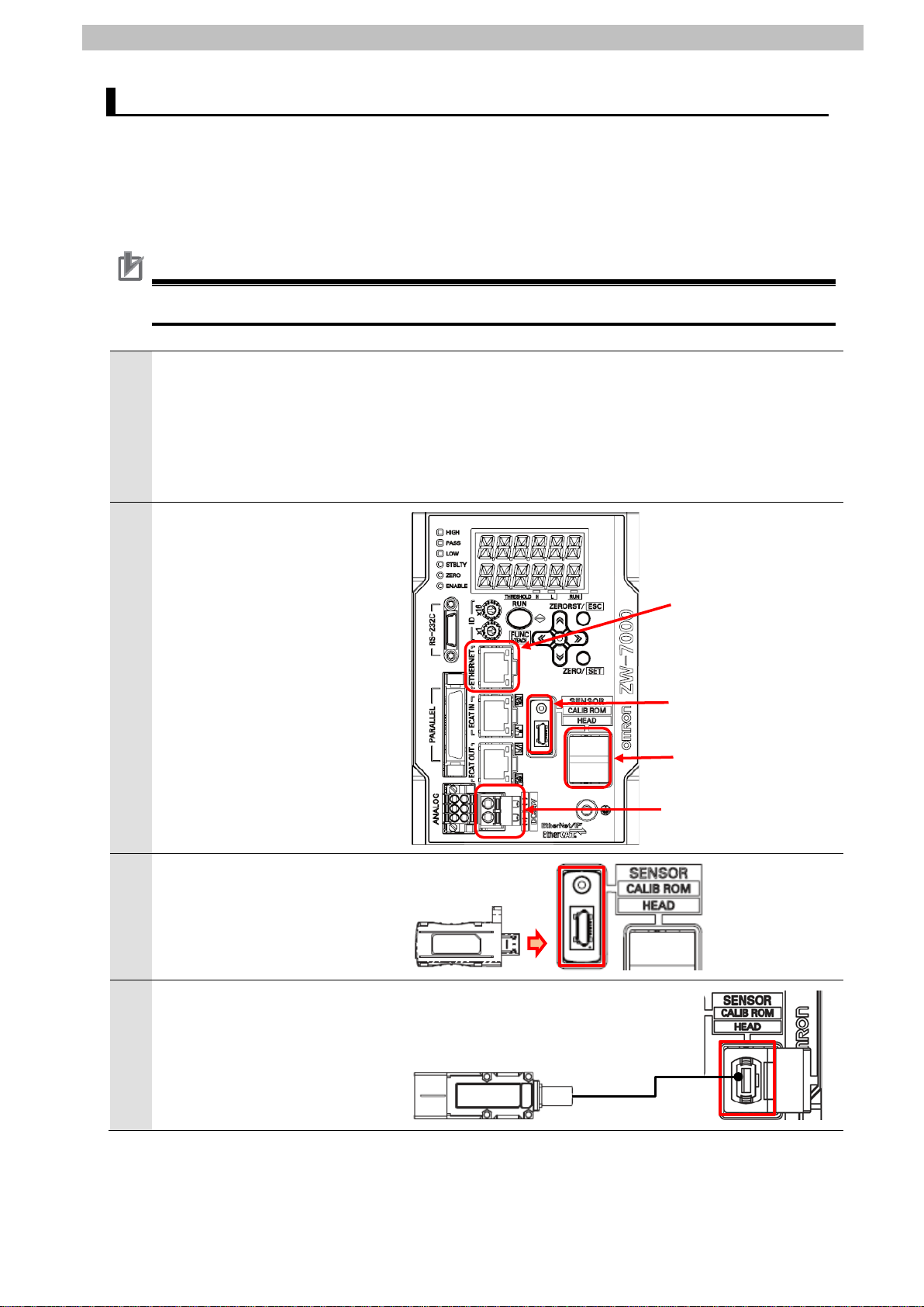
7.2. Sensor Controller Setup
1
may not be applicable.
3
connector
block
Set up Sensor Controller.
7.2.1. Hardware Settings
Connect cables and others to Sensor Controller.
Precautions for Correct Use
Make sure that the power supply is OFF when you set up.
Make sure that Sensor
Controller is powered OFF.
*If it is ON, the settings
described in the following steps
and subsequent procedures
7.EtherNet/IP Connection Procedure
Check the position of
2
connectors on Sensor Controller
by referring to the figure on the
right.
Connect the calibration ROM to
ROM connector.
Ethernet
ROM connector
Fiber adapter
24V input terminal
4
Connect Fiber connector on
Sensor Head to Fiber adapter.
Page 18
7.EtherNet/IP Connection Procedure
15
24 VDC power supply
6
Manual (Cat. No. Z362).
Connect Switching hub and
5
Ethernet connector on Sensor
Controller with a LAN cable.
Connect 24 VDC power supply
(for Switching hub) to Switching
hub.
Connect 24 VDC power supply
to 24 V input terminal block.
*For details on specifications of
24 VDC power supply available
for Sensor Controller, refer to
the Displacement
SensorZW-7000 series
Confocal Fiber Type
Displacement Sensor User’s
LAN cable
24 VDC power supply
Page 19
16
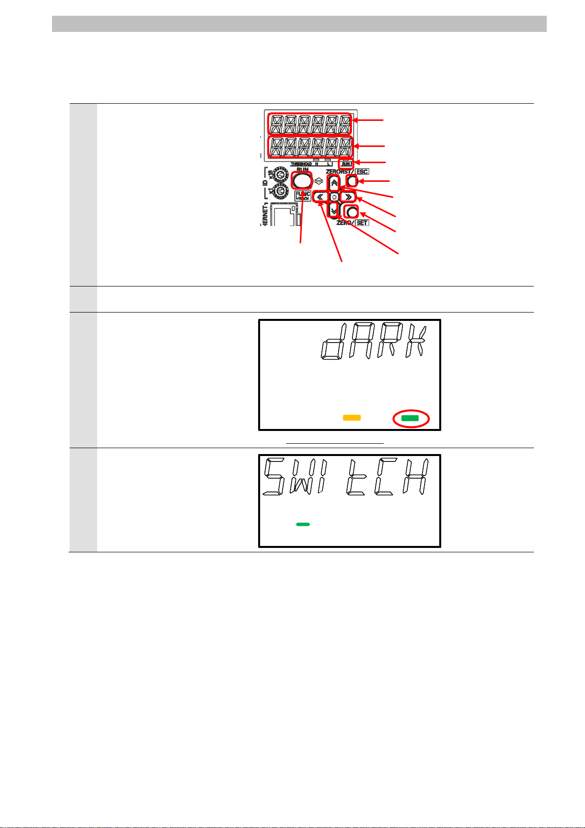
7.2.2. Parameter Settings
1
2
3
4
0kzcan
RUN Indicator (Green)
ZERORST/ESC Key
ZERO/SET Key
(DOWN) Key
↑(UP) Key
(RIGHT) Key
(LEFT) Key
Mode Switching
Set the parameters for Sensor Controller.
Check the positions of each key
and displays to use for
parameter settings.
7.EtherNet/IP Connection Procedure
Main Display (White)
Sub-display (Green)
Turn ON Sensor Controller.
The system enters the RUN
mode after displaying “INIT” for
a few seconds.
*The RUN Indicator is lit in the
RUN mode.
Press and hold the Mode
Switching Key for two seconds.
OK/CAN is displayed.
Press the ZERO/SET Key.
Key
←
*5000
THRESHOLD H L RUN
→
↓
Page 20

17
The operation mode is switched
←
6
←
7
→
5
to the FUNC mode, and SENS
is displayed on Main Display.
*The RUN Indicator goes out in
the FUNC mode.
Keep pressing the →(RIGHT)
or the
(LEFT) Keys until
SYSTEM is displayed.
Press the ZERO/SET Key.
H.CALIB is displayed on Main
Display.
Keep pressing the →(RIGHT )
or the
(LEFT) Keys until
COM is displayed.
Press the ZERO/SET Key.
7.EtherNet/IP Connection Procedure
THRESHOLD H L RUN
RS232C is displayed on Main
Display.
Change the menu from RS232C
to ETN by pressing the
(RIGHT ) Key.
Press the ZERO/SET Key.
Page 21

18
9
→
↑
IPADDR is displayed on Main
8
Display.
Press the ZERO/SET Key.
IP1 is displayed on Main
Display.
Press the ZERO/SET Key.
Check that 192 is displayed on
Sub-display.
*The set value here is the first
octet "192" of the IP address
192.168.250.50.
*If the value is different, press
the ZERO/SET Key.
The Sub-display changes to
the editing mode that enables
you to edit the value.
An editable digit of the value
blinks.
Select the digit you want to
change by pressing the
(RIGHT ) or the ←(LEFT)
Keys.
Change the value by pressing
the
Keys.
Press the ZERO/SET Key
again to fix the set value.
Press the ZERORST/ESC Key.
The first menu shown in this
step is displayed again
Press the →(RIGHT ) Key.
(UP) or the ↓(DOWN)
7.EtherNet/IP Connection Procedure
192
000192
192
Page 22

7.EtherNet/IP Connection Procedure
19
11
10
IP2 is displayed on Main
Display.
Press the ZERO/SET Key.
Check that 168 is displayed on
Sub-display.
*The set value here is the
second octet "168" of the IP
address 192.168.250.50.
*If the value is different, change
the value in the same way as
step 9.
Press the ZERORST/ESC Key.
The first menu shown in this
step is displayed again.
Press the →(RIGHT ) Key.
168
IP3 is displayed on Main
Display.
Press the ZERO/SET Key.
Check that 250 is displayed on
Sub-display.
*The set value here is the third
octet "250" of the IP address
192.168.250.50.
*If the value is different, change
the value in the same way as
step 9.
Press the ZERORST/ESC Key.
The first menu shown in this
step is displayed again.
Press the →(RIGHT ) Key.
250
Page 23

7.EtherNet/IP Connection Procedure
20
13
→
12
IP4 is displayed on Main
Display.
Press the ZERO/SET Key.
Check that 50 is displayed on
Sub-display.
*The set value here is the fourth
octet "50" of the IP address
192.168.250.50.
*If the value is different, change
the value in the same way as
step 9.
Press the ZERORST/ESC Key.
The first menu shown in this
step is displayed again.
Press the ZERORST/ESC Key.
50
IPADDR is displayed on Main
Display.
Change the menu to SUBNET
by pressing the
Press the ZERO/SET Key.
(RIGHT) Key.
Page 24

7.EtherNet/IP Connection Procedure
21
14
SUB1 is displayed on Main
Display.
Press the ZERO/SET Key.
Check that 255 is displayed on
Sub-display.
*The set value here is the first
octet "255" of the subnet mask
255.255.255.0.
*If the value is different, change
the value in the same way as
step 9.
Press the ZERORST/ESC Key.
The first menu shown in this
step is displayed again.
Press the →(RIGHT ) Key.
255
15
SUB2 is displayed on Main
Display.
Press the ZERO/SET Key.
Check that 255 is displayed on
Sub-display.
*The set value here is the
second octet "255" of the
subnet mask 255.255.255.0.
*If the value is different, change
the value in the same way as
step 9.
Press the ZERORST/ESC Key.
The first menu shown in this
step is displayed again.
Press the →(RIGHT ) Key.
255
Page 25

7.EtherNet/IP Connection Procedure
22
16
SUB3 is displayed on Main
Display.
Press the ZERO/SET Key.
Check that 255 is displayed on
Sub-display.
*The set value here is the third
octet "255" of the subnet mask
255.255.255.0.
*If the value is different, change
the value in the same way as
step 9.
Press the ZERORST/ESC Key.
The first menu shown in this
step is displayed again.
Press the →(RIGHT ) Key.
255
17
SUB4 is displayed on Main
Display.
Press the ZERO/SET Key.
Check that 0 is displayed on
Sub-display.
*The set value here is the fourth
octet "0" of the subnet mask
255.255.255.0.
*If the value is different, change
the value in the same way as
step 9.
Press the ZERORST/ESC Key.
The first menu shown in this
step is displayed again.
Press the ZERORST/ESC Key
twice.
0
Page 26

7.EtherNet/IP Connection Procedure
23
→
19
Switching
18
ETN is displayed on Main
Display.
Change the menu to MEMLNK
by pressing the
twice.
Press the ZERO/SET Key.
E-CAT is displayed on
Sub-display.
Press the ↑(UP) Key to
change the menu to EIP in
blinking.
EIP stops blinking when
pressing the ZERO/SET Key.
*The memory link function is set
to EtherNet/IP.
Press and hold the Mode
Key for two seconds.
(RIGHT) Key
e-cat
elp
Page 27

7.EtherNet/IP Connection Procedure
24
21
22
valid after power cycling.
20
OK/CAN is displayed.
Press the ZERO/SET Key.
SAVE is displayed on Main
Display.
Press the ZERO/SET Key.
The operation mode is switched
to the RUN mode.
0kzcan
0kzcan
*5000
THRESHOLD H L RUN
Power cycle Sensor Controller.
*The saved setting data become
Page 28

7.EtherNet/IP Connection Procedure
25
1
applicable.
2
3
The unit number is used to identify individual CPU Bus Units when more than
4
switches.
With the FINS communications service, when there are multiple EtherNet/IP
7.3. PLC Setup
Set up PLC.
7.3.1. Hardware Settings
Set the hardware switches on EtherNet/IP Unit and wire the network.
Precautions for Correct Use
Make sure that the power supply is OFF when you set up.
Make sure that PLC and
Switching hub are powered
OFF.
*If either of them is ON, the
settings described in the
following steps and subsequent
procedures may not be
Check the position of the
hardware switches on the front
panel of EtherNet/IP Unit by
referring to the figure on the
right.
Set Unit number setting switch
to 0.
Set Node address setting
switches to the following default
settings.
NODE No.x16
NODE No.x16
1
0
: 0
: 1
*The IP address is set to
192.168.250.1.
one CPU Bus Unit is mounted to the same PLC. Use a small screwdriver to
make the setting, taking care not to damage the rotary switch. The unit
number is factory-set to 0.
Units connected to the Ethernet network, the EtherNet/IP Units are identified
by node addresses. Use the node address switches to set the node address
between 01 and FE hexadecimal (1 to 254 decimal).Do not set a number that
has already been set for another node on the same network.
The left switch sets the sixteens digit (most significant digit) and the right
switch sets the ones digit (least significant digit).The node address is
factory-set to 01.
Default IP address = 192.168.250.node address
With the factory-default node address setting of 01, the default IP address is
192.168.250.1.
*By default, the first to third
octets of the local IP address
are fixed to 192.168.250. The
fourth octet is a value that is set
with Node address setting
Page 29

7.EtherNet/IP Connection Procedure
26
6
hub.
7
Personal
24 VDC power supply
LAN cable
PLC
Power Supply Unit
Switching hub
CPU Unit
Connect a LAN cable to the
5
EtherNet/IP port on PLC, and
connect a USB cable to the USB
port. As shown in 5.2. Device
Configuration, connect Personal
computer and Switching Hub to
PLC.
Turn ON PLC and Switching
The set IP address is displayed
on the seven-segment LED
indicators. Afterwards, the last
digit of the IP address is
displayed in hexadecimal during
normal operation.
computer
USB cable
Page 30

7.EtherNet/IP Connection Procedure
27
1
CX-Programmer.
2
3
4
7.3.2. Starting CX-Programmer and Connecting Online with PLC
Start CX-Programmer and connect online with PLC.
Install CX-One and the USB driver on Personal computer beforehand.
Start CX-Programmer.
*If the User Account Control
Dialog Box is displayed at start,
make a selection to start
CX-Programmer starts.
Select Auto Online - Direct
Online from the PLC Menu.
The Direct Online Dialog Box is
displayed.
Select USB connection as
Connection Type.
Click Connect.
Page 31

28
The dialog box on the right is
6
7
during online connection.
Additional Information
Additional Information
5
displayed. Check the contents
and click No.
The dialog box on the right is
displayed.
CX-Programmer and PLC are
automatically connected.
Check that CX-Programmer and
PLC are normally connected
online.
7.EtherNet/IP Connection Procedure
*The icon is press ed down
If PLC cannot be connected online, check the cable c onnection.
Or, return to step 1, check the settings and repeat each step.
For details, refer to Connecting Directly to a CJ2 CPU Unit Using a USB Cable of the
CX-Programmer OPERATION MANUAL (Cat. No. W446).
The dialog boxes explained in the following procedures may not be displayed depending on
the environmental settings of CX-Programmer.
For details on the environmental settings, refer to Options and Preferences in CHAPTER 3
Project Reference in PART 1: CX-Programmer of the CX-Programmer OPERATION
MANUAL (Cat. No. W446). This document explains the setting procedures when ''Confirm all
operations affecting the PLC'' is selected.
Page 32

7.EtherNet/IP Connection Procedure
29
1
2
7.3.3. Creating the I/O Table and Setting the IP Address
Create the I/O table and set the IP address of PLC.
If the operating mode of PLC is
Run Mode or Monitor Mode,
change it to Program Mode by
following the steps below.
(1)Select Operating Mode -
Program from the PLC
Menu in CX-Programmer.
(2)The dialog box on the right is
displayed. Confirm that there
is no problem, and click Yes.
*Refer to Additional Information
on the previous page for the
settings concerning the dialog
display.
(3)Check that Stop/Program
Mode is displayed on the
right of the PLC model in the
Project Workspace of
CX-Programmer.
Select Edit - I/O Table and Unit
Setup from the PLC Menu in
CX-Programmer.
The PLC IO Table Window is
displayed.
(Project Workspace)
Page 33

7.EtherNet/IP Connection Procedure
30
Precautions for Correct Use
3
The PLC is reset after creating and transferring the I/O table in step 3 and subsequent steps.
Always confirm safety before creating and transferring the I/O table.
Select Create from the Options
Menu in the PLC IO Table
Window.
The dialog box on the right is
displayed. Confirm that there is
no problem, and click Yes.
The dialog box on the right is
displayed. Confirm that there is
no problem, and click Yes.
Page 34

7.EtherNet/IP Connection Procedure
31
The Transfer from PLC Dialog
4
Box is displayed.
Select IO Table and SIO Unit
Parameters.
Click Transfer.
When the transfer is completed,
the Transfer Results Dialog Box
is displayed.
Check that the transfer is
successfully completed by
referring to the message in the
dialog box.
When the I/O table is created
normally, the dialog box displays
as follows:
Transfer Success: 1 Unit
Transfer Unsuccessful: 0 Unit
Click OK.
Page 35

32
In the PLC IO Tabl e Window,
5
click + to the left of Built-in
Port/Inner Board to display
CJ2M-EIP21.
*The figure on the right displays
CPU Unit (Built-in EtherNet/IP
port) specified in 5.2. Device
Configuration. If you use an
other applicable EtherNet/IP
Unit, the display position and
name are different from the
figure on the right.
Right-click CJ2M-EIP21 and
select Unit Setup.
7.EtherNet/IP Connection Procedure
The Edit Parameters Dialog Box
6
is displayed.
Select the TCP/IP Tab.
Make the following settings in
the IP Address Field.
・Use the following address:
Select
・IP address: 192.168.250.1
・Subnet mask: 255.255.255.0
Click Transfer[PC to Unit].
Page 36

33
The dialog box on the right is
8
7
displayed. Confirm that there is
no problem, and click Yes.
Check that a message is
displayed stating "Transfer
successful". Click Close.
7.EtherNet/IP Connection Procedure
The dialog box on the right is
displayed. Check the contents
and click Yes.
When the Unit is restarted, the
dialog box on the right is
displayed. Check the contents
and click OK.
Page 37

34
Click Compare to check that the
10
11
9
IP address is correctly changed.
Check that a message is
displayed stating "Compare
successful". Click Close.
7.EtherNet/IP Connection Procedure
Click OK in the Edit Parameters
Dialog Box.
Page 38

7.EtherNet/IP Connection Procedure
35
1
2
7.4. Network Settings
Set the EtherNet/IP tag data links.
7.4.1. Starting Network Configurator and Connecting Online with PLC
Start Network Configurator and connect onli ne wi th PLC.
Right-click CJ2M-EIP21 in the
PLC IO Table Window, and
select Start Special
Application - Start with
Settings Inherited.
The Select Special Application
Dialog Box is displayed.
Select Network Configurator and
click OK.
Network Configurator starts.
Page 39

7.EtherNet/IP Connection Procedure
36
Precautions for Correct Use
3
4
6
Check that the LAN cables are connected before performing the following steps.
If they are not connected, turn OFF each of the devices, and then connect the LAN cables.
Select Select Interface - CJ2
USB/Serial Port from the
Option Menu.
Select Connect from the
Network Menu.
The Setup Interface Dialog Box
5
is displayed,
Check that the following settings
are made.
Port Type: USB
Port: OMR0
Baud Rate: 115200 Bit/s
Click OK.
The Select Connect Network
Port Dialog Box is displayed.
Select BackPlane CJ2M-EIP21 - TCP:2.
Click OK.
Page 40

37
The Select Connected Network
8
7
Dialog Box is displayed.
Check the contents and click
OK.
When an online connection is
established normally, the color
of the icon changes to blue as
shown on the right.
7.EtherNet/IP Connection Procedure
Additional Information
If PLC cannot be connected online, check the cable c onnection.
Or, return to step 3, check the settings and repeat each step.
For details, refer to 6-2-9 Connecting the Network Configurator to the Network in SECTION 6
Tag Data Link Functions of the EtherNet/IP
TM
Units OPERATION MANUAL (Cat. No. W465).
Page 41

7.EtherNet/IP Connection Procedure
38
1
3
4
7.4.2. Uploading the Network Configuration
Upload the network configuration.
Select Upload from the Network
Menu to upload the device
information on the network.
The dialog box on the right is
2
displayed. Confirm that there is
no problem, and click Yes.
The Target Devic e Di alog Box is
displayed. Select 192.168.250.1
and 192.168.250.50.
Click OK.
*If 192.168.250.1 and
192.168.250.50 are not
displayed in the dialog box,
click Add to add the
addresses.
*A displayed address depends
on the status of Network
Configurator.
The device parameters are
uploaded. When the uploading
is completed, the dialog box on
the right is displayed.
Check the contents and click
OK.
Page 42

39
After uploading, check that the
5
IP addresses of uploaded nodes
are updated in the Network
Configuration Pane as follows:
IP Address of node 1:
192.168.250.1
IP address of node 50:
192.168.250.50
7.EtherNet/IP Connection Procedure
Page 43

7.EtherNet/IP Connection Procedure
40
1
3
7.4.3. Setting the Tags
Register tags for input (consume) and output (produc e).
The following explains the receive and send s ettings of the target device in order.
In the Network Configuration
Pane of Network Configurator,
right-click the node 1 device and
select Parameter - Edit.
The Edit Device Parameters
2
Dialog Box is displayed.
Select the Tag Sets Tab.
The data on the Tag Sets Tab
Page is displayed.
Select the In-Consume Tab and
click Edit Tags.
Page 44

41
The Edit Tags Dialog Box is
5
6
4
displayed.
Select the In - Consume Tab
and click New.
Here, register a tag for the area
where the node 1 consumes
data from the node 50.
7.EtherNet/IP Connection Procedure
The Edit Tag Dialog Box is
displayed. Enter the following
values of the parameters.
Name: D10100 (Start address
of the input data to node 1)
Size: 56 (Byte)
After entering, click Regist.
The Edit Tag Dialog Box is
displayed again. Click Close.
Page 45

42
Select the Out - Produce Tab
8
9
7
and click New.
Here, register a tag for the area
where the node 1 produces data
to the node 50.
7.EtherNet/IP Connection Procedure
The Edit Tag Dialog Box is
displayed. Enter the following
values of the parameters.
Name: D10000 (Start address
of the output data from node
1)
Size: 24 (Byte)
After entering, click Regist.
The Edit Tag Dialog Box is
displayed again. Click Close.
Page 46

43
When you finish the registration,
11
10
click OK in the Edit Tags Dialog
Box.
7.EtherNet/IP Connection Procedure
The dialog box on the right is
displayed. Confirm that there is
no problem, and click Yes.
Page 47

44
The Edit Device Parameters
12
Dialog Box is displayed again.
Select the Connections Tab.
7.EtherNet/IP Connection Procedure
Page 48

7.EtherNet/IP Connection Procedure
45
1
3
Connection configuration
Set value
Connection I/O Type
Consume Data From
/Produce Data T o
Originator Device
Input Tag Set
D10100-[56 Byte]
Connection Type
Multi-cast connection
Output Tag Set
D10000-[24 Byte]
Connection Type
Point to Point connection
Target Device
Output Tag Set
Input_101-[56 Byte]
Input Tag Set
Output_100-[24 Byte]
7.4.4. Setting the Connections
Associate the tags of the target device (that rec ei ves the open request) with the tags of the
originator device (that requests for openi ng).
Select 192.168.250.50 in the
Unregister Device List Field.
Click the Down Arrow Button
that is shown in the dialog box.
192.168.250.50 is registered in
2
the Register Device List Field.
Select 192.168.250.50 and click
New.
The Edit Connection Dialog Box
is displayed.
Check that Consume Data
From/Produce Data To is
selected from the pull-down list
of Connection I/O Type.
Set the values listed in the
following table in the Originator
Device and the Target Device
Fields.
■Connection configuration settings
Page 49

46
Check that the settings are
5
6
4
correct.
Click Regist.
The Edit Connection Dialog Box
is displayed again. Click Close.
The Edit Device Parameters
Dialog Box is displayed again.
Click OK.
7.EtherNet/IP Connection Procedure
When the connection is
7
completed, the registered node
address is displayed under the
device icon of node 50 in the
Network Configuration Pane.
Page 50

7.EtherNet/IP Connection Procedure
47
1
3
4
7.4.5. Transferring the Tag Data Link Parameters
Transfer the set tag data link parameters to PLC.
Right-click the device icon of
node 1 in the Network
Configuration Pane and select
Parameter - Download.
The dialog box on the right is
2
displayed. Confirm that there is
no problem, and click Yes.
The tag data link parameters are
downloaded from Network
Configurator to PLC.
The dialog box on the right is
displayed. Check the contents
and click OK.
Page 51

7.EtherNet/IP Connection Procedure
48
1
2
3
7.5. EtherNet/IP Communication Status Check
Confirm that the EtherNet/IP tag data links operate normally.
7.5.1. Checking the Connection Status
Check the connection status of the EtherNet/IP network.
Check with LED indicators on PLC
(EtherNet/IP Unit) that the
EtherNet/IP tag data links operate
normally.
The LED indicators in normal status
are as follows:
MS: Green lit
NS: Green lit
COMM: Yellow lit
100M or 10M: Yellow lit
Check the LED indicators on Sensor
Controller.
The LED indicators in normal status
are as follows:
Red LED: Lighting
Green LED: Lighting
The normal operation of tag data
links is confirmed through the status
information in the Monitor Device
Dialog Box of Network Configurator.
Right-click the device icon of node 1
in the Network Configuration Pane
and select Monitor.
Page 52

49
The dialog box on the right displays
5
6
blue to gray as shown on the right.
7
4
the Status 1 Tab Page in the Monitor
Device Dialog Box.
When the same check boxes are
selected as shown on the right, the
tag data links are normally in
operation.
Click Close.
7.EtherNet/IP Connection Procedure
Number: Node number
Blue: Connection normal
Select Disconnect from the
Network Menu to go offline.
The color of the icon changes from
Select Exit from the File Menu to
close Network Configurator.
Page 53

7.EtherNet/IP Connection Procedure
50
1
setting IP Address.
2
3
7.5.2. Checking the Sent and Received Data
Check that the correct data are sent and received.
If the PLC memory is changed by malfunction during monitoring power flow and
present value status in the Ladder Section Window or in t he Watch Window, the
devices connected to output units may malfunction, regardless of the operating
mode of CPU Unit.
Always ensure safety before monitoring power fl ow and present value status in
the Ladder Section Window or in the Watch Window.
Check that the operating mode of
PLC is in Stop/Program Mode.
*If the PLC is not in Stop/Program
Mode, change to Stop/Program
Mode by referring to step 1 of
7.3.3. Creating the I/O Table and
Select Edit - Memory from the PLC
Menu.
The PLC Memory Window is
displayed. Double-click D on the
Memory Tab of the PLC Memory
Window.
Page 54

51
Select Display - Hexadecimal from
6
7
4
the View Menu.
Select Monitor from the Online
5
Menu.
7.EtherNet/IP Connection Procedure
The Monitor Memory Areas Dialog
Box is displayed.
Check that D is selected.
Click Monitor.
Enter 10000 in the Start Address
Field of the D Window.
Check that the start address
changes to D10000.
Select the value of +6 (D10006) in
8
the D10000 Row of the D Window.
Check that the value in the Start
Address Field changes to 10006.
Page 55

52
Click SetValue.
10
(system data acquisition) is set.
12
13
decimal point) is set.
9
The Set Value Dialog Box is
displayed.
Enter 4000 in the Value Field.
Click OK.
The value of D10006 changes to
4000.
7.EtherNet/IP Connection Procedure
In the same way as step 10, change
11
the value of D10007 to 0040.
*The command code 4000 0040
Select Display - Decimal from the
View Menu.
In the same way as steps 8 to 10,
change the value of D10008 to 900.
*The system data number 900
(number of digits displayed past
Page 56

53
Select Display - Binary from the
15
16
execution
17
completion
18
19
echo
14
View Menu.
7.EtherNet/IP Connection Procedure
Enter 10000 in the Start Address
Field of the D Window.
Check that the start address
changes to D10000.
Select the bit 0 value of D10000 in
the D Window.
Click On.
The bit 0 value of D10000 changes
to 1.
*D10000 Bit 0: Control command
Enter 10100 in the Start Address
Field of the D Window.
Check that the start address
changes to D10100 and that the bit
0 value of D10100 is 1.
*D10100 Bit 0: Control command
Select Display - Hexadecimal from
the View Menu.
Check that the values of D10106
and D10107 show the command
values set in steps 10 and 11,
respectively.
*D10106, D10107: Command code
Page 57

7.EtherNet/IP Connection Procedure
54
-1(FFFF FFFF): NG) is reflected.)
21
Additional Information
Additional Information
Communications Settings (Cat. No. Z363).
20
Check that the values of D10108
and D10109 are both 0.
*D10108, D10109: Response code
(Command execution result (0: OK,
Check that the value of D10110 is 1.
*D10110: Response data
(lower 16 bits)
(The number of digits displayed
past decimal point is 1 (default).)
For details on commands, refer to 4-1 EtherNet/IP Connection of the Displacement Sensor
ZW-7000 series Confocal Fiber Type Displacement Sensor User's Manual for
Communications Settings (Cat. No. Z363).
For details on system data, refer to 8-2 System data li st of the Displacement Sensor
ZW-7000 series Confocal Fiber Type Displacement Sensor User's Manual for
Page 58

8.Initialization method
55
8. Initialization method
The setting procedures in this document are based on the factory default settings.
Some settings may not be applicable unless you use the devices with the factory default
settings.
8.1. Initializing PLC
To initialize the PLC settings, it is necessary to initialize EtherNet/IP Unit and CPU Unit.
Change the operating mode of PLC to PROGRAM mode before the initialization.
8.1.1. EtherNet/IP Unit
To initialize the EtherNet/IP Unit settings, select Edit - I/O T able and Unit Setup from the PLC
Menu in CX-Programmer, and follow the steps below.
(1)Right-click EtherNet/IP Unit in the PLC IO Table Window and select Unit Setup from the
menu.
(2)Click Restart in the Edit Parameters Di alog Box.
(3)An execution confirmation dialog box is di splayed. Confirm that there is no problem, and
click Yes.
Page 59

8.Initialization method
56
(4)The Restart Unit Dialog Box is displayed. Selec t Return to out-of-box configuration, and
then emulate cycling power, and click OK.
(5)A dialog box is displayed indicating that the execution is completed. Check the contents
and click OK.
8.1.2. CPU Unit
To initialize the CPU Unit settings, select Clear All Memory Areas from the PLC Menu in
CX-Programmer. Select Initialize in the Confirm All Memory Area Clear Dialog Box and click
OK.
8.2. Initializing Sensor Controller
For information on how to initialize Sensor Controller, refer to Initializing Settings in 8-11
Setting the System in 8. Sensor controller oper ations of the Displacement Sensor Z W-7000
series Confocal Fiber Type Displacement Sensor User’s Manual (Cat. No. Z362).
Page 60

57
9. Revision History
code
Revision
01 July 7, 2016 First edition
Date of revision Description of revision
9.Revision History
Page 61

58
Page 62

2016
P661-E1-01
0716-(-)
 Loading...