

Page 1

Cat. No. W473-E1-07
SYSMAC CJ Series
CJ2H-CPU6@-EIP
CJ2H-CPU6@
CJ2M-CPU@@
CJ2 CPU Unit Software
USER’S MANUAL
Page 2

Page 3

OMRON, 2008
All rights reserved. No part of this publication may be reproduced, stored in a retrieval system, or transmitted, in any form, or
by any means, mechanical, electronic, photocopying, recording, or otherwise, without the prior written permission of
OMRON.
No patent liability is assumed with respect to the use of the information contained herein. Moreover, because OMRON is constantly striving to improve its high-quality products, the information contained in this manual is subject to change without
notice. Every precaution has been taken in the preparation of this manual. Nevertheless, OMRON assumes no responsibility
for errors or omissions. Neither is any liability assumed for damages resulting from the use of the information contained in
this publication.
Page 4

Page 5

SYSMAC CJ Series
CJ2H-CPU6@-EIP
CJ2H-CPU6@
CJ2M-CPU@@
CJ2 CPU Unit Software
User’s Manual
Revised July 2010
Page 6

Page 7
Introduction
Thank you for purchasing a CJ-series CJ2H-CPU6@(-EIP) or CJ2M-CPU@@ Programmable Controller.
This manual contains information required to use the CJ2H-CPU6@(-EIP) or CJ2M-CPU@@. Please
thoroughly read and understand this manual before you use the CJ2H-CPU6@(-EIP) or CJ2M-CPU@@.
Intended Audience
This manual is intended for the following personnel, who must also have knowledge of electrical systems (an electrical engineer or the equivalent).
• Personnel in charge of installing FA systems
• Personnel in charge of designing FA systems.
• Personnel in charge of managing FA systems and facilities.
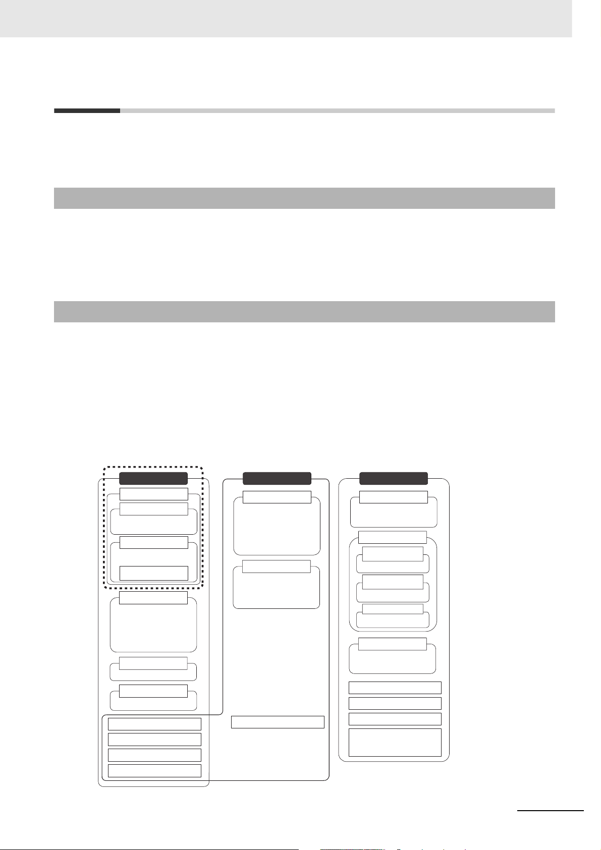
Applicable Products
CJ-series CJ2 CPU Units
• CJ2H-CPU6@-EIP
• CJ2H-CPU6@
•CJ2M-CPU3@
•CJ2M-CPU1@
In this manual, the following notation is used to indicate the CPU Units.
• CJ2H-CPU6@(-EIP): Indicates the CJ2H-CPU6@-EIP and CJ2H-CPU6@ CPU Units.
• CJ2M-CPU@@: Indicates the CJ2M-CPU3@ and CJ2M-CPU1@ CPU Units.
Optional Pulse I/O Modules can be used for pulse I/O with a CJ2M CPU Unit.
CJ2 Series
CJ2 CPU Units
CJ2H CPU Units
CJ2H-CPU6@-EIP
CJ2H-CPU6@
CJ2M CPU Units
CJ2M-CPU3@
CJ2M-CPU1@
Pulse I/O Module for
CJ2M CPU Units
CJ1-H CPU Units
CJ1H-CPU@@H-R
CJ1H-CPU@@H
CJ1G-CPU@@H
CJ1G -CPU@@P
(Loop CPU Units)
CJ1M CPU Units
CJ1M-CPU@@
CJ1 CPU Units
CJ1G-CPU@@
CJ-series Basic I/O Units
CJ-series Special I/O Units
CJ-series CPU Bus Units
CJ-series Power Supply Units
NSJ Series
NSJ Controllers
NSJ5-TQ@@(B)-G5D
NSJ5-SQ@@(B)-G5D
NSJ8-TV@@(B)-G5D
NSJ10-TV@@(B)-G5D
NSJ12-TS@@(B)-G5D
NSJ Controllers
NSJ5-TQ@@(B)-M3D
NSJ5-SQ@@(B)-M3D
NSJ8-TV@@(B)-M3D
NSJ-series Expansion Units
CS Series
CS1-H CPU Units
CS1H-CPU@@H
CS1G-CPU@@H
CS1D CPU Units
CS1D CPU Units
for Duplex Systems
CS1D-CPU@@H
CS1D CPU Units
for Simplex Systems
CS1D-CPU@@S
CS1D Process-control CPU Units
CS1D-CPU@@P
CS1 CPU Units
CS1H-CPU@@(-V)
CS1G-CPU@@(-V)
CS-series Basic I/O Units
CS-series Special I/O Units
CS-series CPU Bus Units
CS-series Power Supply Units
Note: A special Power Supply Unit must
be used for CS1D CPU Units.
CJ2 CPU Unit Software User’s Manual
1
Page 8
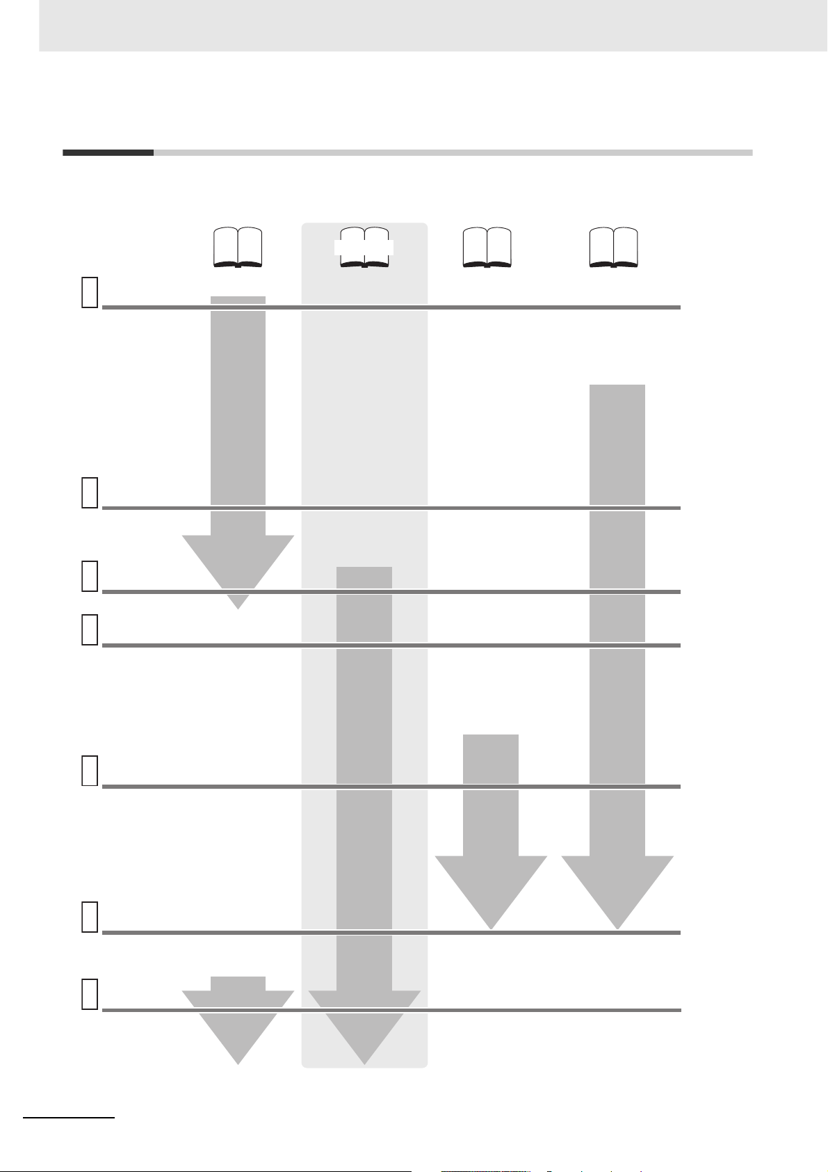
CJ2 CPU Unit Manuals
Information on the CJ2 CPU Units is provided in the following manuals. Refer to the appropriate manual
for the information that is required.
This Manual
Mounting
and Setting
1
Hardware
2
Wiring
CJ-series CJ2 CPU Unit
Hardware User’s Manual
(Cat. No. W472)
• Unit part names and
specifications
• Basic system
configuration
• Unit mounting
procedure
• Setting procedure for
DIP switch and rotary
switches on the front of
the CPU Unit
For details on built-in
EtherNet/IP port, refer to
the EtherNet/IP Unit
Operation Manual (W465)
CJ-series CJ2 CPU Unit
Software User’s Manual
(Cat. No. W473)
CS/CJ/NSJ Series
Instructions Reference
Manual (Cat. No. W474)
CJ2M CPU Unit Pulse
I/O Module User's
Manual (Cat. No. W486)
• Specifications and wiring
of Pulse I/O Modules
• Available pulse I/O
functions and allocations
Connecting
Online to
3
the PLC
Software
4
Setup
Creating the
5
Program
Checking
and
Debugging
6
Operation
• Wiring the Power
Supply Unit
• Wring Basic I/O Units
and external I/O
devices
CX-Programmer Support
Software Connecting
Cables
Procedures for connecting
the CX-Programmer
Support Software
Software setting methods for the
CPU Unit (including I/O memory
allocation, PLC Setup settings,
Special I/O Unit parameters,
CPU Bus Unit parameters, and
routing tables.)
For details on built-in EtherNet/IP
port, refer to the EtherNet/IP Unit
Operation Manual (W465).
• Program types and basic
information
• CPU Unit operation
• Internal memory
• Data management using
file memory in the CPU
Unit
• Built-in CPU functions
• Settings
Detailed information
on programming
instructions
• Pulse I/O Module
specifications
• Wiring methods between
Pulse I/O Modules and
external I/O devices
Software setting
procedures for Pulse I/O
Modules (I/O memory
allocations and PLC
Setup settings)
Pulse I/O functions
Maintenance
and
7
Troubleshooting
2
• Checking I/O wiring, setting the
Auxiliary Area settings, and
performing trial operation
• Monitoring and debugging with
the CX-Programmer
Error codes and
remedies if a problem
occurs
CJ2 CPU Unit Software User’s Manual
Page 9

Manual Configuration
The CJ2 CPU manuals are organized in the sections listed in the following tables. Refer to the appropriate section in the manuals as required.
Hardware User’s Manual (Cat. No. W472)
Section Content
Section 1 Overview
Section 2 Basic System Configuration and Devices
Section 3 Nomenclature and
Functions
Section 4 Support Software
Section 5 Installation
Section 6 Troubleshooting
Section 7 Inspection and Maintenance
Section 8 Backup Operations This section describes the procedure to back up PLC data.
Appendices
This section gives an overview of the CJ2 CPU Units and describes the features and
specifications.
This section describes the system configuration for the CJ2 CPU Unit.
This section describes the part names and functions of the CPU Unit and Configuration
Units.
This section describes the types of Support Software to use to perform programming and
debugging and how to connect the PLC to the Support Software.
This section describes the installation locations and how to wire CPU Units and Configuration Units.
This section describes how to check the status for errors that occur during system operation and the remedies for those errors.
This section describes periodic inspection, the service life of the Battery and Power Supply Unit, and how to replace the Battery.
The appendices provide Unit dimensions, details on fatal and non-fatal errors, information on connecting to serial ports on the CPU Unit, the procedure for installing the USB
driver on a computer, and information on load short-circuit protection and line disconnection detection.
Software User’s Manual (Cat. No. W473) (This Manual)
Section Content
Section 1 Overview
Section 2 Internal Memory in the
CPU Unit
Section 3 CPU Unit Operation This section describes the internal operation of the CPU Unit.
Section 4 CPU Unit Initialization This section describes the initial setup of the CPU Unit.
Section 5 Understanding Programming
Section 6 I/O Memory Areas This section describes the I/O memory areas in the CPU Unit.
Section 7 File Operations
Section 8 I/O Allocations and
Unit Settings
Section 9 PLC Setup
Section 10 CPU Unit Functions This section describes functions that are built into the CPU Unit.
Section 11 Programming Devices
and Communications
Section 12 CPU Unit Cycle Time This section describes how to monitor and calculate the cycle time.
Appendices
This section gives an overview of the CJ2 CPU Units and describes the features and
specifications.
This section describes the types of memory in the CPU Unit and the data that is stored.
This section describes program types and programming details, such as symbols and
programming instructions.
This section describes the files that can be stored in the CPU Unit, the storage destination for those files, and file operations.
This section describes the I/O allocations used to exchange data between the CPU Unit
and other Units.
This section describes details on the PLC Setup settings, which are used to perform
basic settings for the CPU Unit.
This section describes the procedure for connecting the CJ2 CPU Unit to the CX-Programmer or other Support Software and to other devices.
The appendices provide information on programming instructions, execution times, number of steps, Auxiliary Area words and bits, a memory map of the continuous PLC memory addresses, I/O memory operation when power is interrupted, and a comparison of
CJ-series and CS-series PLCs.
CJ2 CPU Unit Software User’s Manual
3
Page 10

Instructions Reference Manual (Cat. No. W474)
Section Content
Section 1 Basic Understanding
of Instructions
Section 2 Summary of Instructions
Section 3 Instructions
Section 4 Instruction Execution
Times and Number of Steps
Appendices
This section provides basic information on designing ladder programs for a CS/CJ/NSJseries CPU Unit.
This section provides a summary of instructions used with a CS/CJ/NSJ-series CPU
Unit.
This section describes the functions, operands and sample programs of the instructions
that are supported by a CS/CJ/NSJ-series CPU Unit.
This section provides the instruction execution times for each CS/CJ/NSJ-series CPU
Unit instruction.
The appendices provide a list of instructions by function code and by mnemonic and an
ASCII table for the CS/CJ/NSJ-series CPU Units.
Pulse I/O Module User's Manual (Cat. No. W486)
Section Content
Section 1 Overview
Section 2 I/O Application Procedures and Function Allocations
Section 3 I/O Specifications and
Wiring for Pulse I/O Modules
Section 4 General-purpose I/O This section describes the general-purpose I/O.
Section 5 Quick-response Inputs
Section 6 Interrupts This section describes the interrupt input function.
Section 7 High-speed Counters This section describes the high-speed counter inputs and high-speed counter interrupts.
Section 8 Pulse Outputs
Section 9 PWM Outputs This section describes the variable-duty-factor (PWM) outputs.
Appendices
This section gives an overview of the Pulse I/O Modules and the pulse I/O functions of
the CJ2M.
This section lists the pulse functions of the CJ2M CPU Units and describes the overall
application flow and the allocation of the functions.
This section provides the specifications and describes the wiring of the Pulse I/O Module.
This section describes the quick-response function that can be used to input signals that
are shorter than the cycle time.
This section describes positioning functions, such as trapezoidal control, S-curve control,
jogging, and origin search functions.
The appendices provide a table of flag changes for pulse outputs, a comparison table
with other models, and a performance table.
4
CJ2 CPU Unit Software User’s Manual
Page 11
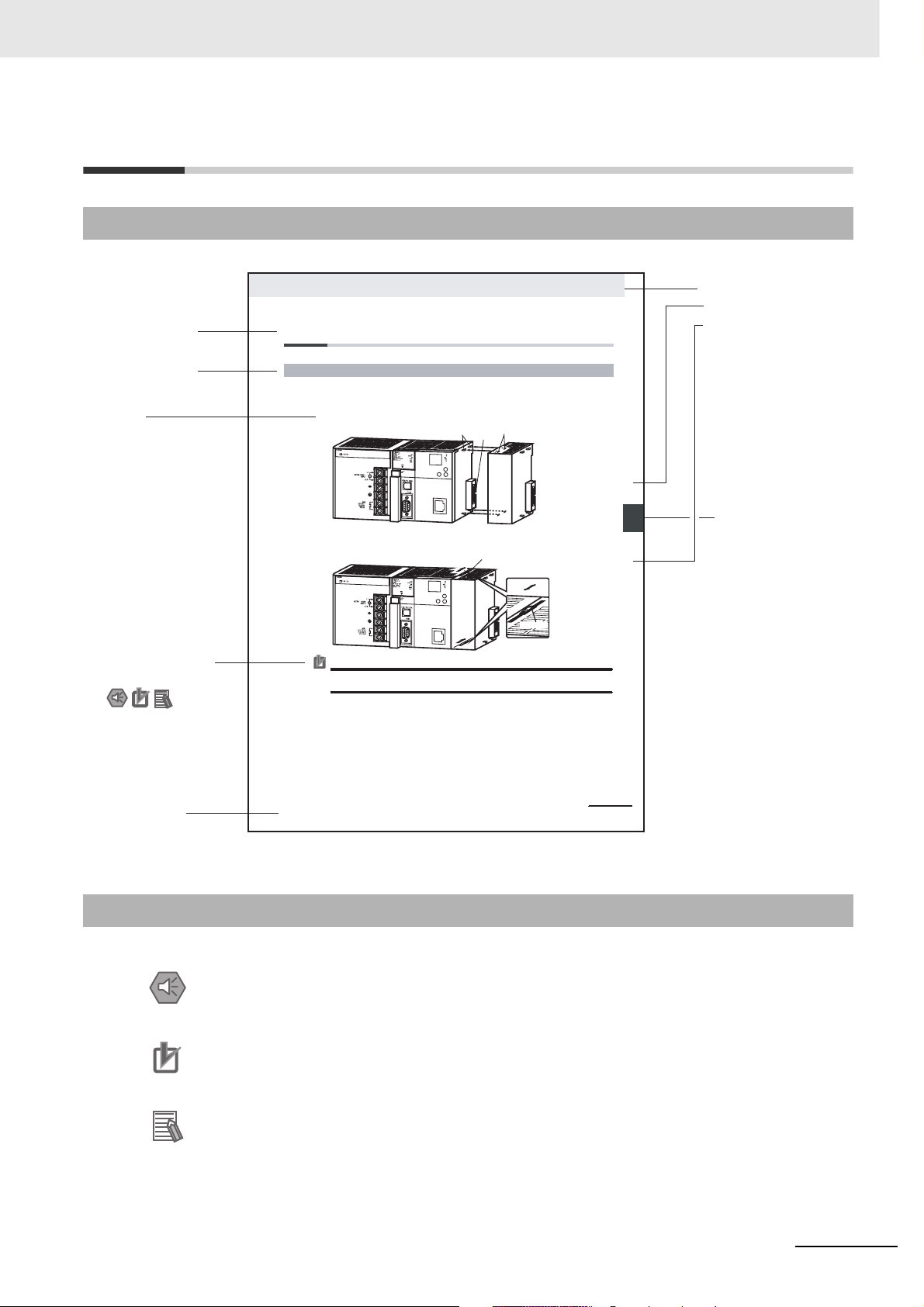
Manual Structure
Page Structure
The following page structure is used in this manual.
Level 2 heading
Level 3 heading
A step
in a procedure
Special Information
(See below.)
5-2 Installation
5-2-1 Connecting PLC Components
The Units that make up a CJ-series PLC can be connected simply by pressing the Units together and
locking the sliders by moving them toward the back of the Units. The End Cover is connected in the
same way to the Unit on the far right side of the PLC.
1. Join the Units so that the connectors fit exactly.
2. The yellow sliders at the top and bottom of each Unit lock the Units together. Move the sliders
toward the back of the Units as shown below until they click into place.
Precautions for Correct UsePrecautions for Correct Use
If the locking tabs are not secured properly, the connectors may become loose and not function
properly. Be sure to slide the locking tabs until they are securely in place.
Hook
Connector
Move the sliders toward the back
until they lock into place.
Hook holes
Release
Lock
Slider
5 Installation
Level 1 heading
Level 2 heading
Level 3 heading
Gives the current
headings.
noitallatsnI 2-5
5
Page tab
Gives the number
of the section.
gnitcennoC 1-2-5
P
opmoC CL
stnen
Manual name
CJ2 CPU Unit Hardware User’s Manual
This illustration is provided only as a sample and may not literally appear in this manual.
Special Information
Special information in this manual is classified as follows:
Precautions for Safe Use
Precautions on what to do and what not to do to ensure using the product safely.
Precautions for Correct Use
Precautions on what to do and what not to do to ensure proper operation and performance.
Additional Information
Additional information to increase understanding or make operation easier.
5-13
CJ2 CPU Unit Software User’s Manual
5
Page 12

6
CJ2 CPU Unit Software User’s Manual
Page 13

Sections in this Manual
1
2
3
4
5
Overview
Internal Memory
in the CPU Unit
CPU Unit
Operation
CPU Unit
Initialization
Understanding Programming
10
11
12
A
CPU Unit
Functions
Programming Devices
and Communications
CPU Unit
Cycle Time
Appendices
1
2
3
4
10
11
12
A
5
6
7
6
7
8
9
8
I/O Memory Areas
9
File Operations
I/O Allocations and Unit Settings
PLC Setup
CJ2 CPU Unit Software User’s Manual
7
Page 14

8
CJ2 CPU Unit Software User’s Manual
Page 15

CONTENTS
Introduction............................................................................................................... 1
CJ2 CPU Unit Manuals ............................................................................................. 2
Manual Structure ...................................................................................................... 5
Sections in this Manual............................................................................................ 7
Safety Precautions ................................................................................................. 21
Application Precautions......................................................................................... 25
Operating Environment Precautions .................................................................... 30
Regulations and Standards ................................................................................... 31
Unit Versions of CJ2 CPU Units ............................................................................ 33
Related Manuals ..................................................................................................... 39
Section 1 Overview
1-1 Overview of CJ2 CPU Units ....................................................................................................1-2
1-1-1 Overview..................................................................................................................................... 1-2
1-1-2 CJ2 CPU Unit Features .............................................................................................................. 1-4
1-2 Basic Operating Procedure .................................................................................................. 1-12
Section 2 Internal Memory in the CPU Unit
2-1 Overview................................................................................................................................... 2-2
2-1-1 Memory Configuration ................................................................................................................ 2-2
2-1-2 Memory Areas and Stored Data ................................................................................................. 2-3
2-1-3 Transferring Data from a Programming Device to the CPU Unit................................................. 2-4
Section 3 CPU Unit Operation
3-1 CPU Unit Internal Operation ................................................................................................... 3-2
3-1-1 Overview..................................................................................................................................... 3-2
3-1-2 Cycle Time.................................................................................................................................. 3-4
3-1-3 Processing at Power Interruptions.............................................................................................. 3-7
3-2 CPU Unit Operating Modes.....................................................................................................3-8
3-2-1 Operating Modes ........................................................................................................................ 3-8
3-2-2 Checking the Operating Mode.................................................................................................... 3-9
3-2-3 Changing the Operating Mode.................................................................................................. 3-10
3-2-4 Operating Mode Details............................................................................................................ 3-14
CJ2 CPU Unit Software User’s Manual
9
Page 16

Section 4 CPU Unit Initialization
4-1 Overview of CPU Unit Initialization ........................................................................................ 4-2
4-1-1 CPU Unit Initial Settings..............................................................................................................4-2
4-2 PLC Setup ................................................................................................................................ 4-8
4-3 Creating I/O Tables .................................................................................................................. 4-9
4-3-1 I/O Tables ....................................................................................................................................4-9
4-3-2 Automatic Allocation..................................................................................................................4-10
4-3-3 Manual Allocation......................................................................................................................4-10
4-4 Setting Routing Tables.......................................................................................................... 4-11
4-4-1 Routing Tables ..........................................................................................................................4-11
4-4-2 Cases in Which Routing Tables Are Required ..........................................................................4-13
4-4-3 Setting and Transferring Routing Tables ...................................................................................4-14
4-5 Setting Allocated DM Area Words for Special I/O Units and CPU Bus Units ................... 4-15
4-5-1 Setting Allocated DM Area Words for Special I/O Units and CPU Bus Units............................ 4-15
4-5-2 Setting Procedure ..................................................................................................................... 4-15
4-6 CPU Bus Unit Setup Area ..................................................................................................... 4-16
4-6-1 CPU Bus Unit Setup Area.........................................................................................................4-16
4-6-2 Setting Procedure ..................................................................................................................... 4-16
Section 5 Understanding Programming
5-1 Programming ........................................................................................................................... 5-3
5-1-1 Programming Overview...............................................................................................................5-3
5-1-2 Basic Ladder Diagram Concepts ................................................................................................ 5-6
5-1-3 ST Language............................................................................................................................... 5-8
5-1-4 SFC Overview.............................................................................................................................5-9
5-2 Tasks....................................................................................................................................... 5-11
5-2-1 Overview of Tasks .....................................................................................................................5-11
5-2-2 Cyclic Tasks ..............................................................................................................................5-14
5-2-3 Interrupt Tasks ..........................................................................................................................5-20
5-2-4 Designing Tasks........................................................................................................................5-30
5-3 Sections.................................................................................................................................. 5-40
5-3-1 Overview of Sections ................................................................................................................5-40
5-4 Function Blocks..................................................................................................................... 5-42
5-4-1 Function Blocks.........................................................................................................................5-42
5-4-2 Features of Function Blocks......................................................................................................5-43
5-4-3 Function Block Specifications ...................................................................................................5-44
5-5 Symbols.................................................................................................................................. 5-47
5-5-1 Overview ...................................................................................................................................5-47
5-5-2 Types of Symbols......................................................................................................................5-48
5-5-3 Global Symbols.........................................................................................................................5-50
5-5-4 Local Symbols...........................................................................................................................5-50
5-5-5 Network Symbols (CJ2H-CPU6
5-5-6 Variables in Function Blocks .....................................................................................................5-55
5-5-7 Symbol Data Types ...................................................................................................................5-56
5-5-8 Automatic Address Allocation to Symbols................................................................................. 5-61
@-EIP and CJ2M-CPU3@ Only) .............................................5-51
5-6 Instructions ............................................................................................................................ 5-62
5-6-1 Basic Understanding of Instructions .........................................................................................5-62
5-6-2 Specifying Operands.................................................................................................................5-69
5-6-3 Data Formats ............................................................................................................................ 5-77
5-6-4 I/O Refresh Timing.................................................................................................................... 5-81
10
CJ2 CPU Unit Software User’s Manual
Page 17

5-7 Index Registers ...................................................................................................................... 5-86
5-7-1 What Are Index Registers?....................................................................................................... 5-86
5-7-2 Using Index Registers............................................................................................................... 5-86
5-7-3 Processing Related to Index Registers..................................................................................... 5-91
5-7-4 Monitoring Index Registers....................................................................................................... 5-92
5-7-5 Sharing Index and Data Registers between Tasks................................................................... 5-93
5-8 Specifying Address Offsets.................................................................................................. 5-95
5-8-1 Overview................................................................................................................................... 5-95
5-8-2 Examples of Address Offset Application................................................................................... 5-97
5-9 Checking Programs............................................................................................................... 5-98
5-9-1 Errors during CX-Programmer Input......................................................................................... 5-98
5-9-2 Program Checks with the CX-Programmer............................................................................... 5-98
5-9-3 Debugging with the Simulator................................................................................................... 5-99
5-9-4 Program Execution Check ...................................................................................................... 5-102
5-10 Precautions .......................................................................................................................... 5-105
5-10-1 Condition Flags....................................................................................................................... 5-105
5-10-2 Special Program Sections ...................................................................................................... 5-110
Section 6 I/O Memory Areas
6-1 I/O Memory Areas .................................................................................................................... 6-2
6-1-1 I/O Memory Area Overview ........................................................................................................ 6-2
6-1-2 I/O Memory Area Structure......................................................................................................... 6-4
6-1-3 Holding I/O Memory Values........................................................................................................ 6-6
6-2 I/O Area..................................................................................................................................... 6-8
6-2-1 Input Bits..................................................................................................................................... 6-8
6-2-2 Output Bits................................................................................................................................ 6-10
6-3 Data Link Area ....................................................................................................................... 6-13
6-4 Synchronous Data Refresh Area.......................................................................................... 6-14
6-5 CPU Bus Unit Area ................................................................................................................ 6-15
6-6 Special I/O Unit Area ............................................................................................................. 6-16
6-7 Pulse I/O Area ........................................................................................................................ 6-17
6-8 Serial PLC Link Area ............................................................................................................. 6-18
6-9 DeviceNet Area ...................................................................................................................... 6-19
6-10 Work Area............................................................................................................................... 6-20
6-11 Holding Area .......................................................................................................................... 6-21
6-12 Auxiliary Area ........................................................................................................................ 6-23
6-13 Temporary Relay Area........................................................................................................... 6-24
6-14 Data Memory Area ................................................................................................................. 6-25
6-15 Extended Data Memory Area ................................................................................................ 6-28
6-16 Timer Areas............................................................................................................................ 6-32
6-17 Counter Areas........................................................................................................................ 6-34
6-18 Task Flags .............................................................................................................................. 6-35
6-19 Index Registers ...................................................................................................................... 6-36
6-20 Data Registers ....................................................................................................................... 6-41
6-21 Condition Flags ..................................................................................................................... 6-43
6-22 Clock Pulses .......................................................................................................................... 6-45
CJ2 CPU Unit Software User’s Manual
11
Page 18

Section 7 File Operations
7-1 File Memory.............................................................................................................................. 7-2
7-1-1 Types of File Memory..................................................................................................................7-2
7-1-2 Initializing File Memory ...............................................................................................................7-3
7-1-3 Memory Card Precautions ..........................................................................................................7-5
7-2 Types of Files Stored in File Memory .................................................................................... 7-7
7-2-1 File Types....................................................................................................................................7-7
7-2-2 Creating and Saving Files for File Memory ...............................................................................7-10
7-3 File Memory Operations........................................................................................................ 7-11
7-3-1 Types of File Memory Operations .............................................................................................7-11
7-3-2 File Memory Operating Procedures and File Memory Files...................................................... 7-13
7-3-3 Restrictions on File Use ............................................................................................................7-19
7-3-4 File Sizes...................................................................................................................................7-20
7-3-5 Relation between Support Software and File Memory Files .....................................................7-21
Section 8 I/O Allocations and Unit Settings
8-1 I/O Allocations ......................................................................................................................... 8-2
8-1-1 I/O Allocations.............................................................................................................................8-2
8-1-2 Automatic Allocation....................................................................................................................8-5
8-1-3 Manual Allocation........................................................................................................................ 8-9
8-1-4 I/O Table Errors and Precautions ..............................................................................................8-17
8-2 Setting CPU Bus Units and Special I/O Units ..................................................................... 8-20
8-2-1 Setting Parameters ...................................................................................................................8-20
8-2-2 Data Exchange..........................................................................................................................8-24
Section 9 PLC Setup
9-1 Overview of the PLC Setup..................................................................................................... 9-2
9-2 PLC Setup Settings ................................................................................................................. 9-4
9-3 PLC Setup Settings ................................................................................................................. 9-5
9-3-1 Startup Operation Settings..........................................................................................................9-5
9-3-2 CPU Unit Settings .......................................................................................................................9-8
9-3-3 Timings/Synchronous Settings.................................................................................................. 9-14
9-3-4 Special I/O Unit Cyclic Refreshing ............................................................................................9-19
9-3-5 Basic I/O Unit Rack Response Times.......................................................................................9-21
9-3-6 Serial Port Settings ...................................................................................................................9-23
9-3-7 Peripheral Service.....................................................................................................................9-30
9-3-8 FINS Protection.........................................................................................................................9-31
9-3-9 I/O Module................................................................................................................................. 9-32
Section 10 CPU Unit Functions
10-1 Clock Functions..................................................................................................................... 10-3
10-1-1 Clock Functions.........................................................................................................................10-3
10-1-2 Times Stored in Memory...........................................................................................................10-4
10-1-3 Free-running Timers..................................................................................................................10-6
10-2 Cycle Time/High-speed Processing..................................................................................... 10-7
10-2-1 Minimum Cycle Time.................................................................................................................10-7
10-2-2 Maximum Cycle Time................................................................................................................10-8
10-2-3 Monitoring the Cycle Time ........................................................................................................10-9
10-2-4 High-speed Inputs..................................................................................................................... 10-9
10-2-5 Background Execution ............................................................................................................10-10
10-2-6 High-speed Interrupt Function ................................................................................................ 10-19
12
CJ2 CPU Unit Software User’s Manual
Page 19

10-3 Startup Settings and Maintenance..................................................................................... 10-22
10-3-1 Holding Settings for Operating Mode Changes and at Startup............................................... 10-22
10-3-2 Power OFF Detection Delay Setting....................................................................................... 10-24
10-3-3 Disabling Power OFF Interrupts.............................................................................................. 10-25
10-3-4 RUN Output ............................................................................................................................ 10-26
10-3-5 Automatic Transfer at Startup ................................................................................................. 10-27
10-4 Unit Management Functions .............................................................................................. 10-35
10-4-1 Basic I/O Unit Management.................................................................................................... 10-35
10-4-2 CPU Bus Unit Flags/Bits......................................................................................................... 10-37
10-4-3 Special I/O Unit Flags/Bits...................................................................................................... 10-38
10-5 Memory Management Functions........................................................................................ 10-39
10-5-1 Automatic Backup................................................................................................................... 10-39
10-5-2 EM File Memory Functions ..................................................................................................... 10-41
10-5-3 Comment Memory .................................................................................................................. 10-42
10-5-4 Replacing the Entire Program during Operation ..................................................................... 10-43
10-6 Security Functions .............................................................................................................. 10-50
10-6-1 Write-protection Using the DIP Switch ................................................................................... 10-50
10-6-2 Read Protection Using Passwords ......................................................................................... 10-50
10-6-3 Program Operation Protection Using Production Lot Numbers.............................................. 10-55
10-6-4 Write Protection from FINS Commands ................................................................................. 10-56
10-6-5 PLC Names ............................................................................................................................ 10-60
10-7 Debugging............................................................................................................................ 10-63
10-7-1 Forced Set/Reset.................................................................................................................... 10-63
10-7-2 Test Input ................................................................................................................................ 10-64
10-7-3 Differential Monitoring............................................................................................................. 10-64
10-7-4 Online Editing ......................................................................................................................... 10-65
10-7-5 Turning OFF Outputs .............................................................................................................. 10-67
10-7-6 Tracing Data............................................................................................................................ 10-68
10-7-7 Storing the Stop Position at Errors ......................................................................................... 10-76
10-7-8 Failure Alarm Instructions....................................................................................................... 10-77
10-7-9 Simulating System Errors ....................................................................................................... 10-78
10-7-10 Failure Point Detection............................................................................................................ 10-79
10-8 Synchronous Unit Operation.............................................................................................. 10-81
10-8-1 Overview................................................................................................................................. 10-81
10-8-2 Details on Synchronous Unit Operation.................................................................................. 10-84
10-8-3 Synchronous Unit Operation Specifications ........................................................................... 10-87
10-8-4 Synchronous Data Refresh..................................................................................................... 10-88
10-8-5 Restrictions in Using Synchronous Unit Operation................................................................. 10-92
10-8-6 Application Procedure............................................................................................................. 10-94
10-8-7 PLC Setup .............................................................................................................................. 10-95
10-8-8 Writing the Synchronous Interrupt Task.................................................................................. 10-97
10-8-9 Adjusting and Troubleshooting Synchronous Unit Operation ................................................. 10-98
Section 11 Programming Devices and Communications
11-1 Accessing a PLC from the CX-Programmer........................................................................ 11-2
11-1-1 Overview................................................................................................................................... 11-2
11-1-2 System Configurations for Accessible PLCs............................................................................. 11-4
11-1-3 Accessing a PLC from the CX-Programmer ............................................................................. 11-8
11-1-4 Automatic Online Connection ................................................................................................. 11-11
11-2 Serial Communications....................................................................................................... 11-15
11-2-1 Overview of Serial Communications....................................................................................... 11-15
11-3 Communications Networks ................................................................................................ 11-29
CJ2 CPU Unit Software User’s Manual
13
Page 20

Section 12 CPU Unit Cycle Time
12-1 Monitoring the Cycle Time.................................................................................................... 12-2
12-1-1 Monitoring the Cycle Time ........................................................................................................12-2
12-2 Computing the Cycle Time ................................................................................................... 12-4
12-2-1 CPU Unit Operation Flowchart.................................................................................................. 12-4
12-2-2 Cycle Time Overview ................................................................................................................12-5
12-2-3 I/O Unit Refresh Times for Individual Units...............................................................................12-7
12-2-4 Cycle Time Calculation Example ............................................................................................12-11
12-2-5 Online Editing Cycle Time Extension......................................................................................12-13
12-2-6 I/O Response Time .................................................................................................................12-13
12-2-7 Response Time for Input Interrupts.........................................................................................12-14
12-2-8 Response Performance of Serial PLC Links........................................................................... 12-15
Appendices
A-1 Instruction Functions ..............................................................................................................A-3
A-1-1 Sequence Input Instructions .......................................................................................................A-3
A-1-2 Sequence Output Instructions.....................................................................................................A-5
A-1-3 Sequence Control Instructions ....................................................................................................A-6
A-1-4 Timer and Counter Instructions.................................................................................................A-10
A-1-5 Comparison Instructions ...........................................................................................................A-14
A-1-6 Data Movement Instructions .....................................................................................................A-18
A-1-7 Data Shift Instructions...............................................................................................................A-20
A-1-8 Increment/Decrement Instructions ............................................................................................A-24
A-1-9 Symbol Math Instructions..........................................................................................................A-24
A-1-10 Conversion Instructions.............................................................................................................A-29
A-1-11 Logic Instructions ......................................................................................................................A-35
A-1-12 Special Math Instructions..........................................................................................................A-37
A-1-13 Floating-point Math Instructions................................................................................................A-38
A-1-14 Double-precision Floating-point Instructions .............................................................................A-42
A-1-15 Table Data Processing Instructions...........................................................................................A-45
A-1-16 Tracking Instructions .................................................................................................................A-49
A-1-17 Data Control Instructions ..........................................................................................................A-50
A-1-18 Subroutine Instructions .............................................................................................................A-54
A-1-19 Interrupt Control Instructions.....................................................................................................A-55
A-1-20 High-speed Counter/Pulse Output Instructions.........................................................................A-56
A-1-21 Step Instructions .......................................................................................................................A-58
A-1-22 Basic I/O Unit Instructions.........................................................................................................A-58
A-1-23 Serial Communications Instructions..........................................................................................A-61
A-1-24 Network Instructions .................................................................................................................A-63
A-1-25 File Memory Instructions...........................................................................................................A-65
A-1-26 Display Instructions...................................................................................................................A-66
A-1-27 Clock Instructions......................................................................................................................A-67
A-1-28 Debugging Instructions .............................................................................................................A-68
A-1-29 Failure Diagnosis Instructions ...................................................................................................A-68
A-1-30 Other Instructions......................................................................................................................A-69
A-1-31 Block Programming Instructions ...............................................................................................A-70
A-1-32 Text String Processing Instructions ...........................................................................................A-74
A-1-33 Task Control Instructions...........................................................................................................A-77
A-1-34 Model Conversion Instructions..................................................................................................A-77
A-1-35 Special Function Block Instructions ..........................................................................................A-78
14
CJ2 CPU Unit Software User’s Manual
Page 21

A-2 Instruction Execution Times and Number of Steps ...........................................................A-80
A-2-1 Sequence Input Instructions .....................................................................................................A-81
A-2-2 Sequence Output Instructions ..................................................................................................A-81
A-2-3 Sequence Control Instructions ................................................................................................. A-82
A-2-4 Timer and Counter Instructions ................................................................................................A-83
A-2-5 Comparison Instructions ...........................................................................................................A-84
A-2-6 Data Movement Instructions.....................................................................................................A-85
A-2-7 Data Shift Instructions .............................................................................................................. A-86
A-2-8 Increment/Decrement Instructions............................................................................................A-87
A-2-9 Symbol Math Instructions .........................................................................................................A-87
A-2-10 Conversion Instructions ............................................................................................................ A-89
A-2-11 Logic Instructions......................................................................................................................A-91
A-2-12 Special Math Instructions ......................................................................................................... A-91
A-2-13 Floating-point Math Instructions ...............................................................................................A-92
A-2-14 Double-precision Floating-point Instructions............................................................................. A-93
A-2-15 Table Data Processing Instructions ..........................................................................................A-94
A-2-16 Tracking Instructions .................................................................................................................A-96
A-2-17 Data Control Instructions ..........................................................................................................A-96
A-2-18 Subroutine Instructions.............................................................................................................A-97
A-2-19 Interrupt Control Instructions ....................................................................................................A-98
A-2-20 High-speed Counter/Pulse Output Instructions ........................................................................A-98
A-2-21 Step Instructions..................................................................................................................... A-101
A-2-22 Basic I/O Unit Instructions ......................................................................................................A-101
A-2-23 Serial Communications Instructions ....................................................................................... A-102
A-2-24 Network Instructions ...............................................................................................................A-103
A-2-25 File Memory Instructions ........................................................................................................ A-103
A-2-26 Display Instructions.................................................................................................................A-104
A-2-27 Clock Instructions ................................................................................................................... A-104
A-2-28 Debugging Instructions...........................................................................................................A-104
A-2-29 Failure Diagnosis Instructions.................................................................................................A-104
A-2-30 Other Instructions ...................................................................................................................A-105
A-2-31 Block Programming Instructions.............................................................................................A-105
A-2-32 Text String Processing Instructions......................................................................................... A-107
A-2-33 Task Control Instructions ........................................................................................................A-108
A-2-34 Model Conversion Instructions ...............................................................................................A-108
A-2-35 Special Function Block Instructions........................................................................................ A-109
A-2-36 SFC Instructions .....................................................................................................................A-109
A-2-37 Function Block Instance Execution Time................................................................................ A-109
A-3 Auxiliary Area ......................................................................................................................A-111
A-3-1 Read-only Area (Set by System) ............................................................................................A-111
A-3-2 Read/Write Area (Set by User)............................................................................................... A-150
A-3-3 Details on Auxiliary Area Operation........................................................................................A-161
A-4 Memory Map of PLC Memory Addresses..........................................................................A-164
A-4-1 PLC Memory Addresses......................................................................................................... A-164
A-4-2 Memory Map...........................................................................................................................A-165
A-5 Operation for Power Interruptions .....................................................................................A-166
A-5-1 Power OFF Operation.............................................................................................................A-166
A-5-2 Instruction Execution for Power Interruptions .........................................................................A-168
A-6 EtherNet/IP Connections from Windows XP (SP2 or Higher), Windows Vista,
or Windows 7 .....................................................................................................................A-170
A-6-1 Changing Windows Firewall Settings......................................................................................A-170
A-7 PLC Comparison Charts: CJ-series and CS-series PLCs ...............................................A-173
A-8 Functions Supported for Unit Versions.............................................................................A-177
A-8-1 CJ2H CPU Unit.......................................................................................................................A-177
A-8-2 CJ2M CPU Unit ......................................................................................................................A-178
Index ................................................................................................................Index-1
Revision History ....................................................................................... Revision-1
CJ2 CPU Unit Software User’s Manual
15
Page 22

16
CJ2 CPU Unit Software User’s Manual
Page 23

Read and Understand this Manual
Please read and understand this manual before using the product. Please consult your OMRON representative
if you have any questions or comments.
Warranty and Limitations of Liability
WARRANTY
OMRON's exclusive warranty is that the products are free from defects in materials and workmanship for a
period of one year (or other period if specified) from date of sale by OMRON.
OMRON MAKES NO WARRANTY OR REPRESENTATION, EXPRESS OR IMPLIED, REGARDING NONINFRINGEMENT, MERCHANTABILITY, OR FITNESS FOR PARTICULAR PURPOSE OF THE
PRODUCTS. ANY BUYER OR USER ACKNOWLEDGES THAT THE BUYER OR USER ALONE HAS
DETERMINED THAT THE PRODUCTS WILL SUITABLY MEET THE REQUIREMENTS OF THEIR
INTENDED USE. OMRON DISCLAIMS ALL OTHER WARRANTIES, EXPRESS OR IMPLIED.
LIMITATIONS OF LIABILITY
OMRON SHALL NOT BE RESPONSIBLE FOR SPECIAL, INDIRECT, OR CONSEQUENTIAL DAMAGES,
LOSS OF PROFITS OR COMMERCIAL LOSS IN ANY WAY CONNECTED WITH THE PRODUCTS,
WHETHER SUCH CLAIM IS BASED ON CONTRACT, WARRANTY, NEGLIGENCE, OR STRICT
LIABILITY.
In no event shall the responsibility of OMRON for any act exceed the individual price of the product on which
liability is asserted.
IN NO EVENT SHALL OMRON BE RESPONSIBLE FOR WARRANTY, REPAIR, OR OTHER CLAIMS
REGARDING THE PRODUCTS UNLESS OMRON'S ANALYSIS CONFIRMS THAT THE PRODUCTS
WERE PROPERLY HANDLED, STORED, INSTALLED, AND MAINTAINED AND NOT SUBJECT TO
CONTAMINATION, ABUSE, MISUSE, OR INAPPROPRIATE MODIFICATION OR REPAIR.
CJ2 CPU Unit Software User’s Manual
17
Page 24

Application Considerations
SUITABILITY FOR USE
OMRON shall not be responsible for conformity with any standards, codes, or regulations that apply to the
combination of products in the customer's application or use of the products.
At the customer's request, OMRON will provide applicable third party certification documents identifying
ratings and limitations of use that apply to the products. This information by itself is not sufficient for a
complete determination of the suitability of the products in combination with the end product, machine,
system, or other application or use.
The following are some examples of applications for which particular attention must be given. This is not
intended to be an exhaustive list of all possible uses of the products, nor is it intended to imply that the uses
listed may be suitable for the products:
• Outdoor use, uses involving potential chemical contamination or electrical interference, or conditions or
uses not described in this manual.
• Nuclear energy control systems, combustion systems, railroad systems, aviation systems, medical
equipment, amusement machines, vehicles, safety equipment, and installations subject to separate
industry or government regulations.
• Systems, machines, and equipment that could present a risk to life or property.
Please know and observe all prohibitions of use applicable to the products.
NEVER USE THE PRODUCTS FOR AN APPLICATION INVOLVING SERIOUS RISK TO LIFE OR
PROPERTY WITHOUT ENSURING THAT THE SYSTEM AS A WHOLE HAS BEEN DESIGNED TO
ADDRESS THE RISKS, AND THAT THE OMRON PRODUCTS ARE PROPERLY RATED AND
INSTALLED FOR THE INTENDED USE WITHIN THE OVERALL EQUIPMENT OR SYSTEM.
PROGRAMMABLE PRODUCTS
OMRON shall not be responsible for the user's programming of a programmable product, or any
consequence thereof.
18
CJ2 CPU Unit Software User’s Manual
Page 25

Disclaimers
CHANGE IN SPECIFICATIONS
Product specifications and accessories may be changed at any time based on improvements and other
reasons.
It is our practice to change model numbers when published ratings or features are changed, or when
significant construction changes are made. However, some specifications of the products may be changed
without any notice. When in doubt, special model numbers may be assigned to fix or establish key
specifications for your application on your request. Please consult with your OMRON representative at any
time to confirm actual specifications of purchased products.
DIMENSIONS AND WEIGHTS
Dimensions and weights are nominal and are not to be used for manufacturing purposes, even when
tolerances are shown.
PERFORMANCE DATA
Performance data given in this manual is provided as a guide for the user in determining suitability and does
not constitute a warranty. It may represent the result of OMRON's test conditions, and the users must
correlate it to actual application requirements. Actual performance is subject to the OMRON Warranty and
Limitations of Liability.
ERRORS AND OMISSIONS
The information in this manual has been carefully checked and is believed to be accurate; however, no
responsibility is assumed for clerical, typographical, or proofreading errors, or omissions.
CJ2 CPU Unit Software User’s Manual
19
Page 26

20
CJ2 CPU Unit Software User’s Manual
Page 27
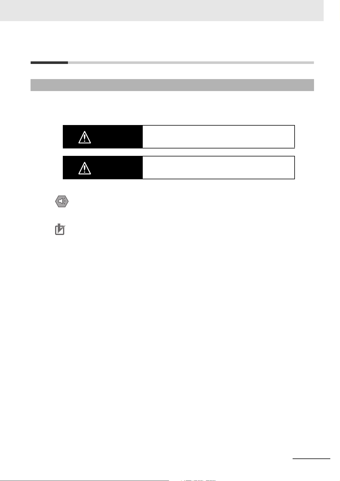
Safety Precautions
Definition of Precautionary Information
The following notation is used in this manual to provide precautions required to ensure safe usage of a
CJ-series PLC. The safety precautions that are provided are extremely important to safety. Always read
and heed the information provided in all safety precautions.
WARNING
Caution
Precautions for Safe Use
Indicates precautions on what to do and what not to do to ensure using the product safely.
Precautions for Correct Use
Indicates precautions on what to do and what not to do to ensure proper operation and performance.
Indicates a potentially hazardous situation which, if not avoided,
could result in death or serious injury. Additionally, there may be
severe property damage.
Indicates a potentially hazardous situation which, if not avoided,
may result in minor or moderate injury, or property damage.
CJ2 CPU Unit Software User’s Manual
21
Page 28
Symbols
The triangle symbol indicates precautions (including warnings).
The specific operation is shown in the triangle and explained in
text. This example indicates a precaution for electric shock.
The circle and slash symbol indicates operations that you must
not do. The specific operation is shown in the circle and
explained in text.
The filled circle symbol indicates operations that you must do.
The specific operation is shown in the circle and explained in
text. This example shows a general precaution for something
that you must do.
The triangle symbol indicates precautions (including warnings).
The specific operation is shown in the triangle and explained in
text. This example indicates a general precaution.
The triangle symbol indicates precautions (including warnings).
The specific operation is shown in the triangle and explained in
text. This example indicates a precaution for hot surfaces.
22
CJ2 CPU Unit Software User’s Manual
Page 29
WARNING
Do not attempt to take any Unit apart or touch the inside of any Unit while the
power is being supplied. Doing so may result in electric shock.
Do not touch any of the terminals or terminal blocks while the power is being
supplied. Doing so may result in electric shock.
Provide safety measures in external circuits (i.e., not in the Programmable
Controller), including the following items, to ensure safety in the system if an
abnormality occurs due to malfunction of the Programmable Controller or
another external factor affecting the operation of the Programmable Controller. “Programmable Controller” indicates the CPU Unit and all other Units and
is abbreviated “PLC” in this manual. Not doing so may result in serious accidents.
• The PLC will turn OFF all outputs when its self-diagnosis function detects
any error or when a severe failure alarm (FALS) instruction is executed.
Unexpected operation, however, may still occur for errors in the I/O control
section, errors in I/O memory, and other errors that cannot be detected by
the self-diagnosis function. As a countermeasure for all such errors, external safety measures must be provided to ensure safety in the system.
• The PLC outputs may remain ON or OFF due to deposition or burning of
the output relays or destruction of the output transistors. As a countermeasure for such problems, external safety measures must be provided to
ensure safety in the system.
• Provide measures in the computer system and programming to ensure
safety in the overall system even if communications errors or malfunctions
occur in data link communications or remote I/O communications.
Confirm safety before transferring data files stored in the file memory (Memory Card or EM file memory) to the I/O area (CIO) of the CPU Unit using a
peripheral tool. Otherwise, the devices connected to the output unit may malfunction regardless of the operation mode of the CPU Unit.
Fail-safe measures must be taken by the customer to ensure safety in the
event of incorrect, missing, or abnormal signals caused by broken signal
lines, momentary power interruptions, or other causes. Serious accidents
may result from abnormal operation if proper measures are not provided.
CJ2 CPU Unit Software User’s Manual
23
Page 30

Caution
Execute online edit only after confirming that no adverse effects will be
caused by extending the cycle time. Otherwise, the input signals may not be
readable.
Confirm safety at the destination node before transferring a program, PLC
Setup, I/O tables, I/O memory contents, or parameters to another node or
changing contents of the any of these items. Transferring or changing data
can result in unexpected system operation.
The CJ2 CPU Units automatically back up the user program and parameter
data to flash memory when these are written to the CPU Unit. I/O memory
including the DM, EM, and Holding Areas), however, is not written to flash
memory.
The DM, EM, and Holding Areas can be held during power interruptions with
a battery. If there is a battery error, the contents of these areas may not be
accurate after a power interruption. If the contents of the DM, EM, and Holding Areas are used to control external outputs, prevent inappropriate outputs
from being made whenever the Battery Error Flag (A402.04) is ON.
Tighten the terminal screws on the AC Power Supply Unit to the torque specified in the operation manual. The loose screws may result in burning or malfunction.
Do not touch the Power Supply Unit when power is being supplied or immediately after the power supply is turned OFF. The Power Supply Unit will be hot
and you may be burned.
When connecting a personal computer or other peripheral device to a PLC to
which a non-insulated Power Supply Unit (CJ1W-PD022) is mounted, either
ground the 0 V side of the external power supply or do not ground the external power supply at all ground. A short-circuit will occur in the external power
supply if incorrect grounding methods are used. Never ground the 24 V side,
as shown below.
Wiring in Which the 24-V Power Supply Will Short
Non-insulated
DC power supply
24 V
Peripheral
0 V
cable
0 V
24
FG
Power Supply
Unit
CPU Unit
Peripheral device (e.g.,
personal computer)
CJ2 CPU Unit Software User’s Manual
Page 31

Application Precautions
Observe the following precautions when using a CJ-series PLC.
z Power Supply
• Always use the power supply voltages specified in the user’s manuals. An incorrect voltage may
result in malfunction or burning.
• Exceeding the capacity of the Power Supply Unit may prevent the CPU Unit or other Units from
starting.
• Take appropriate measures to ensure that the specified power with the rated voltage and frequency is supplied. Be particularly careful in places where the power supply is unstable. An incorrect power supply may result in malfunction.
• Always turn OFF the power supply to the PLC before attempting any of the following. Not turning
OFF the power supply may result in malfunction or electric shock.
• Mounting or dismounting Power Supply Units, I/O Units, CPU Units, Option Boards, Pulse I/O
Modules, or any other Units.
• Assembling the Units.
• Setting DIP switches or rotary switches.
• Connecting cables or wiring the system.
• Connecting or disconnecting the connectors.
• When cross-wiring terminals, the total current for all the terminal will flow in the wire. Make sure
that the current capacity of the wire is sufficient.
• Observe the following precautions when using a Power Supply Unit that supports the Replacement Notification Function.
• Replace the Power Supply Unit within six months if the display on the front of the Power Supply Unit alternates between 0.0 and A02, or if the alarm output automatically turns OFF.
• Keep the alarm output cable separated from power line and high-voltage lines.
• Do not apply a voltage or connect a load exceeding the specifications to the alarm output.
• When storing the Power Supply Unit for more than three months, store it at −20 to 30°C and
25% to 70% humidity to preserve the Replacement Notification Function.
• If the Power Supply Unit is not installed properly, heat buildup may cause the replacement notification signal to appear at the wrong time or may cause interior elements to deteriorate or
become damaged. Use only the standard installation method.
• Do not touch the terminals on the Power Supply Unit immediately after turning OFF the power
supply. Residual voltage may cause electrical shock.
• Observe the following precautions to prevent failure due to difference in electrical potential if the
computer is connected to the PLC.
• Before connecting a laptop computer to the PLC, disconnect the power supply plug of the
computer from the AC outlet. Residual current in the AC adaptor may cause difference in electrical potential to occur between the computer and the PLC. After you connect the computer
and PLC, supply the power again from the AC adaptor.
• If the computer has an FG terminal, make the connections so that it has the same electrical
potential as the FG (GR) terminal on the PLC.
• If the computer is grounded to a separate location, difference in electrical potential may occur
depending on the grounding conditions.
z Installation
• Do not install the PLC near sources of strong high-frequency noise.
• Before touching a Unit, be sure to first touch a grounded metallic object in order to discharge any
static build-up. Not doing so may result in malfunction or damage.
CJ2 CPU Unit Software User’s Manual
25
Page 32

• Be sure that the terminal blocks, connectors, Memory Cards, Option Boards, Pulse I/O Modules,
expansion cables, and other items with locking devices are properly locked into place.
• The sliders on the tops and bottoms of the Power Supply Unit, CPU Unit, I/O Units, Special I/O
Units, CPU Bus Units, and Pulse I/O Modules must be completely locked (until they click into
place) after connecting to adjacent Units. The Unit may not operate properly if the sliders are not
locked in place. It may not be possible to achieve proper functionality if the sliders are not locked.
z Wiring
• Follow the instructions in this manual to correctly perform wiring.
• Double-check all wiring and switch settings before turning ON the power supply. Incorrect wiring
may result in burning.
• Be sure that all terminal screws, and cable connector screws are tightened to the torque specified
in the relevant manuals. Incorrect tightening torque may result in malfunction.
• Mount terminal blocks and connectors only after checking the mounting location carefully.
• Leave the label attached to the Unit when wiring. Removing the label may result in malfunction if
foreign matter enters the Unit.
• Remove the label after the completion of wiring to ensure proper heat dissipation. Leaving the
label attached may result in malfunction.
• Use crimp terminals for wiring. Do not connect bare stranded wires directly to terminals. Connection of bare stranded wires may result in burning.
• Do not apply voltages to the Input Units in excess of the rated input voltage. Excess voltages may
result in burning.
• Always connect to a ground of 100 Ω or less when installing the Units. Not connecting to a ground
of 100 Ω or less may result in electric shock.
A ground of 100 Ω or less must be installed when shorting the GR and LG terminals on the Power
Supply Unit.
• Do not apply voltages or connect loads to the Output Units in excess of the maximum switching
capacity. Excess voltage or loads may result in burning.
• Do not pull on the cables or bend the cables beyond their natural limit. Doing either of these may
break the cables.
• Do not place objects on top of the cables or other wiring lines. Doing so may break the cables.
• Do not use commercially available RS-232C personal computer cables. Always use the special
cables listed in this manual or make cables according to manual specifications. Using commercially available cables may damage the external devices or CPU Unit.
• Never connect pin 6 (5-V power supply) on the RS-232C port on the CPU Unit to any device other
than an NT-AL001 Link Adapter, CJ1W-CIF11 Converter, and Programmable Terminals (NV3WM@20L). The external device or the CPU Unit may be damaged.
26
z Handling
• The Power Supply Unit may possibly be damaged if the entire voltage for a dielectric strength test
is applied or shut OFF suddenly using a switch. Use a variable resistor to gradually increase and
decrease the voltage.
• Separate the line ground terminal (LG) from the functional ground terminal (GR) on the Power
Supply Unit before performing withstand voltage tests or insulation resistance tests. Not doing so
may result in burning.
• Make sure that the DIP switches and DM Area are set correctly before starting operation.
• After replacing the CPU Unit, a Special I/O Unit, or a CPU Bus Unit, make sure that the required
data for the DM Area, Holding Area, and other memory areas has been transferred to the new
Unit before restarting operation.
• Confirm that no adverse effect will occur in the system before attempting any of the following. Not
doing so may result in an unexpected operation.
• Changing the operating mode of the PLC (including the setting of the startup operating mode).
• Force-setting/force-resetting any bit in memory.
CJ2 CPU Unit Software User’s Manual
Page 33

• Changing the present value of any word or any set value in memory.
• Do not attempt to disassemble, repair, or modify any Units. Any attempt to do so may result in malfunction, fire, or electric shock.
• Do not drop the PLC or subject abnormal vibration or shock to it.
• The life of the battery will be reduced if the PLC is left for a period of time without a battery
installed and without power supply, and then a battery is installed without turning ON the power
supply.
• Replace the battery as soon as a battery error occurs or as soon as the specified battery backup
time expires. Be sure to install a replacement battery within two years of the production date
shown on the battery's label.
• Before replacing the battery, turn ON power for at least 5 minutes before starting the replacement
procedure and complete replacing the battery within 5 minutes of turning OFF the power supply.
Memory contents may be corrupted if this precaution is not obeyed.
• If the Battery Error Flag is used in programming the application, confirm system safety even if the
system detects a battery error before you replace the battery while the power is ON.
• Do not short the battery terminals or charge, disassemble, heat, or incinerate the battery. Do not
subject the battery to strong shocks. Doing any of these may result in leakage, rupture, heat generation, or ignition of the battery. Dispose of any battery that has been dropped on the floor or otherwise subjected to excessive shock. Batteries that have been subjected to shock may leak if they
are used.
• UL standards require that only an experienced engineer can replace the battery. Make sure that
an experienced engineer is in charge of battery replacement. Follow the procedure for battery
replacement given in this manual.
• Dispose of the product and batteries according to local ordinances as they apply.
• If the I/O Hold Bit is turned ON, the outputs from the PLC will not be turned OFF and will maintain
their previous status when the PLC is switched from RUN or MONITOR mode to PROGRAM
mode. Make sure that the external loads will not produce dangerous conditions when this occurs.
(When operation stops for a fatal error, including those produced with the FALS(007) instruction,
all outputs from Output Unit will be turned OFF and only the internal output status will be maintained.)
• Unexpected operation may result if inappropriate data link tables or parameters are set. Even if
appropriate data link tables and parameters have been set, confirm that the controlled system will
not be adversely affected before starting or stopping data links.
• Write programs so that any data that is received for data link communications is used only if there
are no errors in the CPU Units that are the sources of the data. Use the CPU Unit error information in the status flags to check for errors in the source CPU Units. If there are errors in source
CPU Units, they may send incorrect data.
• All CPU Bus Units will be restarted when routing tables are transferred from a Programming
Device to the CPU Unit. Restarting these Units is required to read and enable the new routing
tables. Confirm that the system will not be adversely affected before transferring the routing
tables.
• Tag data links will stop between related nodes while tag data link parameters are being transferred during PLC operation. Confirm that the system will not be adversely affected before transferring the tag data link parameters.
• If there is interference with network communications, output status will depend on the devices that
are being used. When using devices with outputs, confirm the operation that will occur when there
is interference with communications, and implement safety measures as required.
CJ2 CPU Unit Software User’s Manual
27
Page 34

• When creating an AUTOEXEC.IOM file from a Programming Device (a Programming Console or
the CX-Programmer) to automatically transfer data at startup, set the first write address to
D20000 and be sure that the size of data written does not exceed the size of the DM Area. When
the data file is read from the Memory Card at startup, data will be written in the CPU Unit starting
at D20000 even if another address was set when the AUTOEXEC.IOM file was created. Also, if
the DM Area is exceeded (which is possible when the CX-Programmer is used), the remaining
data will be written to the EM Area.
• The user program and parameter area data in the CJ2 CPU Units are backed up in the built-in
flash memory. The BKUP indicator will light on the front of the CPU Unit when the backup operation is in progress. Do not turn OFF the power supply to the CPU Unit when the BKUP indicator is
lit. The data will not be backed up if power is turned OFF.
• Check the user program and Unit parameter settings for proper execution before actually running
them on the Unit. Not checking the program and parameter settings may result in an unexpected
operation.
• When setting a Special I/O Unit or CPU Bus Unit in the I/O tables, carefully check the safety of the
devices at the connection target before restarting the Unit.
• Do not turn OFF the power supply to the PLC when reading or writing a Memory Card. Also, do
not remove the Memory Card when the BUSY indicator is lit. Doing so may make the Memory
Card unusable.
To remove a Memory Card, first press the memory card power supply switch and then wait for the
BUSY indicator to go out before removing the Memory Card.
• When restoring data, carefully check that the selected data is the correct data to be restored
before executing the restore operation. Depending on the contents of the selected data, the control system may operate unexpectedly after the data is restored.
• Some Special I/O Units and CPU Bus Units operate with parameters stored in the CPU Unit (e.g.,
words allocated in DM Area, data link tables, or Ethernet settings). Information on restrictions will
be displayed in the Information Area in the PLC Backup Tool if there are any restrictions for the
selected CPU Bus Unit or Special I/O Unit. Check the restrictions, and then be sure to select both
the CPU Unit and the CPU Bus Unit or Special I/O Unit when backing up or restoring data. The
control system may operate unexpectedly if the equipment is started with the data backed up or
restored without selecting both Units.
• Information on restrictions will be displayed in the Information Area in the PLC Backup Tool if the
data to be stored includes a Unit that has restrictions on backup. Check the information on restrictions and take the required countermeasures. The control system may operate unexpectedly
when the equipment is operated after the data is restored
• Before restoring data during PLC operation, be sure that there will be no problem if PLC operation
stops. If the PLC stops at an unexpected time, the control system may operate unexpectedly.
• Be sure to turn the PLC power supply OFF and then back ON after restoring data. If the power is
not reset, the system may not be updated with the restored data, and the control system may
operate unexpectedly.
• Data on forced status can be backed up but it cannot be restored. Perform the procedure to forceset or force-reset bits from the CX-Programmer as required before starting operation after restoring data that includes forced status. Depending on the difference in the forced status, the control
system may operate unexpectedly.
• If a symbol or memory address (only symbols are allowed for ST programming) is specified for the
suffix of an array variable in ladder or ST programming, be sure that the specified element number
does not exceed the maximum memory area range.
Specifying an element number that exceeds the maximum range of the memory area specified for
the symbol will result accessing data in a different memory area, and may result in unexpected
operation.
• If a symbol or address is specified for an offset in a ladder diagram, program so that the memory
area of the start address is not exceeded when the offset is specified indirectly using a word
address or symbol.
If an indirect specification causes the address to exceed the area of the start address, the system
will access data in other area, and unexpected operation may occur.
28
CJ2 CPU Unit Software User’s Manual
Page 35

z External Circuits
• Always turn ON power to the PLC before turning ON power to the control system. If the PLC
power supply is turned ON after the control power supply, temporary errors may result in control
system signals because the output terminals on DC Output Units and other Units will momentarily
turn ON when power is turned ON to the PLC.
• Install external breakers and take other safety measures against short-circuiting in external wiring.
Insufficient safety measures against short-circuiting may result in burning.
CJ2 CPU Unit Software User’s Manual
29
Page 36

Operating Environment Precautions
z Follow the instructions in this manual to correctly perform installation.
z Do not operate the control system in the following locations:
• Locations subject to direct sunlight.
• Locations subject to temperatures or humidity outside the range specified in the specifications.
• Locations subject to condensation as the result of severe changes in temperature.
• Locations subject to corrosive or flammable gases.
• Locations subject to dust (especially iron dust) or salts.
• Locations subject to exposure to water, oil, or chemicals.
• Locations subject to shock or vibration.
z Take appropriate and sufficient countermeasures when installing systems in the
following locations:
• Locations subject to static electricity or other forms of noise.
• Locations subject to strong electromagnetic fields.
• Locations subject to possible exposure to radioactivity.
• Locations close to power supplies.
30
CJ2 CPU Unit Software User’s Manual
Page 37

Regulations and Standards
Conformance to EC Directives
Applicable Directives
• EMC Directives
• Low Voltage Directive
Concepts
z EMC Directives
OMRON devices that comply with EC Directives also conform to the related EMC standards so that
they can be more easily built into other devices or the overall machine. The actual products have
been checked for conformity to EMC standards (see the following note). Whether the products conform to the standards in the system used by the customer, however, must be checked by the customer.
EMC-related performance of the OMRON devices that comply with EC Directives will vary depending on the configuration, wiring, and other conditions of the equipment or control panel on which the
OMRON devices are installed.
The customer must, therefore, perform the final check to confirm that devices and the overall
machine conform to EMC standards.
* Applicable EMC (Electromagnetic Compatibility) standards are as follows:
EMS (Electromagnetic Susceptibility):
CS Series: EN 61131-2 and EN 61000-6-2
CJ Series: EN 61000-6-2
* EMI (Electromagnetic Interference):
EN 61000-6-4 (Radiated emission: 10-m regulations)
z Low Voltage Directive
Always ensure that devices operating at voltages of 50 to 1,000 VAC and 75 to 1,500 VDC meet the
required safety standards for the PLC (EN 61131-2).
z Conformance to EC Directives
The CJ-series PLCs comply with EC Directives. To ensure that the machine or device in which the
CJ-series PLC is used complies with EC Directives, the PLC must be installed as follows:
• The CJ-series PLC must be installed within a control panel.
• You must use reinforced insulation or double insulation for the DC power supplies connected to
DC Power Supply Units and I/O Units.
• CJ-series PLCs complying with EC Directives also conform to the Common Emission Standard
(EN 61000-6-4). Radiated emission characteristics (10-m regulations) may vary depending on the
configuration of the control panel used, other devices connected to the control panel, wiring, and
other conditions. You must therefore confirm that the overall machine or equipment complies with
EC Directives.
CJ2 CPU Unit Software User’s Manual
31
Page 38

Conformance to Shipbuilding Standards
This product conforms to the following shipbuilding standards. Applicability to the shipbuilding standards is based on certain usage conditions. It may not be possible to use the product in some locations. Contact your OMRON representative before attempting to use a PLC on a ship.
Usage Conditions for NK and LR Shipbuilding Standards
z Usage Conditions for Applications Other Than on the Bridge or Deck
• The PLC must be installed in a control panel.
• Gaps in the door to the control panel must be completely filled or covered with gaskets or other
material.
z Usage Conditions for Bridge and Deck (Certified Only by NK)
• The PLC must be installed in a control panel.
• Gaps in the door to the control panel must be completely filled or covered with gaskets or other
material.
• The following noise filter must be connected to the power supply line.
Noise Filter
Manufacturer Cosel Co., Ltd.
Model TAH-06-683
Trademarks
SYSMAC is a registered trademark for Programmable Controllers made by OMRON Corporation.
CX-One is a registered trademark for Programming Software made by OMRON Corporation.
Windows is a registered trademark of Microsoft Corporation.
Other system names and product names in this document are the trademarks or registered trademarks
of their respective companies.
32
CJ2 CPU Unit Software User’s Manual
Page 39

Unit Versions of CJ2 CPU Units
Unit Versions
A “unit version” has been introduced to manage CJ2 CPU Units according to differences in functionality
accompanying version upgrades.
Notation of Unit Versions on Products
The unit version is given to the right of the lot number on the nameplate of the products for which unit
versions are being managed, as shown below.
CJ2 CPU Unit
CJ2H-CPU68-EIP
CPU UNIT
Lot No.
Lot No. 090115 0008 CPU.Ver.1.1 EIP.Ver.1.1
OMRON Corporation MADE IN JAPAN
Indicates the unit version of
the CPU Unit (example: unit
version 1.1).
Indicates the unit version of
the built-in EtherNet/IP port
(CJ2H-CPU@@-EIP only)
(example: unit version 1.1).
Confirming Unit Versions with Support Software
CX-Programmer can be used to confirm the unit version using one of the following two methods.
• Using the PLC Information
• Using the Unit Manufacturing Information (This method can be used for Special I/O Units and CPU
Bus Units as well.)
z PLC Information
1 Use one of the following methods to display the PLC Information Dialog Box.
• If you know the device type and CPU type, select them in the Change PLC Dialog Box, go online,
and select PLC - Edit - Information from the menus.
• If you don't know the device type and CPU type, but are connected directly to the CPU Unit on a
serial line, select PLC - Auto Online to go online, and then select PLC - Edit - Information from
the menus.
CJ2 CPU Unit Software User’s Manual
33
Page 40

2 In either case, the following PLC Information Dialog Box will be displayed.
Unit version
Use the above display to confirm the unit version of the CPU Unit.
z Unit Manufacturing Information
1 In the IO Table Window, right-click and select Unit Manufacturing information - CPU Unit.
34
CJ2 CPU Unit Software User’s Manual
Page 41

2 The following Unit Manufacturing information Dialog Box will be displayed.
Unit version
Use the above display to confirm the unit version of the CPU Unit connected online.
3 Using the Unit Version Labels
The following unit version labels are provided with the CPU Unit.
Ver. 1.0
Ver. 1.0
These labels can be attached to the front of previous CPU Units to differentiate between CPU
Units of different unit versions.
CJ2 CPU Unit Software User’s Manual
35
Page 42

Unit Versions
Item Models Unit version
CJ2H CPU Unit CJ2H-CPU6@-EIP Unit version 1.0 (Built-in EtherNet/IP section: Unit version 2.0)
CJ2M CPU Unit
Unit version 1.1 (Built-in EtherNet/IP section: Unit version 2.0)
Unit version 1.2 (Built-in EtherNet/IP section: Unit version 2.0)
Unit version 1.3 (Built-in EtherNet/IP section: Unit version 2.0)
CJ2H-CPU6@ Unit version 1.1
Unit version 1.2
Unit version 1.3
CJ2M-CPU3@ Unit version 1.0 (Built-in EtherNet/IP section: Unit version 2.0)
Unit version 2.0 (Built-in EtherNet/IP section: Unit version 2.0)
CJ2M-CPU1@ Unit version 1.0
Unit version 2.0
36
CJ2 CPU Unit Software User’s Manual
Page 43

Unit Versions and Programming Devices
The following tables show the relationship between unit versions and CX-Programmer versions. Refer
to A-8 Functions Supported for Unit Versions for the functions supported by each unit version.
z Unit Versions and Programming Devices
Required Programming Device
CPU Unit Functions
CJ2H CJ2H-CPU6@-EIP
Unit version 1.0
CJ2H-CPU6@-EIP
Unit version 1.1
CJ2H-CPU6@
Unit version 1.1
CJ2H-CPU6@-EIP
Unit version 1.2
CJ2H-CPU6@
Unit version 1.2
CJ2H-CPU6@-EIP
Unit version 1.3
CJ2H-CPU6@
Unit version 1.3
CJ2M CJ2M-CPU@@ Unit
version 1.0
CJ2M-CPU@@ Unit
version 2.0
CX-Programmer
Ver. 7.1
or lower
Functions for unit version 1.0 --- OK OK OK OK OK
Functions
added for unit
version 1.1
Functions
added for unit
version 1.1
Functions
added for unit
version 1.2
Functions
added for unit
version 1.2
Functions
added for unit
version 1.3
Functions
added for unit
version 1.3
Functions for unit version 1.0 --- --- --- --- OK OK
Functions
added for unit
version 2.0
Using new
functions
Not using
new functions
Using new
functions
Not using
new functions
Using new
functions
Not using
new functions
Using new
functions
Not using
new functions
Using new
functions
Not using
new functions
Using new
functions
Not using
new functions
Using new
functions
Not using
new functions
--- ---
---
--- ---
--- --- OK OK OK OK
--- --- --- OK OK OK
---
--- --- --- OK OK OK
---
--- --- --- --- OK OK
---
--- --- --- --- OK OK
---
--- --- --- --- --- OK
--- --- --- ---
Ver. 8 .0
OK
OK
OK
OK
OK
Ver. 8 .2
or higher
*2
OK
*1
OK OK OK OK
*2
OK
*1
*1
*1
*1
OK
OK
OK
OK
*1
*1
*1
*1
Ver.
9.0
OK OK OK
OK OK OK
OK OK OK
OK OK OK
OK OK OK
OK OK OK
OK
Ver.
9.1
*1
Ver. 9.12
or higher
OK
Program-
ming
Console
*3
---
*1 It is not necessary to upgrade the version of the CX-Programmer if functionality that was enhanced for the
upgrade of the CPU Unit will not be used.
*2 CX-Programmer version 8.2 or higher is required to use the functions added for unit version 1.1. The high-
speed interrupt function and changing the minimum cycle time setting in MONITOR mode, however, are also
supported by CX-Programmer version 8.02.
*3 A Programming Console cannot be used with a CJ2 CPU Unit.
z Pull-down List for PLC Models
Unit versions are not differentiated in the pull-down list for PLC models in the Change PLC Dialog
Box of the CX-Programmer. Select as shown in the following table regardless of the unit version.
Series CPU Unit Model number
CJ Series CJ2H CPU Unit CJ2H-CPU6@-EIP
CJ2M CPU Unit CJ2M-CPU3@
CJ2 CPU Unit Software User’s Manual
PLC model in Change PLC Dialog Box in CX-Programmer ver-
sion 9.0 or higher
CJ2H
CJ2H-CPU6@
CJ2M
CJ2M-CPU1@
37
Page 44

Troubleshooting Problems with Unit Versions on the CX-Programmer
Problem Cause Solution
An attempt was made to download a program containing
instructions supported only by
later unit versions or a CPU Unit
to a previous unit version.
After the above message is displayed, a compiling
error will be displayed on the Compile Tab Page in the
Output Window.
An attempt was to download a
PLC Setup containing settings
supported only by later unit versions or a CPU Unit to a previous
unit version.
Check the program or change to
a CPU Unit with a later unit version.
Check the settings in the PLC
Setup or change to a CPU Unit
with a later unit version.
“????” is displayed in a program transferred from the
PLC to the CX-Programmer.
An attempt was made to upload
a program containing instructions supported only by higher
versions of CX-Programmer to a
lower
version.
New instructions cannot be
uploaded to lower versions of
CX-Programmer. Use a higher
version of CX-Programmer.
38
CJ2 CPU Unit Software User’s Manual
Page 45

Related Manuals
Manuals related to a PLC built using a CJ-series CJ2 CPU Unit are listed in the following table. Use
these manuals for reference.
Manual Cat. No. Model Application Description
CJ-series CJ2 CPU
Unit Software User’s
Manual (this manual)
CJ-series CJ2 CPU
Unit Hardware
User’s Manual
CS/CJ-series EtherNet/IP Units Operation Manual
CJ-series CJ2M
CPU Unit Pulse I/O
Module User's Manual
CS/CJ/NSJ-series
Instructions Reference Manual
W473 CJ2H-CPU6@-EIP
CJ2H-CPU6@
CJ2M-CPU@@
W472 CJ2H-CPU6@-EIP
CJ2H-CPU6@
CJ2M-CPU@@
W465 CJ2H-CPU6@-EIP
CJ2M-CPU3@
CS1W-EIP21
CJ1W-EIP21
W486 CJ2M-CPU@@
+
CJ2M-MD21@
W474 CJ2H-CPU6@-EIP
CJ2H-CPU6@
CJ2M-CPU@@
CS1G/H-CPU@@H
CS1G/H-CPU@@-V1
CJ1G/H-CPU@@H
CJ1G-CPU@@
CJ1M-CPU@@
NSJ@-@@@@(B)-G5D
NSJ@-@@@@(B)-M3D
Software specifications for
CJ2 CPU Units
Hardware specifications for
CJ2 CPU Units
Using the built-in EtherNet/IP port of the CJ2 CPU
Unit
Information on using pulse
I/O on CJ2M CPU Units
Information on instructions Describes each programming instruction in
Describes the following for CJ2 CPU Units:
• CPU Unit operation
• Internal memory
• Programming
• Settings
• Functions built into the CPU Unit
Also refer to the Hardware User’s Manual
(W472)
Describes the following for CJ2 CPU Units:
• Overview and features
• Basic system configuration
• Part nomenclature and functions
• Mounting and setting procedure
• Remedies for errors
• Also refer to the Software User’s Manual
(W473).
Describes the built-in EtherNet/IP port and EtherNet/IP Units.
Describes basic settings, tag data links, FINS
communications, and other functions.
Provides the following information on the CJ2M
CPU Units:
• Specifications and wiring methods
• I/O functions
• Quick-response inputs
• Interrupt functions
• High-speed counters
• Pulse outputs
• PWM outputs
When programming, use this manual together
with the Instructions Reference Manual (Cat.
No. W474).
detail.
Also refer to the Software User’s Manual (W473)
when you do programming.
CJ2 CPU Unit Software User’s Manual
39
Page 46

Manual Cat. No. Model Application Description
CS/CJ/CP/NSJseries Communications Command Reference Manual
CX-One Setup Manual
CX-Programmer
Operation Manual
CX-Programmer
Operation Manual
Functions
Blocks/Structured
Te xt
CX-Programmer
Operation Manual
SFC Programming
CS/CJ/CP/NSJseries CX-Simulator
Operation Manual
CS/CJ/CP/NSJseries CX-Integrator
Network Configuration Software Operation Manual
W342 CJ2H-CPU6@-EIP
CJ2H-CPU6@
CJ2M-CPU@@
CS1G/H-CPU@@H
CS1G/H-CPU@@-V1
CS1D-CPU@@H
CS1D-CPU@@S
CS1W-SCU@@-V1
CS1W-SCB@@-V1
CJ1H-CPU@@H-R
CJ1G/H-CPU@@H
CJ1G-CPU@@P
CJ1M-CPU@@
CJ1G-CPU@@
CJ1W-SCU@@-V1
CP1H-X@@@@-@
CP1H-XA@@@@-@
CP1H-Y@@@@-@
CP1L-M/L@@@-@@
CP1E-E/N@@D@-@
NSJ@-@@@@(B)-G5D
NSJ@-@@@@(B)-M3D
W463 CXONE-AL@@C-V@/
AL@@D-V@
W446 WS02-CX@@-V@ Support Software for Win-
W447
W469
W366 WS02-SIMC1-E Operating procedures for
W464 CXONE-AL@@C-V@/
CXONE-AL@@D-V@
Information on communications for CS/CJ/CPseries CPU Units and NSJseries Controllers
Installing software from the
CX-One
dows computers
CX-Programmer operating
procedure
CX-Simulator Simulation
Support Software for Windows computers
Using simulation in the CXProgrammer with CX-Programmer version 6.1 or
higher
Network setup and monitoring
Describes C-mode commands and FINS commands
Refer to this manual for a detailed description of
commands for communications with the CPU
Unit using C mode commands or FINS commands.
Note This manual describes the communica-
tions commands that are addressed to
CPU Units. The communications path that
is used is not relevant and can include any
of the following: serial ports on CPU Units,
communications ports on Serial Communications Units/Boards, and Communications Units. For communications
commands addressed to Special I/O Units
or CPU Bus Units, refer to the operation
manual for the related Unit.
Provides an overview of the CX-One FA Integrated Tool Package and describes the installation procedure.
Describes operating procedures for the CX-Programmer.
Also refer to the Software User’s Manual (W473)
and CS/CJ/NSJ-series Instructions Reference
Manual (W474) when you do programming.
Describes the operating procedures for the CXSimulator.
When you do simulation, also refer to the CX-
Programmer Operation Manual (W446), Software User’s Manual (W473), and CS/CJ/NSJseries Instructions Reference Manual (W474).
Describes the operating procedures for the CXIntegrator.
40
CJ2 CPU Unit Software User’s Manual
Page 47

Overview
This section provides an overview of the CJ2 CPU Units.
1-1 Overview of CJ2 CPU Units . . . . . . . . . . . . . . . . . . . . . . . . . . . . . . . . . . . . . . 1-2
1-2 Basic Operating Procedure . . . . . . . . . . . . . . . . . . . . . . . . . . . . . . . . . . . . . 1-12
1
1-1-1 Overview . . . . . . . . . . . . . . . . . . . . . . . . . . . . . . . . . . . . . . . . . . . . . . . . . . . . . 1-2
1-1-2 CJ2 CPU Unit Features . . . . . . . . . . . . . . . . . . . . . . . . . . . . . . . . . . . . . . . . . . 1-4
CJ2 CPU Unit Software User’s Manual
1-1
Page 48

1 Overview
1-1 Overview of CJ2 CPU Units
1-1-1 Overview
The SYSMAC CJ2-series CPU Units are multi-functional CPU Units that provide the following features.
z Fast, with Large Memory Capacity
Basic performance is faster and memory capacity has been increased to provide ample capability
for machine control.
z Built-in EtherNet/IP Port (CJ2H-CPU6@-EIP and CJ2M-CPU3@ Only)
The CJ2 CPU Units support the EtherNet/IP open network as a standard feature. Universal Ethernet
communications, such as data links between PLCs, message communications between PLCs, and
FTP transfers, are all possible from a peripheral device connection.
z General-purpose Networks for Support Software Interface
Support Software and devices can be easily connected using commercially available cable to general-purpose networks via USB and EtherNet/IP ports. (The EtherNet/IP port is provided only on the
CJ2H-CPU6@-EIP and CJ2M-CPU3@.)
z Tag Access (CJ2H-CPU6@-EIP and CJ2M-CPU3@ Only)
CJ2 CPU Units have a tag name server to manage tag names and I/O addresses. This enables
access from external devices using tag names, without needing to know the I/O addresses.
z Synchronous Unit Operation (CJ2H CPU Units with Unit Version 1.1 or Later)
The timing of processing performed by CPU Bus Units and Special I/O Units can be synchronized.
This minimizes fluctuations in timing from input and processing to outputs, making it easier to ensure
application performance.
z Easier Programming
CJ2 CPU Units offer a highly readable programming environment, including features such as
addressing DM and EM Area bits, setting address offsets, and using array variables.
z Improved Debugging
Online editing and data tracing have been improved, greatly increasing the efficiency of debugging.
1-2
z Increased Pulse I/O Capacity (CJ2M CPU Unit with Unit Version 2.0 or Later)
With the CJ2M CPU Units, optional Pulse I/O Modules can be mounted to enable pulse I/O for up to
four axes.
z More Serial Communications Ports (CJ2M-CPU3@ Only)
With the standard CJ2M CPU Unit (CJ2M-CPU3@), you can add an RS-232C or RS-422A/485
Option Board to the standard-feature EtherNet/IP port to increase the number of serial communications ports.
CJ2 CPU Unit Software User’s Manual
Page 49

CJ2H CPU Units
1 Overview
1-1 Overview of CJ2 CPU Units
Tag access
Faster, with
greater capacity
Easier programming
Improved debugging
Synchronous unit operation
(CJ2H CPU Unit with Unit
Version 1.1 or Later)
General-purpose networks for
Support Software interface
Built-in EtherNet/IP port
(CJ2H-CPU6@-EIP)
CJ2M CPU Units
Standard CPU Units (CJ2M-CPU3@) Simple CPU Units (CJ2M-CPU1@)
Tag access
Easier programming
Easier programming
Improved
debugging
1
1-1-1 Overview
Expandable
pulse I/O
RS-232C
RS-422A/485
Built-in
EtherNet/IP port
General-purpose
networks for Support
Software interface
More serial
communications
ports
Expandable
pulse I/O
General-purpose
networks for Support
Software interface
CJ2 CPU Unit Software User’s Manual
1-3
Page 50

1 Overview
1-1-2 CJ2 CPU Unit Features
Fast, with Large Memory Capacity
z High-speed Processing
High-speed processing is possible for basic instructions (0.016 µs min. for CJ2H and 0.04 µs min.
for CJ2M), special instructions (0.05 µs min. for CJ2H and 0.06 µs min. for CJ2M), and immediate
refreshing (0.99 µs min. for CJ2H and 1.26 µs min. for CJ2M).
z Large Program Capacity
The CJ2 CPU Units provide a large program capacity of up to 400 Ksteps.
z Special Function Block Definition Area (CJ2M Only)
With a CJ2M CPU Unit, a special area called the FB Program Area is provided to store function
block definitions. (The FB Program Area holds 20K steps.) This allows you to use function blocks to
make program components and structures from previous programs while reducing the usage of the
User Program Area. And any function block definitions that would exceed the FB Program Area are
stored in the User Program Area.
z Large Data Memory Capacity
The CJ2 CPU Units provide a large EM Area capacity of up to 800 Kwords (25 banks).
z Up to 128 Cyclic Tasks
The user program can be divided into up to 128 tasks. Using smaller task programs makes it easier
to structure programs and contributes to shorter cycle times.
z Better Execution Performance for Interrupt Tasks (CJ2H CPU Unit with Unit
Version 1.1 or Later)
With CJ2H CPU Units with unit version 1.1, overhead time for interrupt tasks is approximately 20%
less than for unit version 1.0 even for normal usage. Also, by using High-speed interrupt function, it
is possible to improve execution performance as shown below with certain restrictions.
• Greatly reduce overhead time for interrupt tasks (interrupt task startup time + return time to cyclic
tasks).
Example: For I/O interrupt tasks, the time for normal operation is 37 µs but the time is 25 µs if
High-speed interrupt function is used.
• Minimum Interval Setting of 0.1 ms for Scheduled Interrupt Tasks
(For unit version 1.0, the minimum interval is 0.2 ms.)
1-4
CJ2 CPU Unit Software User’s Manual
Page 51

1 Overview
Built-in EtherNet/IP Port (CJ2H-CPU6@-EIP and CJ2M-CPU3@ Only)
The CJ2 CPU Units provide as standard equipment a built-in EtherNet/IP port that supports the same
FINS Ethernet functions as an Ethernet Unit (including features such as a FTP server and time coordination) as well as the EtherNet/IP open network.
z High-speed, High-capacity Data Links with User-set Refresh Cycles
1-1 Overview of CJ2 CPU Units
The CJ2 CPU Units provide high-speed, high-capacity data links, and refresh cycles can be set individually for each data link area.
EtherNet/IP
CJ2 CPU Unit
High capacity
The refresh cycle can be set individually for each area.
In addition, using the EtherNet/IP DataLink Tool makes it possible to set the data links using an interface similar to that of the Controller Link automatic data link setup.
CJ2 CPU Unit
High speed
General-purpose Networks for Support Software Interface
z Peripheral USB and EtherNet/IP Ports
A commercially available USB cable can be used to connect to the PLC directly from a USB port on
a personal computer. In addition, with the CJ2H-CPU6@-EIP or CJ2M-CPU3@, a PLC on the EtherNet/IP network can be accessed via USB.
1
1-1-2 CJ2 CPU Unit Features
z Prevent Connecting to the Wrong PLC by Using PLC Names from Support
Software
A user-set PLC name can be recorded in a CJ2 CPU Unit. When using Support Software to connect
online to a PLC, verification of the PLC name prevents incorrect connections from the Support Software.
CJ2 CPU Unit Software User’s Manual
1-5
Page 52

1 Overview
Tag Access (CJ2H-CPU6@-EIP and CJ2M-CPU3@ Only)
z Network Symbols (Tags) for Flexible Support of Program Changes
The CJ2 CPU Units support network symbols (tags). They have an internal tag name server that
enables them to store tag names and addresses in advance in symbol tables in the CPU Units. Tags
enable the following features.
Data links can be set using tags.
With data links on an EtherNet/IP network, send and receive areas can be specified using symbols
rather than addresses. This enables flexible support for design changes by allowing the data link
areas set by tags to remain unchanged, while simply changing the symbol tables that contain the tag
names and addresses.
Data links enabled by names
Examples:
Inputs from a to b
Inputs from c to d
EtherNet/IP
CJ2 CPU Unit
CJ2 CPU Unit
Access from host devices is enabled using tags.
Tags can be used for access from host devices, such as touch panel NS-series Programmable Terminals. This makes the creation of host screens and programs at devices such as PTs much more
convenient.
Touch Panel
NS-series PT
Host application, such as SCADA
Middleware
Supporting EtherNet/IP
CJ2 CPU Unit
Access is possible using tags.
Examples:
Writing to a
Reading from b
EtherNet/IP
CJ2 CPU Unit
Automatic tag allocation makes it unnecessary to know the addresses.
Automatic allocation of tags in the high-capacity EM Area, using automatic address allocation in CXProgrammer symbol tables, enables data link design and access from host devices without having to
pay attention to addresses.
EtherNet/IP
1-6
Specified by tag a.
CJ2 CPU Unit
SYSMAC
RUN
CJ2H
ERR/ALM
CPU6
4-
EIP
INH
PROGRAM
MABLE
PRPHL
CONTR
OLLER
COM
M
BKU
P
OPEN
MCPWR
BUSY
PERIPHER
A
L
PORT
M
S
NS
COM
M
100
M
10M
Tags are allocated in
a high-capacity area.
Designing is performed
by using only tags,
with no need to pay
attention to addresses.
CJ2 CPU Unit Software User’s Manual
Page 53

1 Overview
Synchronous Unit Operation (CJ2H CPU Units with Unit Version 1.1
or Later)
z A CJ2 CPU Unit can synchronize the start of the processing performed by
CPU Bus Units and Special I/O Units to a specified cycle.
Synchronous data refreshing can be used between the CPU Unit and Synchronous Units,* and the
refreshed data can be used in operations in a synchronous interrupt task. This enables multiaxis
control with minimal fluctuations in the timing from inputs and processing to outputs. This provides
support for motion applications that require precise timing, such as electronic cam control.
* Synchronous Units are CPU Bus Units and Special I/O Units that support the synchronous unit operation func-
tion. Only the CJ1W-NC214, CJ1W-NC234, CJ1W-NC414, and CJ1W-NC434 Position Control Units support
synchronous unit operation as of July 2010.
1-1 Overview of CJ2 CPU Units
1
CJ2 CPU Units (with unit
version 1.1 or later)
Example:
Electronic cam control
Several servomotors are controlled synchronously
based on the operation of the encoder.
Synchronous Units
Example:
Position Control Units
Synchronous data
refreshing
Motor drive
Servomotor
Easier Programming
z Address offsets can be specified.
When an address is specified for an instruction operand, an offset can be specified in brackets after
the address to offset it. For example, by setting a word address in brackets to specify the offset, the
address can be dynamically specified according to the contents of that word.
Example
W0.00[D0]: W0.00 is the starting address and the contents of D0 is the offset. If D0 is &3, then
W0.03 is specified.
z Symbols can be specified for array variable subscripts.
By specifying symbols for array variable subscripts, elements can be dynamically specified according to the values of the symbols.
Example
a[b]: The value of symbol b specifies the element for array variable a[ ].
CJ2 CPU Unit Software User’s Manual
1-7
Page 54

1 Overview
z Create and Use Data Structures
With CX-Programmer version 9.0 or higher, data structures can be created and used. This enables
easily using I/O memory in the CPU Unit as a database or for library data.
z Bit addresses can be used in the DM Area and EM Area.
Previously the DM Area and the EM Area could be addressed only by words, and bit addresses
could not be specified. The work area for bits can now be expanded by enabling bit addresses in the
DM and EM Areas.
For example, D10.00 specifies bit 00 of D10.
z The format for timer/counter PV refreshing can be selected individually for
each instruction.
Either BCD or binary can be selected individually for each instruction as the format for timer/counter
PV refreshing. For example, the TIM (BCD) and TIMX (binary) instructions can be used together.
z
The optimum languages can be combined for structured programming.
Ladder diagrams, ST, and SFC languages can be freely combined in the user program. Being able
to use the optimum languages for a particular process helps reduce the time involved in programming.
User program
Task
Ladder diagram
Control of equipment
and external devices
Task
Task
Task
a := a + 1;
ST
Math processing
SFC
Step progression control
The programming language
suited to the process can be used.
In addition, ladder diagrams and ST language can be freely used for function blocks (FBs) in ladder
diagrams and ST programs, and for transition and action programs in SFC. This feature makes it
possible to optimize structured programming.
FB in ladder diagram
FB in ST program
FB_(A:=B,C=>D);
Transition and action
programs in SFC
Ladder diagram
ST
a := a + 1;
The programming
language suited to
the process can
be used.
1-8
CJ2 CPU Unit Software User’s Manual
Page 55

1 Overview
Improved Debugging
z Reduced Effect on Cycle Time from Online Editing
The additional cycle time due to online editing has been reduced to approx. 1 ms, minimizing the
effects on equipment operation during debugging.
z Fast, High-capacity Data Tracing
Up to 32 Kwords of data can be traced (8 time more than previously), with ample trigger conditions,
and data can be traced continuously for long periods of time.
z I/O Module Auxiliary Area Selection Function for CX-Programmer Version
9.12 or Later (CJ2M CPU Units Only)
With CX-Programmer version 9.12 or higher, the data to be traced can be easily selected from a list.
z Force-set/Reset Bits in Specified EM Area Banks
With CX-Programmer version 8.3 or higher, a parameter can be set to enable force-setting/resetting
bits in specified EM Area banks. (This function is supported only by CJ2H CPU Units with unit version 1.2 or later and CJ2M CPU Units.)
1-1 Overview of CJ2 CPU Units
1
1-1-2 CJ2 CPU Unit Features
CJ2 CPU Unit Software User’s Manual
1-9
Page 56

1 Overview
Add a Serial Option Board (CJ2M-CPU3@ Only)
With the CJ2M-CPU3@, one Serial Communications Option Board with one RS-232C port or one RS422A/485 port can be added.
With the serial port, it is easy to connect to general components, such as barcode readers, and other
components such as PTs, other CJ/CP-series PLCs, and Inverters.
Example: NS-series PT
Serial Option Boards
RS-232C
NT Link or
other protocol
CJ2M-CPU3@
COMM
RS-232C
Or RS-422A/485
Example: Serial PLC Links
EtherNet/IP
Barcode reader or other
general-purpose component
CP1W-CIF01
COMM
RS-232C
CP1W-CIF12 CP1W-CIF11
COMM
RDA- RDB+ SDA- SDB+ FG
RS-422A/485 port
(isolated, max. transmission
distance: 500 m)
CJ2M, CP1E, CP1L, or CJ1M
COMM
RDA- RDB+ SDA- SDB+ FG
RS-422A/485 port
(not isolated, max.
transmission distance: 50 m)
1-10
CJ2 CPU Unit Software User’s Manual
Page 57

1 Overview
Use Pulse I/O and Interrupt Inputs (CJ2M CPU Units Only)
With the CJ2M CPU Units, up to two Pulse I/O Modules can be mounted. This enables input functions,
such as general-purpose inputs, interrupt inputs, high-speed counter inputs, and quick-response inputs,
and output functions, such as general-purpose outputs, pulse outputs, and variable duty factor pulse
outputs. This provides support for many different types of applications.
Pulse I/O Module
1-1 Overview of CJ2 CPU Units
1
1-1-2 CJ2 CPU Unit Features
Normal inputs: 20 (10 per Pulse I/O Module)
•
Interrupt inputs: 8 (4 per Pulse I/O Module)
•
High-speed counter inputs: 4 (2 per Pulse I/O Module)
•
Quick-response inputs: 8 (4 per Pulse I/O Module)
•
Normal outputs: 12 (6 per Pulse I/O Module)
•
Pulse outputs: 4 (2 per Pulse I/O Module)
•
Variable duty factor pulse outputs: 4
•
(2 per Pulse I/O Module)
CJ2 CPU Unit Software User’s Manual
1-11
Page 58

1 Overview
1-2 Basic Operating Procedure
In general, use the following procedure.
1. Setting Devices and Hardware
Mount the Power Supply Unit, the CPU Unit, the other Units, and the End Covers. Set the DIP switch
and rotary switches as required.
Refer to Section 3 Nomenclature and Functions and Section 5 Installation in the CJ2 CPU Unit
Hardware User’s Manual (Cat. No. W472).
2. Wiring
Wire the power supply, I/O, and communications. Refer to the following manuals.
Refer to Section 5 Installation in the CJ2 CPU Unit Hardware User’s Manual (Cat. No. W472).
Refer to Section 11 Programming Devices and Communications in the CJ2 CPU Unit Software
User’s Manual (Cat. No. W473).
Refer to Section 3 I/O Module Specifications and Wiring for Pulse I/O Module in the CJ2M CPU
Unit Pulse I/O Module User's Manual (Cat. No. W486).
3. Connecting Online to the PLC
Connect the personal computer online to the PLC.
Refer to Section 4 Support Software in the CJ2 CPU Unit Hardware User’s Manual (Cat. No.
W472)
4. I/O Allocations
Using the CX-Programmer, allocate I/O memory in the CPU Unit to the mounted Units.
Refer to Section 8 I/O Allocations and Unit Settings in the CJ2 CPU Unit Software User’s
Manual (Cat. No. W473)
Refer to Section 2 I/O Application Procedures and Function Allocations in the CJ2M CPU Unit
Pulse I/O Module User's Manual (Cat. No. W486).
5. Software Setup
Make the PLC software settings.
• CPU Unit initialization: Refer to Section 4 CPU Unit Initialization in the CJ2 CPU Unit
Software User’s Manual (Cat. No. W473).
• DM Area Settings for Special I/O Units and CPU Bus Units: Refer to Section 8 I/O Allocations
and Unit Settings in the CJ2 CPU Unit Software User’s Manual (Cat. No. W473).
• PLC Setup: Refer to Section 9 PLC Setup in the CJ2 CPU Unit Software User’s Manual (Cat.
No. W473).
6. Creating the Program
Create the program using the CX-Programmer.
Refer to Section 5 Understanding Programming in the CJ2 CPU Unit Software User’s Manual
(Cat. No. W473).
1-12
7. Checking Operation
Check the I/O wiring and the AR Area settings, and perform trial operation. The CX-Programmer can
be used for monitoring and debugging.
Refer to 10-7 Debugging in the CJ2 CPU Unit Software User’s Manual (Cat. No. W473).
8. Basic Program Operation
Set the operating mode to RUN mode to start operation.
CJ2 CPU Unit Software User’s Manual
Page 59

Internal Memory in the CPU Unit
This section describes the memory areas contained in the CPU Unit.
2-1 Overview . . . . . . . . . . . . . . . . . . . . . . . . . . . . . . . . . . . . . . . . . . . . . . . . . . . . . 2-2
2-1-1 Memory Configuration . . . . . . . . . . . . . . . . . . . . . . . . . . . . . . . . . . . . . . . . . . . 2-2
2-1-2 Memory Areas and Stored Data . . . . . . . . . . . . . . . . . . . . . . . . . . . . . . . . . . . 2-3
2-1-3 Transferring Data from a Programming Device to the CPU Unit . . . . . . . . . . . 2-4
2
CJ2 CPU Unit Software User’s Manual
2-1
Page 60

2 Internal Memory in the CPU Unit
2-1 Overview
2-1-1 Memory Configuration
As shown in the following diagram, the internal memory in the CPU Unit consists of built-in flash memory and built-in RAM. The built-in RAM is used as execution memory and the built-in flash memory is
used as backup memory.
CPU Unit
Built-in Flash Memory
Backup Memory
User Program Area
(Backup)
FB Program Area
(Backup)
Parameter Area
(Backup)
Source and
Comment Areas
Tag Memory
Network Symbols (Tags)
Data is held in these areas
without depending on a
backup battery.
Built-in RAM
Execution Memory
Automatic backup
Read at startup
Automatic backup
Read at startup
Automatic backup
Read at startup
User Program Area
FB Program Area
Parameter Area
Parameter Area
I/O Memory Areas
Data is backed up in these
areas by a battery.
Backup
2-2
Battery
(CJ1W-BAT01)
Built-in Flash Memory
The built-in flash memory backs up the user program and parameters, and stores the program source,
comment, and network symbols. Data is held in this area even without depending on a battery. I/O
memory is not backed up.
Built-in RAM
The built-in RAM is the execution memory for the CPU Unit. The user program, parameters, and I/O
memory are stored in the built-in RAM, and the built-in RAM is backed up by battery.
If the battery does not work (e.g., if the battery voltage is low or no battery is installed), the I/O memory
data is lost. The user program and parameters are backed up to the built-in flash memory, so they are
not lost.
CJ2 CPU Unit Software User’s Manual
Page 61

2 Internal Memory in the CPU Unit
Precautions for Correct UsePrecautions for Correct Use
The following will occur if the battery is low or when no battery is installed.
• Data in the I/O memory areas will be lost or values will become unstable, including values in
the DM, EM, and HR Areas, which are retained by the battery when power is OFF.
• The clock will stop, and all clock-related data will become unstable.
• Error logs will not be retained.
• The Output OFF Bit will become unstable.
2-1 Overview
2-1-2 Memory Areas and Stored Data
The following table lists the CPU Unit memory areas and the data stored in each area.
Memory area and stored
User Program Area The User Program Area stores the object code for executing the user program that
FB Program Area
Parameter Area The Parameter Area stores the initial settings for the PLC. Stored. Stored.
I/O Memory Areas The I/O Memory Areas are used for reading and writing from the user program. It is
Source and Comment
Areas
Network Symbols (Tags)
data
was created using the CX-Programmer.
*1
PLC Name The name of the CPU Unit is stored and can be read and verified by the CX-Pro-
PLC Setup Various initial settings are made in the PLC Setup using software switches. Refer to
I/O Tables I/O tables provide information on the mounting status of Units specified by the user.
Routing Tables Routing tables are network parameters for FINS communications. They are speci-
CPU Bus Unit Setup The CPU Bus Unit Setup stores the initial settings for specific CPU Bus Units. It
Source Code The source code for programs (in tasks and function blocks, using ladder, ST, and
Symbol Table The symbol table contains symbols created using the CX-Programmer (symbol
Comments Comments are created using the CX-Programmer and include annotations and row
Program Index The program index provides information on program sections created using the CX-
The FB Program Area stores the function block definitions created using the CXProgrammer.
grammer to prevent the CX-Programmer from connecting to the wrong PLC.
Section 9 PLC Setup.
Refer to Section 8 I/O Allocations and Unit Settings.
fied using the CX-Integrator. Refer to the CX-Integrator Operation Manual (Cat. No.
W464).
includes settings such as Ethernet settings for Ethernet Units and data link parameters for Controller Link Units.
partitioned into the following regions according to purpose.
A region where data is cleared when power to the CPU Unit is reset, and a region
where data is retained.
A region where data is exchanged with other Units, and a region that is used internally.
The Source and Comment Areas are used for storing the program source code and
comments created using the CX-Programmer.
SFC languages).
names, addresses, and I/O comments).
comments.
Programmer, as well as program comments.
*2
Data for network symbols in the global symbol table. Stored ---
Details
Built-in
flash
memory
Stored. Stored.
Stored. Stored.
--- Stored
Stored ---
Built-in
RAM
2
2-1-2 Memory Areas and Stored Data
*1 Supported only by the CJ2M CPU Units. With CJ2H CPU Units, function block definitions are stored in the User Program
Area instead of the FB Program Area.
*2 Supported only by the CJ2H-CPU6@-EIP and CJ2M-CPU3@.
CJ2 CPU Unit Software User’s Manual
2-3
Page 62

2 Internal Memory in the CPU Unit
2-1-3 Transferring Data from a Programming Device to the CPU Unit
Data that has been created using the CX-Programmer or the CX-Integrator is transferred to the internal
memory in the CPU Unit as shown in the following diagram.
CX-Programmer
User-created programs
User program
Function block
definitions
Network symbols
Symbol table
Comments and
program index
Parameters
(PLC memory, PLC Setup,
I/O tables)
*2
CPU Unit
User Program Area
User program
*1
FB Program Area
Function block
definitions
Tag Memory Area
Network symbols
Source and Comment Areas
Program
source
Symbol table
Comments and
program index
*1
*3
CX-Integrator
Routing tables
CPU Bus Unit System Setup
*2
*1: Supported only by the CJ2M CPU Units.
With CJ2H CPU Units, function block
definitions are stored in the User Program
Area instead of the FB Program Area.
*2: Ethernet settings are made and trans-
ferred from the CX-Programmer. Data link
tables are made and transferred from the
CX-Integrator.
*3: Supported only by the CJ2H-CPU6@-EIP
and CJ2M-CPU3@.
Parameter Area
Parameters
Routing tables
CPU Bus Unit System
Setup Area
I/O Memory Areas
The CX-Programmer is used
to set specific I/O memory
status, and writing to the I/O
Memory Area is enabled.
2-4
CJ2 CPU Unit Software User’s Manual
Page 63

CPU Unit Operation
This section describes the internal operation of the CPU Unit and the operating modes
that can be set for the CPU Unit.
3-1 CPU Unit Internal Operation . . . . . . . . . . . . . . . . . . . . . . . . . . . . . . . . . . . . . 3-2
3-1-1 Overview . . . . . . . . . . . . . . . . . . . . . . . . . . . . . . . . . . . . . . . . . . . . . . . . . . . . . 3-2
3-1-2 Cycle Time . . . . . . . . . . . . . . . . . . . . . . . . . . . . . . . . . . . . . . . . . . . . . . . . . . . . 3-4
3-1-3 Processing at Power Interruptions . . . . . . . . . . . . . . . . . . . . . . . . . . . . . . . . . . 3-7
3-2 CPU Unit Operating Modes . . . . . . . . . . . . . . . . . . . . . . . . . . . . . . . . . . . . . . 3-8
3-2-1 Operating Modes . . . . . . . . . . . . . . . . . . . . . . . . . . . . . . . . . . . . . . . . . . . . . . . 3-8
3-2-2 Checking the Operating Mode . . . . . . . . . . . . . . . . . . . . . . . . . . . . . . . . . . . . . 3-9
3-2-3 Changing the Operating Mode . . . . . . . . . . . . . . . . . . . . . . . . . . . . . . . . . . . . 3-10
3-2-4 Operating Mode Details . . . . . . . . . . . . . . . . . . . . . . . . . . . . . . . . . . . . . . . . . 3-14
3
CJ2 CPU Unit Software User’s Manual
3-1
Page 64

3 CPU Unit Operation
3-1 CPU Unit Internal Operation
3-1-1 Overview
The CPU Unit writes data to the internal I/O memory areas while it cyclically executes user programs.
Data is exchanged externally when I/O is refreshed and peripherals are serviced. The following figure
shows the internal operation of the CPU Unit.
Startup initialization
(1) Overseeing processing
(2) Program execution
(3) Peripheral servicing
(4) I/O refreshing
Configuration
Units
Pro-
cessing
cycle
Cycle
time
Startup Initialization
The following processes will be performed once each time the power is turned ON to the PLC.
• Detecting connected Units (I/O allocation)
• Comparing the registered I/O tables and the connected Units
• Clearing the non-holding areas in I/O memory according to the status of the IOM Hold Bit
• Clearing forced status according to the status of the Forced Status Hold Bit
• Autobooting using the autotransfer files in the Memory Card if one is inserted
• Performing self-diagnosis (user memory check)
• Restoring the user program
• Updating the PLC Setup
3-2
CJ2 CPU Unit Software User’s Manual
Page 65

Processing Cycle
3 CPU Unit Operation
The CPU Unit will repeatedly perform four processes (overseeing, program execution, I/O refreshing,
and peripheral servicing) after startup initialization. The time it takes to complete one cycle is called the
cycle time.
•Overseeing
This process prepares to execute the user program. It checks the hardware and software required for
processing. The time required for overseeing is called the overhead time.
• Program Execution
This process executes the instructions in the user program. The instructions in the user program are
executed when the operating mode is set to RUN or MONITOR mode. I/O processing for the instructions is performed on bits and words in the I/O memory areas in the CPU Unit.
• Peripheral Servicing
This process occurs when messages are required from Programming Devices or Units. Data is written from the CX-Programmer or performed for instructions for Network Communications Units.
• I/O Refreshing
This process exchanges data with the Units by using the I/O memory areas. This process is always
performed after program execution. I/O refreshing is performed within the current cycle without interruption (i.e., without time slicing).
3-1 CPU Unit Internal Operation
3
3-1-1 Overview
CJ2 CPU Unit Software User’s Manual
3-3
Page 66

3 CPU Unit Operation
3-1-2 Cycle Time
The cycle time is the total time for overseeing, program execution, peripheral servicing, and I/O refreshing. The cycle time normally fluctuates each cycle depending on the processing that is performed. Each
of these processes is performed within the cycle time. Refer to Section 12 CPU Unit Cycle Time for
information on how to calculate the cycle time.
Additional Information
A constant cycle time can be created by setting a minimum cycle time in the PLC Setup. The
minimum cycle time must be longer than any normal cycle time. For information on how to set a
minimum cycle time, refer to 10-2-1 Minimum Cycle Time.
Overseeing
The overhead time occurs for overseeing each cycle. The following items are checked.
• Battery error
•Memory Card
• DIP switch
• I/O bus
• User program memory
Program Execution
This is the processing time for instructions in the user program.
• The processing time includes instructions in cyclic tasks that are in READY status and instructions in
interrupt tasks for which the interrupt conditions are met. It does not include instructions that are
jumped in the programs.
• The processing time depends on the number of instructions and the specific instructions that are
used. It also depends on the operands that are specified (e.g., on the amount of data to be processed).
• In RUN or MONITOR mode, internal processing time is required for instructions with OFF execution
conditions. In the following cases, internal processing is not performed and processing time is not
required.
• A cyclic task in WAIT status
• Instructions that are jumped for a JMP(004), CJP(510), or CJPN(511) instruction.
Additional Information
Consider the following programming if it is necessary to shorten the cycle time.
• Divide programs into cyclic tasks and place tasks into WAIT status when they do not need to
be executed.
• Use the JMP(004), CJP(510), and CJPN(511) instructions to jump instructions when they do
not need to be executed.
3-4
CJ2 CPU Unit Software User’s Manual
Page 67

Peripheral Servicing
3 CPU Unit Operation
Peripheral servicing involves servicing non-scheduled events for external devices. This includes both
events from external devices and service requests to external devices.
Most peripheral servicing for CJ-series PLCs involves FINS commands. The amount of time specified
in the system is allocated to each type of servicing and executed every cycle. If all servicing cannot be
completed within the allocated time, the remaining servicing is performed the next cycle. If peripheral
servicing is delayed too much, increase the fixed servicing time in the PLC Setup to a value larger than
10% using the CX-Programmer.
z Peripheral Servicing Time
With the default peripheral servicing time setting, 10% of the preceding cycle time is assigned to the
total peripheral service. Therefore, the peripheral servicing time depends on the preceding cycle
time.
Set a time longer than 10% of the cycle time using Fixed Servicing Time in the PLC Setup from the
CX-Programmer when peripheral servicing is delayed because too many cycles is required to complete it. Keep in mind that increasing the servicing time will also increase the cycle time.
z Types of Peripheral Servicing
Units Servicing
Event servicing for Special I/O Units • Non-scheduled servicing for FINS commands from Special I/O Units
Event servicing for CPU Bus Units
Peripheral USB port service • Non-scheduled servicing for FINS or Host Link commands received via
Serial port service
Communications port servicing • Servicing to execute network communications, serial communications,
File access servicing File read/write operations for Memory Cards or EM file memory.
Online editing servicing Servicing to backup contents edited with online editing in the built-in flash
Backup servicing Servicing to backup changed contents in the built-in flash memory when
and CPU Bus Units (e.g., requests to start external interrupt tasks)
• Non-scheduled servicing for FINS commands from the CPU Unit to the
above Units.
the peripheral USB or serial ports from Programming Devices, PTs, or
host computers (e.g., requests to transfer programming, monitoring,
forced-set/reset operations, or online editing)
• Non-scheduled servicing from the CPU Unit transmitted from the peripheral USB or serial port (non-solicited communications)
or file memory access for the SEND(090)/SEND2(491),
RECV(098)/RECV2(492), CMND(490)/CMND2(493), or
PMCR(260)/PMCR2(264) instructions using communications ports
(internal logic ports).
• Servicing to execute background execution using communications ports.
memory when online editing is being processed.
there is a change in programming or parameters.
3-1 CPU Unit Internal Operation
3
3-1-2 Cycle Time
Additional Information
Servicing time is allocated to Special I/O Units, CPU Bus Units, the peripheral USB port, serial
ports, file access, and communications ports.
If servicing is separated over many cycles, delaying completion of the servicing, set the same
allocated time (same time for all services) rather than a percentage under execute time settings
in the PLC Setup.
CJ2 CPU Unit Software User’s Manual
3-5
Page 68

3 CPU Unit Operation
I/O Refreshing
The I/O Unit processing time depends on the type and number of Configuration Units that are used in
the PLC. The processing time for each Unit is constant.
It is possible to shorten the processing time by stopping cyclic I/O refreshing for Special I/O Units. To
stop I/O refreshing for Special I/O Units, set the parameter on the SIOU Refresh Tab Page in the CXProgrammer. The following table lists the refresh processing for the PLC Units.
Basic I/O Units Depends on the Unit. I/O Bit Area
Special I/O
Units
CPU
Bus
Units
Words allocated in CIO Area 10 words/Unit (Depends on the
Unit-specific data
Words allocated in CIO Area 25 words/Unit CPU Bus Unit Area
Words allocated in DM Area 100 words/Unit CPU Bus Unit words
Unit-specific data
(Refer to
the right.)
Units Maximum data exchange Data exchange area
Special I/O Unit Area
Unit.)
CompoBus/S Master Unit Depends on the Unit. Words set for remote I/O communications
*
Built-in EtherNet/IP port
EtherNet/IP Unit
Controller Link Unit and
SYSMAC LINK Unit
DeviceNet Unit Depends on the Unit. Words set for remote I/O communications
Serial Communications
Unit
Ethernet Unit Depends on the Unit. Communications data for socket services
Depends on the EtherNet/IP
functions that are used.
Depends on the Unit. Words set for data links (for either fixed or
Depends on the protocol macros.
Tag Data Link Area
user-set allocations)
(for either fixed or user-set allocations)
Communications data set for protocol
macros
initiated by specific control bit operations.
* Supported only by the CJ2H-CPU6@-EIP and CJ2M-CPU3@. The EtherNet/IP port built into the CJ2H-CPU6@-
EIP provides the same performance and functions as a CJ1W-EIP21 EtherNet/IP Unit. The EtherNet/IP port built
into the CJ2M-CPU3@ provides very different performance. Refer to the EtherNet/IP Unit Operation Manual (Cat.
No. W465) for details.
Additional Information
It is possible to exchange data with the Units when instructions are executed rather than during
the normal I/O refresh period. This is called immediate refreshing. Immediate refreshing is possible by attaching an exclamation mark (!) to some instructions, or by using the IORF(097),
FIORF(225), and DLNK(226) instructions.
The following instructions can be used to increase the speed of data exchange with certain Special I/O Units or CPU Bus Units by using direct processing. Refer to the Instructions Reference
Manual (Cat. No. W474) for details.
• ANALOG INPUT DIRECT CONVERSION (AIDC(216)) (for CJ1W-AD042 High-speed Analog
Input Unit)
*1
• ANALOG OUTPUT DIRECT CONVERSION (AODC(217)) (for CJ1W-DA042V High-speed
Analog Output Unit)
*1
• DIRECT TRANSMIT VIA SERIAL COMMUNICATIONS UNIT/SERIAL PORT (DTXDU(262))
(CJ1W-SCU@2 only)
*1
• DIRECT RECEIVE VIA SERIAL COMMUNICATIONS UNIT/SERIAL PORT (DRXDU(261))
(CJ1W-SCU@2 only)
• PCU HIGH-SPEED POSITIONING (NCDMV(218)) (CJ1W-NC@@4 and CJ1W-NC@ only)
• PCU POSITIONING TRIGGER (NCDTR(219)) (CJ1W-NC@81 only)
*1 These instructions are supported only by the CJ2H-CPU6@(-EIP) (unit version 1.1 or later) and CJ2M
CPU Units.
*2 Supported only by the CJ2H-CPU6@(-EIP) with unit version 1.3 or later and CJ2M CPU Units.
*1
*2
*2
3-6
CJ2 CPU Unit Software User’s Manual
Page 69

3-1-3 Processing at Power Interruptions
3 CPU Unit Operation
If power is interrupted and the interruption is confirmed while the CPU Unit is operating, the instruction
currently being executed will be completed and the following power interruption processing will be performed.
Processing at power interruption will be performed according to the settings for power OFF interruption
*1
tasks.
• If the power OFF interrupt task has been enabled, the task will be executed and then the CPU Unit
will be reset immediately.
*2
• If the power OFF interrupt task has not been enabled, the CPU Unit will be reset
*1 The power OFF interrupt task is executed immediately before the CPU Unit is reset due to power interruption.
*2 It is possible to perform power interruption processing after a specified range of instructions is executed when
the power is interrupted during operation.
immediately.
Operation will always continue for momentary power failures of less than 10 ms for an AC power supply
and less than 2 ms for a DC power supply. It is possible to lengthen the time from which a power interruption is detected until it is confirmed as a power interruption when the power supply conditions are
poor.
For information on processing at power interruption, refer to A-5 Operation for Power Interruptions.
3-1 CPU Unit Internal Operation
3
3-1-3 Processing at Power Interruptions
CJ2 CPU Unit Software User’s Manual
3-7
Page 70

3 CPU Unit Operation
3-2 CPU Unit Operating Modes
3-2-1 Operating Modes
The operating mode can be set to control the operating conditions of the CPU Unit and control whether
settings can be made in the CPU Unit. There are three operating modes.
z RUN mode:
RUN mode is used for actual operation of the system and provides the fastest operation.
The programs are executed.
Bits cannot be force-set/reset, values in I/O memory cannot be changed, and online editing is not
possible.
z MONITOR mode:
MONITOR mode is for trial operation and adjustment.
The programs are executed.
Bits can be force-set/reset, values in I/O memory can be changed, and online editing is possible.
z PROGRAM mode:
PROGRAM mode is for transferring programs and the PLC Setup and creating the I/O tables.
The programs are not executed.
Change the operating mode by using the CX-Programmer connected to the CPU Unit.
3-8
CJ2 CPU Unit Software User’s Manual
Page 71

3-2-2 Checking the Operating Mode
3 CPU Unit Operation
Front-panel Indicator on the CPU Unit
The RUN indicator on the front of the CPU Unit indicates the operating mode as described below.
Operating mode RUN indicator on CPU Unit Remarks
PROGRAM mode OFF ---
RUN or MONITOR mode Lit green Use the CX-Programmer to see if the mode is RUN or
MONITOR mode.
CX-Programmer
You can check the operating mode in the project tree or status bar of the CX-Programmer.
z Project Tree
Offline Online
The CPU Unit’s operating
mode is displayed.
3-2 CPU Unit Operating Modes
3
3-2-2 Checking the Operating Mode
z Status Bar
The operating mode is displayed here.
Additional Information
An external RUN output can be achieved by using the CJ1W-PA205R Power Supply. The RUN
output (contact output) on the CJ1W-PA205R will turn ON in RUN or MONITOR mode unless
there is a fatal error.
The average cycle time will be displayed if
the CPU Unit is in RUN or MONITOR mode.
CJ2 CPU Unit Software User’s Manual
3-9
Page 72

3 CPU Unit Operation
3-2-3 Changing the Operating Mode
Changing the Operating Mode
The operating mode can be changed from the CX-Programmer.
z Changing the Startup Mode
The default operating mode when the CPU Unit is turned ON is RUN mode. To change the startup
mode to PROGRAM or MONITOR mode, set the desired mode in Startup Setting in PLC Setup from
the CX-Programmer.
z Changing the Operating Mode after Startup
Use one of the following procedures.
• Select PROGRAM, MONITOR, or RUN from the Operating Mode Menu.
• Right-click the PLC in the project tree, and then select PROGRAM, MONITOR, or RUN from the
Operating Mode Menu.
3-10
CJ2 CPU Unit Software User’s Manual
Page 73

3 CPU Unit Operation
Memory Status after Mode Changes and Power Interruptions
Some parts of I/O memory, such as the CIO Area and Work area, will be cleared when the operating
mode is changed between RUN or MONITOR mode and PROGRAM mode. These are called non-holding areas. To hold the contents of these areas when the operating mode is changed, turn ON the IOM
Hold Bit (A500.12) in the Auxiliary Area
Mode change Non-holding areas Holding Areas
RUN or MONITOR to
PROGRAM
PROGRAM to RUN
or MONITOR
RUN to MONITOR or
MONITOR to RUN
Power interruption
*2
reset
• I/O Area
• Data Link Area
• CPU Bus Unit Area
• Special I/O Unit Area
• Work Area
• Timer PV and Completion Flags
• Index Registers
• Data Registers
• Task Flags
(Auxiliary Area bits/words are held or not
held depending on the address.)
Cleared
Held Held
Cleared
*1
*3
• HR Area
•DM Area
•EM Area
• Counter PV and Completion Flags
(Auxiliary Area bits/words are held or not
held depending on the address.)
Held
Held
3-2 CPU Unit Operating Modes
3
3-2-3 Changing the Operating Mode
*1 Memory is cleared on if the IOM Hold Bit is OFF. If it is ON, data will be held as follows:
I/O Memory Output bits allocated to Output Units
Mode
I/O Memory
Hold Bit sta-
tus (A500.12)
OFF Cleared Cleared Held OFF OFF OFF
ON
*2 The IOM Hold Bit (A500.12) will be turned OFF when a power interruption is reset. To retain the status, select
the IOM Hold Bit Check Box in the Startup Hold Settings Tab Page of the PLC Setup using the CX-Programmer, and then transfer the PLC Setup.
*3 The Task Flags will be cleared regardless of the status of IOM Hold Bit (A500.12).
changed
between
PROGRAM
and
RUN/MONI-
TOR
Held Held Held Held OFF:
Fatal error
other than
Fatal error Mode
FALS
FALS
executed
changed
between
PROGRAM
and
RUN/MONI-
TOR
Fatal error
Fatal error
other than
FALS
Values in the I/O memory in
the CPU Unit will be held when
a fatal error occurs, but the
outputs from Basic Output
Units will turn OFF.
FALS
executed
CJ2 CPU Unit Software User’s Manual
3-11
Page 74

3 CPU Unit Operation
Output Status from Basic Output Units after Mode Change
When the operating mode is changed between RUN or MONITOR mode and PROGRAM mode with
the default settings, the outputs from Basic Output Units will be refreshed according to the I/O memory
status that exists when the mode is changed.
The output status for Basic Output Units will be as follows depending on whether IOM Hold Bit
(A500.12) is ON or OFF.
• If A500.12 is OFF, the output bits will be cleared when the mode is changed to PROGRAM mode,
and so the outputs from the Basic Output Units will turn OFF.
• If A500.12 is ON, the status of the output bits is held when the mode is changed to PROGRAM mode,
and so the status of the outputs from the Basic Output Units will also be held.
Precautions for Correct UsePrecautions for Correct Use
Precautions for setting the IOM Hold Bit (A500.12) to ON
When the mode is changed from RUN or MONITOR mode to PROGRAM mode, the I/O memory
status of the outputs will not be cleared (i.e., turned OFF), and the status before changing to
PROGRAM mode will be held. Therefore, when changing the mode again from PROGRAM
mode to RUN or MONITOR mode, the I/O memory values before changing to PROGRAM mode
will be output.
If operation stops due to a fatal error (including execution of an FALS(007) instruction), however,
all outputs from the Basic Output Units will turn OFF even if the I/O memory status in the CPU
Unit is held.
3-12
CJ2 CPU Unit Software User’s Manual
Page 75

3 CPU Unit Operation
Output Status from Basic Output Units in PROGRAM Mode
Outputs from Basic Output Units will be refreshed with the I/O memory output bit status even in PROGRAM mode. Therefore, the status will be output from the Basic Output Units when the output bits in
I/O memory are changed using the CX-Programmer or other Support Software.
! WARNING
The CPU Unit refreshes I/O even when the program is stopped (i.e., even in PROGRAM mode). Confirm safety thoroughly in advance before changing the status of any part of memory allocated to Basic
I/O Units, Special I/O Units, or CPU Bus Units. Any changes to the data allocated to any Unit may
result in unexpected operation of the loads connected to the Unit. Any of the following operation may
result in changes to memory status.
• Transferring I/O memory data to the CPU Unit from a Programming Device
• Changing present values in memory from a Programming Device
• Force-setting/-resetting bits from a Programming Device
• Transferring I/O memory files from a Memory Card or EM file memory to the CPU Unit
• Transferring I/O memory from a host computer or from another PLC on a network
3-2 CPU Unit Operating Modes
3
3-2-3 Changing the Operating Mode
To be sure that the outputs from the Basic Output Units remain OFF, turn ON the Output OFF Bit
(A500.15). (See note.) The INH indicator on the front of the CPU Unit will be lit when all outputs are
OFF (i.e., when the Output OFF Bit is ON).
Note The status of the Output OFF Bit (A500.15) is held when the operating mode is changed and the power is
turned OFF and ON, i.e., the outputs will remain OFF.
CJ2 CPU Unit Software User’s Manual
3-13
Page 76

3 CPU Unit Operation
3-2-4 Operating Mode Details
The following table shows the status during each operating mode.
Operating mode PROGRAM MONITOR RUN
Purpose Stopping operation and
transferring programs
Program status Stopped Executed Executed
RUN indicator OFF ON ON
Operation
using CX-Programmer
I/O refreshing Executed
Cyclic tasks Stopped Tasks set to start when operation starts and tasks
Interrupt tasks Stopped Executed when interrupt conditions are satisfied.
Outputs from
Basic Output
Units allocated
output bits
Creating I/O
tables
Transferring
PLC Setup
Downloading
programs
Checking programs
Online editing Possible Not possible
Checking wiring by forcesetting/resetting bits
Changing I/O
memory PVs
Changing
timer/counter
PVs and SVs
Uploading programs
Monitoring I/O
memory
Monitoring programs
IOM Hold Bit
OFF
*1
IOM Hold Bit ONStatus held after chang-
Possible Not possible
Possible
OFF immediately after
changing to PRO-
GRAM mode.
ing to PROGRAM
mode.
Testing operation and
making adjustments
that are started with a TASK ON instruction are
executed. Other tasks are stopped.
Depends on the program
*2
*2
Main operation
Depends on the program
3-14
*1 When the Output OFF Bit (A500.15) is ON, the outputs from the Basic Output Units will turn OFF regardless of
the operating mode and I/O memory status. The outputs will remain OFF even if the power supply is turned
ON.
*2 The outputs from Output Units will be refreshed if memory status is changed using Support Software or PT,
even in PROGRAM mode.
CJ2 CPU Unit Software User’s Manual
Page 77

CPU Unit Initialization
This section describes the initialization processing that is performed for the CPU Unit at
startup.
4-1 Overview of CPU Unit Initialization . . . . . . . . . . . . . . . . . . . . . . . . . . . . . . . 4-2
4-1-1 CPU Unit Initial Settings . . . . . . . . . . . . . . . . . . . . . . . . . . . . . . . . . . . . . . . . . 4-2
4-2 PLC Setup . . . . . . . . . . . . . . . . . . . . . . . . . . . . . . . . . . . . . . . . . . . . . . . . . . . . 4-8
4-3 Creating I/O Tables . . . . . . . . . . . . . . . . . . . . . . . . . . . . . . . . . . . . . . . . . . . . . 4-9
4-3-1 I/O Tables . . . . . . . . . . . . . . . . . . . . . . . . . . . . . . . . . . . . . . . . . . . . . . . . . . . . . 4-9
4-3-2 Automatic Allocation . . . . . . . . . . . . . . . . . . . . . . . . . . . . . . . . . . . . . . . . . . . 4-10
4-3-3 Manual Allocation . . . . . . . . . . . . . . . . . . . . . . . . . . . . . . . . . . . . . . . . . . . . . 4-10
4-4 Setting Routing Tables . . . . . . . . . . . . . . . . . . . . . . . . . . . . . . . . . . . . . . . . 4-11
4-4-1 Routing Tables . . . . . . . . . . . . . . . . . . . . . . . . . . . . . . . . . . . . . . . . . . . . . . . . 4-11
4-4-2 Cases in Which Routing Tables Are Required . . . . . . . . . . . . . . . . . . . . . . . . 4-13
4-4-3 Setting and Transferring Routing Tables . . . . . . . . . . . . . . . . . . . . . . . . . . . . 4-14
4-5 Setting Allocated DM Area Words for Special I/O Units
and CPU Bus Units . . . . . . . . . . . . . . . . . . . . . . . . . . . . . . . . . . . . . . . . . . . . 4-15
4-5-1 Setting Allocated DM Area Words for Special I/O Units and CPU Bus Units 4-15
4-5-2 Setting Procedure . . . . . . . . . . . . . . . . . . . . . . . . . . . . . . . . . . . . . . . . . . . . . 4-15
4-6 CPU Bus Unit Setup Area . . . . . . . . . . . . . . . . . . . . . . . . . . . . . . . . . . . . . . 4-16
4-6-1 CPU Bus Unit Setup Area . . . . . . . . . . . . . . . . . . . . . . . . . . . . . . . . . . . . . . . 4-16
4-6-2 Setting Procedure . . . . . . . . . . . . . . . . . . . . . . . . . . . . . . . . . . . . . . . . . . . . . 4-16
4
CJ2 CPU Unit Software User’s Manual
4-1
Page 78

4 CPU Unit Initialization
4-1 Overview of CPU Unit Initialization
4-1-1 CPU Unit Initial Settings
Both hardware settings with the DIP switch and rotary switches on the front of the CPU Unit and software settings to set parameters with the CX-Programmer or other software must be made to make the
initial settings required for the CPU Unit.
Hardware Settings
z DIP Switch
Set the DIP switch according to the application.
Location Purpose Setting method
DIP switch on front of
CPU Unit
Main purposes:
• Program write protection: Turn ON pin 1.
• Automatic transfer at startup: Turn ON pin 2.
• Toolbus connection with RS-232C: Turn ON pin 5.
• User-defined pin: Turn ON pin 6.
• Simple backup: Turn ON pin 7.
Make the settings with
the power supply OFF,
and then turn the
power supply ON.
z Rotary Switches
A unit number and node address are allocated to the built-in EtherNet/IP port on the CJ2H-CPU6@-EIP
and CJ2M-CPU3@ in the same way as for a CPU Bus Unit. Words are allocated to the built-in EtherNet/IP port in the CPU Bus Unit Areas in the CIO Area and DM Area according to the unit number setting.
For details on hardware settings, refer to 3-1 CPU Units in the CJ2 CPU Unit Hardware User’s Manual
(Cat. No. W472).
4-2
CJ2 CPU Unit Software User’s Manual
Page 79

Software Settings
The following table gives the software setting applications and setting methods for applicable Units.
Units Settings Application Setting method
CPU Unit Param-
Ethernet Units CPU Bus Unit
Controller Link
Units (data link
tables)
FL-net Units Using FL-net Units CX-FLnet
Special I/O Units
and CPU Bus Units
eter
area
I/O
memory
PLC name Preventing incorrect
PLC Setup Using non-default
Registered I/O
tables
Routing tables Required when con-
Setup Area
(CPU Bus Unit
Setups)(*2)
DM Area word
allocations (*2)
to Special I/O
Units or CPU
Bus Units
connection to CPU
Units
specifications
Checking for incorrect
connection and automatic allocation are
required or reserving
words for future allocation and other application-specific settings
necting more than one
FINS Network Communications Unit (*1)
Using Ethernet Units CX-Programmer CX-Programmer
Using user-set data
links for Controller
Links
Using Special I/O
Units or CPU Bus
Units
CX-Programmer CX-Programmer
CX-Integrator Routing table file
CX-Integrator Data link tables
(FL-net Support
Software)
• CX-Programmer
• User program
4 CPU Unit Initialization
File created with
Programming
Device
project file (.CXP)
(.RTG)
project file (.CXP)
(.CL2)
FL-net Support
Software setting file
(.CSV)
CX-Programmer
project file (.CXP)
Backup
destination
Built-in flash
memory
Built-in flash
memory
Built-in RAM (battery backup)
4-1 Overview of CPU Unit Initialization
4
4-1-1 CPU Unit Initial Settings
*1 The following are classified as FINS Network Communications Units.
• Network Communications Unit Classified as CPU Bus Unit:
Controller Link Units, SYSMAC LINK Units, Ethernet Units, DeviceNet Units, and FL-net Units
• Using the CJ2H-CPU6@-EIP or CJ2M-CPU3@ built-in EtherNet/IP port for FINS network communications
• Using a serial gateway with a Serial Communications Unit and using routing tables.
Routing tables are not applicable to Network Communications Units for Special I/O Units (e.g., CompoNet Master
Units).
*2 The initial settings given above for the Special I/O Units or CPU Bus Units are stored in the CPU Unit. Data and programs
stored in the Special I/O Units and CPU Bus Units are created separately using Support Software specific to the Unit and
then transferred to the Special I/O Units and CPU Bus Units through the CPU Unit.
CJ2 CPU Unit Software User’s Manual
4-3
Page 80

4 CPU Unit Initialization
Additional Information
Setting Program Tasks
The initial settings for assigning programs to tasks is set with the following program properties
using the CX-Programmer.
z PLC Name
This is a name that the user sets for the CPU Unit. Make the setting by selecting PLC Info − PLC
Info from the PLC Menu of the CX-Programmer.
The system will check if the name registered in the PLC matches the PLC name in the project when
the CX-Programmer is online.
z PLC Setup
The PLC Setup is used to make changes for using the CPU Unit with non-default specifications. The
following settings are examples of the defaults for the CPU Unit.
Startup mode: RUN mode
RS-232C port: Host link
Fixed servicing time: 10% of cycle time
To use specifications other than these defaults, change the PLC Setup using the CX-Programmer,
and transfer the PLC Setup to the CPU Unit.
⇒ Transferring PLC Setup from the CX-Programmer
Transferring from the CX-Programmer
CPU Unit
SYSMAC
RU
PLC Setup
N
CJ2H
ERR/ALM
CPU
64-
EIP
IN
H
PROG
RAM
MABLE
PRPH
L
C
ON
TROLLER
C
O
MM
BKUP
O
P
EN
MCPWR
BUSY
PERIFHERAL
PORT
PLC Setup
MS
N
S
C
O
M
M
100M
10M
4-4
CJ2 CPU Unit Software User’s Manual
Page 81

4 CPU Unit Initialization
z I/O Tables
Create I/O tables to detect incorrect Unit connections when manually setting Unit slots or to manually allocate I/O in the CPU Unit. By default, CPU Unit I/O is automatically allocated in the order that
the Units are connected each time the power supply is turned ON.
Create the I/O tables by using one of the following operations from the CX-Programmer.
• Online: Perform the procedure for creating the I/O tables with connected Units.
• Offline: Edit the I/O tables (with or without the Units mounted), and then transfer the tables to the
CPU Unit.
Transferring from the CX-Programmer
CPU Unit
Create I/O tables or edit and
then transfer I/O tables.
SYSMAC
RUN
CJ2H
ERR
/
A
LM
CPU64-EI
P
INH
PROGRAMMABLE
PRPH
L
CONTROLLER
COM
M
BK
UP
O
P
EN
MCPWR
B
USY
PERIPHERAL
PORT
Registered I/O tables
When the CPU is turned ON, the system
checks if the contents of the registered I/O
tables and the mounting conditions of the
Units are the same.
IC101
MS
SCU41
SCU41
RUN
ERC
NS
COMM
100M
10
M
SD1
RD1
TER1
RUN
ERC
SD1
RD1
RDY
OUT
ERH
TERM
OFF
WIRE
2
TER1
SD2
RD2
RDY
ERH
SD2
RD2
TERM
ON
OFF
ON
UNIT
UNIT
NO.
NO.
WIRE
4
2
4
PORT1
PORT1
(RS422
(RS422
/485)
/485)
PORT2
PORT2
z Routing Tables
Routing tables must be created with the CX-Integrator if more than one FINS Network Communications Unit (CPU Bus Unit) is mounted to the CPU Unit. In the local network table, a network address
is assigned to each FINS Network Communications Unit.
Set the local network table with the CX-Integrator and transfer it to the CPU Unit.
Transferring from the CX-Integrator
4-1 Overview of CPU Unit Initialization
4
4-1-1 CPU Unit Initial Settings
Transfer the routing tables.
SYSMA
C
CJ
2H
ER
CPU64
EIP
P
R
OGRA
MMAB
LE
C
ON
TR
OLLER
OPE
N
M
CP
W
R
B
USY
PERIPH
PORT
CPU Unit
R
U
N
R
/
ALM
INH
P
RP
HL
C
O
MM
BK
UP
ER
AL
Routing tables
SCU41
MS
SCU41
RUN
ERC
SD1
RD1
TER1
SCU41
RUN
NS
C
O
M
M
1
0
0
M
1
0
M
ERC
SD1
RD1
TER1
RUN
ERC
SD1
RD1
RDY
ERH
SD2
RD2
RDY
ERH
TERM
TERM
OFF
ON
OFF
UNIT
NO.
WIRE
2
WIRE
4
2
PORT1
(RS422
/485)
PORT2
TER1
SD2
RD2
RDY
ERH
SD2
RD2
TERM
ON
OFF
ON
UNIT
UNIT
NO.
NO.
WIRE
4
2
4
PORT1
PORT1
(RS422
(RS422
/485)
/485)
PORT2
PORT2
Network addresses are
assigned.
CJ2 CPU Unit Software User’s Manual
4-5
Page 82

4 CPU Unit Initialization
z CPU Bus Unit Setup Area
If specific CPU Bus Units, such as Ethernet Units, Controller Link Units, or FL-net Units are used,
the particular settings for each of those Units must be made and transferred to the CPU Unit.
Example: Using an Ethernet Unit
Make the Ethernet settings using the CX-Programmer.
To make Ethernet settings, right-click the Ethernet Unit in the I/O tables of the CX-Programmer, and
then select Edit CPU Bus Unit Settings.
Make the settings for the Ethernet Unit in the I/O tables of the CX-Programmer, and then transfer the
I/O tables to the CPU Unit.
Transferring from the CX-Programmer
Ethernet Unit
CPU Unit
Make settings for the Unit
in the I/O tables and then
transfer the settings to the
Ethernet Unit.
SYSMAC
RUN
CJ2H
ERR/ALM
CPU64-EIP
INH
PROGRAMM
ABLE
PRPHL
CONTR
OLLER
COMM
BKUP
OPEN
MC
PWR
BUSY
PERIPHERAL
Ethernet setup
PO
RT
ETN11
MS
RUN
ERC
SD1
RD1
TER1
NS
C
O
M
M
RDY
ERH
SD2
RD2
100M
10M
UNIT
NO.
NODE
NO.
ETHRNE
T
Additional Information
If user-set data link tables are to be used with a Controller Link Unit, set the data link tables and
then save them in the CPU Unit.
4-6
CJ2 CPU Unit Software User’s Manual
Page 83

4 CPU Unit Initialization
z DM Area Word Allocations for Special I/O Units and CPU Bus Units
If a Special I/O Unit or CPU Bus Unit is used, make the settings for the words allocated in the DM
Area, and then transfer the settings to the CPU Unit.
Use one of the following methods to set the allocated DM Area words with the CX-Programmer.
• Right-click each Special I/O Unit or CPU Bus Unit in the I/O tables, and then select Edit CPU Bus
Unit Settings to set the allocated DM Area words.
• Set the allocated DM Area word in PLC memory.
Set the allocated DM Area words for each Special I/O Unit or CPU Bus Unit with the CX-Programmer, and then transfer the settings to the CPU Unit.
Transferring from the CX-Programmer
4-1 Overview of CPU Unit Initialization
Make the settings for the Unit
in the I/O tables and then transfer
the settings to the CPU Unit.
CPU Unit
SYSMAC
RUN
CJ2H
ERR/ALM
CPU64-EIP
INH
P
ROGRAMMA
BLE
PRPHL
CONTR
OL
LER
COMM
BKU
P
OPEN
M
CPWR
BUSY
PERIPHERAL
Settings in allocated
PORT
DM Area words for
Special I/O Unit or
CPU Bus Unit
Special I/O Unit or CPU Bus Unit
SCU41
MS
SCU41
RUN
ERC
SD1
RD1
TER1
RUN
N
S
C
OM
M
100M
10M
ERC
SD1
RDY
TERM
OFF
WIRE
2
RD1
ERH
SD2
RD2
RDY
ERH
SD2
RD2
TERM
ON
OFF
ON
UNIT
NO.
WIRE
4
2
4
PORT1
PORT1
(RS422
(RS422
/485)
/485)
PORT2
PORT2
Settings for allocated DM Area words in PLC memory
Or
SCU41
TER1
RUN
ERC
SD1
RD1
TER1
RDY
ERH
SD2
RD2
TERM
OFF
ON
UNIT
UNIT
NO.
NO.
WIRE
2
4
PORT1
(RS422
/485)
PORT2
4
4-1-1 CPU Unit Initial Settings
CJ2 CPU Unit Software User’s Manual
4-7
Page 84

4 CPU Unit Initialization
4-2 PLC Setup
The PLC Setup contains the basic settings for the CPU Unit. Parameters in the PLC Setup must be
changed if the CJ2 CPU Unit is to be used with specifications that are not the defaults. The parameters
in the PLC Setup are set by using the CX-Programmer.
For details on the PLC Setup, refer to Section 9 PLC Setup.
4-8
CJ2 CPU Unit Software User’s Manual
Page 85

4-3 Creating I/O Tables
You must create I/O tables only in the following cases. I/O tables are created by using the CX-Programmer.
• To check for incorrect connections
•To reserve words
It is not necessary to create I/O tables if checking for incorrect connection is not required and automatic
allocation is acceptable.
4-3-1 I/O Tables
The type and location of Units connected to the CPU Unit are registered in the I/O tables. If I/O tables
are created, the system will check if the types and locations of the Units actually connected to the CPU
agree with the data registered in the I/O tables when the CPU Unit is tuned ON.
The I/O tables can be made based on the actually connected Units when the CX-Programmer is online,
or they can be manually set when the CX-Programmer is offline and then transferred to the CPU Unit.
I/O Tables
CJ2H-CPU68-EIP
00 0000 CJ1W-ID201
01 2000 CJ1W-AD041-V1
02 1500 CJ1W-CLK21-V1
03 0001
04 0001
Open slot
Open slot
CPU Unit
Units
00 01 02
4 CPU Unit Initialization
4-3 Creating I/O Tables
4
4-3-1 I/O Tables
Location
(slot number)
CX-Programmer
I/O memory
area address
Unit type
I/O tables can be made using the
CX-Programmer online for the actual
Units or edited offline as desired and
then transferred to the CPU Unit.
CJ1W-CLK21-V1
CPU Bus Unit
CJ1W-AD041-V1
Special I/O Unit
CJ1W-ID201
Basic I/O Unit
The CPU Unit automatically verifies with the connected Units (actual I/O tables) mounted to it according
to this data.
• If there is a mismatch, an I/O setting error will occur, and operation will not start.
CJ2 CPU Unit Software User’s Manual
4-9
Page 86

4 CPU Unit Initialization
4-3-2 Automatic Allocation
With automatic allocation, I/O tables are not created by the user. Every time the power supply is turned
ON, I/O memory will be allocated to each Unit based on the locations of the Units. The allocated memory is used for data exchange with the Units.
There are no registered I/O tables, and the system will not check the Unit configuration.
I/O Tables
CJ2H-CPU68-EIP
00 0000 CJ1W-ID201
01 2000 CJ1W-AD041-V1
02 1500 CJ1W-CLK21-V1
03 0001
04 0001
Location
(slot number)
Open slot
Open slot
I/O memory
area address
Unit type
4-3-3 Manual Allocation
With manual allocation, the user creates I/O tables called registered I/O tables.
You can create I/O tables by using one of the following methods with the CX-Programmer.
• Creating I/O Tables Based on the Actual Unit Configuration
With this method, I/O tables are automatically created based on the configuration of actually mounted
Units with the CX-Programmer connected online.
• Editing I/O Tables Manually and Transferring Them to the CPU Unit
With this method, the I/O tables are manually created offline by registering each Unit in the desired
location using the CX-Programmer, and the completed I/O tables are transferred to the CPU Unit.
Automatic allocation
Units
CPU Unit
00 01 02
CJ1W-CLK21-V1
CPU Bus Unit
CJ1W-AD041-V1
Special I/O Unit
CJ1W-ID201
Basic I/O Unit
Units
Whichever method is used, an I/O Setting Error will occur (A401.10 will turn ON) and operation will not
start if the configuration of connected Units is different from the unit configuration in the I/O tables when
the PLC is turned ON.
For details on I/O allocation methods, refer to 8-1 I/O Allocations. For details on creating I/O tables,
refer to 8-2 Setting CPU Bus Units and Special I/O Units.
4-10
CJ2 CPU Unit Software User’s Manual
Page 87

4-4 Setting Routing Tables
Settings for routing tables must be made with the CX-Integrator if more than one FINS Network Communications Unit is mounted to the PLC and the following operations are to be performed.
• The network that is being accessed is switched from Support Software or an instruction in a ladder
program.
• Communications are performed across network layers.
4-4-1 Routing Tables
A communications method called FINS is used between OMRON Network Communications Units
(CPU Bus Units). The transmission path, however, is not specified in the FINS protocol. Routing tables
define the network address settings and communications paths required when FINS network communications are performed.
4 CPU Unit Initialization
4-4 Setting Routing Tables
Applicable Units
Network addresses for the following Units are set in the routing tables.
• Network Communications Units for CPU Bus Units:
Controller Link Units, SYSMAC LINK Units, Ethernet Units, EtherNet/IP Units used for FINS network
communications, DeviceNet Units, and FL-net Units
• Built-in EtherNet/IP port on the CJ2H-CPU6@-EIP and CJ2M-CPU3@ when used for FINS network
communications
• Serial ports on Serial Communications Units when communications are performed across network
layers using serial gateway
Network Communications Units classified as Special I/O Units (e.g., CompoNet Master Units) do not
need to be set in the routing tables.
4
4-4-1 Routing Tables
CJ2 CPU Unit Software User’s Manual
4-11
Page 88

4 CPU Unit Initialization
Tables Comprising Routing Tables
Routing tables consist of the following two tables.
z Local Network Table
Network addresses from 1 to 127 are set for the Network Communications Units (CPU Bus Units)
connected in the local PLC. The local network table is used by the CPU Unit to identify Network
Communications Units mounted to the local PLC and the corresponding communications networks if
more than one Network Communications Unit is mounted to the PLC.
This table shows which Network Communications Unit
connected in the local PLC must be passed through to
reach a specified network.
Unit number: A
Unit number: B
Local PLC
Unit number: C
Network c
Local Network Table
Network address
a
b
c
Unit number
A
B
C
Network b
Network a
The local network table gives the unit number of the Network Communications Unit connected in the
local PLC and the corresponding address of the FINS network connected to that Unit for FINS communications.
z Relay Network Table
A relay network table is set to perform FINS communications across network layers. The relay network
table tells how to relay communications until the message reaches the final destination. The table gives
the network address and node address of the first relay point (i.e. first point to reach) on the route to a
destination network (final network) to which the local PLC is not connected.
The destination network is reached by progressing through the relay points.
Relay Network Table Relay Network Table
Destination network
address
(final destination)
a
Message addressed to network
“a” is received.
Network
address
b
Relay
Node
address
n
Node n
Node m
Destination network
address
(final destination)
b
Network
address
a
Relay
Node
address
m
4-12
Network b
Message addressed to
network “b” is received.
Network a
CJ2 CPU Unit Software User’s Manual
Page 89

4-4-2 Cases in Which Routing Tables Are Required
Set the routing tables (local network table and relay network table) in the CPU Unit as required by the
application.
Precautions for Correct UsePrecautions for Correct Use
Conditions Required for a Local Network Table
A local network table is required if there is more than one Network Communications Unit connected in the PLC even when relaying is not performed.
The following table shows whether routing tables are required or not according to the network usage
conditions.
Network usage
condition
A Network Communications Unit is not
connected in the PLC
or only a Network
Communications Unit
classified as a Special I/O Unit (e.g.,
CompoNet) is con-
nected.
*1
CX-Programmer
Message
communications
System configuration
Only Network Communications Units
classified as Special I/O Units
Local PLC
Communications
instruction
One network = Local network
Network address = 0
CompoNet
4 CPU Unit Initialization
Routing tables
Local net-
work table
Not required Not required
Relay network table
4-4 Setting Routing Tables
4
4-4-2 Cases in Which Routing Tables Are
Required
More than one Communications Unit classified as CPU Bus
Units is connected in
the PLC.
CX-Programmer
Message
communications
It is necessary to specify which of the Network
Communication Units to pass through.
Local PLC
Communications
instruction
Multiple
networks
Set more
than one
network
address.
Required for
all PLCs in
the net-
*2
works
Required if
communications will be
performed
across network layers.
*3
*1 Set the remote network address to 0 if a node in the network will be accessed using a Programming Device.
*2 If there is no local network table and access is made with the network address set to 0 using a Programming
Device or an instruction in a ladder program, the network with the Network Communications Unit with the lowest unit number will be accessed automatically in FINS communications. In this way, the network can be
accessed by setting the lowest unit number for the Network Communications Unit in the network to be
accessed without setting local network tables.
*3 Relay network tables do not need to be set if communications will not be performed across network layers.
CJ2 CPU Unit Software User’s Manual
4-13
Page 90

4 CPU Unit Initialization
4-4-3 Setting and Transferring Routing Tables
1 Start the CX-Integrator.
2 Select Start Routing Table from the Tools Menu.
3 Select FINS Local.
4 Edit the routing tables on the Table View Tab Page.
5 Connect the CX-Integrator online, and then select Transfer to PLC from the Options Menu to
transfer the routing tables to the CPU Unit.
6 Select Save Local Routing Table File from the File Menu.
Precautions for Correct UsePrecautions for Correct Use
Routing Table Data File
The routing tables are stored in an individual file (.rtg) created with the CX-Integrator. It is not
included in the CX-Programmer project file (.cxp).
4-14
CJ2 CPU Unit Software User’s Manual
Page 91

4 CPU Unit Initialization
4-5 Setting Allocated DM Area Words for
Special I/O Units and CPU Bus Units
These settings must be made if Special I/O Units or CPU Bus Units are used. Set the DM Area words
allocated to Special I/O Units and CPU Bus Units using the CX-Programmer.
4-5-1 Setting Allocated DM Area Words for Special I/O Units and CPU
Bus Units
4-5 Setting Allocated DM Area Words for Special I/O Units and CPU
The initial settings for Special I/O Units and CPU Bus Units are made words allocated to the Unit in the
DM Area of the I/O memory in the CPU Unit. The settings in the allocated DM Area words are transferred to the Special I/O Units and CPU Bus Units from the CPU Unit when the power supply is turned
ON.
The allocated DM Area words are allocated from the following addresses
z Initial Settings for Special I/O Units
One hundred words per Unit are allocated from between D20000 and D29599 according to the unit
number set on the rotary switches on the front of the Unit.
z Initial Settings for CPU Bus Units
One hundred words per Unit are allocated from between D30000 to D31599 according to the unit
number set on the rotary switches on the front of the Unit.
The actual settings and transfer timing for the allocated DM words depend on the type of Special I/O
Unit and CPU Bus Unit and area. For details, refer to the operation manual for the Special I/O Unit or
CPU Bus Unit.
Additional Information
Settings for Special I/O Units and CPU Bus Units are also contained in the CPU Bus Unit Setup
Area for specific Units, such as Ethernet Units and Controller Link Units, and data and programs
are also stored in Special I/O Units and CPU Bus Units (created using the Support Software for
the specific Unit).
Bus Units
4
4-5-1 Setting Allocated DM Area Words for
Special I/O Units and CPU Bus Units
4-5-2 Setting Procedure
Make the settings using one of the following methods.
• Select the Units in the PLC I/O Table Window of the CX-Programmer, make the settings for the Special I/O Units and CPU Bus Units, and then transfer the settings to the CPU Unit.
• Set the data for individual addresses in the allocated DM Area words in the PLC Memory Window of
the CX-Programmer, and then transfer the settings to the CPU Unit.
• Set the data for individual addresses in the allocated DM Area words by using MOV(021) or other
instructions in the user program.
Refer to 8-2 Setting CPU Bus Units and Special I/O Units for the procedure for allocating DM Area
words to CPU Bus Units and Special I/O Units with the CX-Programmer.
CJ2 CPU Unit Software User’s Manual
4-15
Page 92

4 CPU Unit Initialization
4-6 CPU Bus Unit Setup Area
4-6-1 CPU Bus Unit Setup Area
A setup area stores the settings for specific CPU Bus Units mounted to the CPU Unit. The following
three types of Units and settings use this area.
• Ethernet Units: Ethernet settings
• Controller Link Units: Data link tables (when user-set tables are used)
• FL-net Units: FL-net settings
4-6-2 Setting Procedure
Make the settings using the following Support Software.
Data Support Software
Ethernet Unit settings Make the settings for the Special I/O Unit or CPU Bus Unit in the
I/O tables of the CX-Programmer or make the setting using HTML.
Controller Link Unit data link tables Make the settings using data link tables in the CX-Integrator.
FL-net Unit settings Make the settings using the CX-FLnet FL-net Support Software.
Memory Used for CPU Bus Unit Setup Area
The maximum amount of memory that can be used for the CPU Bus Unit Setup Area is 10,752 bytes.
Design the system so that the memory used for the CPU Bus Unit Setup Area is within the limit according to the combination of CPU Bus Units in the PLC. If the limit is exceeded, some Units may operate
only at the default settings, and some may not operate.
z Memory Used for CPU Bus Unit Setup Area
Unit Model
Controller Link Unit CJ1W-CLK23 512
Ethernet Unit CJ1W-ETN11 412
CJ1W-ETN21 994
FL-net Unit CJ1W-FLN22 988
EtherNet/IP Unit CJ1W-EIP21 0
Serial Communications Unit CJ1W-SCU21/31/41-V1
CJ1W-SCU22/32/42
DeviceNet Unit CJ1W-DRM21
Position Control Unit with MECHATROLINK-II Communications
EtherCAT-compatible Position Control
Units
Motion Control Unit CJ1W-MCH71
Analog Input Unit CJ1W-ADG41
Storage and Processing Unit CJ1W-SPU01-V2
CJ1W-NCF71 (-MA)
CJ1W-NC281/481/881/F81
CJ1W-NC482/882
Size used
(bytes)
4-16
Units that use 0 bytes do not use the CPU Bus Unit Setup Area.
CJ2 CPU Unit Software User’s Manual
Page 93

Understanding Programming
This section describes the basics of programming CJ2 CPU Units.
5-1 Programming . . . . . . . . . . . . . . . . . . . . . . . . . . . . . . . . . . . . . . . . . . . . . . . . . 5-3
5-1-1 Programming Overview . . . . . . . . . . . . . . . . . . . . . . . . . . . . . . . . . . . . . . . . . . 5-3
5-1-2 Basic Ladder Diagram Concepts . . . . . . . . . . . . . . . . . . . . . . . . . . . . . . . . . . . 5-6
5-1-3 ST Language . . . . . . . . . . . . . . . . . . . . . . . . . . . . . . . . . . . . . . . . . . . . . . . . . . 5-8
5-1-4 SFC Overview . . . . . . . . . . . . . . . . . . . . . . . . . . . . . . . . . . . . . . . . . . . . . . . . . 5-9
5-2 Tasks . . . . . . . . . . . . . . . . . . . . . . . . . . . . . . . . . . . . . . . . . . . . . . . . . . . . . . . 5-11
5-2-1 Overview of Tasks . . . . . . . . . . . . . . . . . . . . . . . . . . . . . . . . . . . . . . . . . . . . . 5-11
5-2-2 Cyclic Tasks . . . . . . . . . . . . . . . . . . . . . . . . . . . . . . . . . . . . . . . . . . . . . . . . . . 5-14
5-2-3 Interrupt Tasks . . . . . . . . . . . . . . . . . . . . . . . . . . . . . . . . . . . . . . . . . . . . . . . . 5-20
5-2-4 Designing Tasks . . . . . . . . . . . . . . . . . . . . . . . . . . . . . . . . . . . . . . . . . . . . . . . 5-30
5-3 Sections . . . . . . . . . . . . . . . . . . . . . . . . . . . . . . . . . . . . . . . . . . . . . . . . . . . . 5-40
5-3-1 Overview of Sections . . . . . . . . . . . . . . . . . . . . . . . . . . . . . . . . . . . . . . . . . . . 5-40
5-4 Function Blocks . . . . . . . . . . . . . . . . . . . . . . . . . . . . . . . . . . . . . . . . . . . . . . 5-42
5-4-1 Function Blocks . . . . . . . . . . . . . . . . . . . . . . . . . . . . . . . . . . . . . . . . . . . . . . . 5-42
5-4-2 Features of Function Blocks . . . . . . . . . . . . . . . . . . . . . . . . . . . . . . . . . . . . . 5-43
5-4-3 Function Block Specifications . . . . . . . . . . . . . . . . . . . . . . . . . . . . . . . . . . . . 5-44
5-5 Symbols . . . . . . . . . . . . . . . . . . . . . . . . . . . . . . . . . . . . . . . . . . . . . . . . . . . . 5-47
5-5-1 Overview . . . . . . . . . . . . . . . . . . . . . . . . . . . . . . . . . . . . . . . . . . . . . . . . . . . . 5-47
5-5-2 Types of Symbols . . . . . . . . . . . . . . . . . . . . . . . . . . . . . . . . . . . . . . . . . . . . . . 5-48
5-5-3 Global Symbols . . . . . . . . . . . . . . . . . . . . . . . . . . . . . . . . . . . . . . . . . . . . . . . 5-50
5-5-4 Local Symbols . . . . . . . . . . . . . . . . . . . . . . . . . . . . . . . . . . . . . . . . . . . . . . . . 5-50
5-5-5 Network Symbols (CJ2H-CPU6@-EIP and CJ2M-CPU3@ Only) . . . . . . . . . 5-51
5-5-6 Variables in Function Blocks . . . . . . . . . . . . . . . . . . . . . . . . . . . . . . . . . . . . . 5-55
5-5-7 Symbol Data Types . . . . . . . . . . . . . . . . . . . . . . . . . . . . . . . . . . . . . . . . . . . . 5-56
5-5-8 Automatic Address Allocation to Symbols . . . . . . . . . . . . . . . . . . . . . . . . . . . 5-61
5-6 Instructions . . . . . . . . . . . . . . . . . . . . . . . . . . . . . . . . . . . . . . . . . . . . . . . . . . 5-62
5-6-1 Basic Understanding of Instructions . . . . . . . . . . . . . . . . . . . . . . . . . . . . . . . 5-62
5-6-2 Specifying Operands . . . . . . . . . . . . . . . . . . . . . . . . . . . . . . . . . . . . . . . . . . . 5-69
5-6-3 Data Formats . . . . . . . . . . . . . . . . . . . . . . . . . . . . . . . . . . . . . . . . . . . . . . . . . 5-77
5-6-4 I/O Refresh Timing . . . . . . . . . . . . . . . . . . . . . . . . . . . . . . . . . . . . . . . . . . . . . 5-81
5
CJ2 CPU Unit Software User’s Manual
5-1
Page 94

5 Understanding Programming
5-7 Index Registers . . . . . . . . . . . . . . . . . . . . . . . . . . . . . . . . . . . . . . . . . . . . . . . 5-86
5-7-1 What Are Index Registers? . . . . . . . . . . . . . . . . . . . . . . . . . . . . . . . . . . . . . . .5-86
5-7-2 Using Index Registers . . . . . . . . . . . . . . . . . . . . . . . . . . . . . . . . . . . . . . . . . . .5-86
5-7-3 Processing Related to Index Registers . . . . . . . . . . . . . . . . . . . . . . . . . . . . . .5-91
5-7-4 Monitoring Index Registers . . . . . . . . . . . . . . . . . . . . . . . . . . . . . . . . . . . . . . .5-92
5-7-5 Sharing Index and Data Registers between Tasks . . . . . . . . . . . . . . . . . . . . . 5-93
5-8 Specifying Address Offsets . . . . . . . . . . . . . . . . . . . . . . . . . . . . . . . . . . . . . 5-95
5-8-1 Overview . . . . . . . . . . . . . . . . . . . . . . . . . . . . . . . . . . . . . . . . . . . . . . . . . . . . .5-95
5-8-2 Examples of Address Offset Application . . . . . . . . . . . . . . . . . . . . . . . . . . . . .5-97
5-9 Checking Programs . . . . . . . . . . . . . . . . . . . . . . . . . . . . . . . . . . . . . . . . . . . 5-98
5-9-1 Errors during CX-Programmer Input . . . . . . . . . . . . . . . . . . . . . . . . . . . . . . . .5-98
5-9-2 Program Checks with the CX-Programmer . . . . . . . . . . . . . . . . . . . . . . . . . . .5-98
5-9-3 Debugging with the Simulator . . . . . . . . . . . . . . . . . . . . . . . . . . . . . . . . . . . . .5-99
5-9-4 Program Execution Check . . . . . . . . . . . . . . . . . . . . . . . . . . . . . . . . . . . . . . . 5-102
5-10 Precautions . . . . . . . . . . . . . . . . . . . . . . . . . . . . . . . . . . . . . . . . . . . . . . . . . 5-105
5-10-1 Condition Flags . . . . . . . . . . . . . . . . . . . . . . . . . . . . . . . . . . . . . . . . . . . . . . .5-105
5-10-2 Special Program Sections . . . . . . . . . . . . . . . . . . . . . . . . . . . . . . . . . . . . . . . 5-110
5-2
CJ2 CPU Unit Software User’s Manual
Page 95

5-1 Programming
5-1-1 Programming Overview
Structure of User Programs
User programs are created by using the CX-programmer. Programs consist of the following parts.
•Programs
The entire user program consists of multiple programs. Each program ends with an END(001)
instruction.
• Tasks (Smallest Executable Unit)
A program is assigned to a task to execute it. (In the CX-Programmer, the task number is specified in
the properties as a program attribute.) Tasks include cyclic tasks (executed with normal cyclic processing), interrupt tasks (executed when interrupt conditions have been completed), scheduled interrupt tasks (executed at specified intervals), and the power OFF interrupt task (executed when the
power is interrupted).
5 Understanding Programming
5-1 Programming
CPU Unit
The user program consists of
multiple programs. Each program is
allocated to a task. Tasks are
executed in order of task numbers.
Program
Program
User program
Program
Programs are
assigned to tasks
for execution.
• Sections
When creating and displaying programs with the CX-Programmer, the one program can be divided
into any number of parts. Each part is called a section. Sections are generally made to make the program easier to understand.
• Subroutines and Function Blocks
In one program, you can create subroutine programs and function blocks.
Task 1
Task 2
Task n
5
5-1-1 Programming Overview
CJ2 CPU Unit Software User’s Manual
5-3
Page 96

5 Understanding Programming
User Program Data
The entire user program is saved in a CX-Programmer project file (.CXP) with other parameters, such
as symbol tables, PLC Setup data, I/O tables, and I/O memory data.
User program
Symbol tables
PLC Setup
I/O tables
I/O memory data
.CXP
CX-Programmer
project file
Programming Languages
Programs can be written using any of the following three programming languages.
• Ladder diagrams
• Structured text (ST)
• Sequential function charts (SFC)
Programs written in ladder diagrams, ST, or SFC assigned to tasks to execute them.
User Program
Ladder:
Task
Device Control
5-4
Task
Task
Task
a: = a + 1;
ST:
Mathematical
Processes
SFC:
Step Progression
Control
Programming
Language Best
Suited to the
Process is
Selectable
You can use the best language for each process by using different languages for different purposes,
such as ladder programming for the device control or ST for mathematical processing.
CJ2 CPU Unit Software User’s Manual
Page 97

5 Understanding Programming
Each language can be used in the following locations.
Location
Tasks
Language
Ladder diagrams Yes Yes Yes
ST Yes Yes Yes
SFC Yes --- ---
The following addressing methods can be used for each language.
Addressing method
Language
Ladder programming Yes Yes
ST
SFC
*1 Physical addresses can be used by assigning them to symbols.
*2 Physical address and symbols can be used in Boolean actions and transitions in SFC charts.
Depends
Depends
Action programs and transi-
tion programs in SFCs
Physical addresses Symbols
*1
*2
Ye s
Depends
Algorithms in function
block definitions
*2
5-1 Programming
Program Capacity
The maximum program capacities of the CJ2 CPU Units for all user programs (i.e., the total capacity for
all tasks) are given in the following table.
Model Program capacity I/O capacity
CJ2H-CPU68(-EIP) 400K steps 2,560 points
CJ2H-CPU67(-EIP) 250K steps
CJ2H-CPU66(-EIP) 150K steps
CJ2H-CPU65(-EIP) 100K steps
CJ2H-CPU64(-EIP) 50K steps
CJ2M-CPU@5 60K steps
CJ2M-CPU@4 30K steps
CJ2M-CPU@3 20K steps
CJ2M-CPU@2 10K steps
CJ2M-CPU@1 5K steps
−
It is possible to check the program capacity by selecting View
The size of a ladder instruction depends on the specific instruction and operands that are used. For
details, refer to A-2 Instruction Execution Times and Number of Steps.
Refer to 5-4-3 Function Block Specifications for the amount of memory used for function blocks.
Memory View in the CX-programmer.
5
5-1-1 Programming Overview
CJ2 CPU Unit Software User’s Manual
5-5
Page 98

5 Understanding Programming
5-1-2 Basic Ladder Diagram Concepts
Ladder diagram logic is a basic language for PLCs that is written in a form that appears similar to electrical circuits. Instructions are executed in the order they are recorded in memory (mnemonic order). It
is important that you correctly understand the basic programming concepts as well as the execution
order.
z General Structure of the Ladder Diagram
A ladder diagram consists of left and right bus bars, connecting lines, input bits, output bits, and special instructions. A program consists of one or more program runs. A program rung is a unit that can
be partitioned when the bus is split horizontally. In mnemonic form, a rung is all instructions from a
LD/LD NOT instruction to the output instruction just before the next LD/LD NOT instructions. A program rung consists of instruction blocks that begin with an LD/LD NOT instruction indicating a logical
start.
Special
instruction
Output bit
Right bus bar
Rungs
Left bus bar
Input bit
Connecting line
Instruction blocks
Additional Information
With the CX-Programmer, the rung number and first program address on each rung are displayed at the left of each rung.
1
4
Rung number
First program address
on each rung
Program address: 0
0
0
1
2
2
5
2 3
5 6
5-6
CJ2 CPU Unit Software User’s Manual
Page 99

5 Understanding Programming
z Mnemonics
It has program addresses, and one program address is equivalent to one instruction. Program
addresses contain six digits starting from 0.
0.00
0.01
0.02 0.03
1.00
1.00
0.02
Program
Address
0LD0.00
1 AND 0.01
2LD0.02
3 ANDNOT 0.03
4 LDNOT 1.00
5 AND 1.01
6OR LD
7 AND LD
8 OUT 2.00
9END
Instruction
(Mnemonic)
Operand
5-1 Programming
5
5-1-2 Basic Ladder Diagram Concepts
CJ2 CPU Unit Software User’s Manual
5-7
Page 100

5 Understanding Programming
5-1-3 ST Language
The ST (Structured Text) language is a high-level language code for industrial controls (mainly PLCs)
defined by the IEC 61131-3 standard. The standard control statements, operators, and functions make
the ST language ideal for mathematical processing that is difficult to write in ladder programming. (The
ST language does not support all of the processing that can be written in ladder diagrams. The ST language that conforms to the IEC 61131-3 standard is supported.
Additional Information
For details on ST programming specifications, notation, and input procedures, refer to the CXProgrammer Operation Manual: Function Blocks and Structured Text (Cat. No. W447).
z Features of ST Programming
• There are many control statements available, such as loop statements and IF-THEN-ELSE statements, many operators such as arithmetic operators, comparison operators, and AND/OR operators, as well as many mathematical functions, string extract and merge functions, Memory Card
processing functions, string transfer functions, and trigonometric functions.
• Programs can be written like high-level languages such as C, and comments can be included to
make the program easy to read.
• ST programs can be uploaded and downloaded just like ordinary programs, but ST program tasks
cannot be uploaded and downloaded in task units.
• Function blocks (ladder or ST language) can be called in ST programs.
• One-dimensional array variables are supported for easier data handling in applications.
z Specifications
Item Specification
ST program units • Tasks
• Algorithms for function block definitions
• Action programs and transition programs in SFCs.
Address specifying procedure Addresses are specified using symbols. Any address can be assigned to the
symbol.
Force-setting and force-resetting Supported.
Online editing ST program editing
5-8
CJ2 CPU Unit Software User’s Manual
 Loading...