

Page 1

USER’S MANUAL
Cat. No. W472-E1-01
SYSMAC CJ Series
CJ2H-CPU@@-EIP
CJ2 CPU Unit Hardware
Page 2

Page 3

OMRON, 2008
All rights reserved. No part of this publication may be reproduced, stored in a retrieval system, or transmitted, in any form, or
by any means, mechanical, electronic, photocopying, recording, or otherwise, without the prior written permission of
OMRON.
No patent liability is assumed with respect to the use of the information contained herein. Moreover, because OMRON is constantly striving to improve its high-quality products, the information contained in this manual is subject to change without
notice. Every precaution has been taken in the preparation of this manual. Nevertheless, OMRON assumes no responsibility
for errors or omissions. Neither is any liability assumed for damages resulting from the use of the information contained in
this publication.
Page 4

Page 5

SYSMAC CJ Series
CJ2H-CPU@@-EIP
CJ2 CPU Unit Hardware
User’s Manual
Produced July 2008
Page 6

Page 7
1
CJ2 CPU Unit Hardware User’s Manual
Introduction
Thank you for purchasing a CJ2H-CPU@@-EIP CJ-series CPU Unit. This manual contains information
that is necessary to use the CJ2H-CPU@@-EIP. Please thoroughly read and understand this manual
before you use the CJ2H-CPU@@-EIP.
This manual is intended for the following personnel, who must also have knowledge of electrical systems (an electrical engineer or the equivalent).
• Personnel in charge of installing FA systems
• Personnel in charge of designing FA systems.
• Personnel in charge of managing FA systems and facilities.
z Definition of CJ Series
In this manual, CJ Series is a general term to refer to the CJ2 CPU Units, CJ1-H CPU Units, CJ1M CPU
Units, and CJ1 CPU Units.
Intended Audience
Applicable Products
CS1H-CPU@@H
CS1G-CPU@@H
CS1-H CPU Units
CS-series Power Supply Units
CS-series Basic I/O Units
CS-series CPU Bus Units
CS-series SpecialI/O Units
CS Series
CS1 CPU Units
CS1H-CPU@@(-V)
CS1G-CPU@@(-V)
CS1D CPU Units
CS1D CPU Units
for Duplex Systems
CS1D-CPU@@H
CS1D-CPU@@S
CS1D-CPU@@P
CJ1H-CPU@@H-R
CJ1H-CPU@@H
CJ1G-CPU@@H
CJ1G -CPU@@P
(Loop CPU Units)
CJ1-H CPU Units
CJ-series Power Supply Units
CJ-series Basic I/O Units
CJ-series CPU Bus Units
CJ-series Special I/O Units
CJ1 CPU Units
CJ Series
CJ1G-CPU@@
CJ1M CPU Units
CJ1M-CPU@@
NSJ5-TQ@@(B)-G5D
NSJ5-SQ@@(B)-G5D
NSJ8-TV@@(B)-G5D
NSJ10-TV@@(B)-G5D
NSJ12-TS@@(B)-G5D
NSJ Controllers
NSJ-series Expansion Units
NSJ Series
NSJ5-TQ@@(B)-M3D
NSJ5-SQ@@(B)-M3D
NSJ8-TV@@(B)-M3D
NSJ Controllers
CJ2 CPU Units
CJ2H-CPU@@-@@@
CS1D CPU Units
for Simplex Systems
CS1D Process-control CPU Units
Note: A special Power Supply Unit must
be used for CS1D CPU Units.
Page 8

2
CJ2 CPU Unit Hardware User’s Manual
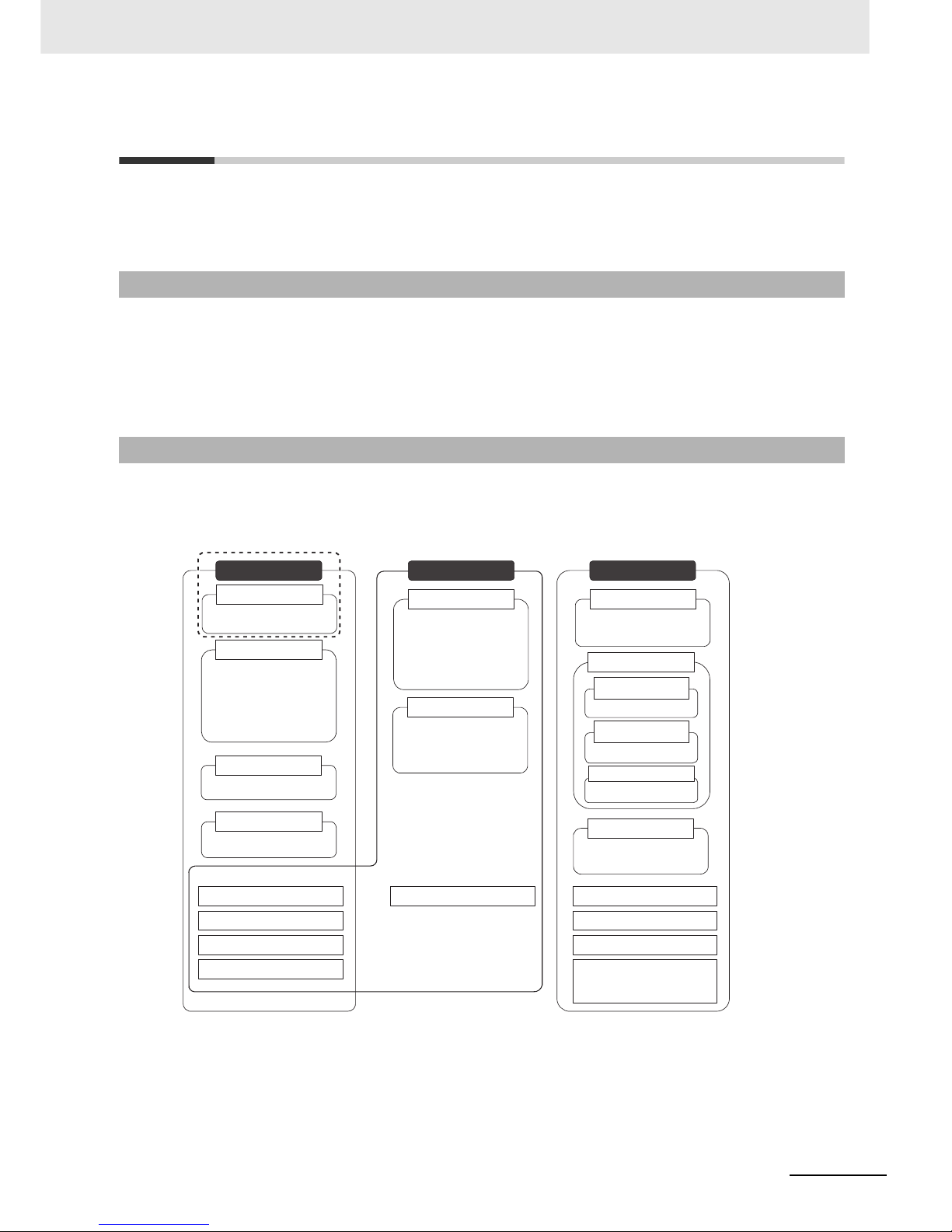
CJ2 CPU Unit Manuals
Information on the CJ2 CPU Units is provided in the following manuals. Refer to the appropriate manual
for the information that is required.
Mounting and Setting Hardware
1
2
3
4
5
6
7
Wiring
Connecting Online to the PLC
Software Setup
Creating the Program
Checking and Debugging Operation
Maintenance and Troubleshooting
CJ-series CJ2 CPU Unit Hardware User’s Manual (W472) CJ-series CJ2 CPU Unit Software User’s Manual (W473)
This Manual
CX-Programmer Support Software
Connecting Cables
Error codes and remedies if a problem
occurs
Procedures for connecting the
CX-Programmer Support Software
Software setting methods for the CPU Unit
(including I/O memory allocation, PLC Setup
settings, Special I/O Unit parameters, CPU Bus
Unit parameters, and routing tables. )
For details on built-in EtherNet/IP port, refer to
the EtherNet/IP Unit Operation Manual (W465)
• Checking I/O wiring, setting the Auxiliary Area
settings, and performing trial operation
• Monitoring and debugging with the
CX-Programmer
• Unit part names and specifications
• Basic system configuration
• Unit mounting procedure
• Setting procedure for DIP switch and rotary
switches on the front of the CPU Unit
For details on built-in EtherNet/IP port, refer
to the EtherNet/IP Unit Operation Manual
(W465)
• Wiring the Power Supply Unit
• Wring Basic I/O Units and external I/O
devices
• Program types and basic information
• CPU Unit operation
• Internal memory
• Data management using file memory in the
CPU Unit
• Built-in CPU functions
• Settings
For details on instructions, refer to the
Instructions Reference Manual (W474).
Page 9

3
CJ2 CPU Unit Hardware User’s Manual
The CJ2 CPU manuals are organized in the sections listed in the following tables. Refer to the appropriate section in the manuals as required.
Manual Configuration
Hardware User’s Manual (W472) (This Manual)
Section Content
Section 1 Overview
This section gives an overview of the CJ2 CPU Units and describes the features and
specifications.
Section 2 Basic System Configuration and Devices
This section describes the system configuration for the CJ2 CPU Unit.
Section 3 Nomenclature and
Functions
This section describes the part names and functions of the CPU Unit and Configuration
Units.
Section 4 Support Software
This section describes the types of Support Software to use to perform programming and
debugging and how to connect the PLC to the Support Software.
Section 5 Installation
This section describes the installation locations and how to wire CPU Units and Configuration Units.
Section 6 Troubleshooting
This section describes how to check the status for errors that occur during system operation and the remedies for those errors.
Section 7 Inspection and Maintenance
This section describes periodic inspection, the service lifes of the Battery and Power
Supply Unit, and how to replace the Battery.
Section 8 Backup Operations This section describes the procedure to back up PLC data.
Appendices
The appendices provide Unit dimensions, details on fatal and non-fatal errors, information on connecting to serial ports on the CPU Unit, the procedure for installing the USB
driver on a computer, and information on load short-circuit protection and line disconnection detection.
Software User’s Manual (W473)
Section Content
Section 1 Overview This section gives an overview of the CJ2 CPU Units and describes the features and
specifications.
Section 2 Internal Memory in the
CPU Unit
This section describes the types of memory in the CPU Unit and the data that is stored.
Section 3 CPU Unit Operation This section describes the internal operation of the CPU Unit.
Section 4 CPU Unit Initialization This section describes the initial setup of the CPU Unit.
Section 5 Understanding Program-
ming
This section describes program types and programming details, such as symbols and
programming instructions.
Section 6 I/O Memory Areas This section describes the I/O memory areas in the CPU Unit.
Section 7 File Operations This section describes the files that can be stored in the CPU Unit, the storage destina-
tion for those files, and file operations.
Section 8 I/O Allocations and Unit
Settings
This section describes the I/O allocations used to exchange data between the CPU Unit
and other Units.
Section 9 PLC Setup This section describes details on the PLC Setup settings, which are used to perform
basic settings for the CPU Unit.
Section 10 CPU Unit Functions This section describes functions that are built into the CPU Unit.
Section 11 Programming Devices
and Communications
This section describes the procedure for connecting the CJ2 CPU Unit to the CX-Pro-
grammer or other Support Software and to other devices.
Section 12 CPU Unit Cycle Time This section describes how to monitor and calculate the cycle time.
Appendices The appendices provide information on programming instructions, execution times, num-
ber of steps, Auxiliary Area words and bits, a memory map of the continuous PLC mem-
ory addresses, I/O memory operation when power is interrupted, and a comparison of
CJ-series and CS-series PLCs.
Page 10
4
CJ2 CPU Unit Hardware User’s Manual
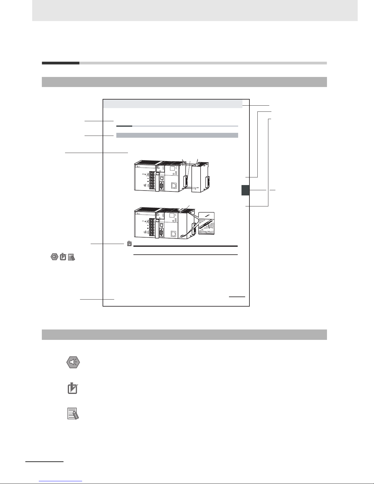
Manual Structure
The following page structure is used in this manual.
Special information in this manual is classified as follows:
Page Structure
Special Information
Precautions for Safe Use
Precautions on what to do and what not to do to ensure using the product safely.
Precautions for Correct Use
Precautions on what to do and what not to do to ensure proper operation and performance.
Additional Information
Additional information to increase understanding or make operation easier.
Level 1 heading
Level 2 heading
Level 3 heading
Level 2 heading
A step
in a procedure
Manual name
Level 3 heading
Page tab
Gives the current
headings.
Gives the number
of the section.
This illustration is provided only as a sample and may not literally appear in this manual.
Special Information
(See below.)
5-13
5 Installation
CJ2 CPU Unit Hardware User’s Manual
n
oita
lla
t
s
nI
2-
5
5
s
tn
e
n
o
p
moC CL
P
gn
it
ce
nnoC
1
-2
-
5
5-2 Installation
The Units that make up a CJ-series PLC can be connected simply by pressing the Units together and
locking the sliders by moving them toward the back of the Units. The End Cover is connected in the
same way to the Unit on the far right side of the PLC.
1. Join the Units so that the connectors fit exactly.
2. The yellow sliders at the top and bottom of each Unit lock the Units together. Move the sliders
toward the back of the Units as shown below until they click into place.
Precautions for Correct UsePrecautions for Correct Use
If the locking tabs are not secured properly, the connectors may become loose and not function
properly. Be sure to slide the locking tabs until they are securely in place.
5-2-1 Connecting PLC Components
Connector
Hook
Hook holes
Slider
Lock
Release
Move the sliders toward the back
until they lock into place.
Page 11

5
CJ2 CPU Unit Hardware User’s Manual
Sections in this Manual
1
2
3
4
5
6
7
8
A
1
2
3
4
5
6
7
8
A
Overview
Basic System Configuration and Devices
Nomenclature and Functions
Support Software
Installation
Troubleshooting
Inspection and Maintenance
Backup Operations
Appendices
Page 12

6
CJ2 CPU Unit Hardware User’s Manual
Page 13

7
CJ2 CPU Unit Hardware User’s Manual
CONTENTS
Introduction............................................................................................................... 1
CJ2 CPU Unit Manuals ............................................................................................. 2
Manual Structure ...................................................................................................... 4
Sections in this Manual............................................................................................ 5
Safety Precautions ................................................................................................. 15
Application Precautions......................................................................................... 21
Operating Environment Precautions .................................................................... 25
Regulations and Standards ................................................................................... 26
Related Manuals ..................................................................................................... 28
Section 1 Overview
1-1 Overview of CJ2 CPU Units ....................................................................................................1-2
1-1-1 Overview..................................................................................................................................... 1-2
1-1-2 CJ2 CPU Unit Features .............................................................................................................. 1-3
1-2 Basic Operating Procedure ....................................................................................................1-7
1-3 Specifications .......................................................................................................................... 1-8
1-3-1 General Specifications................................................................................................................ 1-8
1-3-2 Performance Specifications ........................................................................................................ 1-9
1-3-3 Function Specifications............................................................................................................. 1-13
Section 2 Basic System Configuration and Devices
2-1 Basic System Configuration...................................................................................................2-2
2-1-1 Basic System Configuration........................................................................................................ 2-2
2-1-2 CPU Rack................................................................................................................................... 2-3
2-1-3 Expansion Racks........................................................................................................................ 2-7
2-1-4 Configuration Units ................................................................................................................... 2-10
2-1-5 Calculating Unit Current Consumption ..................................................................................... 2-18
2-1-6 Calculating Power Consumption............................................................................................... 2-20
2-2 Expanded System Configuration ......................................................................................... 2-22
2-2-1 Serial Communications............................................................................................................. 2-22
2-2-2 Communications Networks....................................................................................................... 2-24
Section 3 Nomenclature and Functions
3-1 CPU Units ................................................................................................................................. 3-2
3-1-1 CPU Section ............................................................................................................................... 3-2
3-1-2 Built-in EtherNet/IP Section ........................................................................................................ 3-7
3-2 Memory Card.......................................................................................................................... 3-12
3-2-1 Models and Specifications........................................................................................................ 3-12
3-2-2 Operating Procedures............................................................................................................... 3-12
3-2-3 Installing and Removing ........................................................................................................... 3-13
Page 14

8
CJ2 CPU Unit Hardware User’s Manual
3-3 Power Supply Units ............................................................................................................... 3-16
3-3-1 Models and Specifications ........................................................................................................3-16
3-3-2 Components..............................................................................................................................3-19
3-3-3 Selecting a Power Supply Unit..................................................................................................3-21
3-4 CJ-series Basic I/O Units ...................................................................................................... 3-23
3-4-1 Basic I/O Units with Terminal Blocks.........................................................................................3-23
3-4-2 Thirty-two/Sixty-four-point Basic I/O Units with Connectors...................................................... 3-25
3-5 I/O Control Units and I/O Interface Units ............................................................................. 3-26
3-5-1 Component Names ...................................................................................................................3-26
3-5-2 System Configuration................................................................................................................3-26
Section 4 Support Software
4-1 Support Software..................................................................................................................... 4-2
4-1-1 CX-One FA Integrated Tool Package ..........................................................................................4-2
4-2 Connection Methods ............................................................................................................... 4-6
4-2-1 Connecting by USB.....................................................................................................................4-6
4-2-2 Connecting by RS-232C ............................................................................................................. 4-8
4-2-3 Connecting by Ethernet ............................................................................................................4-10
Section 5 Installation
5-1 Fail-safe Circuits...................................................................................................................... 5-2
5-2 Installation................................................................................................................................ 5-4
5-2-1 Installation and Wiring Precautions.............................................................................................5-4
5-2-2 Installation in a Control Panel .....................................................................................................5-6
5-2-3 Assembled Appearance and Dimensions ................................................................................... 5-8
5-2-4 Connecting PLC Components................................................................................................... 5-11
5-2-5 DIN Track Installation ................................................................................................................5-14
5-2-6 Connecting CJ-series Expansion Racks................................................................................... 5-16
5-3 Wiring ..................................................................................................................................... 5-19
5-3-1 Power Supply Wiring.................................................................................................................5-19
5-3-2 Wiring CJ-series Basic I/O Units with Terminal Blocks ............................................................. 5-25
5-3-3 Wiring Basic I/O Units with Connectors ....................................................................................5-27
5-3-4 Connecting to Connector-Terminal Block Conversion Units or I/O Relay Terminals .................5-31
5-3-5 Connecting I/O Devices ............................................................................................................5-32
5-3-6 Wiring with Ethernet Cable .......................................................................................................5-36
5-4 Control Panel Installation ..................................................................................................... 5-39
5-4-1 Temperature ..............................................................................................................................5-39
5-4-2 Humidity .................................................................................................................................... 5-41
5-4-3 Vibration and Shock..................................................................................................................5-41
5-4-4 Atmosphere............................................................................................................................... 5-41
5-4-5 Electrical Environment ..............................................................................................................5-42
5-4-6 Grounding .................................................................................................................................5-46
Section 6 Troubleshooting
6-1 CPU Unit Errors ....................................................................................................................... 6-2
6-1-1 Errors and Remedies ..................................................................................................................6-2
6-1-2 Checking Errors ..........................................................................................................................6-2
6-1-3 Checking Detailed Status............................................................................................................6-3
6-1-4 Reading Error Log Information....................................................................................................6-3
6-1-5 I/O Table Verification ...................................................................................................................6-5
6-1-6 Types of Errors ............................................................................................................................6-6
6-1-7 Handling Errors ...........................................................................................................................6-7
Page 15

9
CJ2 CPU Unit Hardware User’s Manual
6-2 Built-in EtherNet/IP Port Errors and Remedies................................................................... 6-23
6-2-1 Checking Built-in EtherNet/IP Port Error Status ....................................................................... 6-23
6-2-2 Checking Error Status at the EtherNet/IP Port Seven-segment Display................................... 6-24
6-3 Non-CPU Unit Errors and Remedies.................................................................................... 6-26
6-3-1 Error Causes and Remedies .................................................................................................... 6-26
Section 7 Inspection and Maintenance
7-1 Inspections............................................................................................................................... 7-2
7-1-1 Inspection Points ........................................................................................................................ 7-2
7-1-2 Unit Replacement Precautions ................................................................................................... 7-4
7-2 Replacing the Battery.............................................................................................................. 7-5
7-2-1 Battery Replacement .................................................................................................................. 7-5
7-2-2 Operation When Battery Is Exhausted or Not Installed .............................................................. 7-8
7-3 Power Supply Unit Replacement Time ................................................................................ 7-10
Section 8 Backup Operations
8-1 Backing Up Data ...................................................................................................................... 8-2
8-2 Using a Computer to Back Up Data ....................................................................................... 8-3
8-2-1 PLC Backup Tool ........................................................................................................................ 8-3
8-2-2 PLC Backup Tool Operations...................................................................................................... 8-4
8-3 Simple Backup......................................................................................................................... 8-7
8-3-1 Overview..................................................................................................................................... 8-7
8-3-2 Operating Procedures................................................................................................................. 8-8
8-3-3 Verifying Backup Operations with Indicators ............................................................................ 8-10
8-3-4 Related Auxiliary Bits/Words .................................................................................................... 8-12
8-3-5 Time Required for Simple Backup............................................................................................8-12
8-3-6 Data Backed Up Using Simple Backup..................................................................................... 8-12
Appendices
A-1 Specifications of Basic I/O Units ...........................................................................................A-2
A-1-1 Overview of Units........................................................................................................................A-2
A-1-2 Basic I/O Units............................................................................................................................A-4
A-1-3 Precautions on Contact Output Units .......................................................................................A-51
A-1-4 Connecting Connector-Terminal Block Conversion Units and I/O Relay Terminals.................. A-53
A-2 Dimensions ............................................................................................................................A-86
A-2-1 CJ2H CPU Units.......................................................................................................................A-86
A-2-2 Power Supply Units................................................................................................................... A-86
A-2-3 Basic I/O Units..........................................................................................................................A-89
A-2-4 I/O Control Unit and I/O Interface Unit......................................................................................A-92
A-2-5 I/O Memory Card ......................................................................................................................A-92
A-3 Fatal and Non-fatal Error Details..........................................................................................A-93
A-3-1 Fatal Errors...............................................................................................................................A-93
A-3-2 Non-fatal Errors ........................................................................................................................ A-98
A-4 Connecting to the RS-232C Serial Port on the CPU Unit .................................................A-101
A-4-1 RS-232C Port Specifications ..................................................................................................A-101
A-4-2 Connection Examples.............................................................................................................A-102
A-4-3 Applicable Connectors and Recommended Cables ...............................................................A-105
A-4-4 Example of Recommended RS-232C Wiring .........................................................................A-106
A-4-5 Wiring Connectors ..................................................................................................................A-107
A-5 Installing the USB Driver ....................................................................................................A-110
Page 16

10
CJ2 CPU Unit Hardware User’s Manual
A-6 Load Short-circuit Protection and Line Disconnection Detection for Basic I/O Units..A-115
A-6-1 Load Short-circuit Protection and Line Disconnection Detection for CJ1W-OD202................A-115
A-6-2 Load Short-circuit Protection for CJ1W-OD204/OD212/OD232/MD232.................................A-117
A-7 Relay Output Noise Reduction Methods ...........................................................................A-119
index................................................................................................................ Index-1
Page 17

11
CJ2 CPU Unit Hardware User’s Manual
Read and Understand this Manual
Please read and understand this manual before using the product. Please consult your OMRON representative
if you have any questions or comments.
Warranty and Limitations of Liability
WARRANTY
OMRON's exclusive warranty is that the products are free from defects in materials and workmanship for a
period of one year (or other period if specified) from date of sale by OMRON.
OMRON MAKES NO WARRANTY OR REPRESENTATION, EXPRESS OR IMPLIED, REGARDING NONINFRINGEMENT, MERCHANTABILITY, OR FITNESS FOR PARTICULAR PURPOSE OF THE
PRODUCTS. ANY BUYER OR USER ACKNOWLEDGES THAT THE BUYER OR USER ALONE HAS
DETERMINED THAT THE PRODUCTS WILL SUITABLY MEET THE REQUIREMENTS OF THEIR
INTENDED USE. OMRON DISCLAIMS ALL OTHER WARRANTIES, EXPRESS OR IMPLIED.
LIMITATIONS OF LIABILITY
OMRON SHALL NOT BE RESPONSIBLE FOR SPECIAL, INDIRECT, OR CONSEQUENTIAL DAMAGES,
LOSS OF PROFITS OR COMMERCIAL LOSS IN ANY WAY CONNECTED WITH THE PRODUCTS,
WHETHER SUCH CLAIM IS BASED ON CONTRACT, WARRANTY, NEGLIGENCE, OR STRICT
LIABILITY.
In no event shall the responsibility of OMRON for any act exceed the individual price of the product on which
liability is asserted.
IN NO EVENT SHALL OMRON BE RESPONSIBLE FOR WARRANTY, REPAIR, OR OTHER CLAIMS
REGARDING THE PRODUCTS UNLESS OMRON'S ANALYSIS CONFIRMS THAT THE PRODUCTS
WERE PROPERLY HANDLED, STORED, INSTALLED, AND MAINTAINED AND NOT SUBJECT TO
CONTAMINATION, ABUSE, MISUSE, OR INAPPROPRIATE MODIFICATION OR REPAIR.
Page 18

12
CJ2 CPU Unit Hardware User’s Manual
Application Considerations
SUITABILITY FOR USE
OMRON shall not be responsible for conformity with any standards, codes, or regulations that apply to the
combination of products in the customer's application or use of the products.
At the customer's request, OMRON will provide applicable third party certification documents identifying
ratings and limitations of use that apply to the products. This information by itself is not sufficient for a
complete determination of the suitability of the products in combination with the end product, machine,
system, or other application or use.
The following are some examples of applications for which particular attention must be given. This is not
intended to be an exhaustive list of all possible uses of the products, nor is it intended to imply that the uses
listed may be suitable for the products:
• Outdoor use, uses involving potential chemical contamination or electrical interference, or conditions or
uses not described in this manual.
• Nuclear energy control systems, combustion systems, railroad systems, aviation systems, medical
equipment, amusement machines, vehicles, safety equipment, and installations subject to separate
industry or government regulations.
• Systems, machines, and equipment that could present a risk to life or property.
Please know and observe all prohibitions of use applicable to the products.
NEVER USE THE PRODUCTS FOR AN APPLICATION INVOLVING SERIOUS RISK TO LIFE OR
PROPERTY WITHOUT ENSURING THAT THE SYSTEM AS A WHOLE HAS BEEN DESIGNED TO
ADDRESS THE RISKS, AND THAT THE OMRON PRODUCTS ARE PROPERLY RATED AND
INSTALLED FOR THE INTENDED USE WITHIN THE OVERALL EQUIPMENT OR SYSTEM.
PROGRAMMABLE PRODUCTS
OMRON shall not be responsible for the user's programming of a programmable product, or any
consequence thereof.
Page 19

13
CJ2 CPU Unit Hardware User’s Manual
Disclaimers
CHANGE IN SPECIFICATIONS
Product specifications and accessories may be changed at any time based on improvements and other
reasons.
It is our practice to change model numbers when published ratings or features are changed, or when
significant construction changes are made. However, some specifications of the products may be changed
without any notice. When in doubt, special model numbers may be assigned to fix or establish key
specifications for your application on your request. Please consult with your OMRON representative at any
time to confirm actual specifications of purchased products.
DIMENSIONS AND WEIGHTS
Dimensions and weights are nominal and are not to be used for manufacturing purposes, even when
tolerances are shown.
PERFORMANCE DATA
Performance data given in this manual is provided as a guide for the user in determining suitability and does
not constitute a warranty. It may represent the result of OMRON's test conditions, and the users must
correlate it to actual application requirements. Actual performance is subject to the OMRON Warranty and
Limitations of Liability.
ERRORS AND OMISSIONS
The information in this manual has been carefully checked and is believed to be accurate; however, no
responsibility is assumed for clerical, typographical, or proofreading errors, or omissions.
Page 20

14
CJ2 CPU Unit Hardware User’s Manual
Page 21
15
CJ2 CPU Unit Hardware User’s Manual
Safety Precautions
The following notation is used in this manual to provide precautions required to ensure safe usage of a
CJ-series PLC. The safety precautions that are provided are extremely important to safety. Always read
and heed the information provided in all safety precautions.
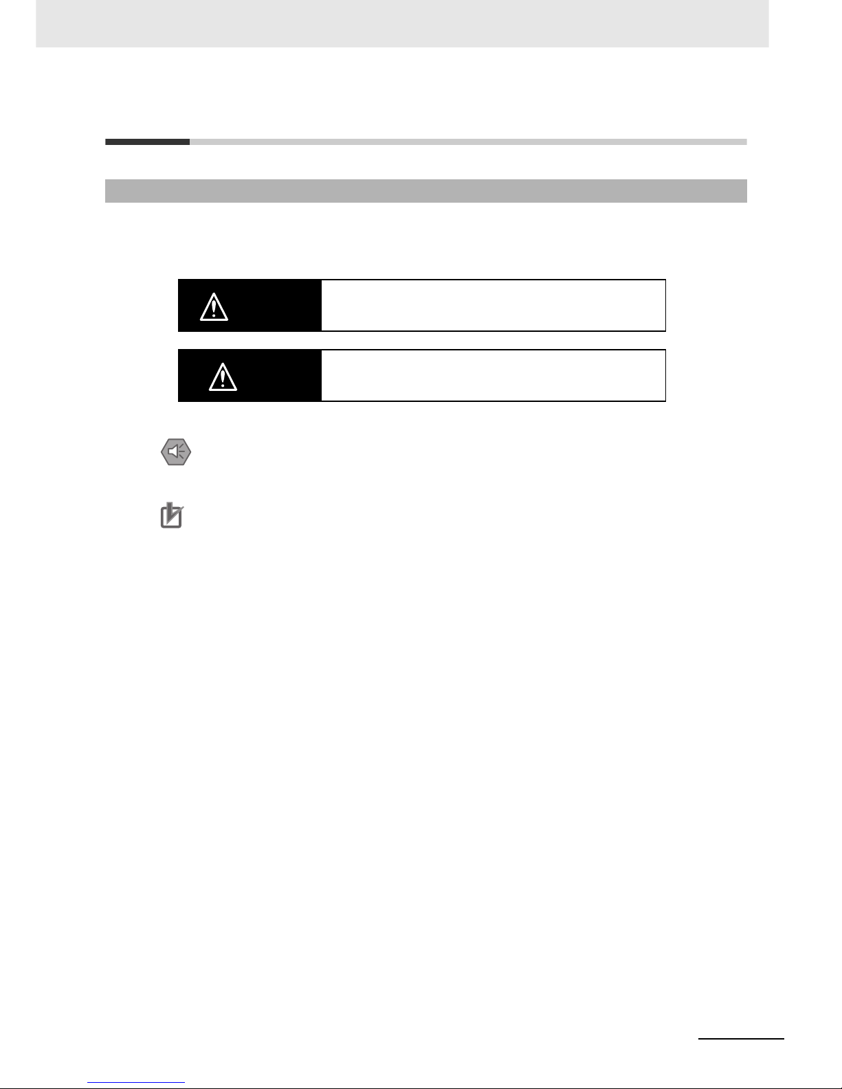
Definition of Precautionary Information
WARINING
Indicates an imminently hazardous situation which, if not
avoided, will result in death or serious injury. Additionally, there
may be severe property damage.
Caution
Indicates a potentially hazardous situation which, if not avoided,
may result in minor or moderate injury, or property damage.
Precautions for Safe Use
Indicates precautions on what to do and what not to do to ensure using the product safely.
Precautions for Correct Use
Indicates precautions on what to do and what not to do to ensure proper operation and performance.
Page 22
16
CJ2 CPU Unit Hardware User’s Manual
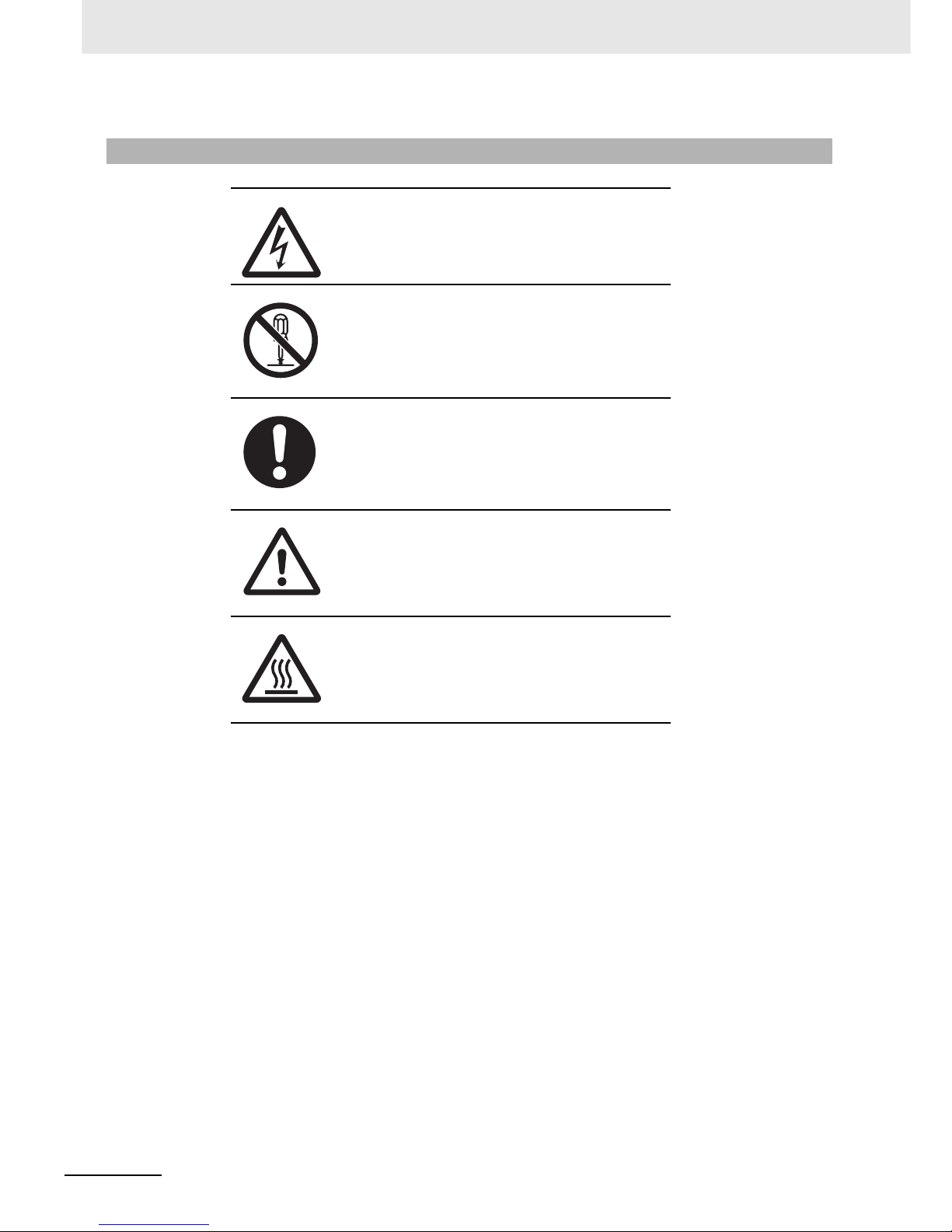
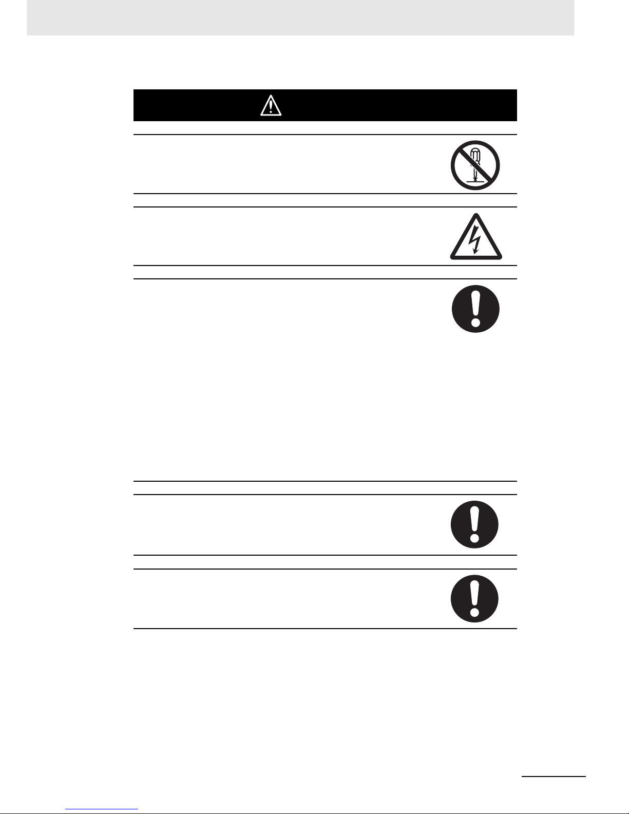
Symbols
The triangle symbol indicates precautions (including warnings).
The specific operation is shown in the triangle and explained in
text. This example indicates a precaution for electric shock.
The circle and slash symbol indicates operations that you must
not do. The specific operation is shown in the circle and
explained in text. This example indicates “do not disassemble.”
The filled circle symbol indicates operations that you must do.
The specific operation is shown in the circle and explained in
text. This example shows a general precaution for something
that you must do.
The triangle symbol indicates precautions (including warnings).
The specific operation is shown in the triangle and explained in
text. This example indicates a general precaution.
The triangle symbol indicates precautions (including warnings).
The specific operation is shown in the triangle and explained in
text. This example indicates a precaution for hot surfaces.
Page 23
17
CJ2 CPU Unit Hardware User’s Manual
WARNING
Do not attempt to take any Unit apart while the power is being supplied.
Doing so may result in electric shock.
Do not touch any of the terminals or terminal blocks while the power is being
supplied. Doing so may result in electric shock.
Provide safety measures in external circuits (i.e., not in the Programmable
Controller), including the following items, to ensure safety in the system if an
abnormality occurs due to malfunction of the PLC or another external factor
affecting the PLC operation. Not doing so may result in serious accidents.
• Emergency stop circuits, interlock circuits, limit circuits, and similar safety
measures must be provided in external control circuits.
• The PLC will turn OFF all outputs when its self-diagnosis function detects
any error or when a severe failure alarm (FALS) instruction is executed. As
a countermeasure for such errors, external safety measures must be provided to ensure safety in the system.
• The PLC outputs may remain ON or OFF due to deposition or burning of
the output relays or destruction of the output transistors. As a countermeasure for such problems, external safety measures must be provided to
ensure safety in the system.
• When the 24-VDC output (service power supply to the PLC) is overloaded
or short-circuited, the voltage may drop and result in the outputs being
turned OFF. As a countermeasure for such problems, external safety measures must be provided to ensure safety in the system.
Confirm safety before transferring data files stored in the file memory (Memory Card or EM file memory) to the I/O area (CIO) of the CPU Unit using a
peripheral tool. Otherwise, the devices connected to the output unit may malfunction regardless of the operation mode of the CPU Unit.
Fail-safe measures must be taken by the customer to ensure safety in the
event of incorrect, missing, or abnormal signals caused by broken signal
lines, momentary power interruptions, or other causes. Serious accidents
may result from abnormal operation if proper measures are not provided.
Page 24
18
CJ2 CPU Unit Hardware User’s Manual
WARNING
When restoring data, carefully check that the selected data is the correct
data to be restored before executing the restore operation. Depending on the
contents of the selected data, the control system may operate unexpectedly
after the data is restored.
Some Special I/O Units and CPU Bus Units operate with parameters stored
in the CPU Unit (e.g., words allocated in DM Area, data link tables, or Ethernet settings). Information on restrictions will be displayed in the Information
Area in the PLC Backup Tool if there are any restrictions for the selected
CPU Bus Unit or Special I/O Unit. Check the restrictions, and then be sure to
select both the CPU Unit and the CPU Bus Unit or Special I/O Unit when
backing up or restoring data. The control system may operate unexpectedly if
the equipment is started with the data backed up or restored without selecting both Units.
Information on restrictions will be displayed in the Information Area in the
PLC Backup Tool if the data to be stored includes a Unit that has restrictions
on backup. Check the information on restrictions and take the required countermeasures. The control system may operate unexpectedly when the equipment is operated after the data is restored
Before restoring data during PLC operation, be sure that there will be no
problem if PLC operation stops. If the PLC stops at an unexpected time, the
control system may operate unexpectedly.
Be sure to turn the PLC power supply OFF and then back ON after restoring
data. If the power is not reset, the system may not be updated with the
restored data, and the control system may operate unexpectedly.
Data on forced status can be backed up but it cannot be restored. Perform
the procedure to force-set or force-reset bits from the CX-Programmer as
required before starting operation after restoring data that includes forced
status. Depending on the difference in the forced status, the control system
may operate unexpectedly.
Page 25
19
CJ2 CPU Unit Hardware User’s Manual
Caution
Execute online edit only after confirming that no adverse effects will be
caused by extending the cycle time. Otherwise, the input signals may not be
readable.
Confirm safety at the destination node before transferring a program to
another node or changing contents of the I/O memory area. Doing either of
these without confirming safety may result in injury.
The CJ2 CPU Units automatically back up the user program and parameter
data to flash memory when these are written to the CPU Unit. I/O memory
including the DM, EM, and Holding Areas), however, is not written to flash
memory.
The DM, EM, and Holding Areas can be held during power interruptions with
a battery. If there is a battery error, the contents of these areas may not be
accurate after a power interruption. If the contents of the DM, EM, and Holding Areas are used to control external outputs, prevent inappropriate outputs
from being made whenever the Battery Error Flag (A402.04) is ON.
Tighten the screws on the terminal block of the AC Power Supply Unit to the
torque specified in the user’s manual. The loose screws may result in burning
or malfunction.
Do not touch the Power Supply Unit when power is being supplied or immediately after the power supply is turned OFF. The Power Supply Unit will be hot
and you may be burned.
Be careful when connecting personal computers or other peripheral devices
to a PLC to which is mounted a non-insulated Unit (CS1W-CLK1@/5@(-V1)
or CS1W-ETN01) connected to an external power supply. A short-circuit will
be created if the 24 V side of the external power supply is grounded and the
0 V side of the peripheral device is grounded. When connecting a peripheral
device to this type of PLC, either ground the 0 V side of the external power
supply or do not ground the external power supply at all.
Page 26

20
CJ2 CPU Unit Hardware User’s Manual
Caution
If a symbol or memory address (only symbols are allowed for ST programming) is specified for the suffix of an array variable in ladder or ST programming, be sure that the specified element number does not exceed the
maximum memory area range. For example, write the program so that processing is executed only when the indirect specification is within the memory
area range by using a symbol comparison instructions or an IF statement.
Specifying an element number that exceeds the maximum range of the
memory area specified for the symbol will result accessing data in a different
memory area, and may result in unexpected operation.
If a symbol or address is specified for an offset in a ladder diagram, program
so that the memory area of the start address is not exceeded when the offset
is specified indirectly using a word address or symbol. For example, write the
program so that processing is executed only when the indirect specification
does not cause the final address to exceed the memory area by using an
input comparison instruction or other instruction.
If a indirect specification causes the address to exceed the area of the start
address, the system will access data in other area, and unexpected operation may occur.
Page 27

21
CJ2 CPU Unit Hardware User’s Manual
Application Precautions
Observe the following precautions when using a CJ-series PLC.
z Power Supply
• Always use the power supply voltages specified in the user’s manuals. An incorrect voltage may
result in malfunction or burning.
• Exceeding the capacity of the Power Supply Unit may prevent the CPU Unit or other Units from
starting.
• Take appropriate measures to ensure that the specified power with the rated voltage and frequency is supplied. Be particularly careful in places where the power supply is unstable. An incorrect power supply may result in malfunction.
• Always turn OFF the power supply to the PLC before attempting any of the following. Not turning
OFF the power supply may result in malfunction or electric shock.
• Mounting or dismounting Power Supply Units, I/O Units, CPU Units, or any other Units.
• Assembling the Units.
• Setting DIP switches or rotary switches.
• Connecting cables or wiring the system.
• Connecting or disconnecting the connectors.
• When cross-wiring terminals, the total current for all the terminal will flow in the wire. Make sure
that the current capacity of the wire is sufficient.
• Observe the following precautions when using a Power Supply Unit that supports the Replacement Notification Function.
• Replace the Power Supply Unit within six months if the display on the front of the Power Supply Unit alternates between 0.0 and A02, or if the alarm output automatically turns OFF.
• Keep the alarm output cable separated from power line and high-voltage lines.
• Do not apply a voltage or connect a load exceeding the specifications to the alarm output.
• Whe storing the Power Supply Unit for more than three months, store it at −20 to 30°C and
25% to 70% humidity to preserve the Replacement Notification Function.
• If the Power Supply Unit is not installed properly, heat buildup may cause the replacement notification signal to appear at the wrong time or may cause interior elements to deteriorate or
become damaged. Use only the standard installation method.
• Do not touch the terminals on the Power Supply Unit immediately after turning OFF the power
supply. Residual voltage may cause electrical shock.
• Observe the following precautions to prevent failure due to difference in electrical potential if the
computer is connected to the PLC.
• Before connecting a laptop computer to the PLC, disconnect the power supply plug of the
computer from the AC outlet. Residual current in the AC adaptor may cause difference in electrical potential to occur between the computer and the PLC. After you connect the computer
and PLC, supply the power again from the AC adaptor.
• If the computer has a FG terminal, make the connections so that it has the same electrical
potential as the FG (GR) terminal on the PLC.
• If the computer is grounded to a separate location, difference in electrical potential may occur
depending on the grounding conditions.
z Installation
• Do not install the PLC near sources of strong high-frequency noise.
• Before touching a Unit, be sure to first touch a grounded metallic object in order to discharge any
static build-up. Not doing so may result in malfunction or damage.
Page 28

22
CJ2 CPU Unit Hardware User’s Manual
• Be sure that the connectors, terminal blocks, expansion cables, and other items with locking
devices are properly locked into place. Improper locking may result in malfunction.
• The sliders on the tops and bottoms of the Power Supply Unit, CPU Unit, I/O Units, Special I/O
Units, and CPU Bus Units must be completely locked (until they click into place) after connecting
to adjacent Units. The Unit may not operate properly if the sliders are not locked in place. It may
not be possible to achieve proper functionality if the sliders are not locked.
• Always attach the End Cover that comes with the CPU Unit to the right end of the CPU Rack. The
PLC will not operate correctly if the End Cover is not attached.
z Wiring
• Wire all connections correctly.
• Double-check all wiring and switch settings before turning ON the power supply. Incorrect wiring
may result in burning.
• Be sure that all terminal screws, and cable connector screws are tightened to the torque specified
in the relevant manuals. Incorrect tightening torque may result in malfunction.
• Do not apply a force exceeding 100 N to the terminal block when tightening it.
• Mount Units only after checking terminal blocks and connectors completely.
• Leave the label attached to the Unit when wiring. Removing the label may result in malfunction if
foreign matter enters the Unit.
• Remove the label after the completion of wiring to ensure proper heat dissipation. Leaving the
label attached may result in malfunction.
• Use crimp terminals for wiring. Do not connect bare stranded wires directly to terminals. Connection of bare stranded wires may result in burning.
• Do not apply voltages to the Input Units in excess of the rated input voltage. Excess voltages may
result in burning.
• Always connect to a ground of 100 Ω or less when installing the Units. Not connecting to a ground
of 100 Ω or less may result in electric shock.
• A ground of 100 Ω or less must be installed when shorting the GR and LG terminals on the Power
Supply Unit.
• Fail-safe measures must be taken by the customer to ensure safety in the event of incorrect, missing, or abnormal signals caused by broken signal lines, momentary power interruptions, or other
causes.
• Do not apply voltages or connect loads to the Output Units in excess of the maximum switching
capacity. Excess voltage or loads may result in burning.
• Do not pull on the cables or bend the cables beyond their natural limit. Doing either of these may
break the cables.
• Do not place objects on top of the cables or other wiring lines. Doing so may break the cables.
• Do not use commercially available RS-232C personal computer cables. Always use the special
cables listed in this manual or make cables according to manual specifications. Using commercially available cables may damage the external devices or CPU Unit.
• Never connect pin 6 (5-V power supply) on the RS-232C port on the CPU Unit to any device other
than an NT-AL001 or CJ1W-CIF11 Adapter. The external device or the CPU Unit may be damaged.
z Handling
• The Power Supply Unit may possibly be damaged if the entire voltage for a dielectric strength test
is applied or shut OFF suddenly using a switch. Use a variable resistor to gradually increase and
decrease the voltage.
• Separate the line ground terminal (LG) from the functional ground terminal (GR) on the Power
Supply Unit before performing withstand voltage tests or insulation resistance tests. Not doing so
may result in burning.
• Make sure that the DIP switches and DM Area are set correctly before starting operation.
Page 29

23
CJ2 CPU Unit Hardware User’s Manual
• Make sure that the required data for the DM Area, Holding Area, and other memory areas has
been transferred to a CPU Unit that has been replaced before restarting operation.
• Confirm that no adverse effect will occur in the system before attempting any of the following. Not
doing so may result in an unexpected operation.
• Changing the operating mode of the PLC (including the setting of the startup operating mode).
• Force-setting/force-resetting any bit in memory.
• Changing the present value of any word or any set value in memory.
• Do not attempt to disassemble, repair, or modify any Units. Any attempt to do so may result in malfunction, fire, or electric shock.
• Do not drop the PLC or subject abnormal vibration or shock to it.
• When replacing parts, be sure to confirm that the rating of a new part is correct. Not doing so may
result in malfunction or burning.
• When transporting or storing Units or Board, static electricity can destroy LSIs or ICs. Cover the
PCBs with a conductive material and maintain the specified storage temperature.
• Do not touch circuit boards or the components mounted to them with your bare hands. There are
sharp leads and other parts on the boards that may cause injury if handled improperly.
• The life of the battery will be reduced if a CPU Unit is left for a period of time without a battery
installed and without power supply, and then a battery is installed without turning ON the power
supply.
• Before replacing the battery, turn ON power for at least 5 minutes before starting the replacement
procedure and complete replacing the battery within 5 minutes of turning OFF the power supply.
Memory contents may be corrupted if this precaution is not obeyed.
• If the Battery Error Flag is used in programming the application, confirm system safety even if the
system detects a battery error before you replace the battery while the power is ON.
• Do not short the battery terminals or charge, disassemble, heat, or incinerate the battery. Do not
subject the battery to strong shocks. Doing any of these may result in leakage, rupture, heat generation, or ignition of the battery. Dispose of any battery that has been dropped on the floor or otherwise subjected to excessive shock. Batteries that have been subjected to shock may leak if they
are used.
• UL standards require that only an experienced engineer can replace the battery.
Make sure that an experienced engineer is in charge of battery replacement. Follow
the procedure for battery replacement given in this manual.
• Unexpected operation may result if inappropriate data link tables or parameters are set. Even if
appropriate data link tables and parameters have been set, confirm that the controlled system will
not be adversely affected before starting or stopping data links.
• CPU Bus Units will be restarted when routing tables are transferred from a Programming Device
to the CPU Unit. Restarting these Units is required to read and enable the new routing tables.
Confirm that the system will not be adversely affected before allowing the CPU Bus Units to be
reset.
• When creating an AUTOEXEC.IOM file from a Programming Device (a Programming Console
or the CX-Programmer) to automatically transfer data at startup, set the first write address to
D20000 and be sure that the size of data written does not exceed the size of the DM Area.
When the data file is read from the Memory Card at startup, data will be written in the CPU
Unit starting at D20000 even if another address was set when the AUTOEXEC.IOM file was
created. Also, if the DM Area is exceeded (which is possible when the CX-Programmer is
used), the remaining data will be written to the EM Area.
• A battery is mounted to a CJ-series CPU Unit when the Unit is shipped from the factory. Also, the
time is set on the internal clock. It is thus not necessary to clear memory and set the clock before
using a CJ-series CPU Unit. This point differs from the CS-series CS1 CPU Units.
Page 30

24
CJ2 CPU Unit Hardware User’s Manual
• The user program and parameter area data in the CJ2 CPU Units are backed up in the built-in
flash memory. The BKUP indicator will light on the front of the CPU Unit when the backup operation is in progress. Do not turn OFF the power supply to the CPU Unit when the BKUP indicator is
lit. The data will not be backed up if power is turned OFF.
• Check the user program and Unit parameter settings for proper execution before actually running
them on the Unit. Not checking the program and parameter settings may result in an unexpected
operation.
• When setting a Special I/O Unit or CPU Bus Unit in the I/O tables, carefully check the safety of the
devices at the connection target before restarting the Unit.
• A CS1 or CJ1 CPU Unit program file (.OBJ) cannot be transferred directly to a CJ2 CPU Unit
using a Memory Card. It must first be converted for use with a CJ2 CPU Unit using the CX-Programmer.
z External Circuits
• Interlock circuits, limit circuits, and similar safety measures in external circuits (i.e., not in the Programmable Controller) must be provided by the customer.
• Always turn ON power to the PLC before turning ON power to the control system. If the PLC
power supply is turned ON after the control power supply, temporary errors may result in control
system signals because the output terminals on DC Output Units and other Units will momentarily
turn ON when power is turned ON to the PLC.
• Fail-safe measures must be taken by the customer to ensure safety in the event that outputs from
Output Units remain ON as a result of internal circuit failures, which can occur in relays, transistors, and other elements.
• If the I/O Hold Bit is turned ON, the outputs from the PLC will not be turned OFF and will maintain
their previous status when the PLC is switched from RUN or MONITOR mode to PROGRAM
mode. Make sure that the external loads will not produce dangerous conditions when this occurs.
(When operation stops for a fatal error, including those produced with the FALS(007) instruction,
all outputs from Output Unit will be turned OFF and only the internal output status will be maintained.)
• Install external breakers and take other safety measures against short-circuiting in external wiring.
Insufficient safety measures against short-circuiting may result in burning.
• Dispose of the product and batteries according to local ordinances as they apply.
• Do not turn OFF the power supply to the PLC when reading or writing a Memory Card. Also, do
not remove the Memory Card when the BUSY indicator is lit. Doing so may make the Memory
Card unusable.
• To remove a Memory Card, first press the memory card power supply switch and then wait for the
BUSY indicator to go out before removing the Memory Card.
Page 31

25
CJ2 CPU Unit Hardware User’s Manual
Operating Environment Precautions
z Follow the instructions in this manual to correctly perform installation.
z Do not operate the control system in the following locations:
• Locations subject to direct sunlight.
• Locations subject to temperatures or humidity outside the range specified in the specifications.
• Locations subject to condensation as the result of severe changes in temperature.
• Locations subject to corrosive or flammable gases.
• Locations subject to dust (especially iron dust) or salts.
• Locations subject to exposure to water, oil, or chemicals.
• Locations subject to shock or vibration.
z Take appropriate and sufficient countermeasures when installing systems in the
following locations:
• Locations subject to static electricity or other forms of noise.
• Locations subject to strong electromagnetic fields.
• Locations subject to possible exposure to radioactivity.
• Locations close to power supplies.
Page 32

26
CJ2 CPU Unit Hardware User’s Manual
Regulations and Standards
• EMC Directives
• Low Voltage Directive
z EMC Directives
OMRON devices that comply with EC Directives also conform to the related EMC standards so that
they can be more easily built into other devices or the overall machine. The actual products have
been checked for conformity to EMC standards (see the following note). Whether the products conform to the standards in the system used by the customer, however, must be checked by the customer.
EMC-related performance of the OMRON devices that comply with EC Directives will vary depending on the configuration, wiring, and other conditions of the equipment or control panel on which the
OMRON devices are installed.
The customer must, therefore, perform the final check to confirm that devices and the overall
machine conform to EMC standards.
* Applicable EMC (Electromagnetic Compatibility) standards are as follows:
EMS (Electromagnetic Susceptibility):
CS Series: EN 61131-2 and EN 61000-6-2
CJ Series: EN 61000-6-2
* EMI (Electromagnetic Interference):
EN 61000-6-4 (Radiated emission: 10-m regulations)
z Low Voltage Directive
Always ensure that devices operating at voltages of 50 to 1,000 V AC and 75 to 1,500 V DC meet
the required safety standards for the PLC (EN 61131-2).
z Conformance to EC Directives
The CJ-series PLCs comply with EC Directives. To ensure that the machine or device in which the
CJ-series PLC is used complies with EC Directives, the PLC must be installed as follows:
• The CJ-series PLC must be installed within a control panel.
• You must use reinforced insulation or double insulation for the DC power supplies connected to
DC Power Supply Units and I/O Units.
• CJ-series PLCs complying with EC Directives also conform to the Common Emission Standard
(EN 61000-6-4). Radiated emission characteristics (10-m regulations) may vary depending on the
configuration of the control panel used, other devices connected to the control panel, wiring, and
other conditions. You must therefore confirm that the overall machine or equipment complies with
EC Directives.
This product conforms to the following shipbuilding standards. Applicability to the shipbuilding standards is based on certain usage conditions. It may not be possible to use the product in some locations. Contact your OMRON representative before attempting to use a PLC on a ship.
Conformance to EC Directives
Applicable Directives
Concepts
Conformance to Shipbuilding Standards
Page 33

27
CJ2 CPU Unit Hardware User’s Manual
z Usage Conditions for Applications Other Than on the Bridge or Deck
• The PLC must be installed in a control panel.
• Gaps in the door to the control panel must be completely filled or covered with gaskets or other
material.
z Usage Conditions for Bridge and Deck (Certified Only by NK)
• The PLC must be installed in a control panel.
• Gaps in the door to the control panel must be completely filled or covered with gaskets or other
material.
• The following noise filter must be connected to the power supply line.
Noise Filter
SYSMAC is a registered trademark for Programmable Controllers made by OMRON Corporation.
CX-One is a registered trademark for Programming Software made by OMRON Corporation.
Windows is a registered trademark of Microsoft Corporation.
Other system names and product names in this document are the trademarks or registered trademarks
of their respective companies.
Usage Conditions for NK and LR Shipbuilding Standards
Manufacturer Cosel Co., Ltd.
Model TAH-06-683
Trademarks
Page 34

28
CJ2 CPU Unit Hardware User’s Manual
Related Manuals
Manuals related to a PLC built using a CJ-series CJ2 CPU Unit are listed in the following table. Use
these manuals for reference.
Manual Cat. No. Model Application Description
CJ-series CJ2 CPU
Unit Hardware
User’s Manual (this
manual)
W472 CJ2H-CPU@@-EIP Hardware specifications for
CJ2 CPU Units
Describes the following for CJ2 CPU Units:
• Overview and features
• Basic system configuration
• Part nomenclature and functions
• Mounting and setting procedure
• Remedies for errors
• Also refer to the Software User’s Manual
(W473).
CJ-series CJ2 CPU
Unit Software User’s
Manual
W473 CJ2H-CPU@@-EIP Software specifications for
CJ2 CPU Units
Describes the following for CJ2 CPU Units:
• CPU Unit operation
• Internal memory
• Programming
• Settings
• Functions built into the CPU Unit
Also refer to the Hardware User’s Manual
(W472)
EtherNet/IP Units
Operation Manual
W465 CJ2H-CPU@@-EIP
CS1W-EIP21
CJ1W-EIP21
Using the built-in EtherNet/IP port of the CJ2 CPU
Unit
Describes the built-in EtherNet/IP port and EtherNet/IP Units.
Describes basic settings, tag data links, FINS
communications, and other functions.
CS/CJ/NSJ-series
Instructions Reference Manual
W474 CJ2H-CPU@@-EIP
CS1G/H-CPU@@H
CS1G/H-CPU@@-V1
CJ1G/H-CPU@@H
CJ1G-CPU@@
CJ1M-CPU@@
NSJ@-@@@@(B)-G5D
NSJ@-@@@@(B)-M3D
Information on instructions Describes each programming instruction in
detail.
Also refer to the Software User’s Manual (W473)
when you do programming.
CS/CJ/CP/NSJseries Communications Command Reference Manual
W342 CS1G/H-CPU@@H
CS1G/H-CPU@@-V1
CS1D-CPU@@H
CS1D-CPU@@S
CS1W-SCU@@-V1
CS1W-SCB@@-V1
CJ1H-CPU@@H-R
CJ1G/H-CPU@@H
CJ1G-CPU@@P
CJ1M-CPU@@
CJ1G-CPU@@
CJ1W-SCU@@-V1
CP1H-X@@@@-@
CP1H-XA@@@@-@
CP1H-Y@@@@-@
NSJ@-@@@@(B)-G5D
NSJ@-@@@@(B)-M3D
Information on communications for CS/CJ/CPseries CPU Units and NSJseries Controllers
Describes C-mode commands and FINS commands
Refer to this manual for a detailed description of
commands for communications with the CPU
Unit using C mode commands or FINS commands.
Note This manual describes the communica-
tions commands that are addressed to
CPU Units. The communications path that
is used is not relevant and can include any
of the following: serial ports on CPU Units,
communications ports on Serial Communications Units/Boards, and Communications Units. For communications
commands addressed to Special I/O Units
or CPU Bus Units, refer to the operation
manual for the related Unit.
CX-One Setup Manual
W463 CXONE-AL@@C-
V3/AL@@D-V3
Installing software from the
CX-One
Provides an overview of the CX-One FA Integrated Tool Package and describes the installation procedure.
CX-Programmer
Operation Manual
W446 WS02-CX@@-V@ Support Software for Win-
dows computers
CX-Programmer operating
procedure
Describes operating procedures for the CX-Programmer.
Also refer to the Software User’s Manual (W473)
and Instructions Reference Manual (W474)
when you do programming.
CX-Programmer
Operation Manual
Functions Blocks
W447
CX-Programmer
Operation Manual
SFC Programming
W469
Page 35

29
CJ2 CPU Unit Hardware User’s Manual
CS/CJ/CP/NSJseries CX-Simulator
Operation Manual
W366 WS02-SIMC1-E Operating procedures for
CX-Simulator Simulation
Support Software for Windows computers
Using simulation in the CXProgrammer with CX-Programmer version 6.1 or
higher
Describes the operating procedures for the CXSimulator.
When you do simulation, also refer to the CX-
Programmer Operation Manual (W446), Software User’s Manual (W473), and Instructions
Reference Manual (W474).
CS/CJ/CP/NSJseries CX-Integrator
Network Configuration Software Operation Manual
W464 CXONE-AL@@C-V3/
CXONE-AL@@D-V3
Network setup and monitoring
Describes the operating procedures for the CXIntegrator.
Manual Cat. No. Model Application Description
Page 36

30
CJ2 CPU Unit Hardware User’s Manual
Page 37

1-1
CJ2 CPU Unit Hardware User’s Manual
1
This section provides an overview of the CJ2 PLCs.
1-1 Overview of CJ2 CPU Units ...................................................................................................1-2
1-1-1 Overview .................................................................................................................................... 1-2
1-1-2 CJ2 CPU Unit Features ............................................................................................................. 1-3
1-2 Basic Operating Procedure ...................................................................................................1-7
1-3 Specifications ......................................................................................................................... 1-8
1-3-1 General Specifications ............................................................................................................... 1-8
1-3-2 Performance Specifications ....................................................................................................... 1-9
1-3-3 Function Specifications ............................................................................................................ 1-13
Overview
Page 38

1 Overview
1-2
CJ2 CPU Unit Hardware User’s Manual
1-1 Overview of CJ2 CPU Units
The SYSMAC CJ2 CPU Units are high-speed multi-functional CPU Units with a large memory capacity.
They provide the following features.
z Fast, with Large Memory Capacity
Basic performance is faster and memory capacity has been increased to provide ample capability
for machine control.
z Built-in EtherNet/IP Port
The CJ2 CPU Units support the EtherNet/IP open network as a standard feature. Support Software
connection and universal Ethernet communications, such as data links between PLCs, message
communications between PLCs, and FTP transfers, are all possible.
z General-purpose Networks for Support Software Interface
Support Software and devices can be easily connected using commercially available cable to general-purpose networks via USB and EtherNet/IP ports.
z Tag Access
CJ2 CPU Units have a tag name server to manage tag names and I/O addresses. This enables
access from external devices using tag names, without needing to know the I/O addresses.
z Easier Programming
CJ2 CPU Units offer a highly readable programming environment, including features such as
addressing DM and EM Area bits, setting address offsets, and using array variables.
z Improved Debugging
Online editing and data tracing have been improved, greatly increasing the efficiency of debugging.
1-1-1 Overview
Tag access
Easier programming
General-purpose networks for
Support Software interface
Built-in EtherNet/IP port:
standard equipment
Improved debugging
Faster, with
greater capacity
Page 39

1-3
1 Overview
CJ2 CPU Unit Hardware User’s Manual
1-1 Overview of CJ2 CPU Units
1
1-1-2 CJ2 CPU Unit Features
z High-speed Processing
High-speed processing times of 0.016 µs for basic instructions, 0.048 µs for special instructions, and
0.99 µs for immediate refreshing, are now possible.
z Large Program Capacity
The CJ2 CPU Units provide a large program capacity of up to 400 Ksteps.
z Large Data Memory Capacity
The CJ2 CPU Units provide a large EM Area capacity of up to 800 Kwords (25 banks).
z Up to 128 Cyclic Tasks
The user program can be divided into up to 128 tasks. Using smaller task programs makes it easier
to structure programs and contributes to shorter cycle times.
The CJ2 CPU Units provide as standard equipment a built-in EtherNet/IP port that supports the same
FINS Ethernet functions as an Ethernet Unit (including features such as a FINS server and time coordination) as well as the EtherNet/IP open network.
z High-speed, High-capacity Data Links with User-set Refresh Cycles
The CJ2 CPU Units provide high-speed, high-capacity data links, and refresh cycles can be set individually for each data link area.
In addition, using the EtherNet/IP DataLink Tool makes it possible to set the data links using an interface similar to that of the Controller Link automatic data link setup.
1-1-2 CJ2 CPU Unit Features
Fast, with Large Memory Capacity
Built-in EtherNet/IP Port
EtherNet/IP
High speed
The refresh cycle can be set individually for each area.
High capacity
CJ2 CPU Unit
CJ2 CPU Unit
Page 40

1 Overview
1-4
CJ2 CPU Unit Hardware User’s Manual
z Built-in USB and EtherNet/IP Ports
Commercially available USB cable can be used to connect directly from a USB port on a personal
computer. In addition, a PLC on the EtherNet/IP network can be accessed via USB.
z Prevent Connecting to the Wrong PLC by Using PLC Names from Support
Software
A user-set PLC name can be recorded in a CJ2 CPU Unit. When using Support Software to connect
online to a PLC, verification of the PLC name prevents incorrect connections from the Support Software.
z Network Symbols (Tags) for Flexible Support of Program Changes
The CJ2 CPU Units support network symbols (tags). They have an internal tag name server that
enables them to store tag names and addresses in advance in symbol tables in the CPU Units. Tags
enable the following features.
Data links can be set using tags.
With data links on an EtherNet/IP network, send and receive areas can be specified using symbols
rather than addresses. This enables flexible support for design changes by allowing the data link
areas set by tags to remain unchanged, while simply changing the symbol tables that contain the tag
names and addresses.
Access from host devices is enabled using tags.
Tags can be used for access from host devices, such as touch panel NS-series Programmable Terminals. This makes the creation of host screens and programs at devices such as PTs much more
convenient.
General-purpose Networks for Support Software Interface
Tag Access
Data links enabled by names
EtherNet/IP
Examples:
Inputs from a to b
Inputs from c to d
CJ2 CPU Unit
CJ2 CPU Unit
EtherNet/IP
Touch Panel
NS-series PT
Examples:
Writing to a
Reading from b
Middleware
Supporting EtherNet/IP
CJ2 CPU Unit
CJ2 CPU Unit
Host application, such as SCADA
Access is possible using tags.
Page 41

1-5
1 Overview
CJ2 CPU Unit Hardware User’s Manual
1-1 Overview of CJ2 CPU Units
1
1-1-2 CJ2 CPU Unit Features
Automatic tag allocation makes it unnecessary to know the addresses.
Automatic allocation of tags in the high-capacity EM Area, using automatic address allocation in CXProgrammer symbol tables, enables data link design and access from host devices without having to
pay attention to addresses.
z Address offsets can be specified.
When an address is specified for an instruction operand, an offset can be specified in brackets after
the address to offset it. For example, by setting a word address in brackets to specify the offset, the
address can be dynamically specified according to the contents of that word.
Example
W0.00[D0]: W0.00 is the starting address and the contents of D0 is the offset. If D0 is &3, then
W0.03 is specified.
z Symbols can be specified for array variable subscripts.
By specifying symbols for array variable subscripts, elements can be dynamically specified according to the values of the symbols.
Example
a[b]: The value of symbol b specifies the element for array variable a[ ].
z Bit addresses can be used in the DM Area and EM Area.
Previously the DM Area and the EM Area could be addressed only by words, and bit addresses
could not be specified. The work area for bits can now be expanded by enabling bit addresses in the
DM and EM Areas.
For example, D10.00 specifies bit 00 of D10.
z The format for timer/counter PV refreshing can be selected individually for
each instruction.
Either BCD or binary can be selected individually for each instruction as the format for timer/counter
PV refreshing. For example, the TIM (BCD) and TIMX (binary) instructions can be used together.
Easier Programming
PE
RIFH
ER
A
L
E
R
R
/A
L
M
R
U
N
IN
H
C
O
M
M
B
K
U
P
P
R
P
H
L
C
O
N
TR
OLLE
R
CP
U
6
4-
E
IP
CJ2H
S
Y
S
M
A
C
P
R
O
G
R
A
M
MAB
L
E
PORT
OPEN
B
U
SY
MCP
W
R
N
S
M
S
C
O
M
M
10M
100
M
Tags are allocated in
a high-capacity area.
Designing is performed
by using only tags,
with no need to pay
attention to addresses.
EtherNet/IP
Specified by tag a.
CJ2 CPU Unit
Page 42

1 Overview
1-6
CJ2 CPU Unit Hardware User’s Manual
z The optimum languages can be combined for structured programming.
Ladder diagrams, ST, and SFC languages can be freely combined in the user program. Being able
to use the optimum languages for a particular process helps reduce the time involved in programming.
In addition, ladder diagrams and ST language can be freely used for function blocks (FBs) in ladder
diagrams and ST programs, and for transition and action programs in SFC. This feature makes it
possible to optimize structured programming.
z Reduced Effect on Cycle Time from Online Editing
The additional cycle time due to online editing has been reduced to approx. 1 ms, minimizing the
effects on equipment operation during debugging.
z Fast, High-capacity Data Tracing
Up to 32 Kwords of data can be traced (8 time more than previously), with ample trigger conditions,
and data can be traced continuously for long periods of time.
Improved Debugging
User program
Task
Task
Task
Task
SFC
Step progression control
Ladder diagram
Control of equipment
and external devices
ST
Math processing
a := a + 1;
The programming language
suited to the process can be used.
Transition and action
programs in SFC
Ladder diagram
ST
FB_(A:=B,C=>D);
a := a + 1;
The programming
language suited to
the process can
be used.
FB in ladder diagram
FB in ST program
Page 43

1-7
1 Overview
CJ2 CPU Unit Hardware User’s Manual
1-2 Basic Operating Procedure
1
1-1-2 CJ2 CPU Unit Features
1-2 Basic Operating Procedure
In general, use the following procedure.
1. Setting Devices and Hardware
2. Wiring
3. Connecting Online to the PLC
4. I/O Allocations
5. Software Setup
6. Creating the Program
8. Basic Program Operation
Wire the power supply, I/O, and communications. Refer to the following manuals.
Connect the personal computer online to the PLC.
Using the CX-Programmer, allocate I/O memory in the CPU Unit to the mounted Units.
Make the PLC software settings.
Create the program using the CX-Programmer.
7. Checking Operation
Set the operating mode to RUN mode to start operation.
Mount the Power Supply Unit, the CPU Unit, the other Units, and the End Covers. Set the DIP switch
and rotary switches as required.
Refer to Section 3 Nomenclature and Functions and Section 5 Installation in the CJ2 CPU Unit
Hardware Operation Manual (Cat. No. W472).
Refer to Section 5 Installation in the CJ2 CPU Unit Hardware Operation Manual (Cat. No. W472).
Refer to Section 11 Programming Devices and Communications in the CJ2 CPU Unit Software
Operation Manual (Cat. No. W473).
Refer to Section 4 Support Software in the CJ2 CPU Unit Hardware Operation Manual (Cat. No.
W472)
Refer to Section 8 I/O Allocations and Unit Settings in the CJ2 CPU Unit Software Operation
Manual (Cat. No. W473)
• CPU Unit initialization: Refer to Section 4 CPU Unit Initialization in the CJ2 CPU Unit
Software Operation Manual (Cat. No. W473).
• DM Area Settings for Special I/O Units and CPU Bus Units: Refer to Section 8 I/O Allocations
and Unit Settings in the CJ2 CPU Unit Software Operation Manual (Cat. No. W473).
• PLC Setup: Refer to Section 9 PLC Setup in the CJ2 CPU Unit Software Operation Manual
(Cat. No. W473).
Refer to Section 5 Programming in the CJ2 CPU Unit Software Operation Manual (Cat. No.
W473).
Refer to 10-7 Debugging in the CJ2 CPU Unit Software Operation Manual (Cat. No. W473).
Check the I/O wiring and the AR Area settings, and perform trial operation. The CX-Programmer can
be used for monitoring and debugging.
Page 44

1 Overview
1-8
CJ2 CPU Unit Hardware User’s Manual
1-3 Specifications
1-3-1 General Specifications
Item
CJ2H-
CPU64-EIP CPU65-EIP CPU66-EIP CPU67-EIP CPU68-EIP
Enclosure Mounted in a panel
Grounding Less than 100 Ω
CPU Rack Dimensions 90 mm x 65 mm x 80 mm (W x H x D)
Weight 280 g or less
Current Consumption 5 VDC, 0.82 A
Use Environment Ambient Operating Temperature 0 to 55°C
Ambient Operating Humidity 10% to 90%
Atmosphere Must be free from corrosive gases.
Ambient Storage Temperature −20 to 70°C (excluding battery)
Altitude 2,000 m or less
Pollution Degree 2 or less: Conforms to JIS B3502 and IEC 61131-2.
Noise Immunity 2 kV on power supply line (Conforms to IEC 61000-4-4.)
Overvoltage Category Category II: Conforms to JIS B3502 and IEC 61131-2.
EMC Immunity Level Zone B
Vibration Resistance Conforms to JIS C60068-2-6.
Acceleration of 9.8 m/s
2
for 100 min in X, Y, and Z directions (10 sweeps of 10 min
each = 100 min total)
Shock Resistance Conforms to JIS C60068-2-27.
147 m/s
2
, 3 times in X, Y, and Z directions (100 m/s2 for Relay Output Units)
Battery Life 5 years at 25°C
Model CJ1W-BAT01
Applicable Standards Conforms to cULus and EC Directives.
Page 45

1-9
1 Overview
CJ2 CPU Unit Hardware User’s Manual
1-3 Specifications
1
1-3-2 Performance Specifications
1-3-2 Performance Specifications
Items
CJ2H-
CPU64-EIP CPU65-EIP CPU66-EIP CPU67-EIP CPU68-EIP
User Memory 50K steps 100K steps 150K steps 250K steps 400K steps
I/O Bits 2,560 bits
Processing
Speed
Overhead Processing Time Normal Mode: 200 µs
(If tag data links are used with EtherNet/IP, add the following to the above time: 100 µs + Number of
transferred words × 0.33 µs)
Execution Time Basic Instructions: 0.016 µs min.;
Special Instructions: 0.048 µs min.
Interrupt Task Start Time 30 µs
Maximum Number of Connectable Units Total per CPU Rack or Expansion Rack: 10 Units max.;
Total per PLC: 40 Units max.
Maximum Number of Expansion Racks 3 max.
CIO Area I/O Area 2,560 bits (160 words): Words CIO 0000 to CIO 0159
Link Area 3,200 bits (200 words): Words CIO 1000 to CIO 1199
CPU Bus Unit Area 6,400 bits (400 words): Words CIO 1500 to CIO 1899
Special I/O Unit Area 15,360 bits (960 words): Words CIO 2000 to CIO 2959
DeviceNet Area 9,600 bits (600 words): Words CIO 3200 to CIO 3799
Internal I/O Area 3,200 bits (200 words): Words CIO 1300 to CIO 1499
37,504 bits (2,344 words): Words CIO 3800 to CIO 6143
Cannot be used for external I/O.
Work Area 8,192 bits (512 words): Words W000 to W511
Cannot be used for external I/O.
Holding Area 8,192 bits (512 words): Words H000 to H511
Bits in this area maintain their ON/OFF status when PLC is turned OFF or operating mode is changed.
Words H512 to H1535: These words can be used only for function blocks. They can be used only for
function block instances (i.e., they are allocated only for internal variables in function blocks).
Auxiliary Area Read-only: 31,744 bits (1,984 words)
• 7,168 bits (448 words): Words A0 to A447
• 24,576 bits (1,536 words): Words A10000 to A11535
Read/write: 16,384 bits (1,024 words) in words A448 to A1471
Temporary Area 16 bits: TR0 to TR15
Timer Area 4,096 timer numbers (T0000 to T4095 (separate from counters))
Counter Area 4,096 counter numbers (C0000 to C4095 (separate from timers))
DM Area 32k words (Bits in the DM Area can be addressed either by bit or by word.)
DM Area words for Special I/O Units: D20000 to D29599 (100 words × 96 Units)
DM Area words for CPU Bus Units: D30000 to D31599 (100 words × 16 Units)
EM Area 32k words/1 bank × 25 banks max.: E00_00000 to E18_32767 max.
(Bits in the EM Area can be addressed either by bit or by word.)
32k × 4 banks 32k × 4 banks 32k × 10 banks 32k × 15 banks 32k × 25 banks
Force-set/reset
Enabled Banks
EM3 EM3 EM6 to EM9 EM7 to EME EM11 to EM18
Force-setting/resetting is enabled only for areas specified for automatic address allocation.
Index Registers IR0 to IR15
These are special registers for storing PLC memory addresses for indirect addressing. (Index Registers
can be set so that they are unique in each task or so that they are shared by all tasks.)
Cyclic Task Flag Area 128 flags
Memory Card 128 MB, 256 MB, or 512 MB
Operating Modes PROGRAM Mode: Programs are not executed. Preparations can be executed prior to program execu-
tion in this mode.
MONITOR Mode: Programs are executed, and some operations, such as online editing, and changes
to present values in I/O memory, are enabled in this mode.
RUN Mode: Programs are executed. This is the normal operating mode.
Execution Mode Normal Mode
Page 46

1 Overview
1-10
CJ2 CPU Unit Hardware User’s Manual
Programming Languages Ladder Logic (LD),
Sequential Function Charts (SFC),
Structured Text (ST), and
Instruction Lists (IL)
Function
Blocks
Maximum number of definitions 2,048
Maximum number of instances 2,048
Tasks Type of Tasks Cyclic tasks
Interrupt tasks (Power OFF interrupt tasks, scheduled interrupt tasks, I/O interrupt tasks, and external
interrupt tasks)
Number of Tasks Cyclic tasks: 128
Interrupt tasks: 256
(Interrupt tasks can be defined as cyclic tasks to create extra cyclic tasks. Therefore, the total number of
cyclic tasks is actually 384 max.)
Symbols (Variables)
Type of Symbols • Local symbols: Can be used only within a single task in the PLC.
• Global symbols: Can be used in all tasks in the PLC.
• Network symbols (tags): I/O memory in the CPU Unit can be externally accessed using symbols,
depending on parameter settings.
Data Type of Symbols • BOOL (bit)
• UINT (one-word unsigned binary)
• UDINT (two-word unsigned binary)
• ULINT (four-word unsigned binary)
• UINT BCD (one-word unsigned BCD)
• INT (one-word signed binary)
• DINT (two-word signed binary)
• LINT (four-word signed binary)
• UDINT BCD (two-word unsigned BCD)
• ULINT BCD (four-word unsigned BCD)
• REAL (two-word floating-point), LREAL (four-word floating-point)
• CHANNEL (word), NUMBER (constant or number)
• WORD (one-word hexadecimal)
• DWORD (two-word hexadecimal)
• LWORD (four-word hexadecimal)
•TIMER
• COUNTER
Maximum Size of Symbol 32k words
Array Symbols (Array Variables) One-dimensional arrays
Number of Array Elements 32,000 elements max.
Number of Registrable Tags 20,000 max.
Length of Tag Name 255 bytes max.
Encode of Tag Name UTF-8
Data Tracing Memory Capacity 8,000 words 16,000 words 32,000 words
(Up to 32k words x 25 banks when EM is specified in CX-Programmer)
Number of Samplings Bits = 31, one-word data =16, two-word data = 8, four-word data = 4
Sampling Cycle 1 to 2,550 ms (Unit: 1 ms)
Trigger Conditions ON/OFF of specified bit
Data comparison of specified word
Data size: 1 word, 2 words, 4 words
Comparison Method: Equals (=), Greater Than (>), Greater Than or Equals (3), Less Than (<), Less
Than or Equals (≤), Not Equal (≠)
Delay Value −32,768 to +32,767 ms
File Memory Memory Card (128, 256, or 512 Mbytes) (Use the Memory Cards provided by OMRON.)
EM file memory (Part of the EM Area can be converted for use as file memory.)
Source/Comment Memory
Function block program memory,
comment file, program index file,
symbol tables
Capacity: 3.5 Mbytes
Items
CJ2H-
CPU64-EIP CPU65-EIP CPU66-EIP CPU67-EIP CPU68-EIP
Page 47

1-11
1 Overview
CJ2 CPU Unit Hardware User’s Manual
1-3 Specifications
1
1-3-2 Performance Specifications
Item
CJ2H-
CPU64-EIP CPU65-EIP CPU66-EIP CPU67-EIP CPU68-EIP
Communications
Logical Ports for
Communications
Logical Ports 8 ports (Used for SEND, RECV, CMND, PMCR, TXDU, and RXDU instructions.)
Extended Logical Ports 64 ports (Used for SEND2, RECV2, CMND2, and PMCR2 instructions.)
CIP Communications Specification
Class 3 (Number of
Connections)
Number of connections: 64
UCMM (Non-connection Type)
Maximum number of clients that can communicate at the same time: 32
Maximum number of servers that can communicate at the same time: 40
Peripheral (USB) Port USB 2.0-compliant B-type connector
Baud Rate 12 Mbps max.
Transmission Distance 5 m max.
Serial Port Interface: Conforms to EIA RS-232C.
Communications Method Half-duplex
Synchronization Method Start-stop
Baud Rate 0.3, 0.6, 1.2, 2.4, 4.8, 9.6, 19.2, 38.4, 57.6, or 115.2 (kbps)
Transmission Distance 15 m max.
EtherNet/IP Port ---
Transmission Specifications
Media Access Method CSMA/CD
Modulation Baseband
Transmission Paths Star
Baud Rate 100 Mbps (100Base-TX)
Transmission Media Shielded twisted-pair (STP) cable; Categories: 5, 5e
Transmission Distance 100 m (between hub and node)
Number of Cascade Connections No restrictions if switching hub is used.
Communications Specifications
CIP Communications: Tag Data Links ---
Number of Connections 256
Packet Interval (Refresh period) 0.5 to 10,000 ms (Unit: 0.5 ms)
Can be set for each connection. (Data will be refreshed at the set interval, regardless of the
number of nodes.)
Permissible Communications Band 6,000 pps *1
Number of Tag Sets 256
Type of Tags CIO, DM, EM, HR, and WR
Number of Tags per Connection 8 (Seven tags if PLC status is included in the segment.)
Maximum Link Data Size per Node 184,832 words
Maximum Data Size per Connection 252 or 722 words *2
(Data is synchronized within each connection.)
Number of Registrable Tag Set 256 (1 connection = 1 segment)
Maximum Tag Set Size 722 words (One word is used when PLC status is included in the segment.)
Maximum Number of Tags Refreshable in a Single Cycle of CPU Unit
Output/send (CPU Unit to EtherNet/IP): 256
Input/receive (EtherNet/IP to CPU Unit): 256
Data Size Refreshable in a Single
Cycle of CPU Unit
Output/Transmission (CPU to EtherNet/IP): 6,432 words
Input/Reception (EtherNet/IP to CPU): 6,432 words
Change of Tag Data Link Parameter
Settings during Operation
OK *4
Multi-cast Packet Filter OK
CIP Communications: Explicit Messages ---
Class 3 (Number of Connections) Number of connections: 128
UCMM (Non-connection Type) Maximum number of clients that can communicate at the same time: 32
Maximum number of servers that can communicate at the same time: 32
CIP Routing OK (CIP routing is enabled for the following remote Units: CJ1W-EIP21 and CJ2H-CPU6@-EIP.)
FINS Communications ---
FINS/UDP OK
FINS/TCP 16 connections max.
EtherNet/IP Conformance Test Conforms to A5.
EtherNet/IP Interface 10Base-T/100Base-TX
Auto Negotiation/Fixed Setting
Page 48

1 Overview
1-12
CJ2 CPU Unit Hardware User’s Manual
*1 “Packets per second” is the number of communications packets that can be processed per second.
*2 Large Forward Open (CIP optional specification) must be supported in order for 505 to 1,444 bytes to be used as the data
size. Application is supported between CS/CJ-series PLCs. When connecting to devices from other manufacturers, make
sure that the devices support the Large Forward Open specification.
*3 If the maximum number is exceeded, refreshing will require more than one CPU Unit cycle.
*4 When changing parameters, however, the EtherNet/IP port where the change is made will be restarted. In addition, a tim-
eout will temporarily occur at the other node that was communicating with that port, and it will then recover automatically.
*5 The EtherNet/IP port supports an IGMP client, so unnecessary multicast packets are filtered by using a switching hub that
supports IGMP snooping.
Page 49

1-13
1 Overview
CJ2 CPU Unit Hardware User’s Manual
1-3 Specifications
1
1-3-3 Function Specifications
1-3-3 Function Specifications
Functions Description
Cycle
Time Management
Minimum Cycle Time A minimum cycle time can be set.
(0.2 to 32,000 ms; Unit: 0.1 ms)
Cycle Time Monitoring The cycle time is monitored.
(0.01 to 40,000 ms; Unit: 0.01 ms)
Background Processing Instructions with long execution times can be executed over multiple
cycles to prevent fluctuations in the cycle time.
Unit (I/O)
Management
Basic I/O
Units, Special I/O
Units, and
CPU Bus
Units
I/O
Refreshing
Cyclic Refreshing Cyclic refreshing of Basic I/O Units, Special I/O Units, and CPU Bus
Units
Immediate Refreshing I/O refreshing by immediate refreshing instructions
Refreshing by IORF I/O refreshing by IORF instruction
Unit Recognition at Startup The number of units recognized when the power is turned ON is dis-
played.
Basic I/O
Units
Input Response Time Setting The input response times can be set for Basic I/O Units. The response
time can be increased to reduce the effects of chattering and noise at
input contacts. The response time can be decreases to enable detecting
shorter input pulses.
Load OFF Function All of the outputs on Basic I/O Units can be turned OFF when an error
occurs in RUN or MONITOR mode.
Basic I/O Unit Status Monitoring Alarm information can be read from Basic I/O Units and the number of
Units recognized can be read.
Special I/O
Units and
CPU Bus
Units
Unit Restart Bits to Reset Units A Special I/O Unit or CPU Bus Unit can be reset.
Configuration Management
Automatic I/O Allocation at Startup I/O words can be automatically allocated to the Basic I/O Units that are
started to start operation automatically without registering Units into I/O
tables.
I/O Table Creation The current unit configuration can be registered in I/O tables to prevent it
from being changed, to reserve words, and to set words.
Rack/Slot First Word Settings The first words allocated to a Units on the Racks can be set.
Memory
Management
Holding I/O Memory when Changing Operating
Modes
The status of I/O memory can be held when the operating mode is
changed or power is turned ON. The forced-set/reset status can be held
when the operating mode is changed or power is turned ON.
File Memory Files (such as program files, data files, and symbol table files) can be
stored in Memory Card, EM File Memory, or Comment Memory.
Built-in Flash Memory The user program and Parameter Area can be backed up to an internal
flash memory when they are transferred to the CPU Unit.
EM File Function Parts of the EM Area can be treated as file memory.
Storing Comments I/O comments can be stored as symbol table files in a Memory Card, EM
file memory, or comment memory.
EM Configuration EM Area can be set as trace memory or EM file memory.
Memory
Cards
Automatic File Transfer at Startup A program file and parameter files can be read from a Memory Card
when the power is turned ON.
Program Replacement during PLC Operation The whole user program can be read from a Memory Card to CPU Unit
during operation.
Function for Reading and Writing Data from a
Memory Card
Data in I/O memory in the CPU Unit can be written to a Memory Card in
CSV/TXT format. Data in CSV/TXT format in the Memory Card can be
read to I/O memory in the CPU Unit.
Page 50

1 Overview
1-14
CJ2 CPU Unit Hardware User’s Manual
Function Description
Communications ---
Peripheral
(USB) Port
Peripheral Bus Bus for communications with various kinds of Support Software running on a
personal computer. High-speed communications are supported.
Serial Port ---
Host Link (SYSWAY) Communications Host Link commands or FINS commands placed between Host Link headers
and terminators can be sent to host computer or PT to read/write I/O memory,
read/control the operating mode, and perform other operations for PLC.
No-protocol Communications I/O instructions for communications ports (such as TXD/RXD instructions) can
be used for data transfer with peripheral devices such as bar code readers and
printers.
NT Link Communications I/O memory in the PLC can be allocated and directly linked to various PT func-
tions, including status control areas, status notification areas, touch switches,
lamps, memory tables, and other objects.
Peripheral Bus Bus for communications with various kinds of Support Software running on a
personal computer. High-speed communications are supported. FINS and CIP
commands can be sent/received.
Serial Gateway This gateway enables receiving and automatically converting FINS to the Com-
poWay/F.
EtherNet/IP Port 100Base-TX/10Base-T
Protocols: TCP/IP, UDP, ARP, ICMP (ping only), BOOTP
Applications: FINS, CIP, POP3, SMTP, SNTP, DNS (Client), FTP (Server)
CIP Communications
Service
Tag Data Links Programless cyclic data exchanges with the devices on the EtherNet/IP net-
work.
Message Communications Any CIP commands can be transferred with the devices on the EtherNet/IP net-
work.
FINS Communications
Service
Message Communications Any FINS commands can be transferred with the devices on the EtherNet/IP
network.
Interrupt Scheduled Interrupts Tasks can be executed at a specified interval (0.2 ms min., Unit: 0.1 ms).
Power OFF Interrupts A task can be executed when CPU Unit's power turns OFF.
I/O Interrupt Tasks A task can be executed when an input signal is input to an Interrupt Input Unit.
External Interrupt Tasks A task can be executed when interrupts are requested from a Special I/O Unit
or CPU Bus Unit.
Clock Clock Function Cock data is stored in memory.
Accuracy (Accuracy depends on the temperature.)
Ambient temperature of 55°C: −3.5 to +0.5 min error per month
Ambient temperature of 25°C: −1.5 to +1.5 min error per month
Ambient temperature of 0°C: −3 to +1 min error per month
Operation Start Time Storage The time when operating mode was last changed to RUN mode or MONITOR
mode is stored.
Operation Stop Time Storage The last time a fatal error occurs or the last time the operating mode was
changed to PROGRAM mode is stored.
Startup Time Storage The time when the power was turned ON is stored.
Power Interruption Time Storage The time when the power is turned OFF is stored.
Total Power ON Time Calculation The total time that the PLC has been ON is stored in increments of 10 hours.
Power ON Clock Data Storage A history of the times when the power was turned ON is stored.
User Program Overwritten Time Storage The time that the user program was last overwritten is stored.
Parameter Date Storage The time when the Parameter Area was overwritten is stored.
Page 51

1-15
1 Overview
CJ2 CPU Unit Hardware User’s Manual
1-3 Specifications
1
1-3-3 Function Specifications
Powe r
Supply
Management
Memory Protection Holding Area data, DM Area data, Counter Completion Flags, and counter
present values are held even when power is turned OFF. CIO Area, Work Area,
some Auxiliary Area data, and Timer Completion Flags, timer present values,
index registers, and data registers can be protected by turning ON the IOM
Hold Bit in the Auxiliary Area, and by also setting the IOM Hold Bit to “Hold” in
the PLC Setup.
Power OFF Detection Time Setting The detection time for power interruptions can be set.
AC power supply: 10 to 25 ms (variable)
DC power supply: 2 to 5 ms (CJ1W-PD022) or 2 to 20 ms (CJ1W-PD025)
Power OFF Detection Delay Time The detection of power interruptions can be delayed: 0 to 10 ms
(Not supported by the CJ1W-PD022.)
Number of Power Interruptions Counter The number of times power has been interrupted is counted.
Function Blocks Standard programming can be encapsulated as function blocks.
Languages in Function Block Definitions Ladder programming or structured text
Debugging
Online Editing The program can be changed during operation (in MONITOR or PROGRAM
mode), except for block programming areas.
Force-Set/Reset Specified bits can be set or reset.
Differentiate Monitoring ON/OFF changes in specified bits can be monitored.
Data Tracing The specified I/O memory data can be stored in the trace memory in the CPU
Unit. The triggers can be set.
• The trace data can be uploaded during data tracing using CX-Programmer,
which enables continuously logging the data by constantly uploading the
trace data (trace data uploading during tracing).
• Data tracing can be automatically started when operation is started (i.e.,
when the operating mode is changed from PROGRAM mode to MONITOR or
RUN mode).
Storing Location of Error when an Error
Occurs
The location and task number where execution stopped for a program error is
recorded.
Program Check The programs can be checked for items such as no END instruction and
FALS/FAL errors at startup.
Self-diagnosis and
Restoration
Error Log A function is provided to store predefined error codes in CPU Unit, error infor-
mation, and time at which the error occurred.
CPU Error Detection CPU Unit WDT errors are detected.
User-defined Failure Diagnosis Errors can be generated for user-specified conditions: Non-fatal errors (FAL)
and fatal error (FALS).
Program section time diagnosis and program section logic diagnosis are supported (FPD instruction).
Load OFF Function This function turns OFF all outputs from Output Units when an error occurs.
RUN Output This output from the CJ1W-PA205R turns ON while CPU Unit is in RUN mode
or MONITOR mode.
Basic I/O Load Short-circuit Detection This function provides alarm information from Basic I/O Units that have load
short-circuit protection.
Failure Point Detection The time and logic of an instruction block can be analyzes using the FPD
instruction.
CPU Standby Detection This function indicates when the CPU Unit is on standby because all Special
I/O Units and CPU Bus Units have not been recognized at the startup in RUN
or MONITOR mode.
Function Description
Page 52

1 Overview
1-16
CJ2 CPU Unit Hardware User’s Manual
Self-diagnosis and
Restoration
(Continued from
previous
page)
Non-fatal Error
Detection
System FAL Error Detection (User-defined nonfatal error)
This function generates a non-fatal (FAL) error when the user-defined conditions are met in program.
Duplicate Refreshing Error
Detection
This function detects an error when an immediate refreshing Instruction in an
interrupt task is competing with I/O refreshing of a cyclic task.
Basic I/O Unit Error Detection
This function detects the errors in Basic I/O Units.
Backup Memory Error
Detection
This function detects errors in the memory backup of the user programs and
parameter area (backup memory).
PLC Setup Error Detection This function detects setting errors in the PLC Setup.
CPU Bus Unit Error Detection
This function detects an error when there is an error in data exchange between
the CPU Unit and a CPU Bus Unit.
Special I/O Unit Error
Detection
This function detects an error when there is an error in data exchange between
the CPU Unit and a Special I/O Unit.
Tag Memory Error Detection
This function detects errors in tag memory.
Battery Error Detection This function detects an error when a battery is not connected to the CPU Unit
or when the battery voltage drops.
CPU Bus Unit Setting
Error Detection
This function detects an error when the model of a CPU Bus Unit in the registered I/O tables does not agree with the model that is actually mounted in the
PLC.
Special I/O Unit Setting
Error Detection
This function detects an error when the model of a Special I/O Unit in the registered I/O tables does not agree with the model of Unit that is actually mounted.
Memory Error Detection This function detects errors that occur in memory of the CPU Unit.
I/O Bus Error Detection This function detects errors has occur in data transfers between the Units
mounted in Rack slots and the CPU Unit and detects when the End Cover is
not connected to the CPU Rack or an Expansion Rack.
Unit/Rack Number Duplication Error
This function detects an error when the same unit number is set for two or more
Units, the same word is allocated to two or more Basic I/O Units, or the same
rack number is set for two or more Racks.
Too Many I/O Points Error
Detection
This function detects an error when the total number of I/O points set in the I/O
tables or the number of Units per Rack exceeds the specified range.
I/O Setting Error Detection This function detects an error when the number of Units in the registered I/O
tables does not agree with the actual number of Units that is mounted, or an
Interrupt Unit has been connected in the wrong position, i.e., not in slot 0 to 3.
Fatal Error
Detection
Program Error Detection This function detects errors in programs.
Instruction Processing
Error Detection
This function detects an error when the given data value is invalid when executing an instruction, or execution of instruction between tasks was attempted.
Indirect DM/EM BCD
Error Detection
This function detects an error when an indirect DM/EM address in BCD mode
is not BCD.
Illegal Area Access
Error Detection
This function detects an error when an attempt is made to access an illegal
area with an instruction operand.
No END Error Detection
This function detects an error when there is no END instruction at the end of
the program.
Task Error Detection This function detects an error when there are no tasks that can be executed in
a cycle, there is no program for a task, or the execution condition for an interrupt task was met but there is no interrupt task with the specified number.
Differentiation Overflow Error Detection
This function detects an error when too many differentiated instructions are
entered or deleted during online editing (131,072 times or more).
Invalid Instruction Error
Detection
This function detects an error when an attempt is made to execute an instruction that is not defined in the system.
User Program Area
Overflow Error Detection
This function detects an error when instruction data is stored after the last
address in user program area.
Cycle Time Exceeded
Error Detection
This function monitors the cycle time (10 to 40,000 ms) and stops the operation
when the set value is exceeded.
Function Description
Page 53

1-17
1 Overview
CJ2 CPU Unit Hardware User’s Manual
1-3 Specifications
1
1-3-3 Function Specifications
Self-diagnosis and
Restoration
(Continued from
previous
page)
Fatal Error
Detection
(Continued from
previous page)
System FALS Error Detection (User-defined Fatal
Error)
This function generates a fatal (FALS) error when the user-defined conditions
are met in program.
Version Error Detection This function detects an error when a user program includes a function that is
not supported by the current unit version.
Memory Card Error Detection
This function detects an error when the automatic file transfer from Memory
Card fails at startup.
Memory Self-restoration Function This function performs a parity check on the user program area and self-resto-
ration data.
Maintenance
Simple Backup Function This function collectively backs up the data in CPU Unit (user programs,
parameters, and I/O memory) and internal backup data in the I/O Units.
Unsolicited Communications A function that allows the PLC to use Network Communications Instruction to
send required FINS commands to a computer connected via a Host Link
Remote Programming and Monitoring Host Link communications can be used for remote programming and remote
monitoring through a Controller Link, Ethernet, DeviceNet, or SYSMAC Link
Network. Communications across network layers can be performed.
Controller Link or Ethernet: 8 layers
DeviceNet or SYSMAC LINK: 3 layers
Automatic Online Connection via
Network
Direct
Serial
Connection
This function enables automatically connecting to the PLC online when the CXProgrammer is directly connected by a serial connection (peripheral (USB) port
or serial port).
Via Networks
This function enables connecting the CX-Programmer online to a PLC that is
connected via an EtherNet/IP network.
Security Read Protection using Password This function protects reading and displaying programs and tasks using pass-
words.
Write protection: Set using the DIP switch.
Read protection: Set a password using the CX-Programmer.
FINS Write Protection This function prohibits writing by using FINS commands sent over the network.
Unit Name Function This function allows the users to give any names to the Units. Names are veri-
fied at online connection to prevent wrong connection
Hardware ID Using Lot Numbers This function sets operation protection by identifying hardware using the user
programs according to lot numbers stored in the Auxiliary Area.
Function Description
Page 54

1 Overview
1-18
CJ2 CPU Unit Hardware User’s Manual
Page 55

2-1
CJ2 CPU Unit Hardware User’s Manual
2
This section describes the basic system configuration and devices used in a CJ2 PLC.
The CJ Series supports the following two types of system configuration.
• Basic System Configuration:
System consisting of CPU Rack and Expansion Racks.
• Expanded System Configuration:
System connected via CPU Unit built-in serial port and PLC Units, such as Communications Units.
2-1 Basic System Configuration . . . . . . . . . . . . . . . . . . . . . . . . . . . . . . . . . . . . . 2-2
2-1-1 Basic System Configuration . . . . . . . . . . . . . . . . . . . . . . . . . . . . . . . . . . . . . . . 2-2
2-1-2 CPU Rack . . . . . . . . . . . . . . . . . . . . . . . . . . . . . . . . . . . . . . . . . . . . . . . . . . . . 2-3
2-1-3 Expansion Racks . . . . . . . . . . . . . . . . . . . . . . . . . . . . . . . . . . . . . . . . . . . . . . . 2-7
2-1-4 Configuration Units . . . . . . . . . . . . . . . . . . . . . . . . . . . . . . . . . . . . . . . . . . . . 2-10
2-1-5 Calculating Unit Current Consumption . . . . . . . . . . . . . . . . . . . . . . . . . . . . . 2-18
2-1-6 Calculating Power Consumption . . . . . . . . . . . . . . . . . . . . . . . . . . . . . . . . . . 2-20
2-2 Expanded System Configuration . . . . . . . . . . . . . . . . . . . . . . . . . . . . . . . . 2-22
2-2-1 Serial Communications . . . . . . . . . . . . . . . . . . . . . . . . . . . . . . . . . . . . . . . . . 2-22
2-2-2 Communications Networks . . . . . . . . . . . . . . . . . . . . . . . . . . . . . . . . . . . . . . 2-24
Basic System Configuration and
Devices
Page 56

2 Basic System Configuration and Devices
2-2
CJ2 CPU Unit Hardware User’s Manual
2-1 Basic System Configuration
z CPU Rack
A CPU Rack can consist of a CJ2 CPU Unit, a CJ-series Power Supply Unit, CJ-series Configuration
Units (Basic I/O Units, Special I/O Units, CPU Bus Units), and a CJ-series End Cover. The same CJseries Power Supply Units and CJ-series Configuration Units that are used with CJ1 CPU Units are
used with CJ2 CPU Units. An I/O Control Unit is required to connect a CJ-series Expansion Rack. A
Memory Card is optional.
z Expansion Racks
A CJ-series Expansion Rack can be connected to the CPU Rack or another CJ-series Expansion
Rack. An Expansion Rack can consist of an I/O Interface Unit, a Power Supply Unit, Basic I/O Units,
Special I/O Units, CPU Bus Units, and an End Cover.
2-1-1 Basic System Configuration
CPU Rack
Power Supply Unit
CPU Unit
I/O Control Unit
Configuration Units
(Basic I/O Units, Special
I/O Units, CPU Bus Units)
Configuration Units
(Basic I/O Units, Special
I/O Units, CPU Bus Units)
Expansion Rack
Power Supply Unit
I/O Interface Unit
End Cover
End Cover
Memory Card
Page 57

2-3
2 Basic System Configuration and Devices
CJ2 CPU Unit Hardware User’s Manual
2-1 Basic System Configuration
2
2-1-2 CPU Rack
The CPU Rack consists of a CJ2 CPU Unit, a CJ-series Power Supply Unit, CJ-series Configuration
Units, and a CJ-series End Cover. Up to 10 Configuration Units can be connected.
*1 The I/O Control Unit is required only to connect an Expansion Rack. It must be connected next to the CPU
Unit.
Although the CJ-series PLCs do not require Backplanes, the term “slot” is still used to refer to the relative position of a Unit in the Rack. Slot numbers increase toward the right side of the Rack.
2-1-2 CPU Rack
Name Configuration Remarks
CJ-series CPU Rack CJ2 CPU Unit
(One End Cover is included.)
One required for every CPU Rack.
CJ-series Power Supply Unit
Memory Card Install as required.
I/O Control Unit Required to connect an Expansion
Rack. Must be connected immediately to the right of the CPU Unit.
End Cover Must be connected to the right end
of the CPU Rack. One End Cover is
provided with the CPU Unit.
A fatal error will occur if the End
Cover is not connected.
CJ-series Basic I/O Units A total of up to 10 Units can be con-
nected to the CPU Rack and to
each of the Expansion Racks. (An
error will occur if 11 or more Units
are connected.)
CJ-series Special I/O Units
CJ-series CPU Bus Units
Memory Card
Configuration Units (10 max.)
(Basic I/O Units, Special I/O Units, CPU Bus Units)
POWER
PA205R
DC24V
AC240V
OUTPUT
RUN
INPUT
AC100-240V
L2/N
L1
CONTROLLER
PROGRAMMABLE
ERR/ALM
RUN
COMM
BKUP
INH
PRPHL
OPEN
PERIPHERAL
BUSY
MCPWR
PORT
CJ2H
CPU64-EIP
SYSMAC
NS
MS
100M
10M
COMM
CPU Unit
Power Supply Unit
End Cover
I/O Control Unit
*1
Page 58

2 Basic System Configuration and Devices
2-4
CJ2 CPU Unit Hardware User’s Manual
z CJ2 CPU Units
*1 Increases by 0.15 A/Unit when an NT-AL001 Link Adapter is used.
*2 Includes the weight of the End Cover.
z CJ-series Power Supply Units
z Memory Cards
z I/O Control Unit
Units
Model I/O capacity
Program
capacity
DM Area capacity
Current consumption
(A)
Weight
5 VDC 24 VDC
CJ2H-CPU68-EIP 2,560 points 400 Ksteps 832 Kwords
(DM: 32 Kwords, EM:
32 Kwords × 25 banks)
0.82
*1
--- 280 g
max.
*2
CJ2H-CPU67-EIP 250 Ksteps 512 Kwords
(DM: 32 Kwords, EM:
32 Kwords × 15 banks)
CJ2H-CPU66-EIP 150 Ksteps 352 Kwords
(DM: 32 Kwords, EM:
32 Kwords × 10 banks)
CJ2H-CPU65-EIP 100 Ksteps 160 Kwords
(DM: 32 Kwords, EM:
32 Kwords × 4 banks)
CJ2H-CPU64-EIP 50 Ksteps 160 Kwords
(DM: 32 Kwords, EM:
32 Kwords × 4 banks)
Model
Power supply
voltage
Output capacity
Additional
functions
Weight
5 VDC 24 VDC
CJ1W-PA205R 100 to 240 VAC 5.0 A 0.8 A RUN output 350 g max.
CJ1W-PA205C 100 to 240 VAC 4.6 A 0.8 A Replacement
notification
400 g max.
CJ1W-PA202 100 to 240 VAC 2.8 A 0.4 A --- 200 g max.
CJ1W-PD025 24 VDC 5.0 A 0.8 A --- 335 g max.
CJ1W-PD022 24 VDC (non-
insulated type)
2.0 A 0.4 A --- 130 g max.
Model Specifications
HMC-EF183 Flash memory, 128 MB
HMC-EF283 Flash memory, 256 MB
HMC-EF583 Flash memory, 512 MB
HMC-AP001 Memory Card Adapter (for PCMIA slot in personal computer)
Mode; Specifications
Current consump-
tion (A)
Weight
5 VDC 24 VDC
CJ1W-IC101 Required to connect a CJ-series Expansion Rack to a
CJ-series CPU Rack. Must be connected immediately to
the right of the CPU Unit. Connect to the I/O Interface
Unit (CJ1W-II101) on the first Expansion Rack with a
CS/CJ-series I/O Connecting Cable.
0.020 A --- 70 g max.
Page 59

2-5
2 Basic System Configuration and Devices
CJ2 CPU Unit Hardware User’s Manual
2-1 Basic System Configuration
2
2-1-2 CPU Rack
z End Cover
*1 One End Cover is provided with the CPU Unit and with an I/O Interface Unit.
Model Specifications
Current con-
sumption (A)
Weight
CJ1W-TER101 Must be connected to the right end of the CPU Rack. (A
fatal error will occur if the End Cover is not connected to
the right end of the Rack.)
*1
Included with
CPU Unit and I/O
Interface Unit.
---
Others
Name Model Specifications
DIN Track PFP-50N Track length: 50 cm, height: 7.3 mm
PFP-100N Track length: 1 m, height: 7.3 mm
PFP-100N2 Track length: 1 m, height: 16 mm
PFP-M Stopper to prevent Units from moving on the track.
Two each are provided with the CPU Unit and with
an I/O Interface Unit.
Programming Device Connecting
Cable for peripheral (USB) port
Commercially available
USB cable
USB 2.0 (or 1.1) cable (A connector - B connector), 5.0 m max.
Programming Device Connecting
Cables for serial port
XW2Z-200S-CV Connects to IBM PC/AT computer
D-Sub 9-pin connector (Cable length: 2.0 m).
Uses static-resistant connector.
XW2Z-500S-CV Connects to IBM PC/AT computer
D-Sub 9-pin connector (Cable length: 5.0 m).
Uses static-resistant connector.
XW2Z-200S-V Connects to IBM PC/AT computer
D-Sub 9-pin connector. (Cable length: 2.0 m)
*1
XW2Z-500S-V Connects to IBM PC/AT computer
D-Sub 9-pin connector. (Cable length: 5.0 m)
*1
Connecting Cable for EtherNet/IP
port
Commercially available
100Base-TX twistedpair cable
Recommended: Fujikura F-LINK-E 0.5 mm × 4P
Twisted-pair cable with RJ45 Modular Connectors
on both ends. Connect between EtherNet/IP Unit
or built-in EtherNet/IP port and switching hub.
Use STP (shielded twisted-pair) cable of category
5 or 5e.
Page 60

2 Basic System Configuration and Devices
2-6
CJ2 CPU Unit Hardware User’s Manual
Communications Adaptor (RS422A Conversion Adaptor)
CJ1W-CIF11 Current consumption at 5 V: 0.04 A
Battery Set CJ1W-BAT01 For CJ2 CPU Unit
Support Software CX-One CXONE-AL@@C-
V@/CXONE-AL@@DV@
CX-One is an FA Integrated Tool Package that
integrates the PLC, network, HMI, components,
motion control, and PLC-based process control.
• CX-Programmer
• CX-Integrator
• SwitchBox Utility
• CX-Simulator
• CX-Protocol
• CX-Designer
• CX-Thermo
•CX-Position
• CX-Motion/CX-Motion-NCF/CX-Motion-MCH
• CX-Drive
• CX-Process Tool
• NS Faceplate Auto-Builder
• CX-FLnet
• Network Configurator
Name Model Specifications
Page 61
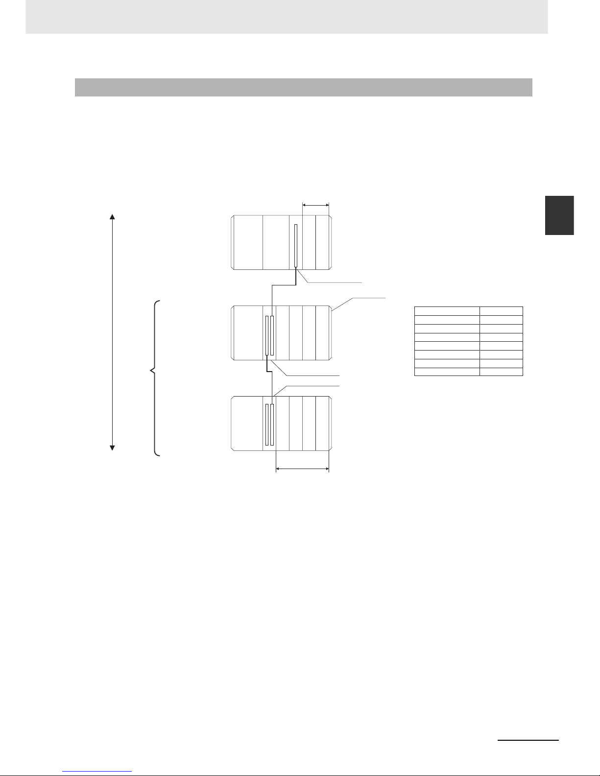
2-7
2 Basic System Configuration and Devices
CJ2 CPU Unit Hardware User’s Manual
2-1 Basic System Configuration
2
2-1-3 Expansion Racks
CJ-series Expansion Racks can be connected to the CPU Rack to expand the number of Units in the
System beyond the CPU Rack. Up to 10 I/O Units can be mounted to each Expansion Rack and a total
of 3 Expansion Racks can be connected.
Mount an I/O Control Unit immediately to the right of the CPU Unit, and mount the I/O Interface Unit
immediately to the right of the Power Supply Unit on the Expansion Rack. Mounting them in other locations may cause malfunctions.
2-1-3 Expansion Racks
CPU Rack
CS/CJ-series I/O Connecting Cables
Cable
CS1W-CN313
CS1W-CN713
CS1W-CN223
CS1W-CN323
CS1W-CN523
CS1W-CN133
CS1W-CN133B2
Length
0.3 m
0.7 m
2 m
3 m
5 m
10 m
12 m
CJ-series
Expansion Rack
CS/CJ-series I/O Connecting Cable
30 cm, 70 cm, 2 m, 3 m, 5 m, 10 m, 12 m
Expansion
Racks:
3 maximum
Total cable
length:
12 m
End Cover
I/O Control Unit
*3
I/O Interface Unit
I/O Interface Unit
10 Units max.
Powe r
Supply
Unit
Powe r
Supply
Unit
Powe r
Supply
Unit
CJ-series
Expansion Rack
CS/CJ-series I/O Connecting Cable
30 cm, 70 cm, 2 m, 3 m, 5 m, 10 m, 12 m
CPU
Unit
10 Units max.
Page 62

2 Basic System Configuration and Devices
2-8
CJ2 CPU Unit Hardware User’s Manual
z Units for CJ-series Expansion Racks
z CJ-series Power Supply Unit
z I/O Interface Unit
*1 Includes the weight of the End Cover.
Maximum Number of Expansion Racks
Expansion pattern Maximum number of Racks Remarks
CJ-series CPU Rack plus
CJ-series Expansion Racks
3 Racks The total length of I/O Connecting Cable
between the CPU Rack and an Expansion Rack,
and between all Expansion Racks, must be no
more than 12 m.
Units
Rack Configuration Remarks
CJ-series
Expansion
Racks
CJ-series Power Supply Unit One required for each Expansion Rack. (An I/O Control
Unit is required on the CJ-series CPU Rack.)
I/O Interface Unit (one End Cover
included.)
CJ-series Basic I/O Units A total of up to 10 Units can be connected to the CPU
Rack and to each of the Expansion Racks. (An error will
occur if 11 or more Units are connected.)
CJ-series Special I/O Units
CJ-series CPU Bus Units
End Cover Must be connected to the right end of the Expansion
Rack. (One End Cover is provided with the I/O Interface
Unit. A fatal error will occur if the End Cover is not connected.)
CS/CJ-series I/O Connecting Cable Required to connect the I/O Interface Unit to the I/O
Control Unit or previous I/O Interface Unit.
Model
Power supply
voltage
Output capacity
Functions
5 VDC 24 VDC
CJ1W-PA205R 100 to 240 VAC 5.0 A 0.8 A RUN output
Replacement notification
CJ1W-PA205C 100 to 240 VAC 4.6 A 0.8 A
CJ1W-PA202 100 to 240 VAC 2.8 A 0.4 A
CJ1W-PD025 24 VDC 5.0 A 0.8 A
CJ1W-PD022 24 VDC
(non-insulated type)
2.0 A 0.4 A
Model Specifications
Current consump-
tion (A)
Weight
5 VDC 24 VDC
CJ1W-II101 One Interface Unit is required for each CJ-series Expan-
sion Rack. One End Cover is provided with each Unit.
0.13 A --- 130 g
max.
*1
Page 63

2-9
2 Basic System Configuration and Devices
CJ2 CPU Unit Hardware User’s Manual
2-1 Basic System Configuration
2
2-1-3 Expansion Racks
z End Cover
z CS/CJ-series I/O Connecting Cables
Model Specifications
Current con-
sumption (A)
Weight
CJ1W-TER01 Must be connected to the right end of the CPU Rack. (A
fatal error will occur if the End Cover is not connected to
the right end of the Rack.)
One End Cover is provided with the CPU Unit and with an
I/O Interface Unit.
Included with the
CPU Unit or
I/O Interface Unit.
---
Model Specifications Cable length
CS1W-CN313 An I/O Connecting Cable connects an I/O Control Unit (CJ1W-IC101) to an
I/O Interface Unit (CJ1W-II101), or connects an I/O Interface Unit to
another I/O Interface Unit.
0.3 m
CS1W-CN713 0.7 m
CS1W-CN223 2 m
CS1W-CN323 3 m
CS1W-CN523 5 m
CS1W-CN133 10 m
CS1W-CN133B2 12 m
Page 64

2 Basic System Configuration and Devices
2-10
CJ2 CPU Unit Hardware User’s Manual
A maximum of 10 Units can be connected to the CPU Rack for a CJ2 CPU Unit or to an Expansion
Rack. There are no restrictions in the number of each model of Unit based on location.
Note A fatal error will occur and the CPU Unit will not operate if more than the allowable number of Units is con-
nected to a CJ2 CPU Rack or to an Expansion Rack.
The Configuration Units with which the CJ2 CPU Unit can exchange data are classified into three
groups. The number of Units that can be mounted depends on the type of Unit.
2-1-4 Configuration Units
Maximum Number of Units
Models of Configuration Units
Units Description
Unit identifica-
tion method
Number of
mountable Units
Basic I/O Units Basic I/O Units are used for discrete inputs and
outputs.
Identified by the
CPU Unit according to mounting
position.
No limit
Special I/O Units Special I/O Units are more advanced than Basic
I/O Units. They support functions other than discrete inputs and outputs.
Examples:
Analog I/O Units and High-speed Counter Units
Special I/O Units have a smaller area for
exchanging data with the CPU Unit than CPU
Bus Units (including Network Communications
Units).
Identified by the
CPU Unit using
unit numbers 0 to
95 set with the
rotary switches on
the front panel of
the Unit.
Up to 96 Special
I/O Units can be
mounted.
(Depending on the
model, 1 to 4 unit
numbers are used
for one Unit.)
CPU Bus Unit CPU Units are advanced units that exchange
data with the CPU Unit via the CPU bus.
Examples:
Network Communications Units and Serial Communications Units
CPU Bus Units have a larger area for exchanging data with the CPU Unit than Special I/O
Units.
Identified by the
CPU Unit using
unit number 0 to F
set with the rotary
switch on the front
panel of the Unit.
Up to 15 CPU Bus
Units can be
mounted.
Page 65

2-11
2 Basic System Configuration and Devices
CJ2 CPU Unit Hardware User’s Manual
2-1 Basic System Configuration
2
2-1-4 Configuration Units
z CJ-series Basic I/O Units
Input Units
*1 The cable-side connector is not provided with Units equipped with cables. Purchase the cable separately
(Refer to 5-3-3 Wiring Basic I/O Units with Connectors.), or use an OMRON Connector- Terminal Block Conversion Unit or I/O Terminal (Refer to 5-3-4 Connecting to Connector-Terminal Block Conversion Units or I/O
Relay Terminals.).
*2 Although 16 I/O bits are allocated, only 8 of these can be used for external I/O. This Unit is also treated as a
16-point I/O Unit in the I/O tables.
*3 An Interrupt Input Unit can be connected only in a CJ-series CPU Rack. When using the CJ2H-CPU@@-EIP,
connect the Interrupt Input Units in slots 0 to 3 in the CPU Rack. An I/O setting error will occur if the Unit is connected in other positions in the CPU Rack or to any position in an Expansion Rack. Up to two Interrupt Input
Units can be connected.
Configuration Units
Name Specifications Model
Number of
bits allo-
cated
Current consumption
(A)
Weight
5 VDC 24 VDC
DC Input
Units
Terminal block
12 to 24 VDC, 8 inputs
CJ1W-ID201
16
*2
0.08 --- 110 g max.
Terminal block
24 VDC, 16 inputs
CJ1W-ID211 16 0.08 --- 110 g max.
Fujitsu-compatible connector
24 VDC, 32 inputs
CJ1W-ID231
*1
32 0.09 --- 70 g max.
MIL connector
24 VDC, 32 inputs
CJ1W-ID232
*1
32 0.09 --- 70 g max.
Fujitsu-compatible connector
24 VDC, 64 inputs
CJ1W-ID261
*1
64 0.09 --- 110 g max.
MIL connector
24 VDC, 64 inputs
CJ1W-ID262
*1
64 0.09 --- 110 g max.
AC Input
Units
200 to 240 VAC,
8 inputs
CJ1W-IA201
16
*2
0.08 --- 130 g max.
100 to 120 VAC,
16 inputs
CJ1W-IA111 16 0.09 --- 130 g max.
Interrupt Input
Units
24 VDC, 16 inputs
CJ1W-INT01
*3
16 0.08 --- 110 g max.
Quickresponse
Input Units
24 VDC, 16 inputs CJ1W-IDP01 16 0.08 --- 110 g max.
B7A Interface
Units
64 inputs CJ1W-B7A14 64 0.09 --- 80 g max.
Page 66

2 Basic System Configuration and Devices
2-12
CJ2 CPU Unit Hardware User’s Manual
Output Units
*1 The cable-side connector is not provided with Units equipped with cables. Purchase the cable separately
(Refer to 5-3-3 Wiring Basic I/O Units with Connectors.), or use an OMRON Connector- Terminal Block Conversion Unit or I/O Terminal (Refer to 5-3-4 Connecting to Connector-Terminal Block Conversion Units or I/O
Relay Terminals.).
*2 Although 16 I/O bits are allocated, only 8 of these can be used for external I/O. This Unit is also treated as a
16-point I/O Unit in the I/O tables.
Name Specifications Model
Number of
bits allo-
cated
Current consumption
(A)
Weight
5 VDC 24 VDC
Relay Output Units Terminal block, 250 VAC/24
VDC, 2 A; 8 points, independent contacts
CJ1W-OC201
16
*2
0.09 0.048
(0.006
× Num-
ber of ON outputs)
140 g max.
Terminal block, 250 VAC/24
VDC, 2 A; 16 points
CJ1W-OC211 16 0.11 0.096
(0.006
× Num-
ber of ON outputs)
170 g max.
Triac Output Unit Terminal block, 250 VAC, 0.6
A; 8 points
CJ1W-OA201
16
*2
0.22 --- 150 g max.
Transistor Output Units
Sinking
outputs
Terminal block, 12 to 24 VDC,
2 A;
8 outputs
CJ1W-OD201
16
*2
0.09 --- 110 g max.
Terminal block, 12 to 24 VDC,
0.5 A;
8 outputs
CJ1W-OD203
16
*2
0.10 --- 110 g max.
Terminal block, 12 to 24 VDC,
0.5 A;
16 outputs
CJ1W-OD211 16 0.10 --- 110 g max.
Fujitsu-compatible connector, 12 to 24 VDC, 0.5 A;
32 outputs
CJ1W-OD231
*1
32 0.14 --- 70 g max.
MIL connector, 12 to 24 VDC,
0.3 A; 32 outputs
CJ1W-OD233
*1
32 0.14 --- 70 g max.
Fujitsu-compatible connector, 12 to 24 VDC, 0.3 A;
64 outputs
CJ1W-OD261
*1
64 0.17 --- 110 g max.
MIL connector, 12 to 24 VDC,
0.3 A;
64 outputs
CJ1W-OD263
*1
64 0.17 --- 110 g max.
Sourcing outputs
Terminal block, 24 VDC, 2 A;
8 outputs, load short-circuit
protection and disconnected
line detection
CJ1W-OD202
16
*2
0.11 --- 120 g max.
Terminal block, 24 VDC, 0.5
A; 8 outputs, load short-circuit protection
CJ1W-OD204
16
*2
0.10 --- 120 g max.
Terminal block, 24 VDC, 0.5
A; 16 outputs, load short-circuit protection
CJ1W-OD212 16 0.10 --- 120 g max.
MIL connector, 24 VDC, 0.5
A; 32 outputs, load short-circuit protection
CJ1W-OD232
*1
32 0.15 --- 80 g max.
MIL connector, 12 to 24 VDC,
0.3 A;
64 outputs
CJ1W-OD262
*1
64 0.17 --- 110 g max.
B7A Interface Units 64 outputs CJ1W-B7A04 64 0.07 --- 80 g max.
Page 67

2-13
2 Basic System Configuration and Devices
CJ2 CPU Unit Hardware User’s Manual
2-1 Basic System Configuration
2
2-1-4 Configuration Units
Mixed I/O Units
*1 The cable-side connector is not provided with Units equipped with cables. Purchase the cable separately
(Refer to 5-3-3 Wiring Basic I/O Units with Connectors.), or use an OMRON Connector- Terminal Block Conversion Unit or I/O Terminal (Refer to 5-3-4 Connecting to Connector-Terminal Block Conversion Units or I/O
Relay Terminals.).
Name Specifications Model
Number of
bits allo-
cated
Current consump-
tion (A)
Weight
5 VDC 24 VDC
24-VDC
Input/
Transistor Output Units
Sinking Fujitsu-compatible
connector
Inputs:
24 VDC, 16 inputs
Outputs: 12 to
24 VDC, 0.5 A;
16 outputs
CJ1W-MD231
*1
32 0.13 --- 90 g max.
Fujitsu-compatible
connector
Inputs:
24 VDC, 32 inputs
Outputs: 12 to
24 VDC, 0.3 A;
32 outputs
CJ1W-MD261
*1
64 0.14 --- 110 g max.
MIL connector
Inputs: 24 VDC,
16 inputs
Outputs: 12 to
24 VDC, 0.5 A;
16 outputs
CJ1W-MD233
*1
32 0.13 --- 90 g max.
MIL connector
Inputs: 24 VDC,
32 inputs
Outputs: 12 to
24 VDC, 0.3 A;
32 outputs
CJ1W-MD263
*1
64 0.14 --- 110 g max.
Sourcing MIL connector
Inputs: 24 VDC,
16 inputs
Outputs: 24 VDC, 0.5
A; 16 outputs
Load-short circuit
protection
CJ1W-MD232
*1
32 0.13 --- 80 g max.
TTL I/O Units MIL connector
Inputs: TTL (5 VDC),
32 inputs
Outputs: TTL
(5 VDC, 35 mA),
32 outputs
CJ1W-MD563
*1
64 0.19 --- 110 g max.
B7A Interface Units 32 inputs, 32 outputs CJ1W-B7A22 64 0.07 --- 80 g max.
Page 68

2 Basic System Configuration and Devices
2-14
CJ2 CPU Unit Hardware User’s Manual
z CJ-series Special I/O Units
Typ e Name Specifications Model
Number of
words allocated (CIO
2000 to CIO
2959)
Number of
words allo-
cated
(D20000 to
D29599)
Unit No.
Current consump-
tion (A)
Weight
5 VDC 24 VDC
Special I/O
Units
General-purpose Universal Analog
Input Unit
4 inputs, fully universal
CJ1W-AD04U 10 words 100 words 0 to 95 0.32 --- 150 g max.
Analog Input
Units
8 inputs (4 to 20 mA,
1 to 5 V, etc.)
CJ1W-AD081-V1 10 words 100 words 0 to 95 0.42 --- 140 g max.
4 inputs (4 to 20 mA,
1 to 5 V, etc.)
CJ1W-AD041-V1 10 words 100 words 0 to 95 0.42 --- 140 g max.
Analog Output Units
4 outputs (1 to 5 V,
4 to 20 mA, etc.)
CJ1W-DA041 10 words 100 words 0 to 95 0.12 --- 150 g max.
2 outputs (1 to 5 V,
4 to 20 mA, etc.)
CJ1W-DA021 10 words 100 words 0 to 95 0.12 --- 150 g max.
8 outputs (1 to 5 V,
0 to 10 V, etc.)
CJ1W-DA08V 10 words 100 words 0 to 95 0.14 --- 150 g max.
8 outputs (4 to
20 mA)
CJ1W-DA08C 10 words 100 words 0 to 95 0.14 --- 150 g max.
Analog I/O
Unit
4 inputs (1 to 5 V, 4 to
20 mA, etc.)
4 outputs (1 to 5 V,
4 to 20 mA, etc.)
CJ1W-MAD42 10 words 100 words 0 to 95 0.58 --- 150 g max.
Isolated-type
High-resolution Universal Input Unit
4 inputs, fully universal Resolution:
1/256,000, 1/64,000,
1/16,000
CJ1W-PH41U 10 words 100 words 0 to 95 0.30 --- 150 g max.
Isolated-type
Thermocouple Input
Units
4 thermocouple
inputs
CJ1W-PTS51 10 words 100 words 0 to 95 0.25 --- 150 g max.
2 thermocouple
inputs
CJ1W-PTS15 10 words 100 words 0 to 95 0.18 --- 150 g max.
Isolated-type
Resistance
Thermometer Input
Units
4 resistance thermometer inputs
CJ1W-PTS52 10 words 100 words 0 to 95 0.25 --- 150 g max.
2 resistance thermometer inputs
CJ1W-PTS16 10 words 100 words 0 to 95 0.18 --- 150 g max.
Direct Current Input
Unit
DC voltage or DC
current, 2 inputs
CJ1W-PDC15 10 words 100 words 0 to 95 0.18 --- 150 g max.
Temperature
Control Units
4 control loops, thermocouple inputs,
NPN outputs
CJ1W-TC001 20 words 200 words 0 to 94
(uses
words for
2 unit
numbers)
0.25 --- 150 g max.
4 control loops, thermocouple inputs,
PNP outputs
CJ1W-TC002 20 words 200 words 0 to 94
(uses
words for
2 unit
numbers)
0.25 --- 150 g max.
2 control loops, thermocouple inputs,
NPN outputs, heater
burnout detection
CJ1W-TC003 20 words 200 words 0 to 94
(uses
words for
2 unit
numbers)
0.25 --- 150 g max.
2 control loops, thermocouple inputs,
PNP outputs, heater
burnout detection
CJ1W-TC004 20 words 200 words 0 to 94
(uses
words for
2 unit
numbers)
0.25 --- 150 g max.
4 control loops, temperature- resistance
thermometer inputs,
NPN outputs
CJ1W-TC101 20 words 200 words 0 to 94
(uses
words for
2 unit
numbers)
0.25 --- 150 g max.
Page 69

2-15
2 Basic System Configuration and Devices
CJ2 CPU Unit Hardware User’s Manual
2-1 Basic System Configuration
2
2-1-4 Configuration Units
Special I/O
Units
Temperature
Control Units
4 control loops, temperature- resistance
thermometer inputs,
PNP outputs
CJ1W-TC102 20 words 200 words 0 to 94
(uses
words for
2 unit
numbers)
0.25 --- 150 g max.
2 control loops, temperature-resistance
thermometer inputs,
NPN outputs, heater
burnout detection
CJ1W-TC103 20 words 200 words 0 to 94
(uses
words for
2 unit
numbers)
0.25 --- 150 g max.
2 control loops, temperature-resistance
thermometer inputs,
PNP outputs, heater
burnout detection
CJ1W-TC104 20 words 200 words 0 to 94
(uses
words for
2 unit
numbers)
0.25 --- 150 g max.
Posi ti on Control Units
1 axis, pulse output;
open collector output
CJ1W-NC113 10 words 100 words 0 to 95 0.25 --- 100 g max.
2 axes, pulse outputs; open collector
outputs
CJ1W-NC213 10 words 100 words 0 to 95 0.25 --- 100 g max.
4 axes, pulse outputs; open collector
outputs
CJ1W-NC413 20 words 200 words 0 to 94
(uses
words for
2 unit
numbers)
0.36 --- 150 g max.
1 axis, pulse output;
line driver output
CJ1W-NC133 10 words 100 words 0 to 95 0.25 --- 100 g max.
2 axes, pulse outputs; line driver outputs
CJ1W-NC233 10 words 100 words 0 to 95 0.25 --- 100 g max.
4 axes, pulse outputs; line driver outputs
CJ1W-NC433 20 words 200 words 0 to 94
(uses
words for
2 unit
numbers)
0.36 --- 150 g max.
Space Unit
*1
CJ1W-SP001 None None --- 0.56 --- 50 g max.
ID Sensor
Units
V600-series singlehead type
CJ1W-V600C11 10 words 100 words 0 to 95 0.26 0.12 120 g max.
V600-series twohead type
CJ1W-V600C12 20 words 200 words 0 to 94
(uses
words for
2 unit
numbers)
0.32 0.24 130 g max.
V680-series singlehead type
CJ1W-V680C11 10 words 100 words 0 to 95 0.26 0.13 120 g max.
V680-series twohead type
CJ1W-V680C12 20 words 200 words 0 to 94 0.32 0.26 130 g max.
High-speed
Counter Unit
Two-axis pulse input,
counting rate:
500 kcps max.,
line driver compatible
CJ1W-CT021 40 words 400 words 0 to 92
(uses
words for
4 unit
numbers)
0.28 --- 100 g max.
CompoNet
Master Unit
CompoNet remote
I/O: 2,048 words, 512
bits max.
CJ1W-CRM21 10 words 100 words 0 to 95 0.40 --- 130 g max.
CompoBus/S Master Units
CompoBus/S remote
I/O, 256 bits max.
CJ1W-SRM21 10 words or
20 words
None 0 to 95 or
0 to 94
0.15 ---
66 g max.
*2
Type Name Specifications Model
Number of
words allo-
cated (CIO
2000 to CIO
2959)
Number of
words allo-
cated
(D20000 to
D29599)
Unit No.
Current consump-
tion (A)
Weight
5 VDC 24 VDC
Page 70

2 Basic System Configuration and Devices
2-16
CJ2 CPU Unit Hardware User’s Manual
*1 The Space Unit is for Position Control Units.
*2 Includes the weight of accessory connectors.
Special I/O
Units
CompoNet
Master Unit
CompoNet remote
I/O
CJ1W-CRM21 130 g max.
Communications
mode No. 0: 128
inputs/128 outputs for Word
Slaves
20 words None 0 to 94
(uses
words for
2 unit
numbers)
0.40 ---
Communications
mode No. 1: 256
inputs/256 outputs for Word
Slaves
40 words None 0 to 92
(uses
words for
4 unit
numbers)
0.40 ---
Communications
mode No. 2: 512
inputs/512 outputs for Word
Slaves
80 words None 0 to 88
(uses
words for
8 unit
numbers)
0.40 ---
Communications
mode No. 3: 256
inputs/256 outputs for Word
Slaves and 128
inputs/128 outputs for Bit
Slaves
80 words None 0 to 88
(uses
words for
8 unit
numbers)
0.40 ---
Communications
mode No. 8:
1,024 inputs/
1,024 outputs for
Word Slaves and
256 inputs/256
outputs for Bit
Slaves maximum
10 words Depends on
setting
0 to 95
uses
words for
1 unit
number)
0.40 ---
Typ e Name Specifications Model
Number of
words allocated (CIO
2000 to CIO
2959)
Number of
words allo-
cated
(D20000 to
D29599)
Unit No.
Current consump-
tion (A)
Weight
5 VDC 24 VDC
Page 71

2-17
2 Basic System Configuration and Devices
CJ2 CPU Unit Hardware User’s Manual
2-1 Basic System Configuration
2
2-1-4 Configuration Units
z CJ-series CPU Bus Units
*1 Slave I/O are allocated in DeviceNet Area (CIO 3200 to CIO 3799).
*2 Some CJ-series CPU Bus Units are allocated words in the CPU Bus Unit Setting Area. The system must be designed so
that the number of words allocated in the CPU Bus Unit Setting Area does not exceed its capacity. Refer to 4-6-2 Proce-
dure for Setting CPU Bus Unit Setup Area in the CJ2 CPU Unit Software User’s Manual (Cat. No. W473).
*3 Increases by 0.15 A/Unit when an NT-AL001 RS-232C/RS-422A Link Adapter is used. Increases by 0.04 A/Unit when a
CJ1W-CIF11 RS-422A Conversion Unit is used.
*4 When mounting to a CJ-series CPU Rack or a CJ-series Expansion Rack, one of these Units uses the space of three
Units.
*5 Includes the weight of accessory connectors.
*6 Use version 2 or higher of the SYSMAC SPU Unit with a CJ2 CPU Unit.
Typ e Name Specifications Model
Number of
words allo-
cated (CIO
1500 to CIO
1899)
Unit No.
Current consumption
(A)
Weight
5 VDC 24 VDC
CPU Bus
Units
*2
High-speed
Analog Input
Unit
4 inputs: 80 µs/2 inputs,
160 µs/4 inputs
CJ1W-ADG41 25 words 0 to F 0.65 --- 150 g max.
Controller Link
Units
Wired data links CJ1W-CLK23 25 words 0 to F 0.35 --- 110 g max.
Serial Communications Units
One RS-232C port and
one RS-422A/485 port
CJ1W-SCU41-V1 25 words 0 to F
0.38
*3
--- 110 g max.
Two RS-232C ports CJ1W-SCU21-V1
0.28
*3
Two RS-422A/485 ports CJ1W-SCU31-V1 0.38
Ethernet Units 100Base-TX, FINS
communications, socket
service, FTP server,
and mail communications
CJ1W-ETN21 25 words 0 to F
(4 Units
max.)
0.38 --- 110 g max.
CPU Bus
Units
*2
EtherNet/IP
Unit
Tag data links, FINS
communications, CIP
message communications, FTP server, etc.
CJ1W-EIP21 25 words 0 to F 0.41 --- 94 g max.
FL-net Unit 100Base-TX cyclic
transmissions and message transmissions
CJ1W-FLN22 25 words 0 to F
(4 Units
max.)
0.37 --- 100 g max.
DeviceNet Unit DeviceNet remote I/O,
2,048 points; Both Master and Slave functions,
Automatic allocation
possible without Configurator
CJ1W-DRM21
25 words
*1
0 to F 0.29 ---
118 g max.
*5
Position Control Units supporting
MECHATROLINK-II
communications
MECHATROLINK-II,
16 axes max.
CJ1W-NCF71 25 words 0 to F 0.36 --- 95 g max.
Motion Control
Units supporting MECHATROLINK-II
communica-
tions
*4
MECHATROLINK-II,
Real axes: 30 max.,
Virtual axes: 2 max.,
Special motion control
language
CJ1W-MCH71 25 words 0 to F 0.60 0.80 210 g max.
SYSMAC SPU
Unit (Highspeed Storage
and Processing Unit)
One CF card type I/II
slot (used with OMRON
HMC-EF@@@ Memory
Card), one Ethernet
port
CJ1W-SPU01V2
*6
Not used. 0 to F 0.56 --- 180 g max.
Page 72
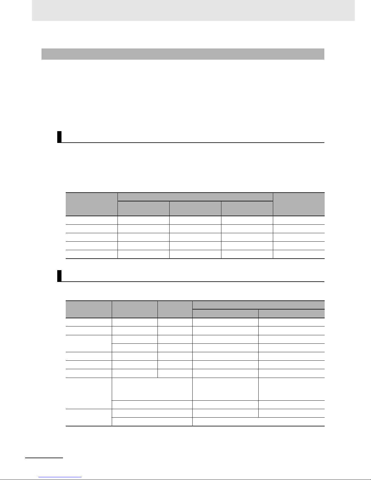
2 Basic System Configuration and Devices
2-18
CJ2 CPU Unit Hardware User’s Manual
The amount of current/power that can be supplied to the Units mounted in a Rack is limited by the
capacity of the Rack’s Power Supply Unit. Refer to the following tables when designing your system so
that the total current consumption of the mounted Units does not exceed the maximum current for each
voltage group and the total power consumption does not exceed the maximum for the Power Supply
Unit.
For details on calculating the current consumption of Units, refer to 2-1-2 CPU Rack, 2-1-3 Expansion
Racks, and 2-1-4 Configuration Units.
The following table shows the maximum currents and power that can be supplied by Power Supply
Units in CPU Racks and Expansion Racks.
Note 1 When calculating current/power consumption in a CPU Rack, be sure to include the power required by the
CPU Unit itself, as well as the I/O Control Unit if one or more Expansion Racks is connected.
2 Be sure to include the power required by the I/O Interface Unit when calculating current/power consump-
tion in an Expansion Rack.
Example 1: In this example, the following Units are mounted to a CPU Rack with a CJ1WPA205R
Power Supply Unit.
2-1-5 Calculating Unit Current Consumption
Maximum Current and Power Supplied by Power Supply Units
Power Supply Unit
Max. current consumption
Max. total power
consumption
5-V group
(internal logic)
24-V group
(relays)
24-V group
(service)
CJ1W-PA205R 5.0 A 0.8 A None 25 W
CJ1W-PA205C 5.0 A 0.8 A None 25 W
CJ1W-PA202 2.8 A 0.4 A None 14 W
CJ1W-PD025 5.0 A 0.8 A None 25 W
CJ1W-PD022 2.0 A 0.4 A None 19.6 W
Example Calculations
Unit Model Quantity
Voltag e g ro u p
5-V 24-V
CPU Unit CJ2H-CPU68-EIP 1 0.820 A ---
I/O Control Unit CJ1W-IC101 1 0.020 A ---
Input Units CJ1W-ID211 2 0.080 A ---
CJ1W-ID231 2 0.090 A ---
Output Unit CJ1W-OC201 2 0.090 A 0.048 A
Special I/O Unit CJ1W-DA041 1 0.120 A ---
CPU Bus Unit CJ1W-CLK23 1 0.350 A ---
Current consumption
Calculation 0.820 A + 0.020 + 0.080 ×
2 + 0.090 × 2 + 0.090 × 2 +
0.120 + 0.350
0.048 × 2
Result 1.83 A (≤5.0 A) 0.096 A (≤0.8 A)
Power consumption
Calculation 2.51 × 5 V = 9.15 W 0.096 A × 24 V = 2.304 W
Result 9.15 + 2.30 = 11.45 W (≤25 W)
Page 73

2-19
2 Basic System Configuration and Devices
CJ2 CPU Unit Hardware User’s Manual
2-1 Basic System Configuration
2
2-1-5 Calculating Unit Current Consumption
Example 2: In this example, the following Units are mounted to a CJ-series Expansion Rack with a
CJ1W-PA205R Power Supply Unit.
Additional Information
Rack Current Consumption and Width Display
To display the current consumption and width of Units connected in the CPU Rack or Expansion
Rack, select Current Consumption and Width from the Options Menu in the CJ2 CPU Unit I/O
Tab l e Wi nd ow.
If the capacity of a Power Supply Unit is exceeded, it will be displayed in red.
Unit Model Quantity
Voltage group
5-V 24-V
I/O Interface Unit CJ1W-II101 1 0.130 A ---
Input Unit CJ1W-ID211 2 0.080 A ---
Output Unit CJ1W-OD231 8 0.140 A ---
Current consumption
Calculation 0.130 + 0.080 × 2 + 0.140
× 8
---
Result 1.41 A (≤5.0 A) ---
Power consumption
Calculation 1.41 × 5 V = 7.05 W ---
Result 7.05 W (≤25 W)
Power Supply
Unit model
Current
consumption
at 5 V
Current
consumption
at 26/24 V
Total power
consumption
Indicates
long-distance
expansion
Width
Page 74

2 Basic System Configuration and Devices
2-20
CJ2 CPU Unit Hardware User’s Manual
The ambient operating temperature at the control panel for mounting a CJ-series PLC must be no
higher than 55°C. This section describes how to calculate the power consumption of a CPU Rack for
use in the thermal design of the control panel.
Use the following equation to calculate the average power consumption (W) of a CJ-series CPU Rack.
z Basic PLC Power Consumption (W_PLC)
The basic PLC power consumption is calculated based on the overall power consumption of the
PLC and the power conversion rate of the Power Supply Unit.
W_PLC = W_unit ÷ η
• W_unit:
Total power consumption of Units mounted to the CPU Rack. For details on the current consumption and voltage of individual Units, refer to ???.
• η:
Power Supply Unit power conversion rate.
The rate is 70% for the CJ Series, so use “0.7” in the calculation.
z Basic I/O Unit Power Consumption (W_IO_ONOFF)
The Basic I/O Unit power consumption is the total consumption for the Input Units and the Output
Units.
• Input Units
Rated input voltage × Input current × Number of input points
• Output Units
Residual voltage × Maximum load current × Number of output points
Note For the CJ Series, calculate the residual voltage at 0.1 V.
2-1-6 Calculating Power Consumption
Calculating Power Consumption
W = W_PLC
+ W_IO_ONOFF
Basic I/O Unit power consumption
Basic PLC power consumption
Page 75

2-21
2 Basic System Configuration and Devices
CJ2 CPU Unit Hardware User’s Manual
2-1 Basic System Configuration
2
2-1-6 Calculating Power Consumption
These examples show how to calculate the power consumption (W) for the following system.
z Basic PLC Power Consumption (W_PLC)
W_PLC = (0.82 + 0.09 × 2 + 0.17 × 2 + 0.58 × 2)A × 5 V ÷ 0.7= 17.86 W
z Basic I/O Unit Power Consumption (W_IO_ONOFF)
W_IO_ONOFF = 24 V × 0.0041 A x 128 points + 0.1 × 0.3 A × 128 points = 16.43 W
z Average Power Consumption (W)
W = W_PLC + W_IO_ONOFF = 34.29 W
Calculation Examples
Units Model Quantity 5 VDC Other
CPU Unit CJ2H-CPU68-EIP 1 Unit 0.82 A ---
Input Units CJ1W-ID261 2 Units 0.09 A Rated input voltage: 24 V
Input current: 4.1 mA
Number of input points: 64
Output Unit CJ1W-OD261 2 Units 0.17 A Residual voltage: 0.1 V
Maximum load current: 0.3 A
Number of output points: 64
Special I/O
Units
CJ1W-MAD42 2 Units 0.58 A ---
CPU Rack
Power Supply
Unit
CJ2H-CPU68-EIP
CPU Unit
CJ1W-MAD42 × 2
Special I/O Units
CJ1W-ID261 × 2
CJ1W-OD261 × 2
Basic I/O Units
Page 76

2 Basic System Configuration and Devices
2-22
CJ2 CPU Unit Hardware User’s Manual
2-2 Expanded System Configuration
This section describes the system configurations that can be connected by using the serial port that is
built into the CJ2 CPU Unit, along with Communications Units and other Configuration Units.
This expanded system can be connected via the CJ2 CPU Unit's built-in serial communications port or
a Serial Communications Unit.
Various protocols, including Host Link and NT Link, can be used with the serial communications port. A
particular protocol can be supported by switching the mode of the serial communications port.
For details on the serial communications modes that are supported, refer to the CJ2 CPU Unit Software
User’s Manual (Cat. No. W473).
Note Protocol macros are supported only for Serial Communications Units.
2-2-1 Serial Communications
P
E
RIP
HER
A
L
ER
R
/
ALM
R
U
N
INH
C
O
M
M
P
RP
H
L
CONTROLLER
P
ROGRAM
M
A
BLE
PO
R
T
OP
E
N
BUSY
MCPWR
BKUP
CPU64-EIP
CJ2H
SYSMAC
N
S
M
S
C
O
M
M
1
0
M
1
0
0M
2
ON
4
TERM
RD2
SD2
RDY
NO.
UNIT
ERH
OFF
WIRE
ERC
RUN
SCU41
RD1
TER1
SD1
PORT1
(RS422
/485)
PORT2
2
ON
4
TERM
RD2
SD2
RDY
NO.
UNIT
ERH
OFF
WIRE
ERC
RUN
SCU41
RD1
TER1
SD1
PORT1
(RS422
/485)
PORT2
2
ON
4
TERM
RD2
SD2
RDY
NO.
UNIT
ERH
OFF
WIRE
ERC
RUN
SCU41
RD1
TER1
SD1
PORT1
(RS422
/485)
PORT2
15 Serial
Communications
Units max.
CPU Unit
Serial port (RS-232C)
Communications Port 1
Communications Port 2
Page 77
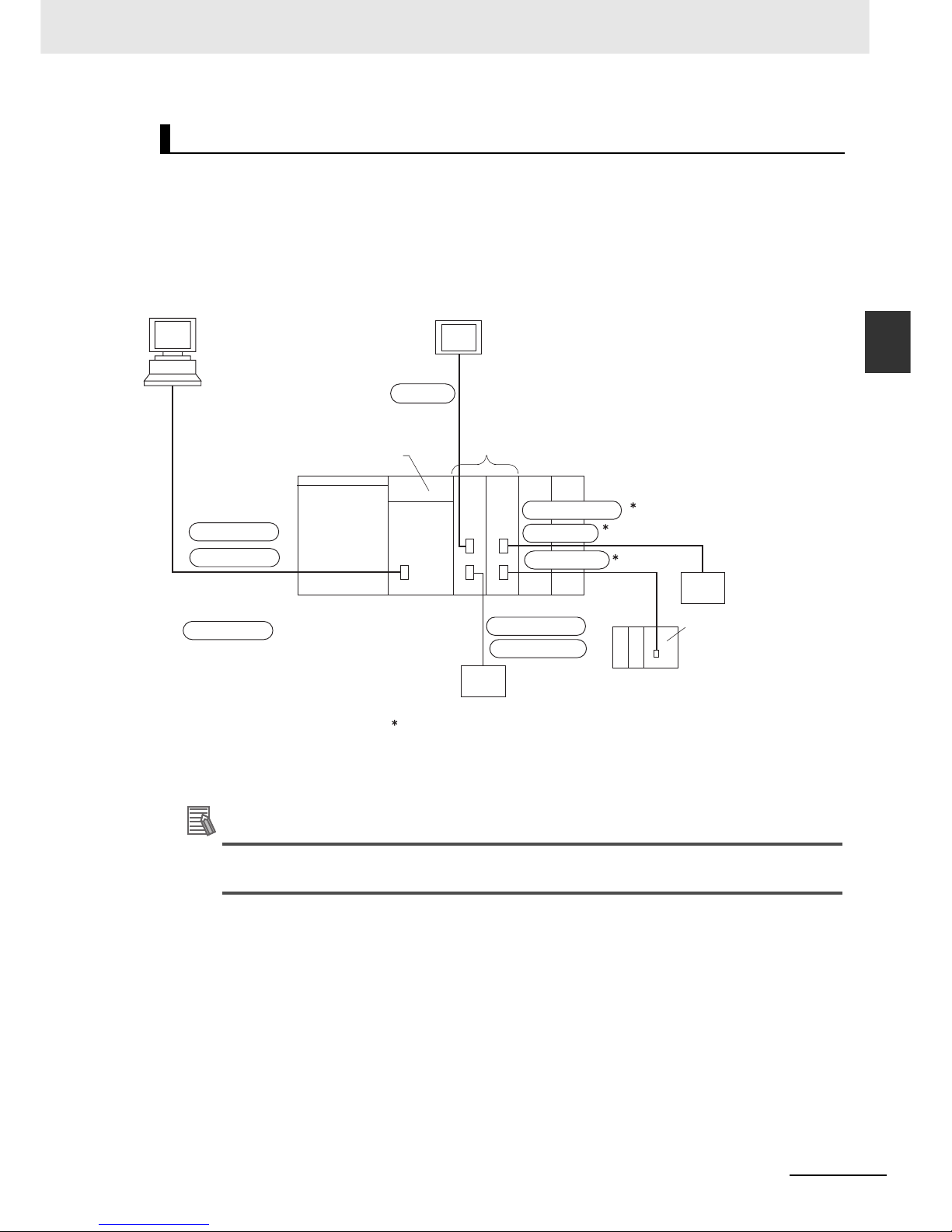
2-23
2 Basic System Configuration and Devices
CJ2 CPU Unit Hardware User’s Manual
2-2 Expanded System Configuration
2
2-2-1 Serial Communications
The host computer or a Programming Device such as the CX-Programmer is connected via the built-in
serial communications port on the CPU Unit. In addition, up to 15 Serial Communications Units can be
connected to a single CPU Unit, making it possible to configure a flexible serial communications system
by connecting devices with RS-232C or RS-422/485 ports (such as PLCs from other manufacturers,
temperature controllers, bar code readers, ID systems, personal computers, board computers, and
components).
For details on the protocol modes that can be selected for each port, refer to 11-2-1 Overview of Serial
Communications in the CJ2 CPU Unit Software User’s Manual (Cat. No. W473).
Additional Information
Use the Peripheral Bus to connect the CJ2 CPU Unit to the CX-Programmer via serial communications.
System Configuration Example
RS-232C
RS-232C
PT
CX-Programmer
or host
computer
NT Link
CPU Unit
Peripheral Bus
(Toolbus)
Host Link slave
Serial
Communications Units
CompoWay/F master
Modbus master
Host Link master
Protocol macro
No protocol
Device supporting
CompoWay/F
Device supporting
Modbus
CPU Unit
Host Link slave
General-purpose external device (e.g., such as a
PLC from other manufacturer, temperature
controller, or bar code reader)
: Protocol
This is connected using the Serial Gateway. The Serial
Gateway is supported for Serial Communications Units
with unit version 1.2 or later.
Page 78
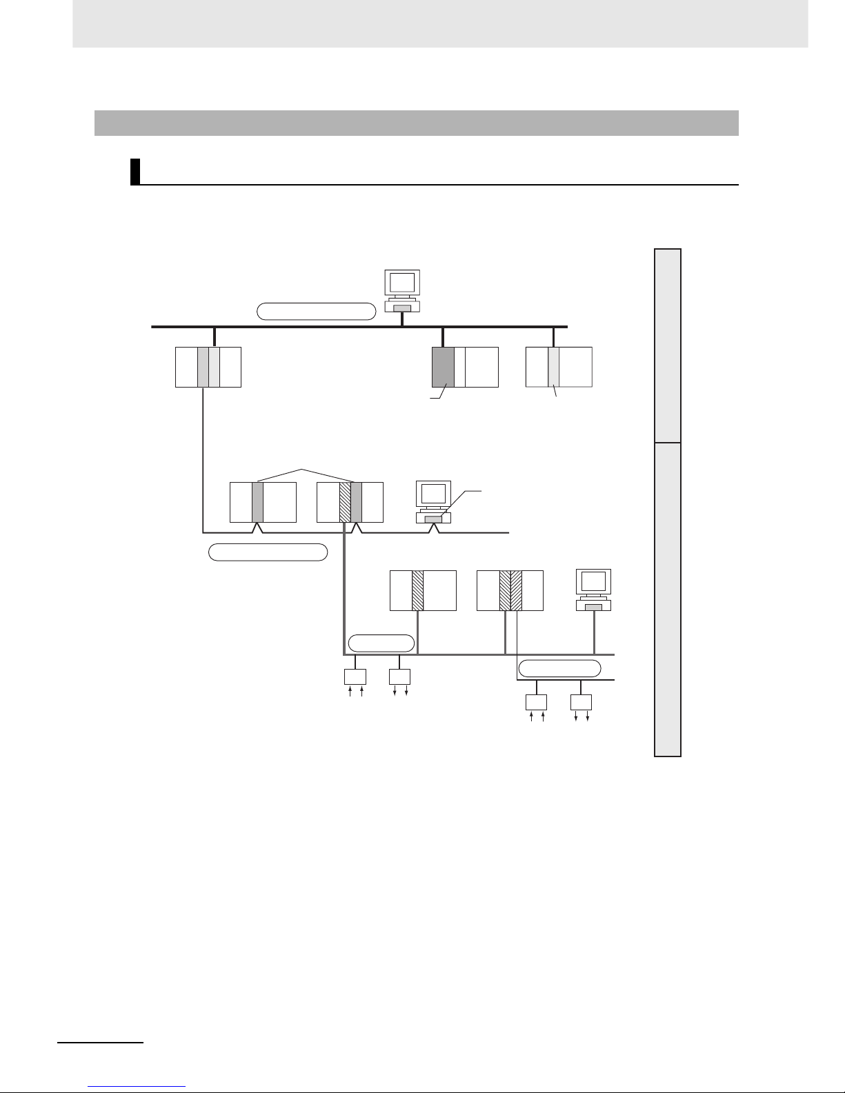
2 Basic System Configuration and Devices
2-24
CJ2 CPU Unit Hardware User’s Manual
‘
The CJ Series supports the following communications networks. Select the appropriate network
according to the applications. For details on communications networks, refer to 11-3 Communications
Networks in the CJ2 CPU Unit Software User’s Manual (Cat. No. W473).
2-2-2 Communications Networks
Communications Network Systems
DeviceNet
CompoNet
EtherNet/IP, Ethernet
Controller Link
Information network
Control network
EtherNet/IP Unit
Ethernet Unit
Connect via the built-in
EtherNet/IP port or a
EtherNet/IP Unit or Ethernet
Unit connected to the CPU Unit.
Built-in EtherNet/IP port
*1
*1: The built-in EtherNet/IP port provides the
same performance and functions as a
CJ1W-EIP21 EtherNet/IP Unit.
Controller Link Units
Controller Link
Support Board
Connect by connecting a
Controller Link Unit to the
CPU Unit. It is also possible
to communicate with a
personal computer in which
a Controller Link Support
Board is installed.
Configurator
Connect by connecting a
DeviceNet Unit to the CPU Unit.
It is also possible to connect to
various types of slaves.
Slaves
Connect by connecting a
CompoNet Unit. It is also
possible to connect to various
types of slaves.
Page 79

2-25
2 Basic System Configuration and Devices
CJ2 CPU Unit Hardware User’s Manual
2-2 Expanded System Configuration
2
2-2-2 Communications Networks
Communications Network Overview
System Network Function Communications Communications Device
Information
networks
EtherNet/IP Between Host computer and
PLC.
FINS message communications Built-in EtherNet/IP port
Between PLCs.
Between Host computer and
Memory Card installed in
CPU Unit.
FTP server
Controller Link Between PLC and personal
computer directly connected
to the Network.
FINS message communications Controller Link Support
Board or Controller Link Unit
Data link (offset, simple settings)
RS-232C → Controller Link Between Host Link computer
and PLC on the Network.
Host Link commands and gateway.
RS-232C cables and Controller Link Unit
Control
networks
EtherNet/IP Between PLCs. Tag data links Built-in EtherNet/IP port
Controller Link Between PLCs. FINS message communications Controller Link Unit
Data link (offset, simple settings)
DeviceNet FINS message communications
in an open network.
DeviceNet Master Unit and
Configurator
DeviceNet PLC and Network devices
(Slaves).
Large-capacity remote I/O (fixed
or free allocation) in an open network
DeviceNet Master Unit and
Configurator
CompoNet High-speed, multi-point, multi-
node remote I/O in an open network
CompoNet Master Unit
Page 80

2 Basic System Configuration and Devices
2-26
CJ2 CPU Unit Hardware User’s Manual
Page 81

3-1
CJ2 CPU Unit Hardware User’s Manual
3
This section gives the parts of a CJ2 PLC and describes the functions of the parts.
3-1 CPU Units . . . . . . . . . . . . . . . . . . . . . . . . . . . . . . . . . . . . . . . . . . . . . . . . . . . . 3-2
3-1-1 CPU Section . . . . . . . . . . . . . . . . . . . . . . . . . . . . . . . . . . . . . . . . . . . . . . . . . . 3-2
3-1-2 Built-in EtherNet/IP Section . . . . . . . . . . . . . . . . . . . . . . . . . . . . . . . . . . . . . . . 3-7
3-2 Memory Card . . . . . . . . . . . . . . . . . . . . . . . . . . . . . . . . . . . . . . . . . . . . . . . . 3-12
3-2-1 Models and Specifications . . . . . . . . . . . . . . . . . . . . . . . . . . . . . . . . . . . . . . . 3-12
3-2-2 Operating Procedures . . . . . . . . . . . . . . . . . . . . . . . . . . . . . . . . . . . . . . . . . . 3-12
3-2-3 Installing and Removing . . . . . . . . . . . . . . . . . . . . . . . . . . . . . . . . . . . . . . . . 3-13
3-3 Power Supply Units . . . . . . . . . . . . . . . . . . . . . . . . . . . . . . . . . . . . . . . . . . . 3-16
3-3-1 Models and Specifications . . . . . . . . . . . . . . . . . . . . . . . . . . . . . . . . . . . . . . . 3-16
3-3-2 Components . . . . . . . . . . . . . . . . . . . . . . . . . . . . . . . . . . . . . . . . . . . . . . . . . 3-19
3-3-3 Selecting a Power Supply Unit . . . . . . . . . . . . . . . . . . . . . . . . . . . . . . . . . . . . 3-21
3-4 CJ-series Basic I/O Units . . . . . . . . . . . . . . . . . . . . . . . . . . . . . . . . . . . . . . . 3-23
3-4-1 Basic I/O Units with Terminal Blocks . . . . . . . . . . . . . . . . . . . . . . . . . . . . . . . 3-23
3-4-2 Thirty-two/Sixty-four-point Basic I/O Units with Connectors . . . . . . . . . . . . . 3-25
3-5 I/O Control Units and I/O Interface Units . . . . . . . . . . . . . . . . . . . . . . . . . . 3-26
3-5-1 Component Names . . . . . . . . . . . . . . . . . . . . . . . . . . . . . . . . . . . . . . . . . . . . 3-26
3-5-2 System Configuration . . . . . . . . . . . . . . . . . . . . . . . . . . . . . . . . . . . . . . . . . . 3-26
Nomenclature and Functions
Page 82

3 Nomenclature and Functions
3-2
CJ2 CPU Unit Hardware User’s Manual
3-1 CPU Units
3-1-1 CPU Section
Components and Functions
1. Memory Card Indicators (Refer to 3-2 Memory Card.)
Indicates the Memory Card status (access and power
supply).
2. Simple Backup/Memory Card Power Supply Switch
(Refer to 3-2 Memory Card.)
Used to back up Memory Card data or turn OFF the
power when removing the Memory Card.
3. Peripheral (USB) Port
Connected to Programming Devices, such as the CXProgrammer
4. Memory Card Connector (Refer to 3-2 Memory Card.)
Connects the Memory Card to the CPU Unit.
5. Memory Card (Refer to 3-2 Memory Card.)
All CPU Unit data can be copied to a Memory Card to
back up the data. If a Memory Card Adapter is used, the
Memory Card can be mounted in the PCMIA slot in a
personal computer.
6. Memory Card Eject Button (Refer to 3-2 Memory Card.)
Press the eject button to remove the Memory Card from
the CPU Unit.
7. Slider
Secures the CPU Unit to the next Unit.
8. LED Indicators (Refer to the next page.)
These indicators show the status of the CPU Unit:
• Normal operation
• Errors
• Output OFF status
• Communications status for the peripheral (USB) and RS-
232C ports
• Backup status between RAM and built-in flash memory
9. DIP Switch (Refer to a following page.)
Sets operations, such as user memory protection, automatic program transfer by Memory Card, serial port communications mode, and simple backup.
10. RS-232C Serial Port (Refer to A-4 Connecting to the RS-
232C Serial Port on the CPU Unit.)
Connected to Programming Devices, Host Computers,
general-purpose external devices, Programmable Terminals, and other devices.
11. Connector
Connected to the next Unit.
6. Memory Card
Eject Button
5. Memory Card
4. Memory Card
Connector
8. LED Indicators
1. Memory Card Indicators
Refer to 3-1-2 Built-in EtherNet/IP Section for information
on the built-in EtherNet/IP Section.
2. Simple Backup/Memory Card
Power Supply Switch
3. Peripheral (USB)
Port
10. RS-232C Serial Port
9. DIP Switch
7. Slider
Inside the battery compartment
11. Connector
HFI
RE
PLARE
E
R
R/ALM
R
U
N
IN
H
CO
M
M
BK
U
P
PRP
HL
NS
M
S
C
OMM
10
M
10
0M
CON
T
RO
LLE
R
CPU64-EIP
CJ2H
SYSMAC
PRO
G
RAM
MABLE
PORT
OPEN
B
U
S
Y
MC
P
WR
Page 83

3-3
3 Nomenclature and Functions
CJ2 CPU Unit Hardware User’s Manual
3-1 CPU Units
3
3-1-1 CPU Section
The CJ2 CPU Unit status can be checked with the indicators at the top of the front panel of the Unit.
The following table describes these indicators.
*1 Do not turn OFF the power supply to the PLC while this indicator is lit.
CPU Unit Status Indicators
Indicator Color Status Meaning
RUN Green ON Lights when the PLC is operating normally in MONITOR or RUN
mode. The program is being executed.
Flashing System download mode error or DIP switch settings error.
OFF PLC has stopped operating while in PROGRAM mode, or has
stopped operating due to a fatal error, or is downloading data from
the system.
ERR/ALM Red ON A fatal error (including FALS(007) instruction execution) or a hard-
ware error (watchdog timer error) was found in self-diagnosis.
The CJ2 CPU Unit will stop operating, and the outputs from all
Output Units will turn OFF.
Flashing A non-fatal error was found (including FAL(006) instruction execu-
tion) in the self-diagnosis.
The CJ2 CPU Unit will continue operating.
OFF The CJ2 CPU Unit is operating normally.
INH Yellow ON Output OFF Bit (A500.15) has been turned ON.
The outputs from all Output Units will turn OFF.
OFF Output OFF Bit (A500.15) has been turned OFF.
PRPHL Yellow Flashing The CJ2 CPU Unit is communicating (sending or receiving) via the
peripheral (USB) port.
OFF The CJ2 CPU Unit is not communicating via the peripheral (USB)
port.
COMM Yellow Flashing The CJ2 CPU Unit is communicating (sending or receiving) via the
serial port (RS-232C).
OFF The CJ2 CPU Unit is not communicating via the serial port
(RS-232C).
BKUP Yellow ON User program and parameter area data is being backed up to
flash memory in the CPU Unit or being restored from flash memory after the power supply to the PLC was turned ON.
*1
OFF Data is not being written to flash memory.
Indicators on front
of CPU Unit
7-segment display and
indicators for
EtherNet/IP port
(Refer to 3-1-2
Built-in EtherNet/IP Section.)
Page 84

3 Nomenclature and Functions
3-4
CJ2 CPU Unit Hardware User’s Manual
The status of a Memory Card mounted in the CJ2 CPU Unit can be checked with the indicators in the
middle of the front panel of the Unit. The following table describes these indicators.
Memory Card Indicators
Indicator Color Status Meaning
MCPWR Green Lit Power is being supplied to the Memory Card.
Flashing Flashes once: Simple backup read, write, or verify normal
Flashes five times: Simple backup read malfunction
Flashes continuously: Simple backup write or verify malfunction
Not lit Power is not being supplied to the Memory Card.
BUSY Yellow Flashing Memory Card is being accessed.
Not lit Memory Card is not being accessed.
DIP Switch
Pin no. Usage Setting Function Default
SW1 Used to prevent programs from being
accidently overwritten from Programming Devices (including the CX-Programmer).
ON Writing disabled for user pro-
gram memory.
*1
OFF
OFF Writing enabled for user pro-
gram memory.
SW2 Set to ON to read the program
(AUTOEXEC.OBJ file) and parameter
area (AUTOEXEC.STD file) from the
Memory Card to the CPU Unit when
power is turned ON.
*2
Used to store the programs in the
Memory Card to switch operations, or
to automatically transfer programs at
startup (Memory Card ROM opera-
tion).
*3
ON The user program is automati-
cally transferred from the Memory Card when power is turned
ON.
OFF
OFF The user program is not auto-
matically transferred from the
Memory Card when power is
turned ON.
SW3 Not used. --- --- OFF
SW4 Not used. --- --- OFF
OPEN
PERIPHERAL
BUSY
MCPWR
1
2
345
6
78
ON
Page 85
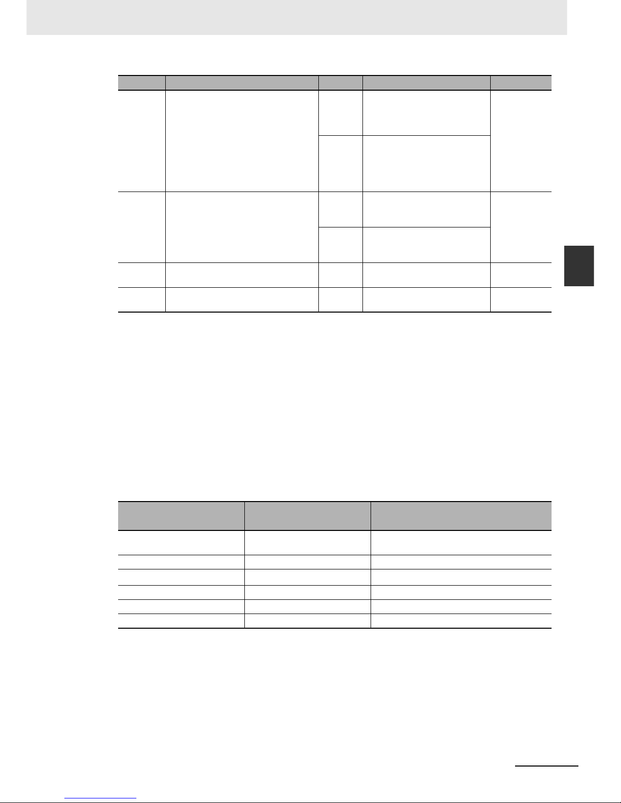
3-5
3 Nomenclature and Functions
CJ2 CPU Unit Hardware User’s Manual
3-1 CPU Units
3
3-1-1 CPU Section
*1 The following data cannot be overwritten when pin 1 is ON:
• All parts of the user program (programs in all tasks)
• All data in the parameter area (such as the PLC Setup and I/O table)
When pin 1 is ON, the user program and parameter area will not be cleared when the memory clear operation is performed from a Programming Device.
*2 I/O memory files (AUTOEXEC.IOM and ATEXEC@@@.IOM) are automatically transferred when power is
turned ON if pin 2 is set to ON. Both the program (AUTOEXEC.OBJ) and parameter area (AUTOEXEC.STD)
files must be stored on the Memory Card. It is not necessary for the I/O memory files (AUTOEXEC.IOM and
ATEXEC@@@.IOM) to be stored on the Memory Card.
*3 When pin 7 is ON, simple backup reading from the Memory Card is given priority, so even if pin 2 is ON, the
user program is not automatically transferred from the Memory Card when power is turned ON.
*4 Connecting to the PLC is not possible from the CX-One Support Software using SYSMAC WAY even if pin 5 on
the DIP switch is OFF and the PLC Setup is set to the Host Link protocol (i.e., the default setting).
*1 Set using the CX-Programmer.
*2 Connection is not possible from CX-One Support Software using the SYSMAC WAY protocol.
SW5 Set to ON to automatically detect the
baud rate of the CX-Programmer
(peripheral bus only) when using the
serial port (RS-232C).
*4
ON Serial port (RS-232C) commu-
nications condition: Automatically detect CX-Programmer
(peripheral bus only) baud rate.
OFF
OFF Serial port (RS-232C) commu-
nications condition: According
to CX-Programmer communications settings in PLC Setup.
(Refer to Tabl e 1 .)
SW6 Set pin 6 to ON or OFF and use
A395.12 in the program to create a
user-defined condition without using
an Input Unit.
ON User-defined pin. Turns ON the
User DIP Switch Pin Flag
(A395.12).
OFF
OFF User-defined pin. Turns OFF
the User DIP Switch Pin Flag
(A395.12).
SW7 Set the simple backup type. (Refer to
Table 2 below.)
--- Specifies the simple backup
type.
OFF
SW8 --- Always
OFF.
--- OFF
Table 1
Setting
Pin 5 of DIP switch on front
panel
PLC Setup (Serial port (RS-232C))
*1
Connection
1. Peripheral bus
(automatic detection)
ON ---
2. Peripheral bus OFF (default) Peripheral bus
3. Host Link
*2
OFF (default) Host Link (default)
4. NT Link OFF (default) NT Link
5. No-protocol OFF (default) No-protocol
6. Serial Gateway OFF (default) Serial Gateway
Pin no. Usage Setting Function Default
Page 86

3 Nomenclature and Functions
3-6
CJ2 CPU Unit Hardware User’s Manual
*1 This operation is given priority over automatic transfer at startup (pin 2 set to ON).
Note After reading data from the Memory Card to the CPU Unit using the simple backup operation, the CPU Unit
will remain in PROGRAM mode and no operations in any other mode will be possible. To switch to RUN or
MONITOR mode, turn OFF the power, turn OFF pin 7, turn the power back ON, and use a Programming
Device to change the operating mode.
Table 2
Simple backup type
DIP Switch
Required operation
SW7
Backing up all PLC data on the Memory Card: ON Press the Memory Card
Power Supply Switch for
3s.
Restoring all PLC data from the Memory Card: Turn ON the power to
the PLC.
*1
Comparing the Memory Card and the CPU Unit: OFF Press the Memory Card
Power Supply Switch for
3 s.
All PLC data
Memory Card
Backup
All PLC data
Memory Card
Restore
All PLC data
Memory Card
Compare
Page 87

3-7
3 Nomenclature and Functions
CJ2 CPU Unit Hardware User’s Manual
3-1 CPU Units
3
3-1-2 Built-in EtherNet/IP Section
This section describes the components related to the EtherNet/IP port section that is built into the
CJ2H-CPU@@-EIP.
Additional Information
The built-in EtherNet/IP port provides the same performance and functions as a CJ1W-EIP21
EtherNet/IP Unit. Set the unit number and node address with the rotary switches on the front
panel of the CPU Unit, and set the communications parameters with the Edit Parameters menu
command for the Special I/O Unit. For details on the Edit Parameters, refer to 8-2 Setting CPU
Bus Units and Special I/O Units in the CJ2 CPU Unit Software User’s Manual (Cat. No. W473).
For details on specifications and settings for the built-in EtherNet/IP port, refer to the CS/CJ
Series EtherNet/IP Units Operation Manual (Cat. No. W465).
With a CJ2 CPU Unit, Ethernet node status and Ethernet network status can be monitored by checking
the display and indicators at the upper right of the front of the CPU Unit.
z Status Indicators: MS, NS, COMM, 100M, and 10M
The MS (Module Status) indicator indicates the status of the built-in EtherNet/IP port itself and the
NS (Network Status) indicator indicates the status of the network.
The COMM, 100M, and 10M indicators indicate the status of Ethernet communications.
3-1-2 Built-in EtherNet/IP Section
Nomenclature and Functions
Display and Indicators for Built-in EtherNet/IP Port
Display and indicators
for built-in EtherNet/IP port
Rotary switches
Built-in EtherNet/IP port
(Refer to 5-3-5 Connecting I/O Devices.)
LA
RE
H
FI
R
E
P
N
S
M
S
COMM
10
M
1
0
0M
CO
NTROLLER
CPU64-EIP
CJ2H
SYSMAC
PRO
GRAM
M
ABLE
PORT
OPEN
BU
S
Y
MC
P
W
R
Seven-segment display and indicators
for built-in EtherNet/IP port
Page 88

3 Nomenclature and Functions
3-8
CJ2 CPU Unit Hardware User’s Manual
The MS and NS indicators can be green or red. The COMM, 100M, and 10M indicators are yellow.
These indicators can be lit, flashing, or not lit. The following table shows the meaning of these indicator conditions.
Refer to SECTION 6 Troubleshooting for details on using these indicators for troubleshooting.
z Seven-segment Display
When the power supply to the PLC is turned ON or the CPU Unit is reset, all of the segments will
flash twice, and then the IP address set for the built-in EtherNet/IP port will be displayed on the 7segment display from right to left. After the entire IP address is displayed, the lower 8 bits of the IP
address (node address) will be displayed in hexadecimal.
Indica-
tor
Name Color Status Meaning
MS Module Status Red Lit Fatal error
Flashing Recoverable error
Green Lit Normal
--- Not lit Power supply OFF
NS Network Sta-
tus
Red Lit Fatal error
Flashing Recoverable error
Green Lit Tag data link and message connections established
Flashing Tag data link and message connections not established
--- Not lit Offline or power supply OFF
COMM Communica-
tion
Yellow Lit Transferring data
Not lit Not transferring data
100 M 100 Mbps Yellow Lit 100Base-TX link established
Not lit 100Base-TX link not established
10 M 10 Mbps Yellow Lit 10Base-TX link established
Not lit 10Base-TX link not established
EIP
21
Page 89

3-9
3 Nomenclature and Functions
CJ2 CPU Unit Hardware User’s Manual
3-1 CPU Units
3
3-1-2 Built-in EtherNet/IP Section
For example, the display will change as follows if the IP address is 192.168.250.10:
If an error occurs, the error code will be displayed alternately with the rightmost byte of the affected
device’s IP address. For details on error codes, refer to 6-2-2 Checking Error Status at the Ether-
Net/IP Port Seven-segment Display.
The following examples show the displays for errors.
• A d6 error (failure to connect) has occurred in communications with IP address 192.168.250.8.
• A d6 error (failure to connect) has occurred in communications with IP address 192.168.250.9.
• A d5 error (verification error; target missing) has occurred in communications with IP address
192.168.250.40.
• A C6 error (multiple switches ON) and an EA error (EtherNet/IP expansion setting error) have
occurred at the built-in EtherNet/IP port.
: 0A
The IP address is displayed in decimal, flowing from right to left.
If the Unit is operating normally, the rightmost digits
of the Unit's IP address is displayed in hexadecimal.
Flashing: The tag data links are stopped.
Lit: The tag data links are operating.
( “0A” is the hexadecimal display
for the final row, 10, in the IP
address of the local Unit.)
: 10
: 250.
: 168.
: 192.
Example:
Example:
: Er d6 IP 08
: IP d6 IP 09
: Er d5 IP 40
: Er c6
: Er EA
: IP 0A
Information on errors that occur in
communications with the target node,
along with the last digits of the Unit’ s IP
address, are displayed in hexadecimal.
Displays errors that occurred
within the Unit.
The last digits of the
Unit’ s IP address is
displayed in hexadecimal.
Page 90
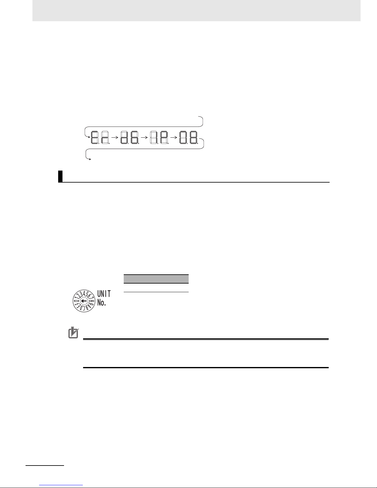
3 Nomenclature and Functions
3-10
CJ2 CPU Unit Hardware User’s Manual
• There is no priority to the order in which the errors are displayed. All of the errors are displayed
repeatedly in sequence.
Left/Right Dot LEDs
If an error occurs at multiple devices for which the rightmost 8 bits in the IP addresses are the same,
this is indicated by the dots on the right side in display on the target devices.
The following examples show the displays for multiple errors.
• d6 errors (failure to connect) have occurred in communications with IP address 10.0.1.8.
• d6 errors (failure to connect) have occurred in communications with IP address 10.0.2.8.
The unit number and node address for the CJ2 CPU Unit built-in EtherNet/IP port are set using the
rotary switches. The unit number and node address are allocated in the same way as for a CPU Bus
Unit. According to the unit number that is set, words are automatically allocated in the CIO Area and
DM Area. For details, refer to the CJ2 CPU Unit Software User’s Manual (Cat. No. W473).
z Setting the Unit Number
Set a unique unit number for the CJ2 CPU Unit built-in EtherNet/IP port. The same unit number cannot be used by any other CPU Bus Unit connected to the CJ2 CPU Unit.
Use a small screwdriver to make the setting, and be sure not to damage the rotary switch. The unit
number is factory-set to 0.
Precautions for Correct UsePrecautions for Correct Use
• Always turn OFF the PLC’s power supply before setting the unit number.
• When setting the unit number for the first time or when changing the setting, create the PLC’s
I/O tables.
z Node Address Setting Switches
Set a FINS address for the built-in EtherNet/IP port. With the FINS communications service, multiple
EtherNet/IP Units (including the CJ2 Unit built-in EtherNet/IP port) connected by Ethernet are identified by their node addresses. Using the node address switches, set a unique node address in hexadecimal. The same node address cannot be used by any other EtherNet/IP Unit or Ethernet Unit
connected on the same Ethernet network.
Rotary Switches
Setting range
0 to F
Page 91

3-11
3 Nomenclature and Functions
CJ2 CPU Unit Hardware User’s Manual
3-1 CPU Units
3
3-1-2 Built-in EtherNet/IP Section
As long as it does not duplicate any other address, the node address can be set from 01 to FE (1 to
254 in decimal).
Note The node address is factory-set to 01. With the default setting, the values set on these switches become the
last two digits of the built-in EtherNet/IP port’s IP address.
The default IP address is 192.168.250.node_address. With the factory-set node address of 01, the
default IP address is 192.168.250.1.
The node address can be set to any number in the setting range (01 to FE), as long as the same
address is not set on another node in the network.
Precautions for Correct UsePrecautions for Correct Use
• Always turn OFF the PLC’s power supply before setting the unit number.
• When setting the unit number for the first time or when changing the setting, create the PLC’s
I/O tables.
Additional Information
• If the node address setting is changed during operation, the MS Indicator will flash red.
z Relationship with IP Address
When using the automatic generation method (dynamic/static) for IP address conversion, the rightmost byte of the IP address that is set for the built-in EtherNet/IP port must be set to the same value
as the node address. If it cannot be set to the same value as the node address, then the address
conversion method must be set to the IP address table method or the IP address + automatic generation method. For details, refer to the CS/CJ Series EtherNet/IP Units Operation Manual (Cat. No.
W465).
Setting range
01 to FE hex (1 to 254 decimal)
Page 92

3 Nomenclature and Functions
3-12
CJ2 CPU Unit Hardware User’s Manual
3-2 Memory Card
Additional Information
Simple Backup
The simple backup function copies all CPU Unit data (user program, parameters, and I/O memory) to a Memory Card, without having to use a Programming Device.
For details, refer to 8-3 Simple Backup.
3-2-1 Models and Specifications
Model number HMC-EF583 HMC-EF283 HMC-EF183
Memory Card capacity 512 Mbytes 256 Mbytes 128 Mbytes
Common specifications
Dimensions 42.8 × 36.4 × 3.3 mm (W × H × T)
Weight 15 g max.
Current consumption Approx. 30 mA (when used with PLC)
Environmental specifications Same a general specifications of PLC
No. of writes 100,000 (guaranteed value)
Factory specifications
No. of files writable to root
directory
511
File system FAT1 6
3-2-2 Operating Procedures
Memory Card Eject Button
Memory Card Indicators
MCPOWER (green): Lit when power is being provided
to the Memory Card.
BUSY (orange): Lit when the Memory Card is being accessed.
Simple Backup/Memory Card Power Supply Switch
This switch has the following two functions.
•
Simple Backup
To back up all CPU Unit data to the Memory Card,
press this switch for 3 s when DIP switch pin 7 is set to ON.
•
Turning OFF Power to the Memory Card
Press this switch to turn OFF the power before removing the
Memory Card.
Page 93

3-13
3 Nomenclature and Functions
CJ2 CPU Unit Hardware User’s Manual
3-2 Memory Card
3
3-2-3 Installing and Removing
• Observe the following precautions while the Memory Card is being accessed. The Memory Card may
become unusable if these precautions are not followed.
• Never turn OFF the PLC while the CPU is accessing the Memory Card.
• Never remove the Memory Card while the CPU is accessing the Memory Card. Press the Memory
Card power supply switch and wait for the BUSY indicator to go OFF before removing the Memory
Card.
• Never insert the Memory Card facing the wrong way. If the Memory Card is inserted forcibly, it may
become unusable.
• To delete all the data on the Memory Card by formatting the Memory Card, insert the Memory Card in
the CPU Unit and perform the operation from the CX-Programmer.
1. Pull the top end of the Memory Card cover forward and remove from the Unit.
2. Insert the Memory Card with the label facing to the left. (Insert with the ∆ on the Memory Card
label and the ∆ on the CPU Unit facing each other.)
3-2-3 Installing and Removing
Before Using a Memory Card
Installing the Memory Card
Product label
Page 94

3 Nomenclature and Functions
3-14
CJ2 CPU Unit Hardware User’s Manual
3. Push the Memory Card securely into the compartment.
If the Memory Card is inserted correctly, the Memory Card eject button will be pushed out.
1. Press the Memory Card power supply switch.
2. Press the Memory Card eject button after the BUSY indicator is no longer lit.
The Memory Card will be ejected from the compartment.
3. Pull out the Memory Card.
Removing the Memory Card
Memory Card
power supply switch
Memory Card eject button
BUSY indicator
Page 95

3-15
3 Nomenclature and Functions
CJ2 CPU Unit Hardware User’s Manual
3-2 Memory Card
3
3-2-3 Installing and Removing
4. Install the Memory Card cover when a Memory Card is not being used.
Installing the Memory Card into a Personal Computer
HMC-AP001
Memory Card Adapter
Memory Card
Personal computer
PC card slot
Page 96

3 Nomenclature and Functions
3-16
CJ2 CPU Unit Hardware User’s Manual
3-3 Power Supply Units
3-3-1 Models and Specifications
Item Specifications
Power Supply Unit CJ1W-PA205R CJ1W-PA205C CJ1W-PA202 CJ1W-PD025 CJ1W-PD022
Supply voltage 100 to 240 VAC (wide-range), 50/60 Hz 24 VDC
Operating voltage
and frequency
ranges
85 to 264 VAC, 47 to 63 Hz 19.2 to 28.8 VDC 21.6 to 26.4 VDC
Power consumption 100 VA max. 50 VA max. 50 W max. 35 W max.
Inrush current
(See note 1.)
At 100 to 120 VAC:
15 A/8 ms max. for cold start at room
temperature
At 200 to 240 VAC:
30 A/8 ms max. for cold start at room
temperature
At 100 to 120
VAC :
20 A/8 ms max.
for cold start at
room temperature
At 200 to 240
VAC :
40 A/8 ms max.
for cold start at
room temperature
At 24 VDC:
30 A/20 ms max. for cold start at room
temperature
Output capacity
(See note 7.)
5.0 A, 5 VDC (including supply to CPU
Unit)
2.8 A, 5 VDC
(including supply
to CPU Unit)
5.0 A, 5 VDC
(including supply
to CPU Unit)
2.0 A, 5 VDC
(including supply
to CPU Unit)
0.8 A, 24 VDC 0.4 A, 24 VDC 0.8 A, 24 VDC 0.4 A, 24 VDC
Total: 25 W max. Total: 14 W max. Total: 25 W max. Total: 19.6 W
max.
Output terminal (service supply)
Not provided
RUN output
(See note 2.)
Contact configuration: SPST-NO
Switch capacity:
250 VAC, 2 A
(resistive load)
120 VAC, 0.5 A
(inductive load),
24 VDC, 2A
(resistive load)
24 VDC, 2 A
(inductive load)
Not provided. Not provided. Not provided. Not provided.
Replacement notification function
Not provided. With Alarm
output (open collector output)
30 VDC max.,
50 mA max.
Not provided. Not provided. Not provided.
Page 97

3-17
3 Nomenclature and Functions
CJ2 CPU Unit Hardware User’s Manual
3-3 Power Supply Units
3
3-3-1 Models and Specifications
Insulation resistance 20 MΩ min.
(at 500 VDC)
between AC
external and GR
terminals
*3
•20 MΩ min.
(at 500 VDC)
between all
external terminals and GR
terminal, and
between all
alarm output
terminals.
•20 MΩ min.
(at 250 VDC)
between all
alarm output
terminals and
GR terminal.
20 MΩ min.
(at 500 VDC)
between AC
external and GR
terminals
*3
20 MΩ min.
(at 500 VDC)
between DC
external and GR
terminals
*3
---
*6
Dielectric strength
*4
2,300 VAC 50/60
Hz for 1 min
between AC
external and GR
terminals
*3
Leakage current:
10 mA max.
•2,300 VAC,
50/60 Hz for 1
minute between
all external terminals and GR
terminal and
between all
alarm output
terminals with a
leakage current
of 10 mA max.
•1,000 VAC,
50/60 Hz for 1
minute between
all alarm output
terminals and
GR terminal
with a leakage
current of 10
mA max.
2,300 VAC 50/60
Hz for 1 min
between AC
external and GR
terminals
*3
Leakage current:
10 mA max.
1,000 VAC 50/60
Hz for 1 min
between DC
external and GR
terminals
*3
Leakage current:
10 mA max.
---
*6
1,000 VAC 50/60 Hz for 1 min between DC external and GR terminals
*3
Leakage current: 10 mA max.
Noise immunity 2 kV on power supply line (Conforms to IEC61000-4-4.)
Vibration resistance
5 to 8.4 Hz, 3.5-mm amplitude, 8.4 to 150 Hz, acceleration: 9.8 m/s
2
in X, Y, and Z directions for
100 minutes (Time coefficient: 10 minutes × coefficient factor 10 = total time 100 min.) (according to
JIS C60068-2-6)
Shock resistance
147 m/s
2
3 times each in X, Y, and Z directions (Relay Output Unit: 100 m/s2) (according to JIS
C60068-2-27)
Ambient operating
temperature
0 to 55°C
Ambient operating
humidity
10% to 90% (with
no condensation)
10% to 90% (with
no condensa-
tion)
*5
10% to 90% (with no condensation)
Atmosphere Must be free from corrosive gases.
Ambient storage temperature
−20 to 75°C
(excluding battery)
−20 to 75°C
*5
−20 to 75°C (excluding battery)
Item Specifications
Page 98

3 Nomenclature and Functions
3-18
CJ2 CPU Unit Hardware User’s Manual
*1 The AC and DC values above are given for a cold start, and the AC values are at room temperature. The AC inrush con-
trol circuit uses a thermistor element with a low-temperature current control characteristic. If the ambient temperature is
high or the PLC is hot-started, the thermistor will not be sufficiently cool, and the inrush current given in the table may be
exceeded by up to twice the given value. When selecting fuses or breakers for external circuits, allow sufficient margin in
shut-off performance. The DC inrush control circuit uses a capacitor-charging delay circuit. If the power is OFF for only a
short time for a hot-start, the capacitor will not sufficiently charge and the inrush current given in the table may be
exceeded by up to twice the given value.
*2 Supported only when mounted to CPU Rack.
*3 Disconnect the Power Supply Unit’s LG terminal from the GR terminal when testing insulation and dielectric strength.
Testing the insulation and dielectric strength with the LG terminal and the GR terminals connected will damage internal
circuits in the CPU Unit.
*4 Change the applied voltage gradually using the adjuster on the Tester. If the full dielectric strength voltage is applied or
turned OFF using the switch on the Tester, the generated impulse voltage may damage the Power Supply Unit.
*5 Maintain an ambient storage temperature of -25 to 30°C and relative humidity of 25% to 70% when storing the Unit for
longer than 3 months to keep the replacement notification function in optimum working condition.
*6 CJ1W-PD022 is not insulated between the primary DC power and secondary DC power.
*7 Internal components in the Power Supply Unit will deteriorate or be damaged if the Power Supply Unit is used for an
extended period of time exceeding the power supply output capacity or if the outputs are shorted.
Page 99

3-19
3 Nomenclature and Functions
CJ2 CPU Unit Hardware User’s Manual
3-3 Power Supply Units
3
3-3-2 Components
z Example: CJ1W-PA205R
z Example: CJ1W-PA205C
z Example: CJ1W-PA202
3-3-2 Components
POWER
PA205R
DC24V
AC240V
OUTPUT
RUN
INPUT
AC100-240V
L2/N
L1
POWER Indicator
Lit when 5 V are being output from the Power Supply Unit.
External connection terminals
RUN output
AC input
LG
GR
POWER
Yea r s
CJ1W-PA205C
TEST
NC
NC
AC100-240V
INPUT
L2/N
L1
L
+
ALARM
OUTPUT
DC30V,50mA
NORMAL:ON
ALARM :OFF
POWER Indicator
Lit when 5 V are being output
from the Power Supply Unit.
External connection
terminals
AC input
LG
GR
Alarm output
(replacement notification output)
TEST switch
The TEST switch can be used to
temporarily turn OFF the alarm output
that notifies when replacement is
needed.
Replacement notification display
POWER
PA202
INPUT
NC
NC
AC100
-240V
L2/N
L1
POWER Indicator
Lit when 5 V are being output
from the Power Supply Unit.
External connection
terminals
AC input
LG
GR
Page 100

3 Nomenclature and Functions
3-20
CJ2 CPU Unit Hardware User’s Manual
z Example: CJ1W-PD025
z Example: CJ1W-PD022
Supply 100 to 240 VAC (allowable: 85 to 264 VAC).
Note The CJ1W-PA205R, CJ1W-PA205C, and CJ1W-PA202 have a wide input range, so they do not have voltage
switching terminals.
Supply 24 VDC.
Ground to a resistance of 100 Ω or less to increase noise resistance and avoid electric shock.
AC Input
DC Input
Model
Allowable power supply voltage
fluctuation range
CJ1W-PD025 19.2 to 28.8 VDC (±20%)
CJ1W-PD022 21.6 to 26.4 VDC (±10%)
LG
POWER
PD025
DC24V+
INPUT
NC
NC
POWER Indicator
Lit when 5 V are being output from the Power Supply Unit.
External connection terminals
DC input
LG
GR
POWER
PD022
NC
NC
NC
DC24V
INPUT
+
POWER Indicator
Lit when 5 V are being output
from the Power Supply Unit.
External
connection
terminals
DC
input
NC
GR
 Loading...