

Page 1
Model
CJ1W-TS561
Thermocouple input unit
INSTRUCTION SHEET
Thank you for purchasing an OMRON product. Read this
instruction sheet thoroughly and familiarise yourself with the
functions and characteristics of the product before using it.
To ensure safe and correct use of this Unit, also read the
Operation- and Programming Manuals for your CJ1 PLC system.
Keep this instruction sheet for future reference.
OMRON MANUFACTURING OF THE NETHERLANDS B.V.
OMRON Corporation 2004 All Rights Reserved
■ General Specifications
Unit classification CJ-series Basic I/O Unit
Compatible Racks CJ-series CPU Rack or
CJ-series Expansion Rack
Max. number of
Units
10 Units/Rack max.
(This requires a CJ1G or CJ1H CPU)
CPU Unit data area
for inputs
Basic I/O area CIO0000 – 0999
(3, 4 or 6 words allocated in IO Table)
Insulation resistance
20 MΩ min. (at 500 V DC) between
input terminals and PLC I/O bus.
Dielectric Strength 500 V AC, 50/60 Hz for 1 min. (detection
current: 1 mA), between Input terminals
and PLC I/O bus.
Internal current
consumption
220 mA max., 5 V DC,
from the PLC I/O bus.
Dimensions 31 x 90 x 65 mm (W x H x D)
Weight 150 g max.
Other
Other general specifications conform to
the CJ-series general specifications.
See Operation Manual W393.
■ Characteristics
■ Unit Description
Thermocouple input K-type or J-type (IEC 60584)
Number of inputs 1 to 6
Measurement range K-type: -200.0 to +1300.0 °C
J-type: -100.0 to +850.0 °C
Indication resolution 0.1 °C
Cold junction
compensation
- Accuracy
Internal measurement of terminal
temperature, once in each scan cycle.
± 2.0 °C in a stable temperature
environment (no direct heat or airflow).
Temperature value
Data representation
16-bit signed integer in units of 0.1 °C:
#F830 = -200.0 °C, #32C8 = +1300.0 °C
Indication accuracy *
over full operational
range (0 – 55 °C
ambient temperature)
± 0.5 % of indicated value or ± 0.7 °C
(whichever is larger) ± 1 digit max.
±2.0 °C ± 1 digit max. using a K-type
thermocouple below –100 °C.
Input response time
(per active input)
40 ms (100 Hz suppression)
67 ms (60 Hz suppression)
80 ms (50 Hz suppression)
400 ms (50+60 Hz suppression)
Input update cycle
time (all active inputs)
[number of active inputs + 1] x [input
response time] + 40 ms
I/O refresh time
(influence on PLC
cycle time)
1-3 inputs (48pt mode): 0.008 ms
4 inputs (64pt mode): 0.011 ms
5-6 inputs (96pt mode): 0.016 ms
The CJ1W-TS561 is a 6-channel input unit for K-type and J-type
thermocouples. It can be installed in any CJ1-series PLC system.
It is classified as a basic I/O unit, occupying 48, 64 or 96 I/O points,
depending on the number of activated inputs.
Always verify that the maximum I/O capacity of the CJ1 CPU is
sufficient for the number of required I/O points.
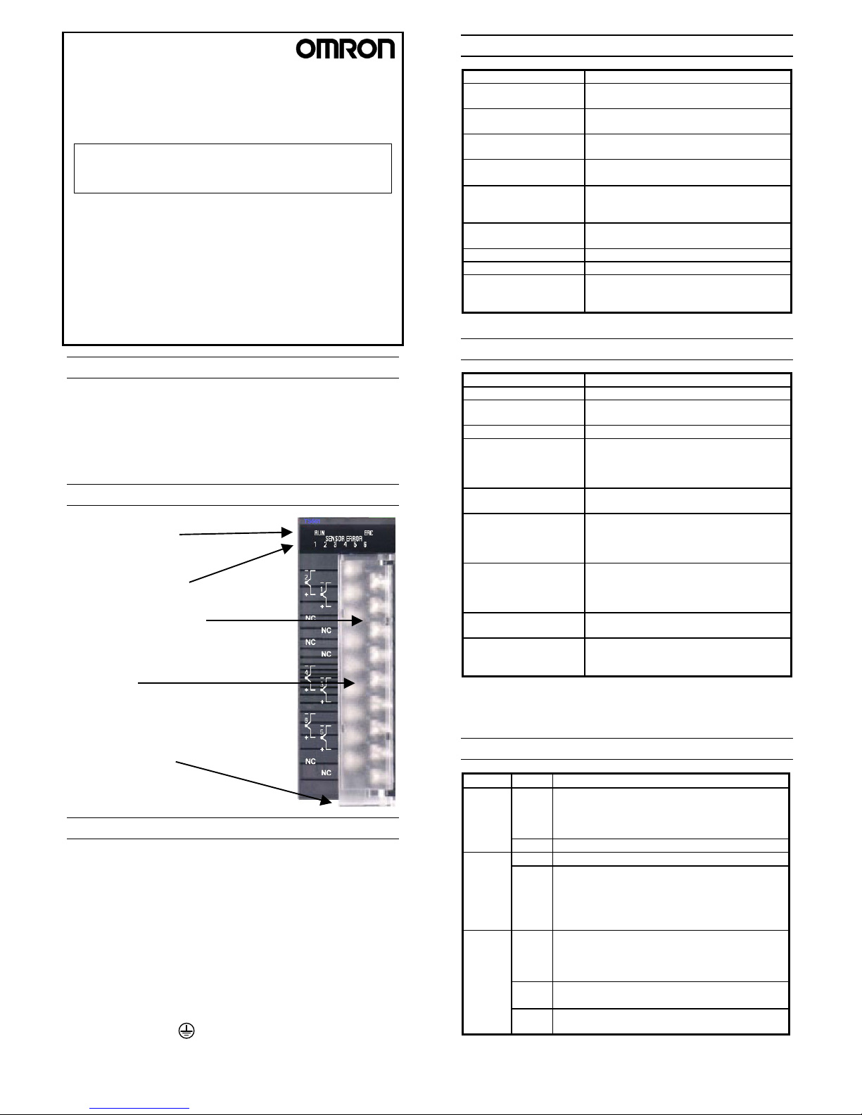
■ Nomenclature
Unit status indicators
• RUN (green)
• ERC (red)
Sensor error indicators
• 1 - 6 (red)
Removable Terminal Block
• Connections for Thermocouples 1 - 6
• CJ1W-TS561: screw terminal
• CJ1W-TS561 (SL): screwless terminal
DIP switches
(remove terminal block for access)
• Select input types (K-type/J-type)
• Select filter functions
• Select number of active inputs (1-6)
Terminal Block latch
• Slide down to remove
• Slide up to lock
* Indication accuracy is guaranteed with the supplied terminal block.
Do not replace the supplied terminal block by a different model (e.g.
screw type by screwless type or vice versa).
■ LED indicators
Name State Description
OFF Fatal error or no power supply.
• Check the host PLC’s CPU status, and the
status of other I/O units. If all other units
function normally, replace the Unit.
RUN
(Green)
ON
Unit functions normally.
OFF
No fatal errors.
ERC
(Red)
ON Incorrect DIP switch setting
Fatal error in the Unit.
• Check the CPU unit for error codes.
• Re-start the PLC system.
• If the ERC LED is still lit, replace the unit.
OFF
• Measurement of the corresponding channel is
within range, or
• Channel has been deactivated by DIP switch
settings
ON
• Measured temperature out-of-range, or
• Thermocouple broken wire
Sensor
Error
1 – 6
(Red)
All ON Calibration data not found or incorrect. The Unit
should be returned to OMRON for calibration.
■ Wiring
• Keep the thermocouple wiring as short as possible to avoid
electrical interference. Shielded wiring is recommended.
• When extending input wiring, always use compensation wires
appropriate for the thermocouple type.
• For activated but unused inputs, short-circuit the + and terminals, to prevent unstable readout on the other inputs.
• Keep the input wiring away from power lines including AC power
supply lines and high-power lines. Do not run the I/O lines in the
same duct or conduit as power lines.
• The input circuits are galvanically isolated from the PLC’s I/O bus,
but there is no galvanic isolation between individual inputs.
• Always ground the terminal on the Power Supply Unit of the
PLC. In case of shielded sensor wiring, connect the shields to the
same grounding point as the PLC.
Page 2
Measure Cold Junction
+ Sensor error check
Measure Channel 1
Measure Channel 2
Measure Channel N
Unit initialisation
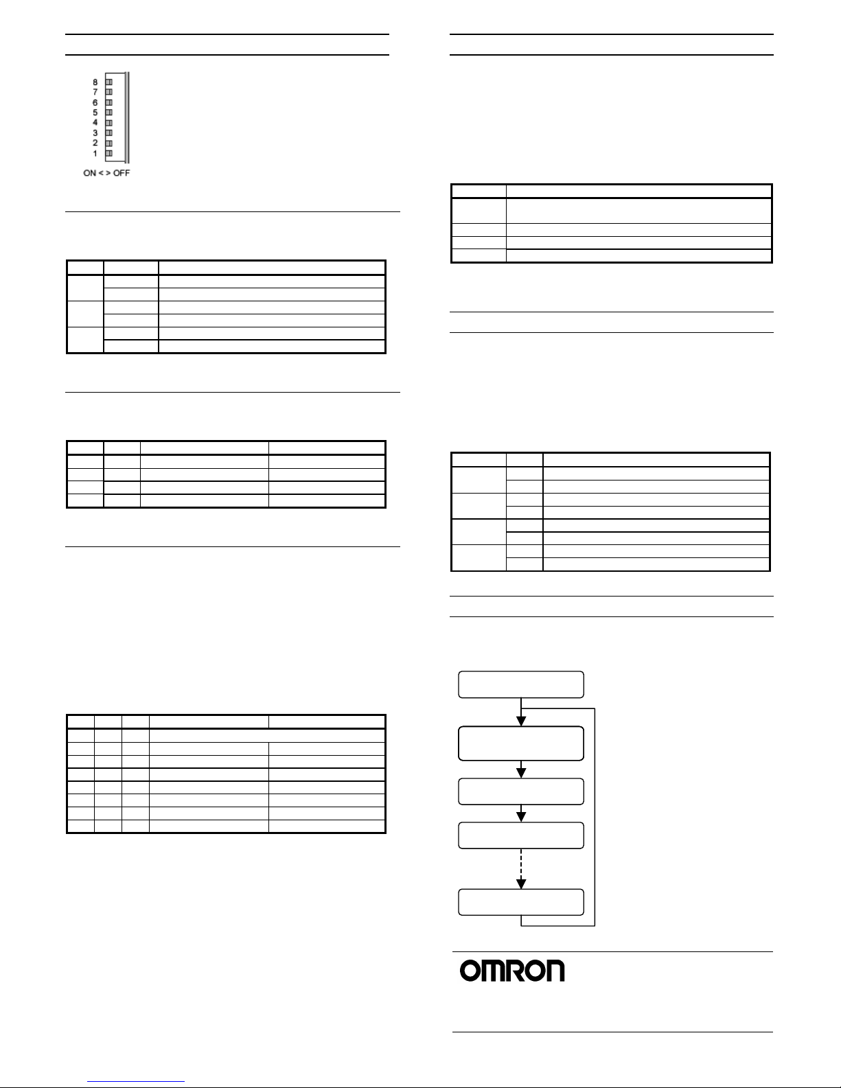
■ DIP switches
8 DIP switches are accessible after removing the
front terminal block. Switch settings are processed at
time of power ON, and should not be changed while
the unit is powered.
Default (ex-factory) setting is all switches ON,
i.e. all 6 inputs are active and set to K-type
thermocouple, with filtering at n x 100 Hz. Be sure
to adjust the settings to your requirements before
use.
SW 1, 2 and 3 : Input type selection
Any combination of input types (different numbers of K-type/J-type
sensors) can be set.
SW State Input type selection
OFF Input channel 1 is J-type 1
ON Input channel 1 is K-type
OFF Input channels 2 and 3 are J-type 2
ON Input channels 2 and 3 are K-type
OFF Input channels 4, 5 and 6 are J-type 3
ON Input channels 4, 5 and 6 are K-type
SW 4 + 5 : Input filtering (valid for all active input channels)
Use filtering if the measured value is affected by the mains frequency or
other sources of electrical interference.
SW4 SW5 Filtering Response time
OFF OFF n x 10 Hz suppression 400 ms each input
OFF ON n x 50 Hz suppression 80 ms each input
ON OFF n x 60 Hz suppression 67 ms each input
ON ON n x 100 Hz suppression 40 ms each input
SW 6+7+8 : Input activation
To prevent broken wire indication for unused inputs, and to reduce the
number of input channels occupied in CIO memory, the number of
required inputs can be set by SW 6+7+8.
Input words are allocated in the PLC’s CIO area as Basic I/O Unit, i.e.
sequentially starting at the leftmost unit. See CJ1-series Operation
Manual W393 for details.
Create the I/O table in the PLC after changing the switch settings, to
register the correct number of input words in the PLC CPU. The unit is
registered as 48-point, 64-point, or 96-point input unit, depending on the
number of 16-bit CIO words it occupies.
SW6 SW7 SW8 Active inputs Occupied input words
OFF OFF OFF Not valid, ERC indicator will be ON
ON OFF OFF 1 3 CIO words (1 used)*
OFF ON OFF 1, 2 3 CIO words (2 used)*
ON ON OFF 1, 2, 3 3 CIO words
OFF OFF ON 1, 2, 3, 4 4 CIO words
ON OFF ON 1, 2, 3, 4, 5 6 CIO words (5 used)*
OFF ON ON 1, 2, 3, 4, 5, 6 6 CIO words
ON ON ON 1, 2, 3, 4, 5, 6 6 CIO words
* In these cases, more CIO words will be occupied than required for the
active inputs. The remaining occupied CIO words will be filled with 0’s,
and cannot be used as work bits.
■ Data representation
Measured temperatures are indicated in °C. Each input value
occupies one word (16 bits) in the CIO area and is encoded as a
signed integer, with a resolution of 0.1 °C.
Examples: #0300 = 768 (dec) = 76.8 °C
#FF85 = -123 (dec) = -12.3 °C
Measured values are updated in CIO memory in each I/O refresh cycle.
The following values are to be interpreted as error codes:
Value Description
#7AAA Calibration data invalid or error detected at start-up,
e.g. cold junction temperature out of range.
#7BBB Sensor error, broken wire
#7CCC Measured value out of range (over max. Temperature)
#8CCC Measured value out of range (under min. Temperature)
During initialisation after power ON, data of active inputs will be #0000
until the “Not Ready’ flag turns OFF.
■ ‘Not Ready’ flag
During initialisation after power-on, and in case of internal failure, a
‘Not Ready’ flag will be set in the PLC memory area A050 to A069
(Basic I/O Unit information area, refer to CJ1 Operation Manual W393
for details).
The lower bit of each unit is the Not Ready flag; the error code
indicated in the remaining bits is relevant for repair purposes only.
While this flag is ON, the temperature sensor data indicated by the
unit in the CIO area is invalid.
Address Bit When Bit = ON
00 Unit in rack 0, slot 0 is not ready A050
08 Unit in rack 0, slot 1 is not ready
00 Unit in rack 0, slot 2 is not ready A051
… …
00 Unit in rack 1, slot 0 is not ready A055
… …
00 Unit in rack 3, slot 9 is not ready A069
08 Unit in rack 3, slot 10 is not ready
■ Unit cycle time
The internal processing time for all measurements by the unit is
determined by the number of active channels and the filter type.
The cold junction compensation
measurement and one sensor error
check are executed each cycle.
The cold junction measurement
time depends on the input filter
setting, whereas the sensor error
check takes a fixed 40 ms.
Example:
If 4 inputs are active, and filtering is
set to n x 50 Hz (response time =
80 ms):
Each measurement cycle takes
(4+1) x 80 + 40 ms = 440 ms.
OMRON CORPORATION
Note: Specification subject to change without notice Printed in The Netherlands 1634299-2A
OMRON ELECTRONICS LLC
Phone: 1-847-843-7900 or
1-800-55-OMRON
OMRON CANADA INC.
Phone: 416-286-6465
Phone: 1-514-636-6676 (French)
 Loading...