

Page 1

W903-E2-02
C200HW-MC402-E
Motion Control Unit
Operation Manual
Page 2

C200HW-MC402-E
Motion Control Unit
Operation Manual
Produced June 2001
Page 3

Notice:
OMRON products are manufactured for use according to proper procedu res by a qualified operator
and only for the purposes described in this manual.
The following conventions are used to indicate and classify precautions in this manual. Always heed
the information provided with them. Failure to heed precautions can result in injur y to p eople or damage to property.
!DANGER
!WARNING
!Caution
Indicates an imminently hazardous situation which, if not avoided, will result in death or
serious injury.
Indicates a potentially hazardous situation which, if not avoided, could result in death or
serious injury.
Indicates a potentially hazardous situation which, if not avoided, may result in minor or
moderate injury, or property damage.
OMRON Product References
All OMRON products are capitalized in this manual. The word “Unit” is also capitalized when it refers to
an OMRON product, regardless of whether or not it appears in the proper name of the product.
The abbreviation “Ch”, which appears in some displays and on some OMRON products, often means
“word” and is abbreviated “Wd” in documentation in this sense.
The abbreviation “PC” means Programmable Controller and is not used a s an abbreviation for anything else.
Visual Aids
The following headings appear in the left column of the manual to help you locate different types of
information.
Note Indicates information of par ticular interest for efficient and convenient opera-
tion of the product.
1,2,3... Indicates lists of one sort or another, such as procedures, checklists, etc.
OMRON, 2001
All rights reserved. No part of this publication may be reproduced, stored in a retrieval system, or transmitted, in
any form, or by any means, mechanical, electronic, photocopying, recording, or otherwise, without the prior
written permission of OMRON.
No patent liability is assumed with respect to the use of the information contained herein. Moreover, because
OMRON is constantly striving to improve its high-quality products, the information contained in this manual is
subject to change without notice. Every precaution has been taken in the preparation of this manual. Nevertheless, OMRON assumes no responsibility for errors or omissions. Neither is any liability assumed for damages
resulting from the use of the information conta ined in this publication.
v
Page 4

TABLE OF CONTENTS
PRECAUTIONS . . . . . . . . . . . . . . . . . . . . . . . . . . . . . . . . xi
1 Intended Audience . . . . . . . . . . . . . . . . . . . . . . . . . . . . . . . . . . . . . . . . . . . . . . . . . xii
2 General Precautions . . . . . . . . . . . . . . . . . . . . . . . . . . . . . . . . . . . . . . . . . . . . . . . . xii
3 Safety Precautions. . . . . . . . . . . . . . . . . . . . . . . . . . . . . . . . . . . . . . . . . . . . . . . . . . xii
4 Operating Environment Precautions . . . . . . . . . . . . . . . . . . . . . . . . . . . . . . . . . . . . xiii
5 Application Precautions . . . . . . . . . . . . . . . . . . . . . . . . . . . . . . . . . . . . . . . . . . . . . xiii
6 Conformance to EC Directives . . . . . . . . . . . . . . . . . . . . . . . . . . . . . . . . . . . . . . . . xv
SECTION 1
Features and System Configuration . . . . . . . . . . . . . . . . 1
1-1 Features . . . . . . . . . . . . . . . . . . . . . . . . . . . . . . . . . . . . . . . . . . . . . . . . . . . . . . . . . . 2
1-2 System Configuration . . . . . . . . . . . . . . . . . . . . . . . . . . . . . . . . . . . . . . . . . . . . . . . 4
1-3 Motion Control Concepts . . . . . . . . . . . . . . . . . . . . . . . . . . . . . . . . . . . . . . . . . . . . 5
1-4 Control System . . . . . . . . . . . . . . . . . . . . . . . . . . . . . . . . . . . . . . . . . . . . . . . . . . . . 14
1-5 Specifications . . . . . . . . . . . . . . . . . . . . . . . . . . . . . . . . . . . . . . . . . . . . . . . . . . . . . 18
1-6 Comparison with C200HW-MC402-UK . . . . . . . . . . . . . . . . . . . . . . . . . . . . . . . . 20
SECTION 2
Installation. . . . . . . . . . . . . . . . . . . . . . . . . . . . . . . . . . . . . 23
2-1 Components and Unit Settings . . . . . . . . . . . . . . . . . . . . . . . . . . . . . . . . . . . . . . . . 24
2-2 Installation. . . . . . . . . . . . . . . . . . . . . . . . . . . . . . . . . . . . . . . . . . . . . . . . . . . . . . . . 25
2-3 Wiring . . . . . . . . . . . . . . . . . . . . . . . . . . . . . . . . . . . . . . . . . . . . . . . . . . . . . . . . . . . 26
2-4 Servo System Precautions . . . . . . . . . . . . . . . . . . . . . . . . . . . . . . . . . . . . . . . . . . . . 36
2-5 Wiring Precautions . . . . . . . . . . . . . . . . . . . . . . . . . . . . . . . . . . . . . . . . . . . . . . . . . 38
SECTION 3
PC Data Exchange . . . . . . . . . . . . . . . . . . . . . . . . . . . . . . 41
3-1 IR/CIO Area Allocation . . . . . . . . . . . . . . . . . . . . . . . . . . . . . . . . . . . . . . . . . . . . . 42
3-2 Overview of Data Exchanges . . . . . . . . . . . . . . . . . . . . . . . . . . . . . . . . . . . . . . . . . 46
3-3 Details of the Data Exchange Methods. . . . . . . . . . . . . . . . . . . . . . . . . . . . . . . . . . 48
SECTION 4
Multitasking BASIC Programming . . . . . . . . . . . . . . . . 57
4-1 Overview . . . . . . . . . . . . . . . . . . . . . . . . . . . . . . . . . . . . . . . . . . . . . . . . . . . . . . . . . 58
4-2 BASIC Programming . . . . . . . . . . . . . . . . . . . . . . . . . . . . . . . . . . . . . . . . . . . . . . . 58
4-3 Motion Control Application . . . . . . . . . . . . . . . . . . . . . . . . . . . . . . . . . . . . . . . . . . 61
4-4 Command Line Interface. . . . . . . . . . . . . . . . . . . . . . . . . . . . . . . . . . . . . . . . . . . . . 65
4-5 BASIC Programs. . . . . . . . . . . . . . . . . . . . . . . . . . . . . . . . . . . . . . . . . . . . . . . . . . . 65
4-6 Error Processing . . . . . . . . . . . . . . . . . . . . . . . . . . . . . . . . . . . . . . . . . . . . . . . . . . . 68
vii
Page 5

TABLE OF CONTENTS
SECTION 5
BASIC Motion Control Programm ing Langua ge . . . . . 71
5-1 Notation Used in this Section . . . . . . . . . . . . . . . . . . . . . . . . . . . . . . . . . . . . . . . . 75
5-2 Classifications and Outlines . . . . . . . . . . . . . . . . . . . . . . . . . . . . . . . . . . . . . . . . . 75
5-3 Command, function and parameter description. . . . . . . . . . . . . . . . . . . . . . . . . . . 84
SECTION 6
Programming Environment . . . . . . . . . . . . . . . . . . . . . . . 157
6-1 Motion Perfect Features. . . . . . . . . . . . . . . . . . . . . . . . . . . . . . . . . . . . . . . . . . . . . 158
6-2 Motion Perfect Requirements . . . . . . . . . . . . . . . . . . . . . . . . . . . . . . . . . . . . . . . . 158
6-3 Going Online with the MC Unit . . . . . . . . . . . . . . . . . . . . . . . . . . . . . . . . . . . . . . 158
6-4 Motion Perfect Projects . . . . . . . . . . . . . . . . . . . . . . . . . . . . . . . . . . . . . . . . . . . . . 159
6-5 Motion Perfect Desktop. . . . . . . . . . . . . . . . . . . . . . . . . . . . . . . . . . . . . . . . . . . . . 161
6-6 Motion Perfect Tools . . . . . . . . . . . . . . . . . . . . . . . . . . . . . . . . . . . . . . . . . . . . . . . 164
6-7 Suggestions and Precautions in Using Motion Perfect . . . . . . . . . . . . . . . . . . . . . 177
SECTION 7
Troubleshooting. . . . . . . . . . . . . . . . . . . . . . . . . . . . . . . . . 179
7-1 Problems and Countermeasures. . . . . . . . . . . . . . . . . . . . . . . . . . . . . . . . . . . . . . . 180
7-2 Error Indicators . . . . . . . . . . . . . . . . . . . . . . . . . . . . . . . . . . . . . . . . . . . . . . . . . . . 184
7-3 Error Handling. . . . . . . . . . . . . . . . . . . . . . . . . . . . . . . . . . . . . . . . . . . . . . . . . . . . 184
7-4 CPU Unit Error Flags and Control Bits. . . . . . . . . . . . . . . . . . . . . . . . . . . . . . . . . 187
SECTION 8
Maintenance and Inspection. . . . . . . . . . . . . . . . . . . . . . . 189
8-1 Routine Inspections . . . . . . . . . . . . . . . . . . . . . . . . . . . . . . . . . . . . . . . . . . . . . . . . 190
8-2 Handling Precautions. . . . . . . . . . . . . . . . . . . . . . . . . . . . . . . . . . . . . . . . . . . . . . . 191
Appendix
Appendix A Upgrading from C200HW-MC402-UK. . . . . . . . . . . . . . . . . . . . . . . . . 193
Appendix B PC Interface Area Lists . . . . . . . . . . . . . . . . . . . . . . . . . . . . . . . . . . . . . 195
Appendix C Programming Examples. . . . . . . . . . . . . . . . . . . . . . . . . . . . . . . . . . . . . 197
Index. . . . . . . . . . . . . . . . . . . . . . . . . . . . . . . . . . . . . . . . . . 205
Revision History . . . . . . . . . . . . . . . . . . . . . . . . . . . . . . . . 211
viii
Page 6

About this Manual:
This manual describes the installation and operation of the C200HW-MC402-E Motion Control Unit
(MC Unit) and includes the sections described below.
Please read this manual carefully and be sure you understand the information provided before
attempting to install or operate the MC Unit. Be sure to read t he precautions p rovided in the following
section.
Precautions provides general precautions for using the MC Unit, Programmable Controller (PC), and
related devices.
Section 1
to its operation. Also the specifications and the comparison with previous C200HW-MC402-UK is
shown.
Section 2
Section 3
between the MC Unit and the CPU Unit.
Section 4
which programs are managed for the MC Unit.
Section 5
cation using the MC Unit. All BASIC system, task and axis statements that determine the various
aspects of program execution and MC Unit operation are presented.
Section 6
tor and debug motion based applications for the MC Unit.
Section 7
Section 8
Unit operating in optimum cond ition. It also i ncludes proper procedures when replacing an MC Unit or
battery.
The Appendices provide a guide for upgrading from the C200HW-MC402-UK Unit and the PC Interface Lists. Furthermore, some convenient programming examples are given for the user.
describes the function of the C 200HW-MC402-E Motion Cont rol Unit and concepts related
describes information required for hardware setup and installation.
describes the IR/CIO area allocation and presents the di fferent methods of dat a exchange
gives an overview of the fundamentals of multitasking BASIC programs and the methods by
describes the commands and parameters required for programing the motion control appli-
provides an overview of software package Motion Perfect, which is used to program, moni-
provides procedures on troubleshooting problems that may arise with the MC Unit.
explains the maintenance and inspec tion procedures that must be followed to keep the M C
!WARNING
Failure to read and understand the information provided in this manual may result in personal injury ordeath, damage to the product , or product failure. Please read eachsection
in its entirety and be sure you understand the information provided in the section and
related sections before attempting any of the procedures or operations given.
ix
Page 7

PRECAUTIONS
This section provides general precautions for using the Motion Control Unit and related devices.
The information contained in this section is important for the safe and reliable application of the Motio n Control
Unit. You must read this section and understand the information contained before attempting to set up o r o perate
a Motion Control Unit and PC system.
1 Intended Audience . . . . . . . . . . . . . . . . . . . . . . . . . . . . . . . . . . . . . . . . . . . . . xii
2 General Precautions . . . . . . . . . . . . . . . . . . . . . . . . . . . . . . . . . . . . . . . . . . . . xii
3 Safety Precautions. . . . . . . . . . . . . . . . . . . . . . . . . . . . . . . . . . . . . . . . . . . . . . xii
4 Operating Environment Precautions . . . . . . . . . . . . . . . . . . . . . . . . . . . . . . . . xiii
5 Application Precautions . . . . . . . . . . . . . . . . . . . . . . . . . . . . . . . . . . . . . . . . . xiii
6 Conformance to EC Directives . . . . . . . . . . . . . . . . . . . . . . . . . . . . . . . . . . . . xv
6-1-1 Concepts . . . . . . . . . . . . . . . . . . . . . . . . . . . . . . . . . . . . . . . . . . . . . . xv
6-1-2 Conformance to EC Directives . . . . . . . . . . . . . . . . . . . . . . . . . . . . . xvi
xi
Page 8

Intended Audience 1
1 Intended Audience
This manual is intended for the following personnel, who must also have
knowledge of electrical systems (an electrical engineer or the equivalent).
• Personnel in charge of installing FA systems.
• Personnel in charge of designing FA systems.
• Personnel in charge of managing FA systems and facilities.
2 General Precautions
The user must operate the prod uct according to the performance specifications described in the operation manuals.
Before using the product under conditions which are not described in the
manual or applying the product to nuclear control systems, railroad systems,
aviation systems, vehicles, combustion systems, medical equipment, amusement machines, safety equipment, and other systems, machines, and equipment that may have a serious influence on lives and property if used
improperly, consult your OMRON representative.
Make sure that the ratings and performance characteristics of the product are
sufficient for the systems, machines, and equipment, and be sure to provide
the systems, machines, and equipment with double safety mechanisms.
This manual provides information for installing and operating OMRON Motion
Control Units. Be sure to read this manual before operation and keep this
manual close at hand for reference during operation.
!WARNING
It is extremely important that Motion Control Units and related devices be
used for the specified pur pose a nd under t he specified c onditions, especia lly
in applications that can directly or indirectly affect human life. You must consult with your OMRON representative before applying Motion Control Units
and related devices to the above mentioned applications.
3 Safety Precautions
!WARNING
!WARNING
!WARNING
Never attempt to disassemble any Units while power is being supplied. Doi ng
so may result in serious electrical shock or electrocution.
Never touch any of the terminals while power is being supplied. Doing so may
result in serious electrical shock or electrocution.
Provide safety measures in external circuits (i.e., not in the Programmable
Controller or MC Unit) to ensure safety in the system if an abnormal ity occurs
due to malfunction of the PC, malfunction of the MC Un it, or external factors
affecting the operation of the PC or MC Unit. Not providing sufficient safety
measures may result in serious accidents.
• Emergency stop circuits, interlock circuits, limit circuits, and similar safety
measures must be provided in external control circuits.
• The PC or MC Unit outputs may remain ON or OFF due to deposits on or
burning of the output relays, or destruction o f the output transistors. As a
counter-measure for such problems, external safety measures must be
provided to ensure safety in the system.
• When the 24-VDC output (service power supply to the PC) is overloaded
or short-circuited, the voltage may drop and result in the outputs bei ng
turned OFF. As a countermeasure for such problems, external safety
measures must be provi d e d to ensure safety in the system.
xii
Page 9

Operating Environment Precautions 4
• It is the nature of high speed motion control and motion control language
programming and multi-tasking systems, that it is not always possible for
the system to validate the inputs to the func tions. It is the responsibility of
the programmer to ensure that various BASIC s tatements are called c orrectly with the correct number of inputs and that the values are correctly
validated prior to the actual calling of the various functions.
!Caution
!Caution
!Caution
Connect the ENABLE output (drivers enable signal) to the Servo Drivers. Otherwise, the motor may run when the power is turned ON or OFF or when an
error occurs in the Unit.
Do not save data into the flash memor y duri ng me mor y operation or while the
motor is running. Otherwise, unexpected operation may be caused.
Do not reverse the polarity of the 24-V power supply. The polarity must be
correct. Otherwise, the motor may star t running unexpectedly and may not
stop.
4 Operating Environment Precautions
!Caution
!Caution
Do not operate the control system in the following locations:
• Locations subject to direct sunlight.
• Locations subject to temperatures or humidity outside the range specified
in the specifications.
• Locations subject to condensation due to radical temperature changes.
• Locations subject to corrosive or inflammable gases.
• Locations subject to dust (especially iron dust) or salts.
• Locations subject to vibration or shock.
• Locations subject to exposure to water, oil or chemicals.
Take appropriate and sufficient countermeas ures when installing systems in
the following locations:
• Locations subject to static electricity or other sources of noise.
• Locations subject to strong electromagnetic fields.
• Locations subject to possible exposure to radiation.
• Locations near power supply lines.
!Caution
The operating environment of the P C System c an have a large effect on the
longevity and reliability of the system. Improper operating environments can
lead to malfunction, failure, and other unforeseeable problems with the PC
System. Be sure that the operating environment is within the specified conditions at installation and rema ins within the spec ified conditions dur ing the life
of the system.
5 Appli c a tion Precau tions
Observe the following precautions when using the Motion Control Unit or the
PC System.
!WARNING
Failure to abide by the following precautions could lead to serious or possibly
fatal injury. Always heed these precautions.
• Always ground the system to 100 Ω or le ss whe n in sta lling the system to
protect against electrical shock.
xiii
Page 10

Application Precautions 5
• Always turn OFF the power supply to the PC before attempting any of the
following. Not turning OFF the power supply may result in malfunction or
electric shock.
• Mounting or dismounting the MC Unit or any other Units.
• Assembling the Units.
• Setting rotary switches.
• Connecting cables or wiring the system.
• Connecting or disconnecting the connectors.
!Caution
Failure to abide by the following precautions could lead to faulty operation of
the PC, the MC Unit or the system, or could damage the PC or MC Unit.
Always heed these precautions.
• Maximum 12 of the digital inputs (I0 to I15) should be switched on at any
one time to ensure that the Unit remains within internal temperature specifications. Failure to meet this condition may lead to degradation of performance or damage of components.
• After development of the application programs, be sure to save the program data in flash memory within the MC Unit (using the EPROM command in BASIC). The program data will remain in the S-RAM during
operation and power down, but considering possible battery failure it is
advised to store the data in flash memory .
• It is strongly recommended to store dynamic application data, which can
not be initiated in program, in the PC Unit’s memory considering possible
battery failure.
• Do not turn OFF the power supply to the Unit while data is being written to
flash memory. Doing so may cause problems with the flash memory.
• Confirm that no a dverse effect will occur in the system before attempting
any of the following. Not doing so may result in unexpected operation.
• Changing the operating mode of the PC.
• Changing the present value of any word or any set value in memory.
• Force-setting/force-resetting any bit in memory
• Install external breakers and take other safety measures against short-cir-
cuiting in external wiring. Insufficient safety measures against shor t-circuiting may re s ult in burning.
• Be sure that all mounting screws, terminal screws, and cable connector
screws are tightened securely. Incorrect tightening may result in malfunction.
• Before touching the Unit, be sure to first touch a gro unded m etall ic object
in order to discharge any static built-up. Not doing so may result in malfunction or damage.
• Check the pin numbers before wiring the connectors.
• Be sure that the connectors, terminal blocks, I/O cables, cables between
drivers, and other items with locking devices are properly locked into
place. Improper locking may result in malfunction.
• Always use the power supply voltages specified in this manual. An incorrect voltage may result in malfunction or burning.
• Take appropriate measures to ensure that the specified power with the
rated voltage and frequency is supplied. Be pa rticular ly careful in places
where the power supply is unstable. An incorrect power supply may result
in malfun c tion.
• Use crimp terminals for wiring. Do not connect bare stranded wires
directly to terminals. Connection of bare stranded wires may result in
burning.
xiv
Page 11

Conformance to EC Directives 6
• Leave the label attached to the Unit when wiring. Removing the label may
result in malfunction if foreign matter enters the Unit.
• Remove the label after the completion of wiring to ensure proper heat dissipation. Leaving the label attached may result in malfunction.
• Do not apply voltages to the Input Units in excess of the rated input voltage. Excess voltages may result in burning.
• Do not apply voltages or connect loads to the Out put Units in excess of
the maximum switching capacity. Excess voltage or loads may result in
burning.
• Disconnect the functional ground terminal when performing withstand
voltage tests. Not disconnecting the functional ground terminal may result
in burning.
• Double-check all wiring and switch settings before turning ON the power
supply. Incorrect wiring may result in burning.
• Do not pull on the cables or bend the cables beyond their natural limit.
Doing either of these may break the cables.
• Do not place objects on t op of the cables or other wir ing lines. Doing so
may break the cables.
• Resume operation only after transferring to the new MC Unit the contents
of the parameters, position data, and other data required for resuming
operation. Not doing so may result in an unexpected operation.
• Resume operation only after transferring to the new CPU Unit the contents of the DM Area, HR Area, and other data required for resuming
operation. Not doing so may result in an unexpected operation.
• Confirm that set parameters and data operate properly .
• Carefully check the user program before actually running it on the Unit.
Not checking the program may result in an unexpected operation.
• Do not attempt to take any Units apart, to repair any Units, or to modify
any Units in any way.
• Perform wiring according to specified procedures.
6 Conformance to EC Directives
6-1 Applicable Directives
• EMC Directives
• Low Vol tage Directiv e
6-1-1 Concepts
EMC Directives
OMRON devices that comply with EC Directives also conform to the related
EMC standards so that they can be more easily built into other devices or machines. The actual products have been checked for conformity to EMC standards (see the following note). Whether the products conform to the standards in the system used by the customer, however, must be checked by the
customer. EMC-related performance of the OMRON devices that comply with
EC Directives will vary depending on the c onfiguration, wiring, and other conditions of the equipment or control panel in which the OMRON devices are
installed. The customer must, therefore, perform final checks to confirm that
devices and the over-all machine conform to EMC standards.
Note Applicable EMC (Electromagnetic Compatibility) standards are as follows:
EMS (Electromagnetic Susceptibility): EN61131-2
EMI (Electromagnetic Interference): EN50081-2
(Radiated emission: 10-m regulations)
xv
Page 12

Conformance to EC Directives 6
Low Voltage Directive
Always ensure that devices operating at voltages of 50 to 1,000 VAC or 75 to
1,500 VDC meet the required safety standards for the PC (EN61131-2).
6-1-2 Conformance to EC Directives
The C200HX/HG/HE ser ies and CS1 ser ies PCs comply with E C Directives.
To ens ure that the machine or device in which a PC is used complies with EC
directives, the PC must be installed as follows:
1,2,3... 1. The PC must be installed within a control panel.
2. Reinforced insulation or double insulation must be used for the DC power
supplies used for the communications and I/O power supplies.
3. PCs complying with EC Directives also conform to the Common Emission
Standard (EN50081-2). When a PC is built into a machine, however , noise
can be generated by switching devices using relay outputs and cause the
overall machine to fail to meet the Standards. If this occurs, surge killers
must be connected or other measures taken external to the PC.
The following methods represent typical methods for reducing noise, and
may not be sufficient in all cases. Required countermeasures will vary depending on the devices connected to the control panel, wiring , the configuration of th e system, a n d othe r conditions.
xvi
Page 13

SECTION 1
Features and System Configuration
This section des cribes the feature s and system conf igur ation of the C200HW-MC402-E Motion Control Unit and co ncepts
related to its operation. It also indi cates the diff erence with the previous C200HW-MC402-UK Unit.
1-1 Features . . . . . . . . . . . . . . . . . . . . . . . . . . . . . . . . . . . . . . . . . . . . . . . . . . . . . . 2
1-1-1 Overview. . . . . . . . . . . . . . . . . . . . . . . . . . . . . . . . . . . . . . . . . . . . . . 2
1-1-2 Description of Features. . . . . . . . . . . . . . . . . . . . . . . . . . . . . . . . . . . 3
1-2 System Configuration . . . . . . . . . . . . . . . . . . . . . . . . . . . . . . . . . . . . . . . . . . . 4
1-3 Motion Control Concepts . . . . . . . . . . . . . . . . . . . . . . . . . . . . . . . . . . . . . . . . 5
1-3-1 PTP-control. . . . . . . . . . . . . . . . . . . . . . . . . . . . . . . . . . . . . . . . . . . . 7
1-3-2 CP-control. . . . . . . . . . . . . . . . . . . . . . . . . . . . . . . . . . . . . . . . . . . . . 9
1-3-3 EG-Control . . . . . . . . . . . . . . . . . . . . . . . . . . . . . . . . . . . . . . . . . . . . 11
1-3-4 Other Operations. . . . . . . . . . . . . . . . . . . . . . . . . . . . . . . . . . . . . . . . 13
1-4 Control System . . . . . . . . . . . . . . . . . . . . . . . . . . . . . . . . . . . . . . . . . . . . . . . . 14
1-4-1 Feedback Pulses . . . . . . . . . . . . . . . . . . . . . . . . . . . . . . . . . . . . . . . . 14
1-4-2 Servo System Principles . . . . . . . . . . . . . . . . . . . . . . . . . . . . . . . . . . 16
1-5 Specifications . . . . . . . . . . . . . . . . . . . . . . . . . . . . . . . . . . . . . . . . . . . . . . . . . 18
1-6 Comparison with C200HW-MC402-UK . . . . . . . . . . . . . . . . . . . . . . . . . . . . 20
1
Page 14

Features Section 1-1
1-1 Features
1-1-1 Overview
The C200HW-MC402-E Motion Control (MC) Unit is a Special I/O Unit that
can perform
Unit’s multi-tasking BASIC motion control language provides an easy to use
tool for programming advanced motion control applications.
Three types of motion control are possible: point-to-point, continuous path
and electronic gearing.
advanced MC operations on up to four axes simultaneously. The
Point-to-point Control Point-to-point (PTP) control enables positioning independently for each axis.
Axis specific parameters and c ommands are us ed to determi ne the p aths for
the axes.
Continuous Path Control Continuous path (CP) control enables the user not only to control the start and
end positions, but also the path between those points. Possible multi-axis
paths are linear interpolation, circular interpola tion, helical interpolation. Also
user defined paths can be realized with the CAM control.
Electronic Gearing Electronic gearing (EG ) enables controlling an axis as a direct li nk to another
axis. The MC Units supports electronic gear boxing, linked moves and CAM
movements and adding all movements of one axis to another.
The MC Unit can be used in many applications. The following areas have
been identified as applicable areas for the MC Unit.
• Packaging
• Automotive welding
• Coil winding
• Web control
• Cut to length
• Drilling
• Electronic component assembly
• Glue laying
• Flying shears
• Laser guidance
• Milling
• Palletisation
• Tension control
There are many other types of machines that can be controlled by the MC
Unit.
2
Page 15

Features Section 1-1
1-1-2 Descr ip tio n of Feat ures
The MC Unit provides the following features.
Easy Programming with
BASIC Motion Control
Language
A multi-task BASIC motion control language is used to program the MC Unit.
A total of 14 program s can be held i n the Unit an d up to 5 ta sks can be r un
simultaneously. Programs can read a nd writ e to the PC mem ory areas us ing
simple commands from BAS IC or the IORD/IOWR instructions f rom the PC ’s
ladder program.
Windows-based
Programming Software
The MC Unit is programmed using a Windows-based application called
1
Motion Perfect. Motion Perfect allows extremely flexible programming and
debugging.
Virtual Axes The MC Unit contains a total of 8 axes, which consists of 4 servo axes and 4
virtual axes. The virtual axes acts as a perfect servo axes and are used for
computational pur poses for creating profiles. They can be linked directly to
the servo axes.
PC Data Exchange The coordination of the MC Unit with the CPU Unit is largely improved by
modifying the PC Data Exchange interface. The PC Data Exchange interface
now even more allows a centralized control from the PC. The MC Unit uses
the full functionality of the C200HX/HG/HE or CS1 PC. It is now capable of
both exchanging fast control bits via the IR/CIO area as exchanging large
position profile data directly to the MC Unit’s Table array.
Hardware-based
Registration Inputs
There is a high-speed registration input for each axis. On the rising or falling
edge of a registration input, the MC Unit will store the current position in a register. The registered position can then be used by the BASIC program as
required. The registered positions are captured in hardware.
General-purpose Input
and Output Signals
Starting, st opping, limit switching, origin sea rches and many other f unctions
can be controlled without the use of PC I/O. The time required to switch an
output or read an input is thus not dependant on the cycle time. The general
I/O are freely allocable to the different functions.
Reduced Machine Wear The traditional trapezoidal speed profile is provided to generate smooth star t-
ing and stopping. The trapezoidal corners can be rounded off to S-curves.
Trapezoidal Speed Profile
with Square Corners
Time
Trapezoidal S pee d Profil e
with S-curve Corners
SpeedSpeed
Time
1.Motion Perfect is a product of Trio Motion Technology Limited.
3
Page 16
System Configuration Section 1-2
1-2 System Configuration
Basic System
Configuration
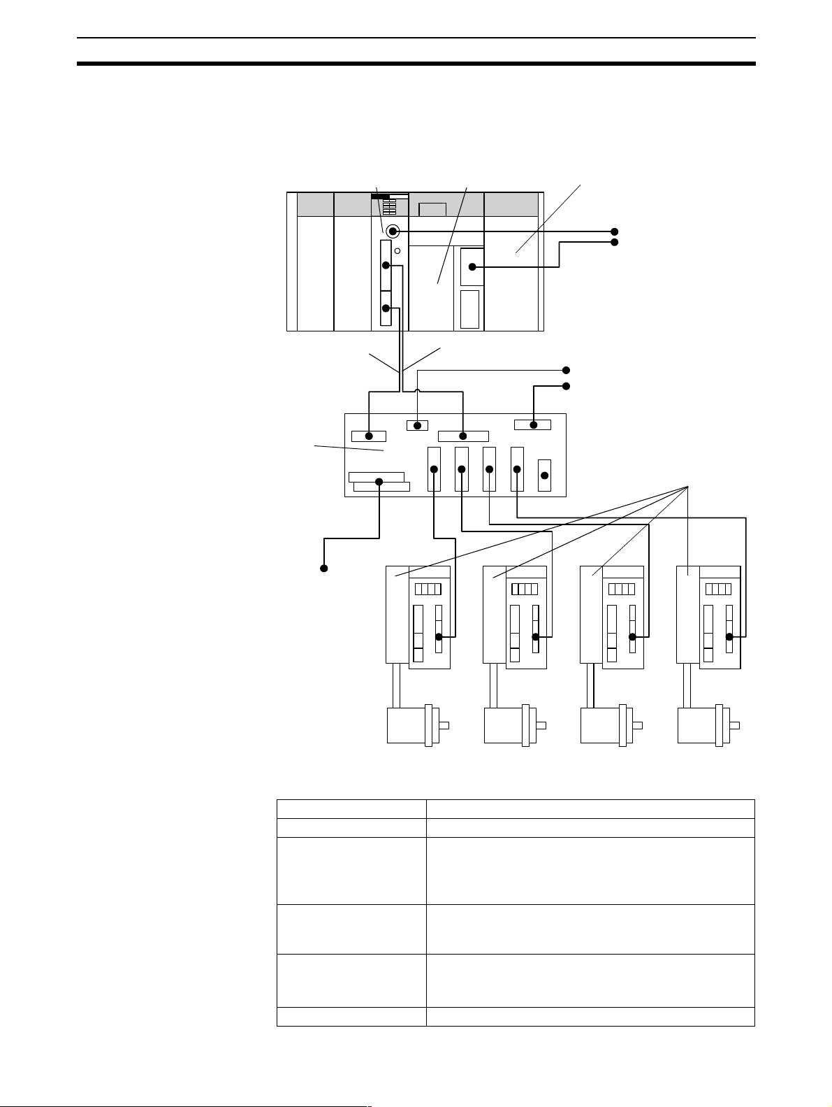
The basic system configuration of the MC Unit is shown below. The diagram
shows the basic physical components of a coordinated mot ion control application.
Power Supply Unit
Computer running
• Motion Perfect
• CX-Programmer
or Syswin
Power supply (24-V) for I/O
Power supply (5/24-V) for Axes
Servo Drivers
Termin al
Block
I/O Cable
MC Unit
CPU Unit
Axis Cable
General
Purpose
I/O
The equipment and models which can be used in the system configuration
are shown in the following table.
Device Model
Motion Control Unit C200HW-MC402-E
CPU Unit Possible models:
C200HX/HG/HE
C200HS
CS1H/CS1G
Power Supply Unit Possib le models:
C200HW-PA204
C200HW-PA204S
CPU Backplane Possible models:
C200HW-BC031/BC051/BC81/BC101
CS1W-BC023/BC033/BC053/BC083/BC103
Terminal Block R88A-TC04-E
4
Page 17

Motion Control Concepts Section 1-3
Device Model
Personal Computer (for
Motion Perfect)
Motion Perfect Version 2.0 or later
Servo Driver R88D-UA, -UT, -W series
Servomotor R88M-UA, -UT, -W series
Inverter 3G3FV in Flux Vector Control
Note 1. The MC Unit cannot be mounted to a C200H PC.
2. The C200HS CPU Units do not support the IORD/IOWR instructions. The
MC Unit can only communicate with a C200HS CPU Unit using the
PLC_READ and PLC_WRITE commands.
3. The MC Unit cannot be mounted to a SYSMAC BUS Slave Rack.
4. The MC Unit can be mounted next to the CPU Unit on the CPU Rack, but
care must be taken to first deter mine the mounting locations of certain
Communications Unit and other Units that require bus connections to the
CPU Unit.
IBM Pers onal Computer or 100% compatible
Cables to be supplied by
the user
The following standard cables are available. A cable can also be prepared by
the user.
Item Model
R88A-CMX001S-E I/O Connection Cabl e fro m MC Unit to Terminal Block (1m)
R88A-CMX001J1-E Axis Connection Cable fr om MC Unit to Terminal Block
(1m)
R88A-CMU001J2-E Connection from Ter minal Block to UA Servo Driver (1m)
R88A-CMUK001J3-E Connection from Terminal Block to UT Servo Driver (1m)
R88A-CMUK001J3-E2 Connection from Terminal Block to UT/W Servo Driver (1m)
R88A-CCM002P4-E Connection Cable RS-232C from MC Unit to computer (2m)
1-3 Motion Control Concepts
The MC Unit offers the following types positioning control operations.
1. Point-to-point control
2. Continuous Path control
3. Electronic Gearing
This section will introduce some of the commands and parameters as use d in
the BASIC programming of the motion control application. Refer to
SECTION 5 BASIC Motion Control Pro g ramming Language for details.
Coordinate System Positioning operations performed by the MC Unit are based on an axis coordi-
nate system. The MC Unit conver ts the encoder edges and pulses from t he
encoder into an internal absolute coordinate system.
The engineering unit which specifies the distanc es of travelling can be freely
defined for each axis separately. The conversion is performed through the
use of the unit conversion factor, which is defined by the UNITS axis parameter. The origin point of the coordinate system can be deter mined using the
DEFPOS command. This com mand re-defines th e current position to zero or
any other value.
A move is defined in either absolute or relative terms. An absolute move takes
the axis to a specific predefined position with respect to the origin point. A relative move takes the axis from the current position to a position that is defined
relative to this current position. The following diagram shows gives an exam-
5
Page 18

Motion Control Concepts Section 1-3
ple of relative (command MOVE) and absolute (command M OVEABS) linear
moves.
MOVEABS(30)
MOVE(60)
MOVEABS(50)
MOVE(50)
MOVE(30)
0
50 100
Axis position
Axis Types The MC Unit has 8 axes in tota l, which can be used for different motion con-
trol purposes depending on the application. Th e type of each axis is determined by the ATYPE axis parameter. The following table lists the different
available axis types.
Axis
type
ATYPE
value
Description
Virtual 0 A virtual axis is used for computational purposes to cre-
ate a move profile without physical movement on any
actual Servo Driver. All move commands and axis
parameters available for the servo axis are also available for the virtual axis and the v ir t ual axis behaves like
a perfect servo axis (demanded po sition is eq ual to the
actual position).
Possible application for the virtual axis is having a virtual move profile added to a servo axis or to test a
developed application before controlling the actual
motors.
Axis range: [0, 7]
Servo 2 The servo axis controls the connected Servo Driver.
Based on the calculated movement profile and the
measured position feedback of the Servomotor the
proper speed reference is outputted to the Servo Driver.
Axis range: [0, 3]
Encoder 3 The encoder axis defines an axis which provides an
encoder input without the servo control speed reference
output to the system. An encode r can be c onnected for
measurement, registration and/or synchron ization functions.
Axis range: [0, 3]
Refer to 1-4 Control System for details on the servo system and encoder
feedback signals. Axes 0 to 3 are servo axes by default and axes 4 to 7 are
fixed as virtual axes.
6
Page 19
Motion Control Concepts Section 1-3
1-3-1 PTP-control
In point-to-point positioning, each axi s is moved independently of the other
axis. The MC Unit supports the following operations.
• Relative move
• Absolute mo ve
• Continuous move forward
• Continuous move reverse
Relative and Absolute Moves
To m ove a single axis either the command MOVE for a relative move or the
command MOVEABS for an absolute move is used. Each axis has its own
move characteristics, which are defined by the axis parameters.
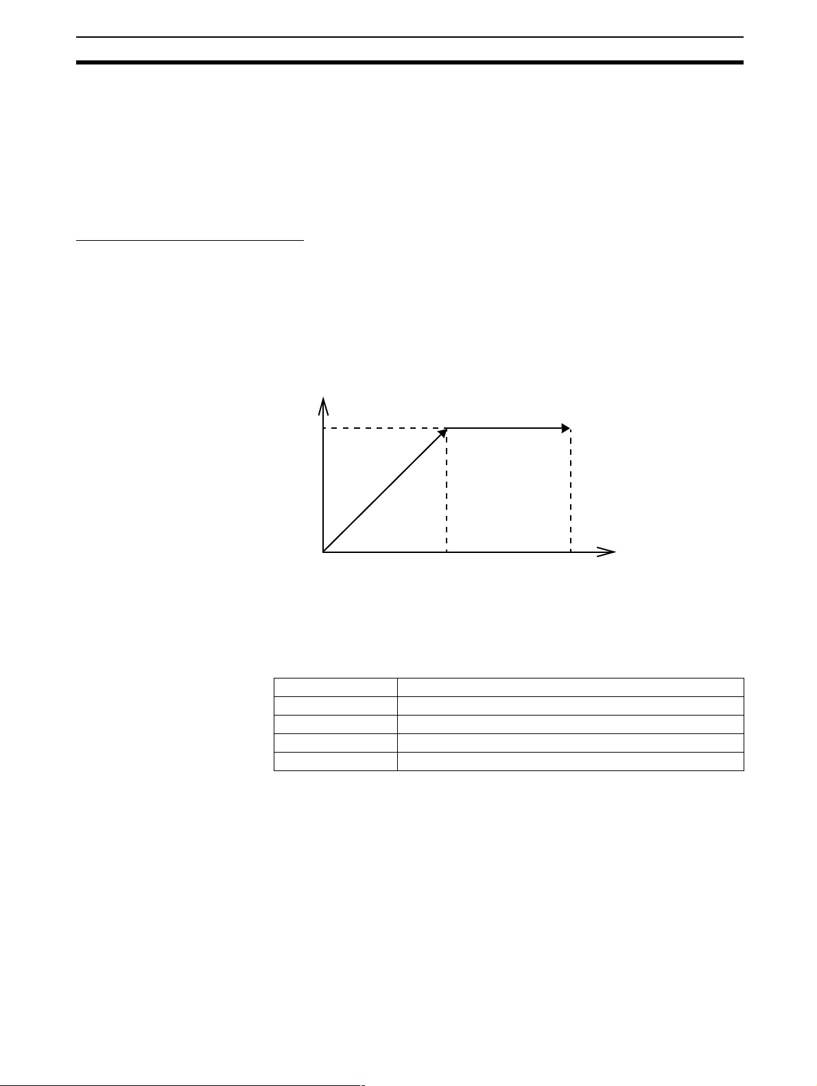
Suppose a control program is executed to move from the origin to an axis
no. 0 coordinate of 100 and axis no. 1 coordinate of 50. If the speed parameter is set to be the s ame for both axes and the acceleration and dec eleration
rate are set sufficiently high, the m ovements for axis 0 and axis 1 will be as
illustrated below.
Axis 1
50
MOVEABS(100) AXI S(0)
MOVEABS(50) AXIS(1)
0
50
100
Axis 0
At start, both the axis 0 and axis 1 will move to a coordinate of 50 over the
same duration of time. At this point, axis 1 will stop and the axis 0 will continue to move to a coordinate of 100.
Relevant Axis Parameters As mentioned before the move of a certain axis is determined by the axis
parameters. Some relevant parameters are given in the next table.
Parameter Description
UNITS Unit conver sion factor
ACCEL Acceleration rate of an axis in units/s
DECEL Deceleration rate of an axis in units/s
SPEED Demand speed of an axis in units/s.
2
.
2
.
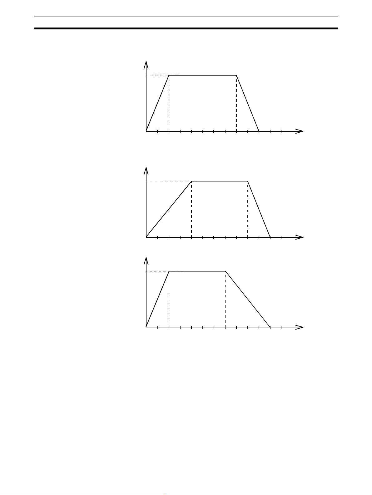
Defining moves The speed profile below shows a simple MOVE operation. The UNITS param-
eter for this axis has been defined for example as meters. The required m aximum speed has been set to 10 m/s. In order to reach this speed in one
second and also to decelerate to zero speed again in one second, both the
acceleration as the deceleration rate have been set to 10 m/s
2
. The total distance travelled is the sum of distances travelled during the acceleration, constant speed and deceleration segm ents. Suppose the distanc e moved by the
7
Page 20
Motion Control Concepts Section 1-3
MOVE command is 40 m, the speed profile will be given by the following
graph.
Speed
ACCEL=10
10
DECEL=10
SPEED=10
MOVE(40)
0
12345
6
Time
The following two speed profiles show the same movement with an acceleration time respectively a deceleration time of 2 seconds.
Speed
ACCEL=5
6
DECEL=10
SPEED=10
MOVE(40)
Time
ACCEL=10
DECEL=5
SPEED=10
MOVE(40)
10
Speed
10
0
12345
0
12345
6
Time
8
Page 21

Motion Control Concepts Section 1-3
D
Vad
Move Calculations The following equations a re used to calculate the total time for the motion of
the axes. Consider the moved distance for the MOVE command as , the
demand speed as , the acceleration rate and deceleration rate .
Acceleration time
V
---=
a
2
Acceleration dist a nc e
V
------=
2a
Deceleratio n time
V
---=
d
2
Deceleration distance
V
------=
2d
Continuous Moves
1-3-2 CP-control
Constant speed distance
V2ad+()
D=
-----------------------–
2ad
D
Total time
The FORWARD and REVERSE commands can be used to start a continuous
movement with constant speed on a cert ain axis. The FORWARD command
will move the axis in positive direction and the REVERSE comman d in negative direction. For these commands also the axis parameters ACCEL and
SPEED apply to specify the acceleration rate and demand speed.
Both movements can be canceled by using either the CANCEL or RAPIDSTOP command. The CANCEL command will cancel the m ove for one axis
and RAPIDSTOP will cancel moves on all axes.
Continuous Path control enables to control a specif ied p ath bet ween t he st art
and end position of a movement for one or multiple axes. The MC Unit supports the following operations.
• Linear interpolation
• Circular interpolation
• Helical interpolation
• CAM control
Va d+()
--- -=
---------------------+
V
2ad
Linear Interpolation
In applications it can be required for a set of motors to perform a move operation from one position to another in a straight line. Linearly interpolated moves
can take place among several axes. The commands MOVE and MOVEABS
are also used for the linear interpolati o n. I n t his c a s e the comma nds will h ave
9
Page 22
Motion Control Concepts Section 1-3
multiple arguments to specify the relative or absolute move for each axis.
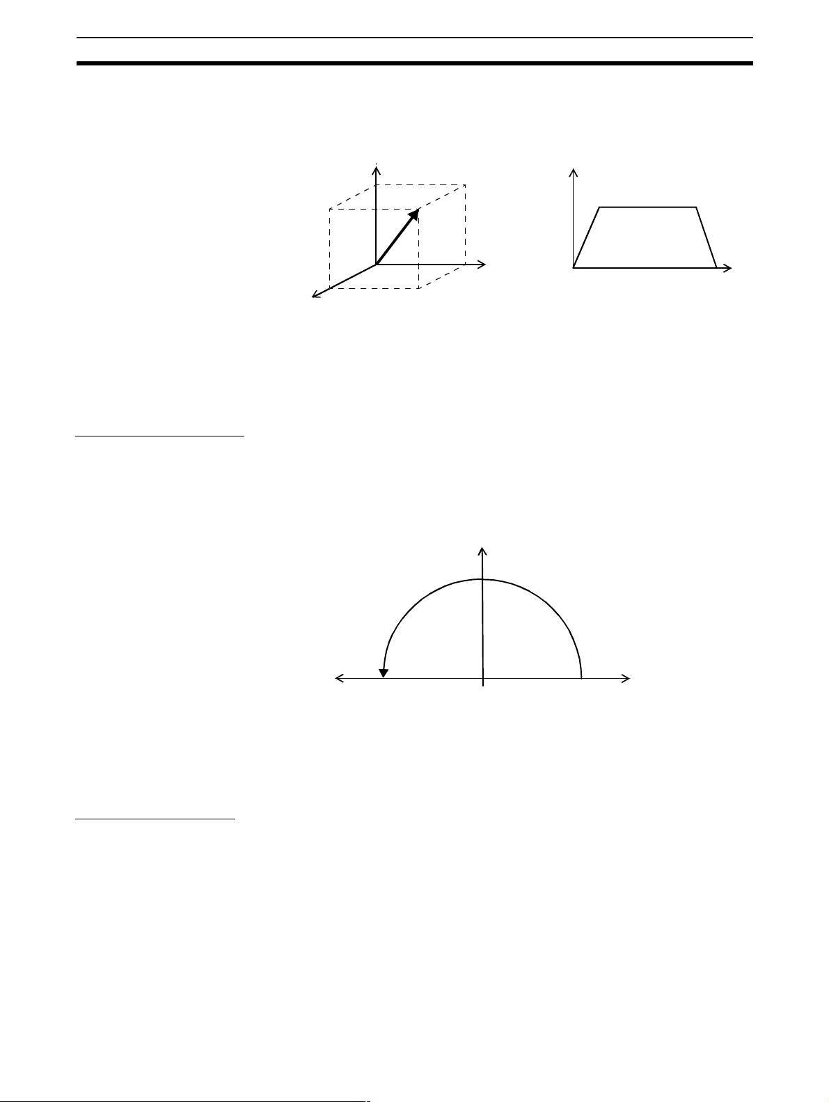
Consider the following three axis move in a 3-dimensional plane.
MOVE(50,50,50)
Axis 2
Axis 1
Axis 0
Speed
Time
The speed profile of the motion along the pa th is given in the diagram. T he
three para meters SPEED, AC CEL a n d DECEL w h ich determine the multi axis
movement are taken from the corresponding parameters of the base axis.
The MOVE command computes the various component s of speed demand
per axis.
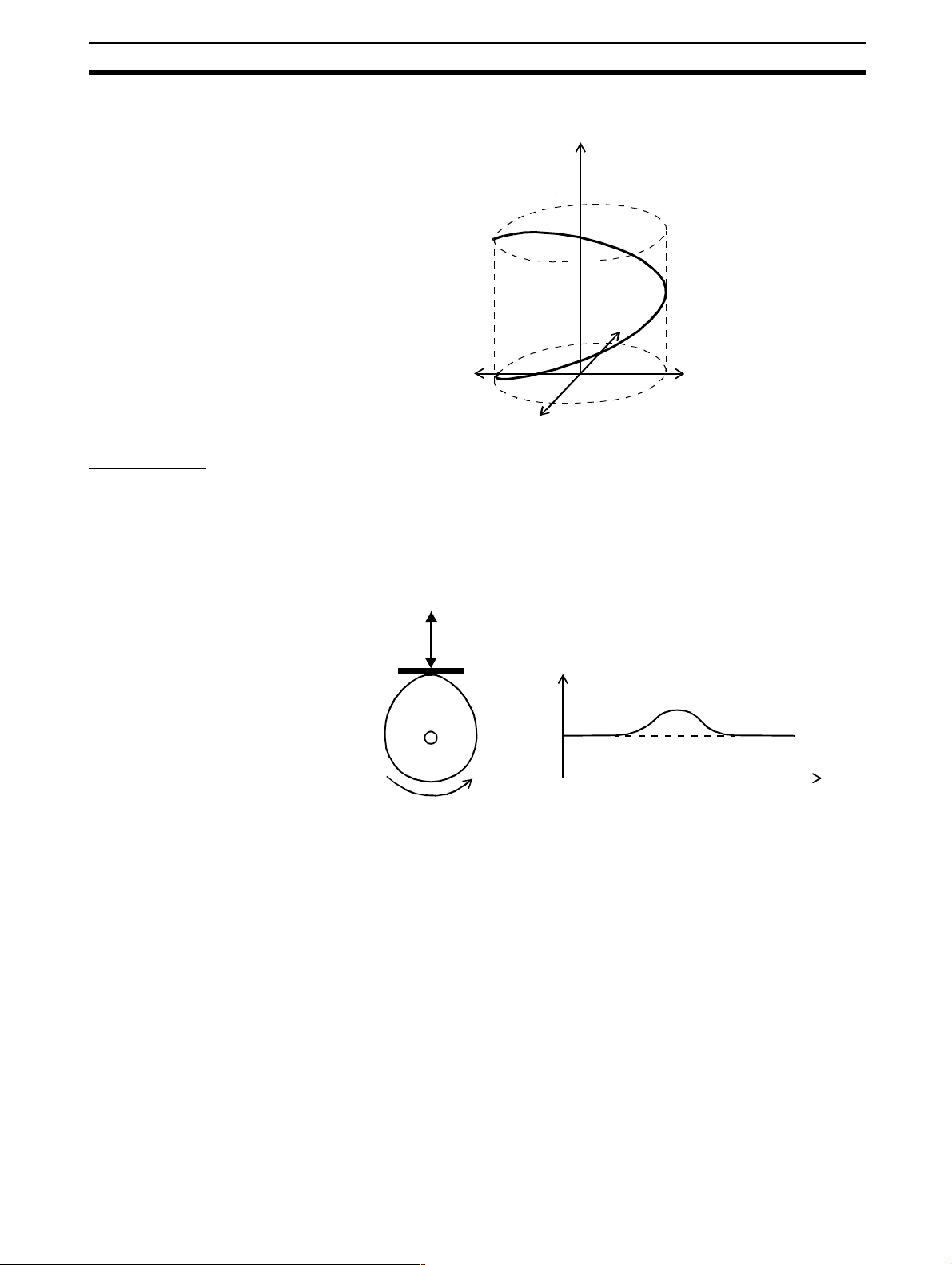
Circular Interpolation
It may be required that a tool travels from the starting point to the end point in
an arc of a circle. In this instance the motion of two axes is related via a circular interpolated move using the MOVECIRC command. Consider the following
diagram.
Helical Interpolation
MOVECIRC(-100,0,-50,0,0)
-50
Axis 1
0
50
50
Axis 0
The centre point and desired end po int of the trajectory relative to the start
point and the direction of movement are specified. The MOVECIRC command
computes the radius and the angle of rotation. Like the linearly inter polated
MOVE command, the ACCEL, DECEL and SPEED variables associated with
the base axis determine the speed profile along the circular move.
Helical interpolation performs a helical movement on three axes. The motion
control c ommand MHELICA L will perform a circular interpo lation to two axis
and will add a linear move to the third axis. Positioning is performed by again
specifying the centre point, end point and direction for the circular distance
10
Page 23
Motion Control Concepts Section 1-3
and the distance for the third axis. The diagram shows helical interpolation in
a three dimensional plane for axes 0 to 2.
MHELICAL(0,0,0,50,0,150)
Axis 0
Axis 2
Axis 1
CAM Control
Additional to the standard move profiles the MC Unit also provides a way to
define a position profile for the axis to move. The CAM command will move an
axis according to position values stored in the MC Unit Table array. The
speed of travelling through the profile is determ ined by the axis pa rameter s of
the axis.
1-3-3 EG-Control
CAM(0,99,100,20)
Position
Time
Electronic Gearing control allows you to create a direct gearbox link or a
linked move between two axes. The MC Unit supports the following operations.
1. Electronic gearbox
2. Linked CAM
3. Linked move
4. Adding axes
11
Page 24
Motion Control Concepts Section 1-3
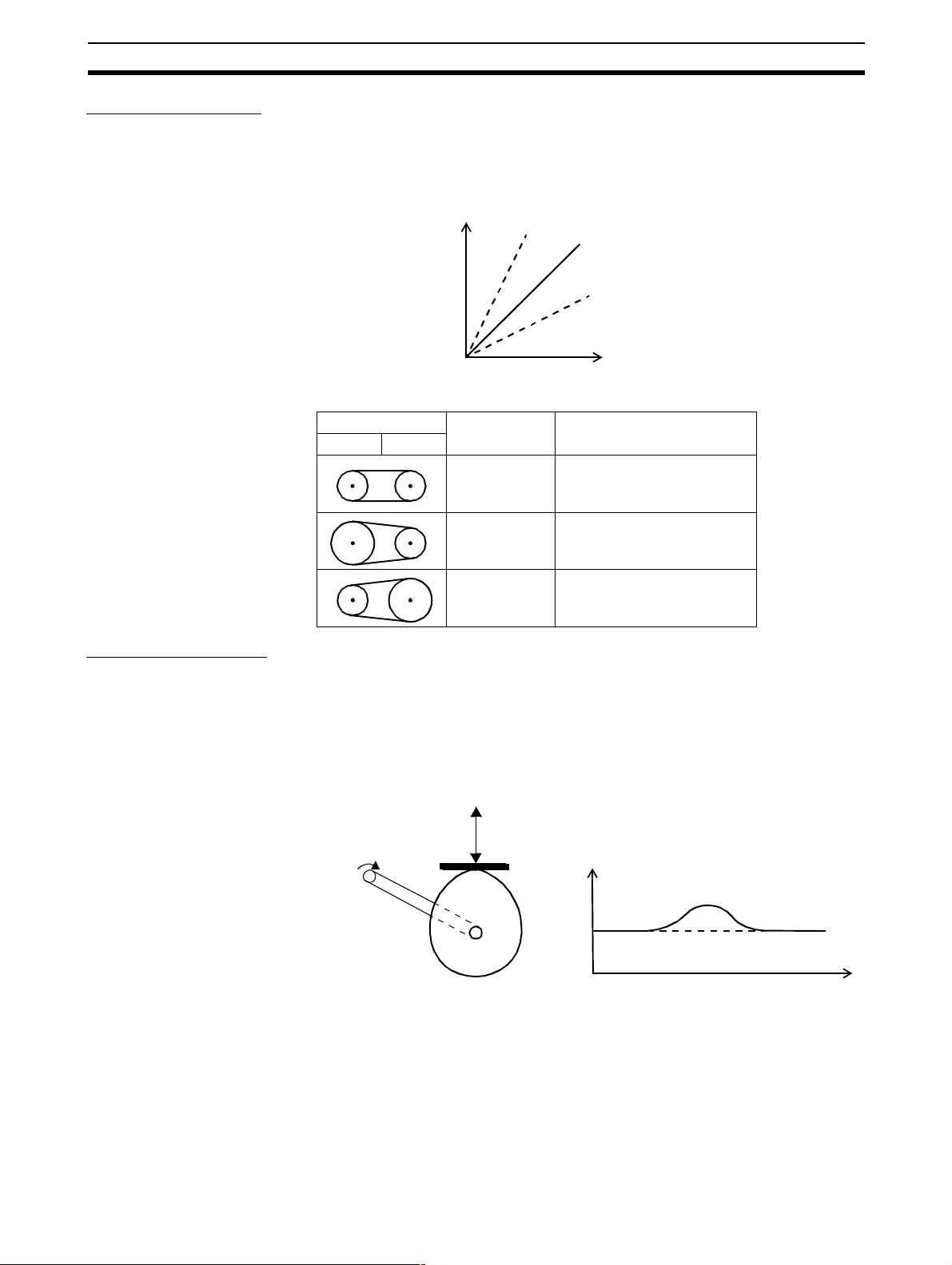
Electronic Gearbox
The MC Unit is able to have a gearbox link from one axis to another as if there
is a physical gearbox connecting them. This can be done using the CONNECT command in the program. In the command the ratio and the axis to link
to are specified.
CONNECT Axis
2:1
Axes Ratio CONNECT command
01
1:1 CONNECT(1,0) AXIS(1)
2:1 CONNECT(2,0) AXIS(1)
1:1
1:2
Master Axis
Linked CAM control
1:2 CONNECT(0.5,0) AXIS(1)
Next to the standard CAM profiling tool the MC Unit also provides a tool to link
the CAM profile to another axis. The command to create the link is called
CAMBOX. The travelling speed through the profile is not deter mined by the
axis parameters of the a xis but by the position of t he linked axis. This is like
connecting two axes through a cam.
CAMBOX(0,99,100,20,0) AXI S(1)
CAMBOX Axis (1) Position
Master Axis (0) Position
12
Page 25
Motion Control Concepts Section 1-3
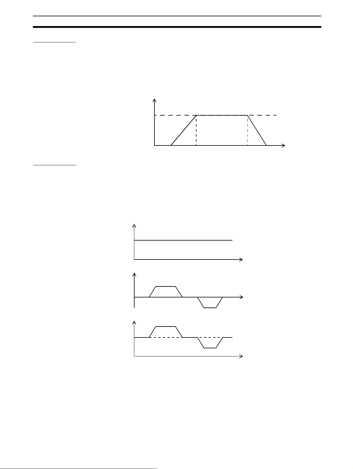
Linked Move
The MOVELINK command provides a way to link a specified move to a master axis. The move is divided into an acceleration, dece leration and constant
speed part and they are specified in master link distances. This can be particularly useful for synchronizing two axes for a fixed period.
MOVELINK(50,60,10,10,0) AXIS(1)
Speed
Master Ax is (0)
Synchronized
MOVELINK Axis (1)
Time
Adding Axes
It is very useful to be able to add all movements of one axis to another. One
possible application is for instance changing the offset between two axes
linked by an electronic gearbox. The MC Unit provides this possibility by using
the ADDAX command. The movements of the linked axis will cons ists of all
movements of the actual axis plus the additional movements of the master
axis.
Speed axis 0*
BASE(0)
ADDAX(2)
FORWARD
MOVE(100) AXIS(2)
MOVE(-60) AXIS(2)
Speed axis 2
Time
+
Speed axis 0
Time
=
Time
1-3-4 Other Operations
Canceling Moves In normal operation or in case of emergency it can be necessary to cancel the
current movement from the buffers. When the CANCEL or RAP IDSTOP commands are g iven, the selected axis respe ctively all axes will canc el thei r current move.
Origin Search The encoder feedback for controlling the position of the motor is incremental.
This means that all movement must be defined with respect to an origin point.
The DATUM command is used to set up a procedure whereby the MC Unit
13
Page 26

Control System Section 1-4
goes through a sequence and searches for the origin based on digital inputs
and/or Z-marker from the encoder signal.
Print Registration The MC Unit can capture t he position of an axis in a regi ster when an event
occurs. The event is referred to as the print registration input. On the risin g or
falling edge of an input signal, which is either the Z-marker or an input, the MC
Unit captures the position of an axis in hardware. This position can then be
used to correct possible error between the actual position and the desired
position. The print registration is set up by using the REGIST command.
The position is captured in hardware, and therefore there is no software overhead and no interrupt service routines, eliminating the nee d to deal with the
associated timing issues. Each servo axis has one registration input.
Merging Move s If the MERGE axis parameter is set to 1, a movement will always be followed
by a subsequent movement without stopping. The following illustrations will
show the transitions of two moves with MERGE value 0 and value 1.
Speed
MERGE=0
Time
Speed
MERGE=1
Time
Jogging Jogging moves the axes at a constant speed forward or reverse by manual
operation of the digital in puts. Different speeds are also selectable by input.
Refer to the FWD_JOG, REV_JOG and FAST_JOG axis parameters.
1-4 Control System
1-4-1 Feedback Pulses
The MC Unit is designed to comply with the standard O MRON Servomotors
which have an incremental encoder output. In this section, the signals produced by an incremental optical quadrature encoder are discussed. Incremental encoders are available in linear as well as the more common rot ary
types.
Incremental Encoders
The incremental encoder are e ncoders for which the output pos ition information is relative to a starting position and only the distance moved is measured.
The main components of the rotary incremental encoder are an encoder disk,
light source and photodete ctors, plus an amplification circuitry to “square-up”
the photodetector output. The encoder disk is im printed with marks or slots
evenly spaced around its perimeter. As the disk rotates, light strikes the photodetector at the passing of each slot or mark. Amplifiers then convert the
photodetector output to square wave form.
Quadrature signals are produced by using two photodetectors, one positioned
precisely one half a slot, or marker width, from the other. So quadrature refers
to two periodic functions separated b y a quarter cycle or 90 .
With this arrangement, the direction of rotation can be easily detected by
monitoring the relative phase of bo th signals. For example, if channel A leads
channel B, then counterclockwise (CCW) movement could be indicat ed. Con-
°
14
Page 27

Control Sy st em Section 1-4
versely, if channel B leads channel A, then clockwise (CW) movement would
be indicated.
Ty pically, rotary encoders also provide an additional Z-mar ker or slot on the
disk used to produce a reference pulse. By properly decoding and counting
these signals, the direction of motion, speed, and relative position of the
encoder can be determined.
The number of output pu lses produced per revolution per channel is equivalent to the number of marks around the disk. This position information is
decoded in encoder edges, which is actually the number of pulses multiplied
by four. The resolution is multiplied because the circuit generates a pulse at
any rising or falling edge of either of the two phase signals.
Decoding
Understanding how the signals generated by a quadrature encoder are
decoded will help considerably when applying the quadrature decoder feature
in an actual situation.
The basic task of the decoder is to provide two counter input lines: one that
produces clock pulses when CCW motion is detected and another that produces clock pulses when CW motion is detected. These clock pulses are supplied to counters in the MC Unit, one for CW counts and one for CCW counts.
The contents of the counters can be compared w ith each ot her by software,
and the relative position of the rotary device can be determined f rom the difference.
One advantage of this approach is that the actual counting is done by hardware devices, freeing the MC Unit for other operations. The MC Unit has only
to periodically read the counter values and to make a quick subtraction.
Decoder Th eory of
Operation
Forward Rotati on
Re vers e Rotat ion
A closer look at the quadrature signals will be helpful. In this example, the
direction of rotation is CCW if phase A leads ph ase B, and CW if phase A
leads phase B.
The decoder circuit detects a transition and generates a pulse on the appropriate counter input channel depending on wheth er the transition is in the CW
or CCW direction. Although time is plotted on the horizontal axis, it is not necessarily linear. The mechanical device may be changing speed as well as
direction.
Phase A
Phase B
Phase A
Phase B
Standard OMRON Servomotors are designed for an advanced A-phase for
forward rotation and an advanced B-phase for reverse rotation. The MC Unit
is designed to comply with this phase advancement, allowing OMRON Ser vo
Driver Connecting Cables to be used without modification.
15
Page 28
Control System Section 1-4
For typical OMRON Servo Drivers, there are 1,000 pulses per revolution. This
implies that there are 4,000 edges per revolution. So there will b e a Z pu lse
every 4,000 edges.
The signals A, B and Z appear physically as A and /A, B and /B and Z and /Z.
These appear as differential signals on twisted-pair wire inputs, ensuring that
common modes are rejected and that the noise level is kept to a minimum.
When using Servomotors by other makers, check carefully the encoder specification for phase advancement. If the definition differs from the ones given
above, reverse the B-phase wiring between the MC Unit and the Servo Driver.
In most case, this should resolve the problem.
1-4-2 Servo System Principles
The servo system used by and the internal operation of the MC Unit are
briefly described be low. Refer to 2-4 Servo System Precautions for precautions related to servo system operation.
Inferred Closed Loop
System or Semi-closed
Loop System
Internal Operation of the
MC Unit
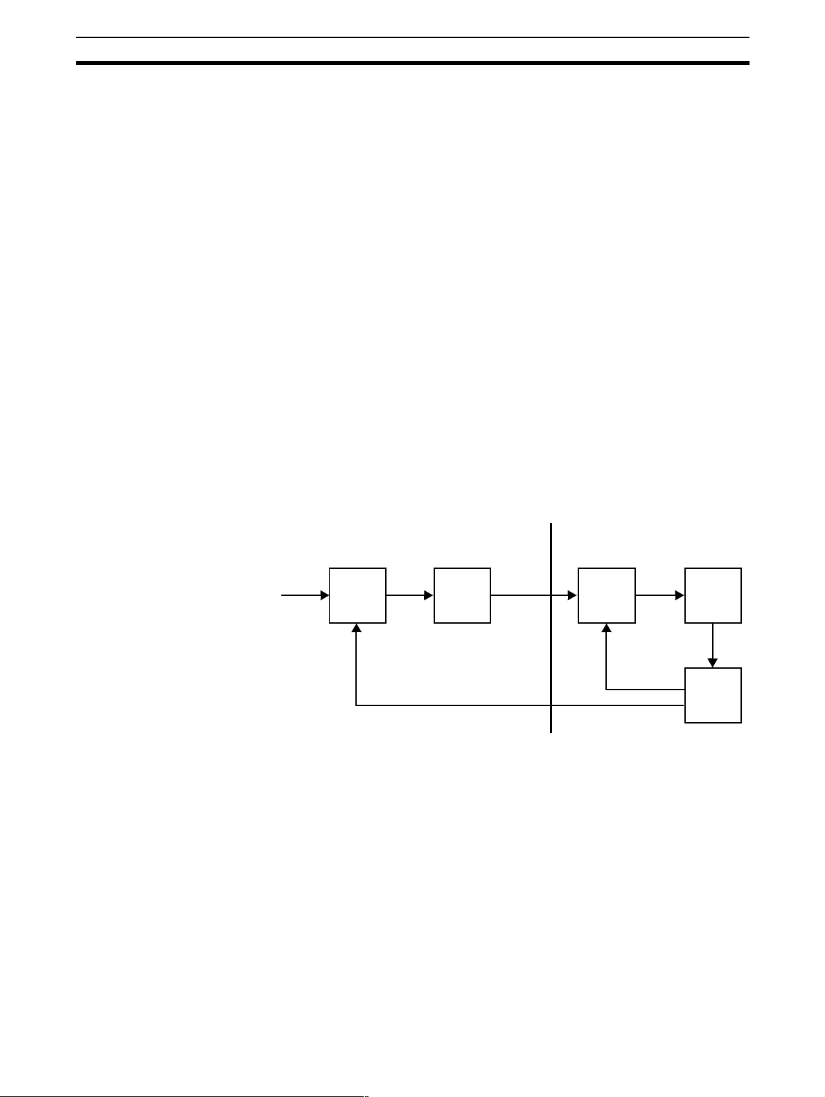
1,2,3... 1. The MC Unit performs actual position control. It receives encoder pulses
The servo system of the MC Unit uses an inferred closed loop system. This
system detects actual machine movements by the rotation of the motor in
relation to a target value. It calculates the error between the target value and
actual movement, and reduces the error through feedback.
Inferred closed loop systems occupy the mainstream i n modern servo systems applied to positioning devices for industrial applications. Commands to
the MC Unit, speed control voltages to the Servo Drivers, and feedback signals from the encoder are described in the next few pages.
Desired
position
MC Unit
12 3
Error
counter
D/A
Converter
Speed
reference
voltage
Servo System
Speed
Control
Motor
4
Speed
feedback
Encoder
Position
feedback
and calculates the required speed reference from the di fference between
the actual position and the desired position.
2. The calculated desired spee d is directly converted by the D/A converter
into an analogue sp eed reference voltage, which is provided to the Servo
Driver.
3. The Servo Driver controls the rotational speed of the Ser vomotor corresponding to the speed reference input.
4. The rotary encod er will generate the feedback pulses for both the spe ed
feedback within the Servo Driver speed loop and the position feedback
within the MC Unit position loop.
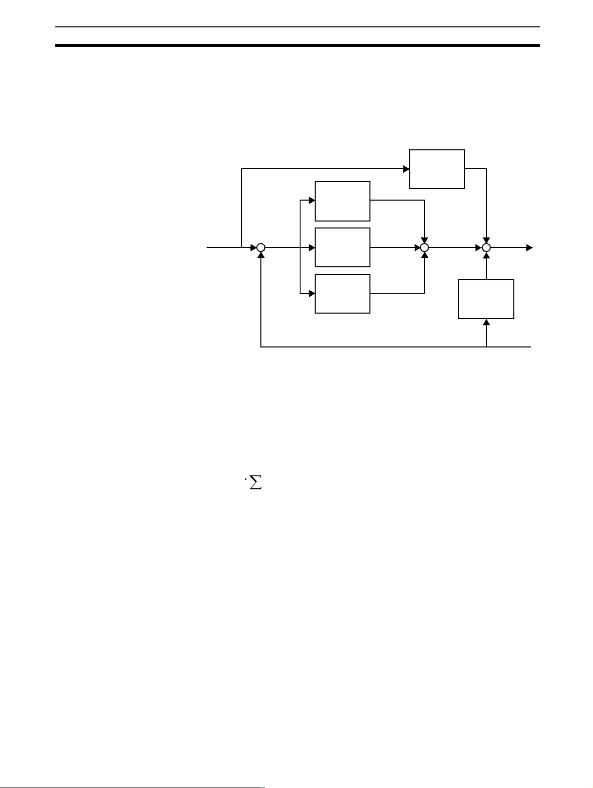
Motion Control Algorithm The servo system controls the motor by continuously adjusting the voltage
output that serves as a spee d reference to the Ser vo Dr iver. The speed reference is calculated by com paring the measured position of the axis from the
encoder with the demand position generated by the MC Unit.
16
Page 29
Control Sy st em Section 1-4
The axis parameters MPOS, DPOS and FE contain the value of respectively
the measured position, demand position and the following error. The following
error is the difference between the demanded and measured position. MC
Unit uses five gain values to control how the servo function generates the voltage output from the following error.
The control algorithm for the motion con trol system of the MC Unit is sho wn in
the diagram below. The five gains are described below.
K
∆
vff
K
p
K
ov
Output
signal
∆
Measured
position
Demand
position
Proportional Gain The proportional gain creates an output that is proportional to the
foll owing er ror .
O
All practical systems use proportional gain. For many just using this gain
parameter alone is sufficient. The proportional gain axis parameter is called
P_GAIN.
Integral Gain The integral gain creates an output t hat is propor tional to the sum of
the following errors that have occurred during the system operation.
O
Integral gain can cause overshoot and so is usually used only on systems
working at constant speed o r with slow accelerations. The integral gain axis
parameter is called I_GAIN.
KpE⋅=
p
K
i
Following
error
+
K
Σ
K
i
∆
d
-
K
p
++
O
p
E
K
i
O
i
E
E
⋅=
i
å
Derivative Gain The derivative gain produces an output that is proportional to the
change in the following error and speeds up the response to changes in
error while maintaining the same relative stability.
O
Derivative gain may create a smoother response. High values may lead to
oscillation. The derivative gain axis parameter is called D_GAIN.
Output Speed Gain The output speed gain produces an output that is proportional to
the change in the measured position and increases system damping.
O
The output speed gain can be us eful for smoothing motions but will gene rate
high following errors. The output speed gain axis parameter is called
OV_GAIN.
d
ov
K
K
d
ov
K
d
E
E∆⋅=
K
ov
P
m
Pm∆⋅=
O
d
O
ov
17
Page 30

Specifications Section 1-5
Speed Feedforward Gain The speed feedforward gain produces an output that is propor-
tional to the change in dem and position and minimizes the following error
K
vff
O
P
d
vff
at high speed.
O
vff
K
vff
Pd∆⋅=
The parameter can be set to minimise the following error at a constant
machine speed after ot her gai ns have been set. Th e speed feed forward gain
axis parameter is called VFF_GAIN.
Default Values The default settings are given below along with the resulting profiles. Frac-
tional values are allowed for gain settings.
Gain Default
Proportional Gain 1.0
Integral Gain 0.0
Der iva tive Gai n 0.0
Output Speed Gain 0.0
Speed Feedforward Gain 0.0
1-5 Specifications
General Specifications
General specifications other than those shown below conform to those for the
SYSMAC C200HS/C200HX/C200HG/C200HE PCs.
Item Specifications
Power supply voltage 5 VDC (from Backplane)
24 VDC (from external power supply)
Voltage fluctuation tolerance 4.75 - 5.25 VDC (from Backplane)
21.6 - 26.4 VDC (from external power supply)
Internal current consu mp tion 600 mA or less for 5 VDC
50 mA or less for 24 VDC
Weight (Connectors excluded) 500 g max.
External Dimensions 130.0 x 35 x 100.5 mm (H x W x D)
Functional Specifications
Type of Unit C200H Special I/O Unit
Applicable PC C200HX/HG/HE and CS1
Backplanes on which MC Unit can be
mounted
Method for data
transfer to CP U
Unit
External connected devices Per sonal computer with Motion Perfect Programming
Controlled Servo Drivers Analogue (speed) input Servo Driver s
Control Control meth od Inferr ed closed loop with incremental encoder and with
18
Item Contents
CPU Backplane
Words allocated in
IR/CIO area
PC and MC Unit
instructions
Maximum No. of axes 8
Maximum No. of
interpolated axes
Maximum No. of
servo axes
Maximum No. of vir-
tual axes
10 words per unit (S ee note 1.)
Any number of words modified by ladder program or
BASIC program instruction
Software
PID , output speed and speed f eed forward gains
8
4
8
Page 31

Specifications Section 1-5
µ
µ
µ
µ
Item Contents
Speed control Speed control of up to 4 axes
Measurement Units User definable
Pos itioning opera-
tions
Encoder interface Line receiver input; maximum response frequency:
Accelerat ion/deceleration curves Trapezoidal or S-curve
External
I/O
Power supply f or general and axis I/O Pr ovided external ly
Task program man-
agement
Linear interpolation Linear interpolation for any number of axes
Circular interpolation Circular interpolation for any two axes
Helical interpolati on Helical interpolation for any three axes
CAM profile CAM profile movement for any axis
Electronic gearbox Electronic gearbox link between any two axes
Linked CAM Linked CAM profile mov em ent for any two axes
Linked move Linked mo ve for any two axes
Adding axes Adding any two axes
250 kp/s (before multiplication)
1 M counts/s (afte r multiplication)
Serial Communication ports
Encoder Line receive inputs:
Servo Driver relationship
General Purpose I/O Up to 16 digital inputs and 8 out puts can be wired to
Registration inputs Each servo axis has a registration input which capture
Programming language
Number of tasks Up to 5 tasks running simultaneously plus the Com-
Max . nu m ber of pr ograms
Data storage capacity 251 (VR) + 16000 (Table) max.
Data transfer to PC
Unit
One RS-232C port for connection to computer wit h the
Motion P erfect software.
One RS-232C port for general purpose.
For four axes (250 kp/s, before mul tiplication)
The foll owing signals are provided.
Inputs:
Driver Alarm Signal (each axis)
Outputs:
Driver Enab le ( all axes)
Speed Reference Voltage (each axis)
Driver Alarm Reset (all axes)
control MC Unit functions. These can include limit
switches, emergency stop switches and proximity
inputs.
the position in hardware. Timing specification (see
note 2):
Digital Input (rising edge): 10 s (max.)
Digital Input (falling edge): 200 s (max.)
Z-marker (rising edge): 2
Z-marker (falling edge): 2
BASIC
mand Line Interface task
14
PLC_READ and PLC_WRITE command in BASIC program, IORD and IOWR instructions in ladder program
in C200HX/HG/HE PCs
s (max.)
s (max.)
19
Page 32

Comparison with C200HW-MC402-UK Section 1-6
Item Contents
Saving program
data
Self diagnostic functions Detection of memory corruption via checksum
MC Unit Battery-backed RAM with flash memory backup.
(See note 3.)
External devi ces Motion Perfect softw are manages a backup on the
hard disk of the personal computer.
Detection of error counter over run
Note 1. The number of MC Units that can be moun ted under on e CPU Unit must
be determined b ased on the maximum number of Special I/O Units that
can be allocated words in the CPU Units, the power supply capacity on the
CPU or Expansion Rack, and the current consumption of the Units mounted to the Rack. Refer to the CPU Unit’s operation manual for details on calculation methods.
2. This specification is the time between the edge in the input signal and the
capture of the position data.
3. The service life for the flash memory is 100,000 writing operations.
1-6 Comparison with C200HW-MC402-UK
The following table shows a comparison between the C200HW-MC402-E Unit
and the previously released C200HW-MC402-UK Unit.
!Caution
The C200HW-MC402-E is not fully backward compatible with the C200HWMC402-UK. Please check Appendix A Upgrading from C200HW-MC402-UK
carefully before upgrading to the C200HW-MC402-E.
Item C200HW-MC402-UK C200HW-MC402-E
Applicable PCs C200HS,C200HX/HG/HE
(HX up to CPU 6 4 )
Supported axes 4 (4 servo) 8 (4 servo and 4 virtual)
Allocated IR/CIO area words 6 words (6 input) 10 words (8 input,
Compatible software Motion Perfect 1.24 and 2.0 Motion Perfect 2.0
Serial Port A Used for Motion Perfect con-
nection and user-defined
communication.
Cyclic Servo Period Set by SERVO_PERIOD
Commands and
instructions
PLC_READ/
PLC_WRITE
IORD/ IOWR Yes
CLEAR_BIT/
SET_BIT/
READ_BIT
param e ter (d efault 1 ms)
Yes Yes
Read/write to MC Unit’s VR
array in one-word format
No Yes
C200HS,C200HX/HG/HE
and CS1
2 output).
- Transfer input and output
words
- General stat us bits shifted
- Modified origin search bits
- Added PC Transfer Error bit
See notes 1 and 2.
Dedicated to Motion Perf ect
connection
Fixed to 1 ms
Also reads/writes al located
IR/CIO area words
Yes
Read/write to MC Unit’s VR
and Table array and oneword and three-word format
supported
Enables bit operation for VR
variables
20
Page 33

Comparison with C200HW- M C402-UK Section 1-6
Item C200HW-MC402-UK C200HW-MC402-E
Commands and
instructions
INPUT/ KEY/
LINPUT
PROC No Yes.
INDEVICE/
OUTDEVICE
CLEAR/ RESET No Yes
APPENDPROG/
AXISVALUES/
EX/
INPUTS0/
INPUTS1/
LOADSYSTEM/
MPE/
STORE
WAIT LOADED/
LIST
No Yes
Added functionality for serial
communications
Allows a process parameter
of a particular task to be
read/written
Yes No
Port 0 is def ault port fo r serial
communication
Commands to clear memory
Yes Commands reserved for
Motion Perfect: descriptions
have been removed from
manual
No Yes
Added functionality
Note 1. The allocation of the IR/C IO area bits has been modi fied in comparison
with the C200HW-MC402-UK. Please refer to 3-1 IR/CIO Area Allocation
and Appendix A Upgrading fr om C200HW-MC402-UK for more information.
2. The names of some IR/CIO area bits have been modified. Unless otherwise indicated, the functionality has not changed. T he names of th e connection pins have been modified without any change in function.
21
Page 34

SECTION 2
Installation
This sectio n des cribes the MC Unit componen ts and provides the information required for installing the MC Unit.
2-1 Components and Unit Settings . . . . . . . . . . . . . . . . . . . . . . . . . . . . . . . . . . . . 24
2-2-1 Installation Method. . . . . . . . . . . . . . . . . . . . . . . . . . . . . . . . . . . . . . 25
2-2-2 Dimensions . . . . . . . . . . . . . . . . . . . . . . . . . . . . . . . . . . . . . . . . . . . . 26
2-2 Installation. . . . . . . . . . . . . . . . . . . . . . . . . . . . . . . . . . . . . . . . . . . . . . . . . . . . 25
2-3-1 Connector Pin Assignments . . . . . . . . . . . . . . . . . . . . . . . . . . . . . . . 26
2-3-2 I/O Specifications . . . . . . . . . . . . . . . . . . . . . . . . . . . . . . . . . . . . . . . 29
2-3-3 Serial Port Connections . . . . . . . . . . . . . . . . . . . . . . . . . . . . . . . . . . 31
2-3-4 Terminal Block . . . . . . . . . . . . . . . . . . . . . . . . . . . . . . . . . . . . . . . . . 32
2-3-5 Connection Examples . . . . . . . . . . . . . . . . . . . . . . . . . . . . . . . . . . . . 34
2-3 Wiring . . . . . . . . . . . . . . . . . . . . . . . . . . . . . . . . . . . . . . . . . . . . . . . . . . . . . . . 26
2-4 Servo System Precautions . . . . . . . . . . . . . . . . . . . . . . . . . . . . . . . . . . . . . . . . 36
2-5 Wiring Precautions . . . . . . . . . . . . . . . . . . . . . . . . . . . . . . . . . . . . . . . . . . . . . 38
23
Page 35

Components and Unit Settings Section 2-1
2-1 Com ponents and Unit Se t tings
The following diagram shows the main components of the MC Unit.
MC402-E
RUN DISABLE
4
Indicators
0
5
1
6
2
7
3
Indicators
TOOL
MACHINE No.
Axis Connector
DRV 0,1,2,3
I/O Connector
I/O
Communication
Ports: RS-232C
Unit No. switch
The following table describes the indicators on the front of the MC Unit.
Indicator Color Status Meaning
RUN Green ON The MC Unit is operating normally.
OFF The MC Unit is not recognized by the PC at ini-
tialization or is malfunctioning.
Flashing alone The battery voltage is low.
Flashing with
DISABLE
DISABLE Red ON The axes have been disabled. The Servo
OFF The axes are enabled.
Flashing alone The following error has exceeded the li mit. The
Flashing with
RUN
0 to 7 Orange ON These indicat ors can be control led from the pro-
OFF
An error occurred in the communication
between MC Unit and CPU Unit.
Enable Output is not ON.
Servo Drives ha ve been disabled.
An error occurred in the communication
between MC Unit and CPU Unit.
gram s. R ef e r t o 5-3-53 DISPLAY for details.
Unit No. Switch
24
!Caution
Set the number the unit number between 0 and F.
CPU Unit Unit No. setting range
C200HS-CPU01-E/21-E/31-E/03-E/23-E/33-E
0 to 9
C200HE-CPU11-E/32-E/42-E/11-ZE/32-ZE/42-ZE,
C200HG-CPU33-E/43-E/33-ZE/43-ZE,
C200HX-CPU34-E/44-E/34-ZE/44-ZE
C200HG-CPU53-E/63-E/53-ZE/63-ZE,
0 to F
C200HX-CPU54-E/64-E/54-ZE/64-ZE/85-ZE
CS1H-CPU66-E/65-E/64-E/63-E
CS1G-CPU45-E/44-E/43-E/42-E
Do not change the unit number while power is being supplied to the Unit.
Page 36

Installation Section 2-2
2-2 Installation
2-2-1 Installation Method
1,2,3... 1. Attach the hooks on the upper section of the MC Unit onto the Backplane.
2. Insert the MC Unit connector into the Backplane connector.
!Caution
Do not mount the MC Unit while the power is turned ON to the Rack.
When removing the MC Uni t, lift it out while pressing down on the lock lever
with a screwdriver, as shown in the following illustration.
25
Page 37

Wiring Section 2-3
2-2-2 Dimensions
The basic dimensions of the MC Unit are shown below.
2-3 Wiring
2-3-1 Connector Pin Assignments
I/O Connector
The I/O Connector is used for wiring to external I/O. All I/O are general purpose and functions like limit inputs and origin proximity inputs can be allocated. Inputs I0 / R0 to I3 / R3 can also be used as the Registration Inputs for
axi s 0 to 3. Refer to 2-3-2 I/O Specifications for electrical specifications.
Recommended Connector
and Cable
Connector pin
arrangement
The 3M model numbers are listed below.
Connector IDC plug connector s with
26-pin MDR 10126-6000EC or
10126-6000EL
10326-A200-00
The IDC or soldered connectors can be used with various types of cables.
The following 3M cable is recommended for the MC Unit.
• Round-Jacketed, Shielded, Discrete Wire Cable 3444C-series, 28 AWG
Stranded, Twisted-pair, PVC/PVC.
metal ba ck s h ells
Soldered connector wit h
plastic shells
10126-3000VE or
10126-3000VC
10326-52F0-0086
26
13
25 15
12
26
14
2
1
Page 38

Wiring Section 2-3
I/O Connec tor Pin
Functions
Pin Signal
Name Function
1 24V_IO 24V supply for I/O circuit s
2 O0 Output 0
3 O1 Output 1
4 O2 Output 2
5 O3 Output 3
6 O4 Output 4
7 O5 Output 5
8 O6 Output 6
9 O7 Output 7
10 I0 / R0 Input 0 or Registr ation input for axi s 0
11 I1 / R1 Input 1 or Registr ation input for axi s 1
12 I2 / R2 Input 2 or Registr ation input for axi s 2
13 0V_IO 0V common for I/O circuits
14 I3 / R3 Input 3 or Registr ation input for axi s 3
15 I4 Input 4
16 I5 Input 5
17 I6 Input 6
18 I7 Input 7
19 I8 Input 8
20 I9 Input 9
21 I10 Input 10
22 I11 Input 11
23 I12 Input 12
24 I13 Input 13
25 I14 Input 14
26 I15 Input 15
Axis Connector
Recommended Connector
and Cable
The Axis Connector is used to connect the Servo Drivers for axes 0 to 3.
Refer to 2-3-2 I/O Specifications for electrical specifications.
The 3M model numbers are listed below
Connector IDC plug connector s with
meta l back s h e lls
40-pin MDR 10140-6000EC or
10140-6000EL
10340-A200-00
.
Soldered connector wit h
plastic shells
10140-3000VE or
10140-3000VC
10340-5500-008
The IDC or soldered connectors can be used with various types of cables.
The following 3M cable is recommended for the MC Unit.
• Round-Jacketed, Shielded, Discrete Wire Cable 3444C-series, 28 AWG
Stranded, Twisted-pair, PVC/PVC.
27
Page 39

Wiring Section 2-3
Connector pin
arrangement
Axis Connector Pin
Functions
20
40
39
19
22
2
21
1
Pin Signal
Name Function
1 0V_DRV 0V common for control si gnals
2 /ALARM_0 Alarm input for axis 0
3 /ALARM_1 Alarm input for axis 1
4 /ALARM_2 Alarm input for axis 2
5 A_0 Encoder phase A axis 0
6 /A_0 Encoder phase /A axis 0
7 B_0 Encoder phase B axis 0
8 /B_0 Encoder phase /B axis 0
9 Z_0 Encoder phase Z axis 0
10 /Z_0 Encoder phase /Z axis 0
11 VREF_0 Speed reference signal axis 0
12 0V_ENC 0V common for encoder signal s
13 A_1 Encoder phase A axis 1
14 /A_1 Encoder phase /A axis 1
15 B_1 Encoder phase B axis 1
16 /B_1 Encoder phase /B axis 1
17 Z_1 Encoder phase Z axis 1
18 /Z_1 Encoder phase /Z axis 1
19 VREF_1 Speed reference signal axis 1
20 0V_REF 0V comm on for reference signals
21 /ALARM_3 Alarm input for axis 3
22 ALARMRST Drivers alarm reset signal
23 ENABLE Dr ivers enable signal
24 24V_DRV 24V supply for driver control signals
25 A_2 Encoder phase A axis 2
26 /A_2 Encoder phase /A axis 2
27 B_2 Encoder phase B axis 2
28 /B_2 Encoder phase /B axis 2
29 Z_2 Encoder phase Z axis 2
30 /Z_2 Encoder phase /Z axis 2
31 VREF_2 Speed reference signal axis 2
32 0V_ENC Ground encoder signals
33 A_3 Encoder phase A axis 3
34 /A_3 Encoder phase /A axis 3
35 B_3 Encoder phase B axis 3
36 /B_3 Encoder phase /B axis 3
28
Page 40

Wiring Section 2-3
Pin Signal
Name Function
37 Z_3 Encoder phase Z axis 3
38 /Z_3 Encoder phase /Z axis 3
39 VREF_3 Speed reference signal axis 3
40 0V_REF 0V common for speed reference signals
Note The 0V_REF and 0V_ENC pins are connected inside the MC Unit.
2-3-2 I/O Specifications
The following tables provide specifications and circuits for the Axis and I/O
connections.
Digital Inputs
I/O inputs: I0 to I15
Item Specification Circuit Configuration
Type PNP
Maximum voltage
Input curren t 3.2 mA at 24 VDC
24 VDC + 10
%
Motion Control Unit
6.8kΩ
I0/R0 10
ON voltage 12 V min.
OFF voltage 5 V max.
ON response time
(see note)
OFF response time
(see note)
1.8 ms (max.)
2.1 ms (max.)
Note The given response time is the time between the chan ge in the input voltage
!Caution
External power
supply 24V
0V_IO 13
0V common for I/O circuits
910Ω
and the corresponding change in the IN variable. This time includes the physical delays in the input circuit.
Maximum 12 of the digi tal inp uts (I0 to I 15) s hou ld be switched on at any o ne
time to ensure that the Unit remains within internal temperature specifications.
Failure to meet this condition may lead to degradation of performance or damage of components.
Please refer to 1-5 Specifications for timing specification on print registration
using inputs I0/R0 to I3/R3.
29
Page 41

Wiring Section 2-3
Axis inputs: ALARM (axis 0 to 3)
Item Specification Circuit Configuration
Type NPN
Maximum voltage
24 VDC + 10
%
Motion Control Unit
Input current 3.2 mA at 24 VDC
ON voltage 12 V min.
OFF voltage 5 V max.
ON response time
1.8 ms (max.)
(see note)
OFF response time
2.1 ms (max.)
(see note)
Note The given response time is the time between the chan ge in the input voltage
and the corresponding change in the IN variable. This time includes the physical delays in the input circuit.
Digital Outputs.
Item Specification Circui t Confi guration
Type PNP
Current capacity 100 mA each output
(800 mA total for
group of 8)
Maximum voltage 24 V + 10%
ON response time
(see note)
OFF response time
(see note)
Protection Over current, over
1.3 ms (max.)
1.4 ms (max.)
temperature and 2 A
fuse on common
24V_DRV
External power
supply 24V
I/O outputs: O0 to O7
Equivalent
circuit
isolated from system)
Internal Circuitry (glavanically
To other output circuits
24
910Ω
6.8kΩ
2/ALARM_0
24V for Drive control signals
Motion Control Unit
2A Fuse
1
2
13
24V_IO
O0
0V_IO
LOAD
External power
supply 24V
Item Specification Circuit Configur ation
Type NPN
Current capacity 80 mA each output
Maximum voltage 24 V + 10%
ON response time
1.3 ms (max.)
(see note)
OFF response time
1.4 ms (max.)
(see note)
Note The given response time is the time between a chan ge in the OP o r WDOG
variable and the corresponding change in the digital output signal. This time
includes the physical delays in the output circuit.
30
Axis outputs: ENABLE, ALARMRST
Motion Control Unit
Equivalent
from system)
circuit
Internal Circuitry (glavanically isolated
To other Drive
control circuits
24 24V_DRV
ALARMRST
22
23 ENABLE
0V_DRV
1
LOAD
External power
supply 24V
Page 42

Wiring Section 2-3
Encoder Input
Item Specification Circuit Configuration
Signal level EIA RS-422-A Stan-
dards
Input impedance 48 k min.
Ω
Response frequency 250 kp/s
Termination None
(see note)
Note Termination res istors can be m ounted on the Terminal Block if required (see
Analogue Output
Item Specification Circuit Configuration
Output Voltage 0 to ±10 V
section 2-5 Wiring Precautions).
A_0
/A_0
B_0
/B_0
C_0
/C_0
5
6
7
8
9
10
120V_ENC
+5V
Phase A axis 0
0V
+5V
Phase B axis 0
0V
+5V
Phase Z axis 0
0V
Line receiver
System 0V
Motion Control Unit
Resolution 12-bit
Output impedance 100
Load impedance 10 k min.
Ω
Ω
System 0V
2-3-3 Serial Port Connections
The MC Unit has two ser ial RS-232C ports for communication with external
devices. Port A is the programming port of the unit, connect this port to the
computer to configure the Unit using the Motion Perfect software package.
Port B can be used for connection to other external devices.
The table below shows the connector on the MC Unit (8-pin mini-DIN) and the
pin allocation for both RS-232C ports.
Pin Layout Pin Symbol Name Port
3
6
4
7
8
5
+12V
-12V
11
20
VREF_0
0V_REF
1- Not used 2- Not used -
1
2
3 SD-A Send data A
4 SG-A Signal ground A
5 RD - A Receive data A
6 SD-B Send data B
7 SG-B Signal ground B
8 RD - B Receive data B
31
Page 43

Wiring Section 2-3
You can use the following connection cable for connection to the computer.
Product Description
R88A-CCM002P4-E Connection cable RS-232C (2m)
The connections to the computer are shown below.
2-3-4 Terminal Block
Personal Computer
2RD
3SD
5GND
7RTS
8CTS
Shell FG
D-sub 9-pin
MC Unit
3SD-A
5 RD-A
4SG-A
mini-DIN 8-pin
The Terminal Block (Quick Conne ct Kit) can be used t o facilitate the connec tions to the Servo Drivers and other devices. The Terminal Block can be
mounted on a DIN rail.
10 9 8 7
80 mm
123456
205 mm
The table below shows the various items on the unit.
Item Description Connection Type
1 Axis 0 encoder output 9-pin D-sub (female)
2 Axis 0 Servo Driver connection 15-pin D-sub (female)
3 Axis 1 Servo Driver connection 15-pin D-sub (female)
4 Axis 2 Servo Driver connection 15-pin D-sub (female)
5 Axis 3 Servo Driver connection 15-pin D-sub (female)
6 I/O connections Screw terminals
7 24V and 5V supply for Axis connections Screw terminals
8 Axis connection to MC Unit 40-pin MDR socket (female)
9 24V supply for I/O connections Screw terminals
10 I/O connection to MC Unit 26-pin MDR socket (female)
32
Page 44

Wiring Section 2-3
Dimensions The unit’s dimensions are 205mm x 80mm x 57 mm (L x H x D) without the
cables connected.
Cable and Connector
Parts
The available ready-made cables together with the Terminal Block are shown
in the next table.
Product Description
R88A-TC04-E Terminal Block
R88A-CMX001S-E I/O connection cable from MC Unit to Terminal Block (1m)
R88A-CMX001J1-E Axis connection cable from MC Unit to Terminal Block (1m)
R88A-CMU001J2-E Connection from Ter minal Block to UA Servo Driver (1m)
R88A-CMUK001J3-E Connection from Terminal Block to UT Servo Driver (1m)
R88A-CMUK001J3-E2 Connection from Ter minal Block to UT/W Servo Driver (1m)
Pin Allocations
Axis D-sub 15-Pin The pin layout of the15-pin D-sub connectors, which are used for item 2 to 5,
is shown in the next table.
Pin Signal
Name Function
1 0V_DRV 0V common for control signals
2 /ALARM Alarm input for axis
3 ALARMRST Drive alarm reset signal
4 0V_ENC 0V common for encoder signal s
5 A Encoder phase A
6 B Encoder phase B
7 Z Encoder phase Z
8 VREF Speed reference signal
9 24V_DRV 24V power suppl y for control signal s
10 ENABLE Driver enable signal
11 5V_ENC 5V power supply for encoder
12 /A Encoder phase /A
13 /B Encoder phase /B
14 /Z Encoder phase /Z
15 0V_REF 0V common for refer ence signal
Axis D-sub 9-Pin The Terminal Block has a second 9-pin D-sub conne ction for Axis 0 (item 1)
to enable the encoder signals of this axis to be outputted. This can be used to
cascade the signals through to another MC Unit with Terminal Block.
Pin Signal
Name Function
1 0V_DRV 0V common for control signals
2 A Encoder phase A
3 B Encoder phase B
4 Z Encoder phase Z
5- 6 /A Encoder phase /A
7 /B Encoder phase /B
8 /Z Encoder phase /Z
9- -
33
Page 45

Wiring Section 2-3
I/O Connec ti o ns The order of the pins for the I/O connections (item 6) is as follows. Refer to
2-3-1 Connector Pin Assignments for the pin descriptions.
I15 I13 I11 I9 I7 I5 R3 R1 O7 O5 O3 O1
I14I12I10I8 I6 I4 R2R0O6O4O2O0
Power Supplies There are 2 sets of terminals for supplying power to the interface unit
1. The 24V and optional 5V supply for the Axes part (item 7).
2. The 24V supply for the I/O connections to the unit (item 9).
The 24V power supply to the Axis connection and the I/O connec tion should
in principle be separate. This will ensure 500V RMS galvanic isolation
between the two circuits.
The 5V power supply is used to supply power an Omron FV Driver or a standalone line driver encoder feedback is used.
Terminating resistors Immediately next to each item 1-5 there is a 6 pin through-hole connection
that allows placement of terminating resistors on the encoder A, B and Z signals. These resistors will have to be soldered onto the sites by competent personnel. The resistor pack recommended for this operation is the 220 Ω / 0.2
W resistors e.g. Bourns 4306R-102-221, which contains 6 isolated resistors in
one package.
2-3-5 Conn ec tio n E xamp l es
W Driver
Terminal Block
0V_DRV 1
/ALARM 2
ALARMRST 3
0V_ENC 4
A5
/A 12
B6
/B 13
Z7
/Z 14
VREF 8
0V_REF 15
24V_DRV 9
ENABLE 10
5V_ENC 11
R88A-WT❏
32 ALMC OM
31 ALM
44 RESET
1GND
33 +A
34 - A
36 +B
35 - B
19 +Z
20 - Z
5REF
6AGND
Shell
47 +24VIN
40 RUN
34
Page 46

Wiring Section 2-3
3G3FV Inverter
Terminal Block
0V_DRV 1
/ALARM 2
ALARMRST 3
0V_ENC 4
24V_DRV 9
ENABLE 10
5V_ENC 11
VREF 8
0V_REF 15
A5
/A 12
B6
/B 13
Z7
/Z 14
3G3FV
1Forward / stop
4Alarm reset
11 Seq. input common
19 Fault output (NC)
20 Fault output common
13 Freq. ref. input
17 Freq. ref. common
3G3FV-PPGX2 (TA2 Terminal)
1 A-phase +
2 A-phase -
3 B-phase +
4 B-phase -
5Z-phase +
6Z-phase -
MY4-24VDC (Reset Relay)
9/10/11/12 2A/2B/2C/2D
5/6/7/8 1A/1B/1C/1D
13 Co il 14 Co il +
MY4-24VDC (Enable Relay)
9/10/11/12 2A/2B/2C/2D
5/6/7/8 1A/1B/1C/1D
13 Co il 14 Co il +
35
Page 47

Servo System Precaution s Section 2-4
2-4 Servo System Precautions
The following precautions are directly related to the operation of the servo
system. Ref e r to 1-4-2 Servo System Principles for a description of servo sys-
tem operation.
Motor Run away In a servo system employing a Servomotor, faulty or disconnected wiring may
cause the Servomotor to run out of control. Therefore, careful attention must
be paid to preventing faulty or disconnected wiring.
When the wiring is correct, the Ser vomoto r will maint ain the st opped position
through corrective operations as long as a position loop is formed and servolock is in effect.
If the motor rotates in the CW direction due to a factor such as temperature
drift, it is detected by the encoder and the internal error counter of the MC Unit
is notified of the direction and amount of rotation by means of feedback signals output by the encoder.
The count of the error counter is ordinarily zero unless otherwise designated.
When the motor moves in the CW direction, the feedback signal t ransfers the
direction and amount of movement as a count to the error counter. In
response, the MC Unit outputs a control voltage to rotate the motor in the
CCW direction to zero the error count.
The control voltage is output to the Ser vo Driver, and the Servomotor rotates
in the CCW direction. If the motor rotates in this CCW direction, the encoder
detects the direction and amount of movement and no tifies the error counter
in the MC Unit with feedback signals to subtract and zero the count again.
The position loop subtracts the count in the error counter to zero it.
The analogue ground is comm on among all axes, preventing the reversal of
axes by swapping the wires. The reversal can easily be achieved in software
inside the Servo Driver using the PP_STEP command.
Runaway Caused by
Faulty Wiring
MC Unit
Servo
Control
AG
Control voltage
(2)
0 V
(1)
Servo
driver
Phase A
Phase B
Servomotor
Encoder
If the phase-A and phase-B feedback input lines are wired in rev erse (crossed
dotted lines at 1 in the figure), the servolock will not be effective and the motor
will run out of control.
1,2,3... 1. If the phase-A and phase-B feedback input lines are wired in reverse, the
error counter will receive the information as a rotation in the CCW direction.
2. If the motor rotates in t he CW di rection due t o drift or some o ther cause,
the encoder will detect the direction and amount of movement and transmit
feedback signals to the error counter in the MC Unit.
36
Page 48

Servo System Precautions Section 2-4
3. As a result, the error counter having a count in the CCW direc tion will attempt to zero the count by outputting a control voltage to the Servo Driver
in the CW direction.
4. The Servomotor will rotate in the CW direction, repeating the above steps
1 to 3, causing the motor to run out of control.
Runaway can occur not only from reversed wiring of phases A and B of the
feedback inputs, but also from reversed wiring of the speed control voltage
and the ground lines (crossed dotted lines at 2 in the figure above).
Runaway Caused by
Disconnected Wiring
The Ser vomotor will run out of c ontrol not only when the pos ition loop is not
correctly formed, but also when the position loop is i nterr upt ed due to disconnected wiring.
MC Unit
Servo
Control
AG
Control voltage
0 V
1,2,3... 1. Wire Breakage with Servomotor Rotating:
While the Servomotor is rotating, the speed control voltage is not 0 V because of the signal from the error counter. If the feedback line is broken,
no feedback signals will be given to the error counter and the speed control
voltage remains unchanged from the value that existed before the line
breakage, causing motor runaway.
2. Wire Breakage with Servomotor Stopped:
If the feedback line is broken while the Servomotor is stopped and correct
feedback signals cannot be returned, the speed control voltage will remain
at zero without changing. Therefore, the Servomotor will also remain
stopped. In fact, however, the motor may move in one direction without
stopping.
This is caused by a discrepancy between the 0 V of the MC Unit’s control voltage and the 0 V of the Ser vo Driver’s voltage input. When the two 0 voltages
do not match, an el ectr ic pot ent ial difference is generate d, resulting in a false
control voltage. This in turn causes the Ser vomotor to move in one direction
without stopping.
To prevent this, repair the wiring or adjust the 0 V of either the M C Unit or the
Servo Driver so that the 0 V levels match.
Servo
driver
Phase A
Phase B
Servomotor
Encoder
Following Error Li m it
Setting
While following a motion profile, the servo system will generally follow the set
profile but not exactly. There will be a following error. The following error limit
can be set according to operating conditions using the axis parameter
FE_LIMIT. If for any reason the following error exceeds this limit, the servo
enable output will reset and the Servo Driver will be disabled, causing the
motor to come to a sudden halt. T he user must m ake sure that this doe s not
have an adverse effect on the machine. See 5-3-66 FE_LIM IT for details.
37
Page 49

Wiring Precautions Section 2-5
External Limit Switches Another fail-safe condition must normal ly be set up us ing monitorin g sensors
installed at the edges of the workpiece’s range of movement to detect abnormal workpiece movement and stop operation if a runaway occurs. This can be
done by mapping the address of FWD_IN and REV_IN to the relevant digital
inputs. See 5-3-75 FW D_IN and 5-3-143 REV_IN for details.
Monitoring sensors are installed outside of the limit inputs. If the workpiece
reaches one of the sensors, the appropriate bit in the axis status will be turned
ON. The enable signal to the Servo Driver will be turned OFF and then the
dynamic brake will be applied to stop the motor.
2-5 W iring Precau ti ons
Electronically controlled equipment may malfunction bec ause of noise generated by power supply lines or external loads. Such malfunctions are difficult to
reproduce, and determining the cause often requires a great deal of time. The
following precautions will aid in avoiding noise malfunctions and improving
system reliability .
• Use electrical wires and cables of the designated sizes as specified in the
operation manual for the Servo Driver. Use larger size cables for FG lines
of the PC or the Servo Driver and ground them over the shorte st possible
distances.
• Separate power cables (AC power supply lines and motor power supply
lines) from control cables (pulse output lines and external input signal
lines). Do not group power cables and control cables together or place
them in the same conduit.
• Use shielded cables for control lines.
• Use the Terminal Block and the ready -ma de cables design ed for MC Unit
to reduce connectivity problems.
• Connect a surge absorbing diode or surge absorber close to relays. Use a
surge-absorbing diode with a voltage tolerance of at least five times
greater than the circuit voltage.
DC relay
+
DC
-
RY
Surge
absorbing
diode
AC relay
AC
RY
Surge
absorber
Solenoid
SOL
Surge
absorber
• Noise may be generated on the power supply line if the same p ower supply line is used for an electric welder or electri ca l discharge unit. Connect
38
Page 50

Wiring Precautions Section 2-5
an insulating transformer and a line filter in the power supply section to
rem ove such no ise.
• Use twisted-pair cables for power supply lines. Use adequate grounds
2
(i.e., to 100 or less) with wire cross sections of 1.25 mm
• Use twisted-pair shielded cables for control voltage output signals, input
signals and feedback signals.
• Use wires of maximum 2 m between the MC Unit and the Servo Driver for
control voltage output signals.
• If the distance of the encoder from the MC Unit is more than 10 m, terminating resistors should be place d on the Ter minal Block. The maximum
distance for the encoder position signal from the encoder to the MC Unit
must not exceed 20 m.
• The input terminals that operate th e 24 V system are isolated with optical
couplers to reduce external noise effects on the control sy stem. Do not
connect the analogue voltage ground and the 24 V system ground.
Ω
or greater.
39
Page 51

SECTION 3
PC Data Exchange
This secti on describes the IR/CIO area al location and pre sents th e differe nt methods of da ta excha nge between the MC Unit
and the CPU Unit.
3-1 IR/CIO Area Allocation . . . . . . . . . . . . . . . . . . . . . . . . . . . . . . . . . . . . . . . . . 42
3-1-1 Overview. . . . . . . . . . . . . . . . . . . . . . . . . . . . . . . . . . . . . . . . . . . . . . 42
3-1-2 Overview of IR/CIO Area Allocations . . . . . . . . . . . . . . . . . . . . . . . 43
3-2 Overview of Data Exchanges . . . . . . . . . . . . . . . . . . . . . . . . . . . . . . . . . . . . . 46
3-2-1 Data Exchange Methods . . . . . . . . . . . . . . . . . . . . . . . . . . . . . . . . . . 46
3-2-2 Data formats . . . . . . . . . . . . . . . . . . . . . . . . . . . . . . . . . . . . . . . . . . . 47
3-3 Details of the Data Exchange Met hods. . . . . . . . . . . . . . . . . . . . . . . . . . . . . . 48
3-3-1 Data Words in IR/CIO Area . . . . . . . . . . . . . . . . . . . . . . . . . . . . . . . 48
3-3-2 Data Transfer by CPU Unit . . . . . . . . . . . . . . . . . . . . . . . . . . . . . . . 49
3-3-3 Data Transfer by MC Unit . . . . . . . . . . . . . . . . . . . . . . . . . . . . . . . . 55
41
Page 52

IR/CIO Area Allocation Section 3-1
3-1 IR/CIO Area Allocation
3-1-1 Overview
Each MC Unit is allocated 10 words in the Special I/O Unit Areas of the CPU
Unit’s IR or CI O area. The words t hat are allocated depend on the Unit No . set
on the rotary switch on the f ront panel of the MC Unit. The cont ents of the
allocated 10 words is exchanged automatically between the CPU Unit and the
MC Unit ev ery time the CPU Unit refres hes I/O.
Input and Ou tput Words The words allocated to the MC Unit are classified as input and ou tput words.
The input and output directions are defined from the CPU Unit’s perspective.
Data Exchange for the C200HX/HG/HE, C200HS
CPU Unit MC Unit
IR 100
IR 101
IR 102
IR 109
IR 110
IR Area
Unit 0
}
Unit 1
Automatic data
exchange during
I/O Refresh
Unit 0
2 words
}
8 words
}
}
IR 119
Special I/O Area Allocation for C200HX/HG/HE, C200HS
Unit no. Allocated words Unit no. Allocated words Unit no. Allocated words Unit no. Allocated words
0 IR 100 to IR 109 4 I R 140 to IR 149 8 IR 180 to IR 189 C IR 420 to IR 429
1 IR 110 to IR 119 5 I R 150 to IR 159 9 IR 190 to IR 199 D IR 430 to IR 439
2 IR 120 to IR 129 6 I R 160 to IR 169 A IR 400 to IR 409
(See no te.)
3 IR 130 to IR 139 7 I R 170 to IR 179 B IR 410 to IR 419
(See no te.)
E IR 440 to IR 449
F IR 450 to IR 459
(See note.)
(See note.)
(See note.)
(See note.)
42
Note For C200HG-CPU53-E/63-E/53-ZE/63-ZE and C200HX-
CPU54-E/64-E/54-ZE/64-ZE/65-ZE/85-ZE CPU Units only.
Page 53

IR/CIO Area Allocation Section 3-1
Data Exch an g e for the CS1 Series
CPU Unit MC Unit
CIO 2000
CIO 2001
CIO 2002
CIO 2009
CIO 2010
CIO Area
Unit 0
}
Unit 1
Automatic data
exchange during
I/O Refresh
Unit 0
2 words
}
8 words
}
}
CIO 2019
Special I/O Area Allocation for CS1 Series
Unit no. Allocated words Unit no. Allocated words Unit no. Allocated words Unit no. Allocated words
0 CIO 2000 to
CIO 2009
1 CIO 2010 to
CIO 2019
2 CIO 2020 to
CIO 2029
3 CIO 2030 to
CIO 2039
4 CIO 2040 to
CIO 2049
5 CIO 2050 to
CIO 2059
6 CIO 2060 to
CIO 2069
7 CIO 2070 to
CIO 2079
8 CIO 2080 to
CIO 2089
9 CIO 2090 to
CIO 2099
A CIO 2100 to
CIO 2109
B CIO 2110 to
CIO 2119
C CIO 2120 to
CIO 2129
D CIO 2130 to
CIO 2139
E CIO 2140 to
CIO 2149
F CIO 2150 to
CIO 2159
3-1-2 Overview of IR/CIO Area Allocations
The following tables show the data which is automatically exchanged during
the I/O refresh period. The first word allocated t o the MC Unit in the IR/CIO
area is specified as “n” (refer to the previous section). The value of “n” can be
calculated from the unit number using the following equation.
• C200HX/HG/HE, C200HS
Unit numbers 0 to 9: n = 100 + 10 x Unit number
Unit numbers A to F: n = 400 + 10 x (Unit number - 10)
• CS1 Series
Unit numbers 0 to F: n = 2000 + 10 x Unit number
Outputs The outputs consists of two transfer output words, which are used for data
exchange from the CPU Unit to the MC Unit. More details can be found in the
next section.
Output
word
n 00 to 15 Output Word 1 First transf er output word.
n + 1 00 to 15 Output Word 2 Second transfer output wor d.
Inputs The inputs consists of the status flags of the MC Unit and transfer input
Bit Name Function
words. The transfer input data are two words, which are used for data
exchange from the MC Unit to the CPU Unit. More details can be found in the
next section.
43
Page 54

IR/CIO Area Allocation Section 3-1
Input word Bit Name Function
n + 2 00 Unit Operating Flag OFF: MC Unit is not operating. ON: MC Unit is operating.
01 Motion Error Flag OFF: No error. ON: A m otion error has occurred.
02 Task 1 Flag OFF: Task1 is inactive. ON: Task 1 is active.
03 Task 2 Flag OFF: Task 2 is inactive. ON: Task 2 is active.
04 Task 3 Flag OFF: Task 3 is inactive. ON: Task 3 is active.
05 Task 4 Flag OFF: Task 4 is inactive. ON: Task 4 is active.
06 Task 5 Flag OFF: Task 5 is inactive. ON: Task 5 is active.
07 PC Transfer Busy Flag ON: The MC Unit is exchanging data with the PC Unit.
08 to 15 Digital Input Stat us Flags Indicate the status of digital inputs 0 to 7.
n + 3 00 to 15 Digital Input Status Flags Indicate the status of the digital inputs 8 to 23.
n + 4 00 to 15 Digital Output Status
Flags
n + 5 00 Axis 0 Following Error
Warning Limit Flag
01 Axis 0 Forward Limit Flag ON: A forward limit is set for axis 0.
02 Axis 0 Reverse Limit Flag ON: A rever se lim it is set for axis 0.
03 Axis 0 Origin Search Flag ON: An origin search is in progress for axis 0.
04 Axis 0 Feedhold Flag ON: A feedhold is set for axis 0.
05 Axis 0 Following Error
Limit Flag
06 Axis 0 Software Forward
Limit Flag
07 Axis 0 Software Reverse
Limit Flag
08 Axis 1 Following Error
Warning Limit Flag
09 Axis 1 Forward Limit Flag ON: A forward limit is set for axis 1.
10 Axis 1 Reverse Limit Flag ON: A rever se lim it is set for axis 1.
11 Axis 1 Origin Search Flag ON: An origin search is in progress for axis 1.
12 Axis 1 Feedhold Flag ON: A feedhold is set for axis 1.
13 Axis 1 Following Error
Limit Flag
14 Axis 1 Software Forward
Limit Flag
15 Axis 1 Software Reverse
Limit Flag
Indicate the stat us of digital outputs 8 to 23.
ON: The warning limit was exceeded for the following error for axis 0.
ON: The limit was exceeded for the following error for axis 0.
ON: The software forward limit was exceeded for axis 0.
ON: The software reverse limi t was exceeded for axis 0.
ON: The warning limit was exceeded for the following error for axis 1.
ON: The limit was exceeded for the following error for axis 1.
ON: The software forward limit was exceeded for axis 1.
ON: The software reverse limi t was exceeded for axis 1.
44
Page 55

IR/CIO Area Allocation Section 3-1
Input word Bit Name Function
n + 6 00 Axis 2 Following Error
Warning Limit Flag
01 Axis 2 Forward Limit Flag ON: A forward limit is set for axis 2.
02 Axis 2 Reverse Limit Flag ON: A rever se lim it is set for axis 2.
03 Axis 2 Origin Search Flag ON: An origin search is in progress for axis 2.
04 Axis 2 Feedhold Flag ON: A feedhold is set for axis 2.
05 Axis 2 Following Error
Limit Flag
06 Axis 2 Software Forward
Limit Flag
07 Axis 2 Software Reverse
Limit Flag
08 Axis 3 Following Error
Warning Limit Flag
09 Axis 3 Forward Limit Flag ON: A forward limit is set for axis 3.
10 Axis 3 Reverse Limit Flag ON: A rever se lim it is set for axis 3.
11 Axis 3 Origin Search Flag ON: An origin search is in progress for axis 3.
12 Axis 3 Feedhold Flag ON: A feedhold is set for axis 3.
13 Axis 3 Following Error
Limit Flag
14 Axis 3 Software Forward
Limit Flag
15 Axis 3 Software Reverse
Limit Flag
n + 7 00 Task 1 BASIC Error Flag ON: An error occurred in the BASIC program in task 1.
01 Task 2 BASIC Error Flag ON: An error occurred in the BASIC program in task 2.
02 Task 3 BASIC Error Flag ON: An error occurred in the BASIC program in task 3.
03 Task 4 BASIC Error Flag ON: An error occurred in the BASIC program in task 4.
04 Task 5 BASIC Error Flag ON: An error occurred in the BASIC program in task 5.
05 Low Battery Flag ON: The volt age of the backup battery is lo w.
06 Not used --07 PC Transfer Error Flag ON: An error has occurred during data transfe r between MC Unit and
08 to 15 Indicator Mode Contains the value of the DISPLAY system parameter, which deter-
n + 8 00 to 15 Input Word 1 First transfer input word.
n + 9 00 to 15 Input Word 2 Second transfer input word.
ON: The warning limit was exceeded for the following error for axis 2.
ON: The limit was exceeded for the following error for axis 2.
ON: The software forward limit was exceeded for axis 2.
ON: The software reverse limi t was exceeded for axis 2.
ON: The warning limit was exceeded for the following error for axis 3.
ON: The limit was exceeded for the following error for axis 3.
ON: The software forward limit was exceeded for axis 3.
ON: The software reverse limi t was exceeded for axis 3.
PC Unit.
mines the displ ay mode of the bank of the 8 LED indicator s on the
front panel. Ref er to 5-3-53 DISPLAY for details.
45
Page 56

Overview of Data Exchanges Section 3-2
3-2 O vervi ew of Data Exchanges
3-2-1 Data Exchange Methods
The MC Unit is able to exchange data with the CPU Unit the following three
ways.
Data Words in IR/CIO Area The MC Unit and the CPU Unit both have access to their own allocated words
in memory. These transfer I/O words allocated in the MC Unit memory and in
the CPU Unit’s IR/CIO Area are exchanged during the I/O refresh period. The
MC Unit accesses the words by using the BASIC commands PLC_READ and
PLC_WRITE.
CPU Unit MC Unit
No program
required
Allocated Words
I/O Refresh
PLC_READ
PLC_WRITE
VR Array
Allocated Words
Data Transfer by CPU Unit The CPU Unit is able to read/write directly into both the VR and Table mem-
ory areas of the MC Unit by using the ladder instructions IORD and I OWR.
BASIC programming in the MC Unit is not required.
CPU Unit
IORD
IOWR
MC Unit
No program
required
46
I/O Memory
Table/VR Array
Page 57

Overview of Data Exchanges Section 3-2
Data Transfer by MC Unit The MC Unit can initiate data trans fer to and from the CPU Unit usin g the
PLC_READ and PLC_WRITE commands. The CPU Unit’s user program is
not required and the transfer will be executed at the next I/O refresh.
CPU Unit MC Unit
No program
required
I/O Memory
Next I/O
refresh
PLC_WRITE
PLC_READ
VR Array
3-2-2 Data formats
The data transfers commands of t he PC Unit and the MC Uni t support two
data format types.
One-word format The data is transferred word by word from each PC memory location to each
variable in the MC unit and vice versa. The value in the MC Unit is always the
integer equivalent of the hexadecimal value in the PC (no 2's complement).
From the floating-point data in the MC uni t only the intege r par t will be transferred. The valid range is [0,65535].
Three-word format The data in the PC is represented by three memo ry elements, in total three
words. The following is the configuration of a BCD position data item.
j+0000A
j+1
j+2
3
x102x101x10
x10
7
x106x105x10
x10
0
4
Decimal point A = 0 (Indicates 1)
1 (Indicates 0.1)
Position data
2 (Indicates 0.01)
3 (Indicates 0.001)
4 (Indicates 0.0001)
3210bit
7
x10
s
Sign bit (s)
0: positive
1: negative
Example 1: The three-word format of value 56143 is given by
j+00000
j+16143
j+20005
Example 2: The three-word format of value -48.89 is given by
j+00002
j+14889
j+28000
One data item uses three words. Therefore the total words for data transfers
should be the amount of data transferred multiplied by three.
47
Page 58

Details of the Data Exchange Methods Section 3-3
3-3 D etails of the Data Exchange Met hod s
3-3-1 Data Words in IR/CIO Area
Data is read/written during the I/O refresh from either the MC Unit or the CPU
Unit.
• The amount of data is two words output and two words input.
• The data is copied between the VR area and the allocated words in the
MC Unit by using the PLC_READ and PLC_WRITE commands.
Transfer Output
The two words output data present in the CPU Unit is copied at every I/O
refresh to the allocated words within the MC Unit. When a PLC_READ command is given, the contents of the allocated words (n, n +1) will be copied to
the specified VR variables in the MC Unit.
The following example is for a C200HX/HG/HE PC.
CPU Unit MC Unit
Transfer Input
None
IR Area
n 0110101010001111
n+1 0000000000001111
I/O Refresh
PLC_READ(PLC_REFRESH, 0, 2, 0)
VR(0) 27279
VR(1) 15
At PLC_READ
n 0110101010001111
n+1 0000000000001111
After the PLC_WRITE command is given, the content of the specified VR variables will b e copied to th e allocated wo rds in the MC Un it. On the next I/O
refresh, this data will be copied to the a llocated words (n+8, n+9) in t he IR/
CIO area of the CPU Unit.
The following example is for a C200HX/HG/HE PC.
CPU Unit
None
PLC_WRITE(PLC_REFRESH, 0, 2, 10)
MC Unit
48
IR Area
n+8 0000000000101101
n+9 0000000101001101
I/O Refresh
VR(10) 45
VR(11) 333
At PLC_WRITE
n+8 0000000000101101
n+9 0000000101001101
Page 59

Details of the Data Exchange Methods Section 3-3
3-3-2 Data Transfe r by CPU Unit
The CPU Unit is able to independently read and write to the MC Unit’s Table
and VR array.
• The maximum amount of data transferred is 128 words.
• The data transfer is synchronous with the ladder program.
IORD Instruction
The IORD instruction can be used in the following way to read data from the
MC Unit. Refer to the Operation Manual of your PC Unit for furthe r details on
using this instruction.
IORD
C C: Control code
S S: Sourc e Information
D D: First destination word
C:
Val ue (hex) Details
❏❏❏
#A
❏❏❏
#B
❏❏❏❏
#
VR (one-word format): Data i s tr ansferred from
the first VR variable as specified b y
Range (BCD): 000 to 250.
VR (three-word format): Data is transferred from
the first VR variable as specified b y
Range (BCD): 000 to 250.
Table ( three-word format): Data is tr ansferred
from the first Table variable as specified by
❏❏❏.
❏❏❏.
❏❏❏❏ multiplied by factor 1 0.
Range (BCD): 0000 to 1599.
C200HX/HG/HE
S:
Val ue (hex) Details
❏❏❏
#n
CS1 Series S: left most 4 digits
S+1: right most 4 digits
S:
Val ue (hex) Details
#000n
S+1:
Val ue (hex) Details
❏❏❏❏ The no. of transfer words is specif ied by ❏❏❏❏.
#
D: First destinati on word in CPU Unit’s memory.
Value n is the unit number of the MC Unit.
Range: 0 to F.
The amount of data is specifi ed by
Range: (BCD): 001 to 128.
Value n is the unit number of the MC Unit.
Range: 0 to F.
Range: 0000 to 0080 Hex
.
❏❏❏.
49
Page 60

Details of the Data Exchange Methods Section 3-3
Data
Item Detail
PC C200HX/HG/HE
Operand D
IR Area 1 IR 000 to IR 235
SR Area 1 SR 236 to SR 252
SR Area 2 SR 256 to SR 299
IR Area 2 IR 300 to IR 511
HR Area HR 00 to HR 99
AR Area AR 00 to AR 27
LR Area LR 00 to LR 63
TC Area TC 000 to TC 511
TR Area - -DM Area DM 0000 to DM 6143
EM Area --Indire ct DM
addresses
Constants ---
Data
Item Detail
PC CS1
Operand D
CIO Area CIO 0000 to CIO 6143
Work Area W000 to W511
Holding Bit Area H000 to H511
Auxilia ry Bit Area A000 to A959
Timer Area T0000 to T4095
Counter Area C0000 to C4095
DM Area D00000 to D32767
EM Area without
bank
EM Area with bank En_00000 to En_32767 (n = 0 to C)
Indirect DM/EM
addresses in binary
Indirect DM/EM
addresses in BCD
Constants --Data Registers --Directly addressing
Index Regist ers
Indirect addr essing
using Index Registers
*DM 0000 to DM 6655
E00000 to E32767
@D00000 to @D32767
@E00000 to @E32767
@En_00000 to @En_32767 (n = 0 to C)
*D00000 to *D32767
*E00000 to *E32767
*En_00000 to *En_32767 (n = 0 to C)
---
,IR0 to , IR15
-2048 to +2047 ,IR0 to ,IR15
DR0 to 15, IR0 to IR15
,IR0 to , IR15+(++)
-(--) IR0 to IR15
50
Page 61

Details of the Data Exchange Methods Section 3-3
Flags
Value
(see note)
Instruction Exe cution Error Flag
(ER) (25503)
Carry Flag
(CY) (25504)
Greater Than Flag
(GR) (25505)
Equals Flag
(EQ) (25506)
Less Than Flag
(LE) (25507)
Overflow Flag
(OF) (25404)
Underflow Flag
(UF) (25405)
Negative Flag
(N) (25402)
• The number of transfer
words is not in BCD, or it is
0 words or is greater than
128 words.
• The indirectly addressed
DM address is greater than
6656 or not BCD.
• The destination Unit No. is
outside the range 0 to F, or
is on a SYSMAC BUS
slave rack.
• The number of transfer
words is not BCD.
--- ---
--- ---
Reading was correct ly completed.
--- ---
--- ---
--- ---
--- ---
ON OFF
C., S., and D. settings are correct.
Reading was not corre ctl y
completed.
Note SR A rea addresses for the C200HX/HG/HE, C200 H, and C200HS are g iven
in parentheses.
Value ON OFF
PC Transfer E rro r
Flag
(IR n+7 bit 07)
• The control code is not
valid for the MC Un it.
• The amount of words is not
a multiple of three for
three-word format transfer.
• The MC Unit’s Table or VR
address in combination
with the amount of data is
invalid.
• There is an overflow of
IORD/IOWR and
PLC_READ/PLC_WRITE
transfers.
None of the errors has
occurred.
Note The user should be aware that t he MC Unit does not check if the MC Unit data
is in the range of the three-word format.
51
Page 62

Details of the Data Exchange Methods Section 3-3
Transfer example for
C200HX/HG/HE PC
IOWR Instruction
In the following example, 20 words from VR(123) to VR(142) is t ransferred
from the MC Unit wi th unit num ber s et t o 0 t o addresses DM0000 to D M00 19
in one-word format.
001.00
IORD
#A123
#0020
DM0000
The IOWR instruction can be used in the following way to write data to the MC
Unit. Refer to the Operation Manual of your PC Unit for further details on
using this instruction.
IOWR
C C: Control code
S S: First source word
D D: Destination information
C:
Val ue (hex) Details
❏❏❏
#A
❏❏❏
#B
❏❏❏❏
#
VR (one-word format): Data i s tr ansferred to the
first VR variable as specified by
(BCD): 000 to 250.
VR (three-word format): Data is transferred to
the first VR variable as specified b y
Range (BCD): 000 to 250.
Table ( three-word format): Data is tr ansferred to
the first Table variable as specified by
multiplied by factor 10. Range (BCD): 0000 to
1599.
❏❏❏. Range
❏❏❏.
❏❏❏❏
S: First source word in CPU Unit’s me mory.
C200HX/HG/HE
D:
Val ue (hex) Details
❏❏❏
#n
CS1 Series D: left most 4 digits
D+1: right most 4 digits
D:
Val ue (hex) Details
#000n Value n is the unit number of the MC Unit.
D+1:
Val ue (hex) Details
❏❏❏❏ The no. of transfer words is specif ied by ❏❏❏❏.
#
Value n is the unit number of the MC Unit.
Range: 0 to F.
The amount of data is specifi ed by
Range: (BCD): 001 to 128.
Range: 0 to F.
Range: 0000 to 0080 Hex.
❏❏❏.
52
Page 63

Details of the Data Exchange Methods Section 3-3
Data
Item Detail
PC C200HX/HG/HE
Operand S
IR Area 1 IR 000 to IR 235
SR Area 1 SR 236 to SR 255
SR Area 2 SR 256 to SR 299
IR Area 2 IR 300 to IR 511
HR Area HR 00 to HR 99
AR Area AR 00 to AR 27
LR Area LR 00 to LR 63
TC Area TC 000 to TC 511
TR Area - -DM Area DM 0000 to DM 6655
EM Area --Indire ct DM
addresses
Constants ---
Data
Item Detail
PC CS1
Operand S
CIO Area CIO 0000 to CIO 6143
Work Area W000 to W511
Holding Bit Area H000 to H511
Auxilia ry Bit Area A000 to A959
Timer Area T0000 to T4095
Counter Area C0000 to C4095
DM Area D00000 to D32767
EM Area without
bank
EM Area with bank En_00000 to En_32767 (n = 0 to C)
Indirect DM/EM
addresses in binary
Indirect DM/EM
addresses in BCD
Constants #0000 to #FFFF (binary)
Data Registers --Directly addressing
Index Regist ers
Indirect addr essing
using Index Registers
*DM 0000 to DM 6655
E00000 to E32767
@D00000 to @D32767
@E00000 to @E32767
@En_00000 to @En_32767 (n = 0 to C)
*D00000 to *D32767
*E00000 to *E32767
*En_00000 to *En_32767 (n = 0 to C)
---
,IR0 to , IR15
-2048 to +2047 ,IR0 to ,IR15
DR0 to 15, IR0 to IR15
,IR0 to , IR15+(++)
-(--) IR0 to IR15
53
Page 64

Details of the Data Exchange Methods Section 3-3
Clea r i ng P C Transf e r E rr o r
in MC Unit
C:
Val ue (hex) Details
#EC00
S: Use any sour ce address
C200HX/HG/HE
D:
Val ue (hex) Details
#n001
CS1 Series
D:
Val ue (hex) Details
#000n Value n is the unit number of the MC Unit.
D+1:
Val ue (hex) Details
#0001 The amount of data should always be 0001.
The PC transfer error flag in IR/CIO area is
cleared.
Value n is the unit number of the MC Unit. The
amount of data should always be 001.
Range: 0 to F.
Flags
Value
(see note)
Instruction Exe cution Error Flag
(ER) (25503)
Carry Flag
(CY) (25504)
Greater Than Flag
(GR) (25505)
Equals Flag
(EQ) (25506)
Less Than Flag
(LE) (25507)
Overflow Flag
(OF) (25404)
Underflow Flag
(UF) (25405)
Negative Flag
(N) (25402)
ON OFF
• The number of transfer
words is not in BCD, or it is
0 words or is greater than
128 words.
• The indirectly addressed
DM address is greater than
6656 or not BCD.
• The Unit No. of the MC
Unit is outside the range
0 to F, or is on a SYSMAC
BUS slave rack.
• The number of transfer
words is not BCD.
• The instruction was not
correctly compl eted.
--- ---
--- ---
Writing was correctly completed.
--- ---
--- ---
--- ---
--- ---
C., S., and D. settings are correct.
Writing was not correctly completed.
54
Page 65

Details of the Data Exchange Methods Section 3-3
Note SR A rea addresses for the C200HX/HG/HE, C200 H, and C200HS are g iven
in parentheses.
Value ON OFF
PC Transfer E rro r
Flag
(IR n+7 bit 07)
• The control code is not
valid for the MC Un it.
• The amount of words is not
a multiple of three for
three-word format transfer.
• The MC Unit’s Table or VR
address in combination
with the amount of data is
invalid.
• There is an overflow of
IORD/IOWR and
PLC_READ/PLC_WRITE
transfers.
Note The user sh ould b e aware that the MC Uni t doe s not che ck if the PC mem ory
data complies to the three-word format.
Transfer example In the following example, 60 words from DM0100 to DM0159 is transferred in
three words format from the PLC Unit to TABLE(10100) to TABLE(10119) of
the MC Unit with unit number set to 5.
001.00
IOWR
#1010
DM0100
#5060
None of the errors has
occurred.
3-3-3 Data Transfe r by MC Unit
The MC Unit is able to independently read and write from the MC Unit’s VR
array to the CPU Unit’s I/O memory by using the PLC_READ and
PLC_WRITE commands.
• The maximum amount of data transferred is 127 words.
• The commands only support the one-word format.
• The data is transferred at the end of the CPU scan cycle during I/O
refresh.
• The BASIC program will be paused until c om plet ion of the transfer.
Refer to the 5-3-122 PLC_READ and 5-3-124 PLC_WRITE for more details
on the commands.
PLC_READ Command
The following BASIC program will read 50 words from the CPU Unit’s DM 0 to
DM 49 to VR variables 100 to 149 in one-word format. A PC u ser program is
not required.
BASIC program:
PLC_READ(PLC_DM,0,50,100)
PLC_WRITE Command
The following BASIC program will write 50 words from the MC Unit’s VR variables 0 to 99 from the CPU Unit’s EM 200 to EM 299 to in one-word format. A
PC user program is not required.
BASIC program:
PLC_WRITE(PLC_EM,200,100,0)
55
Page 66

Details of the Data Exchange Methods Section 3-3
Restrictions for CS1-series PCs
When the MC Unit is used with a CS1-series PC, there are some addressing
restrictions for the data transfer using the PLC_READ and PLC_WRITE commands. Note that the other two methods do not have these restrictions and
should be used for accessing data outside this range.
The addresses shown in the following table can be specified for PLC_REA D
and PLC_WRITE.
Area CS1 address Designation method
PC_area First word address
DM area D00000 to D06655 PLC_DM 0 to 6655
CIO area CIO 0000 to CIO 0511 PLC_IR 0 to 511
Data Link area (in
CIO area)
Holding Bit area,
part 1
Holding Bit area,
part 2
Timer area T0000 to T0511 PLC_TC 0 to 511
EM area, bank 0 E0_00000 to E0_06143 PLC_EM 0 to 6143
CIO 1000 to CIO 1063 PLC_LR 0 to 63
H000 to H099 PLC_HR 0 to 99
H100 to H127 (except
H101)
PLC_AR 0 to 27
56
Page 67

SECTION 4
Multitasking BASIC Programming
This section gives an overview of the fundamentals of multitasking BASIC programs and the methods by which programs
are managed for the MC Unit.
4-1 Overview . . . . . . . . . . . . . . . . . . . . . . . . . . . . . . . . . . . . . . . . . . . . . . . . . . . . . 58
4-2 BASIC Programming . . . . . . . . . . . . . . . . . . . . . . . . . . . . . . . . . . . . . . . . . . . 58
4-2-1 Axis, System and Task Statements . . . . . . . . . . . . . . . . . . . . . . . . . . 58
4-2-2 Data Structures and V ariables. . . . . . . . . . . . . . . . . . . . . . . . . . . . . . 59
4-2-3 Mathematical Specifications. . . . . . . . . . . . . . . . . . . . . . . . . . . . . . . 60
4-3 Motion Control Application . . . . . . . . . . . . . . . . . . . . . . . . . . . . . . . . . . . . . . 61
4-4 Command Line Interface. . . . . . . . . . . . . . . . . . . . . . . . . . . . . . . . . . . . . . . . . 65
4-5 BASIC Programs. . . . . . . . . . . . . . . . . . . . . . . . . . . . . . . . . . . . . . . . . . . . . . . 65
4-5-1 Managing Programs . . . . . . . . . . . . . . . . . . . . . . . . . . . . . . . . . . . . . 65
4-5-2 Program Compilation . . . . . . . . . . . . . . . . . . . . . . . . . . . . . . . . . . . . 66
4-5-3 Program Execution . . . . . . . . . . . . . . . . . . . . . . . . . . . . . . . . . . . . . . 66
4-6 Error Processing . . . . . . . . . . . . . . . . . . . . . . . . . . . . . . . . . . . . . . . . . . . . . . . 68
57
Page 68

Overview Section 4-1
4-1 O verview
The C200HW-MC402 Motion Control Unit features a multitasking version of
the BASIC programming language. The motion control language is largely
based upon a tokenised BASIC and the programs are compiled into th e tokenised form prior to their execution.
Multitasking is simple to set up and use and allows very complex machines to
be programmed. Multitasking gives the MC Unit a significant advantage over
equivalent single task systems. It allows modular applications where the logically connected processes can be grouped together in the same task program, thus simplifying the code architecture and design.
The MC Unit can hold up to 14 programs if mem ory s ize permits. A total of 5
tasks can be allocated to the programs. The execution of the programs is user
controlled using BASIC.
The BASIC commands, functions and parameters presented here can be
found in SECTION 5 BASIC Motion Control Programming Language.
4-2 BASIC Programming
The BASIC language consists among others of commands, functions and
parameters. These BASIC statements are the building blocks provided to
control the MC Unit operation.
Commands Commands are words recognized by the processor that perform a certain
action but do not return a value. For example, PRINT is a recognized word
that will cause the value of the following functions or variables to be printed on
a certain output device.
Functions Functions are words recognized by the processor that perform a certain
action and return a value related to that action. For example, ABS will take the
value of its parameter and return the absolute value of it to be u sed by some
other function or command. For example ABS(-1) will return the value 1,
which can be used by the PRINT command, for example, to generate a string
to be output to a certain device.
Parameters Parameters are words recognized by the processor that contain a certain
value. This value can be read and, if not read only, written. Parameters are
used to determine and monitor the behavior of the system. For example,
ACCEL determines the acceleration rate of a movement for a certain axis.
4-2-1 Axis, System and Task Statements
The commands, functions an d parameters apply either to (one of) the axes,
the tasks running or the general system.
Axis Statements The motion control commands and the axis parameters apply to one or more
axes. Axis parameters determine and monitor how an axis reacts on commands given and how it reacts to the outside world. Every axis has a set of
parameters, so that all axes can work independently of each other. The
motion control commands are able to control one or more of the axes simultaneously, while every axis has its own behavior.
The axis parameters are reset to their default values either when the power to
the MC Unit is turned ON, the MC Unit is restarted from Motion Perfect, the
MC Unit is restarted using the Restar t Bit in the CPU Unit or the INITIALISE
command is executed.
The commands and param eters work on some base axis or group of axes,
specified by the BASE command. The BASE command is used to change this
base axis group and every task has its own group which can be changed at
any time. The default base axis is 0.
58
Page 69

BASIC Programming Section 4-2
Individual axis dependent commands or parameters can also be programmed
to work on a temporary base axis by including the AXIS function as a modifier
in the axis dependent c ommand. A temporary base axis is effective only for
the command or parameter after which AXIS appears.
Task Statements The task parameters apply to a sin gle task. The task parameters monitor the
task for example for error handling. The PROC modifier allows the user to
access a parameter of a certain task. Without PROC the current task is
assumed. The BASE command (see above) is task specific and can be used
with the PROC modifier.
System Statements These statements govern the overall system features, which are basically all
statements which do not belong to the first two groups.
4-2-2 Data Structures and Variables
BASIC programs can store numerical data in various types of variables. Some
variables have predefined functions, such as the axis parameters and system
parameters; other variables are available for the programmer to define as
required in programming. The MC Unit’s Table, global and local variables are
explained in this section. Furthermore also the use of labels will be specified.
Table
The Table is an array structure that contains a series of numbers. These numbers are used for instance to specify positions in the profile for a CAM or
CAMBOX command. They can also be used to store data for later use, for
example to store the parameters used to define a workpiece to be processed.
The Table is common to all tasks o n th e MC Un it , i.e., the values written to th e
Table f rom one task can be read from ot her tasks. The Table is backed up by
a battery and will ma intain it s content s whe n power is tur ned OFF.
Table values can be wr itten and read using the TABLE command. The maximum length of the array is 16000 elements, from TA BLE (0) to TABLE(15999).
The Table array is initialized up to the highest defined element.
Global Variables
!Caution
The global va ria bles, also called VR variables, are comm on to all ta sks o n the
MC Unit. This means that if a program running on task 2 sets VR(25) to a certain value, then any other program running on a different task can read that
same value from VR(25). This is very useful for synchronizing two or more
tasks, but care must be taken to avoid more than one program wr iting to the
same variable at the same time. The controller has 251 global variables,
VR(0) to VR(250). The variables are read and written using the VR command.
The VR variables maintain their values when power is turne d OFF to the M C
Unit. They are stored in RAM backed up by battery in the MC Unit.
If the voltag e of t he ba ckup batt ery drops, Table and glob al data will be l ost.
This can happen when the power to the MC Unit is turned OF F for a long
period of time. Th e user should be very aware of t his an d s hou ld take the following precautions:
• Initialize variables from a program at power up as much as possible.
• Store dynamic application data, which can not be defined in programs, in
the PC Unit’s memory as much as possible.
• Update the data from the PC Unit at each power up before operation.
The Low Batter y f lag w ill tur n ON when the voltage of t he backup bat tery has
dropped. Also the BATTERY_LOW system parameter will become TRUE. For
detailed information , refer to 3-1-2 Overview of IR/CIO Area Allocations and
5-3-28 BATTERY_LOW.
59
Page 70

BASIC Programming Section 4-2
Local Variables
Named variables or local variables can be de clared in programming and are
local to the task. This means that two or more programs running on different
tasks can use the same variable name, but their values can be different. Local
variables cannot be read from any task except for the one in which they are
declared. Local variables are always cleared when a program is st arted. The
local variables can be cleared by using either the CLEAR or the RESET command. Undefined local variables will retur n zero. Local variables cannot be
declared on the command line.
A maximum of 255 local variables can be declared. Only the first 16 characters of the name are significant.
Labels
BASIC programs are normally executed in descending order through the
lines. Labels can be used to alter this execution flow using the BA SIC commands GOTO and GOSUB. To define a label it must appear as the first statement on a line and it must be end ed by a colon (:). Labels c an be character
strings of any length, but only the first 15 characters are significant.
Using Variables and Labels
Each task has its own local labels and local variables. For example, consider
the two programs shown below:
start:
FOR a = 1 to 100
MOVE(a)
WAIT IDLE
NEXT a
GOTO start
start:
a=0
REPEAT
a = a + 1
PRINT a
UNTIL a = 300
GOTO start
These two programs when run simultaneously in different tasks and have
their own version of variable “a” and label “start”. Note that undefined local
variables will also return zero and not generate an error message.
If you need to hold data in common between two or more programs, VR variables should be used, or alter natively, if a large amount of data is to be held,
the Table can be used.
To m ake a program more readable when using a VR variable, a named local
variable can be used as a constant in the VR variable. The constant, however,
must be declared in each program using the variable. In the example below,
VR(3) is used to hold a length parameter.
start:
GOSUB initial
VR(length) = x
...Body of program
initial:
length = 3
RETURN
start:
GOSUB initial
MOVE(VR(length))
PRINT VR(length)
...Body of program
initial:
length = 3
RETURN
4-2-3 Mathematical Specifications
Number format The MC Unit ha s two main formats for numeric values: single pre cision float-
ing point and single precision integer.
60
Page 71

Motion Control Application Section 4-3
The single precision floating point format is internally a 32 bit value. It has an
8 bit exponent field, a sig n bi t and 23 bit fraction field with an i mplicit 1 as the
24th bit. Floating point numbers have a valid range of to
3.4± 10
38
.
⋅
5.9± 10
Integers are essentially floating point numbers with a zero exponent. This
implies that the integers are 24 bits wide. The integer range is therefore given
from -16777216 to 16777215. Numeric values outside this range will be floating point.
39–
⋅
!WARNING
All mathematical calculations are done in floating point format. This implies
that for calculations of/with larger values the results may have limited accuracy. The user should be aware of this when developing the motion control
application.
Positioning For positioning, the Unit will round up if the fractional encod er edge distance
calculated exceeds 0.9. Otherwise the fractional value will be rounded down.
Floating point comparison The comparison functions considers small difference between values as
equal to avoid unexpected comparison results. Therefore any two values for
which the difference is less than are considered equal.
1.19 10
6–
⋅
Precedence The precedence of the operators is given below:
Unary Minus, NOT
^
/ *
MOD
+ = <> > >= <= <
AND OR XOR
Left to Right
The best way to ensure the precedence of various operators is through the
use of parentheses.
4-3 Moti on Control Application
Initialisation
For setting up a motion application with the MC Unit, the following parameters
need to be considered.
Parameter Description
WDOG The WDOG parameter contai ns the software switch used to con-
trol the enable rel ay contact, whi ch enables all drivers.
SERVO The SERV O parameter determines whether the base axis runs
under servo control (ON) or open loop (OFF). When in open loop
the output speed reference voltage is determined by the DAC
parameter.
DAC The DAC paramet er contains the voltage value which is applied
directly to the Servo Driver when the base axis is in open loop.
P_GAIN The P_GAIN parameter contains the proportional gain for the
axis.
I_GAIN The I_GAIN parameter con tai ns the integral gain for the axis.
D_GAIN The D_GAIN parameter conta ins the derivative gain for the axis .
VFF_GAIN The VFF_GAIN par am eter contains the speed f eed forward gain
for the axis.
OV_GAIN The OV_GAIN parameter contains the output speed gai n for the
axis.
61
Page 72

Motion Control Application Section 4-3
In the following example a simple motion application including ini tialisation for
a single axis is shown.
init:
BASE(0)
P_GAIN=.5: I_GAIN=0: D_GAIN=0
VFF_GAIN=0: OV_GAIN=0
ACCEL=1000
DECEL=1000
SPEED=500
WDOG=ON
SERVO=ON
loop:
MOVE(500)
WAIT IDLE
WA(250)
MOVE(-500)
WAIT IDLE
WA(250)
GOTO loop
Move Execution
Every task on the MC Unit has a set of buffers that holds the information from
the motion commands given. The motion com mands include MOVE, MOVEABS, MOVEMODIFY, MOVECIRC, MHELICAL, FORWARD, REVERSE,
MOVELINK, CONNECT, CAM and CA MBOX. Refer to 5-2-1 Motion Control
Commands for details on specific commands.
Motion Generator The motion generator, a background process that prepares and runs moves,
has a set of two motion buffers for each axis. One buffer holds the Actual
Move, which is the move currently executing on the axis. The MTYPE axis
parameter contains the identity number of this move. For example the MTYPE
will have value 10 if currently the FORWARD move is executed. The other
buffer holds the Next Move, which is executed after the Actual Move has finished. The NTYPE axis parameter contains the identity number of this next
move.
The BASIC programs are separate from the motion generator program, which
controls moves for the axes. The motion generator h as separat e func tions for
each axis, so each axis is capable of being programmed w ith its own axis
parameters (for example speed, acceleration) and moving independently and
simultaneously or they can be linked together using special commands.
When a move command is processed, the motion generator waits until the
move buffers for the required axes are empty and then loads these buffers
with the move information.
Note If the task buffers are full, the program execution is paused until buffers are
available again. This also applies to the command line task and no commands can be given for that period. Motion Perfect will disconnect in such a
62
Page 73

Motion Control Application Section 4-3
case. The PMOVE task parameter will be set t o TRUE when the task buffers
are full and will be reset to FALS E when the task buffers are available again.
Task buffers
Task 1
MOVECI RC(..) AXIS (0)
FORWAR D AXIS(1)
Task 2
Task 3
Task 4
MOVE(. .) AXIS(0)
Task 5
Move buffers
Axis 0 1 2 .. 7
Next Move (NTYPE) MOVE (1) FORWARD (10) IDLE (0) .. IDLE (0)
Actual Move (MTYPE) MOVECIRC (4) MOVECIRC (4) IDLE (0) .. IDLE (0)
Sequencing On each servo interrupt every millisecond (see 4-5-3 Program Execution), the
motion generator examines the NTYPE buffers to see if any of them are available. If there are any available then it checks the task buffers to see if there is
a move waiting to be loaded. If a move can be loaded, then the data for all the
specified axes is loaded from the ta sk buffers into the NTYP E buffers and the
corresponding task buffers are marked as idle. This process is called
sequencing.
Motion
Generator
Sequencing
Move
Loading
Move Loading Once sequencing has been completed, the MTYPE buffers are checked to
see if any moves can be loaded. If the required MTYPE buffers are available,
then the move is loaded from the NTYPE buffers to the MTYPE buffers and
the NTYPE buffers are marked as idle. This process is called move loading.
If there is a valid move in the MTYPE buffers, then it is processed. When the
move has been completed, the MTYPE buffers are marked as idle.
Accessing I/O
The MC Unit has three different types of I/O. These are the physical I/O, the
driver I/O and the virtual I/O. The inputs and outputs are accessi ble by using
the IN and OP commands in BASIC and within Motion Perfect using the I/O
status window. Refer to 5-3-83 IN, 5-3-115 OP and 6-6-6 I/O St atus W indow
for further details.
63
Page 74

Motion Control Application Section 4-3
The different types of inputs are explained here.
Input type Range
(amount)
Physical 0 - 15 (16) The physical inputs are freely allocable to the dif-
ferent functions. Some of the functions are origin
search, limit switches, jog inputs and so on. The
MC Unit uses axis parameters to allocate a certain
function to an input.
The first four inputs R0 to R3 are used as registration inputs for axis 0 to 3. These inputs can also be
used for any other purpose.
The relat ed BASIC command and axi s par amete rs
are
REGIST Registr ation Command
DATUM_IN Selection of origin switch input
FAST_JOG Selection of fast jog input
FHOLD_IN Selection of feedhold input
FWD_IN Selection of forward limit input
FWD_JOG Selection of forward jog input
REV_IN Selection of reverse limit input
REV_JOG Selection of reverse jog input
Driver 16 - 19 (4) The four driver inputs nr. 16 to 19 correspond to
the four alarm inputs from the drivers of axis 0 to 3.
Virtual 20 - 31
(12)
The virtual inputs are only present inside the MC
Unit and are used for computational purposes only.
The virtual inputs and outputs are bi-directional.
The inputs are controlled by the outputs. All functions which can be used on physical inputs can
also by these used for these virtu al inputs.
Description
The different types of outputs are explained here.
Output
type
Physical 8 - 15 (8) The physical outputs are freely allocable to any
Driver 16 (1) The single driver output is the driver alarm reset for
Virtual 20 - 31
Range
(amount)
(12)
Description
user defined functions. An output can be set and
reset depending on the current axis position by
using the command PSWITCH.
Note that the physical output connections O0 to O7
are corresponding to the internal outputs 8 to 15.
all drivers.
The v irtual outputs are onl y present i nside the M C
Unit and are used for computational purposes only.
The virtual inputs and outputs are bi-directional.
The inputs are controlled by the outputs.
64
Page 75

Command Line Interface Section 4-4
4-4 Command Line Inter face
The Command Line Interface provides a direct interface for the user to give
commands and access parameters on the system. There are two options to
use the command line interface:
• Use the Terminal Window within Motion Perfect and the MC Unit connected. See SECTION 6 Programming Environment for details.
• Use a VT100 Terminal to co nnect to the MC Unit. This is s imilar to using
the Terminal Window within Motion Perfect when the MC Unit is disconnected.
The MC Unit puts the last 10 commands given on the command line in a
buffer. Pressing the Up and Down Cur sor Key will cycle through the buffer to
execute the command again.
4-5 BASIC Programs
The MC Unit can store up to 14 programs in memory, provided the capacity of
memory is not exceeded. The MC Unit suppor ts simple file-handling instruc tions for managing these program files rather like the DOS filing system on a
computer.
The Motion Perfect software package is used to store and load programs to
and from a computer for archiving, printing and editing. It also has several
controller monitor and debugging facilities. Refer to SECTION 6 Programming
Environment for details on Motion P erf ect .
4-5-1 Managing Programs
Motion Perfect automatically creates a project which contains the programs to
be used for an application. The programs of the project are kept both in the
controller as on the computer. Whenever a program is created or edited,
Motion Perfect edits both copies in order to always have an accurate backup
outside the controller at any time. Motion Perfect checks that the two versions
of the project are ide ntical using a cyclic redundancy check. If the two dif fer,
Motion Perf ect allows copyi ng the MC Unit version to disk or vice versa.
Programs on the computer are stored in ASCII text files. They may therefore
be printed, edited and copied using a simple text editor. The source programs
are held in the MC Unit in a tokenised form and as a result, the sizes of the
programs will be less on the MC Unit com pared t o the s am e program s on t he
computer.
Stor ing Programs Programs on the MC Unit are held in battery-backed RAM or flash EPROM
when power is turned OFF. At start-up before operation either the programs
present in RAM are us ed or the program s in flas h EPROM w ill be cop ied first
to RAM. These two options are selectable by using the POWER_UP system
parameter.
The current programs in RAM can be copied to flash EPROM by using t he
EPROM command. Both the POWER_UP parameter as the EPROM command are also provided by Motion Perfect with buttons on the control panel
and commands under the Program and Controller menus.
Note After development of the application programs, be sure to save the data in
flash memory within the MC Unit. The data will remain in the S-RAM during
operation and power down, but considering possible battery failure it is
advised to store the data in flash memory .
65
Page 76

BASIC Programs Section 4-5
Program Commands The M C Uni t has a number of BASIC comm ands to al low cr eation, m anipu la-
tion and deletion of programs. Motion Perfect provides buttons which also
perform these operations.
Command Function
SELECT Selects a program for editing, deleting etc.
NEW Deletes the current selected program, a specified
program or all programs.
DIR Lists the directory of all programs.
COPY Duplicates a specified program.
RENAME Renames a specified program.
DEL Deletes the current selected program or a specified
program.
LIST Lists the current selected program or a specified
program.
4-5-2 Program C omp ila tio n
The MC Unit system compiles programs automatically when required. It is not
normally required to force the MC Unit to compile programs, but programs
can be compiled under the Program Menu in Motion Perfect.
The MC Unit automatically compiles programs at the following times.
• The selected program is compiled before it is executed if it has been
edited.
• The selected program is compiled if it has been edited before switching
the selected program to another program.
• The selected program is compiled by using the COMPILE command.
The program syntax and structure are checked during compilation. If compilation is unsuccessful, a message will be p rovided and no program cod e will be
generated. A red cross will appear in the Motion Perfect directory box.
Programs cannot be run whe n comp ilation errors o ccur. The errors should be
corrected and the program recompiled.
The compilation process also includes the following:
• Removing comments.
• Compiling numbers into the internal processor format.
• Converting expressions into reverse Polish Notation format for execution.
• Precalculating variable locations.
• Calculating and embedding loop structure destinations.
4-5-3 Progra m Execu tio n
The timing of the execution for the different tasks and the refreshing of the I/O
of the Unit revolves around the servo period of the system. For the MC Unit
the servo period is set to 1 m s. The servo period is not synchronised with the
PC scan time.
I/O Refresh The I/O st atus of the MC Unit is refresh ed at the beginning of every ser vo
cycle.
• The captured status of the digital inputs is transferred to the IN system
input variable. Note that this is the status captured in the previous ser vo
cycle.
• The analogue outputs for the speed references are updated.
• The digital outputs are upda ted conform the s t atus of the OP sy stem out -
put variable.
• The status of the digital inputs is captured.
66
Page 77

BASIC Programs Section 4-5
Note that no automatic processing of the I/O signals is taking place, except for
registration. This implies that all actions must be programmed in the BASIC
programs.
Program Tasks This servo period is split into three equal segments. These three slots are
partly taken up by respectively servo control, the background communications
and the basic house keeping tasks. The rema ining period in ea ch of the time
slots is available for the BASIC tasks.
The multi-tasking executive operates as follows. There are 6 tasks available
for execution. Tasks 1 to 5 are user tasks, which are used to run BASIC programs simultaneously, one program p er t ask. E ach program can be al located
to a specific task or priority, which implies more or less execution time (see
Program Execution Priority below). It is important to know that the BASIC program execution is not synchronised with the servo cycle. The command line
always uses the system task 0. This task is used for the raw terminal communications and Motion Perfect communications.
Relevant commands Motion Perfect provides several ways of executing, pausing and stopping the
programs using buttons on the control panel and the editing windows. The following commands can be given on the command line to control t he execution.
Command Function
RUN Run the current selected program or a specified pro-
gram, optionally on a specified task number.
STOP Stop the current selected program or a specified
program.
HALT Stop all programs on the system
PROCESS Displays all running tasks.
Setting Prog ram s to R un
at Start-up
Program Exec utio n
Priority
The user can explicitly allocate the task priority on which th e BASIC program
is expected to run. When a user program is run without explicit task allocation,
it is assigned the highest available task priority. Tasks 5 and 4 have high priority and tasks 3,2 and 1 have low priority.
Programs can be set to run automatically at different priorities when power is
turned ON. If required , the computer can be left connected as an operator
interface or may be removed and the programs run “stand-alone”.
Programs are set in Motion Perfect to run automatically at star t-up using the
Set Power Up Mode… selection under the Program Menu. This operation
sets which program to run automatically and at which priority. This can also
be accomplished by the RUNTYPE parameter. The current status can be
seen with the DIR command.
The programs given task no. 5 and 4 have high priority and programs given
task 3, 2 and 1 have low prior ity. Task 0, which is t he com m and line task, has
also low priority. When both high and low priority tasks are running , the high
priority tasks are divided over two slot and the low priority task are divided
over one slot. If all tasks have the same priority the tasks will be divided
equally over the three slots. Tasks with the same priority will be allocated to
the slots in such a way that over multiple servo period s that they will have
equal execution time.
Consider the following examples:
Example 1: Tasks 1 & 2 and command line running.
Servo Cycle (n)
Servo Control House Keeping Communications
Task 0 Task 1 T ask 2
67
Page 78

Error Processing Section 4-6
The real-time executive operates in a round-robin schedule.
Example 2: Tasks 1, 2 & 3 and command line task 0 running
Servo Cycle (n) Servo Cycle (n+1)
Servo
Control
Task 0 Task 1 Task 2 T ask 3 Task 0 Task 1
The real-time executive allocates the time slots to tasks 0, 1, 2 & 3 in turn.
Example 3: Tasks 1 & 4 and command line task 0 running
Servo
Control
Task 4 Task 4 Task 0 Task 4 Tas k 4 T ask 1
The real-time executive invokes task 4 as a high priority task every servo
cycle. The remaining tasks fit in the remaining slot in turn.
Example 4: Tasks 1, 2, 4 & 5 and command line task 0 running
Servo
Control
Task 5 Task 4 Task 0 Task 5 Tas k 4 T ask 1
House
Keeping
Ser vo C ycle (n) Ser vo C ycle (n+1)
House
Keeping
Ser vo C ycle (n) Ser vo C ycle (n+1)
House
Keeping
Comms Servo
Control
Comms Servo
Control
Comms Servo
Control
House
Keeping
House
Keeping
House
Keeping
Comms
Comms
Comms
Servo
Control
Task 5 Task 4 Task 2
The real-time executive invokes task 5 and task 4 as a high priority tasks
every servo cycle. Note that the high priority tasks take up both high priority
slots. The remaining tasks fit in the remaining slot in turn. If task 3 was also
added to above scenario it will be executed in the third slot alongside tasks 0,
1 & 2.
4-6 Error Processing
For the safety of the application it is very impor tant that proper safety measures are taken for the different problems which may occur in the system. For
safe operation at all times the user must make use of the several options to
check for these errors in both the MC Unit or in the PC Unit.
It is advisable to have the master control of the application within the PC Unit,
not the MC Unit. The PC Unit can monitor the status of the MC Unit and of the
other Units, manage emergen cy shut-downs for the application, control the
data flows from and to the MC Unit, and so on.
As for the MC Unit, the BASIC programming language provide the programmer with the freedom to i nc lude a lot of safety measures or not. This requires
a sensible solution, which covers all possible behaviour of the system.
This section will present the possible errors that may occur and suggest the
way to detect them. For a full description of the error handli ng refer to section
7-3 Error Handling and for the IR/CIO area description section 3-1-2 Overview
of IR/CIO Area Allocations.
Servo Cycle ( n+2)
House
Keeping
Comms
68
!Caution
The PC or MC Unit outputs may have undefined status due to deposits on or
burning of the output relays, or destruction of the output transistors. As a
counter-measure for such problems, external safety measures must be provided to ensure safety in the system.
Page 79

Error Processing Section 4-6
BASIC Errors If a BASIC error is ge nerated during the execution of a B ASIC command in
some task, the program will be halted immediately or the user can define a
specific error routine structur e to stop the system. The error routine can stop
the driver, put the digital I/O in a safe status and notify the PC Unit of the
error. Please refer to section 5-3-27 BASICERROR on the way to include an
error subro u tine in a BASIC progr a m. T he BASIC error is also in dica ted in the
PC’s IR/CIO area.
Motion E r ror In case a motion error occurs, the MC Unit will disable the control of the driver
automatically. The user has the ability to decide for each axis which motion
errors will disable the driver by using the ERRORMASK parame ter (see section 5-3-61 ERRORMASK). After detection of the motion error the user is free
to program the necessar y counter measures for the other axes and t he complete system. The PC’s IR/CIO area also indicates the axis on which the error
has occurred and the type of error.
PC Interface Error In c ase of an error in the P C transfer using IORD and IOWR instruction, t he
PC Interfac e E r ro r fl ag ( n+7 bit 07) in t he I R / C IO ar e a will be se t . Th is bit can
be checked in the PC program to deal with any unforeseen event for PC
transfers.
Please refer to Appendix C Programming Examples to find an example of
implementing the control of the application including error checking. Example
no. 12 shows a master program which is dedicated to the c ontrol of th e appl ication by running t he appropriate programs and is c ontinuously checking for
any error event which may occur. This program should be set to run at startup of the MC Unit. It is strongly recommended to use this program or a similar
program within every application.
69
Page 80

SECTION 5
BASIC Motion Control Programming Language
This section de scri bes t he commands and param eters re quired for progra ming t he moti on cont rol appl icati on usi ng the MC
Unit. A ll BAS IC sy stem , t ask an d axi s st atem ents th at d eterm in e the var ious asp ec ts of p rogr am execu tion a nd M C Un it
operation are presented.
5-1 Notation Used in this Section . . . . . . . . . . . . . . . . . . . . . . . . . . . . . . . . . . . . . 75
5-2 Classifications and Outlines . . . . . . . . . . . . . . . . . . . . . . . . . . . . . . . . . . . . . . 75
5-2-1 Motion Control Commands . . . . . . . . . . . . . . . . . . . . . . . . . . . . . . . 76
5-2-2 I/O Commands and Functions . . . . . . . . . . . . . . . . . . . . . . . . . . . . . 77
5-2-3 Loop and Conditional St ructures . . . . . . . . . . . . . . . . . . . . . . . . . . . 77
5-2-4 Program Commands and Functions . . . . . . . . . . . . . . . . . . . . . . . . . 78
5-2-5 System Commands and Parameters . . . . . . . . . . . . . . . . . . . . . . . . . 78
5-2-6 Mathematical and Logical Functions . . . . . . . . . . . . . . . . . . . . . . . . 80
5-2-7 Constants. . . . . . . . . . . . . . . . . . . . . . . . . . . . . . . . . . . . . . . . . . . . . . 81
5-2-8 Motion Perfect Commands, Functions and Parameters . . . . . . . . . . 81
5-2-9 Axis Parameters . . . . . . . . . . . . . . . . . . . . . . . . . . . . . . . . . . . . . . . . 81
5-2-10 Task Commands and Parameters . . . . . . . . . . . . . . . . . . . . . . . . . . . 83
5-2-11 PC Data Exchange Commands. . . . . . . . . . . . . . . . . . . . . . . . . . . . . 83
5-3 Command, function and parameter description . . . . . . . . . . . . . . . . . . . . . . . 84
5-3-1 Multiply: * . . . . . . . . . . . . . . . . . . . . . . . . . . . . . . . . . . . . . . . . . . . . 84
5-3-2 Power: ^ . . . . . . . . . . . . . . . . . . . . . . . . . . . . . . . . . . . . . . . . . . . . . . 84
5-3-3 Add: +. . . . . . . . . . . . . . . . . . . . . . . . . . . . . . . . . . . . . . . . . . . . . . . . 84
5-3-4 Subtract: –. . . . . . . . . . . . . . . . . . . . . . . . . . . . . . . . . . . . . . . . . . . . . 85
5-3-5 Divide: / . . . . . . . . . . . . . . . . . . . . . . . . . . . . . . . . . . . . . . . . . . . . . . 85
5-3-6 Is Less Than: < . . . . . . . . . . . . . . . . . . . . . . . . . . . . . . . . . . . . . . . . . 85
5-3-7 Is Less Than Or Equal To: <=. . . . . . . . . . . . . . . . . . . . . . . . . . . . . . 85
5-3-8 Is Not Equal To: <> . . . . . . . . . . . . . . . . . . . . . . . . . . . . . . . . . . . . . 86
5-3-9 Is Equal To: = . . . . . . . . . . . . . . . . . . . . . . . . . . . . . . . . . . . . . . . . . . 86
5-3-10 Is Greater Than: >. . . . . . . . . . . . . . . . . . . . . . . . . . . . . . . . . . . . . . . 86
5-3-11 Is Greater Than or Equal To: >=. . . . . . . . . . . . . . . . . . . . . . . . . . . . 86
5-3-12 Statement separator: “:” . . . . . . . . . . . . . . . . . . . . . . . . . . . . . . . . . . 87
5-3-13 Comment field: ‘. . . . . . . . . . . . . . . . . . . . . . . . . . . . . . . . . . . . . . . . 87
5-3-14 ABS. . . . . . . . . . . . . . . . . . . . . . . . . . . . . . . . . . . . . . . . . . . . . . . . . . 87
5-3-15 ACCEL . . . . . . . . . . . . . . . . . . . . . . . . . . . . . . . . . . . . . . . . . . . . . . . 87
5-3-16 ACOS . . . . . . . . . . . . . . . . . . . . . . . . . . . . . . . . . . . . . . . . . . . . . . . . 87
5-3-17 ADDAX . . . . . . . . . . . . . . . . . . . . . . . . . . . . . . . . . . . . . . . . . . . . . . 88
5-3-18 AND . . . . . . . . . . . . . . . . . . . . . . . . . . . . . . . . . . . . . . . . . . . . . . . . . 88
5-3-19 ASIN. . . . . . . . . . . . . . . . . . . . . . . . . . . . . . . . . . . . . . . . . . . . . . . . . 89
5-3-20 ATAN . . . . . . . . . . . . . . . . . . . . . . . . . . . . . . . . . . . . . . . . . . . . . . . . 89
5-3-21 ATAN2 . . . . . . . . . . . . . . . . . . . . . . . . . . . . . . . . . . . . . . . . . . . . . . . 89
5-3-22 ATYPE . . . . . . . . . . . . . . . . . . . . . . . . . . . . . . . . . . . . . . . . . . . . . . . 90
5-3-23 AUTORUN . . . . . . . . . . . . . . . . . . . . . . . . . . . . . . . . . . . . . . . . . . . . 90
5-3-24 AXIS. . . . . . . . . . . . . . . . . . . . . . . . . . . . . . . . . . . . . . . . . . . . . . . . . 90
5-3-25 AXISSTATUS. . . . . . . . . . . . . . . . . . . . . . . . . . . . . . . . . . . . . . . . . . 91
5-3-26 BASE . . . . . . . . . . . . . . . . . . . . . . . . . . . . . . . . . . . . . . . . . . . . . . . . 91
5-3-27 BASICERROR . . . . . . . . . . . . . . . . . . . . . . . . . . . . . . . . . . . . . . . . . 92
5-3-28 BATTERY_LOW . . . . . . . . . . . . . . . . . . . . . . . . . . . . . . . . . . . . . . . 93
5-3-29 CAM . . . . . . . . . . . . . . . . . . . . . . . . . . . . . . . . . . . . . . . . . . . . . . . . . 93
5-3-30 CAMBOX. . . . . . . . . . . . . . . . . . . . . . . . . . . . . . . . . . . . . . . . . . . . . 94
5-3-31 CANCEL . . . . . . . . . . . . . . . . . . . . . . . . . . . . . . . . . . . . . . . . . . . . . 95
71
Page 81

5-3-32 CHECKSUM. . . . . . . . . . . . . . . . . . . . . . . . . . . . . . . . . . . . . . . . . . . 96
5-3-33 CLEAR . . . . . . . . . . . . . . . . . . . . . . . . . . . . . . . . . . . . . . . . . . . . . . . 96
5-3-34 CLEAR_BIT . . . . . . . . . . . . . . . . . . . . . . . . . . . . . . . . . . . . . . . . . . . 96
5-3-35 CLOSE_WIN . . . . . . . . . . . . . . . . . . . . . . . . . . . . . . . . . . . . . . . . . . 96
5-3-36 COMMSERROR. . . . . . . . . . . . . . . . . . . . . . . . . . . . . . . . . . . . . . . . 97
5-3-37 COMPILE . . . . . . . . . . . . . . . . . . . . . . . . . . . . . . . . . . . . . . . . . . . . . 97
5-3-38 CONNECT . . . . . . . . . . . . . . . . . . . . . . . . . . . . . . . . . . . . . . . . . . . . 97
5-3-39 CONTROL . . . . . . . . . . . . . . . . . . . . . . . . . . . . . . . . . . . . . . . . . . . . 98
5-3-40 COPY . . . . . . . . . . . . . . . . . . . . . . . . . . . . . . . . . . . . . . . . . . . . . . . . 98
5-3-41 COS . . . . . . . . . . . . . . . . . . . . . . . . . . . . . . . . . . . . . . . . . . . . . . . . . . 98
5-3-42 CREEP . . . . . . . . . . . . . . . . . . . . . . . . . . . . . . . . . . . . . . . . . . . . . . . 99
5-3-43 D_GAIN . . . . . . . . . . . . . . . . . . . . . . . . . . . . . . . . . . . . . . . . . . . . . . 99
5-3-44 DAC. . . . . . . . . . . . . . . . . . . . . . . . . . . . . . . . . . . . . . . . . . . . . . . . . . 99
5-3-45 DAC_OUT. . . . . . . . . . . . . . . . . . . . . . . . . . . . . . . . . . . . . . . . . . . . . 100
5-3-46 DA TUM. . . . . . . . . . . . . . . . . . . . . . . . . . . . . . . . . . . . . . . . . . . . . . . 100
5-3-47 DA TUM_IN. . . . . . . . . . . . . . . . . . . . . . . . . . . . . . . . . . . . . . . . . . . . 101
5-3-48 DECEL . . . . . . . . . . . . . . . . . . . . . . . . . . . . . . . . . . . . . . . . . . . . . . . 101
5-3-49 DEFPOS . . . . . . . . . . . . . . . . . . . . . . . . . . . . . . . . . . . . . . . . . . . . . . 101
5-3-50 DEL . . . . . . . . . . . . . . . . . . . . . . . . . . . . . . . . . . . . . . . . . . . . . . . . . . 102
5-3-51 DEMAND_EDGES . . . . . . . . . . . . . . . . . . . . . . . . . . . . . . . . . . . . . 102
5-3-52 DIR . . . . . . . . . . . . . . . . . . . . . . . . . . . . . . . . . . . . . . . . . . . . . . . . . . 103
5-3-53 DISPLAY . . . . . . . . . . . . . . . . . . . . . . . . . . . . . . . . . . . . . . . . . . . . . 103
5-3-54 DPOS. . . . . . . . . . . . . . . . . . . . . . . . . . . . . . . . . . . . . . . . . . . . . . . . . 103
5-3-55 EDIT . . . . . . . . . . . . . . . . . . . . . . . . . . . . . . . . . . . . . . . . . . . . . . . . . 104
5-3-56 ENCODER . . . . . . . . . . . . . . . . . . . . . . . . . . . . . . . . . . . . . . . . . . . . 104
5-3-57 ENDMOVE . . . . . . . . . . . . . . . . . . . . . . . . . . . . . . . . . . . . . . . . . . . . 104
5-3-58 EPROM . . . . . . . . . . . . . . . . . . . . . . . . . . . . . . . . . . . . . . . . . . . . . . . 104
5-3-59 ERROR_AXIS . . . . . . . . . . . . . . . . . . . . . . . . . . . . . . . . . . . . . . . . . 104
5-3-60 ERROR_LINE. . . . . . . . . . . . . . . . . . . . . . . . . . . . . . . . . . . . . . . . . . 105
5-3-61 ERRORMASK . . . . . . . . . . . . . . . . . . . . . . . . . . . . . . . . . . . . . . . . . 105
5-3-62 EXP . . . . . . . . . . . . . . . . . . . . . . . . . . . . . . . . . . . . . . . . . . . . . . . . . . 105
5-3-63 FALSE. . . . . . . . . . . . . . . . . . . . . . . . . . . . . . . . . . . . . . . . . . . . . . . . 106
5-3-64 FAST_JOG . . . . . . . . . . . . . . . . . . . . . . . . . . . . . . . . . . . . . . . . . . . . 106
5-3-65 FE . . . . . . . . . . . . . . . . . . . . . . . . . . . . . . . . . . . . . . . . . . . . . . . . . . . 106
5-3-66 FE_LIMIT . . . . . . . . . . . . . . . . . . . . . . . . . . . . . . . . . . . . . . . . . . . . . 106
5-3-67 FE_RANGE . . . . . . . . . . . . . . . . . . . . . . . . . . . . . . . . . . . . . . . . . . . 106
5-3-68 FHOLD_IN . . . . . . . . . . . . . . . . . . . . . . . . . . . . . . . . . . . . . . . . . . . . 107
5-3-69 FHSPEED . . . . . . . . . . . . . . . . . . . . . . . . . . . . . . . . . . . . . . . . . . . . . 107
5-3-70 FOR TO STEP NEXT. . . . . . . . . . . . . . . . . . . . . . . . . . . . . . . . . . . . 107
5-3-71 FORWARD . . . . . . . . . . . . . . . . . . . . . . . . . . . . . . . . . . . . . . . . . . . . 108
5-3-72 FRAC. . . . . . . . . . . . . . . . . . . . . . . . . . . . . . . . . . . . . . . . . . . . . . . . . 108
5-3-73 FREE. . . . . . . . . . . . . . . . . . . . . . . . . . . . . . . . . . . . . . . . . . . . . . . . . 109
5-3-74 FS_LIMIT . . . . . . . . . . . . . . . . . . . . . . . . . . . . . . . . . . . . . . . . . . . . . 109
5-3-75 FWD_IN . . . . . . . . . . . . . . . . . . . . . . . . . . . . . . . . . . . . . . . . . . . . . . 109
5-3-76 FWD_JOG. . . . . . . . . . . . . . . . . . . . . . . . . . . . . . . . . . . . . . . . . . . . . 109
5-3-77 GET . . . . . . . . . . . . . . . . . . . . . . . . . . . . . . . . . . . . . . . . . . . . . . . . . . 109
5-3-78 GOSUB RETURN . . . . . . . . . . . . . . . . . . . . . . . . . . . . . . . . . . . . . . 110
5-3-79 GOTO . . . . . . . . . . . . . . . . . . . . . . . . . . . . . . . . . . . . . . . . . . . . . . . . 110
5-3-80 HAL T. . . . . . . . . . . . . . . . . . . . . . . . . . . . . . . . . . . . . . . . . . . . . . . . . 111
5-3-81 I_GAIN . . . . . . . . . . . . . . . . . . . . . . . . . . . . . . . . . . . . . . . . . . . . . . . 111
5-3-82 IF THEN ELSE ENDIF . . . . . . . . . . . . . . . . . . . . . . . . . . . . . . . . . . 111
5-3-83 IN. . . . . . . . . . . . . . . . . . . . . . . . . . . . . . . . . . . . . . . . . . . . . . . . . . . . 112
5-3-84 INITIALISE . . . . . . . . . . . . . . . . . . . . . . . . . . . . . . . . . . . . . . . . . . . 113
72
Page 82

5-3-85 INPUT. . . . . . . . . . . . . . . . . . . . . . . . . . . . . . . . . . . . . . . . . . . . . . . . 113
5-3-86 INT . . . . . . . . . . . . . . . . . . . . . . . . . . . . . . . . . . . . . . . . . . . . . . . . . . 113
5-3-87 JOGSPEED. . . . . . . . . . . . . . . . . . . . . . . . . . . . . . . . . . . . . . . . . . . . 114
5-3-88 KEY . . . . . . . . . . . . . . . . . . . . . . . . . . . . . . . . . . . . . . . . . . . . . . . . . 114
5-3-89 LAST_AXIS. . . . . . . . . . . . . . . . . . . . . . . . . . . . . . . . . . . . . . . . . . . 114
5-3-90 LINPUT . . . . . . . . . . . . . . . . . . . . . . . . . . . . . . . . . . . . . . . . . . . . . . 115
5-3-91 LIST . . . . . . . . . . . . . . . . . . . . . . . . . . . . . . . . . . . . . . . . . . . . . . . . . 115
5-3-92 LN . . . . . . . . . . . . . . . . . . . . . . . . . . . . . . . . . . . . . . . . . . . . . . . . . . . 116
5-3-93 LOCK . . . . . . . . . . . . . . . . . . . . . . . . . . . . . . . . . . . . . . . . . . . . . . . . 116
5-3-94 MARK . . . . . . . . . . . . . . . . . . . . . . . . . . . . . . . . . . . . . . . . . . . . . . . 116
5-3-95 MERGE . . . . . . . . . . . . . . . . . . . . . . . . . . . . . . . . . . . . . . . . . . . . . . 116
5-3-96 MHELICAL . . . . . . . . . . . . . . . . . . . . . . . . . . . . . . . . . . . . . . . . . . . 117
5-3-97 MOD. . . . . . . . . . . . . . . . . . . . . . . . . . . . . . . . . . . . . . . . . . . . . . . . . 118
5-3-98 MOTION_ERROR . . . . . . . . . . . . . . . . . . . . . . . . . . . . . . . . . . . . . . 118
5-3-99 MOVE. . . . . . . . . . . . . . . . . . . . . . . . . . . . . . . . . . . . . . . . . . . . . . . . 119
5-3-100 MOVEABS . . . . . . . . . . . . . . . . . . . . . . . . . . . . . . . . . . . . . . . . . . . . 120
5-3-101 MOVECIRC . . . . . . . . . . . . . . . . . . . . . . . . . . . . . . . . . . . . . . . . . . . 121
5-3-102 MOVELINK . . . . . . . . . . . . . . . . . . . . . . . . . . . . . . . . . . . . . . . . . . . 122
5-3-103 MOVEMODIFY. . . . . . . . . . . . . . . . . . . . . . . . . . . . . . . . . . . . . . . . 125
5-3-104 MPOS . . . . . . . . . . . . . . . . . . . . . . . . . . . . . . . . . . . . . . . . . . . . . . . . 125
5-3-105 MSPEED. . . . . . . . . . . . . . . . . . . . . . . . . . . . . . . . . . . . . . . . . . . . . . 125
5-3-106 MTYPE. . . . . . . . . . . . . . . . . . . . . . . . . . . . . . . . . . . . . . . . . . . . . . . 125
5-3-107 NEW . . . . . . . . . . . . . . . . . . . . . . . . . . . . . . . . . . . . . . . . . . . . . . . . . 126
5-3-108 NIO . . . . . . . . . . . . . . . . . . . . . . . . . . . . . . . . . . . . . . . . . . . . . . . . . . 126
5-3-109 NOT . . . . . . . . . . . . . . . . . . . . . . . . . . . . . . . . . . . . . . . . . . . . . . . . . 126
5-3-110 NTYPE . . . . . . . . . . . . . . . . . . . . . . . . . . . . . . . . . . . . . . . . . . . . . . . 127
5-3-111 OFF. . . . . . . . . . . . . . . . . . . . . . . . . . . . . . . . . . . . . . . . . . . . . . . . . . 127
5-3-112 OFFPOS . . . . . . . . . . . . . . . . . . . . . . . . . . . . . . . . . . . . . . . . . . . . . . 127
5-3-113 ON. . . . . . . . . . . . . . . . . . . . . . . . . . . . . . . . . . . . . . . . . . . . . . . . . . . 127
5-3-114 ON. . . . . . . . . . . . . . . . . . . . . . . . . . . . . . . . . . . . . . . . . . . . . . . . . . . 127
5-3-115 OP . . . . . . . . . . . . . . . . . . . . . . . . . . . . . . . . . . . . . . . . . . . . . . . . . . . 128
5-3-116 OPEN_WIN . . . . . . . . . . . . . . . . . . . . . . . . . . . . . . . . . . . . . . . . . . . 129
5-3-117 OR. . . . . . . . . . . . . . . . . . . . . . . . . . . . . . . . . . . . . . . . . . . . . . . . . . . 129
5-3-118 OUTLIMIT. . . . . . . . . . . . . . . . . . . . . . . . . . . . . . . . . . . . . . . . . . . . 130
5-3-119 OV_GAIN. . . . . . . . . . . . . . . . . . . . . . . . . . . . . . . . . . . . . . . . . . . . . 130
5-3-120 P_GAIN . . . . . . . . . . . . . . . . . . . . . . . . . . . . . . . . . . . . . . . . . . . . . . 130
5-3-121 PI. . . . . . . . . . . . . . . . . . . . . . . . . . . . . . . . . . . . . . . . . . . . . . . . . . . . 130
5-3-122 PLC_READ . . . . . . . . . . . . . . . . . . . . . . . . . . . . . . . . . . . . . . . . . . . 131
5-3-123 PLC_TYPE. . . . . . . . . . . . . . . . . . . . . . . . . . . . . . . . . . . . . . . . . . . . 132
5-3-124 PLC_WRITE . . . . . . . . . . . . . . . . . . . . . . . . . . . . . . . . . . . . . . . . . . 132
5-3-125 PMOVE . . . . . . . . . . . . . . . . . . . . . . . . . . . . . . . . . . . . . . . . . . . . . . 133
5-3-126 POWER_UP . . . . . . . . . . . . . . . . . . . . . . . . . . . . . . . . . . . . . . . . . . . 134
5-3-127 PP_STEP. . . . . . . . . . . . . . . . . . . . . . . . . . . . . . . . . . . . . . . . . . . . . . 134
5-3-128 PRINT. . . . . . . . . . . . . . . . . . . . . . . . . . . . . . . . . . . . . . . . . . . . . . . . 134
5-3-129 PROC . . . . . . . . . . . . . . . . . . . . . . . . . . . . . . . . . . . . . . . . . . . . . . . . 136
5-3-130 PROCESS . . . . . . . . . . . . . . . . . . . . . . . . . . . . . . . . . . . . . . . . . . . . . 136
5-3-131 PROCNUMBER. . . . . . . . . . . . . . . . . . . . . . . . . . . . . . . . . . . . . . . . 136
5-3-132 PSWITCH. . . . . . . . . . . . . . . . . . . . . . . . . . . . . . . . . . . . . . . . . . . . . 136
5-3-133 RAPIDSTOP. . . . . . . . . . . . . . . . . . . . . . . . . . . . . . . . . . . . . . . . . . . 137
5-3-134 READ_BIT. . . . . . . . . . . . . . . . . . . . . . . . . . . . . . . . . . . . . . . . . . . . 138
5-3-135 REG_POS. . . . . . . . . . . . . . . . . . . . . . . . . . . . . . . . . . . . . . . . . . . . . 138
5-3-136 REGIST . . . . . . . . . . . . . . . . . . . . . . . . . . . . . . . . . . . . . . . . . . . . . . 138
73
Page 83

5-3-137 REMAIN. . . . . . . . . . . . . . . . . . . . . . . . . . . . . . . . . . . . . . . . . . . . . . 139
5-3-138 RENAME . . . . . . . . . . . . . . . . . . . . . . . . . . . . . . . . . . . . . . . . . . . . . 140
5-3-139 REP_DIST. . . . . . . . . . . . . . . . . . . . . . . . . . . . . . . . . . . . . . . . . . . . . 140
5-3-140 REP_OPTION. . . . . . . . . . . . . . . . . . . . . . . . . . . . . . . . . . . . . . . . . . 140
5-3-141 REPEAT UNTIL . . . . . . . . . . . . . . . . . . . . . . . . . . . . . . . . . . . . . . . . 141
5-3-142 RESET. . . . . . . . . . . . . . . . . . . . . . . . . . . . . . . . . . . . . . . . . . . . . . . . 141
5-3-143 REV_IN. . . . . . . . . . . . . . . . . . . . . . . . . . . . . . . . . . . . . . . . . . . . . . . 142
5-3-144 REV_JOG . . . . . . . . . . . . . . . . . . . . . . . . . . . . . . . . . . . . . . . . . . . . . 142
5-3-145 REVERSE . . . . . . . . . . . . . . . . . . . . . . . . . . . . . . . . . . . . . . . . . . . . . 142
5-3-146 RS_LIMIT. . . . . . . . . . . . . . . . . . . . . . . . . . . . . . . . . . . . . . . . . . . . . 142
5-3-147 RUN. . . . . . . . . . . . . . . . . . . . . . . . . . . . . . . . . . . . . . . . . . . . . . . . . . 142
5-3-148 RUN_ERROR . . . . . . . . . . . . . . . . . . . . . . . . . . . . . . . . . . . . . . . . . . 143
5-3-149 RUNTYPE. . . . . . . . . . . . . . . . . . . . . . . . . . . . . . . . . . . . . . . . . . . . . 143
5-3-150 SCOPE . . . . . . . . . . . . . . . . . . . . . . . . . . . . . . . . . . . . . . . . . . . . . . . 144
5-3-151 SCOPE_POS . . . . . . . . . . . . . . . . . . . . . . . . . . . . . . . . . . . . . . . . . . . 145
5-3-152 SELECT . . . . . . . . . . . . . . . . . . . . . . . . . . . . . . . . . . . . . . . . . . . . . . 145
5-3-153 SERV O . . . . . . . . . . . . . . . . . . . . . . . . . . . . . . . . . . . . . . . . . . . . . . . 145
5-3-154 SET_BIT . . . . . . . . . . . . . . . . . . . . . . . . . . . . . . . . . . . . . . . . . . . . . . 146
5-3-155 SETCOM. . . . . . . . . . . . . . . . . . . . . . . . . . . . . . . . . . . . . . . . . . . . . . 146
5-3-156 SGN. . . . . . . . . . . . . . . . . . . . . . . . . . . . . . . . . . . . . . . . . . . . . . . . . . 146
5-3-157 SIN . . . . . . . . . . . . . . . . . . . . . . . . . . . . . . . . . . . . . . . . . . . . . . . . . . 147
5-3-158 SPEED. . . . . . . . . . . . . . . . . . . . . . . . . . . . . . . . . . . . . . . . . . . . . . . . 147
5-3-159 SQR . . . . . . . . . . . . . . . . . . . . . . . . . . . . . . . . . . . . . . . . . . . . . . . . . . 147
5-3-160 SRAMP . . . . . . . . . . . . . . . . . . . . . . . . . . . . . . . . . . . . . . . . . . . . . . . 147
5-3-161 STEPLINE . . . . . . . . . . . . . . . . . . . . . . . . . . . . . . . . . . . . . . . . . . . . 148
5-3-162 STOP . . . . . . . . . . . . . . . . . . . . . . . . . . . . . . . . . . . . . . . . . . . . . . . . . 148
5-3-163 TABLE . . . . . . . . . . . . . . . . . . . . . . . . . . . . . . . . . . . . . . . . . . . . . . . 148
5-3-164 TAN . . . . . . . . . . . . . . . . . . . . . . . . . . . . . . . . . . . . . . . . . . . . . . . . . . 149
5-3-165 TICKS . . . . . . . . . . . . . . . . . . . . . . . . . . . . . . . . . . . . . . . . . . . . . . . . 150
5-3-166 TRIGGER . . . . . . . . . . . . . . . . . . . . . . . . . . . . . . . . . . . . . . . . . . . . . 150
5-3-167 TROFF. . . . . . . . . . . . . . . . . . . . . . . . . . . . . . . . . . . . . . . . . . . . . . . . 150
5-3-168 TRON . . . . . . . . . . . . . . . . . . . . . . . . . . . . . . . . . . . . . . . . . . . . . . . . 150
5-3-169 TRUE. . . . . . . . . . . . . . . . . . . . . . . . . . . . . . . . . . . . . . . . . . . . . . . . . 151
5-3-170 TSIZE . . . . . . . . . . . . . . . . . . . . . . . . . . . . . . . . . . . . . . . . . . . . . . . . 151
5-3-171 UNITS . . . . . . . . . . . . . . . . . . . . . . . . . . . . . . . . . . . . . . . . . . . . . . . . 151
5-3-172 VERSION . . . . . . . . . . . . . . . . . . . . . . . . . . . . . . . . . . . . . . . . . . . . . 152
5-3-173 VFF_GAIN . . . . . . . . . . . . . . . . . . . . . . . . . . . . . . . . . . . . . . . . . . . . 152
5-3-174 VP_SPEED . . . . . . . . . . . . . . . . . . . . . . . . . . . . . . . . . . . . . . . . . . . . 152
5-3-175 VR . . . . . . . . . . . . . . . . . . . . . . . . . . . . . . . . . . . . . . . . . . . . . . . . . . . 152
5-3-176 WA. . . . . . . . . . . . . . . . . . . . . . . . . . . . . . . . . . . . . . . . . . . . . . . . . . . 153
5-3-177 WAIT IDLE . . . . . . . . . . . . . . . . . . . . . . . . . . . . . . . . . . . . . . . . . . . . 154
5-3-178 WAIT LOADED . . . . . . . . . . . . . . . . . . . . . . . . . . . . . . . . . . . . . . . . 154
5-3-179 WAIT UNTIL . . . . . . . . . . . . . . . . . . . . . . . . . . . . . . . . . . . . . . . . . . 154
5-3-180 WDOG . . . . . . . . . . . . . . . . . . . . . . . . . . . . . . . . . . . . . . . . . . . . . . . 155
5-3-181 WHILE WEND . . . . . . . . . . . . . . . . . . . . . . . . . . . . . . . . . . . . . . . . . 155
5-3-182 XOR . . . . . . . . . . . . . . . . . . . . . . . . . . . . . . . . . . . . . . . . . . . . . . . . . 156
74
Page 84

Notation Used in this Section Section 5-1
5-1 Notation Used in this Section
This section describes the notation used in describing command s, functions,
and parameters. The section n ame gives the nam e of t he com m and, f unction
or parameter. The descriptions within the section are divided into the following
parts. Individual par ts are omitted when they are not applicable.
Type: The classification is given for command, function or parameter.
Syntax: Standard BASI C nota tion is used to show command or function syntax.
Text that must be typed exactly as given is in typewriter font.
The names of arguments are given in italic font with underscores_f or_s pac es.
Replace these with the actual arguments.
Items in square brackets “[ ]” in the syntax notation are optional and can be
omitted. Repetition is denoted by “{ }” brackets. Items enclosed in these
brackets are repeated zero or more times.
Alternative: Any alternative form of a command, function or parameter is given.
Description: This field descri bes the pur pose an d application of the command, func tion or
parameter.
Precautions: Specific precautions related to programming are provided.
Arguments: The name of each a rgume nt is given in bold i talic font followed by a descr ip-
tion of the argument.
See also: In this field the related commands, functions and parameters are given.
Example: One or more application examples is given for most commands, functions,
and parameters.
5-2 Classifications and Outlines
The table below describes the groups into which commands, functions, and
parameters are divided.
Groups
Motion Control Commands
I/O Commands and Functions
Loop and Conditional Structures
Program Commands and Funct ions
System Commands and Parameters
Mathematical Funct ions
Constants
Motion Perfect Commands and Parameters
Axis Parameters
Task Functions and Param eters
PC Data Exchange Commands
The rest of the tables in the following sections outline the commands, functions and parameters used for the MC Unit.
75
Page 85

Classifications and Outlines Section 5-2
5-2-1 Motion Control Commands
The table below outlines the motion control commands. Refer to the specified
pages for details.
Name Syntax Description Page
ADDAX ADDAX(axis) ADDAX sets a link to a superimposed axi s. All
BASE BASE(axis_1[,axis_2[, .... ]])
BA(axis_1[,axis_2[, .... ]])
CAM CAM(start_point,end_point,
table_multiplier,distance)
CAMBOX CAMBOX(start_point,end_point,
table_multiplier,link_distance,
link_axis[,link_option
[,link_position]])
CANCEL CANCEL[(1)]
CA[(1)]
CONNECT CONNECT(ratio,driving_axis)
CO(ratio,driving_axis)
DATUM DATUM(sequence) DATUM performs one of 7 origin search sequences
DEFPOS DEFPOS(pos_1[,pos_2[, .... ]])
DP(pos_1[,pos_2[, .... ]])
FORWARD FORWARD
FO
MHELICAL MHELICAL(end_1,end_2,
centre_1,centre_2,direction,
distance_3)
MH(end_1,end_2,centre_1,
centre_2,direction,distance_3)
MOVE MOVE(dist_1[,dist_2[, .... ]])
MO(dist_1[,dist_2[, .... ]])
MOVEABS MOVEABS(pos_1[,pos_2[, .... ]])
MA(pos_1[,pos_2[, .... ]])
MOVECIRC MOVECIRC(end_1,end_2,
centre_1,centre_2,direction)
MC(end_1,end_2,centre_1,
centre_2,direction)
MOVELINK MOVELINK(distance,
link_distance,link_acceleration,
link_deceleration,link_axis
[,link_option[,link_position]])
ML(distance,link_distance,
link_acceration,link_deceleration,
link_axis[,link_option
[,link_position]])
MOVEMODIFY MOVEMODIFY(position)
MM(position)
demand position movements for the superimposed
axis will be added to any moves that are currently
being executed.
BASE is used to set the base axis to the axis specified with axis.
CAM moves an axis acc ording to values of a movement profile stored in the Table array.
CAMBOX mo ves an axis according to values of a
movement profile stored in the Table array. The
motion is linked to the measured motion of another
axis to form a continuously variab le software gearbox.
CANCEL cancels the move on an axis. 95
CONNECT connects the demand position of an axis
to the measured movements of the axis specified for
driving_axis to produce an electronic gearbox.
to position an axis t o an absolute position or DATUM
reset following errors.
DEFPOS defines the cur rent position as a new absolute position.
FORWARD m oves an axis continuously for ward at
the speed set in the SPEED parameter.
MHELICAL performs an interpolate d helical mo ve by
moving 2 orthogonal ax es in a circular arc with a
simultaneous l inear move on a third ax is.
MOVE moves one or more axes at the demand
speed, acceleration and deceleration to the position
specified as increment from the current posit ion.
MOVEABS moves one or more axes at the demand
speed, acceleration and deceleration to the position
specified a s absol ute pos iti on, i.e ., in re fer enc e to t he
origin.
MOVECIRC interpolates 2 orthogonal axes in a circular arc.
MOVELINK creates a linear move on the base axis
linked via a software gearbox to the measured position of a link axis.
MOVEMODIFY chang es t he abs olute e nd posit ion of
the current single-axis linear mov e (MOVE or MOVEABS).
88
91
93
94
97
100
101
108
117
119
120
121
122
125
76
Page 86

Classifications and Outlines Section 5-2
Name Syntax Description Page
RAPIDSTOP RAPIDSTOP
RS
REVERSE REVERSE REVERSE moves an axis continuously in reverse at
RAPIDSTOP cancels the current move on all axes. 137
142
the speed set in the SPEED parameter.
5-2-2 I/O Commands and Functions
The table below outlines the I/O commands and f unctions. Refer to the specified pages for details.
Name Syntax Description Page
GET GET#n, variable GET waits for the arrival of a singl e character and
IN IN(input_number
[,final_input_number])
INPUT INPUT#n, vari able{, .. .. .} INPUT waits for a string to be received and assigns
KEY KEY#n KEY returns TRUE/FALSE depending on character
LINPUT LINPUT#n, vr_variable LINPUT waits for a string and puts it in VR variables. 115
OP OP(output_number,value)
OP(binary_pattern)
OP
PRINT PRINT[#n], expression{, .... }
?[#n], expression{, .... }
PSWITCH PSWITCH(switch,enable[,axis,
output_number,output_state,
set_position,reset_position])
REGIST REGIST(mode) REGIST captures an axis position when a registra-
SETCOM SETCOM(baud_rate,data_bits,
stop_bits,parity[,port_number
[,XON/XOFF_switch]])
assigns the ASCII code of the character to variable.
IN returns the value of di gital inputs. 112
the nu m eric a l value to variable.
received.
OP sets one or more outputs or re turns t he state of
the fi r st 24 output s.
PRINT outputs a series of characters to a serial port. 134
PSWITCH turns ON an output when a predefined
position is reac hed, a nd t urns OFF t he output when a
second position is reached.
tion input or the Z mark on the encoder is det ected.
SETCOM sets the serial communi cations. 146
109
113
114
128
136
138
5-2-3 Loop and Conditional Structures
The table below outlines the loop and conditional structure comm ands. Refer
to the specified pages for details.
Name Syntax Description Page
FOR TO STEP
NEXT
GOSUB RETURN GOSUB label ... RETURN GOSUB jumps to a subroutine at the li ne just after
GOTO GOTO label GOT O jum ps to t he line containing the label. 110
IF THEN ELSE
ENDIF
ON GOSUB or
GOTO
FOR variable= startTO end [STEP
increment]
<commands>
NEXT variable
IF condition THEN
<commands>
[ELSE
<commands>]
ENDIF
IF condition THEN <commands>
ON expression GOSUB label{, label}
ON expression GOTO label{,label}
FOR ... NEXT loop allows a program segment to be
repeated with increasing/decreasing variable.
label. The program execut ion returns to the next
instruction after a RETURN is given.
IF controls the flo w of t he program base on the
results of the condition.
ON GOSUB or ON GOTO enables a conditional
jump to one of several labels.
107
110
111
127
77
Page 87

Classifications and Outlines Section 5-2
Name Syntax Description Page
REPEAT UNTIL REPEAT
<commands>
UNTIL condition
WHIL E WEND WHILE condition
<commands>
WEND
The REPEAT ... UNTIL loop allo ws the program segment to be repeated until the condition becomes
TRUE.
The WHILE ... WEND loop allows the program segment to be repeated until the condition becomes
FALSE.
141
155
5-2-4 Program Commands and Functions
The table below outlines commands used for general programming purposes.
Refer to the specified pages for details.
Name Syntax Description Page
Statement separator <statement>:<statement> The statement separator enables more stat em ents
Comment field ‘ [<Comment field>] The single quot e enables a line not to be executed. 87
AUTORUN AUTORUN A UTORUN starts all the programs that have been
COMPILE COMPILE COMPILE compiles the current program. 97
COPY COPY “program_name”
“new_program_name”
DEL DEL [“program_name”]
RM [“program_name”]
DIR DIR DIR displays a list of the programs held in memory,
EDIT EDIT[line_number]
ED[line_number]
EPROM EPROM EPROM stores the BASIC programs in the MC Unit
FREE FREE FREE returns the amount of avai lable memory. 109
HALT HALT HALT stops execution of all programs currently run-
LIST LIST LIST prints the lines of a program. 115
NEW NEW NEW deletes all the program lines i n MC Unit mem-
PROCESS PROCESS PROCESS returns the running status and task num-
RENAME RENAME “old_program_name“
“new_program_name“
RUN RUN [“program_name“
[,task_number]]
RUNTYPE RUNTYPE “program_name“,
auto_run[,step_number]
SELECT SELECT “program_name“ SELECT specif ies the current program. 145
STEPLINE STEPLINE [“program_name”
[, task_number]]
STOP STOP [“program_name”
[, task_number]
TROFF TROFF [“program_name”] TROFF suspends a trace at the current line and
TRON TRON TRON creates a breakpoi nt in a program. 150
on one line.
set to run at start-up.
COPY copies an existing program in memory to a
new program.
DEL deletes a program from memo ry. 102
their size and their RUNTYPE.
EDIT allows a progr am to be modifi ed using a VT10 0
Terminal.
in the flash EPROM.
ning.
ory.
ber for each current task.
RENAME changes the nam e of a program in the MC
Unit directory.
RUN ex ecutes a program. 142
RUNTYPE determines if a pr ogram i s run at start-up,
and which task it is to run on.
STEPLINE executes a single line in a program. 148
STOP halts program execution. 148
resumes normal program execution.
87
90
98
103
104
104
111
126
136
140
143
150
5-2-5 System Commands and Parameters
The table below outlines the system com ma nds and parameters. Refer to the
specified pages for details.
78
Page 88

Classifications and Outlines Section 5-2
Name Syntax Description Page
AXIS AXIS(axis_number) AXIS sets the axis for a command, axis parameter
read, or assignment to a particular axis.
BASICERROR BASICERROR Used to run a routine when an error occurs in a a
BASIC command.
BATTERY_LOW BATTERY_LOW BATTERY_LOW returns the status of the battery. 93
CHECKSUM CHECKSUM CHECKSUM contains the checksum for the RAM. 96
CLEAR CLEAR CLEAR clears all global variables and the local vari-
CLEAR_BIT CLEAR_BIT(bit_number,
vr_number)
COMMSERROR COMMSERROR COMMSERROR contains all th e comm unications
CONTROL CONTROL CONTROL contains the type of MC Unit in the sys-
DISPLAY DISPLAY DISPLAY contains a code indicating the application
ERROR_AXIS ERROR_AXIS ERROR_AXIS contains t he n umber of the axi s whic h
INITIALISE INITIALISE INITIALISE set all axis paramet ers to their defaul t
LAST_AXIS LAST_AXIS LAST_AXIS contains the num ber of the last axis pro-
LOCK LOCK(code)
UNLOCK(code)
MOTION_ERROR MOTION_ERROR MOTION_ERROR contains an error fl ag for axis
NIO NIO NIO contains the number of inputs and outputs con-
PLC_TYPE PLC_TYPE PLC_TYPE contains the PC CPU Unit model that the
POWER_UP POWER_UP POWER_UP contains the locati on of programs to be
READ_BIT READ_BIT(bit_number,
vr_number)
RESET RESET RESET resets all local variables on a task. 141
SET_BIT SET_BIT(bit_number,
vr_number)
TABLE TABLE(address, value{, value})
TABLE(address)
TSIZE TSIZE TSIZE returns the size of the currently defined table. 151
VERSION VERSION VERSION returns the version number of the BASIC
VR VR(expression) VR calls the value of or assigns a value to a global
WA WA(time) WA holds program ex ecution for the num ber of milli-
WAIT IDLE WAIT IDLE WAI T IDLE suspends progr am execution until the
WAIT LOADED W AI T LO ADED WAIT LOADED suspends program execution until
ables on the current task.
CLEAR_BIT clears the specif ied bit of the specified
VR variable.
errors that have occurred since the last time that it
was initia lis e d .
tem.
of the bank of 8 indicator s on the front panel of the
MC Unit.
caused the enable WDOG relay to open when a fol-
lowing error exceeded its limit.
values
cessed by the system.
LOCK prev ents the programs fro m being vi ewed or
modified.
motion errors.
nected to the syste m.
MC402-E is connected to on t he backplane.
used at start-up.
READ_BIT returns the value of the specified bit in
the specified VR variable.
SET_BIT command sets the specifi ed bit in the s pec-
ified VR variable to one.
TABLE loads and reads data to the Table array. 148
language installed in the MC Unit.
numbered variable.
seconds specifi ed.
base axis has finished execut ing its current move
and any buffered move.
the base axis has no moves buffered ahead other
than the currently executing move.
90
92
96
96
97
98
103
104
113
114
116
118
126
132
134
138
146
152
152
153
154
154
79
Page 89

Classifications and Outlines Section 5-2
WAIT UNTIL WAIT UN TI L condition WAIT UNTIL repeatedly evaluat es the condition unt il
TRUE.
WDOG WDOG WDOG contains a software switch use d to control
the enable relay contact used to enable all drivers.
154
155
5-2-6 Mathematical and Logical Fun ctions
The table below outlines the mathematical and logical functions. Refer to the
specified pages for details.
Name Syntax Description Page
Multiply: * expression_1 * expression_2 * m ultiplies an y two valid expressions. 84
Power: ^ expression_1 ^ expression_2 ^ takes the power of an y two valid expressions 84
Add: + expression_1 + expression_2 + adds any two valid e xpressions. 84
Subtract: – expression_1 - expression_2 – subtracts any two vali d expressions. 85
Divide: / expression_1 / expression_2 / divides any two valid expres sions. 85
Is Less Than: < expression_1 < expression_2 < returns TRUE if expression_1 is less than
Is Less Than Or
Equal To: <=
Is Not Equal To: <> expression_1 <> expression_2 <> returns TRUE if expression_1 is not equal to
Is Equal To: = expression_1 = expression_2 = returns TRUE if expression_1 is equal to
Is Greater Than: > expression_1 > expression_2 > returns TRUE if expression_1 is greater than
Is Greater Than or
Equal To: >=
ABS ABS(expression) ABS returns the absolute value of expression.87
ACOS ACOS(expression) ACOS returns the arc-cosine of expression.87
AND expression_1 AND expression_2 AND performs an AND operation on corresponding
ASIN ASIN(expression) ASIN returns the arc-sine of expression.89
ATAN ATAN(expression) ATAN returns the arc-tangent of expression.89
ATAN2 ATAN2(expression_1,
COS COS(expression) COS returns the cosine of expression.98
EXP EXP(expression) EXP returns the exponential value of expression. 105
FRAC FRAC(expression) FRAC returns the fractional part of expression. 108
INT INT(expression) INT returns the integer part of expression. 113
LN LN(expression) LN returns the natural logarithm of expression. 116
MOD expression_1 MOD expression_2 MOD returns the expression_2 modulus of an
NOT NOT(expression) NOT performs an NOT operation on corres ponding
OR expression_1 OR expression_2 OR performs an OR operation between correspond-
SGN SGN(expression) SGN returns the sign of expression. 146
SIN SIN(expression) SIN returns the sine of expression. 147
SQR SQR(expression) SQR returns the square root of expression. 147
TAN TAN(expression) TAN returns the tangent of expression. 149
XOR expression_1 XOR expression_2 XOR performs an XOR function between corre-
expression_1 <= expression_2 <= returns TR UE if expression_1 is less than or
expression_1 >= expression_2 >= returns TR UE if expression_1 is greater than or
expression_2)
expression_2, otherwise FALSE.
equal to expression_2, otherwise FALSE.
expression_2, otherwise FALSE.
expression_2, otherwise FALSE.
expression_2, otherwise FALSE.
equal to expression_2, otherwise FALSE.
bits of the integer parts of two valid BASIC expres-
sions.
ATAN2 returns the arc-tangent of the ratio
expression_1/ expression_2.
expression_1.
bits of the integer part of the e xpression.
ing bits of the integer parts of two valid BASIC
expressions.
sponding bits of the integer parts of two valid BASIC
expressions.
85
85
86
86
86
86
88
89
118
126
129
156
80
Page 90

Classifications and Outlines Section 5-2
5-2-7 Constants
The table below outlines the constants. Refer to the specified pages for
details.
Name Description Page
FALSE FALSE returns the numerical value 0. 106
OFF OFF returns the numerical value 0. 127
ON ON returns the numerical value 1. 127
PI PI returns the numerical value 3.1416. 130
TRUE TRUE returns the num eri cal value -1. 151
5-2-8 Motion P erfect Commands, Functions and Parameters
The table below outlines the Motion Perfect commands, functions, and
parameters. Refer to the specified pages for details.
Name Syntax Description Page
SCOPE SCOPE(ON/OFF_control, period,
table_start, table_stop, P0[, P1
[, P2[, P3]]])
SCOPE_POS SCOPE_POS SCOPE_POS contains the current Table position at
TRIGGER TRIGGER TRIGGER starts a previous ly set SCOPE command. 150
SCOPE programs the system to automatically store
up to 4 parameters every sample period.
which the SCOPE command is currently storing i ts
first parameter.
144
145
5-2-9 Axis Parameters
The table below outlines the axis parameters. Refer to the specified pages for
details.
ACCEL ACCEL contains the axis acceler ation rate. The rat e
ATYPE ATYPE contains the axi s type. 90
AXISSTATUS AXISSTATUS contains the axis status. 91
CLOSE_WIN CLOSE_WIN defines the end of the window in which
CREEP CREEP contains the creep speed on the current
D_GAIN D_GAIN contains the derivative gain for the axis. 99
DAC DAC contains a voltage appl ied directly to a servo
DAC_OUT DAC_OUT contains the voltage being applied to the
DATUM_IN DATUM_IN contains the input number to be used as
DECEL DECEL contains the axis deceleration rate in
DEMAND_EDGES DEMAND_EDGES contains the current value of the
DPOS DPOS contains the demand position, in user units,
ENCODER ENCODER contains a raw copy of the encoder or
ENDMOVE ENDMOVE holds the position of the end of the cur-
Name Description Page
is in units/s
a registration mark is expected.
base axis.
axis.
servo.
the origin input. The numbe r can be between 0 and
15.
units/s
DPOS axis parameter in edge units.
generated by the move commands.
resolver har dware register.
rent mov e in user units.
2
.
2
.
87
96
99
99
100
101
101
102
103
104
104
81
Page 91

Classifications and Outlines Section 5-2
Name Description Page
ERRORMASK ERRORMASK contains a mask value that is ANDed
bit by bit with the AXISSTA TUS axis parameter on
every servo cycle to determine if a runtime error
should turn OFF the enable (WDOG) relay.
F AST_JO G FAST_JOG contains the input num ber to be used as
the fast jog input . The numbe r can be between 0 and
15.
FE FE is the position error in use r uni ts, and is equal to
the demand position in the DPOS axis parameter
minus the measured position in the MPOS axis
parameter.
FE_LIMIT FE_LIMIT contai ns the maximum allowable following
error in user units.
FE_RANGE FE_RANGE contains the following error report
range.
FHOLD_IN FHOLD_IN contains the input number to be used as
the feedhold input. The number can be between 0
and 31.
FHSPEED FHSPEED contains the feedhold speed. 107
FS_LIMIT FS_LIMIT contains t he absolute position of the for-
ward software limit in user units.
FWD_IN FWD_IN contains the input number to be used as a
forward limit input. The number can be between 0
and 31.
FWD_JOG FW D_JOG contains the input number to be used as
a jog forwar d input. The number can be between 0
and 31.
I_GAIN I_GAIN contains the integral gain. 111
JOGSPEED JOGSPEED sets the slow jog speed in us er units for
an axis to run at when performing a slow jog.
MARK MARK contains TRUE when a registrati on event has
occurred to indicate that the value in the REG_POS
axis parameter is valid.
MERGE MERGE is a software switch that can be used to
enable or disable the merging of consecutive moves.
MPOS MPOS is the position of the axis in user units as
measured by the encoder or resolver.
MSPEED MSPEED represents the change in the measured
position in user units/s in the last servo period.
MTYPE MTYPE contains the type of move currently being
executed.
NTYPE NTYPE contains the type of the move in the Next
Move buffer.
OFFPOS OFFPOS contains an offset tha t wil l be ap plied to the
demand position without affecti ng the move in any
other way.
OPEN_WIN OPEN_WIN defines the positions fo r the REGIST
command.
OUTLIMIT OUTLIMIT contai ns an output limit that restric ts the
voltage outp ut f rom the MC Unit.
OV_GAIN OV_GAIN contains the output velocity gain. 130
P_GAIN P_GAIN contains the proportiona l gai n. 130
PP_STEP PP_STEP contains an integer value that scale s the
incoming raw encoder count.
REG_POS REG_POS stores the position in user units at which
a registration event occurred.
105
106
106
106
106
106
109
109
109
114
116
116
125
125
125
127
127
129
130
134
138
82
Page 92

Classifications and Outlines Section 5-2
Name Description Page
REMAIN REMAIN is the distance remaining t o the end of the
current move.
REP_DIST REP_DIST contai ns the repeat dist ance , whi ch is the
allowable range of movement for an axis before the
demand position and measured position are corrected.
REP_OPTION REP_OPTION controls the application of the
REP_DIST axis parameter.
REV_IN REV_IN contains the in put number to be used as a
reverse limit input. The number can be between 0
and 31.
REV_JOG REV_JOG contains t he inpu t number t o b e used a s a
jog reverse input. The input can be between 0 and
31.
RS_LIMIT RS_LIMIT contains the absolute posi ti on of the
reverse software limit in user units.
SERVO SERVO determines whether the axi s runs under
servo control or open loop.
SPEED SPEED contains the demand speed in units/s. 147
SRAMP SRAMP contains the S-curve factor. 147
UNITS UNITS contains the unit con version factor. 151
VFF_GAIN VFF_GAIN contains the speed feed forward gain. 152
VP_SPEED VP_SPEED contains the speed profile speed in user
units/s.
139
140
140
142
142
142
145
152
5-2-10 Task Commands and Parameters
The table below outlines the task commands and parameters. Refer to the
specified pages for details.
Name Description Page
ERROR_LINE ERROR_LINE contains the number of t he line which
caused the last BASIC progr am err or.
PMOVE PMOVE will contain 1 if the task buff ers are occu-
pied, and 0 if they are empty.
PROC PROC allows a process parameter from a particular
process to be read or set.
PROCNUMBER PROCNUMBER contains the number of the task in
which the currently selected program is running.
RUN_ERROR RUN_ERROR contains the number of the last
TICKS TICKS contains the current count of the tas k clock
BASIC error that occurr ed on the specified task.
pulses.
5-2-11 PC Data Exchange Commands
The table below outlines the PC Data Exchange Commands. Refer to the
specified pages for details.
Name Syntax Description Page
PLC_READ PLC_READ(PC_area,offset,
length,vr_number)
PLC_WRITE PLC_WRITE(PC_Area,offset,
length,vr_number)
PLC_READ requests a data transfer from the CPU
Unit of the PC to the MC Unit at the end of the next
CPU Unit execution cycle.
PLC_WRITE requests a data transfer from the MC
Unit to the CPU Unit of the PC at the end of the next
CPU Unit execution cycle.
105
133
136
136
143
150
131
132
83
Page 93

Command, function and parameter description Section 5-3
5-3 Command, function and parameter description
This section describes the comman ds, functions and parameters which are
used in the BASIC programming language.
!WARNING
5-3-1 Multiply: *
Type: Arithmetic Operation
Syntax: expression_1 * expression_2
Description: The multiply operator “*” multiplies any two valid expressions.
Arguments:
Example: factor = 10*(2.1+9)
5-3-2 Power: ^
Type: Arithmetic Operation
Syntax: expression_1 ^ expression_2
Description: The power operator “^” raises expression_1 to the power of expression_2.
It is the responsibility of the programmer to ensure that the motion functions are invoked correctly, with the correct number of parameters and
values. Failure to do so may result in unexpected behavior, loss or damage to the machinery.
expression_1
Any valid BASIC expression.
expression_2
Any valid BASIC expression.
The parentheses are evaluated first, and then the result, 11.1, is multiplied by
10. Therefore, factor would contain the value 111
!WARNING
Arguments: expression_1
Example: thirtytwo = 2^5
5-3-3 Add: +
Type: Arithmetic Operation
Syntax: expression_1 + expression_2
Description: The add operator “+” adds any two valid expressions.
Arguments: expression_1
Example: result = 10+(2.1*9)
This operation uses floating poin t algorithms and may give small deviations
for integer calculations.
Any valid BASIC expression.
expression_2
Any valid BASIC expression.
This sets the variable thirtytwo to 32.
Any valid BASIC expression.
expression_2
Any valid BASIC expression.
The parentheses are evaluated first, and the result, 18.9, is added to 10.
Therefore, result would contain the value 28.9.
84
Page 94

Command, function and parameter description Section 5-3
5-3-4 Subtract: –
Type: Arithmetic Operation
Syntax: expression_1 - expre ssion_2
Description: The subtract operator “–” subtracts any two valid expressions.
Arguments: expression_1
Any valid BASIC expression.
expression_2
Any valid BASIC expression.
Example: VR(0) = 10-(2.1*9)
The parentheses are evaluated first, and the result, 18.9, is subtracted from
10. Therefore, VR(0) would contain the value –8.9.
5-3-5 Divide: /
Type: Arithmetic Operation
Syntax: expression_1 / expression_2
Description: The divide operator “/” divides any two valid expressions.
Arguments: expression_1
Any valid BASIC expression.
expression_2
Any valid BASIC expression.
Example: a = 10/(2.1+9)
The parentheses are evaluated first, and then 10 is divided by the result, 11.1.
Therefore, a would contain the value 0.9009
5-3-6 Is Less Th an : <
Type: Logical Operation
Syntax: expression_1 < expression_2
Description: The less than operator “<“ returns TRUE if expression_1 is less than
expression_2, otherwise it returns FALSE.
Arguments: expression_1
Any valid BASIC expression.
expression_2
Any valid BASIC expression.
Example: IF VR(1) < 10 THEN GOSUB rollup
If the value returned from VR(1) is less than 10, then subroutine ”rollup” would
be executed.
5-3-7 Is Less Than Or Equal To: <=
Type: Logical Operation
Syntax: expression_1 <= expression_2
Description: The less than or equal to operator “<=” returns TRUE if expression_1 is less
than or equal to expression_2, otherwise it return s FALSE.
Arguments: expression_1
Any valid BASIC expression.
expression_2
Any valid BASIC expression.
Example: maybe = 1 <= 0
85
Page 95

Command, function and parameter description Section 5-3
In the above line, 1 is not less than or equal to 0 and, therefore, variable
maybe would contain the value 0 (FALSE).
5-3-8 Is Not Equal To: <>
Type: Logical Operation
Syntax: expression_1 <> express ion_2
Description: The not equal to operator “<>” retur ns TRUE if expression_1 is not equal to
expression_2, otherwise it returns FALSE.
Arguments: expression_1
Any valid BASIC expression.
expression_2
Any valid BASIC expression.
Example: IF MTYPE <> 0 THEN GOTO 3000
If the base axis is not idle (MTYPE=0 indicates an axis idle), then a jump
would be made to label 3000.
5-3-9 Is Equal To: =
Type: Logical Operation
Syntax: expression_1 = expression_2
Description: The equal to operator “=” returns TRUE if expression_1 is equal to
expression_2, otherwise it returns FALSE.
Arguments: expression_1
Any valid BASIC expression.
expression_2
Any valid BASIC expression.
Example: IF IN(7) = ON THEN GOTO label
If input 7 is ON, then program execution will continue at line starting “label:”.
5-3-10 Is Greater Than: >
Type: Logical Operation
Syntax: expression_1 > expression_2
Description: The greater than op erator “>” returns TRUE if expression_1 is g reate r than
expression_2, otherwise it returns FALSE.
Arguments: expression_1
Any valid BASIC expression.
expression_2
Any valid BASIC expression.
Examples: Exam ple 1
VR(0) = 1 > 0
In the above line, 1 is greater than 0 and, therefore, VR(0) would contain the
value –1
Example 2
WAIT UNTIL MPOS > 200
Program execution w ill wai t un t il th e mea s ur e d p os it io n is greater th an 20 0.
5-3-11 Is Greater Than or Equal To: >=
Type: Logical Operation
Syntax: expression_1 >= express ion_2
86
Page 96

Command, function and parameter description Section 5-3
Description: The greater than or equ al to operator “>=” returns TRUE if expression_1 is
greater than or equal to expression_2, otherwise it returns FALSE.
Arguments: expression_1
Any valid BASIC expression.
expression_2
Any valid BASIC expression.
Example: IF target >= 120 THEN MOVEABS(0)
If the variable target holds a value greater than or equal to 120, then the base
axis will move to an absolute position of 0.
5-3-12 Statement separator: “:”
Type: Program comma n d
Syntax: <statement>:<statement>
Description: The statement separator, represented by the colon “:”, can be used to s epa-
rate BASIC statements on a multi-statement line. This separator can be used
both on the command line as in programs.
Example: PRINT "THIS LINE": GET low : PRINT "DOES THREE THINGS"
5-3-13 Comment field: ‘
Type: Program comma n d
Syntax: ‘ [<Comment field >]
Description: The single quot e “ ‘ “ can be used in a program to m ark a line as b eing com-
Example: ‘ This line will not be printed.
5-3-14 ABS
Type: Ma thematical Fu nc tion
Syntax: ABS(expression)
Description: ABS converts a negative number into its positive equal. Positive numbers are
Arguments: expression
Example: IF ABS(VR(0)) > 100 THEN PRINT "VR(0) Outside ±100"
5-3-15 ACCEL
Type: Axis paramete r
Description: ACCEL contains the axis acceleration rate. The rate is in units/s
See also: AXIS, DECEL, UNITS
ment which will not be executed. The single quote can be put at the beginning
of a line or after any valid statement.
PRINT "Start"
unaltered.
Any valid BASIC expression.
2
. The param-
eter can have any positive value including zero.
Example: BASE(0)
5-3-16 ACOS
Type: Ma thematical Fu nc tion
ACCEL = 100 ‘Set acceleration rate
PRINT "Acceleration rate: ";ACCEL;" mm/s/s"
ACCEL AXIS(2) = 100 ‘Sets acceleration rate for axis (2)
87
Page 97

Command, function and parameter description Section 5-3
Syntax: ACOS(expression)
Description: ACOS returns th e arc-cosine of the expression. The expression valu e must
be between –1 and 1. The result in radians will be between 0 and PI. Input
values outside the range will return zero.
Arguments: expression
Any valid BASIC expression.
Example: >> PRINT ACOS(-1)
3.1416
5-3-17 ADDAX
Type: Motion Control Command
Syntax: ADDAX(axis)
Description: The ADDAX command takes the demand position changes from the supe rim-
posed axis as specified by the axis argument and adds them to any movement running on the a xis to which the comman d is issued. After the ADDAX
command has been issued the link between the two axes remains until broken. Use ADDAX(-1) to cancel the axis link.
ADDAX works on the default basis axis (set with BASE) unless AXIS is used
to specify a temporary base axis.
ADDAX allows an axis to perform the moves specified for 2 axes added
together. Combinations of more than two axes can be made by applying
ADDAX to the superimposed axis as well.
!WARNING
Arguments: axis
See also: AXIS
Example: Pieces are placed onto a continuously moving belt and furt her along the line
5-3-18 AND
Beware that giving several ADDAX commands in a system can create a dangerous loop when for instance one axis is linked to another and vice versa.
This may cause instability in the system.
The axis to be set as a super impos ed axis. Set the argument to –1 to cancel
the link and return to normal operation.
are picked up. A detection system gives an indication as to whether a piece is
in front of or behind its nominal position, and how far.
In the example below, axis 0 is assumed to be the base axis and it executes a
continuous forward movement and a super impos ed move on axis 2 is used to
apply offsets according to the offset calculated in a subroutine.
FORWARD ’Set continuous move
ADDAX(4) ’Add axis 4 for correction
REPEAT
GOSUB getoffset ’Get offset to apply
MOVE(offset) AXIS(2)
UNTIL IN(2) = ON ’Until correction is done
Type: Logical Operator
88
Syntax:
Description: AND performs an AND operation on the corresponding bits of the integer
expression_1
parts of two valid BASIC expressions.
The AND operation between two bits is defined as follows:
AND
expression_2
Page 98

Command, function and parameter description Section 5-3
Bit 1 Bit 2 Result
000
010
100
111
Arguments: expression_1
Any valid BASIC expression.
expression_2
Any valid BASIC expression.
Examples: Exam ple 1
VR(0) = 10 AND (2.1*9)
The parentheses are evaluated first, but only the integer part of the result, 18,
is used for the AND operation. Therefore, this expression is equivalent to the
following:
VR(0) = 10 AND 18
The AND is a bit operator and so the binary action is as follows:
Therefore, VR(0) will contain the value 2.
01010
AND 10010
00010
5-3-19 ASIN
Syntax: ASIN(expression)
Description: ASIN retur ns the arc-sine of the expression. The expression value must be
Arguments: expression
Example: >> PRINT ASIN(-1)
5-3-20 ATAN
Syntax: ATAN(expression)
Description: ATAN returns the arc-tangent of the expression. ATAN can have any value
Arguments: expression
Example 2
IF MPOS AXIS(0) > 0 AND MPOS AXIS(1) > 0 THEN GOTO cycle1
Type: Ma thematical Fu nc tion
between –1 and 1. The re sult in radians will be b etween –PI/ 2 and P I/2 . Input
values outside the range will return zero.
Any valid BASIC expression.
-1.5708
Type: Ma thematical Fu nc tion
and the result will be in radians.
Any valid BASIC expression.
Example: >> PRINT ATAN(1)
5-3-21 ATAN2
Type: Ma thematical Fu nc tion
Syntax: ATAN2(expression_1,expression_2)
0.7854
89
Page 99

Command, function and parameter description Section 5-3
Description: ATAN2 returns the arc-tangent of the nonzero complex number
(expression_2, expression_1), which is equivalent to the angle between a
point with coordinate (expression_1, expression_2) and the x-axis. If
expression_2 >= 0, the result is equal to the value of ATAN (expression_1 /
expression_2). The re sult in radians w ill be be t we e n –PI and PI.
Arguments: expression_1
Any valid BASIC expression.
expression_2
Any valid BASIC expression.
Example: >> PRINT ATAN2(0,1)
0.0000
5-3-22 ATYPE
Type: Axis paramete r
Description: ATYPE contains the axis type. The following values can be set:
0 V irtual axis
2Servo axis
3 Encoder axis
The ATYPE parameters are set by the system at star t-up to the default value
of the axis. The user is able to change the type of the axis at any time. The
default for axes 0 to 3 are 2 (servo axis) and for ax es 4 t o 7 are 0 (virtual axis).
Refer to 1-3 Motion Control Concepts for more details on the different axis
types.
Note Only the axes with t he supported hardware, which are axis 0 to 3 can be oper-
ating as servo axis or a encoder axis.
See also: AXIS
Example: >> PRINT ATYPE AXIS(2)
5-3-23 AUTORUN
Type: Program Comma n d
Syntax: AUTORUN
Description: AUTORUN starts all the programs that have been set to run at start-up.
See also: RUNTYPE
5-3-24 AXIS
Type: System Command
Syntax: AXIS(
Description: The AXIS m odifier set s t he axis for a single motion command or a s ingle ax is
Arguments: axis_number
2.0000
The above command line and response show that axis 2 is operating as a
servo axis.
axis_number
parameter read/write to a particular axis. AXIS is e ffective only for the command line in which it is programmed. Use the BASE command to change the
base axis for all following command lines.
Any valid BASIC expression specifying the axis number.
)
90
Precautions: The AXIS com mand can be used to modify any axis parameter expression
and the following axis dependent commands: ADDAX, CAM, CAMBOX, CANCEL, CONNECT, DATUM, DEFPOS, FORWARD, MOVEABS, MOVECIRC,
Page 100

Command, function and parameter description Section 5-3
MHELICAL, MOVELINK, MOVE, MOVEMODIFY and REVERSE. Other commands for which AXIS is used are: REGIST, WAIT IDLE and WAIT LOADED.
See also: BASE
Examples: Exam ple 1
PRINT MPOS AXIS(3)
Example 2
MOVE(300) AXIS(2)
Example 3
REPDIST AXIS(3) = 100
5-3-25 AXISSTATUS
Type: Axis Parameter
Description: AXISSTATUS contains the axis status. The meaning of each bit is as follows:
Bit Description Value
0 Unused 1
1 Following Error Exceeds Warning Range 2
2 Unused 4
3 Unused 8
4 In Forward Lim it 16
5 In Reverse Limi t 32
6 Origin Search (DATUM) in progress 64
7 Feedhold 128
8 Following Error Exceeds Limit 256
9 In Forward Software Limit 512
10 In Revers e Software Limit 1024
11 Cancelling Move 2048
See also: AXIS, ERRORMASK
Example: IF (AXISSTATUS AND 16)>0 THEN PRINT "In forward limit"
5-3-26 BASE
Syntax: BASE(axis_1[,axis_2[, axis_3[, axis_4[, axis_5[, axis_6[, axis_7 [, axis_8 ]]]]]]])
Alternative: BA(axis_1[, axis_2 [, axis_3[, axis_4[, axis_5[, axis_6[, axis_7[, axis_8]]]]]]])
Description: BASE is used to set the default base axis or to set a specified axis sequence
Note This paramete r is read-only.
Type: Motion Control Command
BASE
BA
group. All subsequent motion command s and axis parameters will apply to
the base axis or the specified axis group unless the AXIS command is used to
specify a temporary base axis. The base axis is effective until it is changed
again with BASE.
Each BASIC process can have its own axis group and eac h program can set
its own axis group independently. Use the PROC modifier to access the
parameter for a cer tain task.
The BASE order grouping can be set by explicitly assigning the order of axes.
This order is used for interpolation pur po ses in multi-axes linear, circular and
helical moves. The default for the base axis group is (0,1,2,3,4,5,6,7) at startup or when a program starts running on a task.
91
 Loading...