

Omron C200HE-CPU32, C200HE-CPU11, C200HG-CPU33, C200HE-CPU42, C200HG-CPU43 Replacement Manual
...Page 1

P
074-E1-04
Programmable Controller C200HS-series
Replacement Guide From C200HS to CJ2
C200HS-CPU0□
C200HS-CPU2□
C200HS-CPU3□
CJ2H-CPU6□
CJ2M-CPU1□
CJ2M-CPU3□
Page 2

About this document
This document provides the reference information for replacing C200H PLC systems with CS1 series PLC.
This document does not i nc lud e prec aut io ns and reminders ;please read and unde rs tand the important precautions
and reminders described on the manuals of PLCs (both of PLC used in the existing system and PLC you will use to
replace the existing PLC) bef ore attem pt ing to start op er ation.
Company names and product names in this document are the trademarks or registered trademarks of their
respective companies.
Page 3

Related Manuals
Man.No.
Model
Manual
CJ2-CPU□□
CJ2M-CPU□□
W486
CJ2M-CPU□□+CH2M-MD21□
CJ2M Pulse I/O Module USER'S MANUAL
NSJ□-□□□□(B)-□□□
NSJ□-□□□□(B)-□□□
CS1W-KS001
-CPU□□/CPU□□-Z
W303
C200HX/HG/HE
SYSMACα OPERATION MANUAL
C200HE-CPU□□-ZE
CPU Unit s
W472 CJ2H-CPU6□-EIP
CJ2H-CPU6□
W473 CJ2H-CPU6□-EIP
CJ2H-CPU6□
W474 CS1G/H-CPU□□H
CS1G/H-CPU□□-V1
CS1D-CPU□□H
CS1D-CPU□□S
CJ1H-CPU□□H-R
CJ1G/H-CPU□□H
CJ1G-CPU□□P
CJ1M/G-CPU□□
W342 CS1G/H-CPU□□H
CS1G/H-CPU□□-V1
CS1D-CPU□□H
CS1D-CPU□□S
CS1W-SCU□□-V1
CS1W-SCB□□-V1
CJ1H-CPU□□H-R
CJ1G/H-CPU□□H
CJ1G-CPU□□P
CJ1M/G-CPU□□
CJ1W-SCU□□-V1
CP1H-X□□□□-□
CP1H-XA□□□□-□
CP1H-Y□□□□-□
CJ2 CPU Unit Hardware USER'S MANUAL
CJ2 CPU Unit Software USER'S MANUAL
CS/CJ/NSJ Series INSTRUCTIO NS REFERENCE MANUAL
CS/CJ/CP/NSJ Series Communications Commands REFERENCE MANUAL
W341 CQM1H-PRO01
CQM1-PRO01
C200H-PRO27
W302 C200HX/HG/HE
W322 C200HX-CPU□□-ZE
C200HG-CPU□□-ZE
CS/CJ Series Programming Consoles OPERATION MANUAL
SYSMACα INSTALLATION GUIDE
SYSMACα OPERATION MANUAL
Page 4

Special I/O Units
Man.No.
Model
Manual
CJ1W-PH41U
CJ1W-MAD42
W396
CJ1W-TC□□□
CJ Series Temperature Control Units OPERATION MANUAL
W401
CJ1W-CT021
CJ Series High-speed Counter Units OPERATION MANUAL
W397
CJ1W-NC□□3
CJ Series Position Control Units OPERATION MANUAL
W477
CJ1W-NC□□4
CJ Series Position Control Units OPERATION MANUAL
CJ1W-NC□71(-MA)
CJ1W-MCH71
CJ1W-SCU□□-V1
CJ1W-SPU01-V2
V237
WS02-SPTC1-V2
SPU-Console OPERATION MANUAL
W124
C200H-TS001/002/101/102
C200H Temperature Sensor Units OPERATION MANUAL
W127
C200H-AD001/DA001
C200H Analog I/O Units OPERATION GUIDE
C200H-MAD01
C200H-TC101/102/103
C200H-TV101/102/103
W241
C200H-PID01/02/03
C200H PID Control Unit OPERATION MANUAL
W141
C200H-CT001-V1/CT002
C200H High-speed Counter Units OPERATION MANUAL
W311
C200H-CT021
C200H High-speed Counter Units OPERATION MANUAL
W224
C200H-CP114
C200H Cam Positioner Units OPERATION MANUAL
W334
C200HW-NC113/213/413
C200HW Position Control Units OPERATION MANUAL
W137
C200H-NC111
C200H Position Control Units OPERATION MANUAL
W128
C200H-NC112
C200H Position Control Units OPERATION MANUA L
W166
C200H-NC211
C200H Position Control Units OPERATION MANUAL
W314
C200H-MC221
C200H Motion Control Units OPERATION MANUAL:INTRODUCTION
W315
C200H-MC221
C200H Motion Control Units OPERATION MANUAL:DETAILS
W165
C200H-ASC02
C200H ASCII Units O PER ATION MANU AL
W306
C200H-ASC11/21/31
C200H ASCII Units O PER ATION MANU AL
W257
CVM1-PRS71
CVM1-PRS71 Teaching Box OPERATION MANUAL
C200HW-COM06-EV1
W368
W345
W426 CS1W-NC□71
W435 CS1W-MCH71
W336
CS1W-PTS□□
CS1W-PTW□□
CS1W-PDC□□
CS1W-PTR□□
CS1W-PPS□□
CS1W-PMV□□
CJ1W-PTS□□
CJ1W-PDC□□
CS1W-AD0□□-V1/-AD161
CS1W-DA0□□
CS1W-MAD44
CJ1W-AD0□□-V1/-AD042
CJ1W-DA0□□/-DA042V
CS1W-SCB□□-V1
CS1W-SCU□□-V1
CS/CJ Series Analog I/O Units OPERATION MANUAL
CS/CJ Series Analog I/O Units OPERA TI O N MANUAL
CS/CJ Series Position Control Unit s OPE RATION MANUAL
CS/CJ series Motion Control Units OPERATION MANUAL
CS/CJ Series Serial Communications Boards Serial Communications Units
OPERATION MANUAL
W440 CS1W-FLN22
CJ1W-FLN22(100BASE-TX)
V236 CS1W-SPU01
CS1W-SPU02-V2
W325 C200H-AD003
C200H-DA003/DA004
W225 C200H-TC001/002/003
W240 C200H-TV001/002/003
CS/CJ Series FL-net Units OPERATION MANUAL
CS/CJ Series SPU Units OPERATION MANUAL
C200H Analog I/O Units OPERATION MANUAL
C200H Temperature Control Units OPERATION MANUAL
C200H Heat/Cool Temperature Control Units OPERATION MANUAL
W304 C200HW-COM01
C200HW-COM02-V1 to
C200HW Communication Boards OPERATION MANUAL
Page 5

Network Communications Units
Man.No.
Model
Manual
CS1W-RPT0□
CVM1-CLK52(GI Cable)
CJ2M-CPU3□
CJ1W-ETN21 (100Base-TX)
CJ1W-ETN21(100Base-TX)
CJ1W-CRM21
W457
CRT1
CRT1 Series CompoNet Slave Units and Repeater Unit OPERATION MANUAL
CJ1W-DRM21
CVM1
SRT1/SRT2
B500-I/O
3G8F6-CLK21
S32-RS1
C200HW-DRM21-V1
DRT1
C500-LK009-V1
W309 CS1W-CLK23
CS1W-CLK21-V1
CJ1W-CLK23
CJ1W-CLK21-V1
C200HW-CLK21
CVM1-CLK21
CQM1H-CLK21
W370 CS1W-CLK13
CS1W-CLK12-V1
CVM1-CLK12(H-PCF Cable)
CS1W-CLK53
CS1W-CLK52-V1
W465 CS1W-EIP21
CJ1W-EIP21
CJ2H-CPU6□-EIP
W420 CS1W-ETN21
W421 CS1W-ETN21
W456 CS1W-CRM21
Controller Link Units OPERATION MANUAL
Optical Ring Controller Link Units OPERATION MANUAL
CS/CJ Series EtherNet/IP Units OPERATION MANUAL
CS/CJ Series Ethernet Units OPERATI ON MANUAL Constructi on of Networks
CS/CJ Series Ethernet Units OPERATION MANUAL Construction of Applications
CS/CJ Series CompoNet Master Units OPERATION MANUAL
W380 CS1W-DRM21-V1
W267 CS1W/CJ1W/C200HW
DRT1/DRT2
GT1
W266 C200HW-SRM21-V1
CS1W-SRM21
CJ1W-SRM21
CQM1-SRM21-V1
W136 C500-RM001-(P)V1
C120-RM001(-P)
C500-RT001/RT002-(P)V1
C500/C120-LK010(-P)
C200H-RM001-PV1
C200H-RT001/002-P
W308 C200HW-ZW3DV2/ZW3PC2
3G8F5-CLK11/21
W120 C500-RM201/RT201
C200H-RM201/RT201/202
G71-IC16/OD16
G72C-ID16/OD16
CS/CJ Series DeviceNet Units OPERATIO N MA NUAL
DeviceNet OPERATION MANUAL
CompoBus/S OPERATION MANUAL
C series Rack PCs Optical Remote I/O SYSTEM MANUAL
Controller Link Support Software OPERATION MANUAL
C series Rack PCs Wired Remote I/O SYSTEM MANUAL
W379 CVM1-DRM21-V1
W347 C200HW-DRT21
CQM1-DRT21
W135 C200H-LK401
DeviceNet Master Units OPERATION MANUAL
DeviceNet Slaves OPERATION MANUAL
C Series PC Link SYSTEM MANUAL
Page 6

Support Software
Man.No.
Model
Manual
W463
CX-One FA Integrated Tool Package SETUP MANUAL
W446
CX-Programmer OPERATION MANUAL
W447
CX-Programmer OPERATION MANUAL : Function Blocks/Structured Text
W366
CX-Simulator OPERATION MANUAL
W464
CX-Integrator OPERATION MANUAL
W344
CX-Protocol OPERATION MANUAL
W433
CX-Position OPERATION MANUAL
W436
CX-Motion-NCF OPERATION MANUAL
W448
CX-Motion-MCH OPERATION MANUAL
CXONE-AL□□C-V4
CXONE-AL□□D-V4
Page 7

MEMO
Page 8

Terms and Conditions Agreement
Warranties.
(a) Exclusive Warranty. Omron’s exclusive warranty is that the Products will be free from defects in
materials and workmanship for a period of twelve months from the date of sale by Omron (or such other
period expressed in writing by Omron). Omron disclaims all other warranties, express or implied.
(b) Limitations. OMRON MAKES NO WARRANTY OR REPRESENTATION, EXPRESS OR IMPLIED,
ABOUT NON-INFRINGEMENT, MERCHANTABILITY OR FITNESS FOR A PARTICULAR PURPOSE OF
THE PRODUCTS. BUYER ACKNOWLEDGES THAT IT ALONE HAS DETERMINED THAT THE
PRODUCTS WILL SUITABLY MEET THE REQUIREMENTS OF THEIR INTENDED USE.
Omron further disclaims all warranties and responsibility of any type for claims or expenses based on
infringement by the Products or otherwise of any intellectual property right.
(c) Buyer Remedy. Omron’s sole obligation hereunder shall be, at Omron’s election, to (i) replace (in the
form originally shipped with Buyer responsible for labor charges for removal or replacement thereof) the
non-complying Product, (ii) repair the non-complying Product, or (iii) repay or credit Buyer an amount equal
to the purchase price of the non-complying Product; provided that in no event shall Omron be responsible
for warranty, repair, indemnity or any other claims or expenses regarding the Products unless Omron’s
analysis confirms that the P rod ucts were properly handled, st ored, i nst all ed a nd m ain tain ed and not subject
to contamination, abuse, misuse or inappropriate modification. Return of any Products by Buyer must be
approved in writing by Omron before shipment. Omron Companies shall not be liable for the suitability or
unsuitability or the results from the use of Products in combination with any electrical or electronic
components, circuits, sy st em a sse mbl ie s or any ot h er m ater i a ls or su bst anc es or env ir o nm e nts. Any adv ice,
recommendations or information given orally or in writing, are not to be construed as an amendment or
addition to the above warranty.
See http://www.omron.com/global/ or contact your Omron representative for published information.
Limitation on Liability; Etc.
OMRON COMPANIES SHALL NOT BE LIABLE FOR SPECIAL, INDIRECT, INCIDENTAL, OR
CONSEQUENTIAL DAMAGES, LOSS OF PROFITS OR PRODUCTION OR COMMERCIAL LOSS IN ANY
WAY CONNECTED WITH THE PRODUCTS, WHETHER SUCH CLAIM IS BASED IN CONTRACT,
WARRANTY, NEGLIGENCE OR STRICT LIABILITY.
Further, in no event shall liability of Omron Companies exceed the individual price of the Product on which
liability is asserted.
Page 9

Suitability of Use.
Omron Companies shall not be responsible for conformity with any standards, codes or regulations which
apply to the combination of the Product in the Buyer’s application or use of the Product. At Buyer’s request,
Omron will provide applicable third party certification documents identifying ratings and limitations of use
which apply to the Product. This information by itself is not sufficient for a complete determination of the
suitability of the Product in combination with the end product, machine, system, or other application or use.
Buyer shall be solely responsible for determining appropriateness of the particular Product with respect to
Buyer’s application, product or system. Buyer shall take application res ponsibility in all cases.
NEVER USE THE PRODUCT FOR AN APPLICATION INVOLVING SERIOUS RISK TO LIFE OR
PROPERTY WITHOUT ENSURING THAT THE SYSTEM AS A WHOLE HAS BEEN DESIGNED TO
ADDRESS THE RISKS, AND THAT THE OMRON PRODUCT(S) IS PROPERLY RATED AND INSTALLED
FOR THE INTENDED USE WITHIN THE OVERALL EQUIPMENT OR SYSTEM.
Programmable Products.
Omron Companies shall not be responsible for the user’s programming of a programmable Product, or any
consequence thereof.
Performance Data.
Data presented in Omron Company websites, catalogs and other materials is provided as a guide for the
user in determining suitabil ity and doe s not con stitute a war ranty. It may represent the result of Omron ’s te st
conditions, and the user must correlate it to actual application requirements. Actual performance is subject
to the Omron’s Warranty and Limitations of Liability.
Change in Specifications.
Product specifications and accessories may be changed at any time based on improvements and other
reasons. It is our pr a cti ce to ch ange par t nu mbers w hen pub li shed ratings or features are changed, or w hen
significant construction changes are made. However, some specifications of the Product may be changed
without any notice. When in doubt, special part numbers may be assigned to fix or establish key
specifications for your application. Please consult with your Omron’s representative at any time to confirm
actual specifications of purchased Product.
Errors and Omissions.
Information presented by Omr on Com panies has be en che cked an d is be lieved to be ac curat e; how ever, no
responsibility is assumed for clerical, typographical or proofreading errors or omissions.
Page 10

C200HS Replacement Guide
From C200HS to CJ2
Table of Contents
Work flow ......................................................................................................................................................................................................................... 2
1.
2. Selecting the replacement method ...................................................................................................................................................................... 3
3. Selecting the model .................................................................................................................................................................................................... 6
4. Reading data from C200HS .................................................................................................................................................................................. 10
5. Converting the program for CJ2 ........................................................................................................................................................................ 12
6. Writing data to CJ2 .................................................................................................................................................................................................. 14
7. Appendix ....................................................................................................................................................................................................................... 16
Appendix A. Instructions converted by Change Model on CX-Programmer. ........................................................................................ 16
Appendix B. Change of unit area allocation ........................................................................................................................................................ 17
Appendix C. Change in PLC Settings .................................................................................................................................................................... 18
Appendix D. Change of execution timing etc. .................................................................................................................................................... 18
Appendix E. Table of Input/Output Units ............................................................................................................................................................ 19
1
Page 11
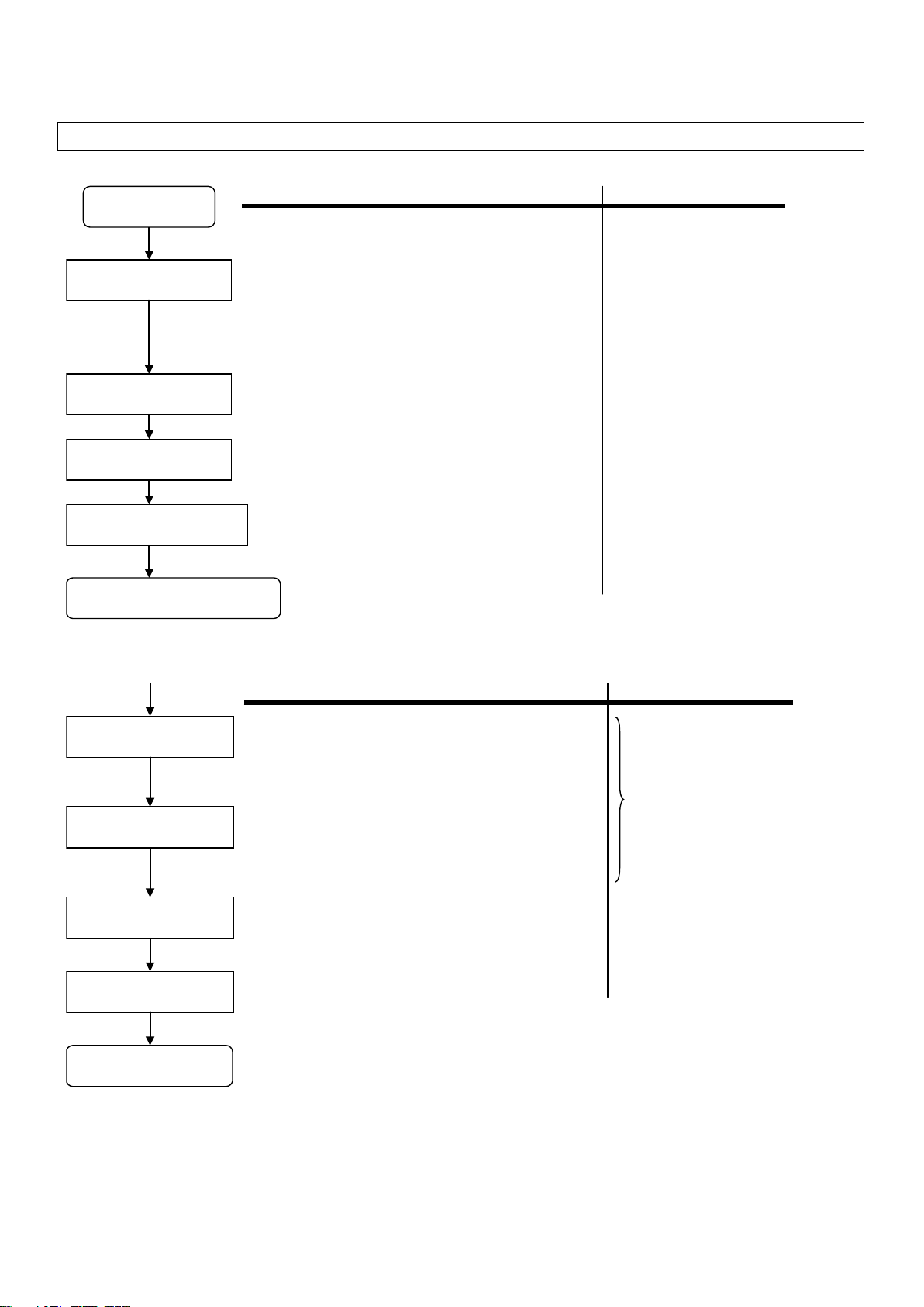
Follow the below work flow to replace C200HS with CJ2. Refer to the reference pages for details.
1. Work flow
Selecting the model
Reading PLC data
Description
Reference Pages
S
elect the
units, programming software, and connecting
cables to replace C200HS with CJ2.
The
C20
0H-series Units cannot be used with CJ2. Read the
reference pages (recommended models and
remarks) and
select the models.
Load the program, I/O Memory and other settings from the
C200HS using the programming software and connecting
cable.
Converting and modifying data
Convert the data read from C200H
S for CJ2.
Most of the data can be automatically converted; however,
some instructions and some Unit data can
not be converted.
Refer to the reference pages and modify the data and program
separately.
3. Selecting the model
4. Reading data from C200H
S
Preparing Units
P
repare the
units, programming software, and connecting
cables.
5. Converting
the program for
CJ2
Continue to actual replacement work
Start
Replacing Units
Writing
the data to CJ2
Description
Reference pages
Install the prepared Units instead of C200H-series Units.
*Refer to the SYSMAC CJ Series CJ2 CPU Unit Hardware
USER'S MANUAL (Cat. No. W472) and user's manuals for
Special I/O Unit s an d CPU Bus Unit s for details of installation.
Transfer the converted data to CJ2
To check the wiring, operate input and output bits to see if
they operate correctly.
Checking operation
Turn ON the power and check the operation.
Related Manuals
Wiring
Wiring for the installed Units.
*Refer to the SYSMAC CJ Series CJ2 CPU Unit Hardware
USER'S MANUAL (Cat. No. W472) and user's manuals for
Special I/O Units and CPU Bus Units for details of wiring.
6. Writing data to CJ2
Replacement
completion
1. If production is conducted between uploading the program and executing replacement
work, data handled by the program may change. If so, upload the data right before the
replacement work, modify data (if necessary), and download it to the new PLC.
2. The cycle time of C200HS and CJ2 are different, which may affect system operation. If
so, it is necessary to adjust cycle time in the PLC Setup.
1) Preliminary Steps: Take the following steps before starting the replacement work.
2) Actual replacement work: Take the following steps to replace C200HS with CJ2
2
Page 12

2. Selecting the replacement method
When C200H-series Basic I/O Units are replaced with CJ-series Basic I/O Units, rewiring is required. When
Replacement method
Description
CPU
CJ-series Units
CJ1W-ID231
Conversion Cable
XW2Z-S010
Connecting cable that was
connected to C200H-ID215
(reuse)
CJ1W-OD231
Conversion
Cable
XW2Z-S011
Connecting cable that was
connected to C200H-OD215
(reuse)
C200H-ID215 and C200H-OD215 C200H High-density I/O Units are replaced with CJ-s eries I/O Units, the same
connecting cables that were connected to C200H High-density I/O Units can be used.
Using Conversion Cables
for C200H High-density
I/O Units
Replace C200H-ID215 with CJ1W-ID231, and
connect CJ1W -I D231 using the same
connecting cables used f or C200H-I D215. In
the same way, replace C200H-OD215 with
CJ1W-OD231, and connect CJ1W-OD231
using the same cable us ed for C200H-OD215.
Pros: Rewiring of I/O Units i s not required,
which reduces replacement ti me.
3
Page 13

• Replacement of C200H-ID215 and C200H-OD215 using Conversion Cables
C200H-series Unit
CJ-series Unit
Conversion Cable
C200H-ID215
CJ1W-ID231
XW2Z-S010
C200H-OD215
CJ1W-OD231
XW2Z-S011
Make sure that the connected device operates
correctly.
Make sure that the connected device operates
correctly.
Make sure that the connected device operates
correctly.
2.5 ms max./15 ms max.
(switchable)
2.5 ms max./15 ms max.
(switchable)
8 points/common x
4 circuits (32 inputs)
16 points/common x
2 circuits (32 inputs)
The number of circuits decreased from 4 to 2.
Rewire if separate power supplies are used.
8 points (when pin 2 of the
DIP switch is ON)
* CN1 COM0 and COM1 and
power supply.
The same connecting c ables that were connected to C200H-ID215 and C200H-OD215 can be used to replace
them with CJ1W-ID231 and CJ1W-OD231.
XW2Z-S010
CN2 COM2 and COM3 are
internally connected in the
CJ1W-ID231 C200H-ID215
Reused cable
CJ-series Unit. When separate
power supplies were used,
rewire to use one common
C200H-ID215 CJ1W-ID231 Remarks
Rated input voltage 24 VDC 24 VDC
Operating input voltage 20.4 to 26.4 VDC 20.4 to 26.4 VDC
Input impedance 5.6 kΩ 5.6 kΩ
Input current 4.1 mA typical (at 24 VDC) 4.1 mA typical (at 24 VDC)
ON voltage 14.4 VDC min. 19 VDC min.
OFF voltage 5 VDC max. 5 VDC max.
ON response time
OFF response time
No. of circuits
High-speed inputs
4
8 ms max. (switchable) Can be set to between 0 and 32 ms in the PLC Setup.
8 ms max. (switchable) Can be set to between 0 and 32 ms in the PLC Setup.
Not supported Use CJ1W-IDP01 for high-speed inputs.
Page 14

XW2Z-S011
We recommend you to use 24 VDC instead if 5 VDC
is used.
16 mA/4.5 VDC to
3.2 A/Unit
Make sure that the connected device operates
correctly.
Make sure that the connected device operates
correctly.
Make sure that the connected device operates
correctly.
8 points/common x
4 circuits (32 outputs)
16 points/common x
2 circuits (32 outputs)
The number of circuits decreased from 4 to 2.
Rewire if separate power supplies are used.
When protection is required, connect a protective
device externally.
5 to 24 VDC±10%,
2.8 mA x no. of ON outputs
* CN1 COM0 and COM1 and
power supply.
CJ1W-OD231 C200H-OD215
Reused cable
CN2 COM2 and COM3 are
internally connected in the
CJ-series Unit. When separate
power supplies were used,
rewire to use one common
C200H-OD215 CJ1W-OD231 Remarks
Rated voltage 5 to 24 VDC 12 to 24 VDC
Max. switching capacity
Leakage current 0.1 mA max. 0.1 mA max.
Residual voltage 0.7 V max. 1.5 V max.
ON response time 0.2 ms max. 0.1 ms max.
OFF response time 0.6 ms max. 0.8 ms max.
No. of circuits
Fuses 4 (1 fuse/common) None
External power supply
Dynamic outputs 30 mA min. Not supported Dynamic outputs are not supported.
100 mA/26.4 VDC
0.8 A/common,
90 mA min.
0.5 A/point,
2 A/common, 4 A/Unit
10.2 to 26.4 VDC,
30 mA min.
5
Page 15

3. Selecting the model
Outline of the system configuration
C200HS
PC
Expansion Backplane
CJ2
PC
I/O Interface Unit
SYSMAC Support Software
CX-Programmer
CX-Programmer
Unit name
C200H-series Unit
CJ-series Unit
Description
CPU Unit
C200HS-CPU01(-C)
[CJ2H]
EtherNet/IP port.
CPU Unit-mounting
Host Link Unit
C200HS-CPU21/23/31/33
Serial port (RS-232C) built
in the CPU Unit.
Power Supply Unit
(For
C200HS-CPU01/01-C/21/31)
CJ1W-PA202
(AC Power Supply Unit)
To use RUN output, prepare an Output Unit
separately.
CJ1W-PA205C
(AC Power Supply Unit)
With replacement notification function.
CJ1W-PA205R
(AC Power Supply Unit)
With RUN output.
(For C200HS-CPU03/23/33)
CJ1W-PD022
non-insulated type)
To use RUN output, prepare an Output Unit
CJ1W-PD025
(DC Power Supply Unit)
To use RUN output, prepare an Output Unit
separately.
CPU Backplane
C200H-BC031(-□□)
Unnecessary
PFP-100N2
CJ-series Units are installed on the DIN
I/O Control Unit
Unnecessary
CJ1W-IC101
Required to connect a CJ-series E xpansion
Rack to a CJ-series CPU Rack.
The table below lists the C200H-series Units and each corresponding CJ-series Unit. Select the CJ-series Unit
which is compatible with the C200H-series Unit or which has similar specifications to the C200H-series Unit.
Refer to the CJ2H-CPU6□-EIP/CJ2H-CPU6□/CJ2M-CPU□□ SYSMAC CJ Series CJ2 CPU Unit Hardware USER'S
MANUAL (Cat. No. W472) for details of the Units.
< CPU Rack >
C200HS-CPU03
C200HS-CPU21
C200HS-CPU23
C200HS-CPU31
C200HS-CPU33
CJ2H-CPU64(-EIP)
CJ2H-CPU65(-EIP)
CJ2H-CPU66(-EIP)
CJ2H-CPU67(-EIP)
CJ2H-CPU68(-EIP)
[CJ2M]
CJ2M-CPU11/CPU31
CJ2M-CPU12/CPU32
CJ2M-CPU13/CPU33
CJ2M-CPU14/CPU34
CJ2M-CPU15/CPU35
(DC Power Supply Unit,
UM 50K steps
UM 100K steps
UM 150K steps
UM 250K steps
UM 400K steps
*The EIP models have one built-in
EtherNet/IP port.
UM 5K steps
UM 10K steps
UM 20K steps
UM 30K steps
UM 60K steps
*The CPU3□ models have one built-in
separately.
6
C200H-BC051(-□□)
C200H-BC081(-□□)
C200H-BC101(-□□)
[DIN Track]
PFP-50N
PFP-100N
Track. The CPU Backpl ane i s not required.
Page 16

< Memory Cassettes >
Unit name
C200H-series Unit
CJ-series Unit
Description
Memory Unit
EEPROM Unit
None
The CJ2-series CPU Unit has a nonvolatil e
at Startup)
EPROM Unit
None
The CJ2-series CPU Unit has a nonvolatil e
at Startup)
Unit name
C200H-series Unit
CJ-series Unit
Description
Power Supply Unit
C200H-PS221
CJ1W-PA202
(AC Power Supply Unit)
CJ1W-PA205C
(AC Power Supply Unit)
With replacement notification function.
CJ1W-PA205R
(AC Power Supply Unit)
The RUN output does not operate.
C200H-PS211
CJ1W-PD022
non-insulated type)
CJ1W-PD025
(DC Power Supply Unit)
Backplane
C200H-BC031(-□□)
Unnecessary
PFP-100N2
CJ-series Units are installed on the DIN
I/O Interface Unit
Unnecessary
CJ1W-II101
Required for each CJ-series Expansion
Rack.
I/O Connecting Cable
C200H-CN311 (0.3 m)
CS1W-CN313 (0.3 m)
CS1W-CN133-B2 (12 m)
Connects an I/O Control Unit to an I/O
< Expansion Rack >
C200HS-ME16K
C200HS-MP16K
memory for user program i n i t . The Memory
Unit is not required.
It also has the cloc k function.
The program file and the paramet ers are
stored in the memory c ard. It is possible to
execute operation by reading them when the
PLC is turned ON. (Automatic File Transfer
memory for user program i n i t . The Memory
Unit is not required.
It also has the cloc k function.
The program file and the paramet ers are
stored in the memory c ard. It is possible to
execute operation by reading them when the
PLC is turned ON. (Autom atic File Transfer
(DC Power Supply Unit,
(Expansion Backplane)
C200H-BC051(-□□)
C200H-BC081(-□□)
C200H-BC101(-□□)
C200H-CN711 (0.7 m)
C200H-CN221 (2 m)
C200H-CN521 (5 m)
C200H-CN131 (10 m)
[DIN Track]
PFP-50N
PFP-100N
CS1W-CN713 (0.7 m)
CS1W-CN223 (2 m)
CS1W-CN323 (3 m)
CS1W-CN523 (5 m)
CS1W-CN133 (10 m)
Track. The Backplane i s not required.
Interface Unit or connect s an I/O Interface
Unit to another I/O Interface Unit.
7
Page 17

< I/O Units and CPU Bus Units>
Unit name
C200H-series Unit
CJ-series Unit
Description
Basic I/O Unit
C200H-I□□□
CJ1W-I□□□
Refer to Appendix E. Table of Input/Output
Units.
Special I/O Unit
C200H-□□□□
CJ1W-□□□□
Select a required model to replace the
Special I/O Unit ins t ead.
Communication Unit
[SYSMAC LINK]
C200HW-SLK13/14
[SYSMAC LINK]
SYSMAC LINK cannot be used with the
[SYSMAC NET]
[SYSMAC NET]
SYSMAC NET cannot be used with the
Manual (Cat. No. W309) for details.
[Host Link]
[Serial Communic ations]
C200H-series Host Link Units c annot be
MANUAL (Cat. No. W336) for details.
C200H-LK101-PV1
None
(+ optical link modul e)
The CJ Series does not have an Optical-type
link module.
C200H-LK201-V1
CJ1W-SCU21-V1
CP1W-CIF01 is required.
Use one of the left CJ-series Units/Boards..
C200H-LK202-V1
CJ1W-SCU31-V1
CJ1W-SCU41-V1
Use one of the left CJ-series Units/Boards.
[PC Link]
[PC Link]
Optical: None
PC Link cannot be used with the CJ2-series
Manual (Cat. No. W309) for details.
[SYSMAC BUS]
[SYSMAC BUS]
SYSMAC BUS cannot be used with the
No. W266) for details of CompoBus/S.
C200H-O□□□
C200H-M□□□
Coaxial:
C200H-SLK21-V1
C200HS-SLK22
C200HW-SLK23/24
Optical:
C200H-SLK11
C200HS-SLK12
C200H-SNT31
C200HS-SNT32
CJ1W-O□□□
CJ1W-M□□□
None
[Controller Link]
Wired: CJ1W-CLK23
Optical: None
None
[Controller Link]
Wired: CJ1W-CLK23.
Optical: None
Units for CJ-series Basic I/O Units
corresponding to C200H-series Basic I/O
C200H-series Unit. Refer to the manuals of
Special I/O Units f or specifications.
When there is no CJ-series Special I/O Unit
which has the same funct i ons and
specifications as the C200H-series Unit, we
recommend you to use another CJ-series
CJ2-series CPU Unit.
We recommend you to use Controller Link
instead.
Refer to the Controller Link Units Operation
Manual (Cat. No. W309) for details.
CJ2-series CPU Unit.
We recommend you to use Controller Link
instead.
Refer to the Controller Link Units Operation
used with the CJ2-series CPU Uni t.
Refer to the SYSMAC CS/CJ Series Serial
Communications Boards/Units OPERATION
C200H-LK401
Wired: C200H-RM201
Optical: C200H-RM001-PV1
CJ1W-SCU21-V1
CJ1W-SCU41-V1
Host Link port built in the
CPU Unit
*For CJ2M-CPU3□,
None
[Controller Link]
Wired: CJ1W-CLK23.
None
[CompoNet]
CJ1W-CRM21
[DeviceNet]
CJ1W-DRM21
[CompoBus/S]
CJ1W-SRM21
Serial Communicat i ons Board/Unit. Use the
wired type instead or use an external optical
*CJ2M-CPU3□ does not have a built-in Host
Link port. Purchase the CP1W-CIF01
RS-232C Option Board.
CPU Unit.
We recommend you to use Controller Link
instead.
Refer to the Controller Link Units Operation
CJ2-series CPU Unit.
We recommend you to use left networks
instead.
Refer to the CS/CJ series CompoNet Master
Units OPERATION MANUAL (Cat. No.
W456) and CompoNet Slave Units and
Repeater Unit OPERATION MANUAL (Cat.
No. W457) for details of CompoNet.
Refer to the
CS1W-DRM21(-V1),CJ1W-DRM21 CS/CJ
SERIES DeviceNet UNITS OPERATION
MANUAL (Cat. No. W380) for details of
DeviceNet.
Refer to the
C200HW/CS1W/CJ1W/CQM1/SRT1/SRT2
CompoBus/S OPERATION MANUAL (Cat.
8
Page 18

< Support Software and Peripheral Devices >
Name
C200H-series Unit
CJ-series Unit
Description
Support Software
SYSMAC C-series Ladder
CX-Programmer
CX-One
SYSMAC Support Software cannot be us ed
Peripheral Interface
Unit, Connecting Cable
CQM1-CIF02
Commercially available
USB cable
USB 2.0 (or 1.1) cable
(A connector – B connector) 5.0 m max..
Programming Console
C200H-PRO27
(+C200HS-CN222 attached)
None
Use the CX-Programmer or Programming
Support Software
C500-SF610-V6 (5 inches)
C500-SF410-V6 (3.5 inches)
(+C200H-CN222/422)
(+C200HS-CN222/422)
CQM1-PRO01
CXONE-AL□□C-V□/
AL□□D-V□
(CX-Programmer)
with the CJ2-series CPU Unit.
Console function of the NS-series
Programmable Termi nal .
Other remarks
(1) The CJ2-series CPU Unit is separated fr om the Power Supply Unit although the C200HS-series CPU Unit
is combined with the Power Supply Unit.
(2) The PFP-50N/100N/100N2 DIN Track and C200H-DIN01 Mounting Bracket can be used to install the
CJ-series Units on the DIN Track.
(3) The CJ-series Unit has an installation structure to be insulated f rom the control panel (DIN Track). T he
C200H-ATT31/51/81/A1 Insulation Plate for CPU Backplane is not required.
9
Page 19

4. Reading data from C200HS
Load the ladder program, PLC settings, and Data Memory from C200HS using the CX-Programmer.
Required items
Support Software
CX-One
CX-Programmer (WS02-CXPC□-V□)
Connecting Cable
CQM1-CIF02
C200HS
PC
CX-Programmer
Connecting Cable
CQM1-CIF02
Connector for programming device
(PC)
(CXONE-AL□□C-V□, CXONE-AL□□D-V□)
or
(1) Connect C200HS and a PC using a connecting cable.
(2) Start up the CX-Programmer. (Select All Program - OMRON - CX-One - CX-Programmer - CX-Programmer
from the Windows Start Menu.)
(3) Select C200HS for the Device Type. (Select New from the File Menu to display the below dialog box.)
10
Page 20

(4) Select Work Online from the PLC Menu to go online.
(5) Transfer the ladder program and I/O table. (Select Transfer - From PLC from the PLC Menu.)
Click the OK Button to start transfer.
(6) Transfer the PLC memory data (Data Memory). (Select Edit - Memory from the PLC Menu.)
Scroll and select all the areas. Click the Transfer from PLC Button to start transfer.
(7) Select Work Online from the PLC Menu to go offline.
(8) Save the program with a new project name. (Select Save As from the File Menu.)
11
Page 21

5. Converting the program for CJ2
On the CX-Programmer, convert the program for CJ2.
(1) Start the CX-Programmer and open the saved program file for C200HS. (Select Open from the File Menu.)
(2) Change the Device Type from C200HS to CJ2M or CJ2H. (Select Change Model from the PLC Menu to
display the below dialog box.)
(3) The instructions are automatically converted. The Output Window shows the conversion results. Double-click
an error shown on the Output Window to jump to the corresponding section of the ladder program.
Errors and warnings at conversion will be displayed.
Double-click an error or a warning to jump to the corresponding circuit.
Some instructions cannot be converted. Modify the ladder program by referring to Appendix A. Instructions
converted by Change Model on CX-Programmer.
You can check the program by selecting Compile from the Program Menu. The Output Window shows the
checking results.
12
Page 22

(4) The PLC memory data cannot be maintained when the PLC model is changed. Open the PLC Memory Window
for both C200HS and CJ2, and copy and paste the necessary memory data.
Select the necessary PLC Memory on the C200HS PLC Memory Window, and
copy and paste it onto the CJ2 PLC Memory Window.
(5) The I/O allocation of C200HS is partly different from that of CJ2. Refer to Appendix B. Change of unit area
allocation and modify the ladder program.
(6) The PLC settings of C200HS are partly different from those of CJ2. Refer to Appendix C. Change in PLC
settings and change the PLC settings.
(7) Select Compile from the Program Menu to check the program. If an error is detected, correct it.
(8) Save the program with a new project name. (Select Save As from the File Menu.)
13
Page 23

6. Writing data to CJ2
Transfer the converted and modified program, PLC settings, and Data Memory to CJ2.
Required items
Support Software
CX-One
(CX-Programmer)
Connecting cable
Commercially available US B cable
(A connector – B connect or) 5. 0 m max.
CJ2
PC
CX-
Programmer
Connecting cable
Commercially available USB c abl e
P
eripheral (USB) port on
CPU Unit.
(PC)
CXONE-AL□□C-V□/ AL□□D-V□
USB 2.0 (or 1.1) cable
(1) Connect CJ2 with a PC.
(2) Start the CX-Programmer and open the converted program file for CJ2.
(3) Go online with CJ2.
(4) Transfer the ladder program and PLC settings to CJ2. (Select Transfer - To PLC from the PLC Menu.)
Select the Program(s) and Settings Check Boxes. Click the OK Button to start transfer.
14
Page 24

(5) Select Edit - Memory from the PLC Menu to display the below dialog box. Select the PLC memory (Data
Memory Area: D and Holding Area: HR) and click the Transfer to PLC Button to start transfer.
(6) Select Work Online from the PLC Menu to go offline.
15
Page 25

7. Appendix
Appendix A. Instructions converted by Change Model on CX-Programmer.
Instruction for C200HS
Instruction for CJ2
Operand
Number of operands
JMP(04)
JMP(004) or
When #0 is set t o the operand, JMP is converted to
If a value other than #0 is set, the operand is the same.
#0: Changed from 1 to 0
JME(05)
JME(005) or
When #0 is set t o the operand, JME is converted to
If a value other than #0 is set, the operand is the same.
#0: Changed from 1 to 0
WSFT(16)
Same as C200HS
#0 is added to the first operand.
WSFT St E → WS FT #0 St E
Changed from 2 to 3
FUN17
ASFT(017)
Same as C200HS
Same
XFER(70)
XFERC(565)
Same as C200HS
Same
MOVB(82)
MOVBC(568)
Same as C200HS
Same
DIST(80)
DISTC(566)
Same as C200HS
Same
COLL(81)
COLLC(567)
Same as C200HS
Same
FUN60
CMPL(060)
Same as C200HS
Same
FUN19
MCMP(019)
Same as C200HS
Same
FUN63
LINE(063)
Changed from BCD data to binary data.
Same
FUN64
COLM(064)
Changed from BCD data to binary data.
Same
FUN65
SEC(065)
Same as C200HS
Same
FUN66
HMS(066)
Same as C200HS
Same
INC(38)
++B(594)
Same as C200HS
Same
DEC(39)
--B(596)
Same as C200HS
Same
ADD(30)
+B(404)
Same as C200HS
Same
ADDL(54)
+BL(405)
Same as C200HS
Same
SUB(31)
-B(414)
Same as C200HS
Same
SUBL(55)
-BL(415)
Same as C200HS
Same
MUL(32)
*B(424)
Same as C200HS
Same
MULL(56)
*BL(425)
Same as C200HS
Same
DIV(33)
/B(434)
Same as C200HS
Same
DIVL(57)
/BL(435)
Same as C200HS
Same
ADB(50)
+(400)
Same as C200HS
Same
SBB(51)
-(410)
Same as C200HS
Same
MLB(52)
*(420)
Same as C200HS
Same
DVB(53)
/(430)
Same as C200HS
Same
FUN69
APR(069)
Same as C200HS
Same
FUN89
Not supported
Combine and use the following inst ructions: MSKS(690), CLI(691), MSKR(692),
DI(693), EI(694)
STEP(08)
Same as C200HS
The CIO, Holding, Work, Auxiliary, Link Areas are all
converted into the W ork Area.
Same
SNXT(09)
Same as C200HS
instruction.
Same as C200H
Same
FAL(06)
Same as C200HS
#0 is added to the second operand.
FAL N FAL N #0
Changed from 1 to 2.
FALS(07)
Same as C200HS
#0 is added to the second operand.
FALS N FALS N #0
Changed from 1 to 2.
MSG(46)
MSG(046)
#0 is added to the first operand.
characters (8 words) to 32 characters (16 words).
Changed from 1 to 2.
FUN47
Not supported
Use MSG(046) instead.
―
FUN67
BCNTC(621)
Same as C200HS
Same
WDT(94)
WDT(094)
Control data configuration is changed.
Same
FUN61
Not supported
Use IORF (097) instead.
FUN18
Enter the settings in the PLC Setup.
FUN48
Not supported
― ― FUN49
Enter the settings in the PLC Setup.
FUN90
SEND(090)
Control data configuration is changed.
Same
FUN98
RECV(098)
Control data configuration is changed.
Same
(1) The data type of operand is changed from BCD to binary for some instructions.
(2) The number of operands is changed for some instructions.
(3) Interrupt control instructions must be changed. (Use MSKS, MSKR, CLI, DI, and EI).
Refer to the list below for details. The table lists the instructions which differ between before and after conversion. The other
instructions remain unchanged after conversion.
JMP0(515)
JME0(516)
JMP0 and the operand is deleted.
JME0 and the operand is deleted.
<> #0: Same
<> #0: Same
Use a differentiated
execution condition
for the SNXT
MSG FM MSG #0 M
The number of characters (words) to be regi stered
from the first message word is changed from 16
16
Page 26

Instruction for C200HS
Instruction for CJ2
Operand
Number of operands
NEG(--)
NEG(160)
Same as C200HS
However, if NEG Flag UF (25405) is used, change the
Condition flags to P_N (Negative Flag).
Same
NEGL(--)
NEGL(161)
Same as C200HS
Condition flags to P_N (Negative Flag).
Same
However, if NEGL Flag UF (25405) is used, change the
17
Page 27

Appendix B. Change of unit area allocation
Item
C200HS
CJ2
Description
I/O allocation
"Free location and fixed word allocation"
"Free location and free word allocation"
used in the program.
I/O allocation
IR 100 to IR 199
CIO 2000 to CIO 2199
Refer to the
details on I/O allocation.
I/O allocation
IR 030 to IR 049
The allocation is decided i n t he same
used in the program.
Special Relay Area
SR 236 to SR 255
(1) Auxiliary Area and bits
"P_1ms".
In CJ2, operation flags and
PLC Link Words
SR 247 to SR 250
(in SR Area)
None
PC Link cannot be used with
CJ2.
Link Relay Area
(LR)
LR 00 to LR 63
None
PC Link cannot be used with
CJ2.
SYSMAC BUS Area
IR 050 to IR 099
None
SYSMAC BUS cannot be used
with CJ2.
Optical I/O Unit and
I/O Terminal Area
IR 200 to IR 231
None
The Optical I/O Unit cannot be
used with CJ2.
Error Log Area
DM 6000 to DM 6030
A100 to A199
Change the program if the
program.
Temporary Relay Area
(TR)
TR 00 to TR 07
TR 00 to TR 15
Holding Relay Area
(HR)
HR 00 to HR 99
H 000 to H 511
Work Area (WR)
IR 030 to IR 235
CIO 1200 to CIO 1499
W000 to W511
Item
C200HS
CJ2
Description
PLC Setup
Always uses the DM Area (DM 6600
Uses dedicated area for PLC Setup
users).
Refer to related manuals for
Item
C200HS
CJ2
Description
Interrupt execution
Write interrupt programs in subroutines.
Write interrupt programs in interrupt
In CJ2, interrupt tasks are
or I/O is being refreshed.
Cycle time
-
The cycle time is shortened with CJ2.
conversion.
To keep the same cycl e t i me
Read Protection
function
FUN49
Use password protection functi on of the
CX-Programmer.
This section describes the differences in unit area allocation between C200HS and CJ2. Refer to related manuals for details.
Basic I/O
Special I/O
Group-2
High-density I/O
(SR)
Auxiliary Relay Area
(AR)
(10 words allocated for each Unit No.)
DM 1000 to DM 1999
(100 words allocated for each Unit No.)
(2 or 4 words allocated for each I/O
word)
SR 256 to SR 299
AR 00 to AR 27
Change the word and bit addresses
(10 words allocated for each Unit No.)
D20000 to D21999
(100 words allocated for each Unit No.)
Change the word and bit addresses
used in the program.
way as Basic I/O Units depending on
the installed position (rack and slot).
Change the word and bit addresses
Change the word and bit addresses
used in the program.
(2) Condition flags and clock pul ses
Change the arithmetic fl ags in the
program to the condition fl ags. Clock
pulses are specified us i ng gl obal
symbols, such as "P_0.1ms" and
CJ2H-CPU6□-EIP/CJ2H-CPU
6□/CJ2M-CPU□□ SYSMAC CJ
SERIES CJ2 CPU UNIT
SOFTWARE USER'S
MANUAL (Cat. No. W473) for
condition flags are speci fied by
labels.
IR 300 to IR 511
CIO 3800 to CIO 6143
Error Log Area is read in the
Appendix C. Change in PLC Settings
Functions which can be configured in the PLC Setup differ between C200HS and CJ2.
Although the DM Area (DM 6600 to DM 6655) is allocated for the PLC Setup in C200HS, CJ2 does not use the DM Area for the
PLC Setup; the settings are changed from the CX-Programmer or a Programming Console.
to DM 6655).
(there is no address for sett i ng by
details.
Appendix D. Change of execution timing etc.
method and execution
timing
tasks.
If the system operation is aff ected by
cycle time, c heck the operation after
executed even when an
instruction is being executed
as C200HS, set Minimum
Cycle Time in the PLC Set up.
18
Page 28

Appendix E. Table of Input/Output Units
C200H -series Unit
Corresponding CJ-series Unit
Description
Difference
C200H-ID211
CJ1W-ID211
DC Input Unit with terminal
1) Terminal block
(5 VDC: 10 mA → 80 mA)
12 to 24 VDC, 10 mA, Terminal
24 VDC, 7 mA, Termi nal bl ock,
C200H-ID212
CJ1W-ID211
DC Input Unit with terminal
1) Terminal block
(5 VDC: 10 mA → 80 mA)
24 VDC, 7 mA, Termi nal bl ock,
24 VDC, 7 mA, Termi nal bl ock,
C200H-ID215
CJ1W-ID231
DC Input Unit with connector
1) Connector
(5 VDC: 130 mA → 90 mA)
24 VDC, 4.1 mA, Connect or,
24 VDC, 4.1 mA,
C200H-ID216
CJ1W-ID231
DC Input Unit with connector
1) No. of circuits (32 points/common x 1 circuit
(5 VDC: 100 mA → 90 mA)
24 VDC, 4.1 mA, Connect or,
24 VDC, 4.1 mA,
C200H-ID218
CJ1W-ID231
DC Input Unit with connector
1) No. of circuits (32 points/c ommon x 1 circuit
(5 VDC: 100 mA → 90 mA)
24 VDC, 6 mA, Connector,
24 VDC, 4.1 mA,
C200H-ID111
CJ1W-ID261
DC Input Unit with connector
1) No. of circuits (32 points/common x 2 circuits
(5 VDC: 120 mA → 90 mA)
12 VDC, 4.1 mA, Connect or,
24 VDC, 4.1 mA,
C200H-ID217
CJ1W-ID261
DC Input Unit with connector
1) No. of circuits (32 points/common x 2 circuits
(5 VDC: 120 mA → 90 mA)
24 VDC, 4.1 mA, Connect or,
24 VDC, 4.1 mA,
C200H-ID219
CJ1W-ID261
DC Input Unit with connector
1) No. of circuits (32 points/common x 2 circuits
(5 VDC: 120 mA → 90 mA)
24 VDC, 6 mA, Connector,
24 VDC, 4.1 mA,
■ Input Unit
(1) The terminal block of the CJ-series Unit differs from that of the C200H-series Unit. Change the wiring.
(2) If a different type of connector is used, change the wiring.
(3) If the input specifications differ, make sure that the system operates correctly.
(4) If the number of circuits increases, rewire the terminals to each common terminal.
(5) If internal current consumption is different, make sure the power supply capacity is large enough.
(6) Refer to the related manuals f or details. Although CJ -s er ies Units have basic f unc tions of C200H-series Units,
some specifications may differ.
< DC Input Units >
block, 8 inputs
16 inputs
32 inputs (Special I/O)
32 inputs (Group-2)
32 inputs (Group-2)
16 inputs
16 inputs
Connector, 32 inputs
Connector, 32 inputs
Connector, 32 inputs
block for 8 inputs.
Replace this unit with a DC
Input Unit with 16 inputs.
block for 16 inputs.
for 32 inputs.
for 32 inputs.
for 32 inputs.
2) Input points (8 points → 16 points)
3) Input circuit spec i f i cations
Input impedance (2 kΩ → 3.3 kΩ)
ON voltage (10.2 VDC → 14.4 VDC)
OFF voltage (3 VDC → 5 VDC)
4) Internal current consum ption
2) Input circuit speci fication
Input impedance (3 kΩ → 3.3 kΩ)
3) Internal current consum pt i on
Use the XW2Z-S010 Conversion Cable to
reuse the connecting cable.
2) No. of circuits (8 points/common x 4 circuits
→ 16 points/common x 2 circuits)
3) Input circuit spec i f i cation
ON voltage(14.4 VDC → 19 VDC)
4) Internal current consum ption
→ 16 points/common x 2 circuits)
2) Input circuit spec i f i cation
ON voltage (14.4 VDC → 15.4 VDC)
3) Internal current consum ption
→ 16 points/common x 2 circuits)
2) Internal current consum ption
64 inputs (Group-2)
64 inputs (Group-2)
64 inputs (Group-2)
Connector, 64 inputs
Connector, 64 inputs
Connector, 64 inputs
for 64 inputs.
for 64 inputs.
for 64 inputs.
→ 16 points/common x 4 circuits)
2) Input circuit spec i f i cations
Input voltage (12 VDC → 24 VDC)
Input impedance (2.7 kΩ → 5.6 kΩ)
ON voltage (8 VDC → 19 VDC)
OFF voltage (3 VDC → 5 VDC)
3) Internal current consum ption
→ 16 points/common x 4 circuits)
2) Input circuit spec i f i cation
ON voltage (14.4 VDC → 19 VDC)
3) Internal current consum ption
→ 16 points/common x 4 circuits)
2) Input circuit specifications
Input impedance (3.9 kΩ → 5.6 kΩ)
ON voltage (15.4 VDC → 19 VDC)
3) Internal current consumption
19
Page 29

< TTL Input Unit >
C200H-series Unit
Corresponding CJ-series Unit
Description
Difference
C200H-ID501
TTL Input Unit with connector f or 32 inputs. The CJ Series does not have the
5 VDC, 3.5 mA, Connect or,
32 inputs (Special I/O)
C200H-series Unit
Corresponding CJ-series Unit
Description
Difference
C200H-IA121
CJ1W-IA111
100 VAC Input Unit with
1) Terminal block
(5 VDC: 10 mA → 90 mA)
100 to 120 VAC, 10 mA,
100 to 120 VAC, 7 mA,
C200H-IA221
CJ1W-IA201
200 VAC Input Unit with
1) Terminal block
(5 VDC: 10 mA → 80 mA)
200 to 240 VAC, 10 mA,
200 to 240 VAC, 9 mA,
C200H-IA122/IA122V
CJ1W-IA111
100 VAC Input Unit with
1) Terminal block
(5 VDC: 10 mA → 90 mA)
100 to 120 VAC, 10 mA,
100 to 120 VAC, 7 mA,
C200H-IA222/IA222V
CJ1W-IA201
200 VAC Input Unit with
1) Terminal block
(5 VDC: 10 mA → 80 mA x 2)
200 to 240 VAC, 10 mA,
Directive
200 to 240 VAC, 9 mA,
C200H-series Unit
Corresponding CJ-series Unit
Description
Difference
C200H-IM211
CJ1W-ID211
AC/DC Input Unit with
1) Terminal block
(5 VDC: 10 mA → 80 mA)
12 to 24 VAC/VDC ,
24 VDC, 7 mA, Terminal block,
C200H-IM212
CJ1W-ID211
AC/DC Input Unit with
inputs.
1) Terminal block
24 VAC/VDC , Terminal bl oc k,
24 VDC, 7 mA, Terminal block,
< AC Input Units >
Terminal block, 8 inputs
Terminal block, 8 inputs
Terminal block, 16 inputs,
IA122V: Complying with EC
Directive
Terminal block, 16 inputs,
IA222V: Complying with EC
No replacement model
Terminal block, 16 inputs
Terminal block, 8 inputs
Terminal block, 16 inputs
Terminal block, 8 inputs
same type of Unit.
Use the CJ1W-ID231 24-VDC Input Unit or CJ1W-MD563 TTL I/O Unit instead.
terminal block for 8 i nputs.
Replace this unit with a 100
VAC Input Unit with 16 inputs.
terminal block for 8 i nputs.
.
terminal block for 16 i nputs.
terminal block for 16 i nputs.
Replace this unit with two
200 VAC Input Units with 8
inputs.
2) Input points (8 points → 16 points)
3) Input circuit spec i f i cations
Input impedance (9.7 kΩ → 14.5 kΩ)
ON voltage (60 VAC → 70 VAC)
4) Internal current consum ption
2) Input points (8 points → 8 points*)
*16 I/O bits (1 word) are allocated.
3) Internal current consum ption
2) Input circuit speci fications
Input impedance (9.7 kΩ → 14.5 kΩ)
ON voltage (60 VAC → 70 VAC)
3) Internal current consum pt i on
2) No. of circuits (16 points/common x 1 circuit
→ 8 points/common x 1 circuit x 2)
3) Internal current consum ption
< AC/DC Input Units >
Terminal block, 8 inputs
16 inputs
16 inputs
16 inputs
terminal block for 8 i nputs.
Replace this unit with a DC
Input Unit with 16 inputs.
*The CJ Series does not have
an AC/DC Input Unit. If this
Unit is used with AC inputs,
change the wiring for DC
inputs.
terminal block for 16 inputs.
Replace this unit with a DC
Input Unit with 16 inputs.
*The CJ Series does not have
an AC/DC Input Unit. If this
Unit is used with AC inputs,
change the wiring for DC
2) Input points (8 points → 16 points)
3) Input circuit spec i f i cations
Input voltage range
(12 to 24 VAC/VDC → 24 VDC)
Input impedance (2 kΩ → 3.3 kΩ)
ON voltage (10.2 VDC → 14.4 VDC)
OFF voltage (3 VDC → 5 VDC)
4) Internal current consum ption
2) No. of circuits (16 points/common x 1 circuit
→ 8 points/common x 2 circuits)
3) Input circuit spec i f i cations
Input voltage range (24 VAC/VDC → 24 VDC)
Input impedance (3 kΩ → 3.3 kΩ)
4) Internal power consumption
(5 VDC: 10 mA → 80 mA)
20
Page 30

■ Output Unit
C200H-series Unit
Corresponding CJ-series Unit
Description
Difference
C200H-OC223
CJ1W-OC201
Relay Output Unit with
1) Terminal block
26 VDC: 46 mA → 24 VDC: 48 mA)
250 VAC/24 VDC, 2 A,
250 VAC/24 VDC, 2 A,
C200H-OC224
CJ1W-OC201
Relay Output Unit with
1) Terminal block
26 VDC: 75 mA → 24 VDC: 48 mA)
250 VAC/24 VDC, 2 A,
250 VAC/24 VDC, 2 A,
C200H-OC224V, OC224N
CJ1W-OC201
Relay Output Unit with
1) Terminal block
26 VDC: 90 mA → 24 VDC: 48 mA)
250 VAC/24 VDC, 2 A,
250 VAC/24 VDC, 2 A,
C200H-OC221
CJ1W-OC211
Relay Output Unit with
1) Terminal block
26 VDC: 75 mA → 24 VDC: 96 mA)
250 VAC/24 VDC, 2 A,
250 VAC/24 VDC, 2 A,
C200H-OC222
CJ1W-OC211
Relay Output Unit with
1) Terminal block
26 VDC: 75 mA → 24 VDC: 96 mA)
250 VAC/24 VDC, 2 A,
250 VAC/24 VDC, 2 A,
C200H-OC222V, OC222N
CJ1W-OC211
Relay Output Unit with
1) Terminal block
26 VDC: 90 mA → 24 VDC: 96 mA)
250 VAC/24 VDC, 2 A,
250 VAC/24 VDC, 2 A,
(1) The terminal block of the CJ-series Unit differs from that of the C200H-series Unit. Change the wiring.
(2) If a different type of connector is used, change the wiring.
(3) If the number of circuits increases, rewire the terminals to each common terminal.
(4) If the output specifications differ, make sure that the system operates correctly.
(5) The relay lifetime may vary depending on usage when a diff er ent relay is used. Refer to A-1-3 Precautions on
Contact Output Unit of the CJ2H-CPU6□-EIP/CJ2H-CPU6□/CJ2M-CPU□□ SYSMAC CJ Series CJ2 CPU Unit
Hardware USER'S MANUAL (Cat. No. W472) for details.
(6) If internal current consumption is different, make sure the power supply capacity is large enough.
(7) If the voltage and current consumption of the external power supply differ, make sure the power supply
capacity is large enough.
(8) Refer to the related manuals f or details. Although CJ -s er ies Units have basic f unc tions of C 200H-series Units,
some specifications may differ.
< Relay Output Units >
Terminal block, 5 out puts
(independent contacts)
Terminal block, 8 out puts
(independent contacts)
Terminal block, 8 out puts
(independent contacts)
Terminal block, 8 out puts
Terminal block, 12 out puts
Terminal block, 8 out puts
(independent contacts)
Terminal block, 8 out puts
(independent contacts)
Terminal block, 8 out puts
(independent contacts)
Terminal block, 16 out puts
Terminal block, 16 out puts
terminal block for 5 outputs
(independent contacts).
Replace this unit with a Relay
Output Unit with 8 outputs
(independent contacts).
terminal block for 8 outputs
(independent contacts).
terminal block for 8 outputs
(independent contacts).
terminal block for 8 outputs.
Replace this unit with a Relay
Output Unit with 16 outputs.
terminal block for 12 outputs.
Replace this unit with a Relay
Output Unit with 16 outputs.
2) Output points
(independent contacts 5 point s → 8 points)
3) Output circuit spec i fications
ON/OFF response time (10 ms → 15 ms)
Used relay
4) Internal current consum ption
(5 VDC: 10 mA → 90 mA,
2) Output circuit specifications
ON/OFF response time (10 ms → 15 ms)
Used relay
3) Internal current consum ption
(5 VDC: 10 mA → 90 mA,
2) Output circuit spec i fication
Used relay
3) Internal current consum ption
(5 VDC: 10 mA → 90 mA,
2) Output points (8 points → 16 points)
3) Output circuit spec i fications
ON/OFF response time (10 ms → 15 ms)
Used relay
4) Internal current consum ption
(5 VDC: 10 mA → 110 mA,
2) Output points (12 points → 16 points)
3) No. of circuits (12 points/common x 1 circuit
→ 8 points/common x 2 circuits)
4) Output circuit spec i fications
ON/OFF response time (10 ms → 15 ms)
Used relay
5) Internal current consum ption
(5 VDC: 10 mA → 110 mA,
Terminal block, 12 outputs
Terminal block, 16 out puts
terminal block for 12 outputs.
Replace this unit with a Relay
Output Unit with 16 outputs.
2) Output points (12 points → 16 points)
3) No. of circuits (12 points/common x 1 circuit
→ 8 points/common x 2 circuits)
4) Output circuit spec i fication
Used relay
5) Internal current consum ption
(5 VDC: 10 mA → 110 mA,
21
Page 31

< Relay Output Units >
C200H-series Unit
Corresponding CJ-series Unit
Description
Difference
C200H-OC225
CJ1W-OC211
Relay Output Unit with
1) Terminal block
26 VDC: 75 mA → 24 VDC: 96 mA)
250 VAC/24 VDC, 2 A,
250 VAC/24 VDC, 2 A,
C200H-OC226, OC226N
CJ1W-OC211
Relay Output Unit with
1) Terminal block
26 VDC: 90 mA → 24 VDC: 96 mA)
250 VAC/24 VDC, 2 A,
250 VAC/24 VDC, 2 A,
C200H-series Unit
Corresponding CJ-series Unit
Description
Difference
C200H-OD411
CJ1W-OD211
Transistor Output Unit with
1) Terminal block
(5 VDC: 140 mA → 100 mA)
12 to 48 VDC, 1 A, Sinking,
12 to 24 VDC, 0.5 A, Sinki ng,
C200H-OD213
CJ1W-OD211
Transistor Output Unit with
1) Terminal block
(5 VDC: 140 mA → 100 mA)
24 VDC, 2.1 A, Sinking,
12 to 24 VDC, 0.5 A, Sinki ng,
C200H-OD214
CJ1W-OD212
Transistor Output Unit with
1) Terminal block
0.5 A/point, 5 A/Unit )
(5 VDC: 140 mA → 100 mA)
24 VDC, 0.8 A, Sourcing,
24 VDC, 0.5 A, Sourcing,
C200H-OD216
CJ1W-OD212
Transistor Output Unit with
1) Terminal block
(Not required → 24 VDC/40 mA)
5 to 24 VDC, 0.3 A, Sourcing,
24 VDC, 0.5 A, Sourcing,
C200H-OD211
CJ1W-OD211
Transistor Output Unit with
1) Terminal block
(5 VDC: 160 mA → 100 mA)
24 VDC, 0.3 A, Sinking,
12 to 24 VDC, 0.5 A, Sinki ng,
Terminal block, 16 out puts
Terminal block, 16 out puts
< Transistor Output Units >
Terminal block, 8 out puts
Terminal block, 16 out puts
Terminal block, 16 out puts
Terminal block, 16 out puts
terminal block for 16 outputs.
terminal block for 16 outputs.
terminal block for 8 outputs.
Replace this unit with a
Transistor Output Unit with 16
outputs.
2) No. of circuits (16 points/common x 1 circuit
→ 8 points/common x 2 circuits)
3) Output circuit spec i fications
ON/OFF response time (10 ms → 15 ms)
Used relay
4) Internal current consum ption
(5 VDC: 10 mA → 110 mA,
2) No. of circuits (16 points/common x 1 circuit
→ 8 points/common x 2 circuits)
3) Output circuit specification
Used relay
4) Internal current consum ption
(5 VDC: 10 mA → 110 mA,
2) Output points (8 points → 16 points)
3) Output circuit spec i fications
Voltage range (12 to 48 VDC → 12 to 24VDC)
Output capacity
(1 A/point, 3 A/Unit → 0.5 A/point, 5 A/Unit)
Residual voltage (1.4 V → 1.5 V)
ON response time (0.2 ms → 0.1 ms)
OFF response time (0.3 ms → 0.8 ms)
4) Internal current consumption
Terminal block, 8 out puts
Terminal block, Load s hort
circuit protection, 8 outputs
Terminal block, 8 out puts
Terminal block, 12 out puts
Terminal block, 16 out puts
Terminal block, Load short
circuit protection, 16 outputs
Terminal block, Load s hort
circuit protection, 16 outputs
Terminal block, 16 out puts
terminal block for 8 outputs.
Replace this unit with a
Transistor Output Unit with 16
outputs.
terminal block for 8 outputs.
Replace this unit with a
Transistor Output Unit with 16
outputs.
terminal block for 8 outputs.
Replace this unit with a
Transistor Output Unit with 16
outputs.
terminal block for 12 outputs.
Replace this unit with a
Transistor Output Unit with 16
outputs.
2) Output points (8 points → 16 points)
3) Output circuit spec i fications
Output capacity
(2.1 A/point, 5.2 A/Uni t → 0.5 A/point, 5 A/Unit)
Residual voltage (1.4 V → 1.5 V)
ON response time (0.2 m s → 0.1 ms)
OFF response time (0.3 ms → 0.8 ms)
4) Internal current consum ption
2) Output points (8 points → 16 points)
3) Output circuit spec i fications
Output capacity
(0. 8A/point, 2.4 A/Uni t →
ON response time (1 ms → 0.5 ms)
4) Internal current consum ption
2) Output points (8 points → 16 points)
3) Output circuit specifications
Output voltage range (5 to 24 VDC → 24 VDC)
ON response time (1.5 ms → 0.5 ms)
OFF response time (2 ms → 1 ms)
4) Internal current consumption (5 VDC: 10 mA
→ 100 mA, 26 VDC: 75 mA → 0 mA)
5) External power supply
2) Output points (12 points → 16 points)
3) Output circuit speci fications
Residual voltage (1.4 V → 1.5 V)
ON response time (0.2 ms → 0.1 ms)
OFF response time (0.3 ms → 0.8 ms)
4) Internal current consumption
22
Page 32

< Transistor Output Units >
C200H-series Unit
Corresponding CJ-series Unit
Description
Difference
C200H-OD217
CJ1W-OD212
Transistor Output Unit with
1) Terminal block
(Not required → 24 VDC: 40 mA)
5 to 24 VDC, 0.3 A, Sourcing,
24 VDC, 0.5 A, Sourcing,
C200H-OD212
CJ1W-OD211
Transistor Output Unit with
1) Terminal block
(5 VDC: 180 mA → 100 mA,)
24 VDC, 0.3 A, Sinking,
12 to 24 VDC, 0.5 A, Sinki ng,
C200H-OD21A
CJ1W-OD212
Transistor Output Unit with
1) Terminal block
5) Alarm output (Supported → Not supported)
24 VDC, 1.0 A, Sourcing,
24 VDC, 0.5 A, Sourcing,
C200H-OD218
CJ1W-OD231
Transistor Output Unit with
1) No. of circuits (32 points/common x 1 circuit
(5 VDC: 180 mA → 140 mA)
4.5 to 26.3 VDC, 0.1A, Si nking,
12 to 24 VDC, 0.5A, Sinki ng,
C200H-OD215
CJ1W-OD231
Transistor Output Unit with
1) Connector
(5 VDC: 220 mA → 140 mA)
4.5 to 26.3 VDC, 0.1 A, Si nking,
12 to 24 VDC, 0.5A, Sinki ng,
C200H-OD21B
CJ1W-OD232
Transistor Output Unit with
1) No. of circuits (32 points/common x 1 circuit
(5 VDC: 180 mA → 150 mA)
24 VDC, 0.5 A, Sourcing,
24 VDC, 0.5 A, Sourcing,
C200H-OD219
CJ1W-OD261
Transistor Output Unit with
1) No. of circuits (32 points/common x 2 circuits
(5 VDC: 270 mA → 170 mA)
4.5 to 26.3 VDC, 0.1 A, Si nking,
12 to 24 VDC, 0.3 A, Sinki ng,
Terminal block, 12 out puts
Terminal block, 16 out puts
Terminal block, Load s hort
circuit protection, 16 outputs
Connector, 32 outputs
(Group-2)
Terminal block, Load s hort
circuit protection, 16 outputs
Terminal block, 16 out puts
Terminal block, Load s hort
circuit protection, 16 outputs
Connector, 32 outputs
terminal block for 12 outputs.
Replace this unit with a
Transistor Output Unit with 16
outputs.
terminal block for 16 outputs.
terminal block for 16 outputs.
connector for 32 outputs.
2) Output points (12 points → 16 poi nt s)
3) Output circuit speci fications
Output voltage range (5 to 24 VDC → 24 VDC)
ON response time (1.5 ms → 0.5 ms)
OFF response time (0.5 ms → 1.0 ms)
4) Internal current consum pt i on
(5 VDC: 10 mA → 100 mA,
26 VDC: 75 mA → 0 mA)
5) External power supply
2) Output circuit specifications
Residual voltage (1.4 V → 1.5 V)
ON response time (0.2 ms → 0.1 ms)
OFF response time (0.3 ms → 0.8 ms)
4) Internal current consum pt i on
2) Output circuit speci fications
Output capacity
(1 A/point, 4 A/Unit → 0. 5 A/point, 5 A/Unit)
Residual voltage (0.8 V → 1.5 V)
ON response time (0.1 ms → 0.5 ms)
OFF response time (0.3 ms → 1.0 ms)
4) Internal current consum ption
(5 VDC: 160 mA → 100 mA)
→ 16 points/common x 2 circuits)
2) Output circuit spec i fications
Output voltage range
(5 to 24 VDC → 12 to 24 VDC)
Residual voltage (0.8 V → 1.5 V)
OFF response time (0.4 ms → 0.8 ms)
3) Internal current consum ption
Connector, 32 outputs
(Special I/O)
Connector, Load short circuit
protection, 32 outputs (Group-2)
Connector, 64 outputs
(Group-2)
Connector, 32 outputs
Connector, Load short circuit
protection, 32 outputs
Connector, 64 outputs
connector for 32 outputs.
*The CJ-series Unit does not
support dynamic output s.
Change the wiring for static
outputs.
connector for 32 outputs.
connector for 64 outputs..
Use the XW2Z-S011 Conversion Cable to
reuse the connecting cable.
2) Output method
(Dynamic or static mode → Static mode only)
Based on specificat i ons in static output mode
3) No. of circuits (8 points/common x 4 circuits
→ 16 points/common x 2 circuits)
4) Output circuit spec i fications
Output voltage range
(5 to 24 VDC → 12 to 24 VDC)
Residual voltage (0.7 V → 1.5 V)
ON response time (0.2 ms → 0.1 ms)
OFF response time (0.6 ms → 0.8 ms)
5) Internal current consum ption
→ 16 points/common x 2 circuits)
2) Output circuit spec i fications
Output capacity (0.5 A/ poi nt , 5 A/Unit
→ 0.5 A/point, 2.5 A/ common, 4 A/Unit)
Residual voltage (0.8 V → 1.5 V)
ON response time (0.1 ms → 0.5 ms)
OFF response time (0.3 ms → 1 ms)
3) Internal current consum ption
→ 16 points/common x 4 circuits)
2) Output circuit spec i fications
Output voltage range
(5 to 24 VDC -> 12 to 24 VDC)
Residual voltage (0.8 V → 1.5 V)
ON response time (0.1 ms → 0.5 ms)
OFF response time (0.4 ms → 1.0 ms)
3) Internal current consum ption
23
Page 33

< TTL Output Unit >
C200H-series Unit
Corresponding CJ-series Unit
Description
Difference
C200H-OD501
TTL Output Unit with connector for 32 out put s. The CJ Series does not have the
CJ1W-MD563 TTL I /O Unit instead.
5 VDC, 35 mA, Connector,
C200H-series Unit
Corresponding CJ-series Unit
Description
Difference
C200H-OA223
CJ1W-OA201
Triac Output Unit with
1) Terminal block
(5 VDC: 180 mA → 220 mA)
250 VAC, 1.2 A, Termi nal bl ock,
250 VAC, 0.6 A, Term i nal bl ock,
C200H-OA221
CJ1W-OA201
Triac Output Unit with
1) Terminal block
(5 VDC: 140 mA → 220 mA)
250 VAC, 1.2 A, Termi nal bl ock,
250 VAC, 0.6 A, Term i nal bl ock,
C200H-OA224
CJ1W-OA201
Triac Output Unit with
1) Terminal block
(5 VDC: 270 mA → 220 mA x 2)
250 VAC, 0.5 A, Termi nal bl ock,
250 VAC, 0.6 A, Term i nal bl ock,
C200H-OA222V
CJ1W-OA201
Triac Output Unit with
1) Terminal block
(5 VDC: 200 mA → 220 mA x 2)
250 VAC, 0.3 A, Termi nal bl ock,
250 VAC, 0.6 A, Term i nal bl ock,
32 outputs (Special I/O )
< Triac Output Units >
8 outputs
8 outputs
12 outputs
No replacement model
8 outputs
8 outputs
8 outputs
same type of Unit.
Use C200H-OD501 with CJ2 or use the CJ1W-OD231 Transistor Output Unit or
terminal block for 8 out puts.
terminal block for 8 outputs.
terminal block for 12 outputs.
Replace this unit with two
Triac Output Units with 8
outputs.
2) Output circuit spec i fications
Output capacity (1.2 A/point, 4 A/unit
→ 0.6 A/point, 2.4 A/Unit)
Max. inrush current
(15 A/100 ms, 30 A/10 ms → 15 A/10 ms)
Residual voltage (50 to 1200 mA: 1.5 VAC,
10 to 50 mA: 5 VAC → 1.6 VAC).
3) Internal current consum ption
2) Output circuit spec i fications
Output capacity (1 A/point, 4 A/unit
→ 0.6 A/point, 2.4 A/Unit)
Max. inrush current
(No regulation → 15 A/10 ms)
Residual voltage (1.2 VAC → 1.6 VAC)
OFF response time (1/2 of load frequency or
less → 1/2 of load frequency + 1 ms or les s)
3) Internal current consum ption
2) Output points (12 points → 8 points x 2)
3) No. of circuits (12 points/common x 1 circuit →
8 points/common x 1 circuit x 2)
4) Output circuit spec i fications
Output capacity (250 VAC 0.5 A/poi nt, 2 A/unit
→ 0.6 A/point, 2.4 A/Unit x 2)
Max. inrush current
(10 A/100 ms, 20 A/10 ms → 15 A/10 ms)
Residual voltage (50 to 500 mA: 1.5 VAC,
10 to 50 mA: 5 VAC → 1.6 VAC).
5) Internal current consum pt i on
12 outputs (CE marked)
8 outputs
terminal block for 12 outputs.
Replace this unit with two
Triac Output Units with 8
outputs.
2) Output points (12 points → 8 points x 2)
3) No. of circuits (12 points/common x 1 circuit
→ 8 points/common x 1 circuit x 2)
4) Output circuit spec i fications
Max. inrush current
(No regulation → 15 A/10 ms)
Residual voltage (1.2 VAC → 1.6 VAC)
ON response time
(1/2 of load frequency or less → 1 ms or less)
OFF response time (1/2 of load frequency or
less → 1/2 of load frequency + 1 ms or less).
5) Internal current consum pt i on
24
Page 34

■ I/O Unit
C200H-series Unit
Corresponding CJ-series Unit
Description
Difference
C200H-MD115
CJ1W-MD231
I/O Unit with connector for 16
1) Connector
OFF voltage (3 VDC → 5 VDC)
12 VDC/16 inputs (4.1 m A ),
24 VDC/16 inputs (7 mA),
C200H-MD215
CJ1W-MD231
I/O Unit with connector for 16
1) Connector
Input impedance (5.6 kΩ → 3.3 kΩ)
24 VDC/16 inputs (4.1 m A ),
24 VDC/16 inputs (7 mA),
(1) The CJ Series has following I/O Units: CJ1W-MD23□, CJ1W-MD26□, and CJ1W-MD563.
(2) Refer to the related manuals f or details. Although CJ -s er ies Units have basic f unc tions of C 200H-series Units,
some specifications may differ.
< DC Input/Transistor Output Units >
12 VDC/16 outputs (0.1A,
Sinking), Connector
(Special I/O)
5 to 24 VDC/16 outputs (0.1 A,
Sinking), Connector
(Special I/O)
12 to 24VDC/16 outputs
(0.5 A, Sinking), Connector
12 to 24VDC/16 outputs
(0.5 A, Sinking), Connector
inputs and 16 outputs.
*The CJ-series Unit does not
support dynamic outputs.
Change the wiring for static
outputs.
inputs and 16 outputs.
*The CJ-series Unit does not
support dynamic outputs.
Change the wiring for static
outputs.
2) Output method
(Dynamic or static mode → Static mode only)
3) Internal current consum ption
(5 VDC: 180 mA → 130 mA)
Based on specificat i ons in static output mode
< Output circuit >
4) No. of circuits (8 poi nts/common x 2 circuits
→ 16 points/common x 1 circuit)
5)Output circuit specifications
Output voltage range
(5 to 24 VDC → 12 to 24 VDC)
Residual voltage (0.7 V → 1.5 V)
ON response time (0.2 ms → 0.1 ms)
OFF response time (0.6 ms → 0.8 ms)
< Input circuit >
6) No. of circuits (8 poi nts/common x 2 circuits
→ 16 points/common x 1 circuit)
7) Input circuit specifications
Input voltage (12 VDC → 24 VDC)
Input impedance (2.7 kΩ → 3.3 kΩ)
ON voltage (8 VDC → 14.4 VDC)
2) Output method
(Dynamic or static mode → Static mode only)
3) Internal current consum ption
(5 VDC: 180 mA → 130 mA)
Based on specificat i ons in static output mode
< Output circuit >
4) No. of circuits (8 poi nts/common x 2 circuits
→ 16 points/common x 1 circuit)
5)Output circuit specifications
Output voltage range
(5 to 24 VDC → 12 to 24 VDC)
Residual voltage (0.7 V → 1.5 V)
ON response time (0.2 ms → 0.1 ms)
OFF response time (0.6 ms → 0.8 ms)
< Input circuit >
6) No. of circuits (8 poi nts/common x 2 circuits
→ 16 points/common x 1 circuit)
7) Input circuit specification
25
Page 35

< TTL I/O Unit >
C200H-series Unit
Corresponding CJ-series Unit
Description
Difference
C200H-MD501
CJ1W-MD231
I/O Unit with connector for 16
1) Connector
OFF voltage (1 VDC → 5 VDC)
5 VDC/16 inputs (3.5 m A ),
24 VDC/16 inputs (7 mA),
5 VDC/16 outputs (35 mA,
Sinking), Connector
(Special I/O)
12 to 24VDC/16 outputs
(0.5 A, Sinking), Connector
inputs and 16 outputs.
*The CJ-series Unit does not
support dynamic outputs.
Change the wiring for static
outputs.
*We recommend you to
replace this Unit with
CJ1W-MD563 (32 inputs/32
outputs) for TTL I/O.
2) Output method
(Dynamic or static mode → Static mode only)
3) Internal current consum ption
(5 VDC: 180 mA → 130 mA)
Based on specifications i n static output mode
< Output circuit >
4) No. of circuits (8 poi nts/common x 2 circuits
→ 16 points/common x 1 circuit)
5)Output circuit specifications
Output voltage range
(5 VDC → 12 to 24 VDC)
Residual voltage (0.4 V -> 1.5 V)
ON response time (0.2 ms → 0.1 ms)
OFF response time (0.3 ms → 0.8 ms)
< Input circuit >
6) No. of circuits (8 poi nts/common x 2 circuits
→ 16 points/common x 1 circuit)
7) Input circuit specifications
Input voltage (5 VDC → 24 VDC)
Input impedance (1.1 kΩ → 3.3 kΩ)
ON voltage (3 VDC → 14.4 VDC)
26
Page 36

2011
P074-E1-04
0119 (0511)
 Loading...