

Omron C200HG-CPU33, C200HG-CPU63, C200HG-CPU43, C200HG-CPU53, C200HE-CPU32 Installation Manual
...Page 1
C200HX-CPUjj-E/-ZE
C200HG-CPUjj-E/-ZE
C200HE-CPUjj-E/-ZE
Programmable Controllers
Installation Guide
Revised November 2001
Page 2

iv
Page 3

Notice:
OMRON products are manufactured for use according to proper procedures by a qualified operator
and only for the purposes described in this manual.
The following conventions are used to indicate and classify precautions in this manual. Always heed
the information provided with them. Failure to heed precautions can result in injury to people or damage to the product.
DANGER Indicates information that, if not heeded, is likely to result in loss of life or serious injury.
!
WARNING Indicates information that, if not heeded, could possibly result in loss of life or serious injury.
!
Caution Indicates information that, if not heeded, could result in relatively serious or minor injury, dam-
!
age to the product, or faulty operation.
OMRON Product References
All OMRON products are capitalized in this manual. The word “Unit” is also capitalized when it refers
to an OMRON product, regardless of whether or not it appears in the proper name of the product.
The abbreviation “Ch,” which appears in some displays and on some OMRON products, often means
“word” and is abbreviated “Wd” in documentation in this sense.
The abbreviation “PC” means Programmable Controller and is not used as an abbreviation for anything else.
Visual Aids
The following headings appear in the left column of the manual to help you locate different types of
information.
OMRON, 1996
All rights reserved. No part of this publication may be reproduced, stored in a retrieval system, or transmitted, in any
form, or by any means, mechanical, electronic, photocopying, recording, or otherwise, without the prior written permission of OMRON.
No patent liability is assumed with respect to the use of the information contained herein. Moreover, because OMRON is
constantly striving to improve its high-quality products, the information contained in this manual is subject to change
without notice. Every precaution has been taken in the preparation of this manual. Nevertheless, OMRON assumes no
responsibility for errors or omissions. Neither is any liability assumed for damages resulting from the use of the information contained in this publication.
Note Indicates information of particular interest for efficient and convenient operation
of the product.
1, 2, 3... 1. Indicates lists of one sort or another, such as procedures, checklists, etc.
v
Page 4

vi
Page 5

TABLE OF CONTENTS
PRECAUTIONS xi. . . . . . . . . . . . . . . . . . . . . . . . . . . . . . . . .
1 Intended Audience xii. . . . . . . . . . . . . . . . . . . . . . . . . . . . . . . . . . . . . . . . . . . . . . . . . . . . . . . . . . .
2 General Precautions xii. . . . . . . . . . . . . . . . . . . . . . . . . . . . . . . . . . . . . . . . . . . . . . . . . . . . . . . . . .
3 Safety Precautions xii. . . . . . . . . . . . . . . . . . . . . . . . . . . . . . . . . . . . . . . . . . . . . . . . . . . . . . . . . . .
4 Operating Environment Precautions xiii. . . . . . . . . . . . . . . . . . . . . . . . . . . . . . . . . . . . . . . . . . . . .
5 Application Precautions xiv. . . . . . . . . . . . . . . . . . . . . . . . . . . . . . . . . . . . . . . . . . . . . . . . . . . . . .
6 Conformance to EC Directives xv. . . . . . . . . . . . . . . . . . . . . . . . . . . . . . . . . . . . . . . . . . . . . . . . .
SECTION 1
Introduction 1. . . . . . . . . . . . . . . . . . . . . . . . . . . . . . . . . . . .
1-1 What is a Control System? 2. . . . . . . . . . . . . . . . . . . . . . . . . . . . . . . . . . . . . . . . . . . . . . . . .
1-2 The Role of the PC 4. . . . . . . . . . . . . . . . . . . . . . . . . . . . . . . . . . . . . . . . . . . . . . . . . . . . . . .
1-3 How Does a PC Work? 5. . . . . . . . . . . . . . . . . . . . . . . . . . . . . . . . . . . . . . . . . . . . . . . . . . . .
SECTION 2
System Configuration and Units 9. . . . . . . . . . . . . . . . . . . .
2-1 Basic Configuration 10. . . . . . . . . . . . . . . . . . . . . . . . . . . . . . . . . . . . . . . . . . . . . . . . . . . . . .
2-2 Units 14. . . . . . . . . . . . . . . . . . . . . . . . . . . . . . . . . . . . . . . . . . . . . . . . . . . . . . . . . . . . . . . . . .
2-3 Peripheral Devices 31. . . . . . . . . . . . . . . . . . . . . . . . . . . . . . . . . . . . . . . . . . . . . . . . . . . . . . .
2-4 Expanded System Configurations 33. . . . . . . . . . . . . . . . . . . . . . . . . . . . . . . . . . . . . . . . . . .
SECTION 3
Installation and Wiring 49. . . . . . . . . . . . . . . . . . . . . . . . . . .
3-1 Installation Environment 50. . . . . . . . . . . . . . . . . . . . . . . . . . . . . . . . . . . . . . . . . . . . . . . . . .
3-2 Wiring 63. . . . . . . . . . . . . . . . . . . . . . . . . . . . . . . . . . . . . . . . . . . . . . . . . . . . . . . . . . . . . . . . .
SECTION 4
Programming Console Operation 79. . . . . . . . . . . . . . . . . . .
4-1 Using the Programming Console 80. . . . . . . . . . . . . . . . . . . . . . . . . . . . . . . . . . . . . . . . . . . .
4-2 Checking Initial Operation 82. . . . . . . . . . . . . . . . . . . . . . . . . . . . . . . . . . . . . . . . . . . . . . . . .
SECTION 5
Troubleshooting, Inspections, and Maintenance 83. . . . . . .
5-1 Troubleshooting 84. . . . . . . . . . . . . . . . . . . . . . . . . . . . . . . . . . . . . . . . . . . . . . . . . . . . . . . . .
5-2 Inspection and Maintenance 87. . . . . . . . . . . . . . . . . . . . . . . . . . . . . . . . . . . . . . . . . . . . . . . .
5-3 Inspections 92. . . . . . . . . . . . . . . . . . . . . . . . . . . . . . . . . . . . . . . . . . . . . . . . . . . . . . . . . . . . .
Appendices
A Standard Models 95. . . . . . . . . . . . . . . . . . . . . . . . . . . . . . . . . . . . . . . . . . . . . . . . . . . . . . . . . . .
B Specifications 113. . . . . . . . . . . . . . . . . . . . . . . . . . . . . . . . . . . . . . . . . . . . . . . . . . . . . . . . . . . . . .
C Unit Current and Power Consumption 205. . . . . . . . . . . . . . . . . . . . . . . . . . . . . . . . . . . . . . . . . . .
D Dimensions and Mounting Methods 211. . . . . . . . . . . . . . . . . . . . . . . . . . . . . . . . . . . . . . . . . . . .
Glossary 221. . . . . . . . . . . . . . . . . . . . . . . . . . . . . . . . . . . . . . .
Index 225. . . . . . . . . . . . . . . . . . . . . . . . . . . . . . . . . . . . . . . . . .
Revision History 229. . . . . . . . . . . . . . . . . . . . . . . . . . . . . . . . .
vii
Page 6

About this Manual:
This manual describes the installation of C200HX, C200HG, and C200HE Programmable Controllers,
and it includes the sections described below. Programming and operating information is provided in the
C200HX/C200HG/C200HE Operation Manual.
Please read this manual completely and be sure you understand the information provided before attempting to install a C200HX/C200HG/C200HE PC. Be sure to read the precautions in the following sec-
tion.
Section 1 is an introduction to Programmable Controllers (or PCs). General information is provided on
PCs and how they work.
Section 2 provides a description of all the components of the C200HX/C200HG/C200HE. The names of
the parts of each Unit are given. Expanded systems, including networks and Special I/O Units are also
introduced.
Section 3 describes how to install and wire a PC System.
Section 4 provides general information about the Programming Console.
Section 5 provides information on hardware and software errors that occur during PC operation. It also
covers maintenance and inspection, and explains how to replace consumable components such as
fuses, relays, and batteries.
Appendix A provides tables of standard models.
Appendix B provides tables of Unit specifications.
Appendix C provides the current/power consumptions for the Units and calculations of the total con-
sumption of a PC.
Appendix D provides Unit dimensions and mounting information.
A Glossary, and an Index are also provided.
WARNING Failure to read and understand the information provided in this manual may result in
!
personal injury or death, damage to the product, or product failure. Please read each
section in its entirety and be sure you understand the information provided in the section
and related sections before attempting any of the procedures or operations given.
ix
Page 7

PRECAUTIONS
This section provides general precautions for using the Programmable Controller (PC) and related devices.
The information contained in this section is important for the safe and reliable application of the PC. You must read
this section and understand the information contained before attempting to set up or operate a PC system.
1 Intended Audience xii. . . . . . . . . . . . . . . . . . . . . . . . . . . . . . . . . . . . . . . . . . . . . . . . . . . . . . . . . . . .
2 General Precautions xii. . . . . . . . . . . . . . . . . . . . . . . . . . . . . . . . . . . . . . . . . . . . . . . . . . . . . . . . . . .
3 Safety Precautions xii. . . . . . . . . . . . . . . . . . . . . . . . . . . . . . . . . . . . . . . . . . . . . . . . . . . . . . . . . . . .
4 Operating Environment Precautions xiii. . . . . . . . . . . . . . . . . . . . . . . . . . . . . . . . . . . . . . . . . . . . . .
5 Application Precautions xiv. . . . . . . . . . . . . . . . . . . . . . . . . . . . . . . . . . . . . . . . . . . . . . . . . . . . . . . .
6 Conformance to EC Directives xv. . . . . . . . . . . . . . . . . . . . . . . . . . . . . . . . . . . . . . . . . . . . . . . . . .
xi
Page 8

1 Intended Audience
This manual is intended for the following personnel, who must also have knowledge of electrical systems (an electrical engineer or the equivalent).
• Personnel in charge of installing FA systems.
• Personnel in charge of designing FA systems.
• Personnel in charge of managing FA systems and facilities.
2 General Precautions
The user must operate the product according to the performance specifications
described in the operation manuals.
Before using the product under conditions which are not described in the manual
or applying the product to nuclear control systems, railroad systems, aviation
systems, vehicles, combustion systems, medical equipment, amusement
machines, safety equipment, and other systems, machines, and equipment that
may have a serious influence on lives and property if used improperly, consult
your OMRON representative.
Make sure that the ratings and performance characteristics of the product are
sufficient for the systems, machines, and equipment, and be sure to provide the
systems, machines, and equipment with double safety mechanisms.
This manual provides information for programming and operating OMRON PCs.
Be sure to read this manual before attempting to use the software and keep this
manual close at hand for reference during operation.
5Safety Precautions
WARNING It is extremely important that a PC and all PC Units be used for the specified
!
purpose and under the specified conditions, especially in applications that can
directly or indirectly affect human life. You must consult with your OMRON
representative before applying a PC System to the abovementioned
applications.
3 Safety Precautions
WARNING Do not attempt to take any Unit apart while the power is being supplied. Doing so
!
may result in electric shock.
WARNING Do not touch any of the terminals or terminal blocks while the power is being
!
supplied. Doing so may result in electric shock.
WARNING Do not attempt to disassemble, repair, or modify any Units. Any attempt to do so
!
may result in malfunction, fire, or electric shock.
WARNING Do not touch the Power Supply Unit while power is being supplied or
!
immediately after power has been turned OFF. Doing so may result in electric
shock.
xii
WARNING Provide safety measures in external circuits (i.e., not in the Programmable
!
Controller), including the following items, to ensure safety in the system if an
abnormality occurs due to malfunction of the PC or another external factor
affecting the PC operation. Not doing so may result in serious accidents.
Page 9

• Emergency stop circuits, interlock circuits, limit circuits, and similar safety
measures must be provided in external control circuits.
• The PC will turn OFF all outputs when its self-diagnosis function detects any
error or when a severe failure alarm (FALS) instruction is executed. As a countermeasure for such errors, external safety measures must be provided to ensure safety in the system.
• The PC outputs may remain ON or OFF due to deposition or burning of the
output relays or destruction of the output transistors. As a countermeasure for
such problems, external safety measures must be provided to ensure safety in
the system.
• When the 24-VDC output (service power supply to the PC) is overloaded or
short-circuited, the voltage may drop and result in the outputs being turned
OFF. As a countermeasure for such problems, external safety measures must
be provided to ensure safety in the system.
Caution Execute online edit only after confirming that no adverse effects will be caused
!
by extending the cycle time. Otherwise, the input signals may not be readable.
Caution Confirm safety at the destination node before transferring a program to another
!
node or changing contents of the I/O memory area. Doing either of these without
confirming safety may result in injury.
4Operating Environment Precautions
Caution Tighten the screws on the terminal block of the AC Power Supply Unit to the
!
torque specified in the operation manual. The loose screws may result in burning
or malfunction.
Caution When using the C200HW-PA209R Power Supply Unit with an 8-slot or 10-slot
!
CPU Backplane or Expansion I/O Backplane, be sure to use only Backplanes
with “-V1” at the end of the model number. Using an 8-slot or 10-slot Backplane
without “-V1” at the end of the model number may result in malfunction due to
deterioration of the base or pattern burnout. The 3-slot and 5-slot Backplanes do
not come in “-V1” models, and models without “-V1” can be used.
4 Operating Environment Precautions
Caution Do not operate the control system in the following locations:
!
• Locations subject to direct sunlight.
• Locations subject to temperatures or humidity outside the range specified in
the specifications.
• Locations subject to condensation as the result of severe changes in temperature.
• Locations subject to corrosive or flammable gases.
• Locations subject to dust (especially iron dust) or salts.
• Locations subject to exposure to water, oil, or chemicals.
• Locations subject to shock or vibration.
Caution Take appropriate and sufficient countermeasures when installing systems in the
!
following locations:
• Locations subject to static electricity or other forms of noise.
xiii
Page 10

• Locations subject to strong electromagnetic fields.
• Locations subject to possible exposure to radioactivity.
• Locations close to power supplies.
Caution The operating environment of the PC system can have a large effect on the lon-
!
gevity and reliability of the system. Improper operating environments can lead to
malfunction, failure, and other unforeseeable problems with the PC system. Be
sure that the operating environment is within the specified conditions at installation and remains within the specified conditions during the life of the system.
5 Application Precautions
Observe the following precautions when using the PC system.
WARNING Always heed these precautions. Failure to abide by the following precautions
!
could lead to serious or possibly fatal injury.
• Always ground the system to 100 Ω or less when installing the Units. Not connecting to a ground of 100 Ω or less may result in electric shock.
• Always turn OFF the power supply to the PC before attempting any of the following. Not turning OFF the power supply may result in malfunction or electric
shock.
• Mounting or dismounting I/O Units, CPU Units, Memory Cassettes, Power
Supply Units, or any other Units.
• Assembling the Units.
• Setting DIP switches or rotary switches.
• Connecting cables or wiring the system.
• Connecting or disconnecting the connectors.
5Application Precautions
Caution Failure to abide by the following precautions could lead to faulty operation of the
!
PC or the system, or could damage the PC or PC Units. Always heed these precautions.
• Fail-safe measures must be taken by the customer to ensure safety in the
event of incorrect, missing, or abnormal signals caused by broken signal lines,
momentary power interruptions, or other causes.
• Always use the power supply voltages specified in this manual. An incorrect
voltage may result in malfunction or burning.
• Take appropriate measures to ensure that the specified power with the rated
voltage and frequency is supplied. Be particularly careful in places where the
power supply is unstable. An incorrect power supply may result in malfunction.
• Install external breakers and take other safety measures against short-circuiting in external wiring. Insufficient safety measures against short-circuiting may
result in burning.
• Do not apply voltages to the Input Units in excess of the rated input voltage.
Excess voltages may result in burning.
• Do not apply voltages or connect loads to the Output Units in excess of the
maximum switching capacity. Excess voltage or loads may result in burning.
• Disconnect the functional ground terminal when performing withstand voltage
tests. Not disconnecting the functional ground terminal may result in burning.
• Be sure that all the mounting screws, terminal screws, and cable connector
screws are tightened to the torque specified in this manual. Incorrect tightening torque may result in malfunction.
xiv
Page 11

• Leave the label attached to the Unit when wiring. Removing the label may result in malfunction if foreign matter enters the Unit.
• Remove the label after the completion of wiring to ensure proper heat dissipation. Leaving the label attached may result in malfunction.
• Double-check all wiring and switch settings before turning ON the power supply. Incorrect wiring may result in burning.
• Wire correctly. Incorrect wiring may result in burning.
• Mount Units only after checking terminal blocks and connectors completely.
• Be sure that the terminal blocks, Memory Units, expansion cables, and other
items with locking devices are properly locked into place. Improper locking
may result in malfunction.
• Check the user program for proper execution before actually running it on the
Unit. Not checking the program may result in an unexpected operation.
• Confirm that no adverse effect will occur in the system before attempting any of
the following. Not doing so may result in an unexpected operation.
• Changing the operating mode of the PC.
• Force-setting/force-resetting any bit in memory.
• Changing the present value of any word or any set value in memory.
• Resume operation only after transferring to the new CPU Unit the contents of
the DM Area, HR Area, and other data required for resuming operation. Not
doing so may result in an unexpected operation.
• Do not pull on the cables or bend the cables beyond their natural limit. Doing
either of these may break the cables.
• Do not place objects on top of the cables or other wiring lines. Doing so may
break the cables.
• Use crimp terminals for wiring. Do not connect bare stranded wires directly to
terminals. Connection of bare stranded wires may result in burning.
• When replacing parts, be sure to confirm that the rating of a new part is correct.
Not doing so may result in malfunction or burning.
• Before touching a Unit, be sure to first touch a grounded metallic object in order
to discharge any static built-up. Not doing so may result in malfunction or damage.
6Conformance to EC Directives
6 Conformance to EC Directives
Observe the following precautions when installing the C200HX/HG/HE PCs that
conform to the EC Directives.
1, 2, 3... 1. Since the C200HX/HG/HE PC is defined as an open type, be sure to install it
inside a panel.
2. Provide reinforced insulation or double insulation for the DC power source
connected to the DC I/O Unit and for a CPU Unit with a DC Power Supply
Unit.
3. The C200HX/HG/HE PC that conforms to the EC Directives also conforms,
as an individual unit, to the Common Emission Standard (EN50081-2) of the
EC Directives. When incorporated into a device, however, the C200HX/HG/
HE PC may not satisfy this Standard due to the noise produced by the contact output when it switches on and off. In such a case, it will be necessary to
take countermeasures such as connecting a surge or arc killer, or providing
an external means of protection for the PC. The countermeasures taken to
satisfy the Standard vary depending on the load devices, wiring, machinery
configuration, etc. Described on page 137 are examples of countermeasures to be taken to reduce the noise.
xv
Page 12

Criteria for Taking Countermeasures
(Refer to EN50081-2 for details.)
Countermeasures are not required if the frequency of load switching for the
whole system with the PC included is less than 5 times per minute.
Countermeasures are not required if the frequency of load switching for the
whole system with the PC included is more than 5 times per minute.
6Conformance to EC Directives
xvi
Page 13

SECTION 1
Introduction
This section provides general information about Programmable Controllers (PCs) and how they fit into a Control System.
1-1 What is a Control System? 2. . . . . . . . . . . . . . . . . . . . . . . . . . . . . . . . . . . . . . . . . . . . . . . . . .
1-2 The Role of the PC 4. . . . . . . . . . . . . . . . . . . . . . . . . . . . . . . . . . . . . . . . . . . . . . . . . . . . . . . .
1-2-1 Input Devices 4. . . . . . . . . . . . . . . . . . . . . . . . . . . . . . . . . . . . . . . . . . . . . . . . . . . . .
1-2-2 Output Devices 4. . . . . . . . . . . . . . . . . . . . . . . . . . . . . . . . . . . . . . . . . . . . . . . . . . .
1-3 How Does a PC Work? 5. . . . . . . . . . . . . . . . . . . . . . . . . . . . . . . . . . . . . . . . . . . . . . . . . . . . .
1
Page 14
What is a Control System? Section 1-1
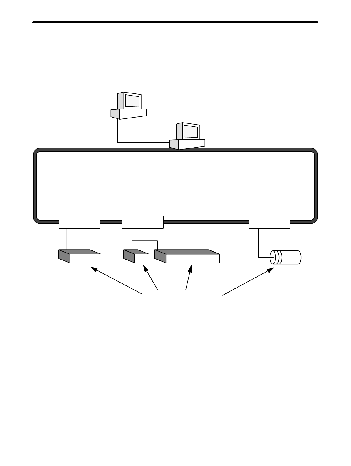
1-1 What is a Control System?
A Control System is the electronic equipment needed to control a particular process. It may include everything from a process control computer, if one is used,
to the factory computer, down through the PCs (and there may be many of them
networked together) and then on down through the network to the control components: the switches, stepping motors, solenoids, and sensors which monitor
and control the mechanical operations.
Process Control Computer
Factory Computer
PCs
PC PC PC
Control Components
A Control System can involve very large applications where many different models of PC are networked together or it could be an application as small as a single
PC controlling a single output device.
2
Page 15
What is a Control System? Section 1-1
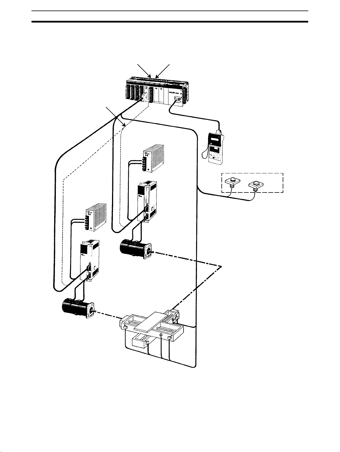
A Position Control System
Position Control Unit
Signal line for
Servomotor
driver control
Power
source
Input Unit
Power
source
DC Servomotor
Driver
PC
Hand-held Programming
Console
Control panel
Control switch
DC Servomotor Driver
DC Servomotor
In the typical Control System example shown above, a PC controls the movement of the workpiece bed across two horizontal axes using Limit Switches and
Servomotors to monitor and control movement.
DC Servomotor
3
Page 16
The Role of the PC Section 1-2
1-2 The Role of the PC
The Programmable Controller, or PC, is the part of the Control System that
directly controls the manufacturing process. According to the program stored in
its memory, the PC accepts data from the input devices connected to it, and uses
this data to monitor the controlled system. When the program calls for some
action to take place, the PC sends data to the output devices connected to it, to
cause that action to take place. The PC may be used to control a simple, repetitive task, or it may be connected to other PCs, or to a host computer in order to
integrate the control of a complex process.
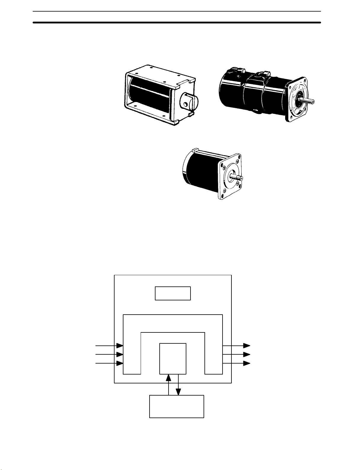
1-2-1 Input Devices
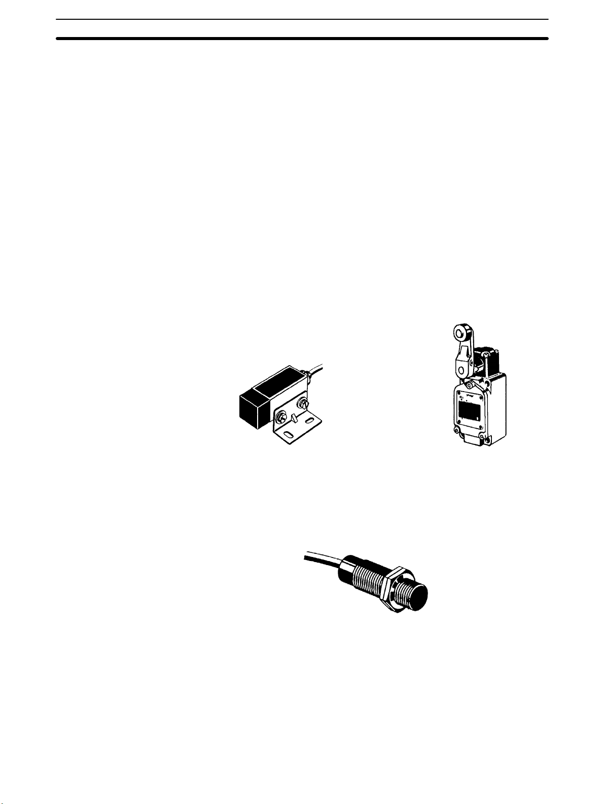
PCs can receive input from either automated or manual devices. The PC could
receive data from the user via a pushbutton switch, keyboard, or similar device.
Automated input could come from a variety of devices: microswitches, timers,
encoders, photosensors, and so on. Some devices, like the Limit Switch shown
below, turn ON or OFF when the equipment actually makes contact with it. Other
devices, like the Photoelectric Switch and Proximity Switch shown below, use
other means, such as light or inductance, in order to get information about the
equipment being monitored.
1-2-2 Output Devices
Photoelectric switch Limit switch
Proximity switch
A PC can output to a myriad of devices for use in automated control. Almost anything that you can think of could be controlled (perhaps indirectly) by a PC. Some
of the most common devices are motors, Solenoids, Servomotors, Stepping
Motors, valves, switches, indicator lights, buzzers, and alarms. Some of these
output devices; such as the motors, Solenoids, Servomotors, Stepping Motors,
4
Page 17
How Does a PC Work? Section 1-3
and valves; affect the controlled system directly. Others; such as the indicator
lights, buzzers, and alarms; provide output to notify personnel.
Solenoid
1-3 How Does a PC Work?
PCs operate by monitoring input signals and providing output signals. When
changes are detected in the signals, the PC reacts, through the user-programmed internal logic, to produce output signals. The PC continually scans the
program in its memory to achieve this control.
Block Diagram of PC
Servomotor
Stepping motor
Power Supply
Signals
from
switches,
sensors,
etc.
Memory
Signals to
Input Output
CPU
Programming
Device
Solenoids,
motors,
etc.
A program for your applications must be designed, and stored in the PC. This
program is then executed as part of the cycle of internal operations of the PC.
5
Page 18

How Does a PC Work? Section 1-3
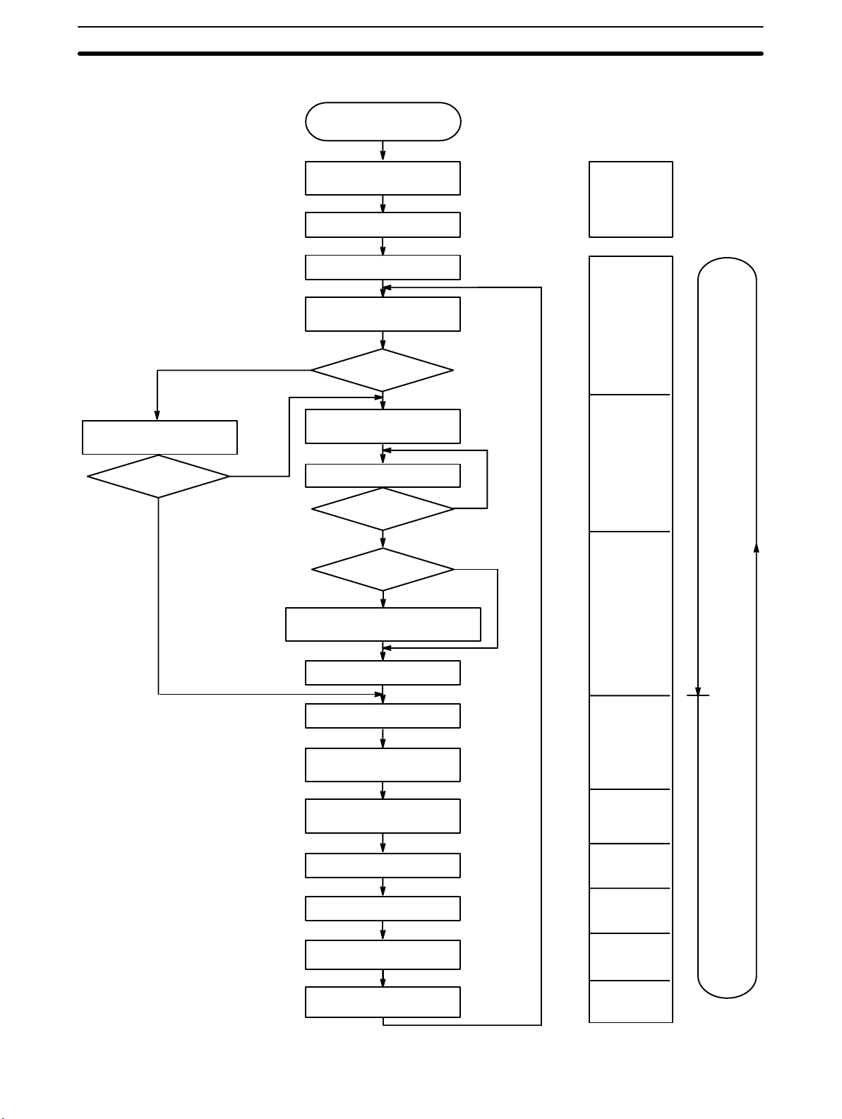
Cycle When a PC operates, that is, when it executes its program to control an external
system, a series of operations are performed inside the PC. These internal
operations can be broadly classified into the following four categories:
1, 2, 3... 1. Common (or overseeing) processes, such as watchdog timer operation and
testing the program memory.
2. Data input and output.
3. Instruction execution.
4. Peripheral device servicing.
Cycle Time The total time required for a PC to perform all these internal operations is called
the cycle time. The flowchart and diagram on the following page illustrate these
internal operations for a typical PC.
Timing is one of the most important factors in designing a Control System. For
accurate operations, it is necessary to have answers to such questions as these:
• How long does it take for the PC to execute all the instructions in its memory?
• How long does it take for the PC to produce a control output in response to a
given input signal?
The cycle time of the PC can be automatically calculated and monitored, but it is
necessary to have an understanding of the timing relationships within the PC for
effective system design and programming.
6
Page 19
How Does a PC Work? Section 1-3
Flowchart of CPU Operation
Sets error flags and turns
ON or flashes indicator
ALARM/ERROR
ERROR
(Solid ON)
ALARM
(Flashing)
Power application
Clears IR area and
resets all timers
Checks I/O Unit connections
Resets watchdog timer
Checks hardware and
Program Memory
NO
Check OK?
Resets watchdog timer and
program address counter
Executes program
End of program?
Initialization on
power-up
Overseeing
processes
YES
Program
execution
NO
YES
SCAN(18)
executed?
NO
YES
Resets watchdog timer and waits
until the set cycle time has elapsed
Calculates cycle time
Resets watchdog timer
Refreshes input bits
and output signals
Services RS-232C
connector
Services Host Link Units
Services Peripheral devices
Services Communications
Boards
Services SYSMAC LINK and
SYSMAC NET Link Units
Cycle time
calculation
I/O refreshing
RS-232C
connector
servicing
Host Link Unit
servicing
Peripheral
device
servicing
Communicatio
ns Board
servicing
SYSMAC LINK
and SYSMAC
NET servicing
PC
cycle
time
7
Page 20

Page 21

SECTION 2
System Configuration and Units
This section describes the system configuration used for the C200HX/C200HG/C200HE PCs and the individual Units used in
the system configuration.
2-1 Basic Configuration 10. . . . . . . . . . . . . . . . . . . . . . . . . . . . . . . . . . . . . . . . . . . . . . . . . . . . . . .
2-1-1 CPU Rack 10. . . . . . . . . . . . . . . . . . . . . . . . . . . . . . . . . . . . . . . . . . . . . . . . . . . . . . .
2-1-2 Expansion I/O Racks 13. . . . . . . . . . . . . . . . . . . . . . . . . . . . . . . . . . . . . . . . . . . . . . .
2-1-3 I/O Connecting Cable 14. . . . . . . . . . . . . . . . . . . . . . . . . . . . . . . . . . . . . . . . . . . . . .
2-2 Units 14. . . . . . . . . . . . . . . . . . . . . . . . . . . . . . . . . . . . . . . . . . . . . . . . . . . . . . . . . . . . . . . . . . .
2-2-1 CPU Units 14. . . . . . . . . . . . . . . . . . . . . . . . . . . . . . . . . . . . . . . . . . . . . . . . . . . . . . .
2-2-2 Memory Cassettes 17. . . . . . . . . . . . . . . . . . . . . . . . . . . . . . . . . . . . . . . . . . . . . . . . .
2-2-3 Communications Boards 18. . . . . . . . . . . . . . . . . . . . . . . . . . . . . . . . . . . . . . . . . . . .
2-2-4 Power Supply Units 19. . . . . . . . . . . . . . . . . . . . . . . . . . . . . . . . . . . . . . . . . . . . . . . .
2-2-5 Backplanes 24. . . . . . . . . . . . . . . . . . . . . . . . . . . . . . . . . . . . . . . . . . . . . . . . . . . . . . .
2-2-6 Standard I/O Units 25. . . . . . . . . . . . . . . . . . . . . . . . . . . . . . . . . . . . . . . . . . . . . . . . .
2-2-7 Group-2 High-density I/O Units 27. . . . . . . . . . . . . . . . . . . . . . . . . . . . . . . . . . . . . .
2-2-8 High-density I/O Units Classified as Special I/O Units 30. . . . . . . . . . . . . . . . . . . .
2-3 Peripheral Devices 31. . . . . . . . . . . . . . . . . . . . . . . . . . . . . . . . . . . . . . . . . . . . . . . . . . . . . . . .
2-3-1 Programming Consoles 31. . . . . . . . . . . . . . . . . . . . . . . . . . . . . . . . . . . . . . . . . . . . .
2-3-2 Ladder Support Software (LSS) 31. . . . . . . . . . . . . . . . . . . . . . . . . . . . . . . . . . . . . .
2-3-3 SYSMAC Support Software (SSS) 32. . . . . . . . . . . . . . . . . . . . . . . . . . . . . . . . . . . .
2-3-4 SYSMAC-CPT Support Software 32. . . . . . . . . . . . . . . . . . . . . . . . . . . . . . . . . . . . .
2-4 Expanded System Configurations 33. . . . . . . . . . . . . . . . . . . . . . . . . . . . . . . . . . . . . . . . . . . .
2-4-1 Required Mounting Conditions 33. . . . . . . . . . . . . . . . . . . . . . . . . . . . . . . . . . . . . . .
2-4-2 Special I/O Units 33. . . . . . . . . . . . . . . . . . . . . . . . . . . . . . . . . . . . . . . . . . . . . . . . . .
2-4-3 Link Systems and Networks 40. . . . . . . . . . . . . . . . . . . . . . . . . . . . . . . . . . . . . . . . .
9
Page 22
Basic Configuration Section 2-1
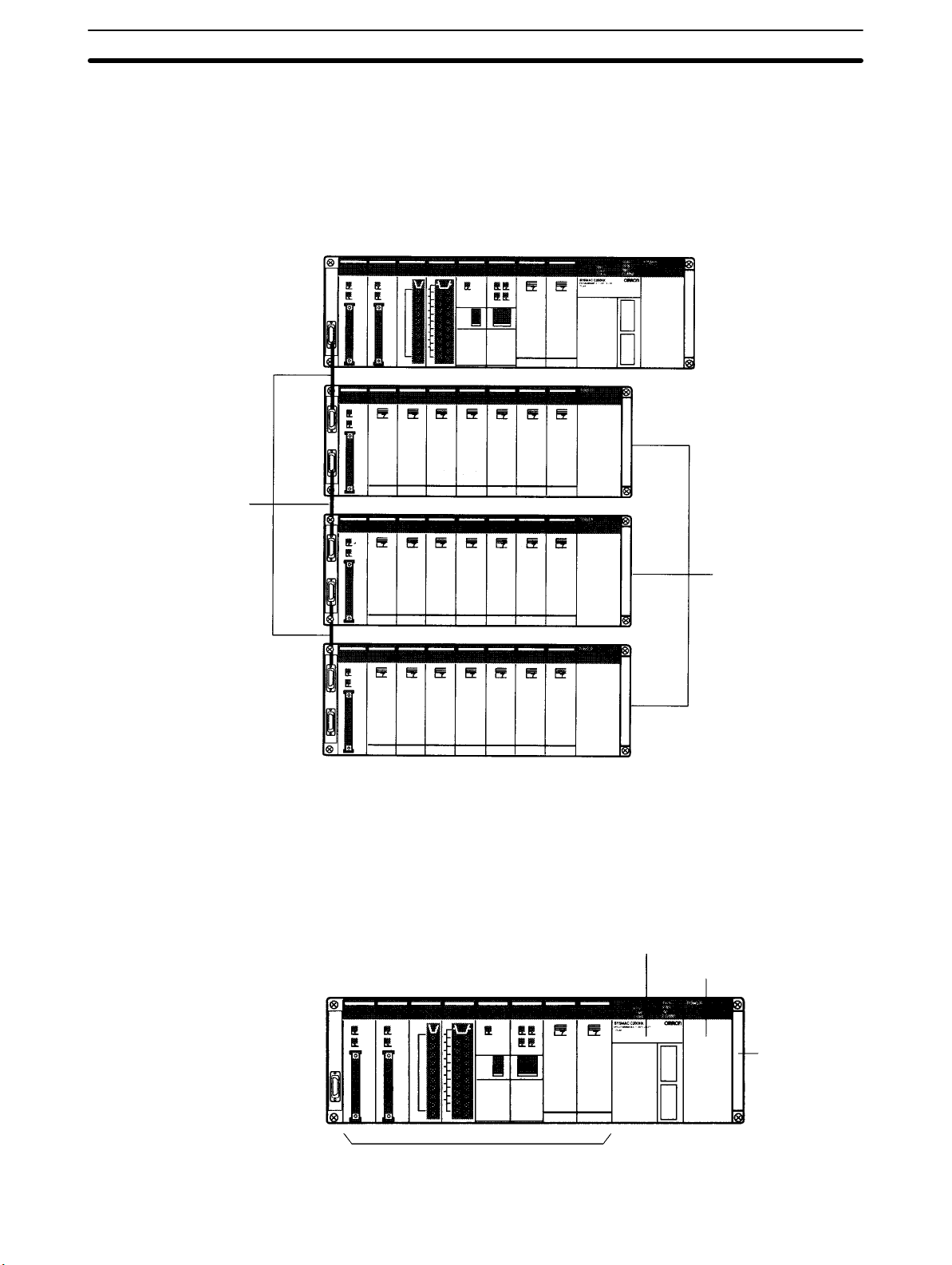
2-1 Basic Configuration
The basic configuration of the PC is shown below. With the C200HX/
C200HG/C200HE, up to two or up to three Expansion I/O Racks (depending on
the CPU Unit) can be connected to the CPU Rack, depending on the number of
I/O points required in the system.
CPU Rack
I/O Connecting Cables
2-1-1 CPU Rack
Expansion I/O Racks
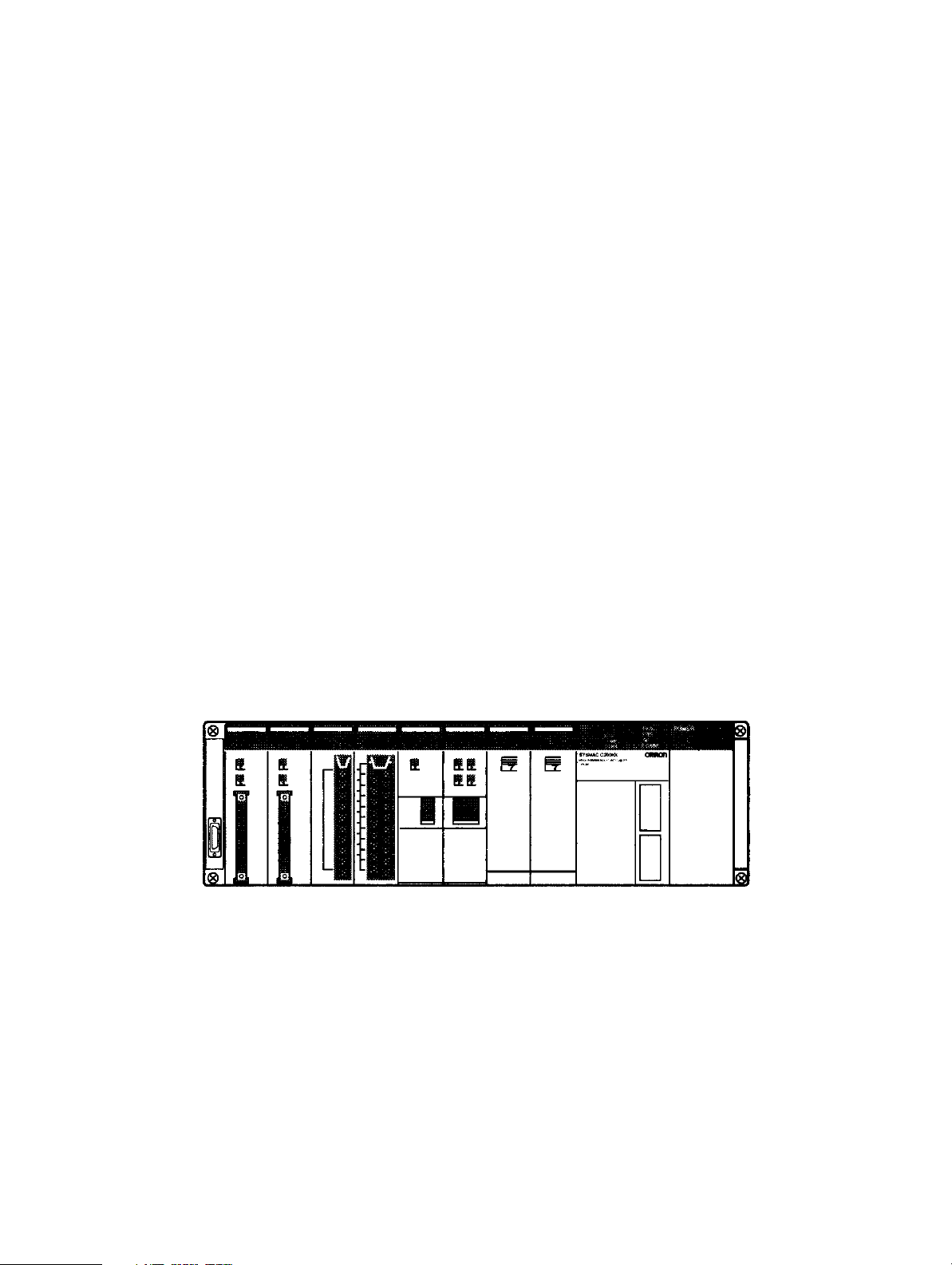
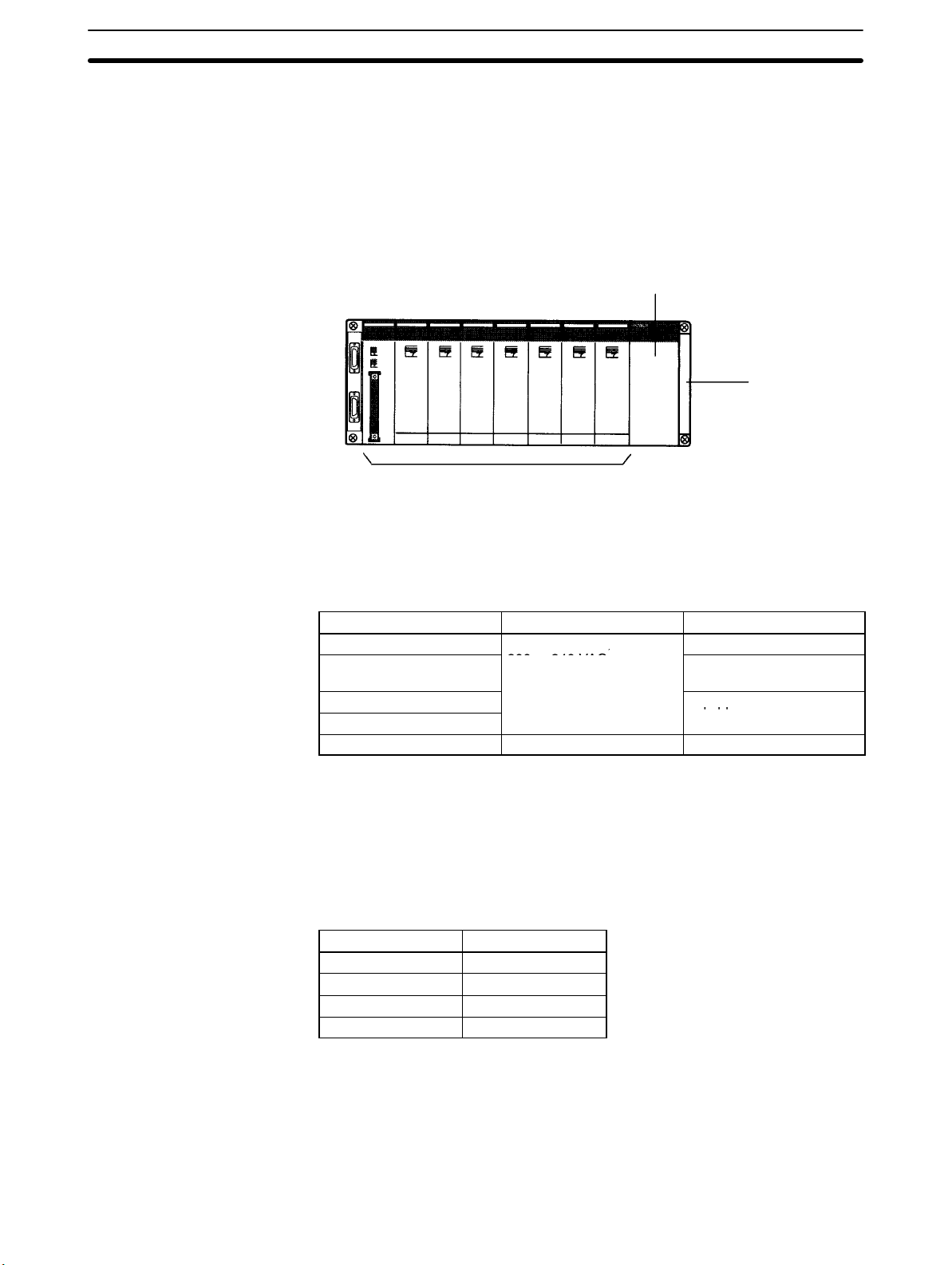
An example of a CPU Rack is shown below. The CPU Rack consists of a CPU
Backplane, CPU Unit, Power Supply Unit, I/O Units, and other special Units.
CPU Unit
Power Supply Unit
10
CPU Backplane
Other Units
Page 23

,
Basic Configuration Section 2-1
Power Supply Units The Power Supply Unit supplies power to the CPU Rack. The Power Supply
Units listed in the following table are available. Refer to 2-2-4 Power Supply
Units for further details.
Model Supply voltage Remarks
C200HW-PA204
C200HW-PA204S
C200HW-PA204R/PA209R
(See note.)
C200HW-PD024 24 VDC ---
Note The C200HW-PA204R/PA209R cannot be used with all combinations of CPU
Units and Backplanes. Refer to page 23, Restrictions for the C200HW-PA204R/
PA209R, for details.
CPU Units The CPU Units listed in the following tables are available. Refer to 2-2-1 CPU
Units for further details on the CPU Units.
100 to 120 VAC,
200 to 240 VAC
---
Provides 24-VDC output
terminals.
Equipped with RUN output
contacts.
Model User
program
memory
C200HE-CPU11-E/ZE 3.2K words 4K words --- 0.3 µs min. 640 points 2 Racks
C200HE-CPU32-E/ZE 7.2K words 6K words --- 0.3 µs min. 880 points 2 Racks
C200HE-CPU42-E/ZE 7.2K words 6K words --- 0.3 µs min. 880 points 2 Racks
C200HG-CPU33-E/ZE 15.2K words 6K words 6K words 0.15 µs min. 880 points 2 Racks
C200HG-CPU43-E/ZE 15.2K words 6K words 6K words 0.15 µs min. 880 points 2 Racks
C200HG-CPU53-E/ZE 15.2K words 6K words 6K words 0.15 µs min. 1,184 points 3 Racks
C200HG-CPU63-E/ZE 15.2K words 6K words 6K words 0.15 µs min. 1,184 points 3 Racks
C200HX-CPU34-E/ZE 31.2K words 6K words 6K words x 3
C200HX-CPU44-E/ZE 31.2K words 6K words 6K words x 3
C200HX-CPU54-E/ZE 31.2K words 6K words 6K words x 3
C200HX-CPU64-E/ZE 31.2K words 6K words 6K words x 3
C200HX-CPU65-ZE 63.2K words 6K words 6K words x 8
C200HX-CPU85-ZE 63.2K words 6K words 6K words x 16
Data
memory
Extended
data memory
(EM)
(18K words)
(18K words)
(18K words)
(18K words)
(48K words)
(96K words)
Instruction
processing
time (basic
instructions)
0.1 µs min. 880 points 2 Racks
0.1 µs min. 880 points 2 Racks
0.1 µs min. 1,184 points 3 Racks
0.1 µs min. 1,184 points 3 Racks
0.1 µs min. 1,184 points 3 Racks
0.1 µs min. 1,184 points 3 Racks
Max. real I/O
points
supported
Max. No. of
Expansion
I/O Racks
11
Page 24
Spec a /O
(C)
oa d
Basic Configuration Section 2-1
Model
C200HE-CPU11-E/ZE Not supported Not supported 10 Units No No No
C200HE-CPU32-E/ZE 10 Units 5 Units 10 Units No Yes Ye s
C200HE-CPU42-E/ZE 10 Units 5 Units 10 Units Yes Yes Yes
C200HG-CPU33-E/ZE 10 Units 5 Units 10 Units No Ye s Yes
C200HG-CPU43-E/ZE 10 Units 5 Units 10 Units Ye s Yes Ye s
C200HG-CPU53-E/ZE 16 Units 8 Units 16 Units No Ye s Yes
C200HG-CPU63-E/ZE 16 Units 8 Units 16 Units Ye s Yes Ye s
C200HX-CPU34-E/ZE 10 Units 5 Units 10 Units No Yes Ye s
C200HX-CPU44-E/ZE 10 Units 5 Units 10 Units Yes Yes Yes
C200HX-CPU54-E/ZE 16 Units 8 Units 16 Units No Yes Ye s
C200HX-CPU64-E/ZE 16 Units 8 Units 16 Units Yes Yes Yes
C200HX-CPU65-ZE 16 Units 8 Units 16 Units Ye s Yes Ye s
C200HX-CPU85-ZE 16 Units 8 Units 16 Units Ye s Yes Ye s
Max. No. of Group-2
High-density I/O Units
64-point Units
(see note 1)
Max. No. of
Special I/O
Units
(see note 2)
RS-232C Clock
(RTC)
Communications
Note 1. Each 64 I/O Unit is treated as two Units.
2. Special I/O Units like the C200H-NC211 that are allocated the words for two
Units are treated as two Units.
3. Unit number settings for Group-2 Units for the following CPU Units must be
between 0 and 9:
C200HE-CPU32/42-E/ZE
C200HG-CPU33/43-E/ZE
C200HX-CPU34/44-E/ZE
Board
CPU Backplane The CPU Backplane is required to mount the CPU Unit and other Units compos-
ing the CPU Rack. The following CPU Backplanes are available depending on
the number of slot required for Units. Refer to 2-2-5 Backplanes for further
details.
Model Number of slots
C200HW-BC031 3
C200HW-BC051 5
C200HW-BC081-V1 8
C200HW-BC101-V1 10
Note When using the C200HW-PA209R Power Supply Unit with an 8-slot or 10-slot
CPU Backplane or Expansion I/O Backplane, be sure to use the C200HWBC081-V1 or C200HW-BC101-V1.
Other Units The other Units that can be mounted to the CPU Rack include the Standard I/O
Units, High-density I/O Units, and Special I/O Units.
12
Page 25
,
qpp
Basic Configuration Section 2-1
2-1-2 Expansion I/O Racks
An example of an Expansion I/O Rack is shown in the following diagram. Expansion I/O Racks consist of and I/O Backplane, Power Supply Unit, I/O Units, and
other Units. Expansion I/O Racks are connected to the CPU Rack to increase
the number of I/O Units and other Units that can be used by the PC. You can
connect up to 2 or up to 3 Expansion I/O Racks to a CPU Rack, the number
depending on the CPU Unit that is used.
Power Supply Unit
I/O Backplane
Other Units
Power Supply Unit The Power Supply Unit supplies power to the Expansion I/O Rack. The Power
Supply Units listed in the following table are available. Refer to 2-2-4 Power Sup-
ply Units for further details.
Model Supply voltage Remarks
C200HW-PA204
C200HW-PA204S
C200HW-PD204R
C200HW-PD209R
C200HW-PD024 24 VDC
100 to 120 VAC,
200 to 240 VAC
---
Provides 24-VDC output
terminals.
Equipped with RUN
output contacts.
Note RUN output contacts cannot be used with Expansion I/O Racks.
I/O Backplane The I/O Backplane is required to mount the Power Supply Unit and other Units
composing the Expansion I/O Rack. The following I/O Backplanes are available
depending on the number of slot required for Units. Refer to 2-2-5 Backplanes
for further details.
Model Number of slots
C200HW-BI031 3
C200HW-BI051 5
C200HW-BI081-V1 8
C200HW-BI101-V1 10
Note When using the C200HW-PA209R Power Supply Unit with an 8 or 10-slot Back-
plane, be sure to use the C200HW-BC081-V1 or C200HW-BC101-V1.
Other Units The other Units that can be mounted to an Expansion I/O Rack include the Stan-
dard I/O Units, High-density I/O Units, and Special I/O Units.
13
Page 26
Units
2-1-3 I/O Connecting Cable
The first Expansion I/O Rack is connected to the CPU Rack, and the second and
third Expansion I/O Racks are connected to the previous Expansion I/O Rack
through I/O Connecting Cable. There are five different lengths of cable available, which can be used as desired to provide the desired distance between
each Rack. The sum of the lengths of all the I/O Connecting Cables connected
within one PC, however, but be 12 m or less.
Model Cable length
C200H-CN311 30 cm
C200H-CN711 70 cm
C200H-CN221 2 m
C200H-CN521 5 m
C200H-CN131 10 m
Section 2-2
2-2 Units
2-2-1 CPU Units
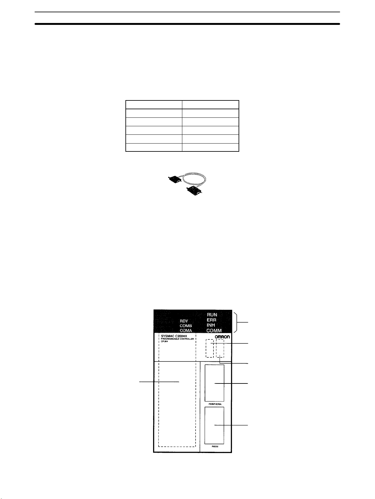
6. Communications Board
compartment
The following diagram shows the components of the CPU Unit as viewed from
the front cover. The numbers in the diagram correspond to the numbers of the
following items in the description.
1. Indicators
2. Memory Casette
compartment
3. DIP Switch
4. Peripheral port
14
5. RS-232C port
Page 27

Units
Section 2-2
1, 2, 3... 1. Indicators
The indicators (LEDs) on the front cover of the CPU Unit operate as
described in the following table.
LED Contents
RUN (green) Lights when the PC is operating normally in MONITOR
or RUN mode.
ERR (red) Flashes if an error occurs that does not stop the CPU
Unit (a non-fatal error).
Lights if an error occurs that stops the CPU Unit (a fatal
error). If a fatal error occurs, the RUN indicator will turn
OFF and the outputs from all Output Units will turn OFF.
INH (orange) Lights when the Load OFF Bit (SR 25215) turns ON. If
the Load OFF Bit is turned ON, the outputs from all
Output Units will turn OFF.
COMM (orange) Lights when the CPU Unit is communicating via the
peripheral or RS-232C port.
2. Memory Casette Compartment
The Memory Cassette compartment contains the built-in RAM and can be
used to mount an optional Memory Cassette. Refer to 3-1-8 Mounting
Memory Cassettes for the mounting methods.
15
Page 28

Units
3. DIP Switch
The DIP switch is used to make various settings that determine who the PC
will operate. The C200HX/C200HG/C200HE CPU Unit has a 6-pin DIP
switch, as shown in the following diagram. The settings of these pins are
listed in the following table.
Pin no. Setting Function
1
ON Writing disabled for user memory.
OFF Writing enabled for user memory.
2
ON Contents of the Memory Cassette automatically read when power is turned on.
OFF Contents of the Memory Cassette not automatically read when power is turned on.
3
ON Programming Console messages displayed in English.
OFF Programming Console messages displayed in the language stored in system ROM. (Messages
displayed in Japanese with the Japanese version of system ROM.)
4
ON Setting function for special instructions enabled.
OFF Setting function for special instructions disabled (default).
5
ON Standard communications parameters (see note) will be set for the following serial communications
ports.
• Built-in RS-232C port
• Peripheral port (only when a CQM1-CIF01/-CIF02 Cable is connected. Does not apply to Program-
ming Console.)
Note 1. Standard communications parameters are as follows:
Serial communications mode: Host Link or peripheral bus; start bits: 1; data length: 7 bits;
parity: even; stop bits: 2; baud rate: 9,600 bps
2. The CX-Programmer running on a personal computer can be connected to the peripheral
port via the peripheral bus using the above standard communications parameters.
OFF The communications parameters for the following serial communications ports will be set in PC
Setup as follows:
• Built-in RS-232C port: DM 6645 and DM 6646
• Peripheral port: DM 6650 and DM 6651
Note When the CX-Programmer is connected to the peripheral port with the peripheral bus, either set
bits 00 to 03 of DM 6650 to 0 Hex (for standard parameters), or set bits 12 to 15 of DM 6650 to 0
Hex and bits 00 to 03 of DM 6650 to 1 Hex (for Host Link or peripheral bus) separately.
6
ON Expansion TERMINAL mode for the Programming Console; AR 0712: ON
OFF Console mode for the Programming Console; AR 0712: OFF
Section 2-2
16
Note All pins are set to OFF for the factory defaults.
4. Peripheral Port
The peripheral port is connected to peripheral devices, such as the Programming Console.
5. RS-232C Port
The RS-232C port is connected to external devices that support an
RS-232C interface, such as personal computers.
6. Communications Board Compartment
The Communications Board compartment is used to mount a Communica-
Page 29

Units
Section 2-2
tions Board. Refer to 3-1-9 Mounting a Communications Board for the
mounting methods.
2-2-2 Memory Cassettes
Memory Cassettes can be optionally mounted to increase memory capacity
over just the built-in RAM. There are two types of Memory Cassette available.
These are shown in the following diagram.
EEPROM Memory Cassette EPROM Memory Cassette
Notch
C200HW-ME
EEPROM Memory Cassette When an EEPROM Memory Cassette is installed in the CPU Unit, the user
memory (UM) and I/O data can be directly read and written. There is no need for
a backup power supply. The Memory Cassette can also be removed from the
CPU Unit and used for storing data.
Model Capacity
C200HW-ME04K 4K words
C200HW-ME08K 8K words
C200HW-ME16K 16K words
C200HW-ME32K 32K words
C200HW-ME64K 64K words
Note The C200HW-ME64K can be used with the C200HX-CPU65-ZE/CPU85-ZE
CPU Units only. It cannot be used with other CPU Units.
EPROM Memory Cassette With an EPROM Memory Cassette, the program is written using a PROM Writer.
The ROM is mounted to the Memory Casette and then installed in the CPU Unit.
I/O data cannot be stored.
Model Capacity
C200HS-MP16K 16K words/32K words
Memory Cassette Settings
EEPROM Memory Cassette Set the DIP switch. For an EEPROM Memory Cassette, set pin no. 1 (write pro-
tect) to either ON or OFF. Setting it to ON will protect the program in the memory
from being overwritten. Setting it to OFF will allow the program to be overwritten.
(The factory setting is OFF.)
EPROM Memory Cassette For an EPROM Memory Cassette, set pin no. 1 (ROM Type Selector) according
to the type of ROM that is mounted.
Pin no. 1 ROM type Model Capacity Access speed
OFF 27256 ROM-JD-B 16K words 150 ns
ON 27512 ROM-KD-B 32K words 150 ns
17
Page 30
Units
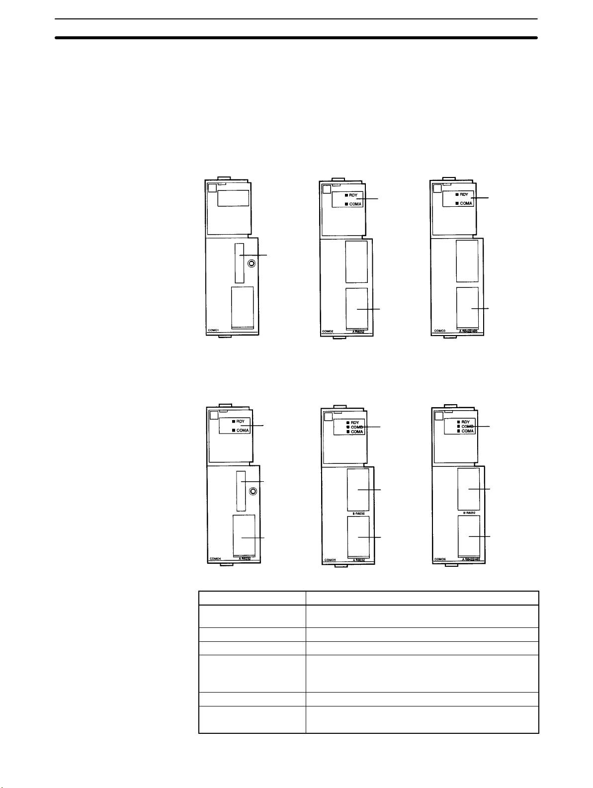
2-2-3 Communications Boards
An optional Communications Board can be mounted in the CPU Unit to provide
communications with the following types of devices/systems through the communications port: SYSMAC LINK Systems, SYSMAC NET Systems, personal
computers, Programmable Terminals (PTs), bar code readers, temperature
controllers, devices with RS-232C or RS-422 interfaces, etc.
The following Communications Boards are available.
C200HW-COM01 C200HW-COM02-V1 C200HW-COM03-V1
Section 2-2
Indicators Indicators
Bus
Connecting
Unit
connector
Port A
(RS-232C)
Port A
(RS-422/
RS-485)
C200HW-COM04-EV1 C200HW-COM05-EV1 C200HW-COM06-EV1
Indicators
Bus
Connecting
Unit
connector
Port A
(RS-232C)
Indicators Indicators
Port B
(RS-232C)
Port A
(RS-232C)
Port B
(RS-232C)
Port A
(RS-422/
RS-485)
18
Model
Specifications
C200HW-COM01 Connection port for SYSMAC LINK, SYSMAC NET, or
other Communications Units.
C200HW-COM02-V1 RS-232C port x 1
C200HW-COM03-V1 RS-422/485 port x 1
C200HW-COM04-EV1 Connection port for SYSMAC LINK, SYSMAC NET, or
other Communications Units.
RS-232C port x 1 (supports protocol macros)
C200HW-COM05-EV1 RS-232C port x 2 (supports protocol macros)
C200HW-COM06-EV1 RS-422/485 port x 1 (supports protocol macros)
RS-232C port x 1 (supports protocol macros)
Page 31

Units
Section 2-2
Note Use either the C200HW-COM01 or a V1 Communications Board for the ZE-ver-
sion C200HX/HG/HE CPU Units.
Indicators (LEDs) The Communications Board indicators on the front panel of the CPU Unit indi-
cate the status of the Board, as described in the following table.
Indicator Color Status Meaning
RDY Green
Not lit The Board cannot be used due to a hardware
error on the Board.
Flashing A setting error has been discovered in the PC
Setup or the protocol data.
Lit The Board is operating properly and
communications are possible.
COMB Orange Flashing Communications are in progress with the
device connected to port B.
COMA Orange Flashing Communications are in progress with the
device connected to port A.
2-2-4 Power Supply Units
Power Supply Units provide power to the CPU Rack and the Expansion I/O
Racks. Power Supply Units are available for either AC or DC power input. The
numbers in the diagram correspond to the numbers of the following items in the
description. (The following diagram shows the C200HW-PA204S.)
Part Names and Functions
/N
L
2
100 to 120 VAC/
200 to 240 VAC
L
1
100 to 120
200 to 240
+24 VDC 0.8 A
1. POWER indicator
2. Terminals for external
connections
Note The AC input terminals may
be indicated as L
L2/N
instead of L2/N and L1 on
some Units. However, there
is no difference in their functions or performance.
L
1
L1/N
/N and L
1
2
1, 2, 3... 1. POWER Indicator
The POWER indicator will be lit whenever the Power Supply Unit is outputting 5 V.
L
2
19
Page 32

short bar on
Units
Section 2-2
2. Terminals for External Connections
These terminals are connected as shown in the diagram below. The numbers in the diagram correspond to the numbers of the following items in the
description.
Supply
voltage
100 to
120 VAC or
200 to
240 VAC
(Select the
voltage using
the metal
short bar on
the voltage
selector
terminals.)
24 VDC 5 VDC, 4.6 A,
Output
capacity
5 VDC, 4.6 A,
30 W
5 VDC, 9 A,
45 W
30 W
Output
terminals
Without Without C200HW-PA204
24 VDC,
0.8 A
Without With C200HW-PA204R
Without With C200HW-PA209R
Without Without C200HW-PD024
RUN output Model
Without C200HW-PA204S
20
Page 33

Units
Terminal Connections
C200HW-PA204: AC Input C200HW-PA204S: AC Input
1. AC Input
2. Voltage selector
terminals
L2/N
100 to 120 VAC/
200 to 240 VAC
Input
L
1
100 to 120
Close
200 to 240
Open
1. AC Input
2. Voltage selector
terminals
Section 2-2
L2/N
100 to 120 VAC/
200 to 240 VAC
Input
L
1
100 to 120
Close
200 to 240
Open
3. LG
4. GR
C200HW-PA204R: AC Input
1. AC Input
2. Voltage selector
terminals
3. LG
4. GR
7. RUN output
5. 24 VDC output
C200HW-PA209R: DC Input
L2/N
100 to 120 VAC/
200 to 240 VAC
Input
L
1
100 to 120
Close
200 to 240
Open
RUN OUTPUT
250 VAC
24 VDC
2 A
1. AC Input
2. Voltage selector
terminals
3. LG
4. GR
7. RUN output
C200HW-PD024: DC Input
3. LG
4. GR
24 VDC 0.8 A
Output
L2/N
100 to 120 VAC/
200 to 240 VAC
Input
L
1
100 to 120
Close
200 to 240
Open
RUN OUTPUT
240 VAC
24 VDC
2 A Resistive
6. DC Input
3. LG
4. GR
1, 2, 3... 1. AC Input (C200HW-PA20jj Only)
Supply either 100 to 120 VAC or 200 to 240 VAC to the AC input terminals. If
one power supply phase of the equipment is grounded, connect the
grounded phase side to the L
/N (or L1/N if so indicated) terminal.
2
2. Voltage Selector Terminals (C200HW-PA20jj Only)
Short these terminals with a metal short bar when 100 to 120 VAC is being
supplied to the AC input terminals.
3. LG
Ground the LG terminal to 100 Ω or less to increase resistance to noise and
protect against possible electrical shock.
24 VDC
21
Page 34

Units
Section 2-2
4. GR
Ground the GR terminal to 100 Ω or less to protect against possible electrical shock.
5. 24 VDC Output (C200HW-PA204S Only)
The 24 VDC output terminals can be used to supply power to DC Input Units.
The combined power consumption for both 5 V and 24 V must be 30 W or
less.
6. DC Input (C200HW-PD024 Only)
Supply 24 VDC to the DC input terminals.
7. RUN Output (C200HW-PA204R/PA209R Only)
The internal contact will turn ON when the CPU Unit is operating in RUN or
MONITOR mode. These terminals are available only on the C200HWPA204R.
22
Page 35

manufacturing
manufacturing
Units
Section 2-2
Restrictions for the
C200HW-PA204R/PA209R
Use the C200HW-PA204R/PA209R Power Supply Unit only with the following
CPU Units and Backplanes. CPU Units and Backplanes with manufacturing
numbers earlier than the ones given cannot be used.
CPU Units
Model
C200HX-CPU65-E 20Z6 or later
C200HX-CPU54-E 2817 or later
C200HX-CPU44-E 19Z6 or later
C200HX-CPU34-E 2417 or later
C200HG-CPU63-E 25Z6 or later
C200HG-CPU53-E 0817 or later
C200HG-CPU43-E 19Z6 or later
C200HG-CPU33-E 1017or later
C200HE-CPU42-E 20Z6 or later
C200HE-CPU32-E 19Z6 or later
C200HE-CPU11-E 20Z6 or later
C200HX/HG/HE-
CPUjj-ZE
All models
Manufacturing number (See below.)
Made in Japan Made in the Netherlands
0147 or later
Backplanes (with C200HW-PA204R)
Model
C200HW-BC031 0617 or later
C200HW-BC051 19Z6 or later
C200HW-BC081 24Z6 or later
C200HW-BC101 20Z6 or later
Manufacturing number (See below.)
Made in Japan Made in the Netherlands
0147 or later
Backplanes (with C200HW-PA209R)
CPU Backplanes I/O Backplanes
C200HW-BC031
C200HW-BC051
C200HW-BC081-V1 (-V1 or later) C200HW-BI081-V1 (-V1 or later)
C200HW-BC101-V1 (-V1 or later) C200HW-BI101-V1 (-V1 or later)
Caution When using the C200HW-PA209R Power Supply Unit, be sure to use only the
!
Same
manufacturing
number as for
C200HW-PA204R.
C200HW-BI031
C200HW-BI051
Same
manufacturing
number as for
C200HW-PA204R.
Backplanes listed in the above table. Using a different Backplane may result in
malfunction due to deterioration of the base or pattern burnout.
Note Manufacturing numbers are as shown in the following diagram.
j j j j
Year (Ex. 1997 = 7)
Month (1 to 9 = Jan to Sep, X/Y/Z = Oct/Nov/Dec
Day (01 to 31)
23
Page 36

Units
2-2-5 Backplanes
CPU Backplane
Section 2-2
There are two types of Backplane: the CPU Backplane, used for the CPU Rack,
and the I/O Backplane, used for Expansion I/O Racks. The Backplane serves to
hold and connect the following types of Unit: the CPU Unit, the Power Supply
Unit, I/O Units, Special I/O Units, etc.
The components of the Backplanes are shown in the following diagrams and
described following them. The numbers in the diagram correspond to the numbers of the following items in the description.
4. Unit mounting slots
1. Backplane
mounting
screw
2. Power Supply
Unit connector
6. Unit lock levers
7. I/O Connecting Cable connector
3. CPU Unit
connector
5. Unit connector
I/O Backplane
4. Unit mounting slots
1. Backplane
mounting
screw
2. Power Supply
Unit connector
5. Unit connector6. Unit lock levers
7. I/O Connecting Cable connector
1, 2, 3... 1. Backplane Mounting Screws
Mount the Backplane firmly using four M4 screws.
2. Power Supply Unit Connector
Connect the Power Supply Unit.
3. CPU Unit Connector
Connect the CPU Unit.
4. Unit Mounting Slots
Mount one Unit to each slot. There are 3, 5, 8, or 10 slots available on the
Backplane depending on the model of Backplane used.
5. Unit Connectors
Connect I/O Units, Special I/O Units, Interrupt Input Units, and/or Analog
Timer Units.
Note Attach a C500-COV01 Connector Cover to any slot that is not being used to pre-
vent dust and dirt from entering the unused connectors.
6. Unit Lock Levers
The lock levers hold the Units in place. Press down on the level and pull up
on the Unit to release the lock.
7. I/O Connecting Cable Connector
Connect the I/O Cable from the CPU Rack to the first Expansion I/O Rack or
between adjacent Expansion I/O Racks to this connector.
24
Page 37

p
p
Units
Section 2-2
2-2-6 Standard I/O Units
The following Standard I/O Units are available.
Input Units
Name Model number Specifications No. of
points
DC Input Unit
AC Input Unit C200H-IA121 100 to 120 VAC 8 pts
AC/DC Input Unit C200H-IM211 12 to 24 VAC/DC 8 pts
Output Units
Name Model number Specifications No. of
Contact Output Unit C200H-OC221 2 A, 250 VAC/24 VDC (For resistive loads) 8 pts
Transistor Output
Unit
Triac Output Unit C200H-OA221 1 A, 250 VAC 8 pts
C200H-ID211 12 to 24 VDC 8 pts
C200H-ID212 24 VDC 16 pts
C200H-IA122/IA122V 100 to 120 VAC 16 pts
C200H-IA221 200 to 240 VAC 8 pts
C200H-IA222/IA222V 200 to 240 VAC 16 pts
C200H-IM212 24 VAC/DC 16 pts
Note The C200H-ID001/002 cannot be used on the following Backplanes: C200HW-
BCjj1/BIjj1.
points
C200H-OC222 2 A, 250 VAC/24 VDC (For resistive loads) 12 pts
C200H-OC225 2 A, 250 VAC/24 VAC (For resistive loads) 16 pts
C200H-OC223 2 A, 250 VAC/24 VDC (For resistive loads)
Independent commons
C200H-OC224 2 A, 250 VAC/24 VDC (For resistive loads)
Independent commons
C200H-OC222V 2 A, 250 VAC/24 VDC (For resistive loads) 12 pts
C200H-OC226 2 A, 250 VAC/24 VDC (For resistive loads) 16 pts
C200H-OC224V 2 A, 250 VAC/24 VDC (For resistive loads)
Independent commons
C200H-OD411 1 A, 12 to 48 VDC 8 pts
C200H-OD211 0.3 A, 24 VDC 12 pts
C200H-OD212 0.3 A, 24 VDC 16 pts
C200H-OD213 2.1 A, 24 VDC 8 pts
C200H-OD214 0.8 A, 24 VDC; source type (PNP); with load short protection 8 pts
C200H-OD216 5 to 24 VDC; source type (PNP) 8 pts
C200H-OD217 5 to 24 VDC; source type (PNP) 12 pts
C200H-OD21A 1.0 A, 24 VDC; source type (PNP); with load short protection 16 pts
C200H-OA222V 0.3 A, 250 VAC 12 pts
C200H-OA223 1.2 A, 250 VAC 8 pts
C200H-OA224 0.5 A, 250 VAC 12 pts
5 pts
8 pts
8 pts
Optional Products
The following optional products are available for use with Standard I/O Units.
• I/O Unit Cover: C200H-COV11
Cover for 10-pin terminal block.
• Space Unit: C200H-SP001
Used for vacant slots.
25
Page 38

Units
Section 2-2
Components
The Standard I/O Units come in three shapes; A-shape, B-shape, and E-shape.
Refer to Appendix D Specifications for the dimensions of each Unit. The numbers in the diagram correspond to the numbers of the following items in the
description.
A-shape I/O Unit (10-terminal Terminal Block) B-shape I/O Unit (19-terminal Terminal Block)
1. I/O Unit lock notch
2. Nameplate
3. I/O indicators:
Indicate ON/OFF
status of points
4. 10-terminal terminal block
4. 19-terminal terminal block
E-shape I/O Unit (10-terminal Terminal Block)
I/O Unit lock notch
Nameplate
I/O indicators
Indicate ON/OFF
status of points
10-terminal terminal block
26
Note The C200H-OC226 is an extended B-shape I/O Unit and its dimensions are dif-
ferent from those of the B-shape I/O Unit shown above.
Page 39

Units
Section 2-2
1, 2, 3... 1. I/O Unit Lock Notch
The lock notch fits into the Backplane to hold the Unit in place.
2. Nameplate
The nameplate shows the model number of the I/O Unit.
3. I/O Indicators (LEDs)
The indicators show the ON/OFF status of the I/O points. The arrangement
of the indicators varies with the model of I/O Unit, as shown in the following
tables.
4. Terminal Block
The terminal block is used to wiring I/O. There terminals blocks are removable and consist of two parts.
Units with 10-terminal
Terminal Blocks
Units with 19-terminal
Terminal Blocks
Appearance Unit type Model numbers
8-point Units ID211, IM211, IA121,
IA221, OC221, and
OA216
8-point Units
F: Fuse burnt out
(with LED)
8-point Units
ALARM indictors
(with LEDs)
5-point Units OD223
Appearance Unit type Model numbers
16-point Units ID212, IA122, IA122V,
12-point Units OC222, OC222V, OD211,
OD213, OD411, OA221,
and OA223
OD214
IA222, IA222V, IM212,
OC225, OC226, OD212,
and OD21A
OD217, OA222V, and
OA224
2-2-7 Group-2 High-density I/O Units
Group-2 High-density I/O Units come in two varieties; C-shape and D-shape.
The shape of the two varieties is the same, but C-shape Units have only one connector, while the D-shape Units have two. C-shape Units have 32 I/O points and
D-shape Units have 64 I/O points.
Group-2 High-density I/O Units can be used with C200H-CPU21/22/23/31 CPU
Racks and Expansion I/O Racks. They cannot be used with Slave Racks.
8-point Units OC224 and OC224V
27
Page 40

Units
C-shape Units (32-point Units)
Section 2-2
Unit Specifications Shape Model
DC Input Unit 12 VDC; 64 pts D C200H-ID111
24 VDC; 32 pts
24 VDC; 64 pts D C200H-ID216
Transistor Output Unit 4.5 VDC,16 mA to
26.4 VDC,100 mA; 32 pts
4.5 VDC,16 mA to
26.4 VDC,100 mA; 64 pts
24 VDC, 0.5 A (5A/Unit); 32 pts C C200H-OD21B
1. I/O Unit lock notch
2. Nameplate
3. I/O indicators
4. I/O number setting switch
C C200H-ID217
C200H-ID218
C200H-ID219
C C200H-OD218
D C200H-OD219
D-shape Units (64-point Units)
5. 40-pin connector
1. I/O Unit lock notch
2. Nameplate
3. I/O indicators LED
4. I/O number setting switch
6. Indicator switch
28
5. 40-pin connectors
Page 41

Units
I/O Indicators
Units with One 40-pin
Connector
Section 2-2
1, 2, 3... 1. I/O Unit Lock Notch
The lock notch fits into the Backplane to hold the Unit in place.
2. Nameplate
The nameplate shows the model number of the I/O Unit.
3. I/O Indicators (LED)
The indicators show the ON/OFF status of the I/O points. The arrangement
of the indicators varies with the model of I/O Unit, as shown in the following
tables.
4. I/O Number Setting Switch
This switch is used to set the I/O number for the Unit. Set the number to
between 0 and F for Units with one 40-pin connector and to between 0 and 8
or A and E for Units with two 40-pin connectors.
5. 40-pin Connectors
The number of connectors depends on the Unit.
6. Indicator Switch
Determines whether the status of connector 1 or connector 2 I/O points are
shown on the I/O indicators.
Appearance Unit type Model numbers
32 points Unit ID216 and ID218
Units with Two 40-pin
Connectors
32 points Unit
F: Fuse burnt out
(with LED)
Appearance Unit type Model numbers
64 points Unit ID111, ID217, and ID219
64 points Unit
F: Fuse burnt out
(with LED)
OD218 and OD21B
OD219
29
Page 42

pp
Units
2-2-8 High-density I/O Units Classified as Special I/O Units
Some High-density I/O Units are classified as Special I/O Units. Up to 10 or up to
16 Special I/O Units can be connected to a PC depending on the CPU Unit that is
used. These Units have two 24-pin connectors. In general, these Units control
32 I/O points, although some Units can control 128 I/O points when set for
dynamic operation.
Refer to Appendix B Specifications for detailed specifications and dimensions of
the Units.
Unit Model Number Specifications
TTL Input Unit C200H-ID501 5 VDC, 32 inputs
DC Input Unit C200H-ID215 24 VDC; 32 inputs
TTL Output Unit C200H-OD501 5 VDC, 32 outputs
Transistor Output Unit C200H-OD215 24 VDC; 32 outputs
TTL I/O Unit C200H-MD501 5 VDC, 16 inputs, 16 outputs
DC Input/Transistor Output Unit
C200H-MD115 12 VDC; 16 inputs, 16 outputs
C200H-MD215 24 VDC; 16 inputs, 16 outputs
1. I/O Unit lock notch
Section 2-2
1, 2, 3... 1. I/O Unit Lock Notch
The lock notch fits into the Backplane to hold the Unit in place.
2. Nameplate
The nameplate shows the model number of the Unit.
3. I/O Indicators (LED)
The indicators show the ON/OFF status of the I/O points.
4. Unit Number Setting Switch
Turn OFF the power supply to the PC and set the unit number to between 0
and F using a flat-blade screwdriver, being careful not to damage the slot or
leave the switch set half-way between two settings.
5. 24-pin Connectors
There are two 24-pin connectors.
2. Nameplate
3. I/O indicators LED
4. Unit number setting switch
5. 24-pin connectors
30
Page 43

Peripheral Devices
2-3 Peripheral Devices
There are various Peripheral Devices that can be use to support C200HX/
C200HG/C200HE operation. These Peripheral Devices are introduced in this
section.
2-3-1 Programming Consoles
There are two Programming Consoles that can be used with the C200HX/
C200HG/C200HE: the C200H-PRO27-E and the CQM1-PRO01-E. The following illustration shows the C200H-PRO27-E Programming Console.
Section 2-3
Connected to Peripheral Port on CPU Unit.
C200H-CN222 (2 m) or
C200H-CN422 (4 m), Connecting
Cable
As shown in the illustration, the C200H-PRO27-E Programming Console connects to the C200HX/C200HG/C200HE CPU Unit with C200H-CN222 or
C200H-CN422 Connecting Cable, which must be purchased separately.
The CQM1-PRO01-E Programming Console comes with 2 m of Connecting
Cable.
2-3-2 Ladder Support Software (LSS)
The LSS is a powerful support software package for the OMRON C-series Programmable Controllers (PCs). The LSS runs on an IBM PC/AT or compatible
personal computer, and can be use to program, monitor and control PCs. While
some PCs require a SYSMAC NET Link Unit, Host Link Unit, or Peripheral Interface Unit to connect the computer running LSS, the C200HX/C200HG/C200HE
can be connected directly to the LSS via it’s peripheral or RS-232C port.
The LSS provides displays of various useful lists when the computer is operated
offline and can be used to monitor operating conditions of the PC, and to read
and write PC data. PC programs can be developed in a mnemonic or ladder diagram form.
The LSS supports the C200HX/C200HG/C200HE only within the functions
available for the C200HS.
C200H-PRO27-E Programming Console
31
Page 44

Peripheral Devices
When working in ladder diagram form, not only the program is displayed but also
other information such as I/O, block, and instruction comments can be input and
displayed. Moreover, the LSS allows more than one PC to be connected to and
monitored using a single computer. The monitoring speed can be accelerated if
the optional S3200-NSB11-E SYSMAC NET NSB is used.
For details concerning LSS, refer to the Ladder Support Software Operation
Manual (W237).
2-3-3 SYSMAC Support Software (SSS)
The SSS is an advanced software application that runs on IBM PC/AT or compatibles and is used to program, monitor, and otherwise control OMRON SYSMAC
C-series PCs and SYSMAC CVM1 PCs. The C200HX/C200HG/C200HE can
be connected directly to a computer running the SSS in exactly the same way as
for the LSS.
The SSS can be used with any of the CVM1 PCs and with all of the many C-series PCs. The SSS automatically switches programming styles and other operations between the various PCs when a PC model is set in the SSS’s System
Setup.
All programs written on the Ladder Support Software or on the CV Support Software can be read and used by the SSS. Programs created for the C2000H or
C200HX/C200HG/C200HE families of PCs can be converted for use with CVM1
PCs so that existing programs can be used with the newer PCs.
The SSS naturally supports all of the functionality for C-series PCs as the LSS,
plus some new functions that facilitate fast, efficient programming and operation.
Section 2-3
2-3-4 SYSMAC-CPT Support Software
The SYSMAC-CPT Support Software is the only support software currently
compatible with the C200Hj-ZE PCs. This software is designed to run on IBM
PC/AT or compatibles and allows you to perform all the operations of the Programming Console as well as many additional ones. PC programs can be written on-screen in ladder-diagram form as well as in mnemonic form. As the program is written, it is displayed on a display, making confirmation and modification
quick and easy. Syntax checks may also be performed on the programs before
they are downloaded to the PC.
The SYSMAC-CPT Support Software does not support any of the original
C200HX/HG/HE CPU Units at present.
32
Page 45

Expanded System Configurations
2-4 Expanded System Configurations
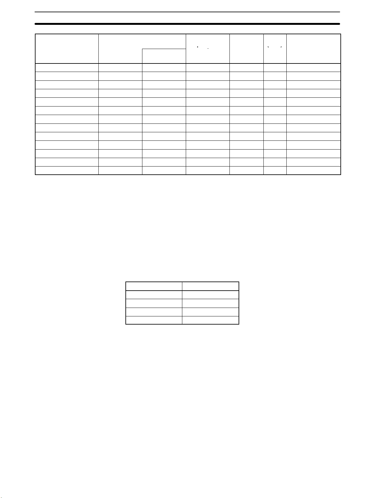
2-4-1 Required Mounting Conditions
A maximum of 16 Special I/O Units including PC Link Units can be mounted to
any slot of CPU, Expansion I/O, and Slave Racks. I/O word numbers 100 to 199,
400 to 459, and DM 1000 to DM 2599 are allocated to each Special I/O Unit.
High-density I/O Units can be mounted Remote I/O Slave Units only when the
Remote I/O Slave Units are connected to C200H-RM001-PV1 or
C200H-RM201 Remote I/O Master Units.
The number of Special I/O Units used with a Slave Rack is limited by data transmission considerations, as shown in the table below. The numbers in the table
indicate the maximum number of Units of groups A, B, C, or D which can be used
with a single Slave Rack.
A B C D
High-speed Counter Units
Position Control Units
(C200H-NC111/112,
C200HW-NC113/213)
ASCII Units
Analog I/O Units
ID Sensor Units
Fuzzy Logic Units
4 units max. 8 units max. 6 units max. 2 units max.
High-density and Mixed I/O
Units
Temperature Control Units
Cam Positioner Units
Heat/Cool Temperature
Control Unit
PID Control Unit
Temperature Sensor Units
Voice Units
Position Control Units
(C200H-NC211,
C200HW-NC413)
Motion Control Units
Section 2-4
Note 1. When a combination of Units from groups A, B, C, and D is used, the number
2-4-2 Special I/O Units
It is possible to connect a variety of Special I/O Units to the C200HX/
C200HG/C200HE Racks.
High-density I/O Units
(Special I/O Units)
The TTL Input Unit, DC Input Unit, TTL Output Unit, Transistor Output Unit, TTL
I/O Unit, and DC Input/Transistor Output Unit are High-density I/O Units.
The C200H-ID501, C200H-OD501, and C200H-MD501 are I/O Units for the
TTL Unit.
Eight input points each of the C200H-ID501, C200H-ID215, C200H-MD501,
C200H-MD115, and C200H-MD215 can be set for pulse input.
A High-density I/O Unit can retrieve pulse input, which is shorter in length than
that of the High-density I/O Unit cycle time, as an input signal when the Highdensity I/O Unit is set for pulse input.
from each group must satisfy both the following equations:
3A + B + 2C + 6D ≤ 12
A + B + C + D ≤ 8
2. Other Units can be added until the total number of Units reaches ten. If PC
Link Units are used, the number of Units including the PC Link Units must
not exceed ten.
33
Page 46

Expanded System Configurations
Section 2-4
The C200H-MD501, C200H-MD115, and C200H-MD215 can each be set for
128 dynamic input points (64 points x two circuits) and the C200H-OD501 and
C200H-OD215 can each be set for 128 dynamic output points (64 points x two
circuits).
High-speed Counter Units The High-speed Counter Units have the following six operation modes.
Linear, circular, preset, gate, latch, and sampling operation modes
The High-speed Counter Units, which have a counting speed of 50 kcps, can be
used for phase-difference pulse input, adding and subtracting pulse input, and
pulse and direction input. The High-speed Counter Units have eight-point output
per single axis.
Rotary Encoder
Position Control Units The Position Control Units have pulse-train output, thus enabling connection to
stepping motor drivers or servomotor drivers.
The C200H-NC111 and C200H-NC112 are for a single axis, and the
C200H-NC211 is for two axes.
Stepping motor
driver or servomotor driver with
pulse-train input.
Stepping motor
or servomotor
34
5-V power supply
Page 47

Expanded System Configurations
Section 2-4
Analog I/O Units The Analog Input (A/D) Units retrieve analog inputs and the Analog Output (D/A)
Unit sends analog outputs.
The following Analog I/O Units are available:
C200H-AD001 with 4-point analog input, C200H-AD002 with 8-point analog
input, C200H-DA001 with 2-point analog output, and C200H-DA002 with
4-point analog output
The Analog Input (AD) Unit is used.
Analog input
Analog output
The Analog Output (DA) Unit is used.
Preamplifier
transducer
Servomotor controller
variable adjuster
Sensor
Motor
Temperature Sensor Units The following table lists Temperature Sensor Unit models and available temper-
ature sensors.
Only one kind of temperature sensor can be connected to the C200H-TS001 or
C200H-TS002. Each Temperature Sensor Unit connects to a maximum of four
temperature sensor inputs.
Model Connectable temperature sensor
C200H-TS001 K (CA)/K (IC)
C200H-TS002 K (CA)/L (Fe-CuNi) (available for DIN)
C200H-TS101 JPt 100 Ω
C200H-TS102 Pt 100 Ω (available for DIN/1989JIS)
Thermocouple: K (CA), J (IC), L (Fe-CuNi)
Platinum resistance thermometer: JPt100 Ω, Pt100 Ω
ASCII Unit BASIC programs can be input to the ASCII Unit via its port 1 from any personal
computer in terminal mode if the personal computer incorporates an RS-232C
interface.
It is possible to write BASIC programs with an IBM PC/AT or compatible.
Port 1
(RS-232C)
Port 1/2
BASIC Program:
Personal computer
Input: Bar code reader
Output: Printer and plasma display
35
Page 48

Expanded System Configurations
Section 2-4
Voice Unit Voice messages can be input from dynamic microphones or cassette tape
recorders and output from loudspeakers or headsets via the Voice Unit.
The Voice Unit incorporates a sentence function and word combination function,
either of which can be selected to record voice messages for 64 seconds maximum.
Voice can be saved on floppy disks with an IBM PC/AT or compatible.
Voice input
Voice output
Voice saving/Re-input
C200H-CN224 Connecting Cable (2 m long with
6- and 25-pin connectors)
Microphone or cassette tape player
Headset or speaker
Personal computer, or PROM Writer
ID Sensor Units The ID Sensor Units are used to construct non-contact information recognition
systems.
By connecting a R/W Head or R/W Antenna to an ID Sensor Unit, data can be
written to the Data Carrier attached to each moving object and the data of the
Data Carrier can be read by the C200HS.
The following models of ID Sensor Units are available.
Electromagnetic induction model: C200H-IDS01-V1
Microwave model: C200H-IDS21
R/W Head
R/W Antenna
C200H-PRO27-E
Programming Console
Data Carrier
36
Page 49

p
E (CRC), B, N, L (IC), U (CC)
Expanded System Configurations
Section 2-4
Fuzzy Logic Unit The C200H-FZ001 Fuzzy Logic Unit incorporates a high-functional fuzzy Logic
processor and allows high-speed fuzzy logic.
A personal computer can be connected to the Fuzzy Logic Unit via RS-232C
cables for software development and monitoring. Use the C500-SU981-E Fuzzy
Support Software for IBM PC/AT or compatible personal computers.
Temperature Control Units Thermocouples or platinum resistance thermometers connect to the Tempera-
ture Control Unit. With the built-in selector of the Temperature Control Unit, ten
kinds of thermocouples or two kinds of platinum resistance thermometers can
be selected.
Select the control output of the Temperature Control Unit from the following.
Model Temperature sensor input Control output
C200H-TC001
C200H-TC002
C200H-TC003
C200H-TC101
C200H-TC102
C200H-TC103 Current output
Temperature Control Unit Data Setting Console
Thermocouple:
R, S, K (CA), J (IC), T (CC),
Platinum resistance thermometer:
JPt100, Pt100
Transistor output
Voltage output
Current output
Transistor output
Voltage output
37
Page 50

p
E (CRC), B, N, L (IC), U (CC)
Expanded System Configurations
Section 2-4
Cam Positioner Unit A single C200H-CP114 Cam Positioner Unit is as powerful as 48 mechanical
cams because it can complete jobs that normally require 48 mechanical cams.
It is possible to set 16-point external output and 32-point internal output as cam
output. The 32-point internal output can be retrieved as data by the C200HS.
Cam Positioner Unit Data Setting Console
Heat/Cool Temperature
Control Units
The Heat/Cool Temperature Control Units measure the temperature of an object
with a connected temperature sensor (thermocouple or platinum resistance
thermometer), and heats and cools according to a preset control mode.
Select the control output of the Heat/Cool Temperature Control Unit from the following.
Model Temperature sensor input Control output
C200H-TV001
C200H-TV002
C200H-TV003
C200H-TV101
C200H-TV102
C200H-TV103 Current output
Heat/Cool Temperature Control Unit Data Setting Console
Thermocouple:
R, S, K (CA), J (IC), T (CC),
Platinum resistance thermometer:
JPt100, Pt100
Transistor output
Voltage output
Current output
Transistor output
Voltage output
38
Page 51

Expanded System Configurations
PID Control Unit The PID Control Unit scales inputs from connected sensors and then carries out
PID control according to preset control mode.
Select the control output of the PID Control Unit from the following.
Model Control output
C200H-PID01 Transistor output
C200H-PID02 Voltage output
C200H-PID03 Current output
PID Control Unit Data Setting Console
Section 2-4
39
Page 52

Expanded System Configurations
Section 2-4
2-4-3 Link Systems and Networks
The C200HX/C200HG/C200HE can be included in an expanded system configuration including a Host Link System (SYSMAC WAY), a PC Link System, Optical or Wired Remote I/O Systems (SYSMAC BUS), CompoBus/S, CompoBus/D, SYSMAC NET Link or SYSMAC LINK System. All of these can be used in
common with the C200HX/C200HG/C200HE. In addition, the following Unit can
be connected: B7A Interface Unit. Specifications for all of these Units are provided in Appendix B Specifications.
SYSMAC LINK Systems OMRON’s SYSMAC LINK System is a communications network that connects
up to 62 nodes to provide data links, data transfers, and datagram services.
CPU Unit
SYSMAC LINK Unit
C200HW-SLK13/SLK14
(optical)
C200HW-SLK23/SLK24
(coaxial cable)
SYSMAC-series PC
• Data links provide automatic transfer of up to 2,966 words of data in the LR
and/or DM Areas.
• Data transfers of up to 256 words each can be implemented by programming
the NETWORK READ (RECV(98)) and NETWORK WRITE (SEND(90))
instructions in the user program.
• Data transfers via datagrams are also available using a command/response
format.
40
• A C200HW-COM01 or C200HW-COM04-E Communications Board and a
C200HW-CE001 or C200HW-CE002 Bus Connection Unit are required to use
a SYSMAC LINK Unit.
The C200H-APS03 Auxiliary Power Supply Unit is used as a backup power supply for optical SYSMAC LINK Systems.
Page 53

Expanded System Configurations
Section 2-4
SYSMAC NET Link Systems OMRON’s SYSMAC NET Link System is an FA-oriented limited-area network
that connects up to 126 nodes to provide datagram services, data transfers, and
data links.
SYSMAC NET Link Unit
C200HS-SNT32
CPU Unit
Line server
Central power supply
FA computer
SYSMAC-series PC
• Data transfers via datagrams are implemented using a command/response
format.
• Data transfers can also be implemented for up to 990 words each by programming the NETWORK READ (RECV(98)) and NETWORK WRITE (SEND(90))
instructions in the user program.
• Data links provide automatic transfer of up to 32 words of data in the LR Area
and/or up to 99 words of data in other data areas.
• A C200HW-COM01 or C200HW-COM04-E Communications Board and a
C200HW-CE001 or C200HW-CE002 Bus Connection Unit are required to use
a SYSMAC NET Link Unit.
The C200H-APS01 and C200H-APS02 Power Supply Adapters are used to
connect to a central power supply (and must be mounted in the slot immediately
to the left of the SYSMAC NET Link Unit).
Note Refer to the SYSMAC NET Link System Manual (W178) for further information.
41
Page 54

Expanded System Configurations
Section 2-4
Host Link Systems A maximum of two Host Link Units can be mounted to slots in either the CPU
Rack or an Expansion I/O Rack. The following Host Link Units are available:
C200H-LK101-PV1 (optical cable)
C200H-LK201-PV1 (RS-232C)
C200H-LK202-V1 (RS-422)
For details, refer to the SYSMAC C-series Rack PCs SYSMAC WAY - Host Link
Units System Manual (W143).
Host Link Unit FA computer
PC Link System A PC Link System can be used to transfer data between PCs by means of LR
0000 through LR 6315. A maximum of two C200H-LK401 PC Link Units can be
mounted to slots in either the CPU Rack or an Expansion I/O Rack. For details,
refer to the PC Link System Manual (W135).
PC Link Unit
Note The PC Link Units must be counted as Special I/O Units.
C200HS
C200HX/C200HG/C200HE
42
Page 55

Expanded System Configurations
Section 2-4
CompoBus/S Systems The CompoBus/S is a high-speed I/O data communications system designed to
meet the needs of time-critical FA applications.
CompoBus/S Master Unit
I/O Terminal
Sensor Terminal
Bit Chain Terminal
• The CompoBus/S Master Unit is mounted to the CPU Rack or an Expansion
I/O Rack. The number of Master Units that can be mounted is indicated below.
Number of Mountable Master Units
C200HX/HE, C200HG-CPU3
j/4j/(-Z)
10 Units when used as 1 Special I/O Unit (i.e., 10 words allocated)
5 Units when used as 2 Special I/O Units (i.e., 20 words allocated)
C200HX, C200HG-CPU5
j/6j/8j(-Z)
16 Units when used as 1 Special I/O Unit (i.e., 10 words allocated)
5 Units when used as 2 Special I/O Units (i.e., 20 words allocated)
Note Unit numbers A to F can be set only with the following CPU Units.
C200HX-CPU54(-Z)
C200HX-CPU64(-Z)
C200HX-CPU65-Z
C200HX-CPU85-Z
C200HG-CPU53(-Z)
C200HG-CPU63(-Z)
• For each Master Unit, up to 32 slaves can be connected for a maximum of 256
points of I/O data communications (8 input words and 8 output words).
• The Special I/O Area is used for data transmissions.
• A wide variety of slaves are available to support relay, sensor, and other I/O.
• Bit Chain Terminals can also be used as slaves to send and receive small
quantities of I/O points at greater distances.
Note The CompoBus/S Master Units must be counted as Special I/O Units.
43
Page 56

Expanded System Configurations
Section 2-4
CompoBus/D Systems The Compobus/D is an I/O data communications system conforming to the
CompoBus/D standard being developed to standardize device-level networks
for FA.
CompoBus/D Master Unit
CQM1 (I/O Link Unit)
I/O Terminal
Adapter
Sensor Terminal
Analog Input Terminal
Analog Output Terminal
• The CompoBus/D Master Unit is mounted to the CPU Rack or an Expansion
I/O Rack. Only one Master Units can be mounted.
• Up to 50 slaves can be connected for a maximum of 1,600 points of I/O data
communications (50 input words and 50 output words).
• The IR Area is used for data transmissions (outputs: IR 50 to IR 99; inputs: IR
350 to IR 399).
• A wide variety of slaves are available to support relay, sensor, analog and other
I/O.
44
Note 1. The CompoBus/D System cannot be used at the same time as a Remote I/O
System.
2. The CompoBus/D Master Units must be counted as Special I/O Units.
3. Slaves made by other manufacturers can be connected as long as they conform to the CompoBus/D standard.
Page 57

Expanded System Configurations
Section 2-4
Remote I/O Systems A maximum of two Optical or Wired Remote I/O Master Units can be mounted to
slots in either the CPU Rack or an Expansion I/O Rack. A maximum total of five
Slave Racks, each with a single Slave Unit, can be connected. C500 Slave
Racks can be used, but each C500 Slave Rack must be counted as two Racks in
calculating the total. For details, refer to the SYSMAC C-series Rack PCs Wired
Remote I/O System Manual (W120) or SYSMAC C-series Optical Remote I/O
System Manual (W136).
Remote I/O Slave Unit
C500 Remote I/O Slave Unit
Optical I/O Units
Remote I/O Slave Unit
C500 Remote I/O Slave Unit
I/O Interface Terminal
I/O terminal
Optical Systems
A maximum total of 64 Optical I/O Units can be connected in an optical system
(32 words).
Note 1. The number of Slave Racks is not related to the number of Master Units.
2. If the number of Optical I/O Units exceeds 32, a B500-RPT01(-P) Repeater
Unit is required.
3. Optical and Wired Units cannot be mixed in the same system.
Wired Systems
A maximum total of 32 I/O Interface Terminals and I/O Terminals (32 words) can
be connected in a wired system.
45
Page 58

Expanded System Configurations
Section 2-4
Controller Link Systems
Controller Link Units can be mounted to C200HX/HG/HE CPU Racks to create
automatic data links that can be freely set between C200HX/HG/HE, CVM1,
and/or CV-series PCs. Controller Link Support Boards are also available so that
IBM PC/AT or compatibles can also be included in the Controller Link System.
Controller Link Systems support a message service that can be used as
required for communications using the SEND and RECV instructions. An example configuration for C200HX/HG/HE PCs is shown below.
Controller Link Unit
(C200HW-CLK21)
C200HX/HG/HE CPU Unit
Communications Board
Bus Connection Unit
(C200HW-CE001/CE002/CE012)
(C200HW-COM01/COM04-EV1)
• Controller Link Systems are wired using multidrop connections with twistedpair cable. Each System can include up to 32 nodes and can extend up to 1 km
for 500-Kbps communications and up to 500 m for 2-Mbps communications.
• For data links, each PC node can read/write up to 8,000 words and each computer node, up to 32,000 words. The data link words can be either set automatically or that can be set manually to more efficiently meet the needs of specific
applications using Controller Link Support Software.
• The message service can be used to send up to 2,012 bytes of data at a time.
• A Communications Board (C200HW-COM01/COM04-EV1) and a Bus Con-
nection Unit (C200HW-CE001/CE002/CE012) are required to mount a Controller Link Unit to a C200HX/HG/HE PC.
• The Controller Link Unit cannot be used with the C200HE-CPU11-E/ZE.
46
Page 59

Expanded System Configurations
Section 2-4
PC Card Unit
PC Card Unit
(C200HW-PCU01)
Memory
card
(SRAM, flash, ATA)
The PC Card Units allows you to expand PC capabilities by adding a PC card.
The PC card can be used to save and retrieve CIO, DM, EM, and other data area
contents between the CPU Unit and the PC card from the ladder-diagram program (using the CMCR instruction). An Ethernet card can also be used to connect to an Ethernet network so that data area or ladder-diagram program contents can be read or written from computers on the network. Examples of PC
Card Unit Applications are shown below.
PC Card Unit Ethernet Set
(C200HW-PCS01-EV1)
C200HX/HG/HE CPU Unit
Bus Connection Unit
(C200HW-CE001/CE002/CE012)
Ethernet Card
Hub
C200HX/HG/HE CPU Unit
Bus Connection Unit
(C200HW-CE001/CE002/CE012)
MAU
Computer
Computer
Note A media attachment unit (MAU) is
required to connect twisted-pair
cable to the CV-series Ethernet Unit.
Ethernet Unit
• Program data read via a PC Card Unit cannot be edited on the Ladder Support
Software.
• PCMCIA2.1 PC cards are used (except for 3.3V cards). Two PC card interface
slots are provided. Up to two type I or type II cards can be mounted, or one type
III card can be mounted, enabling applications of standard SRAM, ATA, flash
memory, and other PC cards.
• A Communications Board (C200HW-COM01/COM04-EV1) and a Bus Connection Unit (C200HW-CE001/CE002/CE012) are required to mount a PC
Card Unit to a C200HX/HG/HE PC.
47
Page 60

Page 61

SECTION 3
Installation and Wiring
This section describes how to install a PC System, including mounting the various Units and wiring the System. Be sure to
follow the instructions carefully during installing. Improper installation can cause the PC to malfunction, resulting in
extremely dangerous situations.
3-1 Installation Environment 50. . . . . . . . . . . . . . . . . . . . . . . . . . . . . . . . . . . . . . . . . . . . . . . . . . .
3-1-1 Installation and Wiring Precautions. 50. . . . . . . . . . . . . . . . . . . . . . . . . . . . . . . . . . .
3-1-2 Installing Racks 51. . . . . . . . . . . . . . . . . . . . . . . . . . . . . . . . . . . . . . . . . . . . . . . . . . .
3-1-3 Mounting Height 53. . . . . . . . . . . . . . . . . . . . . . . . . . . . . . . . . . . . . . . . . . . . . . . . . .
3-1-4 Mounting Dimensions (Units: mm) 54. . . . . . . . . . . . . . . . . . . . . . . . . . . . . . . . . . . .
3-1-5 DIN Track Mounting 55. . . . . . . . . . . . . . . . . . . . . . . . . . . . . . . . . . . . . . . . . . . . . . .
3-1-6 Mounting Units to the Backplane 58. . . . . . . . . . . . . . . . . . . . . . . . . . . . . . . . . . . . .
3-1-7 I/O Connecting Cables 60. . . . . . . . . . . . . . . . . . . . . . . . . . . . . . . . . . . . . . . . . . . . . .
3-1-8 Mounting Memory Cassettes 61. . . . . . . . . . . . . . . . . . . . . . . . . . . . . . . . . . . . . . . . .
3-1-9 Mounting a Communications Board 62. . . . . . . . . . . . . . . . . . . . . . . . . . . . . . . . . . .
3-2 Wiring 63. . . . . . . . . . . . . . . . . . . . . . . . . . . . . . . . . . . . . . . . . . . . . . . . . . . . . . . . . . . . . . . . . .
3-2-1 Power Supply Wiring 63. . . . . . . . . . . . . . . . . . . . . . . . . . . . . . . . . . . . . . . . . . . . . . .
3-2-2 Standard I/O Unit Wiring 68. . . . . . . . . . . . . . . . . . . . . . . . . . . . . . . . . . . . . . . . . . . .
3-2-3 Electrical Noise 74. . . . . . . . . . . . . . . . . . . . . . . . . . . . . . . . . . . . . . . . . . . . . . . . . . .
49
Page 62

Installation Environment Section 3-1
3-1 Installation Environment
This section details the necessary environmental conditions for installing the
PC. Proper installation procedures and a proper environment are essential to
getting the best performance and reliability from your PC.
Caution Static electricity can damage PC components. Your body can carry an electros-
!
tatic charge, especially when the humidity is low. Before touching the PC, be
sure to first touch a grounded metallic object, such as a metal water pipe, in order
to discharge any static build-up.
3-1-1 Installation and Wiring Precautions.
Ambient Conditions Do not install the PC in any of the following locations. Doing so will affect PC life
and may adversely affect operating performance.
• Locations subject to direct sunlight.
• Locations subject to ambient temperatures lower than 0°C or higher than 55°C
(or higher than 45°C when using a Programming Console).
• Locations subject to ambient humidity lower than 35% or higher than 85%.
• Locations subject to condensation as the result of severe changes in tempera-
ture.
• Locations subject to corrosive or flammable gases.
• Locations subject to dust (especially iron dust) or salts.
• Locations subject to shock or vibration.
• Locations subject to exposure to water, oil, or chemicals.
• Take appropriate and sufficient countermeasures when installing systems in
the following locations.
• Locations subject to static electricity or other forms of noise.
• Locations subject to strong electromagnetic fields.
• Locations subject to possible exposure to radioactivity.
• Locations close to power supplies.
Cooling There are two points to consider in order to ensure that the PC does not over-
heat. The first is the clearance between the Racks, and the second is installation
of a cooling fan.
Clearance between Racks The Racks need to have sufficient room between each other to allow for I/O wir-
ing, and additional room to ensure that the I/O wiring does not hamper cooling.
The Racks must also be mounted so that the total length of the Connecting
Cable between all Racks in a given series does not exceed 12 m. As a general
rule, about 70 to 120 mm should be left between any two Racks. Consider factors such as the width of the wiring duct, wiring length, ventilation, and ease of
access to Units, when determining the spacing between Racks. Greater space
is required between Racks when using certain CPU Bus and Special I/O Units.
Refer to the operation manuals for the Units you are using for details.
50
Page 63

Installation Environment Section 3-1
Cooling Fan A cooling fan is not always necessary, but may be needed in some installations.
Try to avoid mounting the PC in a warm area or over a source of heat. A cooling
fan is needed if the ambient temperature may become higher than that specified. If the PC is mounted in an enclosure, install a cooling fan, as shown in the
following diagram, to maintain the ambient temperature within specifications.
Fan
PC
Louver
Noise Resistance Abide by the following precautions to help increase resistance to noise.
• Do not mount the PC in a control panel containing high-voltage equipment.
• Install the PC at least 200 mm from power lines.
• Ground the mounting plate between the PC and the mounting surface.
3-1-2 Installing Racks
The following figures show two views, each consisting of a mounted CPU Rack
and two Expansion I/O Racks. Provide a space of 20 mm minimum on the upper
and lower sides of each duct for ventilation and Unit replacement.
Example Duct Layout
30 mm
40 mm
30 mm
30 mm
118 to 153 mm
CPU
Duct
I/O
Duct
I/O
Each Rack must be mounted vertically, that is, with the printing on the front panels oriented as it would normally read. Racks may be mounted to any sturdy support meeting the environmental specifications.
Whenever possible, the Racks should be mounted to metal-plated mounting
plate that are securely grounded. If all of the Racks cannot be mounted to the
same mounting plate, the individual plates should be securely connected
2
together using 3 wires of at least 2 mm
in cross-sectional area. The Backplanes
are mounted to the plate(s) with four M4 screws each.
Whenever possible, use wiring conduit to hold the I/O wiring. Standard wiring
conduit should be used, and it should be long enough to completely contain the
I/O wiring and keep it separated from other cables.
51
Page 64

Installation Environment Section 3-1
Note Tighten the PC Rack mounting screws, terminal block screws, and cable screws
to the torque of 1.2 N S m.
Caution Racks must be mounted horizontally so that the Units are upright (i.e., not upside
!
down or lying on their backs). The Units can overhead and malfunction if not
mounted properly.
I/O Connecting Cables Each I/O Connecting Cable can be up to 10 m long, but the sum total of all cables
between the CPU Rack and Expansion I/O Racks must be 12 m or less.
The duct work shown in the following diagram is recommended to hold I/O wiring. Although optional, this duct work can be used to house the wires from the I/O
Units that run along the sides of the Racks, keeping the wires from becoming
entangled. This figure illustrates the correct way to mount the Racks.
CPU
Rack
Expansion
I/O Rack
Input duct
Output duct
Power duct
200 mm min.
Breakers,
fuses
Power
equipment
such as
transformers and
magnetic
relays
52
Fuses, relays, timers, etc. (NOT
heat-generating
equipment, power
equipment, etc.)
Terminal blocks
for PC
Terminal blocks for
power equipment
Note When using the C200HW-PA209R Power Supply Unit at an ambient tempera-
ture exceeding 50°C, in order to improve air circulation, ensure that there is a
Page 65

Installation Environment Section 3-1
gap of at least 80 mm between the top of the Power Supply Unit and the top of the
panel, wiring ducts, parts, or any other structures.
3-1-3 Mounting Height
The mounting height of CPU Racks, Expansion I/O Racks, or Slave Racks is
118 mm or 153 mm depending on the type of I/O Units mounted. If Peripheral
Devices or connection cables are attached, the additional dimensions must be
taken into account. Allow sufficient clearance in the control panel in which the
PC is mounted.
80 mm min.
80 mm min.
80 mm min.
80 mm min.
Ducts, etc.
C200HW-PA209R
Ducts, etc.
C200HW-PA209R
Ducts, etc.
118 to 153* mm
Approx. 180 to 223* mm
Note: Figures marked with an asterisk are for
when the C200HW-PA209R is mounted.
53
Page 66

p
p
Installation Environment Section 3-1
3-1-4 Mounting Dimensions (Units: mm)
Backplanes
Four, M4
68 to 108
Four, M4
130
130
CPU Backplane
I/O Backplane
A±0.2
CPU Backplane
I/O Backplane
W
Model A W
C200HW-BC031 246 mm 260 mm
C200HW-BC051 316 mm 330 mm
C200HW-BC081-V1 421 mm 435 mm
C200HW-BC101-V1 491 mm 505 mm
C200HW-BI031 175 mm 189 mm
C200HW-BI051 245 mm 259 mm
C200HW-BI081-V1 350 mm 364 mm
C200HW-BI101-V1 420 mm 434 mm
7
118 ±0.2
80 to 120
118 ±0.2
6
Note The C200HW-PA204R/PA209R cannot be used with all combinations of CPU
Units and Backplanes. Refer to page 23, Restrictions for the C200HW-PA204R/
PA209R, for details.
54
Page 67

p
p
Installation Environment Section 3-1
Backplane Insulation Plates
If there is an electric potential difference between grounds when devices are
wired separately, then use a Backplane Insulation Plate. There are four models
available, corresponding to the number of slots in the Backplane. The dimensions at locations A, B, C, D, and E are shown below in millimeters for each Backplane Insulation Plate model.
135 (118)
Insulation Plates for CPU Backplanes
Specifications Model
For 3 slots C200H-ATT31 261 210 --- --- 246
For 5 slots C200H-ATT51 331 280 --- --- 316
For 8 slots C200H-ATT81 436 385 --- --- 421
For 10 slots C200H-ATTA1 506 455 227.5 270.5 491
110
M4 screws for mounting to PC
(4/5 places)
(B)
C
D
(A)
(E)
E D C B A
5-dia. holes for mounting
Base Insulation Plate
(4/6 places)
6
12 dia.
5 dia.
10
Dimensions (mm)
Insulation Plates for CPU Backplanes
Specifications Model
E D C B A
For 3 slots C200HW-ATT32 190 140 --- --- 175
For 5 slots C200HW-ATT52 260 210 --- --- 245
For 8 slots C200HW-ATT82 365 315 --- --- 350
For 10 slots C200HW-ATTA2 435 385 --- --- 420
Dimensions (mm)
3-1-5 DIN Track Mounting
The PC may be mounted using DIN track if desired. This type of mounting is not
required, and the PC may be directly mounted to any sturdy support meeting the
environmental specifications (refer to Appendix B Specifications). If you want to
mount the PC on DIN track, you can order a DIN Track from OMRON (refer to
Appendix B Standard Models). DIN Tracks come in the two heights shown
below.
Note Never use DIN Track to mount Backplane in locations subject to vibration.
55
Page 68

Installation Environment Section 3-1
DIN Track Mounting Bracket The DIN Track Mounting Bracket shown below is necessary for mounting the PC
to the DIN Track.
DIN Track The following DIN Tracks are available.
Procedure
Model Specification
PFP-50N 50 cm long, 7.3 mm high
PFP-100N 1 m long, 7.3 mm high
PFP-100N2 1 m long, 16 mm high
1, 2, 3... 1. The following diagram is a view of the back of the Backplane. Attach one
Mounting Bracket to the left and right sides of the Backplane as shown
below.
Backplane
DIN Track Mounting
Bracket
There are two Backplane mounting screws each on the left
and right sides of the Backplane. Use these screws to attach
the DIN Track Mounting Brackets to the Backplane.
56
Page 69

Installation Environment Section 3-1
2. Mount the Backplane to the DIN Track so that the claws on the Mounting
Brackets fit into the upper portion of the DIN Track as shown below.
This claw fits into the DIN Track
Backplane
DIN Track Mounting Bracket
DIN Track
3. Loosen the screws attaching the Mounting Brackets to the Backplane. Slide
the Backplane upward as shown below so that the Mounting Bracket and
Backplane clamp securely onto the DIN Track. Tighten the screws.
DIN Track Mounting Bracket
DIN Track
Hold-down bracket
Projections
Slide this screw to the top of the
projection and then tighten it.
57
Page 70

Installation Environment Section 3-1
3-1-6 Mounting Units to the Backplane
The CPU Unit of the C200HX/C200HG/C200HE has no I/O points built in. In
order to complete the PC it is necessary to mount at least one or more I/O Units
to the Backplane. Mount the I/O Unit to the Backplane by locking the top of the
I/O Unit into the slot on the Backplane and rotating the I/O Unit downwards as
shown in the following diagram.
Hook
Backplane
Lock lever
Press down on the yellow lock lever at the bottom of the slot, press the I/O Unit
firmly into position, and then release the yellow lock lever, making sure the connector on the back of the Unit is properly connected.
58
(To remove a Unit, hold down the lock lever with an implement such as a screwdriver.)
Page 71

Installation Environment Section 3-1
CPU Units, I/O Power Supply Units and Slave Units must have the screws on the
bottom tightened with a Phillips screwdriver. The screwdriver must be held at a
slight angle, so be sure to leave enough space below each Rack.
Duct
20 mm min.
Phillips
screwdriver
CPU Unit
Backplane
I/O Power
Supply Unit
Remote
I/O Rack
20 mm min.
Duct
59
Page 72

Installation Environment Section 3-1
3-1-7 I/O Connecting Cables
Each Rack must be mounted vertically, that is with the printing on the front panels oriented as it would normally be read. The Racks should be mounted one
above the other with the CPU Rack uppermost as shown below.
The C200HX/HG/HE is approved by Underwriters Laboratories under the condition that, “The device must be mounted vertically for ventilation purposes.”
Connect the CPU Rack to the first Expansion I/O Rack with an I/O Connecting
Cable and then connect each Expansion I/O Rack in order, again using I/O Connecting Cables. Each I/O Connecting Cable can be up to 10 m long, but the sum
total of all cables between the CPU Rack and Expansion I/O Racks must be 12 m
or less.
Firmly connect the I/O Connecting Cables to the connectors on the Backplanes
and tighten the connector screws. An I/O bus error will occur stopping PC operation if any of the I/O Connecting Cables is disconnected. Be sure to connect
these Cables carefully and securely.
This connector is
not used.
Cover is with a cap.
I/O Connecting
Cable
A hole of 53 mm is diameter is required to pass the connectors on the I/O Connecting Cables through. This hole can be reduced to 33 mm by removing the
hood from the connector, but be sure to reassemble the connector properly and
securely, and secure it with the connector screws.
The pull strength of the Cables is 5 kg. Do not allow more than 5 kg of force to be
applied to the Cables.
Note 1. The sum of the length of all I/O Connecting Cables in one PC must be 12 m
or less.
2. Be careful to connect the Cables in the correct locations.
60
3. Always secure the I/O connection cables with the connector screws.
Page 73

Installation Environment Section 3-1
3-1-8 Mounting Memory Cassettes
Use the following procedure to mount a Memory Cassette.
Caution Be careful to always turn the power off before inserting or removing a Memory
!
Cassette. If a Memory Cassette is inserted into or removed from the CPU Unit
with the power on, it may cause the CPU Unit to malfunction or cause damage to
the memory.
1, 2, 3... 1. Open the Memory Cassette compartment cover.
2. Press the Memory Cassette firmly to the back to mount it.
3. Close the compartment cover.
61
Page 74

Installation Environment Section 3-1
3-1-9 Mounting a Communications Board
Caution Be careful to always turn the power off before inserting or removing a Commu-
!
nications Board. If a Communications Board is inserted into or removed from the
CPU Unit with the power on, it may cause the CPU Unit to malfunction, cause
damage to the memory, or cause errors in communications.
1, 2, 3... 1. Open the Memory Cassette compartment cover.
2. Open the Communications Board compartment cover.
3. Slid the Communications Board in on the supports and press it firmly to the
back of the compartment.
62
Page 75

Wiring
4. Close the compartment covers.
3-2 Wiring
3-2-1 Power Supply Wiring
Section 3-2
AC Power Supply Units
Note 1. Do not remove the protective label from the top of the Unit before wiring. This
label is to prevent wiring clippings and other foreign matter from entering the
Unit during wiring procedures.
2. After completing the wiring, remove the protective label from the top of the
Unit before starting operation. The Unit will overheat if operated with this
label in place.
C200HW-PA204 or
C200HW-PA204S
Power Supply Unit
Screw (3.5 mm head with
self-raising pressure plate)
1:1 isolation
transformer
Voltage selector
24-VDC output
Note The AC input terminals may
be indicated as L
L2/N
instead of L2/N and L1 on
some Units. However, there
is no difference in their functions or performance.
L
1
L1/N
AC power
source
/N and L
1
2
L
2
63
Page 76

Wiring
Section 3-2
C200HW-PA204R or
C200HW-PA209R
Power Supply Unit
Screw (3.5 mm head with
self-raising pressure plate)
1:1 isolation
transformer
AC Power Source
AC power
source
RUN
OUTPUT
Voltage selector
Power
supply
RUN output
• Supply 100 to 120 or 200 to 240 VAC.
• Keep voltage fluctuations within the specified range
Supply voltage Allowable voltage fluctuations
100 to 120 VAC 85 to 132 VAC
200 to 240 VAC 170 to 264 VAC
• If one power supply phase of the equipment is grounded, connect the
grounded phase side to the L
/N (or L1/N if so indicated) terminal.
2
Voltage Selector Shorted: 100 to 120 VAC
Open: 200 to 240 VAC
Short-circuit the voltage selection terminals with the shorting bracket supplied
as an accessory to select 100 to 120 VAC supply voltage. For 200 to 240 VAC
leave them open.
Isolation Transformer Noise between the PC and ground can be significantly reduced by connecting a
1-to-1 isolation transformer. Do not ground the secondary coil of the transformer.
Current Consumption The current consumption will be 120 VA max. (180 VA max. with the C200HW-
PA209) per Rack, and there will be a surge current of at least 5 times the max.
current when power is turned on.
24-VDC Output Use these terminals as the power supply for 24-VDC Input Units. Never exter-
nally short these terminals; PC operation will stop if these terminals are shorted.
These terminals are available on the C200HW-PA204S only.
Although the 24-VDC output can supply up to 0.8 A, the combined power consumption for both 5 V and 26 V must be 30 W or less, i.e., the capacity of the
24-VDC output will be reduced if the Units mounted to the Rack consume a lot of
current. Refer to Appendix C Unit Current and Power Consumption for the consumption current of each Unit.
64
Page 77

Wiring
Section 3-2
The output voltage of the 24-VDC output will vary with the current consumption
of the load as shown in the following table. Be sure to check the current consumption and allowable voltage ranges of the devices connected before using
these terminals.
Load current on 24-VDC
output
Accuracy of 24-VDC output
for lot No. 0197 or later
Accuracy of 24-VDC output
for lot No. 3187 or earlier
Less than 0.3 A 0.3 A or higher
+17%
–11%
+10%
–20%
+10%
–11%
Note Lot numbers are as shown in the following diagram.
0 1 9 7
1997 (Rightmost digit of year)
September (Month: 1 to 9 = Jan to Sep, X/Y/Z = Oct/Nov/Dec
01 (Day: 01 to 31)
Connect a dummy load as shown in the following diagram if the maximum operating voltage of the connected device is 26.4 V (24 V +10%).
24 VDC
OUTPUT
• Resistance of the dummy load:
R=24/(0.3 – I
) (Ω)
L
120 Ω when I
240 Ω when I
= 0.1 A
L
= 0.2 A
L
Not necessary when I
= 0.3 A
L
(IL: Total current of connected devices)
• Capacity of the dummy load resistance:
W=(0.3 – I
) x 26.4 x 5 (Safety factor)
L
30 W (120 Ω) when I
15 W (240 Ω) when I
L
L
= 0.1 A
= 0.2 A
Dummy
load
R
I
L
Connected
device
(Photoelectric
Switch, Sensor Input Unit,
etc.
L
Note Since the dummy load will generate heat, be careful not to allow any combustible
materials to come in contact with the resistor.
65
Page 78

Wiring
Section 3-2
RUN Output These terminals turn ON whenever the CPU Unit is operating in RUN or MON-
ITOR Mode. Use these terminals under the following specifications These terminals are available on the C200HW-PA204R/PA209R only.
Model C200HW-PA204R C200HW-PA209R
Contact
form
Maximum
switching
capacity
SPST-NO
250 VAC: 2 A for resistive loads
0.5 A for inductive loads
24VDC: 2 A
240 VAC: 2A for resistive loads
120 VAC: 0.5 A inductive loads
24 VDC: 2A
Crimp Terminals The terminals on the Power Supply Unit are M3.5, self-raising terminals with
screws.
Use crimp terminals for wiring. Do not connect bare stranded wires
directly to terminals. Tighten the terminal block screws to the torque of 0.8 N S m.
Use round-type crimp terminals (M3.5) having the dimensions shown below.
7 mm max.
Caution Tighten the terminal block screws to the torque of 0.8 N S m. The loose screws
!
may result in short-circuit, malfunction, or burning.
DC Power Supplies
Note 1. Supply power to all of the Power Supply Units from the same source.
2. Be sure to check the setting of the voltage selector before supplying power.
3. Do not forget to remove the label from the top of the Power Supply Unit
before turn on the power supply.
Note 1. Do not remove the protective label from the top of the Unit before wiring. This
label is to prevent wiring clippings and other foreign matter from entering the
Unit during wiring procedures.
2. After completing the wiring, remove the protective label from the top of the
Unit before starting operation. The Unit will overheat if operated with this
label in place.
C200HW-PD024
Power Supply Unit
Screw (3.5 mm head with
self-raising pressure plate)
DC power
source
66
Note To satisfy the EC Directives (Low-voltage
Directives), provide reinforced insulation or
double insulation for the 24-VDC power source
connected to the Power Supply Unit.
Page 79

Wiring
Section 3-2
DC Power Source Supply 24 VDC. Keep voltage fluctuations within the specified range (19.2 to
28.8 V).
Power Consumption The power consumption will be 40 W max. per Rack, and there will be a surge
current of at least 5 times the max. power when power is turned on.
Crimp Terminals The terminals on the Power Supply Unit are M3.5, self-raising terminals with
screws.
Use crimp terminals for wiring. Do not connect bare stranded wires
directly to terminals. Tighten the terminal block screws to the torque of 0.8 N S m.
Use crimp terminals (M3.5) having the dimensions shown below.
7 mm max.7 mm max.
Do not reverse the positive and negative poles when wiring the power supply
terminals.
Supply power to all of the Power Supply Units from the same source.
Do not forget to remove the label from the top of the Power Supply Unit before
turning on the power supply to ensure proper heat dissipation.
For satisfying the EC Directives (Low-voltage Directives), provide reinforced
insulation or double insulation for the DC power supply used for the CPU Unit.
Grounding
Power Supply Unit
L2/N
L
1
To avoid electrical shock, attach a grounded (earth ground) AWG 14 wire (cross-
2
sectional area of at least 2 mm
) to the GR terminal. The resistance to ground
must be 100 Ω or less. Do not use a wire longer than 20 m. Care must be taken,
because ground resistance is affected by environmental conditions such as soil
composition, water content, time of year, and the length of time since the wire
was laid underground.
The Line Ground (LG) terminal is a noise-filtered neutral terminal that does not
normally require grounding. If electrical noise is a problem, however, this terminal should be connected to the Ground (GR) terminal.
PC operation may be adversely affected if the ground wire is shared with other
equipment, or if the ground wire is attached to the metal structure of a building.
67
Page 80

Wiring
Section 3-2
When using an Expansion I/O Rack, the Rack must also be grounded to the GR
terminal. The same ground can be used for all connections.
OK Wrong
Other
devices
Ground to 100 Ω or less.OKGround to 100 Ω or less.
Other
devices
Other
devices
Crimp Terminals The terminals on the Power Supply Unit are M3.5, self-raising terminals with
screws.
Use crimp terminals for wiring. Do not connect bare stranded wires
directly to terminals. Tighten the terminal block screws to the torque of 0.8 N S m.
Use crimp terminals (M3.5) having the dimensions shown below.
7 mm max.7 mm max.
3-2-2 Standard I/O Unit Wiring
Caution Check the I/O specifications for the I/O Units, and consider the following points.
!
• Do not apply a voltage that exceeds the input voltage for Input Units or the
maximum switching capacity for Output Units. Doing so may result in breakdown, damage or fire.
• When the power supply has positive and negative terminals, be sure to wire
them correctly.
Note To satisfy the EC Directives (Low-voltage Directives), provide reinforced insula-
tion or double insulation for the DC power source connected to the DC I/O Unit.
Use a separate power source for the DC I/O Unit from the external power supply
for the Contact Output Unit.
Electric Wires The following electric wires are recommended.
Terminal Block Connector
Electric Wire Size
10-terminal AWG 22 to 18 (0.32 to 0.82 mm2)
2
19-terminal AWG 22 (0.32 mm
)
Note The allowable current capacity of electric wiring differs depending on factors
such as ambient temperature, insulation thickness, etc., so be sure to take these
factors into account when selecting electric wire.
Crimp Terminals The terminals on the Power Supply Unit are M3.5, self-raising terminals with
screws.
Use crimp terminals for wiring. Do not connect bare stranded wires
directly to terminals. Tighten the terminal block screws to the torque of 0.8 N S m.
Use crimp terminals (M3.5) having the dimensions shown below.
7 mm max.7 mm max.
For satisfying the EC Directives (Low-voltage Directives), provide reinforced
insulation or double insulation for the DC power supply used for the I/O Units.
68
Page 81

Wiring
Section 3-2
Wiring Be sure that each Unit is securely mounted. In order to prevent wire scraps and
other objects from getting inside of the Unit, keep the top-surface label on while
wiring the Unit. After the wiring has been completed, be sure to remove the label
in order to allow heat radiation.
During wiring After wiring
Remove the label.
Wire the Units so that they can be easily replaced. In addition, make sure that the
I/O indicators are not covered by the wiring.
Do not place the wiring for I/O Units together or in the same duct as power lines.
Inductive noise can cause errors in operation.
Tighten the terminal screws to the torque of 0.8 N S m.
The terminals have screws with 3.5-mm diameter heads and self-raising pressure plates. Connect the lead wires to the terminals as shown below.
Terminal Blocks Unlock the terminal block of an I/O Unit to remove the terminal block from the I/O
Unit. You do not have to remove the lead wires from the terminal block in order to
remove it from an I/O Unit.
Locks for terminal block.
Unlock to remove the terminal
block from the I/O Unit. Make
sure the terminal block is
locked securely after wiring is
complete.
69
Page 82

Wiring
Section 3-2
I/O Unit Covers A C200H-COV11 Cover is provided as an I/O Unit cover for Units that use 10P
terminal block connectors. After the I/O wiring has been completed, slide the
cover up from the bottom, as shown in the illustration below. These Covers
should be applied whenever the extra protection is required.
Attach
Remove
I/O Unit cover
Input Devices
Observe the following information when selecting or connecting input devices.
DC Input Units The following types of DC input devices can be connected.
Contact output
IN DC Input Unit
COM
NPN open-collector output
+
Output
7 mA
0 V
Sensor
Power
Supply
IN DC Input Unit
COM
70
NPN current output
Current
regulator
PNP current output
+
Output
7 mA
0 V
+
Output
7 mA
0 V
Sensor
Power
Supply
Sensor
Power
Supply
IN DC Input Unit
COM
IN AC/DC Input Unit
COM
Page 83

Wiring
Section 3-2
The circuit below should be used for I/O devices having a voltage output.
Voltage output
AC Input Units
+
Output
0 V
Sensor
Power
Supply
COM
IN DC Input Unit
The circuit below should NOT be used for I/O devices having a voltage output.
Voltage output
+
Output
0 V
Contact output
Sensor
Power
Supply
IN DC Input Unit
COM
IN AC Input Unit
COM
AC Switching
IN AC Input Unit
Proximity
switch
main
circuit
COM
Note When using Reed switch as the input contact for an AC Input Unit, keep the
allowable current to 1 A or greater. If Reed switches with smaller allowable currents are used, the contacts may fuse due to surge currents.
Input Leakage Current When two-wire sensors, such as photoelectric sensors, proximity sensors, or
limit switches with LEDs, are used, the input bit may be turned ON erroneously
by leakage current. In order to prevent this, connect a bleeder resistor across the
input as shown below.
Input
power
supply
Sensor
Bleeder
resistor
R
PC
If the leakage current is less than 1.3 mA, there should be no problem. If the leakage current is greater than 1.3 mA, determine the resistance (R) and power rating (W) for the bleeder resistor using the following formulas.
71
Page 84

Wiring
For standard I/O Units:
I = leakage current in mA
R =
W =
7.2
––––––
2.4 x I – 3
2.3
–––
R
kΩ max.
W min.
The previous calculations are based on the following equations.
Section 3-2
Precautions when
Connecting a Two-wire
DC Sensor
1, 2, 3... 1. Relation between voltage when the PC is ON and the sensor residual volt-
Input voltge (24)
Input current (10)
Input voltage (24)
Input current (10)
R
Input voltage (24) Tolerance (4)
v OFF voltage (3)
I
W w
R
R )
Input voltage (24)
When using a two-wire sensor with a 12-VDC or 24-VDC input device, check
that the following conditions have been met. Failure to meet these conditions
may result in operating errors.
age:
x VCC – V
V
ON
R
2. Relation between voltage when the PC is ON and sensor control output
(load current):
(min) x ION x I
I
OUT
= (VCC – VR – 1.5 [PC internal residual voltage])/R
I
ON
When ION is smaller than I
OUT
(max.)
IN
(min), connect a bleeder resistor R. The
OUT
bleeder resistor constant can be calculated as follows:
R x (V
– VR)/(I
CC
Power W y (V
CC
(min.) – ION)
OUT
– VR)2/R × 4 [allowable margin]
Note The residual voltage in the PC is 4.0 V for the following Units:
C200H-ID211/ID212/IM211/IM212/INT01
The residual voltage is 1.5 V for all other Units.
72
Page 85

Wiring
Section 3-2
3. Relation between current when the PC is OFF and sensor leakage current:
I
y I
OFF
Refer to Input Leakage Current later in this section for details.
leak
Output Circuits
Output Short-circuit
Protection
The I
values differ for each Unit, but is always 1.3 mA for Input Units
OFF
whose OFF current specifications are not given.
DC Input Unit
Two-wire sensor
: Power voltage
V
CC
V
: PC ON voltage
ON
: PC ON current
I
ON
I
: PC OFF current
OFF
: PC input impedance
R
IN
R
V
R
V
CC
R
IN
V
: Sensor output residual current
R
I
: Sensor control current (load current)
OUT
: Sensor leakage current
I
leak
R: Bleeder resistance
If a load connected to the output terminals is short-circuited, output elements
and printed boards may be damaged. To guard against this, incorporate a
fuse in the external circuit.
Transistor Output Residual
Voltage
When connecting TTL circuits to transistor Output Units, it is necessary to connect a pull-up resistor and a CMOS IC between the two. This is because of the
residual voltage left on the transistor output after the output turns OFF.
Output Leakage Current If there is a possibility of leakage current causing a transistor or triac to malfunc-
tion, connect a bleeder resistor across the output as shown below.
OUT
PC
COM
L
R
Bleeder resistor
Load power supply
Determine the value and rating for the bleeder resistor using the following formula.
V
ON
R
–––
I
Where
= ON voltage of the load in V
V
ON
I = leakage current in mA
R = bleeder resistance in kΩ
73
Page 86

Wiring
Output Surge Current When connecting a transistor or triac Output Unit to an output device having a
high surge current (such as an incandescent lamp), care must be taken to avoid
damage to the Output Unit. The transistor and triac Output Units are capable of
withstanding a surge current of ten times the rated current. If the surge current
for a particular device exceeds this amount, use the circuit shown below to protect the Output Unit.
Section 3-2
OUT
L
+
PC
COM
Another way of protecting the Output Unit lets the load draw a small current
(about one third the rated current) while the output is OFF, significantly reducing
the surge current. This circuit (shown below) not only reduces the surge current,
but also reduces the voltage across the load at the same time.
OUT
R
R
L
+
PC
COM
3-2-3 Electrical Noise
I/O Signal Lines
74
Whenever possible, place I/O signal lines and power lines in separate ducts or
tubes. If placing them together cannot be avoided, use shielded cable to minimize the effects, and connect the shielded end to the GR terminal.
1 = I/O cables
2 = Power cables
Suspended duct
In-floor duct Conduits
Page 87

Wiring
Inductive Load Surge Suppressor
When an inductive load is connected to an I/O Unit, it is necessary to connect a
surge suppressor or diode in parallel with the load as shown below. This is so
that the back EMF generated by the load will be absorbed.
Section 3-2
IN
OUT
COM
OUT
COM
Diode
COM
Surge suppressor
DC input
L
L
Diode
L
Contact Output Unit
Triac Output Unit
Contact Output Unit
Transistor Output Unit
Note Use surge suppressors and diodes with the following specifications.
+
Surge Suppressor
Resistance: 50 Ω
Capacitor: 0.47 µF
Voltage: 200 V
Diode
Leading-edge peak inverse voltage: At least 3 times load voltage
Average rectified current: 1 A
75
Page 88

Wiring
External Wiring
Section 3-2
If power cables must be run alongside the I/O wiring (that is, in parallel with it), at
least 300 mm must be left between the power cables and the I/O wiring as shown
below.
Low current cable
1
Control cable
2
300 mm min.
300 mm min.
Power cable
3
Class-3 ground
Where: 1 = I/O wiring
2 = General control wiring
3 = Power cables
If the I/O wiring and power cables must be placed in the same duct (for example,
where they are connected to the equipment), they must be shielded from each
other using grounded metal plates.
Metal plate (iron)
200 mm min.
123
Interlock Circuits
Class-3 ground
Where: 1 = I/O wiring
2 = General control wiring
3 = Power cables
When the PC controls an operation such as the clockwise and counterclockwise operation of a motor, provide an external interlock such as the one
shown below to prevent both the forward and reverse outputs from turning
ON at the same time.
Interlock circuit
00501
PC
00502
MC2
MC1
Motor clockwise
MC1
Motor counterclockwise
MC2
76
Page 89

Wiring
Power Interruptions
Section 3-2
This circuit prevents outputs MC1 and MC2 from ever both being ON at the same
time. Even if the PC is programmed improperly or malfunctions, the motor is protected.
A sequential circuit is built into the PC to handle power interruptions. This circuit
prevents malfunctions due to momentary power loss or voltage drops. A timing
diagram for the operation of this circuit is shown below.
The PC ignores all momentary power failures if the interruption lasts no longer
than 10 ms (no longer than 2 ms for a DC Power Supply). If the interruption lasts
between 10 and 25 ms (between 2 and 5 ms for a DC Power Supply), the interruption may or may not be detected. If the supply voltage drops below 85% of the
rated voltage for longer that 25 ms (less for the DC Power Supply), the PC will
stop operating and the external outputs will be automatically turned OFF.
Operation is resumed automatically when the voltage is restored to more than
85% of the rated value. The diagram below shows the timing of PC operation
and stopping during a power interruption. The time it takes to detect the power
failure is shorter when the power supply is DC. Also, the voltage value for which
the C200HX/HG/HE will stop due to a drop in the power supply voltage will be
lower than that for AC.
Power supply
Power failure detection signal
+5 V
CPU Unit operating voltage
Power supply reset
Power
interrupted
Power
restored
Time lapse until
detection
77
Page 90

Page 91

Programming Console Operation
This section describes the function of the Programming Console and its connection methods.
4-1 Using the Programming Console 80. . . . . . . . . . . . . . . . . . . . . . . . . . . . . . . . . . . . . . . . . . . . .
4-1-1 Nomenclature 80. . . . . . . . . . . . . . . . . . . . . . . . . . . . . . . . . . . . . . . . . . . . . . . . . . . . .
4-1-2 Connecting the Programming Console 81. . . . . . . . . . . . . . . . . . . . . . . . . . . . . . . . .
4-2 Checking Initial Operation 82. . . . . . . . . . . . . . . . . . . . . . . . . . . . . . . . . . . . . . . . . . . . . . . . . .
SECTION 4
79
Page 92

Using the Programming Console Section 4-1
4-1 Using the Programming Console
4-1-1 Nomenclature
The front panel of the Programming Console is shown below, taking the
C200H-PRO27-E as an example.
C200H-PRO27-E Programming Console
LCD area
Mode selector switch
Instruction keys
Numeric keys
Cassette jacks
Operation keys
LCD Area This window displays the program contents and monitor status.
Mode Selector Switch PROGRAM MODE: Used for creating programs.
RUN MODE: Used for executing the programs.
MONITOR MODE: Used for monitoring PC status.
Keys Instruction, numeric, and operation keys are used for inputting the program and
data.
Note 1. The operations of C200H-PRO27-E and CQM1-PRO01-E Programming
Consoles are the same.
2. The following keys look different but have the same functions.
AR
HR
HR
80
SET
RESET
PLAY
SET
REC
RESET
Page 93

Using the Programming Console Section 4-1
4-1-2 Connecting the Programming Console
There are two Programming Console models that can be used with the C200HX/
C200HG/C200HE: the C200H-PRO27-E and the CQM1-PRO01-E. The following illustration shows how a Programming Console (a C200H-PRO27-E in this
case) connects to the C200HX/C200HG/C200HE CPU Unit.
C200H-CN222 or C200H-CN422
Connecting Cable
C200H-PRO27-E
Programming Console
As indicated in the illustration, the C200H-PRO27-E Programming Console
connects to the C200HX/C200HG/C200HE CPU Unit with C200H-CN222 (2 m)
or C200H-CN422 (4 m) Connecting Cable, which must be purchased separately.
The CQM1-PRO01-E Programming Console comes with 2 m of Connecting
Cable.
81
Page 94

Checking Initial Operation
4-2 Checking Initial Operation
After the Programming Console has been connected, it can be used to check
initial C200HX/C200HG/C200HE operation. Make sure that the Programming
Console is properly connected and that the correct power supply is being provided, and then follow the procedure outlined below.
1, 2, 3... 1. Check to be sure that the Programming Console is in PROGRAM mode.
2. Turn on the power to the PC and check the CPU Unit indicators. The green
POWER indicator should light.
RUN
Section 4-2
MONITOR
PROGRAM
3. Check the Programming Console display and input the password (Clear
and then Monitor Keys). If operation is normal, the display should appear as
shown below.
<PROGRAM>
PASSWORD
<PROGRAM> BZ
Indicates the mode set by the mode selector switch.
Note If the mode is not indicated, turn off and restart the power supply.
4. After checking PC operation, turn off the power. If operation is not normal,
refer to 5-1 Troubleshooting.
82
Page 95

SECTION 5
Troubleshooting, Inspections, and Maintenance
The C200HX/C200HG/C200HE provides self-diagnostic functions to identify many types of abnormal system conditions.
These functions minimize downtime and enable quick, smooth error correction.
This section provides information on hardware and software errors that occur during PC operation. It also provides inspection
and maintenance information that can be used to help prevent the occurrence of errors.
5-1 Troubleshooting 84. . . . . . . . . . . . . . . . . . . . . . . . . . . . . . . . . . . . . . . . . . . . . . . . . . . . . . . . . .
5-2 Inspection and Maintenance 87. . . . . . . . . . . . . . . . . . . . . . . . . . . . . . . . . . . . . . . . . . . . . . . . .
5-2-1 Replacing Output Unit Fuses 87. . . . . . . . . . . . . . . . . . . . . . . . . . . . . . . . . . . . . . . . .
5-2-2 Replacing Relays 88. . . . . . . . . . . . . . . . . . . . . . . . . . . . . . . . . . . . . . . . . . . . . . . . . .
5-2-3 Batteries 91. . . . . . . . . . . . . . . . . . . . . . . . . . . . . . . . . . . . . . . . . . . . . . . . . . . . . . . . .
5-3 Inspections 92. . . . . . . . . . . . . . . . . . . . . . . . . . . . . . . . . . . . . . . . . . . . . . . . . . . . . . . . . . . . . .
83
Page 96

Troubleshooting Section 5-1
5-1 Troubleshooting
CPU Racks and Expansion I/O Racks
Error Probable cause Possible correction
POWER indicator does not light.
RUN indicator does not light. The program has an error (no END
RUN indicator is lit, but RUN output
does not turn on.
Relays do not operate from a
particular number onwards.
Outputs (or inputs) turn ON for
particular Relay numbers.
All the bits from a particular Unit turn
ON.
The voltage selector terminal setting is
wrong. (A 100-VAC voltage is used
when set to 200 VAC.)
The 24-V output terminals are
externally shorted.
An internal fuse has blown.
The Power Supply Unit is broken. (A
200-VAC voltage was used when set
to 100 VAC.)
There is a short-circuit in the internal
power supply. (There is a short-circuit
in the 5/26-VDC supplied by the
Power Supply Unit in a Unit on the
Rack.)
instruction).
A power supply line is defective. Replace the CPU Unit.
Special I/O Units are assigned
overlapping unit numbers.
A Slave Unit’s power supply is turned
off, or no Unit is set as the terminator.
The power circuit is defective. Replace the CPU Unit.
The I/O bus is defective. Replace the Backplane.
Correct the voltage selector terminal
setting.
Correct the wiring.
Replace the Power Supply Unit.
Replace the Unit with the short-circuit.
Correct the program.
Correct the unit number assignments.
Turn on the power to the Slave Unit,
or set a Unit as the terminator.
84
Page 97

pu s u O
pp
pp
pg
gy gp
Troubleshooting Section 5-1
Input Units
Error Probable cause Possible correction
Indicator lights are turned off, and no
inputs turn ON.
Indicator lights are turned ON, but no
inputs turn ON.
All inputs remain ON, and will not turn
OFF.
Inputs do not turn ON for particular
Relay numbers.
Inputs do not turn OFF for particular
Relay numbers.
Inputs are turning ON and OFF
irregularly.
Malfunctioning Relays are in groups of
eight.
Operation is normal, but the input
indicator does not light.
No external input power supply is
provided.
The external input voltage is low. Supply the rated voltage.
Terminal screws are loose. Tighten the terminal screws.
Terminal block connectors are making
poor contact.
The input circuit is defective. Replace the Unit.
The input circuit is defective. Replace the Unit.
An input device is defective. Replace the input device.
Input wiring is disconnected. Check the input wiring.
Terminal screws are loose. Tighten the terminal screws.
Terminal block connectors are making
poor contact.
The ON time for external inputs is too
short.
The input circuit is defective. Replace the Unit.
An input bit address is used for an
OUT instruction in the program.
The input circuit is defective. Replace the Unit.
An input bit address is used for an
OUT instruction in the program.
The external input voltage is low. Supply the rated voltage.
There is malfunctioning due to noise. Apply noise countermeasures such as
Terminal screws are loose. Tighten the terminal screws.
Terminal block connectors are making
poor contact.
Common terminal screws are loose. Tighten the terminal screws.
Terminal block connectors are making
poor contact.
The CPU Unit is defective. Replace the CPU Unit.
The LED is defective. Replace the Unit.
Provide a power supply.
Securely lock the connectors, or
replace them if necessary.
Securely lock the connectors, or
replace them if necessary.
Adjust the input device.
Correct the program.
Correct the program.
installing a surge suppressor,
installing an isolation transformer, and
using shielded cables.
Securely lock the connectors, or
replace them if necessary.
Securely lock the connectors, or
replace them if necessary.
85
Page 98

p
g, p
g, p
ON
g, p
g, p
pg
gy gp
Troubleshooting Section 5-1
Output Units
Error Probable cause Possible correction
No outputs turn ON.
Outputs all fail to turn OFF. The output circuit is defective. Replace the Unit.
Indicators do not light, and the outputs
for particular Relay numbers do not
turn ON.
Indicators light, but the outputs for
particular Relay numbers do not turn
.
Indicator lights are off, but the outputs
for particular Relay numbers do not
turn OFF.
Indicators light, and the outputs for
particular Relay numbers do not turn
OFF.
Outputs are turning ON and OFF
irregularly.
Malfunctioning Relays are in groups of
eight.
Operation is normal, but the output
indicator does not light.
A load power supply is not provided. Provide the power supply.
The load power supply voltage is low. Provide the rated voltage.
Terminal screws are loose. Tighten the terminal screws.
Terminal block connectors are making
poor contact.
A fuse is blown. Replace the fuse.
I/O bus connectors are making poor
contact.
The output circuit is defective. Replace the Unit.
The output ON time is too short. Correct the program.
The output circuit is defective. Replace the Unit.
The program’s OUT instruction bit
addresses overlap.
An output device is defective. Replace the output device.
Output wiring is disconnected. Check the output wiring.
Terminal screws are loose. Tighten the terminal screws.
Terminal block connectors are making
poor contact.
Output Relays are defective. Replace the Relays.
The output circuit is defective. Replace the Unit.
Output Relays are defective. Replace the Relays.
There is faulty restoration due to
leakage current or residual current.
The output circuit is defective. Replace the Unit.
The program’s OUT instruction bit
addresses overlap.
The load power supply voltage is low. Supply the rated voltage.
The program’s OUT instruction bit
addresses overlap.
There is malfunctioning due to noise. Apply noise countermeasures such as
Terminal screws are loose. Tighten the terminal screws.
Terminal block connectors are making
poor contact.
Common terminal screws are loose. Tighten the terminal screws.
Terminal block connectors are making
poor contact.
A fuse is blown. Replace the fuse.
The CPU Unit is defective. Replace the CPU Unit.
The LED is defective. Replace the Unit.
Securely lock the connectors, or
replace them if necessary.
Replace the Unit.
Correct the program.
Securely lock the connectors, or
replace them if necessary.
Replace the external load or add a
dummy resistor.
Correct the program.
Correct the program.
installing a surge suppressor,
installing an isolation transformer, and
using shielded cables.
Securely lock the connectors, or
replace them if necessary.
Securely lock the connectors, or
replace them if necessary.
86
Page 99

,
,
Inspection and Maintenance
5-2 Inspection and Maintenance
5-2-1 Replacing Output Unit Fuses
The following Output Units each contain one fuse. Replace the fuse if the fuse
indicator lights. The OD211, OD212, OA222, and OA224 Output Units do not
have fuse indicators. Replace the fuses on these Units if outputs are not produced.
Unit Fuse indicator Capacity
C200H-OD411 Ye s
C200H-OD211 No
C200H-OD212 No
C200H-OD213 Ye s
C200H-OA221 Ye s 250 V, 5 A
C200H-OA222V No 250 V, 3 A
C200H-OA223 Ye s 250 V, 5 A
C200H-OA224 No 250 V, 3.15 A
The OD411, OD213, OA221 and OA223 Output Units also provide an external
output bit that can be used to check the condition of the fuse. If bit 08 of the word
allocated to the Unit is ON, the fuse is burnt out.
To replace a fuse, follow the steps below. Use only UL/CSA certified replacement fuses.
Section 5-2
(20 mm long x 5.2 mm dia.)
125 V, 5 A
125 V, 8 A
1, 2, 3... 1. Turn OFF the power to the PC.
2. Detach the terminal block by unlocking the lock levers at the top and bottom
of the terminal block.
3. While pushing down the lock lever on the Backplane with a screwdriver as
shown below, remove the Output Unit.
Lock lever
87
Page 100

Inspection and Maintenance
Section 5-2
4. Using a Phillips screwdriver, remove the screw from the top of the Unit.
5. Using a flat-blade screwdriver, detach the case from the Unit.
(4)
(5)
6. Pull out the printed circuit board.
7. Insert a new fuse. A spare fuse is provided inside the rear of the case when
the Unit is delivered.
Rear of the case
Spare fuse
8. Reassemble in reverse order of assembly.
Note 1. Use UL or CSA approved fuses if the UL or CSA standards must be satis-
fied. For further details, consult the fuse manufacturer.
2. Fuses in High-density I/O Units cannot be replaced by the user. Refer to
your OMRON dealer for service.
5-2-2 Replacing Relays
Replacement Relay The following Output Units provide relay sockets that allow the Relays to be
replaced if they should go bad. Use the Relay listed in the table.
Output Unit Relay
C200H-OC221
C200H-OC222
C200H-OC223
C200H-OC224
C200H-OC225
C200H-OC222V G6R-1, 24 VDC
C200H-OC224V
C200H-OC226
G6B-1174P-FD-US
24 VDC
88
Use the following procedure to replace a Relay.
1, 2, 3... 1. Turn OFF the power to the PC.
2. Detach the terminal block by unlocking the lock levers at the top and bottom
of the terminal block.
 Loading...