

Page 1

Uninterruptible Power Supply (UPS)
BW40T/BW55T/BW100T/BW120T
Instruction Manual
▪
This manual describes the significant points to be noted to maintain the safety while using the
UPS. Therefore, ensure reading it carefully before installation and start using the UPS.
▪ Store this manual near the UPS so it can be referenced whenever required.
▪ This instruction manual may not be reproduced in whole or in part without the express written
permission.
▪ The contents of this instruction manual may change in the future, without notice.
▪ Warranty is contained in the box.
Page 2

Introduction
BW40T/BW55T/BW100T/BW120T
2
Introduction
Features of the Product
Thank you for purchasing the uninterruptible power supply (UPS) BW40T/BW55T/BW100T/BW120T.
This is an uninterruptible power supply (UPS) dedicated to PC.
+ Protect (backup) the PC, displays, and peripherals of the following power consumption from the
abnormal power feed due to the power failure or Voltage fluctuations.
- BW40T: 400VA/250W
- BW50T: 550VA/340W
- BW100T: 1000VA/610W
- BW120T: 1200VA/730W
+ You can easily replace the battery by yourself.
Read this manual carefully and utilize the UPS to the fullest.
About the Usages of Uninterruptible Power Supply (UPS)
+ The UPS is designed and manufactured for FA (including PC) and OA equipment.
Never use this software for the following purposes, which require extremely high reliability and
safety.
- Applications such as medical equipment that are directly related to the safety of human life.
- Applications that may lead to human injury.
(E.g., applications that are directly related to the operation, running, and control of aircrafts,
ships, trains, elevators,etc.)
- Applications subject to vibration at all times, such as on a vehicle, on a ship.
- Applications that may cause serious social or public damage or impact when they fail.
(Use for mission-critical computer systems, trunk line communication systems, or public
transportation systems.)
- Any devices applicable to any of the above.
+ For devices involved in human safety and significantly affect the maintenance of public function,
the special considerations are required in the operation maintenance and management, including
system multiplexing and emergency power generation equipment.
+ Carefully observe the conditions and environment for usage described in this instruction manual.
+ Please contact us at OMRON Electronic Equipment Customer Support Center for the use of the
critical systems especially requiring the reliability.
+ Do not modify or process the equipment.
+ The UPS specifications follow the Japanese domestic market. Therefore, contact us first before
containing the UPS in any device package for exporting.
+ You may require permission from the Ministry of Economy, Trade, and Industry before exporting
this product (including carrying it by an individual.)
Exporting without required permission can result in the punishment by the law.
- Failure or fire can often occur due to the difference of power voltages or frequencies.
About the Voluntary Control of Interference by Information
Technology Equipment
This device is a Class B information technology device. Although this device is intended for the use
in a home environment, it can cause the reception interference if used near radio or television
receiver. Follow the instruction manual properly. VCCI-B
About Disclaimers
We may not respond to the compensation for some damages even if they are caused by the use
of our products, including the abnormalities and failures of the equipment, connection devices,
and software.
Page 3

Introduction
BW40T/BW55T/BW100T/BW120T
3
+ Please read the safety precautions described in the beginning carefully before use.
+ Make sure of all documents are attached to the UPS before transferring or selling the UPS to
a third party.
The UPS shall comply all the conditions stated in the attached documents.
- This instruction manual contains the details instructions for assuring safety. Read them
carefully before start using the UPS. Contact the purchased store if you lost the manual.
- Windows are registered trademarks of United States Microsoft Corporation in the United States
and other countries.
- Other company names and product names are the trademarks, or registered trademarks belong
to their respective owners.
- User Registration
Fill out the necessary information on the attached customer loyalty registration card and send us
back within one month from the date of purchase.
User registration is accepted at our homepage
(http://www.omron.co.jp/ese/ups/regist/regist.html.)
© OMRON Corporation. 2018 All Rights Reserved
Page 4
Procedure from installation to operation
BW40T/BW55T/BW100T/BW120T
4
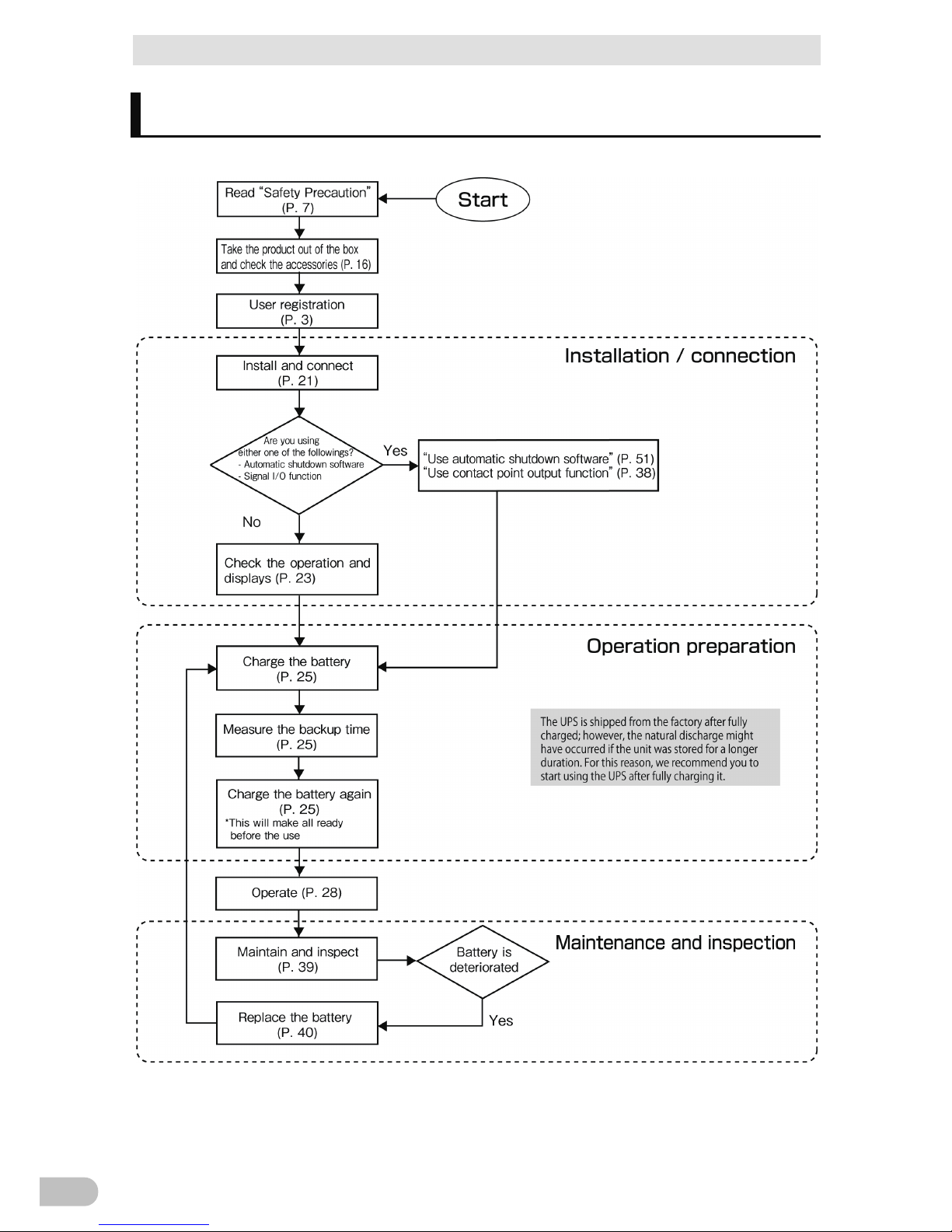
Procedure from installation to operation
Shows the procedure from installation to operation.
Page 5

Table of Contents
BW40T/BW55T/BW100T/BW120T
5
Table of Contents
Introduction .................................................................................................. 2
Procedure from installation to operation ................................................................ 4
Table of Contents ......................................................................................... 5
Safety Precautions ....................................................................................... 7
1 Preparation ........................................................................................ 16
1-1 Unpack the product ...................................................................................... 16
1-2 Check the accessories ................................................................................. 16
1-3 Name of Each Part ....................................................................................... 17
1-3-1 Button functions ................................................................................................................. 19
2 Installation and connection ................................................................ 20
2-1 Install ............................................................................................................ 20
2-2 How to connect the equipment ..................................................................... 21
2-2-1 Connecting equipment to the "power output” ..................................................................... 21
2-3 Check the Operation .................................................................................... 22
2-4 Battery charge .............................................................................................. 24
2-5 Initial Value Measurement for Backup Time ................................................. 24
2-6 Battery recharge ........................................................................................... 24
3 Operation of the Uninterruptible Power Supply (UPS) ....................... 25
3-1 Basic operations including running and stopping the unit ............................ 25
3-1-1 When "AC input" plug is connected to the commercial power supply in the power off ....... 25
3-1-2 How to start operation ........................................................................................................ 25
3-1-3 Action in the power failure .................................................................................................. 26
3-1-4 When recovered from the power failure ............................................................................. 26
3-1-5 How to stop the operation .................................................................................................. 26
3-1-6 Pausing the beep sound .................................................................................................... 26
3-2 Beep sound - How to see the display ........................................................... 27
4 UPS functions .................................................................................... 31
4-1 Suspending a beep ...................................................................................... 31
4-2 Self-diagnostic test ....................................................................................... 31
4-3 UPS setting utility software .......................................................................... 32
5 Measuring the backup time ............................................................... 33
Page 6

Table of Contents
BW40T/BW55T/BW100T/BW120T
6
5-1 How to measure backup time ....................................................................... 33
5-2 Estimated backup time ................................................................................. 33
6 Contact signal functions .................................................................... 35
6-1 Type of input and output signals .................................................................. 35
6-2 Pin assignment of USB/Contact port ............................................................ 36
7 Maintenance and Inspection.............................................................. 38
7-1 Checking the battery .................................................................................... 38
7-1-1 Life of battery (estimated replacement timing) ................................................................... 38
7-1-2 Methods for checking the battery ....................................................................................... 39
7-1-3 Guidelines for how often to check the battery (measure the backup time) ........................ 39
7-2 Replacing the battery ................................................................................... 39
7-2-1 How to replace a battery .................................................................................................... 41
7-3 Cleaning ....................................................................................................... 49
8 Using the UPS monitoring software ................................................... 50
8-1 The outline on the UPS monitoring software ................................................ 50
8-1-1 The supported OS of the UPS monitoring software ........................................................... 51
8-1-2 The functions list of the UPS monitoring software ............................................................. 52
8-2 How to use the UPS monitoring software ..................................................... 54
8-2-1 PowerAct Pro ..................................................................................................................... 54
8-2-2 Simple Shutdown Software ................................................................................................ 54
8-2-3 What is the Power Attendant Lite ....................................................................................... 54
8-2-4 The setting of the UPS monitoring software....................................................................... 55
9 References ........................................................................................ 57
9-1 Specifications ............................................................................................... 57
9-2 Dimensions .................................................................................................. 58
9-3 Circuit block diagram .................................................................................... 59
9-4 Related products .......................................................................................... 60
Page 7
Safety Precautions
BW40T/BW55T/BW100T/BW120T
7
Safety Precautions
Safety
Precautions
Describes important matters for safe use. Please read carefully
before installing or using the unit.
+ The symbols and respective meanings regarding the safety of this Instruction Manual are as
follows.
Danger
This symbol indicates that incorrect use may cause death or
severe injury.
Caution
This symbol indicates that incorrect use may cause serious
injury or property damage.
* Property damage represents consequential damage to property such as
houses, household effects, livestock and pets.
: This indicates prohibition (what you must not do.) For example, indicates
that disassembling is prohibited.
: This indicates obligation (what you must do.) For example, indicates that
you should ground to the earth.
However, even a symbol which indicates a caution could cause a severe result according to
situations.
Make sure of paying attention to these symbols containing critical indications.
Danger (product applications)
Never use this device for the following purposes, which require
extremely high reliability and safety.
* The UPS is designed and manufactured for FA (including PC) and OA equipment.
+ Applications such as medical equipment and systems that are directly related to
the safety of human life.
+ Applications that directly impact on human safety.
(E.g., applications that are directly related to the operation, driving, and control of
vehicles, elevators,etc.)
+ Applications that may cause serious social or public damage when they fail.
(E.g., applications for mission-critical computer systems, or trunk line
communication systems.)
+ Applications subject to vibration at all times, such as on a vehicle, or on a ship.
Caution (at installation and connection)
Carry the unit with taking the weight and balance into consideration,
and place it on a stable and sturdy place.
+ There is a risk of injury if the product falls or drops.
+ Unit mass: BW40T/BW55T: 4.5kg
BW100T/BW120T: 7.9kg
+ In a case of dropping the UPS, stop using the unit and immediately ask for the
inspection and repair.
For information about repair, contact Omron Electronics Repair Center.
Page 8
Safety Precautions
BW40T/BW55T/BW100T/BW120T
8
Keep the plastic package bags away from children.
+ Avoid the risk of a child playing with it to suffocate.
Make sure of connecting the "AC input" plug of this unit to a rated input
voltage (AC 100V) with the 50/60Hz frequency of the power outlet
(commercial power supply.)
+ Connecting to a power outlet (commercial power supply) with a different voltage
and frequency may cause a fire.
+ The UPS fail.
Stop the output by turning off the "Power" button on the UPS and pull
the power outlet off of "AC input" plug in a case of abnormality
(abnormal noise/odor.)
Connect "AC input" plug in a way it can be immediately pulled off of the
power outlet.
+ For safety, follow the above instructions when maintaining the connected
equipment also.
Do not connect the half-wave rectifier where the current flows only in a
half cycle of AC power supply, such as dryer and some solenoid valves.
+ Overcurrent may damage the Uninterruptible Power Supply.
Connect to the power outlet (commercial power supply) with the
following current capacity.
BW40T: 5.0A or higher
BW55T: 6.0A or higher
BW100T: 11.0A or higher
BW120T: 12.0A or higher
+ Power wiring can catch heat.
+ When the device with the maximum output capacity is connected, the following
current flow to the highest.
BW40T: 5.0A
BW55T: 6.0A
BW100T: 11.0A
BW120T: 12.0A
Make sure of setting up the earth connection (grounding.)
+ Check the shape of the power outlet's plug, and insert the UPS's "AC input" plug as
is.
Without an earth connection, the unit can fail or cause an electric shock due to the
electric leakage.
Do not disassemble, repair, or modify.
+ Electric shock or fire can occur.
Do not install in an undesignated direction.
+ There is a risk of injury if the product falls or drops.
+ Do not install in the direction other than specified; otherwise, the battery leakage
cannot be treated.
Do not use the UPS in an environment where the highest temperature
becomes more than 40°C.
+ The battery may deteriorate rapidly.
+ The UPS may fail or malfunction.
Page 9
Safety Precautions
BW40T/BW55T/BW100T/BW120T
9
The use and storage environment should be in the specification scope.
Do not install or store in the following places.
+ Do not store at the places where the humidity is lower than 10% or higher than
90%.
+ Do not use at the places where the ambient temperature is lower than 0 degrees
Celsius or higher than 40 degrees Celsius.
+ Do not use at the places where the humidity is lower than 25% or higher than 85%.
+ Other places not recommended for the use or storage are: enclosed spaces such
as tightly closed cabinet; places where flammable gas or corrosive gas is stored;
places exposed to direct sunlight; extremely dusty places; places subject to
vibration and impact; outdoor, etc.
+ It may cause fire.
Do not connect the devices that exceed the output capacity of the UPS.
You can add connected equipment with table taps, etc. However, do not
connect devices exceeding the current capacity of the taps.
+ The UPS detects overload and stops the output.
+ The table tap wiring may catch the heat and cause a fire.
Do not clip or bundle the cable while using.
+ Electric shock or fire can occur due to the cable damage or heat generation.
+ Stop using the UPS if the cable has damage and immediately ask for the repair.
For information about repair, contact Omron Electronics Repair Center.
All the accessories packaged together are available only when using the
UPS. Do not use it for any other devices.
+ Make sure of observing the followings for the safe use of equipment.
Do not block inlet/outlet ports (top, sides, and rear).
+ The internal temperature may rise, eventually damaging the UPS or deteriorating
the battery.
+ Keep the unit away from 5 cm or more from the wall.
Do not connect the voltage converter and insulating transformer to the
output side.
+ Overcurrent may cause failure or abnormal behavior on the Uninterruptible Power
Supply.
+ The Uninterruptible Power Supply (UPS) may fail or malfunction even when
connecting to the input side. Ensure to check the performance before use.
Do not connect devices that don't run on the commercial power supply.
Caution (for use)
Do not get it wet or put water on it.
+ Electric shock or fire can occur.
+ Stop using the unit, unplug the AC input cable from the outlet, and ask for the
inspection and repair in a case of the UPS got wet.
Page 10
Safety Precautions
BW40T/BW55T/BW100T/BW120T
10
For information about repair, contact Omron Electronics Repair Center.
Replace the battery as soon as the life ends, or discontinue the use of
the UPS.
+ Continue using it may cause a fire or electric shock due to the liquid leakage.
Ambient
temperature
Expected life * The table on the left shows the expected
life under the standard usage conditions,
not the guaranteed values.
25 degrees
Celsius
5 years
30 degrees
Celsius
3.5 years
40 degrees
Celsius
1.7 years
Wipe off the dust on the "AC input" plug and the power output outlet
occasionally.
+ It may cause a fire if the dust residues for a long time.
+ Stop all the connected equipment and the UPS and unplug the "AC input" plug
from the power outlet (commercial power supply) before wiping off the dust.
Do not use it in a sealed place, and do not cover it.
+ It may cause an abnormal heat or fire.
+ Depending on your environment, hydrogen gas may be generated from the battery,
which can cause burst or explosion. Keep ventilating around the UPS.
In a case of unusual noise or odor, smoke, or liquid leaks from inside,
immediately switch off the "Power" button of the UPS and unplug the
"AC input" plug from the power outlet (commercial power supply.)
+ It may cause a fire if continue using.
+ In a case of the UPS gets into above-mentioned, immediately stop using it, unplug
the AC input cable, and then ask for inspection/repair either for the dealer or
Omron Electronics Repair Center.
+ Use the UPS in a state where "AC input" plug can be unplugged from the power
outlet (commercial power supply) immediately when an abnormality occurs.
Do not touch the liquid leaked from inside.
+ Doing so may cause blindness or burns.
+ In case the liquid is in touch with an eye or skin, clean it off with a large amount of
clean water and see a doctor.
Do not place things on the top, nor drop heavy objects on it.
+ It may cause a fire due to the distortion or breakage of the case, or internal circuit
failure.
The UPS is equipped with a bypass output circuit that allows the unit to continue supplying power
to the connected devices even when the internal control circuit function stops due to a failure or
malfunction.
Stop the supply of "commercial power supply" or unplug the "AC input" plug if you want to stop
output.
+ Output continues even if all the displays on the display section is off.
+ The output ON / OFF operation with "Power" button on the front will disable.
Page 11
Safety Precautions
BW40T/BW55T/BW100T/BW120T
11
Caution (for maintenance)
Always turn off "Power" button of the UPS and unplug "AC input" plug
before starting the maintenance of the connected equipment.
+ The power output of the UPS does not stop even if the "AC input" plug is
unplugged during the Uninterruptible Power Supply (UPS) is in operation; the
output continues.
Do not disassemble, repair, or modify.
+ Electric shock or fire can occur.
Do not touch the liquid leaked from inside.
+ Doing so may cause blindness or burns.
+ In case the liquid is in touch with an eye or skin, clean it off with a large amount of
clean water and see a doctor.
Do not throw the UPS into the fire.
+ The lead battery contained may cause an explosion or the dilute sulfuric acid
leakage.
Do not insert metal objects in the "power output" outlet of the
Uninterruptible Power Supply (UPS.)
+ It may result in electric shock.
Keep out of any short-circuit between the battery connectors.
+ It may result in electric shock.
Cautions (for battery replace)
The battery pack should be replaced on a stable, flat place.
+ Hold the battery pack firmly to prevent it from dropping.
+ The drop of the battery pack may cause injury and burns due to liquid (acid)
leakage.
Do not use any other batteries than specified by our company.
It may cause fire.
+ Product models: Battery pack for replace: For BW40T/BW55T: BWB55T
For BW100T/BW120T: BWB120T
Do not replace the battery pack in a place where combustible gas exists.
+ Connecting the battery may bring to spark, causing explosion or fire.
Do not touch the liquid (dilute sulfuric acid) which leaks from the
battery.
+ Doing so may cause blindness or burns.
+ In case the liquid is in touch with an eye or skin, clean it off with a large amount of
clean water and see a doctor.
The battery should not be disassembled or modified.
+ Doing so could cause dilute sulfuric acid leak, which could cause blindness and
burns.
The battery should not be dropped or given any strong impact.
+ Dilute sulfuric acid may leak.
Page 12

Safety Precautions
BW40T/BW55T/BW100T/BW120T
12
Cautions (for battery replace)
Do not short the battery with metal objects.
+ That may cause electric shock, heat generation or burn injury.
+ Electric energy may remain even in a used battery pack.
Do not throw the battery in the fire or break it.
+ The battery may explode or leak dilute sulfuric acid.
Page 13

Safety Precautions
BW40T/BW55T/BW100T/BW120T
13
Compliance
Wait for several hours before start using the UPS when it has been
moved from a cold place to a warm place.
+ Moving the UPS from a cold place to a warm place can catch the moisture
(condensation) on it, which may fail by energizing it in the condition.
Charge the UPS as early as possible (for 12 hours or more) after
purchasing.
+ Not using the UPS for a long time after purchase can deteriorate the battery that
may result in dysfunction.
+ You can charge the battery by plugging a power outlet (commercial power
supply) into the "AC input" plug of the UPS.
When storing the UPS, charge the battery for 12 hours or more, and turn
off the power supply switch before storing it.
+ Even if the battery is not used, the battery is naturally discharged inside, and if it
is left for a long time, it goes into an over discharge state. In consequence, the
backup time may become shorter, or the battery may become unusable.
+ 25 degrees Celsius or below temperature is recommended for storing the UPS
for a long term.
Connect the UPS's "AC input" plug to the commercial power outlet for
12 hours or longer, when; the storage temperature is 25 degrees Celsius
or below, then after every six months, and the storage temperature is 40
degrees Celsius or below, then after every two months.
+ Turn off "Power" button of the UPS during storage.
Prevent the short circuit between the output lines of the UPS, or the
output line on the earth (grounding.)
+ The UPS may fail.
Do not plug in the UPS's "AC input" plug into the UPS's "power output"
outlet during the backup operation.
+ The UPS may fail.
Do not connect the page printer (such as a laser printer) to the UPS.
+ The page printer has a large peak current, which may result in the detection of
the excessive connection capacity.
Make sure of checking the operation first before using the UPS in
combination with the devices with large fluctuations in power frequency,
such as a household power generator.
+ The UPS automatically recognizes the input power frequency when the input
power is supplied. Connecting the UPS in a state where the input power
frequency is out of the specified value can cause the misrecognition of the power
frequency, which may result in the abnormal operation. It is okay for the power to
switch from the commercial power supply to the generator's power while the UPS
is running. However, adjust the frequency of the generator to match with the
commercial power supply.
Do not use the unit for the frequent backup operation.
+ Battery may deteriorate to the extent where the specified backup time cannot be
maintained.
Page 14

Safety Precautions
BW40T/BW55T/BW100T/BW120T
14
Compliance
Do not install or store the UPS in the place exposed to the direct
sunlight.
+ The internal battery may deteriorate due to the temperature surge that may result
in dysfunction.
Turn off the UPS power before switching off the commercial power
supply.
+ Once the commercial power supply stops, it switches to the backup operation. If
the frequency of backup operation becomes high, the battery life may be
significantly reduced.
When connecting the UPS with the inductive equipment, such as coils,
motors, transformers, make sure of checking the operation beforehand.
+ Some types of equipment may prevent the normal operation of the UPS due to
the inrush current, etc.
The UPS will not start up unless until the battery is connected.
+ Note that it also does not start in an over-discharge state or the state where the
degraded battery is connected.
Do not run the withstand voltage test.
+ The power supply input line contains the surge absorbing elements, which are
subject to destruction with the withstand voltage test.
+ Execute the insulation resistance within the range of DC 250V.
Make sure of all documents are attached to the UPS before transferring
or selling the UPS to a third party. The UPS shall comply all the
conditions stated in the attached documents.
+ This instruction manual contains the details instructions for assuring safety. Read
them carefully before start using the UPS.
Contact the store of purchase if you lost the instruction manual.
+ This unit uses lead acid batteries.
The lead acid batteries are precious recyclable resources. Please
cooperate recycling.
For more details about recycling, contact Omron Electronics
Replace Center, or
download the application form for the replacement service from our
website,
fill the required fields and send it to
our Replace Service Center.
Pb
Page 15

Safety Precautions
BW40T/BW55T/BW100T/BW120T
15
Details
About Daily Operation
+ The UPS 's "Power" button can remain ON (in operation) or be turned off every
time the connected system shuts down. You can follow your convenience.
However, turning off "Power" button is recommended when it is not in use for a
long time.
+ You can charge the battery by plugging a power outlet (commercial power
supply) into the "AC input" plug of the UPS.
About Closing Backup Operation
+ When the power failure state continues for an extended time, the battery starts
discharging, and the power output from the UPS stops. Shut down the PC by the
appropriate procedure (i.e., save the data) while the UPS continues supplying
power.
About Restart
+ If the battery discharges during the power failure, the UPS will stop. When the
UPS recovers from the power failure or other abnormal power states, it
automatically restarts and starts supplying power. When you do not want to
operate connected equipment, turn off "Power" button or other connected
equipment.
R
EFERENCE You can enable/disable automatic restart on "Setting" screen (P.30.)
Prepare for an unexpected circumstance, such as the data protection and system
redundancy.
+ The Uninterruptible Power Supply (UPS) may stop the output due to the
internal circuit failure.
Page 16

1 Preparation
1-1 Unpack the product
BW40T/BW55T/BW100T/BW120T
16
1 Preparation
1-1 Unpack the product
Open the package and take out the Uninterruptible Power Supply (UPS) and accessories.
1-2 Check the accessories
Check that all the accessories are accompanied in the package, and they have no
damage in appearance.
In case you find any defect or other problems, please contact your dealer immediately.
Precautions before Use
One
Warranty
One
Customer Registration Card
One
Guide to Customer Registration
One
3P - 2P conversion plug
One
Instructions for Labels Indicating Operating Condition
One
English Labels for Operation Panel
One
Battery Replaced Date Label
One
Connection Cable (USB)
One
Rubber Foot Cover for Horizontal Installation
One Set (four pieces)
Serial Label
One Set (four pieces)
UPS Replacement Service Brochure
One
About the Use of Shutdown Software
One
When using the UPS as a UL standards complied product, do not use 3P - 2P conversion plug.
<Customer Registration>
Fill out the necessary information on the attached customer loyalty registration card and
send us back within one month from the date of purchase.
User registration is accepted at our homepage
(http://www.omron.co.jp/ese/ups/regist/regist.html.)
Page 17
1 Preparation
1-3 Name of Each Part
BW40T/BW55T/BW100T/BW120T
17
1
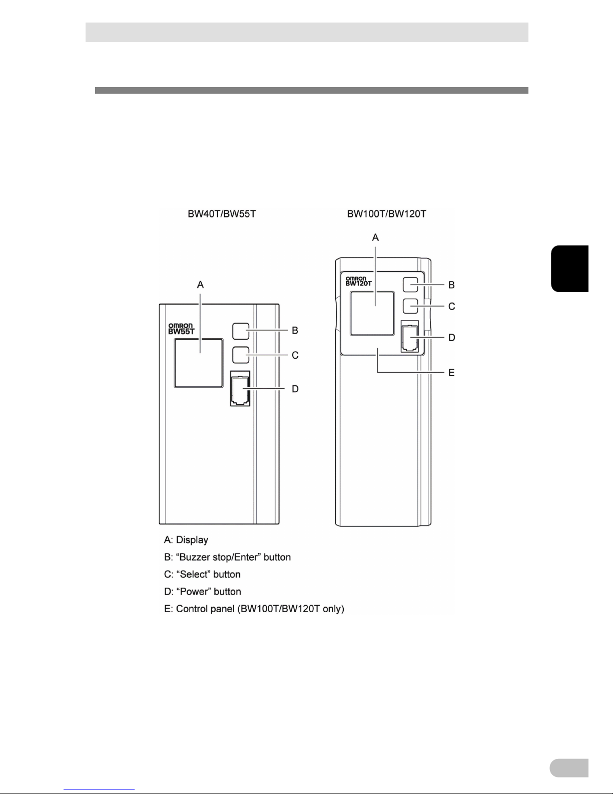
1-3 Name of Each Part
The followings list the names of the UPS parts.
Refer to "2Installation and connection” (P.20,) "3Operation of the Uninterruptible Power
Supply (UPS)” (P.25) and other sections for the details description of each function.
+ Front
Page 18
1 Preparation
1-3 Name of Each Part
BW40T/BW55T/BW100T/BW120T
18
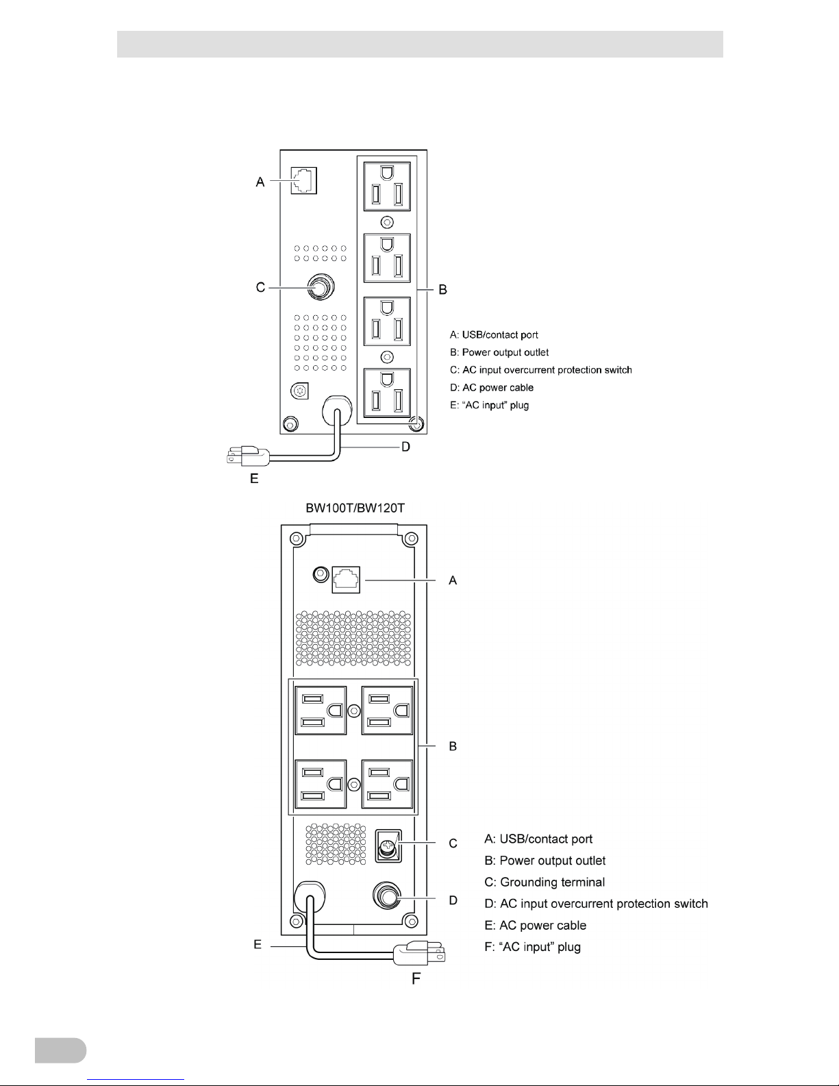
+ Back
BW40T/BW55T
Page 19
1 Preparation
1-3 Name of Each Part
BW40T/BW55T/BW100T/BW120T
19
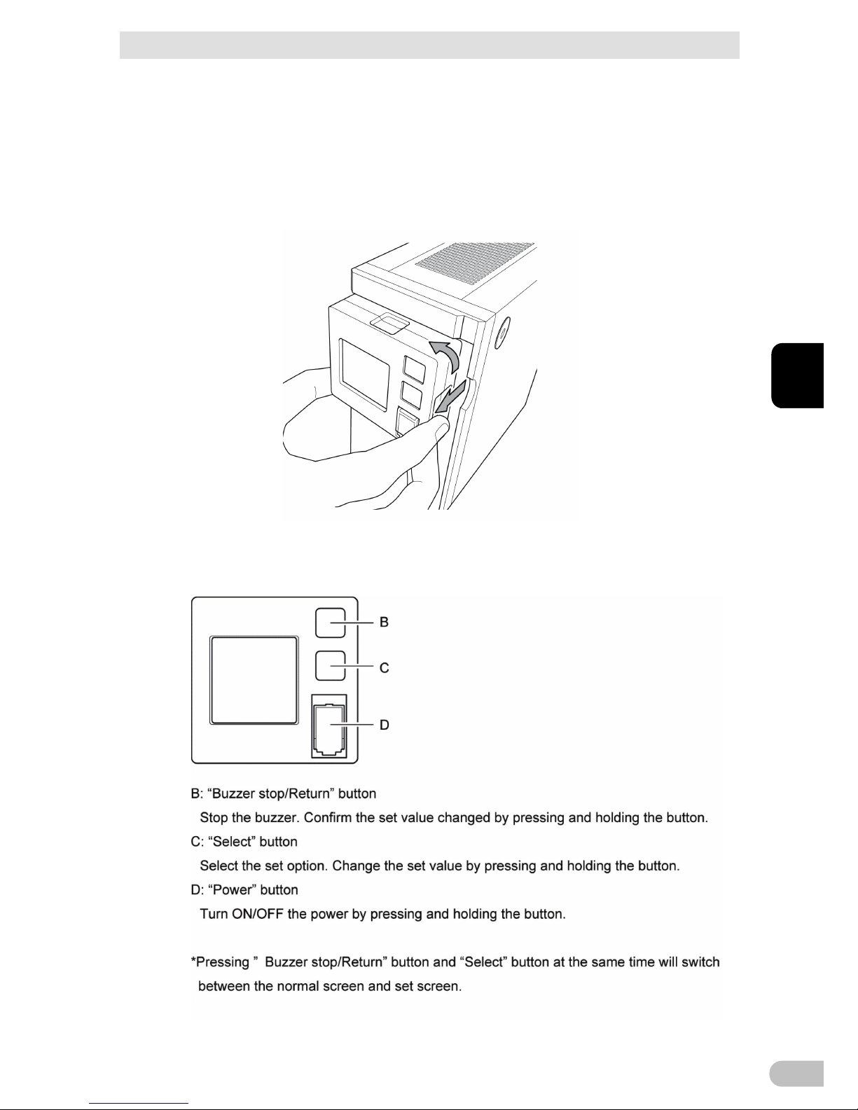
1
+ Rotation of the display part of the front panel operation
(BW100T/BW120T)
The operation display section can be rotated by 90 degrees by the placement whether it
is vertical or horizontal.
Pull out the operation display section, rotate it, and press it down.
*Do not rotate it 90 or higher degrees. Otherwise, the cord may be damaged.
1-3-1 Button functions
Page 20

2 Installation and connection
2-1 Install
BW40T/BW55T/BW100T/BW120T
20
2 Installation and connection
2-1 Install
Install the UPS.
Do not use any other ways than the correct installation direction specified in the figure
below.
Compliance
Product serial number is required whenever contacting us.
Check the product serial number on the top of the main body or the serial label on the
accessory.
Correct Direction of Installation
Watch your fingers and other parts of your body to not to be
pinched between the parts.
* Paste the rubber feet (for the horizontal installation) in the four corners
of the bottom surface.
Page 21

2 Installation and connection
2-2 How to connect the equipment
BW40T/BW55T/BW100T/BW120T
21
2
2-2 How to connect the equipment
2-2-1 Connecting equipment to the "power output”
1.
Disconnect all the "AC input" plugs of the equipment to back up, including PC,
Peripherals, from the power outlet (commercial power supply).
2.
Connect the equipment requiring backup to the UPS's "power output "outlet.
*When the UPS's output outlet is insufficient, purchase necessary equipment, such
as a table tap, and install it on the output outlet.
- The input plug shape of the connected device is 2P can also be connected to
the UPS's "power output "outlet.
The connection here cannot be used when the UPS is used as a UL compliant
product.
3.
Connect the UPS and PC with a connection cable when using Windows standard
UPS service, an automatic shutdown software for free download.
R
EFERENCE "8Using the UPS monitoring software” (P.50)
* This operation is not required when not using the automatic shutdown software.
Page 22

2 Installation and connection
2-3 Check the Operation
BW40T/BW55T/BW100T/BW120T
22
2-3 Check the Operation
Once the connection of equipment for backup with the UPS has been established, check
that the backup operation is normally running by the following procedure.
This operation check is to simulate the power failure that might occur by unplugging the
"AC input" plug from the power outlet (commercial power supply.)
+ How to view the display
* This screen shows "all lighted" state for explanation.
When the display is turned off, it turns on again by pressing a button.
1.
Press "Power" button on the UPS for at least 3 seconds.
It goes in the backup operation for about 10 seconds and then starts the selfdiagnostic test.
During the self-diagnosis, "FU" is displayed in "Detected Value.” The status display
icon is displayed as shown below.
When the self-diagnosis test ends normally, it switches to AC output from the
commercial power supply.
* When the battery voltage is low, the self-diagnostic test will not run; instead, the
operation starts directly with the output from the commercial power supply.
Status display
Description
Power ON
Normally operating
2.
Activate all connected devices (including the equipment connected to the service
outlet of the PC.)
* Please operate in a state where there is no problem even if the power of the
connected equipment stops in between.
The UPS is shopped after fully charged; however, the backup time may be
shorter due to the natural discharge at the time of first use. We recommend you
to start using the UPS after fully charging it.
Page 23

2 Installation and connection
2-3 Check the Operation
BW40T/BW55T/BW100T/BW120T
23
2
3.
Check the status display of the UPS in this state.
Status display
Power output outlet
Output the power (in a state where
connected equipment is conducted)
The display shows the
way as
mentioned
above ->
The operation is normal. Go to the procedure 4.
The display is
different from the
above mentioned
->
It is abnormal. The display shows either one of those
mentioned in “3
-3 How to Understand Beep Sound and
Display” (P.
27.)
Go to the procedure 4 after the treatment according to the
handling method.
4.
Pull out the AC input plug of the UPS from the power outlet (commercial power
supply.)
It goes in the backup operation state.
5.
Check the status display of the UPS in the backup operation state.
The display is different from
the above mentioned ->
It is abnormal. Turn
off "Power" button once.
-
When the display is according to "3
-3 How to
Understand Beep Sound and Display” (P.
27,) treat it
according to the handling method and
return to the
procedure 1 again.
-
If the UPS and connected equipment stop without
backing up at all, the battery might have required more
charging.
Connect the UPS's "AC input" plug to the power outlet
(commercial power supply) and charge the battery fo
r
over 12 hours, and then return to the procedure 4 again.
-
If the problem persists after attempting the above two
methods, contact OMRON Electronic Equipment
Customer Support Center.
6.
Connect "AC input" plug to the power outlet (commercial power supply) again.
The status display goes back to the original.
Status display
Description
Power ON
Normally operating
That’s all for the operation check.
The installation process has been completed.
The operation is normal. Go to the procedure 6.
Page 24

2 Installation and connection
2-4 Battery charge
BW40T/BW55T/BW100T/BW120T
24
2-4 Battery charge
The battery charging starts automatically by connecting the UPS's "AC input" plug to the
power outlet (commercial power supply.) The charging will complete in 12 hours
maximum.
*The UPS will charge both ON and OFF states.
The UPS is shipped from the factory after fully charged; however, the backup time may
be shorter due to the natural discharge at the time of first use. We recommend you to
start using the UPS after fully charging it.
Follow the operation in "3Operation of the Uninterruptible Power Supply (UPS)” (P.25)
when not performing “2-5 Initial Value Measurement for Backup Time.”
2-5 Initial Value Measurement for Backup Time
Measure the initial value of the UPS’s backup time in your environment, so it can be a
standard when inspecting the battery or deciding the setting value of the automatic
shutdown software.
R
EFERENCE "5.Measuring the backup time” -> (P. 33)
2-6 Battery recharge
The battery completely discharges after measuring the backup time. You need to
recharge before use.
*You can use the connected equipment while charging; however, the backup time will
shorten in a case of power failure occurs until the charging is completed.
In this case, the backup immediately starts the moment the power failure occurs just
after start charging.
REFERENCE "2-4Charging the Battery” (P. 24)
All the preparation for starting the operation has been completed.
Page 25

3 Operation of the Uninterruptible Power Supply (UPS)
3-1Basic operations including running and stopping the unit
BW40T/BW55T/BW100T/BW120T
25
3
3 Operation of the Uninterruptible
Power Supply (UPS)
3-1 Basic operations including running and
stopping the unit
3-1-1 When "AC input" plug is connected to the
commercial power supply in the power off
- Power output is stopped.
- Battery starts automatic charging.
3-1-2 How to start operation
1.
Press "Power" button for three or more seconds.
- During the self-diagnosis, "FU" is displayed in "Detected Value.” The status
display icon is displayed as shown below.
When the self-diagnosis test ends normally, it switches to AC output from the
commercial power supply.
- When the self-diagnosis test isn’t executed, it immediately switches to AC output
from the commercial power supply.
Status display
Power output outlet
Output the power (in a state where
connected equipment is conducted)
- The battery is charged automatically while running.
When the power button is OFF with AC input OFF
When the power button is OFF with AC input OFF
Page 26

3 Basic operations including running and stopping the unit
3-1 Basic operations including running and stopping the unit
BW40T/BW55T/BW100T/BW120T
26
3-1-3 Action in the power failure
- When a power failure or an abnormal input power occurs, the unit automatically
switches to the battery mode and continues the power output from the "power output"
outlet with the electricity sourced from the battery.
- In Battery mode, the following icons are displayed.
3-1-4 When recovered from the power failure
- While the power output is from the battery mode, the unit automatically returns to the
output from the commercial power supply as soon as it recovers from the power failure
or abnormal power. The battery starts automatic charging.
- Once the battery runs down completely, the UPS’s power output stops. Then, the UPS
automatically restarts and starts supplying power again the moment it recovers from
the power failure or other abnormal input power states. The consumed battery is
charged automatically.
R
EFERENCE You can enable/disable automatic restart on "Setting" screen (refer to P.
30.)
3-1-5 How to stop the operation
Press "Power" button for three or more seconds in power ON state.
- Power output stops.
- Even in power OFF state, the battery is automatically charged as long as the
commercial power supply is available.
3-1-6 Pausing the beep sound
The activated beep sound pauses by pressing "Stop buzzer/Enter" button.
R
EFERENCE You can enable/disable beep sound on "Setting" screen (P. 30.)
Page 27

3 Operation of the Uninterruptible Power Supply (UPS)
3-2Beep sound - How to see the display
BW40T/BW55T/BW100T/BW120T
27
3
3-2 Beep sound - How to see the display
○: Lighted ●: Extinguished : Blinking
No. Status display
Status
Display
Icon
Buzzer Output Charge Description Solution
1
None None OFF OFF
No AC input
Operation halted
2
None None OFF ON
AC input
"Power" button "off"
3 *1
None ON ON
"Power" button [on]
Normally operating
4
None ON
OFF
Dischar
ging
In the self-diagnosis test
5 *2
Intermitt
ent, at
4s
intervals
ON
OFF
Dischar
ging
Backup operation due to
power failure or AC input error.
Output stops if backup
operation is continued.
Process the termination of the
connected devices you are using,
and then stop the devices.
6
Intermitt
ent, at
1s
intervals
ON
OFF
Dischar
ging
(Same as above)
Output stops soon due to low
battery level.
Process the termination of the
connected devices you are using,
and then stop the devices.
7
None None OFF
OFF
Dischar
ging
Output stopped due to low
battery.
Charge the battery.
8
None None OFF (ON)
AC input error (over)
When the voltage is high: The
left digit only blinks
When the frequency is high:
The right digit only blinks
When both voltage and
frequency are high: Both blink
Use in the AC input voltage range
and frequency described in the
specification.
9
None None OFF (ON)
AC input error (under)
When the voltage is low: The
left digit only blinks
When the frequency is low:
The right digit only blinks
When both voltage and
frequency are low: Both blink
10
Continu
ation
0.5
second
Interval
ON
ON
Or,
Dischar
ging
Too many devices are
connected. The capacity rating
has been exceeded.
Output stops if the state
continues for a certain duration
Reduce the connected devices.
11
Success
ive
OFF
ON
Or,
Dischar
ging
Output stops due to exceeded
connection capacity
Turn OFF all the power switches on
the UPS and connected devices,
reduce the connected devices, and
then turn ON the "Power" button on
the UPS and connected devices.
12
Success
ive
OFF
ON
Or,
Dischar
ging
Output has stopped due to the
short circuit
Check that the AC input of any of
the connected devices is not shortcircuited and that connections did
not exceed the rated capacity.
13
Success
ive
ON
-
Abnormal operation or failure
has occurred
Turn OFF all the power switches on
the UPS and connected devices,
and turn ON only the "Power"
button on the UPS again. If the
displayed detail does not change,
ask for the repair as a problem is
suspected with the UPS. The
changes in the display content may
be due to the combination of
connected equipment. Contact
Electronic Equipment Customer
Support Center for any doubts.
14
Success
ive
OFF -
Stopped due to the abnormal
output voltage (over)
15
Success
ive
OFF -
Stopped due to the abnormal
output voltage (under)
16
ON OFF -
Charge stopped due to
abnormal charging voltage of
the battery (over)
Ask for the repair as a problem is
suspected with the UPS.
17
ON OFF -
Charge stopped due to
abnormal charging voltage of
the battery (under)
Page 28

3 Beep sound - How to see the display
3-2 Beep sound - How to see the display
BW40T/BW55T/BW100T/BW120T
28
18
ON OFF -
Abnormal internal temperature
occurred
This may be caused by the UPS's
ambient temperature surging.
Check the ambient temperature of
UPS. If the UPS temperature
exceeds 40 degrees Celsius, cool
down the ambient temperature.
Turn OFF all the power switches on
the UPS and connected devices,
and turn ON only the "Power"
button on the UPS again. Ask for
the repair as a problem is
suspected with the UPS if the
temperature is 40 degrees Celsius
or below.
19
None
Success
ive
ON -
An abnormality occurred in the
internal communication.
Turn OFF all the power switches on
the UPS and connected devices,
and turn ON only the "Power"
button on the UPS again. If the
displayed detail does not change,
ask for the repair as a problem is
suspected with the UPS.
20
Continu
ation
1
second
Interval
ON OFF
Abnormal battery temperature
occurred
Turn OFF all the power switches on
the UPS and connected devices,
and turn ON only the "Power"
button on the UPS again. If the
displayed detail does not change,
ask for the repair as a problem is
suspected with the UPS.
21
Success
ive
ON OFF UPS product life has ended. Replace the UPS.
22
Continu
ation
2
seconds
Interval
ON ON
Battery deterioration or
disconnection has been
detected.
(Alarm only; output continues)
Connect or replace the battery.
Get an optional replacement
battery, and you can replace the
battery on your own.
*1 Output voltage displays.
*2 Backup standard time displays.
The status display can be switched among each detected value with "Select" button.
The detected value transits as follows.
Page 29

3 Operation of the Uninterruptible Power Supply (UPS)
3-2Beep sound - How to see the display
BW40T/BW55T/BW100T/BW120T
29
3
How to view and set the setting screen
This operation is available in both the power ON and OFF.
1.
Pressing "Stop buzzer/Enter" switch and "Select" switch at the same time, the
screen switch to the Setting screen (the buzzer sounds).
2.
Press the "Select" switch to select the items you want to set.
3.
By selecting the setting option and pressing the "Select" switch for 2 to 3 seconds,
the setting options and set values turn from a lighted state to blinking state (if it
does not blink, repeat the step from the procedure 2.)
4.
Pressing the "Select" switch can change the setting value.
5.
Press the "Stop buzzer/Enter" switch for about 1 second to confirm the setting.
The switch turns from a lighted state to blinking state (if it does not blink, repeat
the step from the procedure 4.)
6.
Press the "Stop buzzer/Enter" switch and "Select" switch at the same time to
return to the normal screen (the buzzer sounds).
Page 30

3 Beep sound - How to see the display
3-2 Beep sound - How to see the display
BW40T/BW55T/BW100T/BW120T
30
List of setting options and values
Setting options Description Setting values
Buzzer
0: Disabled
1: Enabled (factory setting)
Auto restart
0: Disabled
1: Enabled (factory setting)
Self-diagnosis test
0: Disabled
1: Enabled (factory setting)
Input voltage sensitivity
1.2: Standard sensitivity
(Factory setting: 1)
3: High Sensitivity
Cold start
0: Disabled (factory setting)
1: Enabled
Battery life counter
0: Disabled
1: Enabled (factory setting)
Power button shutdown
0: UPS shutdown
(factory setting)
1: UPS + PC shutdown
Restart level
0-9: 0-90%
0: (factory setting)
Maximum Backup Time
0.1-9: 0.1-9 minutes *
(Factory setting: 0 second)
LCD auto-off
0: Always ON (factory setting)
1: Turned OFF after 30 seconds
2: Turned OFF after 3 minutes
Self-diagnosis test (manual) Run the self-diagnosis test
Battery life counter reset Resets the battery life counter
* Range of values
With period: SJ.1 - SJ.9 = Up to 54 seconds by 6 minutes.
Without period: SJ1 - SJ9 = Up to 9 minutes by 1 minute.
The setting utility allow to set up to 9999 minutes within 10 - 59 seconds by 1 second.
Page 31

4 UPS functions
4-1 Suspending a beep
BW40T/BW55T/BW100T/BW120T
31
4
4 UPS functions
4-1 Suspending a beep
You can suspend a beep by pressing and holding the Beep Stop/Select Button while a
beep is sounding.
4-2 Self-diagnostic test
This test performs a failure diagnosis on the UPS and performs an easy test to check for
battery deterioration.
Use the procedure below to check whether a circuit failure has occurred inside the UPS
and whether battery replacement is required.
1.
Connect your computer and other devices to the UPS and then turn on the power
button of the UPS.
2.
The self-diagnostic test starts automatically.
The Battery Mode starts for testing purpose. (No beep sounds.)
When the test is complete, the normal operation automatically starts.
3.
If the status indicator/battery replacement lamp blinks and the beeper sounds:
S
EE ALSO Follow the directions for the solutions described in “3-2Beep sound -
How to see the display (Page 27).”
Manual testing
1.
By pressing "Buzzer stop/Enter" button and "Scroll" button simultaneously, the
buzzer which sounds like 'p’ (continuous sound) will beep and the setting display
will appear.
2.
Press "Scroll" button, display of setting items change continuously [S11],
[S21],,,[C00].
3.
By choosing [C00] and pressing "Scroll" button for a long time, [C00] blinks. By
pressing "Buzzer stop/Enter" button, self-diagnostic test start and display [FU].
4.
As the test complete normally, [C00] stops blinking, and the self-diagnostic test is
complete.
5.
Press "Buzzer stop/Enter" button and "Scroll" button simultaneously. The buzzer
sounds like 'p' (continuous sound) and back to the normal screen.
If the battery is not fully charged, the self-diagnostic test is not executed immediately.
After charging is complete, it is automatically executed.
Page 32

4 UPS setting utility software
4-3 UPS setting utility software
BW40T/BW55T/BW100T/BW120T
32
4-3 UPS setting utility software
UPS setting utility software is software for various UPS settings. This software facilitates
various UPS setting changes.
For example) Possible to stop UPS without using monitoring software at the time of
power failure
->Set the “Maximum backup time setting.
[Items available]
(1) Complete beep stop
(2) Voltage sensitivity mode setting
(3) Cold start setting
(4) Maximum backup time setting
(5) Automatic self-diagnostic testing
(6) Startup delay time setting
(7) Startup battery charge capacity setting
For details, refer to the UPS utility software instruction manual.
UPS setting utility software and UPS setting utility software instruction manual can be
downloaded from our website
(http://www.omron.co.jp/ese/ups/support/download/download.html).
Page 33

5 Measuring the backup time
5-1 How to measure backup time
BW40T/BW55T/BW100T/BW120T
33
5
5 Measuring the backup time
5-1 How to measure backup time
1.
Connect the AC Input Plug of the UPS to a wall outlet (commercial power) and
charge it for approximately over 12 hours.
2.
Turn ON all connected device.
Turn ON devices connected to the AC outlet of your computer.
Operate them in a way in which it is allowable that power supply to the
connected devices stops.
3.
Disconnect the AC Input Plug of the UPS and measure the backup time.
Measure the time until the unit automatically stops and all displays disappear with
the plug disconnected.
5-2 Estimated backup time
The backup time varies depending on the capacity of connected devices.
After calculating the total capacity of connected devices, refer to the graph of the backup
time to obtain an estimation of the initial value of the backup time. (This is also applied to
checking the battery.)
1.
Unify the total capacity (power consumption) of connected devices to W (Watt).
For the indication of connected devices, check your computer and the rear of the
display.
There are 3 types of indication: VA (Volt·Ampere) indication, A (Ampere) indication,
and W indication.
Example 1) 100 VAC, 50/60Hz, 145 W
Example 2) 100 VAC, 50/60Hz, 1.8 A
Example 3) 100 VAC, 50/60Hz, 150 VA
For devices that use the VA or A indication,
convert the capacity into W. Multiply the value indicated on devices by the value in
the right table for conversion.
When the power factor is unknown, enter “1”. The power factor usually ranges
between 0.6 and 1.
Indication
Value
VA
W = VA× power factor
A
W = VA× power factor× 100
The backup time you measure for the first time after purchase is the "initial
value of the backup time.”
After charging is complete, it is automatically executed.
Page 34

5 Measuring the backup time
5-2 Estimated backup time
BW40T/BW55T/BW100T/BW120T
34
2.
Add the values converted into W to obtain the total capacity of the connected
devices.
Estimated backup time
Backup time-table
* These backup times are for reference only. Times may vary according to battery
life and external environmental conditions (temperature, etc.).
* The maximum value of the estimated backup time display is 99.9 minutes on
LCD.
Load/Type
20 40 50 60 80 100 120 150 180 200 210 240 250 270 300 330 340 400 500 600 610 700 720 730
BW40T
105 60 50 36 28 22 18 13 10 8 7 6 5.4 - - - - - - - - - - -
BW55T
105 60 50 36 28 22 18 13 10 8 7 6 5.4 5 4.5 4 3.6 - - - - - - -
BW100T
220 120 100 84 64 50 40 32 24 20 19 17 16.5 15 13 11.5 11 8 5 4.5 4.3 - - -
BW120T
220 120 100 84 64 50 40 32 24 20 19 17 16.5 15 13 11.5 11 8 5 4.5 4.3 4.2 4 3.6
Page 35

6 Contact signal functions
6-1 Type of input and output signals
BW40T/BW55T/BW100T/BW120T
35
6
6 Contact signal functions
The UPS can use USB/connection port as the contact signal.
When using as the contact signal, use a contact signal cable (type: BUC31) separately
sold.
* When using as USB, use the attached USB cable.
6-1 Type of input and output signals
The UPS has the following input signals and four kinds of output signals.
The output circuit consists of an open collector circuit using a photo coupler (a kind of
electronic switch).
Pin assignment and signal name of contact port
Signals
Descriptions
Input of backup stop signal (BS) The input signal for stopping the output of the
UPS
Backup Signal output (BU) Stays ON during backup operation at a power
failure.
Trouble Signal output (TR) Goes ON when an internal failure of the UPS
occurs or when the battery life counter expires.
Battery Replacement Signal
output (WB)
Goes ON when the self-diagnostic test
determines that battery replacement is necessary
due to deterioration or when the battery life
counter goes off-scale.
Page 36

6 Contact signal functions
6-2 Pin assignment of USB/Contact port
BW40T/BW55T/BW100T/BW120T
36
6-2 Pin assignment of USB/Contact port
●Pin assignment and signal name of contact port
IO Signal name Contact port
IO
It is not used as USB D+/contact signal.
1
IO
It is not used as USB D-/contact signal.
2
O
Backup Signal output (BU)*
3
-
COMMON (COM)
4
I
It is not used as USB-Vbus/contact signal.
5
I
Input of backup stop signal (BS)
6
O
Trouble Signal output (TR)*
7
O
Battery Replacement Signal output (WB)*
8
* Factory default setting By setting utility, it is possible to change the combination of
output signals and to allocate the battery LOW signal output (BL). Also, it is possible
to set the time until output stopped by backup stop signal (BS) . You can download the
setting utility for free from our homepage.
Note: Dealing with unused signal cables
To prevent the malfunction, take measures such as to cut or isolate stripped wires
(exposed conductive part) to prevent to contact.
Page 37

6 Contact signal functions
6-2 Pin assignment of USB/Contact port
BW40T/BW55T/BW100T/BW120T
37
6
-Signal terminal specifications-
Signal output
(BU/BL/TR/WB)
Type of
signals
Isolated output through a photo
coupler
Rated
Voltage: 35V or less Maximum
current: 50mA
Input of backup stop signal
(BS)
Signal
condition
Input Voltage: 5V-15V
Input circuit Isolated input by a photo coupler
Page 38

7 Maintenance and Inspection
7-1 Checking the battery
BW40T/BW55T/BW100T/BW120T
38
7 Maintenance and Inspection
Caution (maintenance)
When maintaining the connected equipment, turn OFF the
power switch and disconnect the AC input plug.
The backup function continues to supply power from the power output
receptacles while the UPS is operating, even when the AC input plug is
disconnected.
Do not disassemble, repair, or modify the unit.
Doing so may cause an electric shock or a fire.
If fluid leaks from the unit, do not touch the fluid.
Doing so may cause blindness or burns.
If the fluid contacts your eyes or skin, wash it out with lots of clean water
and consult your doctor.
Do not throw the unit into fire.
The lead battery in the unit may explode, or leak dilute sulfuric acid.
Do not insert metal objects into the power supply output
receptacles of the UPS.
Doing so may result in electric shock.
Do not insert any metal in a battery connector.
Doing so may result in electric shock.
7-1 Checking the battery
The sealed lead battery used in the unit has a limited life.
The life varies depending on your storage/use environment and backup frequency.
The nearer the end of the life is, the more rapidly deterioration proceeds.
7-1-1 Life of battery (estimated replacement timing)
Ambient
temperature
Life of battery
25 degrees
Celsius
5 years
30 degrees
Celsius
3.5 years
40 degrees
Celsius
1.7 years
Page 39

7 Maintenance and Inspection
7-2 Replacing the battery
BW40T/BW55T/BW100T/BW120T
39
7
7-1-2 Methods for checking the battery
There are two methods for checking the battery.
- Perform a self-diagnostic test. (See page 31.)
- Measure the backup time. (See page 33.)
By measuring the backup time, the battery life can be determined more accurately.
If the measured value is less than half the value of the "initial value of the backup time,"
replace the battery.
* When you compare the "initial value of the backup time" you measured and the current
backup time, make the capacity of devices connected to the UPS same as when you
measured the initial value to make judgment accurately
7-1-3 Guidelines for how often to check the battery
(measure the backup time)
Ambient
temperature
Check once every six
months
Check once a month
25 degrees
Celsius
For the first 3 years after
purchase
When 3 or more years
have passed since
purchase
30 degrees
Celsius
For the first 1.5 years
after purchase
When 1.5 or more years
have passed since
purchase
7-2 Replacing the battery
The battery can be replaced either while the unit is stopped (power supply output
stopped) or while it is in operation (outputting power supply).
* The battery deteriorates even if it is stored. The higher the temperature is, the
shorter the life becomes.
After charging is complete, it is automatically executed.
Caution
When the unit is used in compliance with UL standards, do not replace the battery
while in operation (while power is being output). Replacing the battery while in
operation does not comply with UL standards. Make sure to stop the operation of
the unit before replacing the battery.
* When replacing the battery, stop the connected devices, turn OFF the power
switch of the UPS, and disconnect the AC input plug from the wall.
* If an input power supply error such as a power failure occurs when replacing the
battery while in operation, backup cannot be performed and output stops
* Do not replace the battery during backup operation. Output will stop.
Page 40

7 Maintenance and Inspection
7-2 Replacing the battery
BW40T/BW55T/BW100T/BW120T
40
Caution (for battery replacement)
Perform replacement on a stable and flat place.
Handle the battery carefully not to drop it.
Not doing so, could cause blindness or burns by the leaked fluid (dilute
sulfuric acid).
Do not use other than the batteries specified by our company.
It may cause fire.
Product model: BWB55T (Replacement battery pack for BW40T /
BW55T)
BWB120T (Replacement battery pack for BW100T / BW120T)
Do not replace the battery pack in a place where combustible
gas exists.
Connecting the battery may bring to spark, causing explosion or fire.
Do not touch the liquid (dilute sulfuric acid) which leaks from
the battery.
Doing so may cause blindness or burns.
If the fluid contacts your eyes or skin, wash it out with lots of clean water
and consult your doctor.
The battery should not be disassembled or modified.
Doing so could cause dilute sulfuric acid leak, which could cause
blindness and burns.
The battery should not be dropped or given any strong impact.
Dilute sulfuric acid may leak.
Do not short the battery with metal objects.
That may cause electric shock, heat generation or burn injury.
Electric energy may remain even in a used battery.
Do not throw the battery in the fire or break it.
The battery may explode or leak dilute sulfuric acid.
● This unit uses lead-acid batteries.
The lead-acid batteries are precious recyclable resources. Please
cooperate recycling.
For information on recycling, please contact the replacement service
center of OMRON, otherwise after downloading and filling out the
replace service application from our homepage, send it to our
replacement service center.
Pb
Page 41

7 Maintenance and Inspection
7-2 Replacing the battery
BW40T/BW55T/BW100T/BW120T
41
7
7-2-1 How to replace a battery
- BW40T/BW55T
* Work carefully not to slide and fall the unit.
1.
Lay it slowly so that the left side of the unit is upward.
2.
both hands put on the battery cover and slide it above to remove while putting the
nail plate on the lower of the cover.
Page 42

7 Maintenance and Inspection
7-2 Replacing the battery
BW40T/BW55T/BW100T/BW120T
42
3.
Holding the battery with your right hand and grabbing the battery cable (red)
connector with your left hand, pull it out from the battery connector.
*When it is difficult to pull it out, because of tight connection, pull it out while
rocking the connector part back and forth.
Then, grabbing the battery cable (black), pull it out from the battery connector.
4.
Remove the battery having the label.
Remove the battery with both hands while being careful not to drop it.
Page 43

7 Maintenance and Inspection
7-2 Replacing the battery
BW40T/BW55T/BW100T/BW120T
43
7
5
Insert the two connectors of the battery cables until clicking.
Hold the battery with your right hand and insert the connector of the battery and
battery cable (red) to the plus terminal with your left hand.
Then, insert the connector of the battery cable (black) to the negative terminal.
●Replacement battery pack
For BW40T / BW55T: Model BWB55T
6.
Fit the groove of the battery cover to the unit and slide it to attach it.
7.
Reset the battery life counter.
* Refer to the next page for reset the buttery life counter.
Page 44

7 Maintenance and Inspection
7-2 Replacing the battery
BW40T/BW55T/BW100T/BW120T
44
Make sure to reset the battery life cycle counter right after replacing the
battery.
If you do not reset the battery life counter, a battery deterioration alarm may
occur earlier than the expected battery life.
<When replacing it while [the AC input] plug is connected to a wall outlet>
1. By pressing "Buzzer stop/Enter" button and "Scroll" button simultaneously, the buzzer
which sounds like 'p’ (continuous sound) will beep and the setting display will appear.
2. Press "Scroll" button, display of setting items change continuously [S11], [S21],,,[C00].
By choosing [C00] and pressing "Scroll" button for a long time, [C00] blinks. By
pressing "Buzzer stop/Enter" button, self-diagnostic test start and display [FU]. As the
test complete normally, [C00] stops blinking.
3. Press "Scroll" button again, [C01] is displayed. Press "Scroll" button for a long time,
[C01] is blinked.
4. Press "Buzzer stop/Enter" button for a long time. The buzzer which sounds like 'p’
(continuous sound) will beep and the battery life counter will be reset. After finishing
blinking [C01], the reset is complete.
5. Press "Buzzer stop/Enter" button and "Scroll" button simultaneously. The buzzer which
sounds like 'p’ (continuous sound) will beep and the screen will go back to normal.
<When replacing it while [the AC input] plug is not connected to a wall outlet>
Connect [the AC input] plug to a wall outlet and do the above operation No. 1,3,4,5.
Write the battery replacement date on the included battery replacement date
label, and attach the label on the visible place.
Page 45

7 Maintenance and Inspection
7-2 Replacing the battery
BW40T/BW55T/BW100T/BW120T
45
7
- BW100T/BW120T
* Work carefully not to slide and fall the unit.
1.
Lay it slowly so that the left side of the unit is upward.
2.
Pull the front cover towards you to remove it by hooking a finger.
*Don’t twist the cable and put the cable between the battery while taking the
front cover off. Doing so will cause disconnection.
Page 46

7 Maintenance and Inspection
7-2 Replacing the battery
BW40T/BW55T/BW100T/BW120T
46
3.
Slide it by holding the protruding portion of the plate cover to the right (1) and pull
it towards you (2) to remove it.
*If lay the front cover aside, detach the cable from the catch.
4.
Remove the battery pack by pulling the tapes in its both sides.
Page 47

7 Maintenance and Inspection
7-2 Replacing the battery
BW40T/BW55T/BW100T/BW120T
47
7
5.
Insert the new battery pack. Securely push the battery pack until the connector on
the rear of the battery pack is connected to the unit.
● Battery pack for replacement
For BW100T / BW120T: Model BWB120T
You may hear a “pop” sound when you connect the battery, but this sound is not
abnormal.
6.
Attach the metal cover to the unit (1) and slide it the left (2) to fix it.
*If you detach the cable from the catch, put the cable in the catch.
Page 48

7 Maintenance and Inspection
7-2 Replacing the battery
BW40T/BW55T/BW100T/BW120T
48
7.
Attach the right side of the front cover to the unit (1), and push the left side to fix it
to the unit (2).
8.
Reset the battery life counter.
Be sure to reset the battery life counter after replacing the battery.
If you do not reset the battery life counter, a battery deterioration alarm may
occur earlier than the expected battery life.
<When replacing it while [the AC input] plug is connected to a wall outlet>
This operation is available in both the power ON and OFF.
1. By pressing "Buzzer stop/Enter" button and "Scroll" button simultaneously, the buzzer
which sounds like 'p’ (continuous sound) will beep and the setting display will appear.
2. Press "Scroll" button, display of setting items change continuously [S11], [S21],,,[C00].
By choosing [C00] and pressing "Scroll" button for a long time, [C00] blinks. By
pressing "Buzzer stop/Enter" button, self-diagnostic test start and display [FU]. As the
test complete normally, [C00] stops blinking.
3. Press "Scroll" button again, [C01] is displayed. Press "Scroll" button for a long time,
[C01] is blinked.
4. Press "Buzzer stop/Enter" button for a long time. The buzzer which sounds like 'p’
(continuous sound) will beep and the battery life counter will be reset. After finishing
blinking [C01], the reset is complete.
5. Press "Buzzer stop/Enter" button and "Scroll" button simultaneously. The buzzer which
sounds like 'p’ (continuous sound) will beep and the screen will go back to normal.
<When replacing it while [the AC input] plug is not connected to a wall outlet>
Connect [the AC input] plug to a wall outlet and do the above operation No. 1,3,4,5.
Write the battery replacement date on the included battery replacement date
label, and attach the label on the visible place.
Page 49

7 Maintenance and Inspection
7-3 Cleaning
BW40T/BW55T/BW100T/BW120T
49
7
7-3 Cleaning
1.
Cleaning the UPS
Moisten a soft cloth with water or detergent, squeeze it tightly, and wipe the
product lightly
Do not use chemicals such as thinner and benzene. They cause deformation or
discoloration.
2.
Removing dust from the AC input plug, power supply output receptacles of the
UPS
Stop all the connected devices and the UPS and disconnect the AC input plug
from a wall outlet (commercial power).
Then, remove dust with a dry cloth and connect again.
SEE ALSO Connecting the equipment “2-2How to connect the equipment” Page21
Page 50

8 Using the UPS monitoring software
8-1 The outline on the UPS monitoring software
BW40T/BW55T/BW100T/BW120T
50
8 Using the UPS monitoring software
When using the UPS monitoring software, connect and set as the followings.
8-1 The outline on the UPS monitoring software
When an input power supply abnormality (power failure, etc.) occurs, UPS monitoring
software can be used for shutting down connected computers. According to usage,
download and use necessary software from our home page:
(http://www.omron.co.jp/ese/ups/support/download/download.html). Refer to the following
table for the response situation for OS.
Notes
When manually starting during the scheduled operation using the UPS
monitoring software
To manually start up this unit after it has been stopped by a scheduled operation,
turn OFF the power switch and turn it back ON again. To manually stop the unit
during the scheduled operation, turn OFF the power switch.
Under the setting of auto stop the UPS after OS closing processing,
when the power is restored while auto shutdown processing is being
performed
If a power failure occurs and then the power is restored while auto shutdown is still
in progress, UPS output will stop temporarily after the set time elapses. After
shutdown is finished, do not turn on the computer until the UPS has finished
restarting.
Page 51

8 Using the UPS monitoring software
8-1 The outline on the UPS monitoring software
BW40T/BW55T/BW100T/BW120T
51
8
8-1-1 The supported OS of the UPS monitoring software
Compatible OSs
Communication
method
UPS monitoring software
Windows 10
Windows Server 2016
Windows Storage Server 2016
Windows 8.1
Windows 8
Windows Server 2012 R2
Windows Storage Server 2012 R2
Windows Server 2012
Windows Storage Server 2012
Windows 7
Windows Vista
(Ultimate/Business/Home Premium/Home
Basic)
Windows Server 2008 R2
Windows Storage Server 2008 R2
Windows Server 2008
Windows Storage Server 2008
Serial (USB 1.1)
Power Attendant Lite
PowerAct Pro
Simple Shutdown
Software*2
Windows Server2003
Windows Server2003 x64 Editions
Windows XP
Windows XP Professional x64 Edition
Serial (USB 1.1)
PowerAct Pro
Simple Shutdown Software
Linux
Cent OS Ver.7.x/Ver.6.x/Ver.5.x
Red Hat Linux Ver.7.x/Ver.6.x/Ver.5.x
Asianux Server 3
Serial (USB 1.1)
PowerAct Pro*1
Simple Shutdown
Software*1*4
macOS 10.12
Mac OS X
v10.11/v10.10/v10.9/v10.8/v10.7/v10.6/v10.5
Mac OS X Server
v10.11/v10.10/v10.9/v10.8/v10.7/v10.6/v10.5
Serial (USB 1.1) Power Attendant Lite
Serial (USB 1.1) PowerAct Pro*3
*1 Files cannot be automatically saved.
*2 Windows Storage Server 2008 R2/Windows Storage Server 2008 are not supported.
*3 PowerPC version is not supported When using macOS 10.12/Mac OS X 10.11 and Mac OS X Server v10.11 in
Ver.4.7, it is necessary to set OS. For details, refer to our homepage.
*4 Cent OS Ver.6.x、Red Hat Linux Ver.5.x、Asianux Server 3 is not supported.
Page 52

8 Using the UPS monitoring software
8-1 The outline on the UPS monitoring software
BW40T/BW55T/BW100T/BW120T
52
8-1-2 The functions list of the UPS monitoring software
●Standard support ○Optional support ▲, Partial limitation
Soft name
Descriptions
General use (single
function, stand-
alone)
Use for network management
(High function, supporting network)
Simple Shutdown
Software
PowerAct
Pro
PowerAttendantLite
Functions
of softs
Auto shutdown
● ● ●
UPS monitoring (operating
status)
- ● ●
UPS monitoring (data)
- ● ●
Pop-up notification
- ● ●
Shutdown OS in hibernate.
- ● ●
Auto file save - ●
-
Schedule Action
- ● ●
UPS setting change
- ● ●
External command execution
● ● ●
Event log save
- ● ●
Datalog save
- ● ●
Linked shutdown
- ● ●
Redundant power supply
support
- ● -
Remote UPS management
- ● ●
Mail send - ●
-
Telnet connection
- ● ●
SYSLOG support
- ● -
* This function is available only for windows. Mac and Linux are NOT available.
Page 53

8 Using the UPS monitoring software
8-1 The outline on the UPS monitoring software
BW40T/BW55T/BW100T/BW120T
53
8
With the UPS monitoring software, the following functions can be used.
Auto shutdown The computer can be shut down automatically when a problem occurs
with the power supply.
UPS monitoring (operating status) The operating status of the UPS can be monitored (in Commercial Power
Mode/Battery Mode).
UPS monitoring (data) Monitoring can be performed for input voltage value, connection capacity,
battery capacity, etc.
Pop-up notification When a problem such as a power failure occurs, a pop-up window that
shows the details of the problem can be displayed.
Shutdown when OS is inactive Shutdown can be performed when the computer is in an inactive state.
The operating status is retained at shutdown in inactive
state, so operation details are not lost.
Auto file save Files such as open Word and Excel documents are automatically saved
at shutdown.
Schedule operation
Schedule settings can be made for UPS stop/start.
UPS setting change UPS settings (beep ON/OFF, etc.) can be changed. Items that can be set
vary according to the UPS.
External command execution By executing commands at shutdown, items such as application
programs can be launched
Event log save Information of events that occur on the UPS (power supply problems,
setting changes, occurrences of failure, etc.) are saved
as a log.
Datalog save Data of input/output voltage value, connection capacity, etc. are
periodically saved as a log (the save frequency can be set).
Coordinated shutdown When a problem occurs with the power supply, multiple computers
connected to the UPS can coordinate to perform auto
shutdown.
Redundant power supply support Two or more UPS can be connected to computers equipped with
redundant power supply. Shutdown is not performed when a power
supply problem affects only one of the units. Shutdown is performed only
when a power supply problem occurs with both UPS, so the system’s
operating rate is improved.
Remote UPS management
The UPS can be managed remotely from a computer on the network.
Mail send When a problem such as a power failure occurs, a notification email
describing the problem can be sent to the system administrator.
Telnet connection Settings such as shutdown parameters can be made via the Telnet
connection.
SYSLOG support
UPS management information can be recorded in SYSLOG.
Page 54

8 Using the UPS monitoring software
8-2 How to use the UPS monitoring software
BW40T/BW55T/BW100T/BW120T
54
8-2 How to use the UPS monitoring software
8-2-1 PowerAct Pro
The included “PowerAct Pro” UPS monitoring software allows you to perform shutdown
processing of your PC when a power failure occurs. It is possible to shut down multiple
computers on the network. Also, you can perform the desired operation by setting the
automatic start/stop of the battery mode operation based on the scheduled setting.
References
Set the time from when a power outage occurs until PC is shut down as to complete
within the backup time measured by “5-1 How to measure backup time” on Page 33.
For details, see the manual for the above software.
8-2-2 Simple Shutdown Software
“Simple Shutdown Software” allows you to automatically shut down your PC when a
power failure occurs.
For details, see the manual for the above software.
Visit our website to download the manual for this software:
http://www.omron.co.jp/ese/ups/support/download/download.html
8-2-3 What is the Power Attendant Lite
Using the included “PowerAct Pro” UPS monitoring software allows you to automatically
shut down your computer when a power failure occurs.
Also, you can perform the desired operation by setting the automatic start/stop of the
battery mode operation based on the scheduled setting.
For details, see the manual for the above software.
Visit our website to download the manual for this software:
http://www.omron.co.jp/ese/ups/support/download/download.html
Page 55

8 Using the UPS monitoring software
8-2 How to use the UPS monitoring software
BW40T/BW55T/BW100T/BW120T
55
8
1.
Connect the UPS to a computer.
Cable: Included connection cable (USB)
2.
Install the included “PowerAct Pro,” “Simple Shutdown Software” or “Power
Attendant Lite” to the PC you want to shut down.
Installation method: See the manual for the above software.
Visit our website to download the manual for this software:
http://www.omron.co.jp/ese/ups/support/download/download.html
8-2-4 The setting of the UPS monitoring software
Scheduled operation using the UPS monitoring software
When performing scheduled operation in which the UPS is stopped and a device such as
a breaker is used to stop the UPS at the same time that commercial power stops, specify
a period of no more than 3 months for the start of the next operation.
If you specify a period longer than 3 months, the internal timer is reset and the scheduled
operation does not start.
Note that this period reduces to approximately half when the battery is dead.
If a period of 3 months is exceeded, you start operation by supplying commercial power
and pressing the power button. However, if the battery is dead, you may not be able to
start operation. In this case, replace the battery according to “7-2Replacing the battery"
on page39.
Start of operation in scheduled operation using the UPS monitoring software
To manually start up this unit after it has been stopped by a scheduled operation, turn
OFF the power button and turn it back ON again.
To stop the unit when it is in operation, turn OFF the power switch.
Page 56

8 Using the UPS monitoring software
8-2 How to use the UPS monitoring software
BW40T/BW55T/BW100T/BW120T
56
Auto restart after OS closing processing using the UPS monitoring software
When a power failure occurs, certain PCs (*1) automatically restart immediately after the
OS is shut down by auto shutdown.
In this case, the UPS stops during or after the restart of the PC, which may damage files
and the hard disk.
You can avoid this phenomenon by disabling POWER MANAGEMENT in the BIOS
settings of the PC.
*1) Certain PC: It is known that this phenomenon occurs for MICRON's Millennia Mme.
Precautions when “setting the UPS to stop automatically” after OS shutdown
If, after a power failure occurs, the power is restored while auto shutdown processing is
being performed, UPS output stops once after the set time elapses. After shutdown
processing is complete, do not turn ON the computer until the UPS has finished
restarting.
Page 57

9 References
9-1 Specifications
BW40T/BW55T/BW100T/BW120T
57
9
9 References
9-1 Specifications
Model
BW40T
BW55T
BW100T
BW120T
Method
Operation method
Full-time commercial power supply method
method
Natural air cooling
Connectable devices
PC, display, and peripherals
Input
Rated input voltage
AC100V
Startup voltage range and input
voltage range
Standard sensitivity setting 86±3 to 114±3 VAC
High voltage sensitivity setting 95±3 to 108±3 VAC
Input Frequency
50/60Hz±4Hz
Maximum current
5A
6A
11A
12A
Phase
Single-phase, two-wire (grounded)
Input plug
NEMA5-15P
Input protection
Reset-type over current protection
Input protection capacity
10A
15A
Output
Output capacity (shared
maximum) *1
400VA/250W 550VA/340W 1000VA/610W 1200VA/730W
Output voltage (In Commercial
Power Mode)
Input voltage through output
Output voltage (In Battery Mode)
AC100V±6%
Output frequency (In
Commercial Power Mode)
Input frequency through output
Output frequency (In Battery
Mode)
50/60Hz±0.1Hz
Phase
Single-phase, two-wire (grounded)
Output waveform
(In Commercial Power Mode/
Battery Mode)
Sine wave/sine wave
Waveform distortion rate
(In Battery Mode)
25% or less
Output receptacle
NEMA 5-15R x 4 receptacles
Switching time
10 msec. max
Battery
Backup time (*2)
5.4 min. or
more
3.6 min. or
more
4.3 min. or
more
3.6 min. or
more
Type
Compact sealed lead battery
Battery life expectancy
5 years (long operating life) *At ambient temperature of 25
Battery capacity (V/Ah/quantity)
12 VDC / 7.8Ah / 1
12 VDC / 7.8Ah / 2
Charging time
12 hours
Environ
ment
Operating environment
temperature/humidity
0 to 40 degrees Celsius / 25 to 85% RH (with no condensation)
Storage environment
temperature/ humidity
-15 to 40 degrees Celsius / 10 to 90% RH (Store with battery
fully charged and with no condensation)
Lightening surge protection function
Available
Dimensions (W x D x H) *3
90 x 291 x 165 mm
85 x 342 x 235 mm
Page 58

9 References
9-2 Dimensions
BW40T/BW55T/BW100T/BW120T
58
Weight of unit
4.5 kg
7.9 kg
Internal power consumption Norma/Max
10W/20W (under no load)
15W/25W (under lated load)
15W/35W (in no-load)
30W/45W (under lated load)
Communication interface
USB / contact
Noise regulation
VCCI Class B
Safety standard compliance
UL1778/CE
Noise
40 dB max.
*1: Make sure that both the VA value and the W value of the load capacity connected to the UPS
are within the range specified here.
*2: At ambient temperature of 25 degrees Celsius and with battery in initial state.
*3: The height does not include the height of rubber feet.
9-2 Dimensions
Unit: mm
<BW40T/BW55T>
Page 59

9 References
9-3 Circuit block diagram
BW40T/BW55T/BW100T/BW120T
59
9
<BW100T/BW120T>
9-3 Circuit block diagram
Page 60

9 References
9-4 Related products
BW40T/BW55T/BW100T/BW120T
60
9-4 Related products
For BW40T/BW55T
For BW100T/BW120T
Replacement battery pack
BWB55T
BWB120T
Bracket
BWP55T
BWP120T
USB cable
BUC30
Contact signal cable
BUC31
Page 61

NUD-D-17063A
No part or whole of this manual may be reproduced without permission.
The contents of this manual are subject to change without notice.
 Loading...