

Omron A1000-FIV2050-SE, A1000-FIV2010-SE, A1000-FIV2100-SE, A1000-FIV1010-SE, A1000-FIV1020-SE User Manual
...Page 1
»
1 0 0 % e x p e c t a t i o n m a t c h
»
1 0 ye ar s li fe ti me
»
1 i n 10 ,0 0 0 fi e l d fa ilu re ra te
THE NEW V1000 INVERTER
1 0 x 1 0 0 = 1
D es i g n e d fo r:
Page 2
Its new features, not only enable it to outperform previous
inverters and make it even easier for users to install and
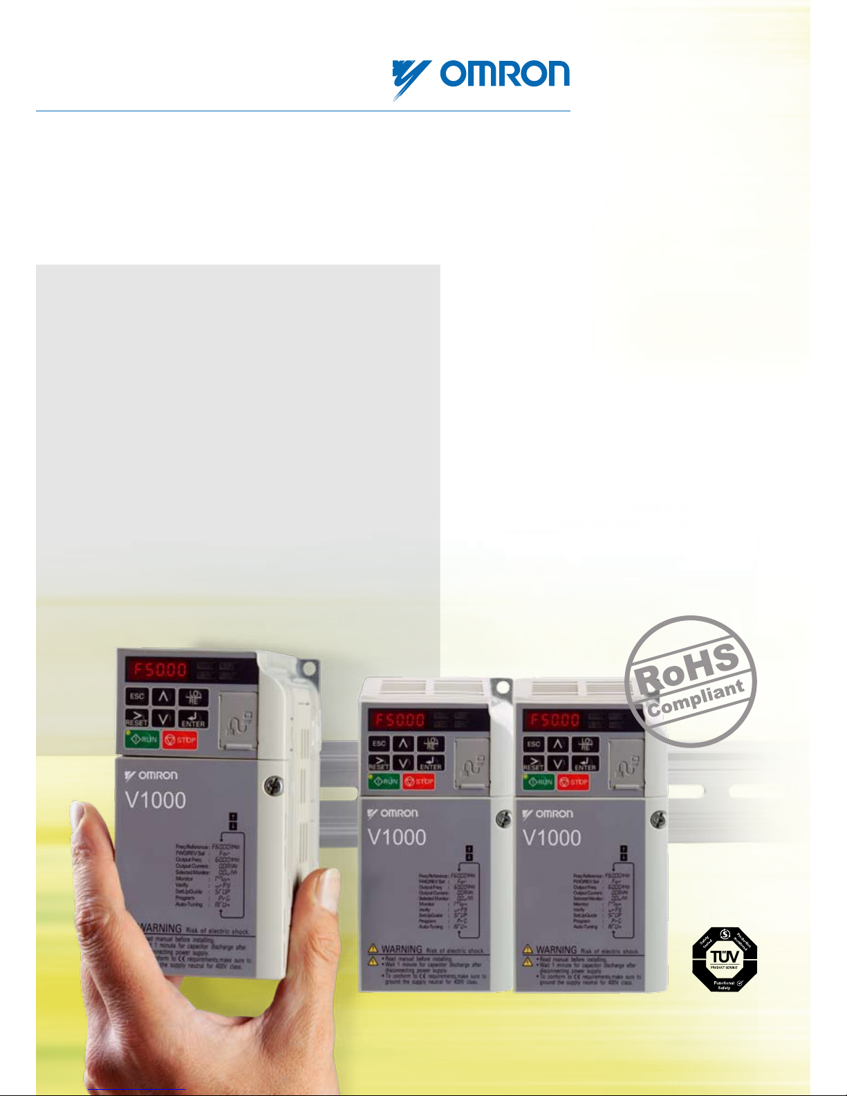
set up, it is also compacter by far. But the big difference
is that it takes quality and reliability to a new high level.
For no matter where you want it to operate, it will deliver
the same high performance for many years after you have
fitted it and forgotten about it.
Our obsession with quality
Our obsession with quality has resulted in the most
dependable products available in the industry today.
And we never stop working to improve quality even
further. This is fully reflected in our latest inverter, the
V1000, which incorporates decades of experience
in developing high quality industrial products.
The V1000 Inverter is the result of years
of experience as the European market leader and
represents a revolution in inverter design.
Compact and sensor-less, the V1000 has all of the
features and performance that you have grown
to expect from the world’s leading inverter/drive
manufacturer. But you have not met an inverter
quite like the V1000.
Quality has a new formula
Page 3

Advanced Industrial Automation
10,00
8,00
6,00
4,00
2,00
20%
Temperature ºC
113.000
105.125
97.2500
89.3750
81.5000
73.6250
65.7500
57.8750
50.0000
OK
Features of the V1000 Inverter
• Up to 15 kW
• World’s smallest compact inverter
• Built-in filter
• 10-years service life
• Control terminal board with memory (Patent pending)
• Faster CPU’s
• Current vector control
• Low-noise technology (Patent pending)
• IM & PM Motor control
• On-line tuning (Patent pending)
• Safety embedded
Mechanical advances
The V1000 design has not only reduced
volume by up to 40% compared with
previous inverters, tests prove that
it has increased vibration resistance
from 20Hz to 50Hz (0.6G) and heat
dissipation has also been greatly
increased, thanks to a new, hybrid
heat-sink system (patent pending).
Proven reliability
To improve quality even further,
a complete revision of production lines
has taken place and human error has
been reduced by installing the most
advanced robotic technology available.
The result is an expected failure rate
of less than 0.01%.
Performance guaranteed
V1000 is able to increase the output
current by around 20% when moving
down in frequency carrier thanks to its
double rating. The standard setting
is heavy duty (HD: 150% rated current/
1min) and increasing output current
when in the normal duty mode
(ND: 120% rated current/1 Min).
1 5 10 15
years
1%
3%
5%
Market standard
Omron-Yaskawa V1000
New Heatsink temperature evaluation Conventional inverter vs V1000
Market standard
Omron-Yaskawa V1000
C.Frq. (KHz)
Noisy operation Silent operation
2,5 3 5 6 7,5 10 12 14
0
2
4
6
8
10
12
11,1
V1000 double rating
Amps
Failure rate for drives
Page 4

Time and space saving 100% guaranteed
Space-saving side-by-side mounting
Remember when side-by-side
mounting meant having to leave
spaces for ventilation? Well, not with
the V1000. A special alloy, hybrid
cooling fin (patent pending) allows you
to mount multiple units close together
without overheating problems and
saving vast amounts of panel space.
Time-saving screw-less terminals
Have you ever stopped to think how
much time it takes to wire hundreds
of terminals with twelve screws per
inverter? With the V1000, you can
reduce installation time (and therefore
costs) considerably thanks to the use
of screw-less terminals.
Cost-saving EMC filter
A built-in EMC filter will save you the
task of having to take special
precautions for EMC shielding during
installation. The optional, factory-
installed filter will not only save on
installation costs, it also reduces the
bill of materials for external parts and
simplifies logistics.
Easy Shielding
Page 5
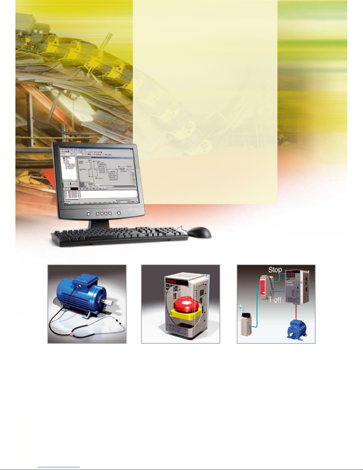
Work-saving set-up
Setting up Omron inverter and servo drives is now easier than
ever, following the release of a new version of the company’s
versatile CX-Drive drive configuration software package.
New features, all of which save time, include automatic recognition
of drive series and type, an oscilloscope function, and facilities
for connecting a single PC running Configurator to multiple drives.
During parameter selection, all parameters are fully described,
and many, including those associated with PID loops and jump
frequency operation, are set with the aid of graphical control
diagrams. Extensive help screens and tool tips are also provided.
In addition to aiding drive setup, Omron’s CX-Drive also provides
comprehensive facilities, status indications and alarms to assist
with commissioning and fault-finding. Drive inputs and outputs
can be monitored in real time, while the oscilloscope function
allows detailed analysis of drive operation, without the need for
additional test equipment CX-Drive enhances connectivity through
Omron’s PLC and motion controllers by supporting DeviceNet,
SCU, Mechatrolink and Profibus connectivity.
Time-saving safety feature
Safety is embedded in the V1000 from the inside out, making it easy for you to integrate
the inverter into your machine system and avoid difficult connections to safety controllers.
Dual safety inputs (acc. To EN954-1 Safety Category 3) will disconnect the motor faster
at the first sign of trouble, while reducing external wiring and contactors.
Convenient on-line tuning
Unlike previous inverters, the V1000
has a smart ‘on-line tuning’ feature
that takes ‘auto-tuning’ a stage further.
This continuous method of tuning
ensures that any temperature
deviation large enough to affect
electrical parameters governing the
motor speed will be adjusted before
any speed variance can occur.
Page 6

Advanced performance…
V/F: 5%
V/F + PG: 0,03%
Voltage Vector Control: 1%
Open Loop Current Vector Control: 0,2%
speed (r/min)
torque (%)
100
50
speed
time
V/F: 5%
V/F + PG: 0,03%
Voltage Vector Control: 1%
Open Loop Current Vector Control: 0,2%
Fast scan cycle
The V1000 employs a dual CPU concept with a CPU device that
is four times faster than those on board previous inverters.
This means a faster-than-ever scan cycle that boosts motor
control performance, especially in current vector control
applications where speed is of the essence.
Accurate speed control
Unlike previous inverters, the V1000 delivers optimum speed
control and high starting torque thanks to the current vector
control. As opposed to other techniques, such as voltage vector
control, current vector control uses the flux current, which is
an actual measurement rather than an estimated value.
Silent operation
A feature of the V1000 that will delight your customers is the
noise-suppression function that decreases motor noise at low
carrier frequencies. This puts machine operators at less risk
to safety hazards and has a positive effect on the general
working ambience.
Speed Fluctuation Rates
Speed Response Accuracy
Page 7
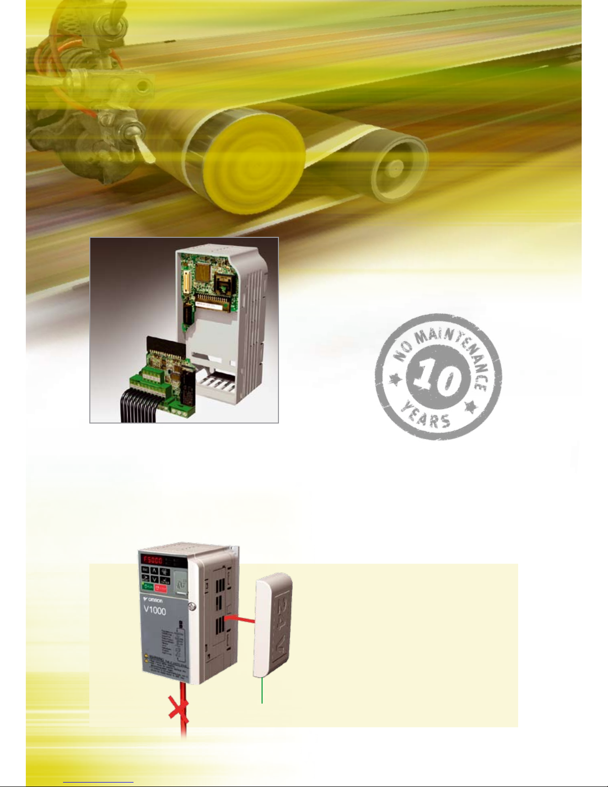
…Easy maintenance
Minimize downtime
The V1000 has an ingenious pre-maintenance function that will
calculate the condition of electronic components and advise
about their replacement based not only on the number of hours
they have been in service, but also on factors such as stress
due to load, temperature, the number of times they have been
powered up, output frequency and carrier frequency, etc.
Keeps running
Assuring that new data and communications keep flowing
in the event of a power failure is critical in many applications.
Naturally, the V1000 is available with a 24Vdc power supply
that will keep the CPU working in any power-down situation.
Save repetition
Control parameters need only be set once with the V1000.
They are automatically saved to a control terminal board
memory that allows you to replace an inverter and simply
forget it. The new inverter will be immediately updated with
the current settings.
24 Vdc
Main Power Supply
Page 8

1V1000
VZ
V1000
More performance & Quality in less space
• Current vector control
• High starting torque (200% / 0.5 Hz)
• 1:100 speed control range
• Double rating ND 120%/1min and HD 150%/1 min
• IM&PM motor control
• Online Tuning
• Low-noise Low carrier technology
• 10 years lifetime design
• Built-in filter
• Screw-less terminals
• Control Terminals with memory backup
• 24 VDC control board power supply option
• Fieldbus communications: Modbus, Profibus, CanOpen,
DeviceNet, Lonworks, CompoNet, Ethernet
• Safety embedded (EN954-1 safety cat. 3)
• CE, UL, cUL and TUV
Ratings
• 200 V Class single-phase 0.1 to 4 kW
• 200 V Class three-phase 0.1 to 15 kW
• 400 V Class three-phase 0.2 to 15 kW
System configuration
RJ-45 / USB
Adapter
Remote Operator
Extansion Cable
USB Cable
24Vdc Control Board Power Supply
Communication Option Board
Braking Resistor
DC Reactor
Mounting Accesories
LCD Remote
Operator
MCCB
V1000
Filter
AC Reactor
Motor
Ground
Power
Supply
CX-Drive
CX-One
V10008
Page 9

2 Frequency inverters
Type designation
200 V class
400 V class
Specifications
Single-phase: VZ-@ B0P1 B0P2 B0P4 B0P7 B1P5 B2P2 B4P0 - - - -
Three-phase: VZ-@ 20P1 20P2 20P4 20P7 21P5 22P2 24P0 25P5 27P5 2011 2015
Motor
kW
1
1. Based on a standard 4-pole motor for maximum applicable motor output:
Heavy Duty (HD) mode with a 150% overload capacity
Normal Duty (ND) mode with a 120% overlaod capacity
For HD setting 0.12 0.25 0.4 0.75 1.5 2.2 4.0 5.5 7.5 11 15
For ND setting 0.18 0.37 0.75 1.1 2.2 3.0 5.5 7.5 11 15 18.5
Output
characteristics
Inverter capacity kVA
0.3 0.6 1.1 1.9 3.0 4.2 6.7 9.5 13 18 23
Rated output current (A) at HD
0.8 1.6 3.0 5.0 8.0 11.0 17.5 25.0 33.0 47.0 60.0
Rated output current (A) at ND
1.2 1.9 3.5 6.0 9.6 12.0 21.0 30.0 40.0 56.0 69.0
Max. output voltage
Proportional to input voltage: 0..240 V
Max. output frequency
400 Hz
Power
supply
Rated input voltage
and frequency
Single-phase 200..240 V 50/60 Hz
3-phase 200..240 V 50/60 Hz
Allowable voltage
fluctuation
-15%..+10%
Allowable frequency
fluctuation
+5%
Three-phase: VZ-@
40P2 40P4 40P7 41P5 42P2 43P0 44P0 45P5 47P5 4011 4015
Motor
kW
1
1. Based on a standard 4-pole motor for maximum applicable motor output:
Heavy Duty (HD) mode with a 150% overload capacity
Normal Duty (ND) mode with a 120% overlaod capacity
For HD setting 0.2 0.4 0.75 1.5 2.2 3.0 4.0 5.5 7.5 11 15
For ND setting 0.37 0.75 1.5 2.2 3.0 3.7 5.5 7.5 11 15 18.5
Output
characteristics
Inverter capacity kVA
0.9 1.4 2.6 3.7 4.2 5.5 7.2 9.2 14.8 18 24
Rated output current (A) at HD
1.2 1.8 3.4 4.8 5.5 7.2 9.2 14.8 18.0 24 31
Rated output current (A) at ND
1.2 2.1 4.1 5.4 6.9 8.8 11.1 17.5 23 31 38
Max. output voltage
0..480V (proportional to input voltage)
Max. output frequency
400 Hz
Power
supply
Rated input voltage
and frequency
3-phase 380..480 VAC, 50/60 Hz
Allowable voltage
fluctuation
-15%..+10%
Allowable frequency
fluctuation
+5%
V1000 series
A: Standard specs
V Z A B 0 P 1 B A A
Version
Enclosure, Fin, Filter:
C: IP20 with top cover
B: IP20 without top cover
F: Nema 1
H: IP20 with top cover and C3 filter
Voltage:
B: Single-phase 200 VAC
2: Three-phase 200 VAC
4: Three-phase 400 VAC
Z: European standard
specifications
Coating specs:
A: Standard
[”P” indicates a decimal point]
Max. applicable motor output
0P1: 0.1 kW
~
015: 15 kW
Frequency inverters 9
Page 10

V1000 3
Commom specifications
Specifications
Model number
VZ-@
Specifications
Control functions
Control methods
Sine wave PWM (V/f control, sensorless current vector control)
Output frequency range
0.1..400 Hz
Frequency tolerance
Digital set value: ±0.01% (-10..+50 ºC)
Analogue set value: ±0.1% (25 ±10 ºC)
Resolution of frequency set value
Digital set value: 0.01 Hz (<100 Hz), 0.1 Hz (>100 Hz)
Analogue set value: 1/1000 of maximum frequency
Resolution of output frequency
0.01 Hz
Overload capability
Heavy duty use: 150% rated output current for one minute
Normal duty use: 120% rated output current for one minute
Frequency set value
0..10 V (20 kΩ), 4..20 mA (250 Ω), 0..20 mA (250 Ω)
Pulse train input, frequency setting value (selectable)
Braking torque
(short term peak torque)
Short-term average deceleration torque: 150% (up 1.5 kW), 100% (for 1.5 kW), 50% (for 2.2 kW), 20% (fof bigger size)
Continous regenerative torque: Aprox 20% (125% with optional braking resistor, 10%ED, 10 s, braking transistor built itn)
V/f Characteristics
Possible to program any V/f pattern
Functionality
Inputs signals
Seven of the following input signals are selectable: Forward/reverse run (3-wire sequence), fault reset, external fault (NO/NC
contact input), multi-step speed operation, Jog command, accel/decel time select, external baseblock, speed search com-
mand, UP/DOWN command, accel/decel hold command, LOCAL/REMOTE selection, communication/control circuit terminal
selection, mergency stop fault, emergency stop alarm, self test
Output signals
Following output signals are selectable (NO/NC contact output, 2 photo-coupler outputs): Fault, running, zero speed, speed
agree, frequency detection (output frequency <= or => set value), during overtorque detection, minor error, during baseblock,
operation mode, inverter run ready, during fault retry, during undervoltage detection, reverse running, during speed search,
data output through communication.
Standard functions
Open-loop vector control, full-range automatic torque boost, slip compensation, 17-step speed operation (max.), restart after
momentary power loss, DC injection braking current at stop/start (50% of inverter rated current, 0.5 sec, or less), frequency
reference bias/gain, MEMOBUS communications (RS-485/422, max. 115K bps), fault retry, speed search, frequency upper/
lower limit setting, overtorque detection, frequency jump, accel/decel time switch, accel/decel prohibited, S-curve accel/decel,
PID control, energy-saving control, constant copy.
Analogue inputs
2 analogue inputs, 0..10 V, 4..20 mA, 0..20 mA
Braking/acceleration times
0.01..6000 s
Display
Optionally frequency, current or set value
Error and status LED
Protection functions
Motor overload protection Electronic thermal overload relay
Instantaneous overcurrent Motor coasts to a stop at approx. 250% of inverter rated current
Overload
Heavy Duty: Motor coasts to a stop after 1 minute at 150% of inverter rated output current
Normal Duty: Motor coasts to a stop after 1 minute at 120% of inverter rated output current
Overvoltage Motor coasts to a stop if DC bus voltage exceed 410 V (double for 400 V class)
Undervoltage
Stops when DC bus voltage is approx. 190 V or less (double for 400 V class)
(approx. 150 V or less for single-phase series)
Momentary power loss
Following items are selectable: not provided (stop if power loss is 15 ms or longer), continuous operation if power loss is
approx. 0.5 s or shorter, continuous operation
Cooling fin overheat Protected by thermister
Stall prevention level Stall prevention during acceleration/deceleration and constant speed operation
Ground fault Protected by electronic circuit (operation level is approx. 250% of rated output current)
Power charge indication Indicates until the main circuit voltage reaches 50 V.
Ambient conditions
Degree of protection
IP20, NEMA1
Cooling
Cooling fan is provided for 200 V, 0.75 kW (1HP) (3/single-phase)
400 V, 1.5 kW (2HP) (3-phase), others are self-cooling
Ambient humidity
95% RH or less (without condensation)
Storage temperature
-20 ºC..+60 ºC (short-term temperature during transportation)
Installation
Indoor (no corrosive gas, dust, etc.)
Installation height
Max. 1000 m
Vibration
Up to 1 G at 10 to less than 20 Hz, Up to 0.65 G at 20 to 50 Hz
V100010
Page 11

4 Frequency inverters
IP 20 type 0.1 to 4 kW
V1000 + Option board
Dimensions
Voltage class
Max. applicable
motor output kW
Inverter model VZA Figure
Dimensions in mm
W1 H1 W H D t1 H2 D1 H3 H4 Weight
Single-phase
200 V
0.12 B0P1
1 56
118
68
128
76 3
5
6.5
- -
0.6
0.25 B0P2 0.7
0.55 B0P4 108
5
38.5 1.0
1.1 B0P7
2
96 108
137.5
58
1.5
1.5 B1P5 154 1.5
2.2 B2P2 128 140 163 65 2.1
4.0 B4P0 Under development
Three-phase
200 V
0.12 20P1
1 56
118
68
128
76 3
5
6.5
- -
0.6
0.25 20P2 0.6
0.55 20P4 108
5
38.5
0.9
1.1 20P7 128 1.1
1.5 21P5
2
96 108
129
58
1.3
2.2 22P2 137.5 1.4
4.0 24P0 128 140 143 65 2.1
5.5 25P5
3
122 248 140 254 140
-
6 55 13
6.2
3.8
7.5 27P5 3.8
11 2011 160 284 180 290 163 8 75
15
5.5
15 2015 192 336 220 358 187 7 78 7.2 9.2
Three-phase
400 V
0.37 40P2
2
96
118
108
128
81
5 5
10
- -
0.8
0.55 40P4 99 28 1.0
1.1 40P7 137.5
58
1.4
1.5 41P5
154
1.5
2.2 42P2 1.5
3.0 43P0 1.5
4.0 44P0 128 140 143 65 2.1
5.5 45P5
3
122 248 140 254 140
-
6
55
13
6 3.8
7.5 47P5 6.2 3.8
11 4011
160 284 180 290
143
8 15 6
5.2
15 4015 163 75 5.5
t1
D
D1
4-M4
H
W1
W
H2 H1
Figure 1
Figure 2
D1
t1
D
2-M4
W1
H1H2
W
H
Frequency inverters 11
Page 12

V1000 5
Built-in Filter Dimensions
Schaffner footprint Filters
VZA-
Dimensions in mm
W H H1 D1 D2 D
B0P1
68
178 50
69.5 6.5 76
B0P2
B0P4 79.5 38.5 118
B0P7
108
77.9 59.6 137.5
B1P5 89.4 64.6 154
B2P2
140 183 55 96.4 66.6 163
B4P0
Under development
40P2
108 178 50
69.4 11.6 81
40P4 29.6 99
40P7
77.9
59.6
137.5
41P5
94.4 154
42P2
43P0
44P0
140 183 55 76.4 66.6 143
45P5
Under development
47P5
4011
4015
Schaffner model
Dimensions
A B C D E F G H I J K L
3x200 V
A1000-FIV2010-SE 194 82 50 160 181 62 5.3 M5 25 56 118 M4
A1000-FIV2020-SE 169 111 50 135 156 91 5.5 M5 25 96 118 M4
A1000-FIV2030-SE 174 144 50 135 161 120 5.3 M5 25 128 118 M4
A1000-FIV2050-SE
Under development
A1000-FIV2100-SE
1x200 V A1000-FIV1010-SE 169 71 45 135 156 51 5.3 M5 22 56 118 M4
A1000-FIV1020-SE 169 111 50 135 156 91 5.3 M5 25 96 118 M4
A1000-FIV1030-SE 174 144 50 135 161 120 5.3 M5 25 128 118 M4
A1000-FIV1040-SE 174 144 50 135 161 150 5 M5 25 158 118 M4
3x400 V
A1000-FIV3005-SE 169 111 45 135 156 91 5.3 M5 22 96 118 M4
A1000-FIV3010-SE 169 111 45 135 156 91 5.3 M5 22 96 118 M4
A1000-FIV3020-SE 174 144 50 135 161 120 5 M5 25 128 118 M4
A1000-FIV3030-SE 304 184 56 264 288 150 6 M5 28 164 244 M5
A1000-FIV3050-SE Under development
V100012
Page 13

6 Frequency inverters
Rasmi footprint Filters
DIN rail mounting bracket
Rasmi model
Dimensions
Weight
W H L X Y M KG
3x200 V
A1000-FIV2010-RE 82 50 194 181 62 M4 0.8
A1000-FIV2020-RE 111 50 194 181 62 M4 1.1
A1000-FIV2030-RE 144 50 174 161 120 M4 1.3
A1000-FIV2060-RE 150 52 320 290 122 M5 2.4
A1000-FIV2100-RE 188 62 362 330 160 M5 4.2
1x200 V A1000-FIV1010-RE 71 45 169 156 51 M4 0.6
A1000-FIV1020-RE 111 50 169 156 91 M4 1.0
A1000-FIV1030-RE 144 50 174 161 120 M4 5.3
A1000-FIV1040-RE Under development
3x400 V
A1000-FIV3005-RE 111 45 169 156 91 M4 1.1
A1000-FIV3010-RE 111 45 169 156 91 M4 1.1
A1000-FIV3020-RE 144 50 174 161 120 M4 1.3
A1000-FIV3030-RE 150 52 306 290 122 M5 2.1
A1000-FIV3050-RE 182 62 357 330 160 M5 2.9
Inverter DIN rail mounting bracket
3-phase 200 VAC
VZ - 20P1/ 20P2 / 20P4/ 20P7 EZZ08122A
VZ - 21P5/ 22P2 EZZ08122B
VZ - 24P0 EZZ08122C
Single-phase 200 VAC
VZ - B0P1/ B0P2/ B0P4 EZZ08122A
VZ - B0P7/ B1P5 EZZ08122B
VZ - B2P2 EZZ08122C
VZ - B4P0 EZZ08122D
3-phase 400 VAC
VZ - 40P2/ 40P4/ 40P7/ 41P5/ 42P2 EZZ08122B
VZ - 44P0 EZZ08122C
EZZ08122A EZZ08122B
Four, M4 tap
Four, M4 tap
Four, M4 tap
Four, M4 tap
EZZ08122C
EZZ08122D
Side view
(common to
all the units)
35.1
DIN rail
Frequency inverters 13
Page 14

V1000 7
Heatsink attachment and Panel cut dimensions
Fig 1
Heatsink External Mounting Attachment
Panel Cit for External Mounting of Cooling Fin (Heatsink)
Mounting Panel
D3 for more
2 - 5 Dia. Holes
4-d Tap
VZA Reference
Frame
Panel Cutting
W
H W1 H1 D1 D2 D3 Fig (W2) (W3) (H2) (H3) A B
3x200v
20P1
100-034-075
68
128
56
118
69.2
12 30
2 -
20P2
20P4 100-034-076 42 50
20P7 100-034-077 62 70
21P5
100-034-079
108 96
71
58 70 3 -
22P2 79.5
24P0 100-034-080
140 128 86.5 53.5 60 4 -
25P5
100-036-300
158 286 122 272 86.6 53.4 60
1
9
9
8.5
7
140 255
27P5
2011 100-036-301
198 322 160 308 89.6 73.4 80 10 10.5 180 287
2015 100-036-302
241 380 192 362 110.6 76.4 85 14 10.5 10.5 9 220 341
1X200v
B0P1
100-034-075
68
128
56
118
69.2 12 30
2 -B0P2
B0P4 100-034-076 79.2 42 50
B0P7 100-035-418
108 96
79.5
58
70
3 -
B1P5 100-034-079 96
B2P2 100-034-080
140 128 98 65 4 -
B4P0 100-036-357
Under development
3X400v
40P2 100-034-078
108
128
96
118
71 13.2 30
3 -
40P4
100-036-418
28 40
40P7 79.5
58
70
41P5
100-034-079 9642P2
43P0
44P0 100-034-080
140 128 78 65 4 -
45P5
100-036-300
158 286 122 272
86.6
53.4 60
1
9
9
8.5
7
140 255
47P5
198 322 160 308 10 10.5 180 2874011
100-036-301
4015 73.4 80
Fig 3
Fig 2
Fig 4
V100014
Page 15

8 Frequency inverters
Standard connections
Power
Supply
R/L1
S/L2
T/L3
S1
S2
S3
S4
S5
S6
㪄
B1+1+2 B2
L1
L2
L3
U/T1
V/T2
W/T3
24 V
0 V
SINK
SOURCE
MA
P1
MB
MC
+24 V 8 mA
M
U
V
W
SC
P2
MP
AM
AC
PC
IG
R+
R−
S+
S−
H2
RP
+V
A1
A2
AC
2 k
Ω
HC
H1
DC reactor
(option)
For 1-phase
power supply use
R/L1 and S/L2
Filter
Fuses
Main
Switch
Forward/Stop
Reverse/Stop
External Fault
Fault Reset
Multi-speed 1
Multi-speed 2
Multi-function
digital inputs
(default setting)
Link
Thermal
relay
Braking
resistor
(opt)
V1000
Ground
Multi-function relay output
250 Vac / 30 VDC (10 mA to 1A)
(default setting)
Fault
During run
Frequency agree
Photocoupler
common
Multi-function photocoupler output
48 VDC, max. 50 mA
(default setting)
DIP
switch S3
Shielded ground
terminal
Pulse Input
(max. 32kHz)
Multi-function analog input 1
0 to 10 V (20 k
Ω)
Multi-function analog input 2
0 to 10 V (20 k
Ω) or
0/4 to 20 mA (250
Ω)
Analog input power supply
+10.5 VDC, max. 20 mA
Multi- function pulse / analog inputs
(default: frequency reference)
Safe Disable
inputs
Monitor outputs
(default setting)
Analog output
0 to +10 VDC (2mA)
(Output frequency)
Pulse train output
(max. 32 kHz)
(Output frequency)
Terminal resistance
(120
Ω, 1/2 W)
Memobus comm.
RS-485/422
max. 115 kBps
Shielded
Cable
Symbols:
Use twisted pair cables
Use shielded twisted pair cables
Indicates a main circuit terminal
Indicates a control circuit terminal.
Frequency inverters 15
Page 16

V1000 9
Main circuit
Control Circuit
Terminal Name Function (signal level)
R/L1, S/L2, T/L3
Main circuit power supply input Used to connect line power to the drive.
Drives with single-phase 200 V input power use only terminals R/L1 and S/L2
(T/L3 is not connected to anything)
U/T1, V/T2, W/T3
Inverter output Used to connect the motor
B1, B2
Braking resistor connection Available for connecting a braking resistor or the braking resistor unit option.
+2, +1
DC reactor connection Remove the short bar between +2 and +1 when connecting DC reactor (option)
+1, –
DC power supply input For power supply input (+1: positive electrode; – : negative electrode)*
Grounding For grounding (grounding should conform to the local grounding code.)
Type No.
Signal name Function Signal level
Digital input signals
S1
Multi-function input selection 1 Factory setting: runs when CLOSED, stops when OPEN.
24 VDC, 8 mA
photocoupler
insulation
S2
Multi-function input selection 2 Factory setting: runs when CLOSED, stops when OPEN.
S3
Multi-function input selection 3 Factory setting: External Fault (N.O.)
S4
Multi-function input selection 4 Factory setting: Fault reset
S5
Multi-function input selection 5 Factory setting: Multi-step speed cmd 1
S6
Multi-function input selection 6 Factory setting: Multi-step speed cmd 2
SC
Multi-function input selection
Common
Common for control signal
Analog input signals
RP
Main Speed Cmd Pulse Train Input 32 kHz max.
FS
Power Supply for Frequency Setting +10 V (allowable max current 20 mA)
FR1
Main Speed Freq Ref
Voltage input or current input
0 to +10 VDC (20 kΩ) (resolution 1/1000)
4 to 20 mA (250 Ω) or 0 to 20 mA (250 Ω) Resolution: 1/500
FR2
FC
Frequency reference common 0 V
Fast
Stop
Cmd
HC
Power Supply Fast Stop Cmd
+24 V (max allowable current 10 mA)
H1
Special Digital input
Open: Fast Stop Closed: Normal Operation
H2
Special Digital input
Digital output signals
MA
NO contact output
Factory setting: "fault"
Contact capacity
250 VAC,
1 A or less
30 VDC, 1 A
or less
MB
NC Output
MC
Relay Output common
P1
Photocoupler output 1 Factory setting: During run
Photocoupler output:
+48 VDC, 50 mA or
less
P2
Photocoupler output 2 Factory setting: Frequency Agree
PC
Photocoupler output common 0 V
Analog
output
signals
PM
Pulse train Output max 33 kHz
AM
Analog monitor output Factory setting: "output frequency" 0 to +10 V output Resolution: 1/1000
0 to 10 V 2 mA
or less
Resolution: 8 bits
AC
Analog monitor common 0 V
RS-485/422
R+
Communication input (+)
For MEMOBUS communication
operation by RS-485 or RS-422 communication is available.
RS-485/422
MEMOBUS
protocol
R–
Communication input (–)
S+
Communication output (+)
S–
Communication output (–)
V100016
Page 17

10 Frequency inverters
Inverter heat loss
Three-phase 200 V class
Single-phase 200 V class
Three-phase 400 V class
Model VZ 20P1 20P2 20P4 20P7 21P5 22P2 24P0 25P5 27P5 2011 2015
Inverter capacity kVA 0.3 0.6 1.1 1.9 3.0 4.2 6.7 9.5 13 18 23
Rated current (A) at HD 0.8 1.6 3 5 8 11 17.5 25 33 47.0 60.0
Rated current (A) at ND
1.2 1.9 3.5 6.0 9.6 12.0 21.0 30.0 40.0 56.0 69.0
Heat
loss W
HD
Fin 4.3 7.9 16.1 27.4 54.8 70.7 110.5 231.5 239.5 347.6 437.7
Inside unit 7.3 8.8 11.5 15.9 23.8 30.0 43.3 72.2 81.8 117.6 151.4
Total heat loss 11.6 16.7 27.7 43.3 78.6 100.6 153.8 303.7 321.3 465.2 589.1
Heat
loss W
ND
Fin 4.7 7.2 14.0 35.6 48.6 57.9 93.3 236.8 258.8 342.8 448.5
Inside unit 7.9 9.4 13.4 16.9 25.0 29.6 45.0 87.2 11.4 149.1 182.2
Total heat loss 12.6 16.6 28.5 43.1 73.6 87.5 138.2 324.0 370.3 491.9 630.7
Cooling Method Self Cooled Fan Cooled
Model VZ B0P1 B0P2 B0P4 B0P7 B1P5 B2P2 B4P0
Inverter capacity kVA 0.3 0.6 1.1 1.9 3.0 4.2 6.7
Rated current (A) at HD 0.8 1.6 3 5 8 11 17.5
Rated current (A) at ND
1.2 1.9 3.5 6.0 9.6 12.0 21.0
Heat
loss W
HD
Fin 4.3 7.9 16.1 42.5 54.8 70.7 110.5
Inside unit 7.4 8.9 11.5 19.0 25.9 34.1 51.4
Total heat loss 11.7 16.7 27.7 61.5 80.7 104.8 161.9
Heat
loss W
ND
Fin 4.7 7.2 15.1 26.2 48.6 57.9 93.3
Inside unit 8.4 9.6 14.3 20.8 29.0 36.3 58.5
Total heat loss 13.1 16.8 28.3 56.5 77.6 94.2 151.8
Cooling Method Self Cooled Fan Cooled
Model VZ 40P2 40P4 40P7 41P5 42P2 43P0 44P0 45P5 47P5 4011 4015
Inverter capacity kVA
0.9 1.4 2.6 3.7 4.2 5.5 7.2 9.2 14.8 18 24
Rated current (A) at HD
1.2 1.8 3.4 4.8 5.5 7.2 9.2 14.8 18.0 24 31
Rated current (A) at ND
1.2 2.1 4.1 5.4 6.9 8.8 11.1 17.5 23 31 38
Heat
loss W
HD
Fin 19.2 28.9 42.3 70.7 81.0 84.6 107.2 166.0 207.1 266.9 319.1
Inside unit 11.4 14.9 17.9 26.2 30.7 32.9 41.5 62.7 78.1 105.9 126.6
Total heat loss 30.6 43.7 60.2 96.9 111.7 117.5 148.7 228.7 285.2 372.7 445.8
Heat
loss W
ND
Fin 8.2 15.5 26.4 37.5 49.7 55.7 71.9 170.3 199.5 268.6 298.7
Inside unit 9.2 13.1 15.8 20.0 26.3 29.4 43.6 78.1 105.3 142.8 152.2
Total heat loss 17.4 28.6 42.2 57.5 76.0 85.1 115.5 248.4 304.8 411.4 450.9
Cooling Method Self Cooled Fan Cooled
a: Space required differs by model:
Up to 3.7 kW: minimum 30 mm
5.5 kW and above: minimum 50 mm
Side by Side mounting
a a
Airflow
At least
100 m
m
At least
100 mm
Frequency inverters 17
Page 18

V1000 11
Connections for braking resistor
AC reactor
DC reactor
200 V class 400 V class
Max. applicable
motor output kW
Current value
A
Inductance
mH
Max. applicable
motor output kW
Current value
A
Inductance
mH
0.12 2.0 2.0 ------
0.25 2.0 2.0 0.2
1.3 18.0
0.55 2.5 4.2 0.4
1.1 5 2.1 0.75 2.5 8.4
1.5 10 1.1 1.5 5 4.2
2.2 15 0.71 2.2 7.5 3.6
4.0 20 0.53 4.0 10 2.2
5.5 30 0.35 5.5 15 1.42
7.5 40 0.265 7.5 20 1.06
11 60 0.18 11 30 0.7
15 80 0.13 15 40 0.53
200 V class 400 V class
Max. applicable
motor output kW
Current value
A
Inductance
mH
Max. applicable
motor output kW
Current value
A
Inductance
mH
0.12
5.4 8
--------
0.25 0.2
3.2 280.55 0.4
1.1 0.75
1.5
18 3
1.5
5.7 11
2.2 2.2
4.0 4.0 12 6.3
5.5
36 1
5.5
23 3.6
7.5 7.5
11
72 0.5
11
33 1.9
15 15
Power
supply
Thermal
relay
Motor
VZ
Braking resistor
Thermal relay switch for
external braking resistor
Fault contact
MC
SA
SA
SA
MCON
MC
OFFTHRX
THRX
TRX
MC
TRX
FLT-A FLT-B
R/L1
B1 B2
S/L2
T/L3
U/T1
V/T2
W/T3
MCCB
MCCB
Power supply
AC reactor
VZ
R/L1U
V
W
X
YZS/L2
T/L3
Power
supply
VZ
DC reactor
R/L1
+1 +2
MCCB
S/L2
T/L3
V100018
Page 19

12 Frequency inverters
Safety System
R/L1
S/L2
T/L3
S1
S2
S3
S4
S5
S6
−
B1+ 1+2 B2
U/T1
V/T2
W/T3
24 V
0 V
SINK
SOURCE
MAP1MB
MC
+24 V 8 mA
SC
P2
MP
AM
AC
PC
IG
R+R−S+S
−
H2
RP
+V
A1
A2
AC
HC
H1
DC reactor
V1000
Ground
Analog output
0 to +10 VDC (2mA)
Pulse train
output
Terminal resistance
(120
Ω, 1/2 W)
RS-485/422
K1
K2
K1
K1
K2
K2 K1
a
a
+
-
K2
TH
SA
A1 A2
T11 T12 T31 T32
13 23
33 4 1
14 24
34 4 2
T21
T22
Control
Circuit
Start
Power
Supply
Braking
resistor
Multi-function
digital inputs
MF relay
output
MF photo-
coupler output
DIP
switch S3
Shielded ground
terminal
Pulse Input
(max. 32kHz)
Analog input PS
+10.5 VDC, max. 20 mA
MF Analog input 1
0 to 10 V (20 kΩ)
MF Analog input 2
0 to 10 V (20 kΩ) or
0/4 to 20 mA (250 Ω)
Safe Disable
inputs
V1000 safe stop application using OMRON G9SB safety relay unit
complies to safety category 3 according EN 954-1 / Stop category 0
according EN60204
Ensure V1000 and safety relay are mounted in the same cabinet to
exclude cross circuit between H1 and H2
Frequency inverters 19
Page 20

V1000 13
V1000
Ordering information
Specifications Model
Heavy Duty Normal Duty Standard Built-in filter
1x200 V
0.12 kW 0.8 A 0.18 kW 0.8 A VZAB0P1BAA VZAB0P1HAA
0.25 kW 1.6 A 0.37 kW 1.6 A VZAB0P2BAA VZAB0P2HAA
0.55 kW 3.0 A 0.75 kW 3.5 A VZAB0P4BAA VZAB0P4HAA
1.1 kW 5.0 A 1.1 kW 6.0 A VZAB0P7BAA VZAB0P7HAA
1.5 kW 8.0 A 2.2 kW 9.6 A VZAB1P5BAA VZAB1P5HAA
2.2 kW 11.0 A 3.0 kW 12.0 A VZAB2P2BAA VZAB2P2HAA
4.0 kW 17.5 A 5.5 kW 21.0 A VZAB4P0BAA VZAB4P0HAA
3x200 V
0.12 kW 0.8 A 0.18 kW 0.8 A VZA20P1BAA VZA20P1HAA
0.25 kW 1.6 A 0.37 kW 1.6 A VZA20P2BAA VZA20P2HAA
0.55 kW 3.0 A 0.75 kW 3.5 A VZA20P4BAA VZA20P4HAA
1.1 kW 5.0 A 1.1 kW 6.0 A VZA20P7BAA VZA20P7HAA
1.5 kW 8.0 A 2.2 kW 9.6 A VZA21P5BAA VZA21P5HAA
2.2 kW 11.0 A 3.0 kW 12.0 A VZA22P2BAA VZA22P2HAA
4.0 kW 17.5 A 5.5 kW 21.0 A VZA24P0BAA VZA24P0HAA
5.5 kW 25.0 A 7.5 kW 30.0 A VZA25P5FAA VZA25P5HAA
7.5 kW 33.0 A 11.0 kW 40.0 A VZA27P5FAA VZA27P5HAA
11 kW 47.0 A 15.0 kW 56.0 A VZA2011FAA VZA2011HAA
15 kW 60.0 A 18.5 kW 69.0 A VZA2015FAA VZA2015HAA
3x400 V
0.2 kW 1.2 A 0.37 kW 1.2 A VZA40P2BAA VZA40P2HAA
0.4 kW 1.8 A 0.75 kW 2.1 A VZA40P4BAA VZA40P4HAA
0.75 kW 3.4 A 1.5 kW 4.1 A VZA40P7BAA VZA40P7HAA
1.5 kW 4.8 A 2.2 kW 5.4 A VZA41P5BAA VZA41P5HAA
2.2 kW 5.5 A 3.0 kW 6.9 A VZA42P2BAA VZA42P2HAA
3.0 kW 7.2 A 3.7 kW 8.8 A VZA43P0BAA VZA43P0HAA
4.0 kW 9.2 A 5.5 kW 11.1 A VZA44P0BAA VZA44P0HAA
5.5 kW 14.8 A 7.5 kW 17.5 A VZA45P5FAA VZA45P5HAA
7.5 kW 18.0 A 11.0 kW 23.0 A VZA47P5FAA VZA47P5HAA
11 kW 24.0 A 15.0 kW 31.0 A VZA4011FAA VZA4011HAA
15 kW 31.0 A 18.5 kW 38.0 A VZA4015FAA VZA4015HAA
C
C
C
C
D
E
F
A
B
C
LCD Remote
Operator
MCCB
V1000
Filter
AC Reactor
Motor
Ground
Power
Supply
CX-Drive
CX-One
RJ-45 / USB
Adapter
Remote Operator
Extansion Cable
USB Cable
24Vdc Control Board Power Supply
Communication Option Board
Braking Resistor
DC Reactor
Mounting Accesories
V100020
Page 21

14 Frequency inverters
A Line filters
B Communication cards
C Accessories
D Computer software
Inverter Line filter Schaffner
Line filter Rasmi
Voltage Model VZ Reference Rated current (A) Weight (kg) Reference Rated current (A) Weight (kg)
3-Phase 200 VAC
20P1 / 20P2 / 20P4 / 20P7 A1000-FIV2010-SE 10 0.7 A1000-FIV2010-RE 10 0.8
21P5 / 22P2 A1000-FIV2020-SE 20 0.9 A1000-FIV2020-RE 20 1.1
24P0 A1000-FIV2030-SE 30 1.0 A1000-FIV2030-RE 30 1.3
25P5 / 27P5 A1000-FIV2050-SE
Under development
A1000-FIV2060-RE 58 2.4
2011 / 2015 A1000-FIV2100-SE A1000-FIV2100-RE 96 4.2
Single-Phase 200
VAC
B0P1 / B0P2 / B0P4 A1000-FIV1010-SE 10 0.5 A1000-FIV1010-RE 10 0.6
B0P7 / B1P5 A1000-FIV1020-SE 20 0.7 A1000-FIV1020-RE 20 1.0
B2P2 A1000-FIV1030-SE 30 1.0 A1000-FIV1030-RE 30 1.1
B4P0 A1000-FIV1040-SE 40 1.1 A1000-FIV1040-RE 40 -
3-Phase 400 VAC
40P2 / 40P4 A1000-FIV3005-SE 5 0.5 A1000-FIV3005-RE 5 1.1
40P7 / 41P5 / 42P2 / 43P0 A1000-FIV3010-SE 10 0.75 A1000-FIV3010-RE 10 1.1
44P0 A1000-FIV3020-SE 15 1.0 A1000-FIV3020-RE 20 1.3
45P5 / 47P5 A1000-FIV3030-SE
Under development
A1000-FIV3030-RE 29 2.1
4011 / 4015 A1000-FIV3050-SE A1000-FIV3050-RE 48 2.9
Type Model Description Function
Communication
option board
SI-N3/V DeviceNet option card
• Used for running or stopping the inverter, setting or referencing parameters, and monitoring
output frequency, output current, or similar items through DeviceNet communication with the
host controller.
SI-P3/V PROFIBUS-DP option card
• Used for running or stopping the inverter, setting or referencing parameters, and monitoring
output frequency, output current, or similar items through PROFIBUS-DP communication
with the host controller.
SI-S3/V Can open option card
• Used for running or stopping the inverter, setting or referencing parameters, and monitoring
output frequency, output current, or similar items through CANopen communication with the
host controller.
A1000 - CRT1 CompoNet option card • Under Development
Types Model Description Functions
Digital
operator
JVOP-180 LCD remote operator LCD Display operator with language support
72606-WV001 Remote operator cable (1 m)
Cable for connecting remote operator
72606-WV003 Remote operator cable (3 m)
Accessories
JVOP-181 USB converter / USB cable USB converter unit with copy and backup function
PS-UDC24 24 VDC option board 24V DC control board power supply
Types Model Description Installation
Software
CX-drive Computer software Configuration and monitoring software tool
CX-One Computer software Configuration and monitoring software tool
Frequency inverters 21
Page 22

V1000 15
E Braking unit, braking resistor unit
F Mounting accesories
Inverter Braking resistor unit
Voltage
Max.
applicable
motor
output kW
Inverter model VZ
Connectable min.
resistance Ω
Inverter-mounted type (3 %ED, 10 sec max)
Three-phase Single-phase ERF-150WJ_ Resistance Ω No. of used Braking torque %
200 V
(single-/
three-phase)
0.12 20P1 B0P1 300 401 400 1 220
0.25 20P2 B0P2 300 401 400 1 220
0.55 20P4 B0P4 200 201 200 1 220
1.1 20P7 B0P7 120 201 200 1 125
1.5 21P5 B1P5 60 101 100 1 125
2.2 22P2 B2P2 60 700 70 1 120
4.0 24P0 B4P0 32 620 62 1 100
5.5 25P5 – 16
–-- ---
7.5 27P5 – 9.6
11 2011 9.6
15 2015 9.6
400 V
(threephase)
0.37 40P2 – 750 751 750 1 230
0.55 40P4 – 750 751 750 1 230
1.1 40P7 – 510 751 750 1 130
1.5 41P5 – 240 401 400 1 125
2.2 42P2 – 200 301 300 1 115
3.0 43P0 –
100 401 400 2 105
4.0 44P0 –
5.5 45P5 – 32
–-- –--
7.5 47P5 – 32
11 4011 - 20
15 4015 - 20
Types Model Description Applicable models
DIN Rail
EZZ08122A
Necessary to mount the inverter on a DIN rail
VZ-20P1/20P2/20P4/20P7
VZ-B0P1/B0P2/B0P4
EZZ08122B
VZ-21P5/22P2
VZ-B0P7/B1P5
VZ-40P2/40P4/40P7/41P5/42P2
EZZ08122C
VZ-24P0
VZ-B2P2
VZ-44P0
EZZ08122D VZ-B4P0
Heatsink external mounting attachment
100-034-075
Additional items to mount the inverter with the heat-
shink out of the panel.
VZ-20P1/20P2
VZ-B0P1/B0P2
100-034-076
VZ-20P4
VZ-B0P4
100-034-077
VZ-20P7
100-034-078
VZ-40P2
100-034-079
VZ-21P5/22P2
VZ-B1P5
VZ-41P5/42P2/43P0
100-034-080
VZ-24P0
VZ-B2P2
VZ-44P0
100-036-357
VZ-B4P0
100-036-418
VZ-B0P7
VZ-40P2/40P4
100-036-300
VZ-25P5/27P5
VZ-45P5/47P5
100-036-301
VZ-2011
VZ-4011/4015
100-036-302
VZ-2015
V100022
Page 23

16 Frequency inverters
In the interest of product improvement, specifications are subject to change without notice.Cat. No. I68E-EN-01
OMRON EUROPE B.V.
Wegalaan 67-69,
NL-2132 JD, Hoofddorp,
The Netherlands
Phone: +31 23 568 13 00
Fax: +31 23 568 13 88
www.omron-industrial.com
Frequency inverters 23
Page 24

Austria
Tel: +43 (0) 2236 377 800
www.omron.at
Belgium
Tel: +32 (0) 2 466 24 80
www.omron.be
Czech Republic
Tel: +420 234 602 602
www.omron-industrial.cz
Denmark
Tel: +45 43 44 00 11
www.omron.dk
Finland
Tel: +358 (0) 207 464 200
www.omron.fi
France
Tel: +33 (0) 1 56 63 70 00
www.omron.fr
Germany
Tel: +49 (0) 2173 680 00
www.omron.de
Hungary
Tel: +36 1 399 30 50
www.omron.hu
Italy
Tel: +39 02 326 81
www.omron.it
Middle East & Africa
Tel: +31 (0) 23 568 11 00
www.omron-industrial.com
Netherlands
Tel: +31 (0) 23 568 11 00
www.omron.nl
Norway
Tel: +47 (0) 22 65 75 00
www.omron.no
Poland
Tel: +48 (0) 22 645 78 60
www.omron.pl
Portugal
Tel: +351 21 942 94 00
www.omron.pt
Russia
Tel: +7 495 648 94 50
www.omron-industrial.ru
Spain
Tel: +34 913 777 900
www.omron.es
Sweden
Tel: +46 (0) 8 632 35 00
www.omron.se
Switzerland
Tel: +41 (0) 41 748 13 13
www.omron.ch
Turkey
Tel: +90 (0) 216 474 00 40
www.omron.com.tr
United Kingdom
Tel: +44 (0) 870 752 08 61
www.omron.co.uk
Control Systems
• Programmable logic controllers • Human-machine interfaces • Remote I/O
Motion & Drives
• Motion controllers • Servo systems • Inverters
Control Components
• Temperature controllers • Power supplies • Timers • Counters • Programmable relays
• Digital panel indicators • Electromechanical relays • Monitoring products • Solid-state relays
• Limit switches • Pushbutton switches • Low voltage switch gear
Sensing & Safety
• Photoelectric sensors • Inductive sensors • Capacitive & pressure sensors • Cable connectors
• Displacement & width-measuring sensors • Vision systems • Safety networks • Safety sensors
• Safety units/relay units • Safety door/guard lock switches
Aut hori sed Di str ibu tor:
KPP_V1000_EN_INT02_0607
Although we strive for perfection, Omron Europe BV and/or its subsidiary and affiliated companies do not warrant
or make any representations regarding the correctness or completeness of the information described in this document.
We reserve the right to make any changes at any time without prior notice.
OMRON EUROPE B.V. Wegalaan 67-69, NL-2132 JD, Hoofddorp, The Netherlands. Tel: +31 (0) 23 568 13 00 Fax: +31 (0) 23 568 13 88 www.omron-industrial.com
More Omron representatives
www.omron-industrial.com
 Loading...