

Page 1
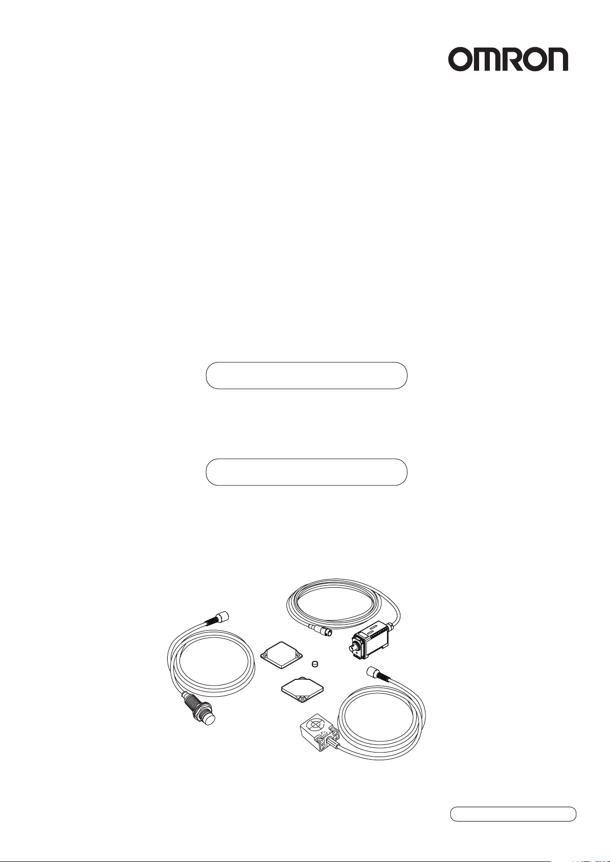
RFID System
V680 Series
User's Manual
Amplifier and Antennas
V680-HA63B
V680-HS52
V680-HS63
ID Tags
V680-D2KF52
V680-D2KF67
V680-D2KF67M
Cat. No.: Z248-E1-01
Page 2

Introduction
Thank you for purchasing a V680-series RFID System. This manual describes the functions, performance,
and application methods needed for optimum use of the V680-series RFID System.
Please observe the following items when using the RFID System.
• Allow the RFID System to be installed and operated only by qualified specialist with a sufficient
knowledge of electrical systems.
• Read and understand this manual before attempting to use the RFID System and use the RFID Sys-
tem correctly.
• Keep this manual in a safe and accessible location so that it is available for reference when required.
Page 3
Introduction
Introduction
Section 1
Section 2
Section 3
Section 4
Section 5
READ AND UNDERSTAND THIS DOCUMENT
Section 1 Section 2 Section 3 Section 4 Section 5
Product Overview
Specifications and Performance
Communications Specifications
Installation
Chemical Resistance
RFID System
V680-HA63B Amplifier
V680-HS52 Antenna
V680-HS63 Antenna
V680-D2KF52 ID Tag
V680-D2KF67 ID Tag
V680-D2KF67M ID Tag
User's Manual
Page 4

Introduction
Introduction
READ AND UNDERSTAND THIS DOCUMENT
Please read and understand this document before using the products. Please consult your OMRON representative if you have any questions or comments.
WARRANTY
OMRON’s exclusive warranty is that the products are free from defects in materials and workmanship for a period of one year (or other period if specified)
from date of sale by OMRON.
OMRON MAKES NO WARRANTY OR REPRESENTATION, EXPRESS OR IMPLIED, REGARDING NON-INFRINGEMENT, MERCHANTABILITY, OR FITNESS FOR PARTICULAR PURPOSE OF THE PRODUCTS. ANY BUYER OR USER ACKNOWLEDGES THAT THE BUYER OR USER ALONE HAS
DETERMINED THAT THE PRODUCTS WILL SUITABLY MEET THE REQUIREMENTS OF THEIR INTENDED USE. OMRON DISCLAIMS ALL OTHER
WARRANTIES, EXPRESS OR IMPLIED.
LIMITATIONS OF LIABILITY
OMRON SHALL NOT BE RESPONSIBLE FOR SPECIAL, INDIRECT, OR CONSEQUENTIAL DAMAGES, LOSS OF PROFITS OR COMMERCIAL LOSS IN
ANY WAY CONNECTED WITH THE PRODUCTS, WHETHER SUCH CLAIM IS BASED ON CONTRACT, WARRANTY, NEGLIGENCE, OR STRICT LIABILITY.
In no event shall responsibility of OMRON for any act exceed the individual price of the product on which liability is asserted.
IN NO EVENT SHALL OMRON BE RESPONSIBLE FOR WARRANTY, REPAIR, OR OTHER CLAIMS REGARDING THE PRODUCTS UNLESS OMRON’S
ANALYSIS CONFIRMS THAT THE PRODUCTS WERE PROPERLY HANDLED, STORED, INSTALLED, AND MAINTAINED AND NOT SUBJECT TO CONTAMINATION, ABUSE, MISUSE, OR INAPPROPRIATE MODIFICATION OR REPAIR.
SUITABILITY FOR USE
THE PRODUCTS CONTAINED IN THIS DOCUMENT ARE NOT SAFETY RATED. THEY ARE NOT DESIGNED OR RATED FOR ENSURING SAFETY OF
PERSONS, AND SHOULD NOT BE RELIED UPON AS A SAFETY COMPONENT OR PROTECTIVE DEVICE FOR SUCH PURPOSES. Please refer to
separate catalogs for OMRON's safety rated products.
OMRON shall not be responsible for conformity with any standards, codes, or regulations that apply to the combination of products in the customer’s application or use of the product.
At the customer’s request, OMRON will provide applicable third party certification documents identifying ratings and limitations of use that apply to the products. This information by itself is not sufficient for a complete determination of the suitability of the products in combination with the end product, machine,
system, or other application or use.
The following are some examples of applications for which particular attention must be given. This is not intended to be an exhaustive list of all possible uses
of the products, nor is it intended to imply that the uses listed may be suitable for the products:
• Outdoor use, uses involving potential chemical contamination or electrical interference, or conditions or uses not described in this document.
• Nuclear energy control systems, combustion systems, railroad systems, aviation systems, medical equipment, amusement machines, vehicles, safety
equipment, and installations subject to separate industry or government regulations.
• Systems, machines, and equipment that could present a risk to life or property.
Please know and observe all prohibitions of use applicable to the products.
NEVER USE THE PRODUCTS FOR AN APPLICATION INVOLVING SERIOUS RISK TO LIFE OR PROPERTY WITHOUT ENSURING THAT THE SYSTEM
AS A WHOLE HAS BEEN DESIGNED TO ADDRESS THE RISKS, AND THAT THE OMRON PRODUCT IS PROPERLY RATED AND INSTALLED FOR
THE INTENDED USE WITHIN THE OVERALL EQUIPMENT OR SYSTEM.
PERFORMANCE DATA
Performance data given in this document is provided as a guide for the user in determining suitability and does not constitute a warranty. It may represent the
result of OMRON’s test conditions, and the users must correlate it to actual application requirements. Actual performance is subject to the OMRON Warranty
and Limitations of Liability.
CHANGE IN SPECIFICATIONS
Product specifications and accessories may be changed at any time based on improvements and other reasons.
It is our practice to change model numbers when published ratings or features are changed, or when significant construction changes are made. However,
some specifications of the product may be changed without any notice. When in doubt, special model numbers may be assigned to fix or establish key specifications for your application on your request. Please consult with your OMRON representative at any time to confirm actual specifications of purchased
products.
DIMENSIONS AND WEIGHTS
Dimensions and weights are nominal and are not to be used for manufacturing purposes, even when tolerances are shown.
ERRORS AND OMISSIONS
The information in this document has been carefully checked and is believed to be accurate; however, no responsibility is assumed for clerical, typographical,
or proofreading errors, or omissions.
PROGRAMMABLE PRODUCTS
OMRON shall not be responsible for the user’s programming of a programmable product, or any consequence thereof.
COPYRIGHT AND COPY PERMISSION
This document shall not be copied for sales or promotions without permission. This document is protected by copyright and is intended solely for use in conjunction with the product. Please notify us before copying or reproducing this document in any manner, for any other purpose. If copying or transmitting this
document to another, please copy or transmit it in its entirety.
RFID System
2
User's Manual
Page 5
Introduction
Safety Precautions
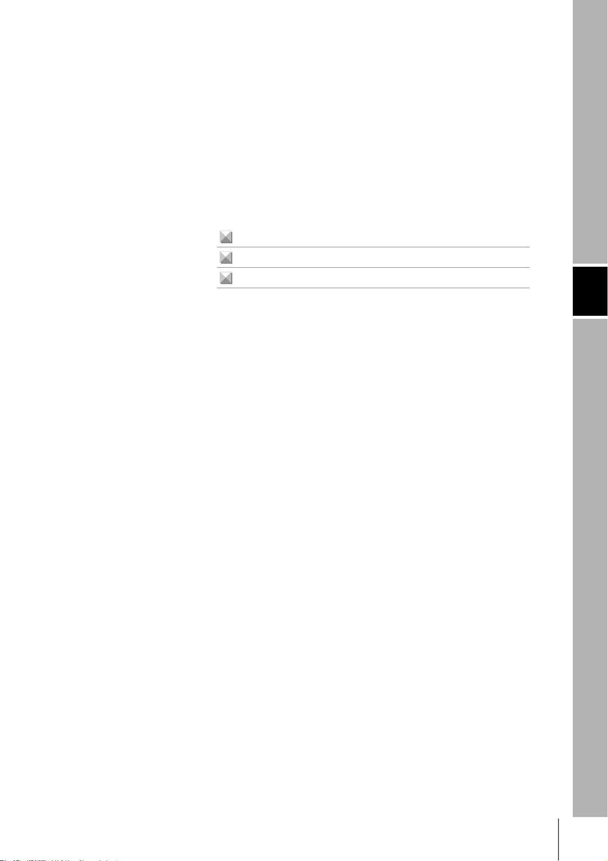
Alert Symbols for Safe Use
The following symbols are used in this manual to indicate precautions that must be observed to ensure safe
use of the V680-HS63, V680-HS52, and V680-HA63B. The precautions provided here contain important
safety information. Be sure to observe these precautions.
The following signal words are used in this manual.
Indicates a potentially hazardous situation which, if not avoided, will result in minor or mod-
WARNING
Meanings of Alert Symbols
erate injury, or may result in serious injury or death. Additionally, there may be significant
property damage.
Introduction
Indicates general prohibitions for which there is no specific symbol.
Warning
WARNING
These Products are not designed to be used either directly or indirectly in applications that detect human
presence for the purpose of maintaining safety. Do not use these Products as a sensing means for protecting human lives.
Regulations and Standards
The V680-HS63, V680-HS52, and V680-HA63 conform to the following overseas regulations and standards.
1. FCC Rules (Federal Communications Commission)
This product complies with Part 15 Subpart C of the FCC Rules.
FCC ID: E4E6CYSIDV6800306
FCC NOTICE
This device complies with part 15 of the FCC Rules. Operation is subject to the following two conditions:
(1) This device may not cause harmful interference.
(2) This device must accept any interference received, including interference that may cause undesired operation.
FCC WARNING
Changes or modifications not expressly approved by the party responsible for compliance could void the user's authority to operate the equipment.
Properly shielded ground cables and connectors must be used for connection to host computer and/or peripherals in
order to meet FCC emission limits.
Ferrite cores (TDK Type ZCAT1730-0730A or its equivalent) must be attached to the cables connecting the power supply and ground to suppress RF interference.
RFID System
User's Manual
3
Page 6
Introduction
Introduction
2. EC Declaration of Conformity
Hereby, OMRON Corporation declares that this RFID System, Antenna V680-HS52, V680-HS63, and Amplifier V680HA63B.Amplifier and Antenna are in compliance with essential requirements and other relevant provisions of Directive
1995/5/EC, and satisfy tests for the appropriate requirements of the following relevant standards.
Radio: EN 300 330-2V1.1.1 (06-2001)
EN 300 330-1V1.3.1 (06-2001)
EMC: EN 301 489-3V1.4.1 (08-2002)
EN 301 489-1V1.4.1 (08-2002)
Safety: EN 61010-1: 2001 (2nd Edition)
Countries of intended use:
Austria, Belgium, Denmark, Estonia, Finland, France, Germany, Greece, Iceland, Ireland, Italy, Liechtenstein, Luxembourg, Netherlands, Norway, Portugal, Romania, Spain, Sweden, Switzerland, United Kingdom
English Hereby, Omron, declares that the RFID System, V680-HS52 Series, V680-HS63 Series, and V680-HA63B Series are in compliance with the essential
Finnish Omron vakuuttaa täten että RFID Säännös, V680-HS52 Series, V680-HS63 Series, V680-HA63B Series tyyppinen laite on direktiivin 1999/5/EY oleellis-
Dutch Hierbij verklaart Omron dat het toestel de RFID Systeem, V680-HS52 ´Serie, V680-HS63 ´Serie, V680-HA63B ´Serie in overeenstemming is met de
French Par la présente Omron déclare que la RFID Système, V680-HS52 Série, V680-HS63 Série, V680-HA63B Série sont conforme aux exigences essentielles
Swedish Härmed intygar Omron att den RFID System, V680-HS52 Serie, V680-HS63 Serie, V680-HA63B Serie stär l överensstämmelse med de väsentliga egen-
Danish Undertegnede Omron erklærer herved, at følgende den RFID System, V680-HS52 Serie, V680-HS63 Serie, 680-HA63B Serie overholder de væsentlige
German Hiermit erklärt Omron, die RFID System, V670-H11 Serie, V680-HS63 Serie, V680-HA63B Serie in Übereinstimmung mit den grundlegenden
Greek
Italian Con la presente Omron dichiara che la RFID Sistema, V680-HS52Serie, V680-HS63 Serie, V680-HA63B Serie sono conforme ai requisiti essenziali ed
Spanish Por medio de la presente Omron declara que el RFID Sistema, V680-HS52 Serie, V680-HS63 Serie, V680-HA63B Serie esta conforme a los requisitos
Portuguese Omron declara que a RFID Sistema, V680-HS52 Série, V680-HS63 Série, V680-HA63B Série ser conforme com os tequisitos essenciais e outras dis-
Romanian
requirements and other relevant provisions of Directive 1999/5/EC.
ten vaatimusten ja sitä koskevien direktiivin muiden ehtojen mukainen.
essentiële eisen en de andere relevante bepalingen van richtlijh 1999/5/EG.
et aux autres dispositions pertinentes de la directive 1999/5/CE.
skapskrav och övriga relevanta bestämmelser som framgår av direktiv 1999/5/EG.
krav og øvrige relevante krav i direktiv 1999/5/EF.
Anforderungen und den anderen relevanten Vorschriften der Richtlinie 1999/5/EG befindet. (BMWi)
ME THN ΠAPOYSA Omron ∆HΛONEI RFID O
ΠPOS TIS OYSIO∆EIS AΠAITHSEIS KAI TIS ΛOIΠES SXETIKES ∆IATAΞEIS THS O∆HΓIAS 1999/5/EK.
alle altre disposizioni pertinenti stabilite dalla direttiva 1999/5/CE.
esenciales y cualesquiera otras disposiciones aplicables o exigibles de la Directiva 1999/5/CE.
posições da Directiva 1999/5/CE.
Prin prezenta, Omron declar c acest V680-HS52,V680-HS63, V680-HA63 este conform cu cerin ele principale çi cu celelalte prevederi relevanate ale
Directivei 1999/5/EC.
’YO’
ΓΗΜΑ, V680-HS52 O’EIPA, V680-HS63 O’EIPA, V680-HA63B O’EIPA SYMMOPF ONETAI
Changes or modifications not expressly approved by the party responsible for compliance could void the user's authority to operate the equipment.
Properly shielded ground cables and connectors must be used for connection to host computer and/or peripherals in
order to meet FCC emission limits.
Ferrite cores (TDK Type ZCAT1730-0730A or its equivalent) must be attached to the cables connecting the power supply and ground to suppress RF interference.
3. Japan Radio Law
Equipment using high frequencies: Inductive Reading/Writing Communications Equipment
Conforming standards: Inductive Reading/Writing Communications Equipment; Standard: ARIB STD-T82
RFID System
4
User's Manual
Page 7

Introduction
Precautions for Safe Use
Be sure to observe the following precautions to ensure safe use of the Products.
1. Do not use the Products in environments with flammable, explosive, or corrosive gasses.
2. Do not attempt to disassemble, repair, or modify any Product.
3. Tighten mounting screws securely.
4. If any cable has a locking mechanism, make sure that it has been locked before using the cable.
5. Do not allow water or pieces of wire to enter from openings in the case. Doing so may cause fire or
electric shock.
6. Turn OFF the Controller power supply before mounting or removing an Antenna or Amplifier.
7. If an error is detected in any Product, immediately stop operation and turn OFF the power supply. Consult
with an OMRON representative.
8. Dispose of the Products as industrial waste.
9. Observe all warnings and precautions given in the body of this manual.
10.Make sure that there is no adverse effect of radio waves on medical equipment.
The Japan Automatic Identification Systems Association (JAISA) guidelines are as follows:
Introduction
These Antennas for RFID devices use radio waves. They may adversely affect medical equipment,
depending on where and in what applications they are used. To minimize the effects of radio waves,
observe the following countermeasure for people with implanted cardiac pacemakers or other medical
devices when using RFID devices:
Do not bring the Antenna for RFID devices any closer than 22 cm to the implanted location of the cardiac pacemaker.
RFID System
User's Manual
5
Page 8

Introduction
Introduction
Precautions for Correct Use
Always observe the following precautions to prevent operation failures, malfunctions, and adverse effects on
performance and equipment.
1. Installation Environment
Do not use the Products in the following locations.
• Locations exposed to corrosive gases, dust, metallic powder, or salts
• Locations not within the specified operating temperature range
• Locations subject to rapid changes in temperature or condensation
• Locations not within the specified humidity range
• Locations subject to direct vibration or shock outside the specified ranges
• Locations subject to spray of water, oil, or chemicals
2. Installation
The Products communicate with Tags using the 13.56-MHz frequency band. Some motors, inverters,
and switching power supplies generate noise that can affect communications with the Tags and cause
errors. If such devices are located near the Tags, always test operation in advance to confirm whether
the system will be affected.
• Observe the following precautions to minimize the effects of normal noise.
(1) Ground all metal objects in the vicinity of the Products to 100 Ω or less.
(2) Do not use the Products near high-voltage or high-current lines.
• Do not use non-waterproof Products in an environment where mist is present.
• Do not expose the Products to chemicals that adversely affect the Product materials.
• When mounting the Products, tighten the screws to the following torques.
V680-HS63: 1.2 N⋅m
V680-HS52: 40 N⋅m
• If multiple Antennas are mounted near each other, communications performance may decrease due
to mutual interference. Refer to Installing Antennas on page 32 and check to make sure there is no
mutual interference.
• Depending on the operating environment, the case surface may become fogged, but basic perfor-
mance will not be affected.
3. Storage
Do not store the Products in the following locations.
• Locations exposed to corrosive gases, dust, metallic powder, or salts
• Locations not within the specified storage temperature range
• Locations subject to rapid changes in temperature or condensation
• Locations not within the specified storage humidity range
• Locations subject to direct vibration or shock outside the specified ranges
• Locations subject to spray of water, oil, or chemicals
4. Cleaning
• Do not clean the Products with paint thinner or the equivalent. Paint thinner or the equivalent will dis-
solve the resin materials and case coating.
RFID System
6
User's Manual
Page 9

Meanings of Symbols
Indicates particularly important points related to a function, including precautions and application advice.
Indicates page numbers containing relevant information.
Introduction
Introduction
Meanings of Symbols
RFID System
User's Manual
7
Page 10

Introduction
Meanings of Symbols
Introduction
MEMO
RFID System
8
User's Manual
Page 11

Introduction
Table of Contents
Safety Precautions 3
Regulations and Standards 3
Precautions for Safe Use 5
Precautions for Correct Use 6
Meanings of Symbols 7
Table of Contents 9
Section 1 Product Overview 11
Features 12
Product Configuration 13
Section 2 Specifications and Performance 15
Introduction
Antennas with Separate Amplifier 16
Amplifier 20
Tags 23
Section 3 Communications Specifications 27
Communications Distances 28
Section 4 Installation 31
Installing Antennas 32
Mounting Amplifiers 33
Installing Tags 37
Section 5 Chemical Resistance 39
Chemical Resistance of the Antennas 40
Revision History 42
RFID System
User's Manual
9
Page 12

Introduction
Introduction
10
RFID System
User's Manual
Page 13

Section 1
Product Overview
Features 12
Product Configuration 13
Section 1 Product Overview
RFID System
User's Manual
11
Page 14
Section 1
Product Overview
Features
Section 1 Features
The V680-series RFID System actively supports many different types of system, such as distributed-control
systems and many-product, small-lot production systems, with non-contact data communications using
electromagnetic induction.
Non-contact Data Communications
The V680 Series uses electromagnetic induction to enable non-contact, bi-directional data communi-
cations between Antennas and Tags.
CRC Used for Transmission Error Detection
A bi-directional 16-bit CRC (Cyclic Redundancy Check) has been added as the error detection method
for wire transmissions between ID Controllers and Antennas, and for wireless transmissions between
Antennas and Tags. This method maintains superior communications reliability even where problems
such as noise occur.
Superior Environmental Resistance and High Reliability
Antennas and Tags now have greater environmental resistance and are not affected by vibration, oil, or
water.
12
RFID System
User’s Manual
Page 15

Product Configuration
Section 1
Product Overview
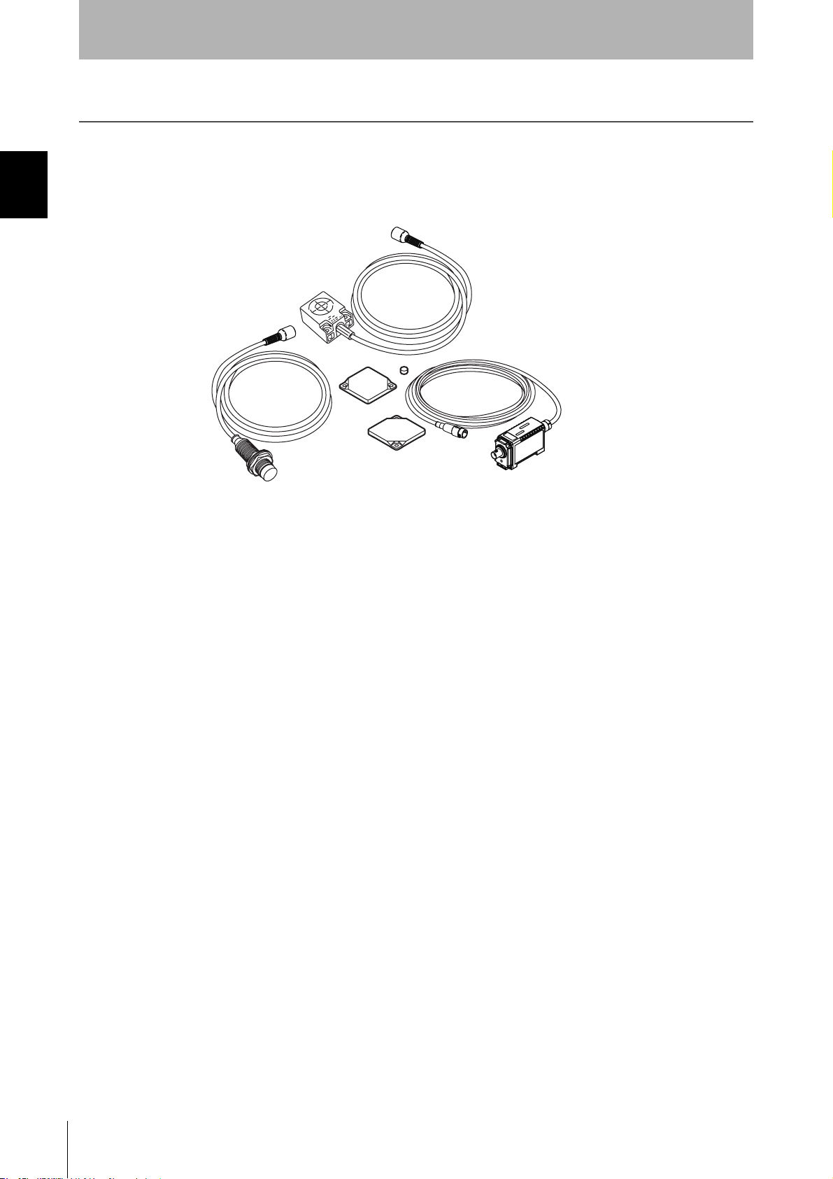
A V680-series RFID System consists of an ID Controller, one or more Amplifiers, one or two Antennas, and
Tags. Select the models suitable for the application.
Personal computer Programmable Controller (PLC)
Host device
RS-232C RS-422 RS-485
V680-CA5D01
ID Controller
V680-HA63B
V680-CA5D02
Section 1 Product Configuration
Tags
V680-D2KF67
Amplifiers
V680-HS52
Antennas with Separate
Amplifier
V680-HS63
V680-D2KF52V680-D2KF67M
RFID System
User’s Manual
13
Page 16

Section 1 Product Configuration
Section 1
Product Overview
MEMO
14
RFID System
User’s Manual
Page 17
Section 2
Specifications and Performance
Antennas with Separate Amplifier 16
Amplifier 20
Tags 23
Section 2 Specifications and Performance
RFID System
User's Manual
15
Page 18

Section 2 Antennas with Separate Amplifier
Section 2
Specifications and Performance
Antennas with Separate Amplifier
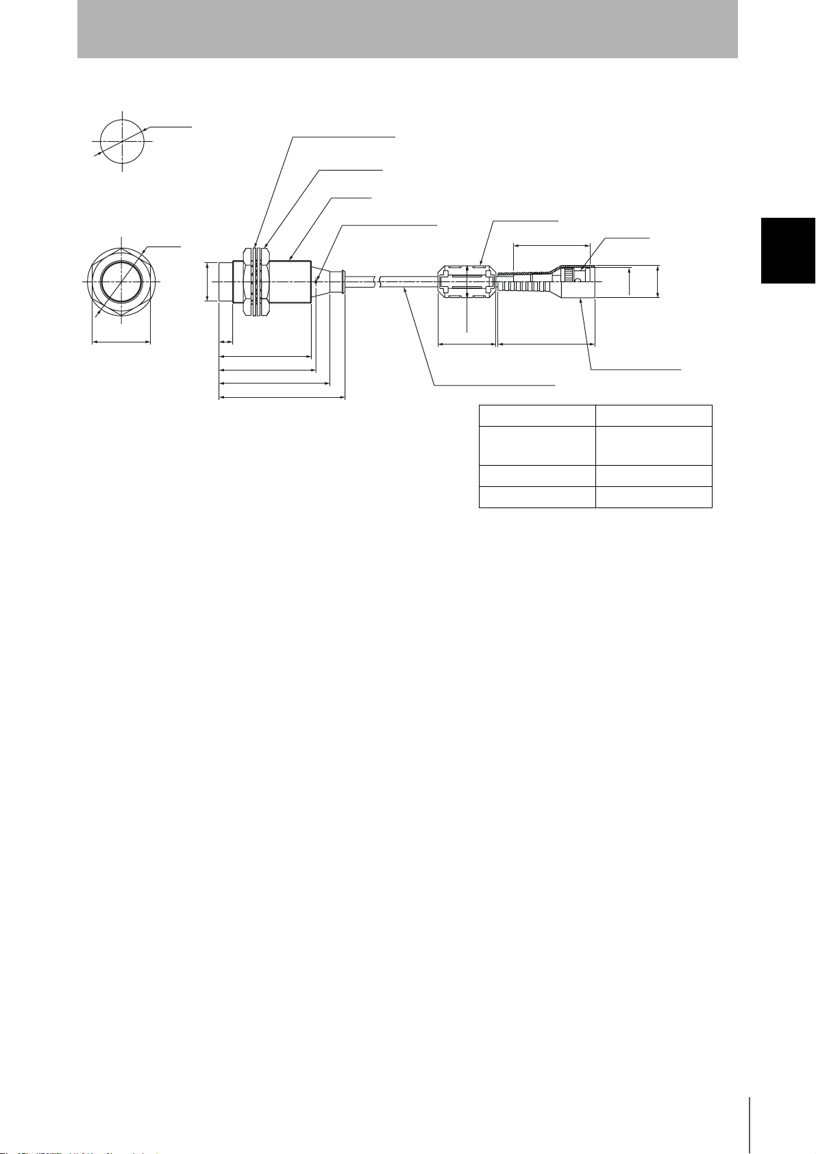
V680-HS63
General Specifications
Item Model V680-HS63-W
(Standard cable, waterproof connector)
Ambient operating
temperature
Ambient storage
temperature
Ambient operating
humidity
Insulation resistance 20 MΩ min. (at 500 VDC) between cable terminals and case
Dielectric strength 1,000 VAC, 50/60Hz for 1 min between cable terminals and case
Degree of protection IP67G (Head)
Vibration resistance Destruction: 10 to 500 Hz, 1.5-mm double amplitude, acceleration: 100 m/s
Shock resistance Destruction: 500 m/s
Dimensions 40 × 53 × 23 mm
Material ABS resin case, epoxy resin filler
Weight Approx. 850 g (with 12.5 m cable)
Cable length Standard lengths of 2 and 12.5 m
−10 to 60°C (with no icing)
−25 to 75°C (with no icing)
35% to 95% (with no condensation)
Note: The connector specifications are IP67 and
IP65.
axis directions (up/down, left/right, and forward/backward) for 11 minutes each
2
, 3 times each in 6 directions (Total: 18 times)
V680-HS63-R
(Flexible cable, non-waterproof connector)
IP67G (Head)
Note: The connectors are not waterproof.
2
, 10 sweeps in each of 3
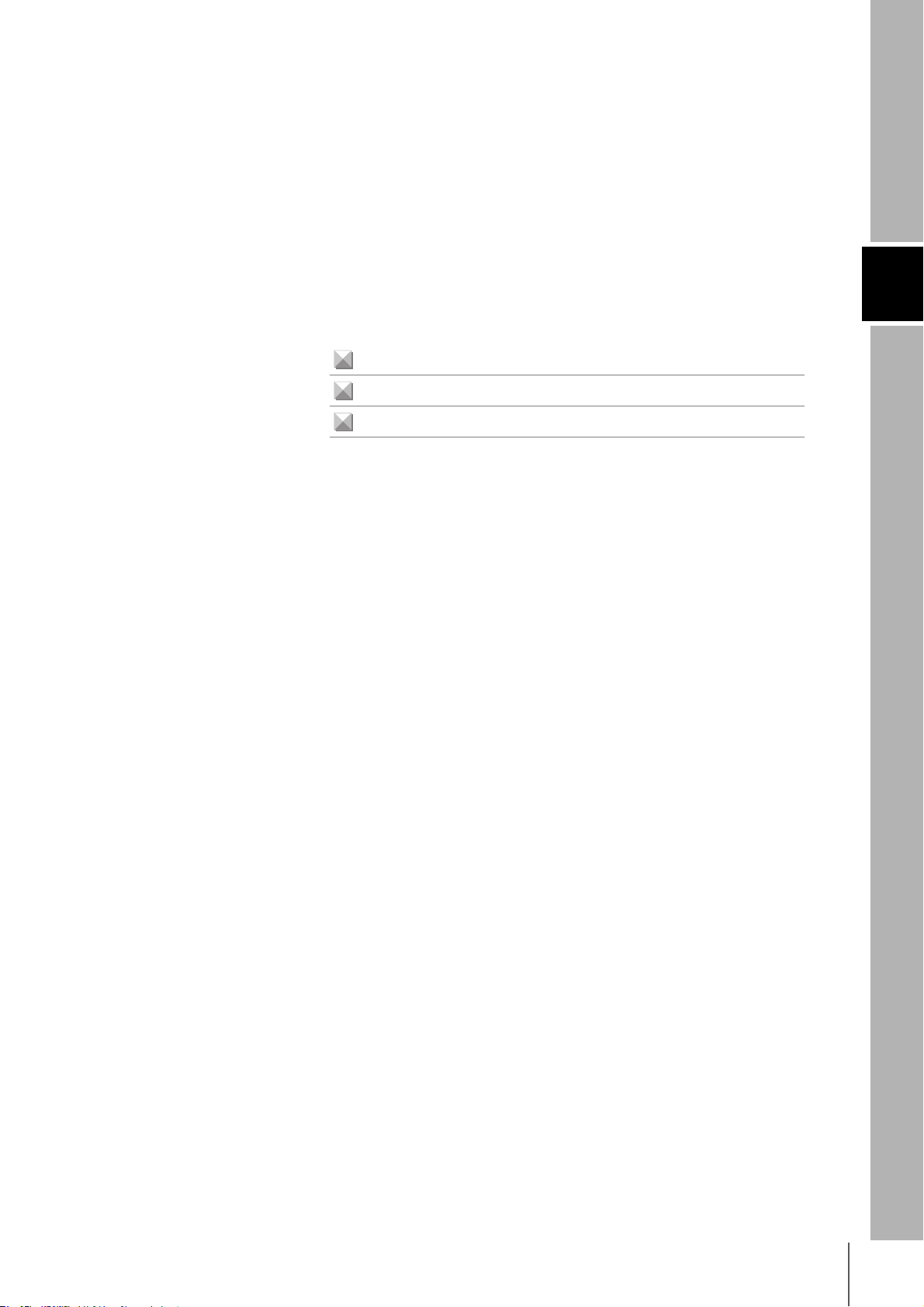
Dimensions
• V680-HS63-W
40
28±0.1
5
5
Operation indicator
23
Note: Mounting Hole Dimensions
Coil center
27 6
53
11
Two, M4 or 4.5 dia. holes
Ferrite core
37
16.5 dia.
Coaxial cable, 5.5 dia.,
standard length: 2 m
5030
Case material ABS resin
Fill resin Epoxy resin
Cable PVC (gray)
Connector
16.5 dia.
14.5 dia.
Insulation cover
(Unit: mm)
16
RFID System
User’s Manual
Page 19
• V680-HS63-R
Specifications and Performance
Ferrite core
(39.5)
Section 2
(Unit: mm)
Connector
40
28±0.1
5
5
Operation indicator
23
Note: Mounting Hole Dimensions
Coil center
27 6
53
11
Two, M4 or 4.5 dia. holes
16.5 dia
5030
Coaxial cable, 5.3 dia.,
standard length: 2 m
Case material ABS resin
Fill resin Epoxy resin
Cable PVC (black)
14.5 dia.
16.5 dia.
Insulation cover
Section 2 Antennas with Separate Amplifier
RFID System
User’s Manual
17
Page 20
Section 2 Antennas with Separate Amplifier
Section 2
Specifications and Performance
V680-HS52
General Specifications
Item Model V680-HS52-W
(Standard cable, waterproof connector)
Ambient operating
temperature
Ambient storage
temperature
Ambient operating
humidity
Insulation resistance 20 MΩ min. (at 500 VDC) between connector terminals and case
Dielectric strength 1,000 VAC, 50/60 Hz for 1 min between connector terminals and case
Degree of protection IP67G (Head)
Dielectric strength
Shock resistance
Dimensions M22 × 65 mm
Material ABS resin, brass, and epoxy resin filler
Weight Approx. 850 g (with 12.5 m cable)
Cable length Standard lengths of 2 and 12.5 m
−10 to 60°C (with no icing)
−25 to 75°C (with no icing)
35% to 95% (with no condensation)
IP67G (Head)
Note: The connector specifications are IP67 and
IP65.
Destruction: 10 to 500 Hz, 1.5-mm double amplitude, acceleration: 100 m/s
axis directions (up/down, left/right, and forward/backward) for 8 minutes each
Destruction: 500 m/s
2
, 3 times each in 6 directions (Total: 18 times)
Note: The connectors are not waterproof.
V680-HS52-R
(Flexible cable, non-waterproof connector)
2
, 10 sweeps in each of 3
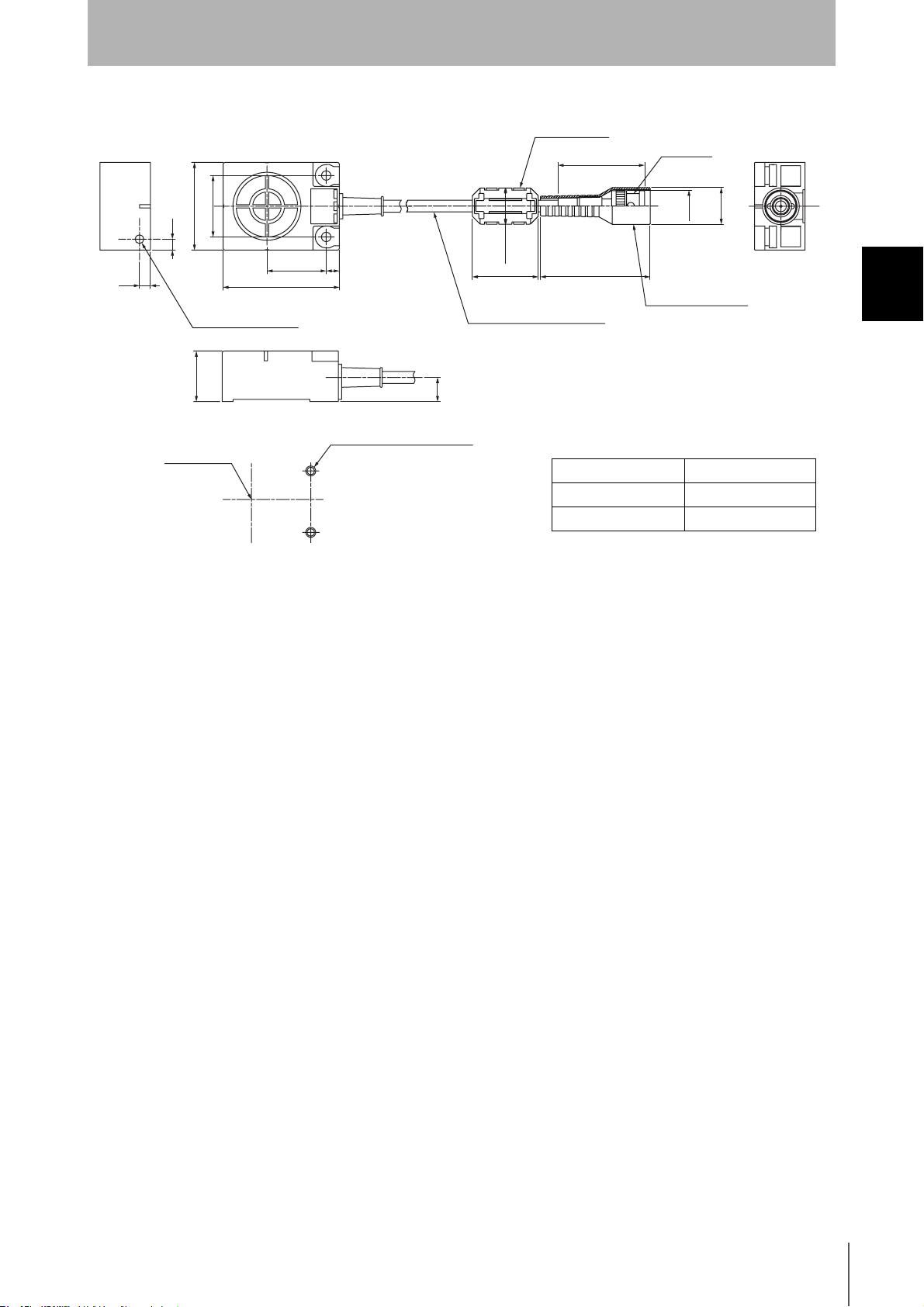
Dimensions
• V680-HS52-W
22.5 dia.
Mounting Hole Dimensions
35 dia.
19.8 dia.
Two toothed washers
Two lock nuts
M22 ´ 1
16.5 dia.
Ferrite core
5030
37
Connector
16.5 dia.
14.5 dia.
Insulation cover
Operation indicator
730
47.6
50
57
65
Coaxial cable, 5.5 dia.,
standard length: 2 m
Case material Brass
Communications
ABS resin
surface
Fill resin Epoxy resin
Cable PVC (gray)
18
RFID System
User’s Manual
Page 21
• V680-HS52-R
22.5 dia.
Mounting Hole Dimensions
Section 2
Specifications and Performance
Two toothed washers
Two lock nuts
M22 ´ 1
35 dia.
19.8 dia.
730
47.6
50
57
65
Operation indicator
Ferrite core
(39.5)
16.5 dia
5030
Coaxial cable, 5.3 dia.,
standard length: 2 m
Case material Brass
Communications
surface
Fill resin Epoxy resin
Cable PVC (black)
Insulation cover
Connector
14.5 dia.
Insulation cover
ABS resin
Section 2 Antennas with Separate Amplifier
16.5 dia.
RFID System
User’s Manual
19
Page 22
Section 2 Amplifier
Section 2
Specifications and Performance
Amplifier
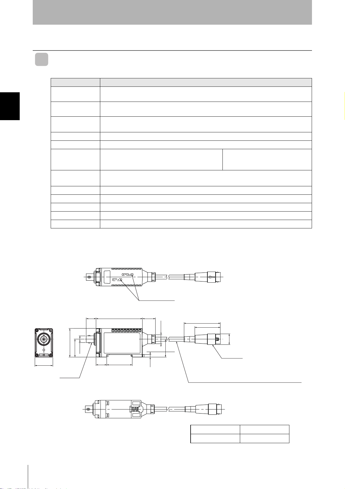
V680-HA63B
General Specifications
Item Model V680-HA63B
Ambient operating
temperature
Ambient storage
temperature
Ambient operating
humidity
Insulation resistance 20 MΩ min. (at 500 VDC) between cable terminals and case
Dielectric strength 1,000 VAC, 50/60 Hz for 1 minute between cable terminals and case.
Degree of protection IP67, IP65 (IEC 60529)
Dielectric strength
Shock resistance Destruction: 500 m/s
Dimensions 25 × 40 × 65 mm (Not including protrusions.)
Materials PC
Weight Approx. 650 g (with 10 m cable)
Cable length Standard lengths of 5 and 10 m
Note: The maximum total cable extension is 50 m (including the Amplifier cable). A maximum of two extension cables can be
connected.
−10 to 55°C ( with no icing)
−25 to 65°C ( with no icing)
35% to 85% (with no condensation)
Note: Not including connector at Controller end.
(When V680-HS63-W or V680-HS52-W is connected)
Destruction: 10 to 500 Hz, 1.5-mm double amplitude, acceleration:100 m/s
axis directions (up/down, left/right, and forward/backward) for 11 minutes each
IP40 (IEC 60529)
(When V680-HS63-R or V680-HS52-R is
connected)
2
, 3 times each in 6 directions (Total: 18 times)
2
, 10 sweeps in each of 3
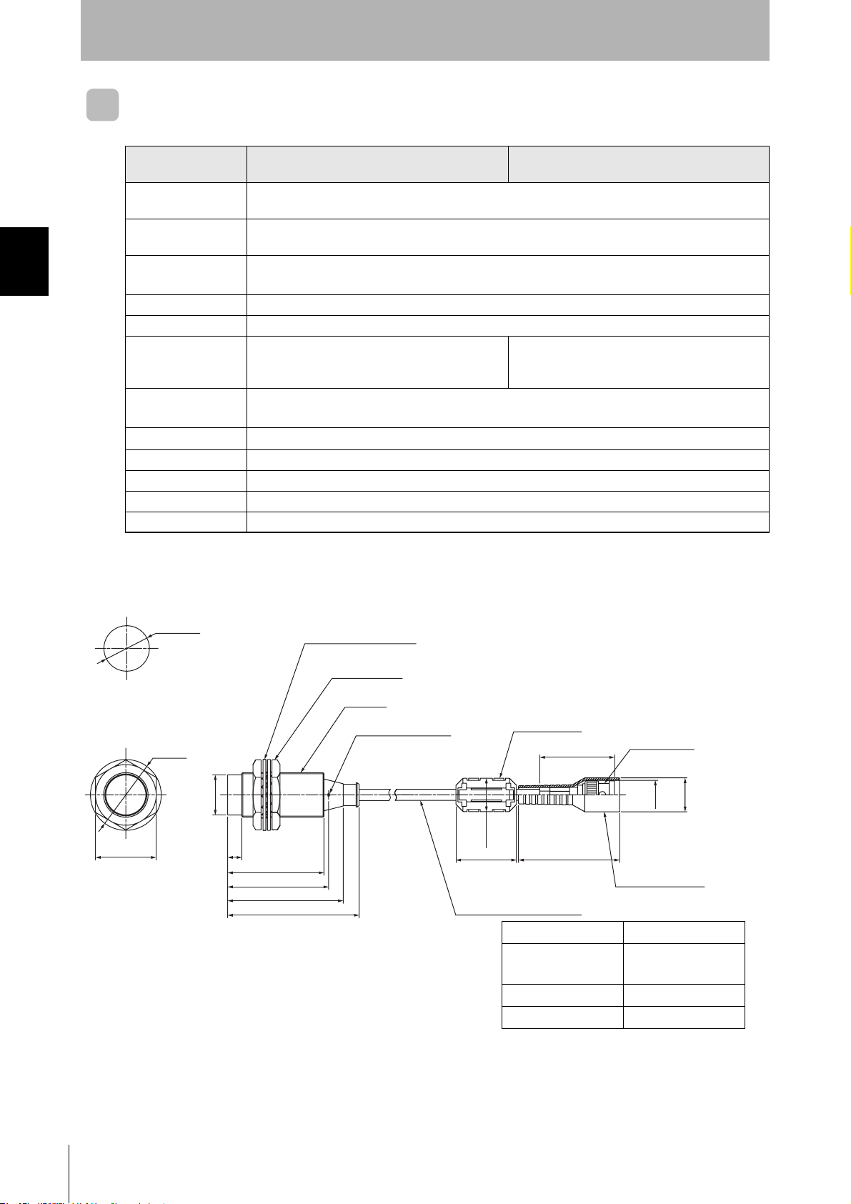
Dimensions
40
25
9.5 dia.
25
Connector
Operation indicator
13.7 65 18
15 35.6
3.5
12.8 dia.
25
51
36
15 dia.
Connector
Round, vinyl-insulated cable (5.8 dia.), standard length: 5 m,
(41/0.16 dia) 2 conductors, (17/0.08 dia.) 8 conductors
Case material PC resin
Cable PVC
20
RFID System
User’s Manual
Page 23

Nomenclature
Section 2
Specifications and Performance
Antenna connection port
RUN
COMM
NORM
ERR
LV6/7D
LV5/7A
LV4/76
LV3/72
Operation indicators
LV2/71
LV1/70
Controller connector
Antenna Connection Port
The Antenna connection port is connected a V680-series Antenna.
Controller Connector
The Controller connector is connected to Antenna connection port on the Controller.
Section 2 Amplifier
Operation Indicators (LEDs)
Name Color Meaning
RUN Green Lit when the power is ON.
Yel-
COMM
NORM Green Lit when communications with a Tag are normal in Normal Communications Mode.
ERR Red Lit when an error occurs in communications with a Tag in Normal Communications Mode.
LV6/7D
LV5 /7A
LV4/76
LV3/72
LV2/71
LV1/70
Lit when a command is being sent.
low
Yel-
Maintenance Mode: Lit at distance level 6.
low
Normal Communications Mode: Lit when a write protection error occurs.
Yel-
Maintenance Mode: Lit at distance level 5 or higher.
low
Normal Communications Mode: Lit when an address error occurs.
Yel-
Maintenance Mode: Lit at distance level 4 or higher.
low
Normal Communications Mode: Lit when a Tag memory error occurs.
Yel-
Maintenance Mode: Lit at distance level 3 or higher.
low
Normal Communications Mode: Lit when a no Tag error occurs.
Yel-
Maintenance Mode: Lit at distance level 2 or higher.
low
Normal Communications Mode: Lit when a verification error occurs.
Yel-
Maintenance Mode: Lit at distance level 1 or higher.
low
Normal Communications Mode: Lit when a Tag communications error occurs.
RFID System
User’s Manual
21
Page 24
Section 2 Amplifier
Section 2
Specifications and Performance
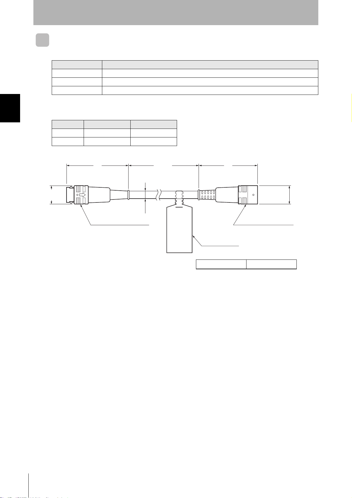
Cables
Specifications
Item Model V700-A43/V700-A44
Number of conductors 10
Insulation resistance 5 MΩ min. (at 500 VDC) between terminals and sheath
Dielectric strength 500 VAC, 1 min
Dimensions
Item Model V700-A43 V700-A44
Length (L1) Approx.10m Approx. 20 m
Weight Approx. 700 g Approx.1,350 g
15 dia.
51 L1
6 dia.
Connector (Controller end))
±100
49
15.5 dia.
Connector (Amplifier end)
Connection label
(Unit: mm)
Casing material PVC
22
RFID System
User’s Manual
Page 25
Tags
Specifications and Dimensions
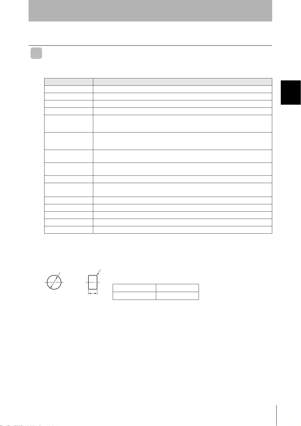
V680-D2KF52
• General Specifications
Item Model 680-D2KF52
Memory capacity 2,000 bytes (user area)
Memory type FRAM
Data backup time 10 years after writing(55°C)
Data overwrite count 10 billion times per address (25°C)
Ambient operating
temperature when
communicating
Ambient operating
temperature when not
communicating
Ambient storage
temperature
Ambient operating
humidity
Degree of protection IP67 (IEC 60529)
Vibration resistance
Shock resistance Destruction: 500 m/s
Dimensions 8 dia. × 5 mm
Materials Case: PPS resin, Fill resin: Epoxy resin
Weight Approx. 0.5 g
Metal countermeasures Yes
Specifications and Performance
−25 to 85°C (with no icing)
−40 to85°C (with no icing)
−40 to 85°C (with no icing)
35% to 95%
Destruction: 10 to 2,000 Hz, 1.5-mm double amplitude, acceleration: 150 m/s
X, Y, and Z directions for 15 minutes each
2
, 3 times each in X, Y, and Z directions (Total: 18 times)
Section 2
2
, 10 sweeps each in
Section 2 Tags
• Dimensions
0
−0.1
8
dia.
R0.2
Case material PPS resin
0
−0.1
5
Fill resin Epoxy resin
RFID System
User’s Manual
23
Page 26

Section 2
Specifications and Performance
V680-D2KF67/67M
• General Specifications
Item Model V680-D2KF67 V680-D2KF67M
Memory capacity 2,000 bytes (user area)
Memory type FRAM
Data backup time 10 years after writing(55°C)
Section 2 Tags
Data overwrite count 10 billion times per address (25°C)
Ambient operating
temperature when
communicating
Ambient operating
temperature when not
communicating
Ambient storage
temperature
Ambient operating
humidity
Degree of protection IP67(IEC 60529)
Vibration resistance
Shock resistance Destruction: 500 m/s
Dimensions 34 × 34 × 3.5 mm
Materials Case: PPS resin
Weight Approx. 6 .5g Approx. 7 g
Metal countermeasures None Yes
−25 to 85°C (with no icing)
−40 to85°C (with no icing)
−40 to 85°C (with no icing)
35% to 95%
Destruction: 10 to 2,000 Hz, 1.5-mm double amplitude, acceleration: 150 m/s
X, Y, and Z directions for 15 minutes each
2
, 3 times each in X, Y, and Z directions (Total: 18 times)
2
, 10 sweeps each in
The V680-D2KF67Mis designed to be mounted directly to metal. The V680-D2KF67 and V680-
D2KF67M markings are shown in the following diagrams.
V680-D2KF67M V680-D2KF67M
METAL
V680-D2KF67M
The side with the markings is the communications surface. Mount the Tag with this side facing the Antenna.
V680-D2KF67
24
RFID System
User’s Manual
Page 27

• Dimensions
V680-D2KF67/67M
0.2
88
40+0.1
-0.5
Section 2
Specifications and Performance
(Unit:mm)
5.2
13.2
16
Two, 3.5 dia.
16
13.2
5.2
4.5
Mounting Hole Dimensions
2
8
32
Two, M3
Section 2 Tags
16
16
40+0.1
-0.5
0.2
8
32
Case material ABS resin
Fill resin Epoxy resin
RFID System
User’s Manual
25
Page 28

Section 2
Specifications and Performance
MEMO
Section 2 Tags
26
RFID System
User’s Manual
Page 29

Section 3
Communications Specifications
Communications Distances 28
Section 3 Communications Specifications
RFID System
User's Manual
27
Page 30

Section 3
Communications Specifications
Communications Distances
V680-D2KF52
Communications Distance Specifications (Certified Performance)
Amplifier Antenna ID Tag Communications distance
V680-HS52 V680-D2KF52
V680-D2KF52
V680-HA63B
V680-HS52
Section 3 Communications Distances
V680-HS63 V680-D2KF52
embedded in metal
(steel)
• Measurement Conditions
V680-D2KF52
Read 0 to 8.0 mm (Axis offset: ±2)
Write 0 to 8.0 mm (Axis offset: ±2)
Read 0 to 3.0 mm (Axis offset: ±2)
Write 0 to 3.0 mm (Axis offset: ±2)
Read 0 to 9.5 mm (Axis offset: ±2)
Write 0 to 9.5 mm (Axis offset: ±2)
V680-HS52
Non-metallic material
V680-HS63
V680-D2KF52
Non-metallic material
(Examples: Resin, plastic, wood, etc.)
Non-metallic material
(Examples: Resin, plastic, wood, etc.)
V680-HS52
Non-metallic material
Steel
V680-D2KF52
28
Non-metallic material
RFID System
User’s Manual
Page 31

Communications Specifications
V680-D2KF67
Communications Distance Specifications (Certified Performance)
Amplifier Antenna ID Tag Communications distance
V680-HS52 V680-D2KF67
V680-HA63B
V680-HS63 V680-D2KF67
• Measurement Conditions
V680-D2KF67
V680-HS52
Read 0 to 17.0 mm (Axis offset: ±2)
Write 0 to 17.0 mm (Axis offset: ±2)
Read 7 to 30.0 mm (Axis offset: ±10)
Write 7 to 30.0 mm (Axis offset: ±10)
V680-HS63
Non-metallic material
(Examples: Resin, plastic, wood, etc.)
Section 3
Section 3 Communications Distances
Non-metallic material
Non-metallic material
(Examples: Resin, plastic, wood, etc.)
Non-metallic material
V680-D2KF67
RFID System
User’s Manual
29
Page 32
Section 3
Communications Specifications
V680-D2KF67M
Communications Distance Specifications (Certified Performance)
Amplifier Antenna ID Tag Communications Distance
V680-HS52
V680-HA63B
V680-HS63
V680-D2KF67M
with metal on back surface (steel)
V680-D2KF67M
with metal on back surface (steel)
• Measurement Conditions
Section 3 Communications Distances
V680-HS52
V680-D2KF67M
Read 0 to16.0 mm (Axis offset: ±2)
Write 0 to 16.0 mm (Axis offset: ±2)
Read 6 to 25.0 mm (Axis offset: ±10)
Write 6 to 25.0 mm (Axis offset: ±10)
V680-HS63
Steel
Non-metallic material
Steel
V680-D2KF67M
Non-metallic material
30
RFID System
User’s Manual
Page 33
Section 4
Installation
Installing Antennas 32
Mounting Amplifiers 33
Installing Tags 37
Section 4 Installation
RFID System
Uer's Manual
31
Page 34
Section 4
Installation
Installing Antennas
V680-HS63
Installation from the Front
Coil center
Two, M4 holes
28+0.2
40
27
53
Section 4 Installing Antennas
Installation from the Back
Insert the nuts that come with the Antenna into sections A.
Two, 4.5 dia. holesCoil center
Nut
Securely tighten screws to a maximum torque of 1.2 N⋅m.
A
28+0.2
27
V680-HS52
Install the Antenna using the nuts and toothed washers that are provided on both sides of the mounting
material, as shown in the diagram below.
32
When the Antenna is mounted to a metal object, the communications distance will be reduced by approximately 10%
compared with mounting to a non-metallic object. For details on the effect of metal surrounding the Antenna, refer to
Effect of Surrounding Metals on the Antenna (Reference) on page 35.
Mounting Hole Dimensions
+0.5
22
dia.
0
Securely tighten the screws to a maximum torque of 40 N⋅m.
RFID System
User's Manual
P. 3 5
Non-metallic material
Nut
Antenna
Toothed washers
Page 35
Mounting Amplifiers
g
g
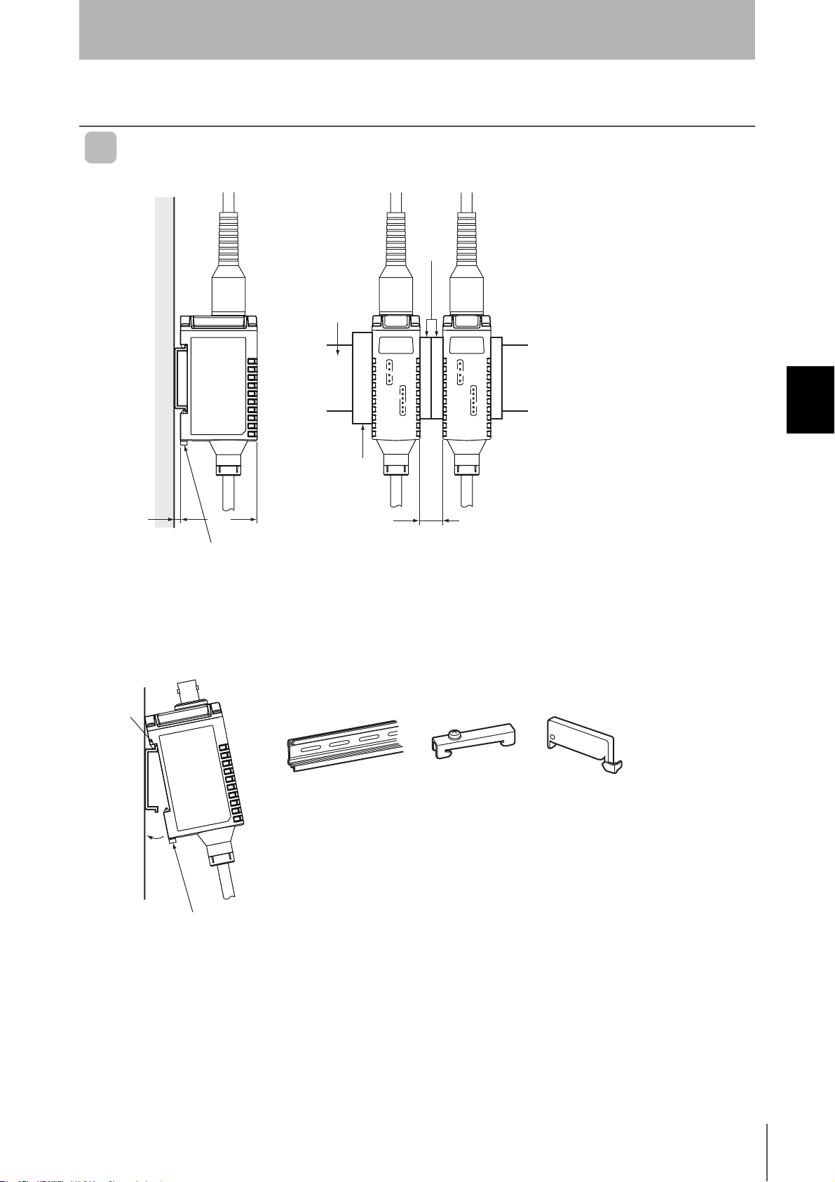
V680-HA63
Mounting to DIN Track
DIN Track
Section 4
Installation
Spacers
Section 4 Mounting Amplifiers
(See note 1.)
Note
A
End Plate
Mountin
40
hook
10 mm min.
(See note 2.)
1. Consider the height of the DIN Track.
2. Provide a space of at least 10 mm (i.e., at least two spacers) and attach them
securely.
DIN Track
PFP-100N2 PFP-M PFP-S
End Plate
Spacer
1. When mounting the Amplifier to a DIN Track, first
hook section A to the Track and then press in
B
2. To remove the Amplifier from the DIN Track, first pull
direction B.
out the mounting hook.
Mountin
hook
RFID System
User's Manual
33
Page 36
Section 4 Mounting Amplifiers
Section 4
Installation
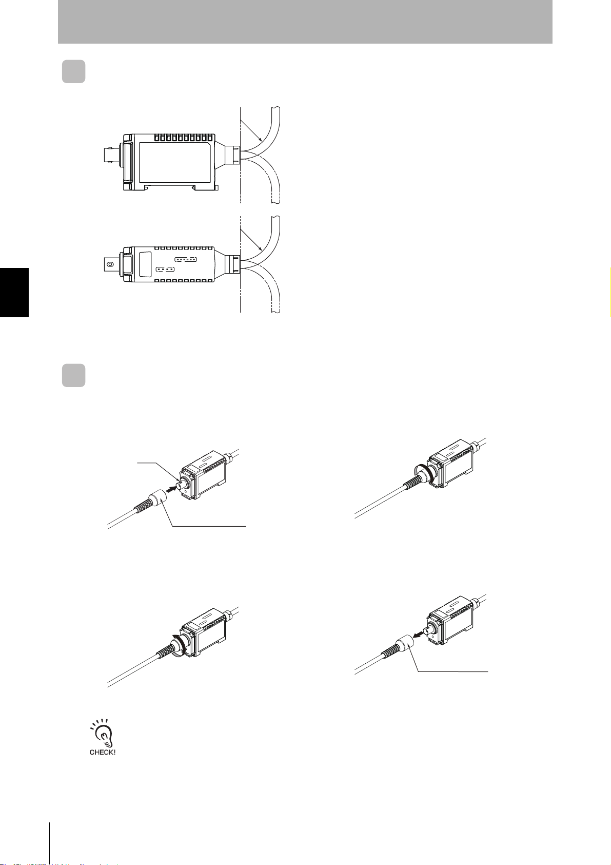
Amplifier Cable Bending Radius
R 35 or
greater
R 35 or
greater
Do not bend the cable past a bending radius of 35 mm.
Attaching/Removing V680-HA63/-HS63/-HS52 Connectors
Attaching the Connector
1. Hold the Antenna connector, align the key,
and insert the connector into the Amplifier
connector.
Key
Antenna connector
Removing the Connector
1. Turn the connector counterclockwise to
release the lock.
2. Turn the connector clockwise to lock it in place.
2. Pull the Antenna connector straight out.
Antenna connector
34
The connector will not come out unless the lock is first released by turning the connector. To remove the cable, release
the lock and pull on the connector. Pulling the cable without releasing the lock may break or damage the cable.
RFID System
User's Manual
Page 37
Section 4
Installation
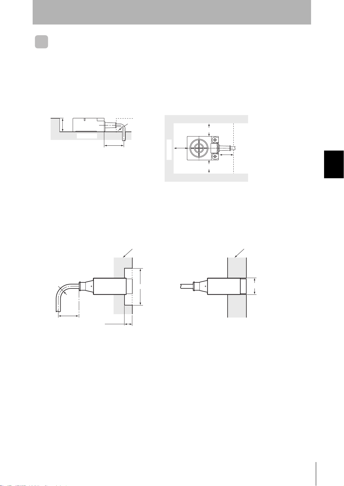
Effect of Surrounding Metals on the Antenna (Reference)
V680-HS63
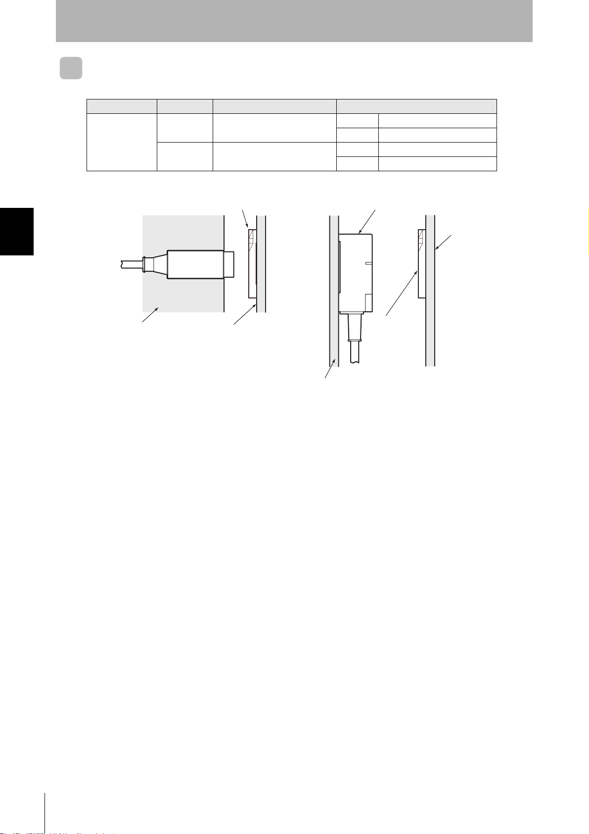
In addition to surface mounting, it is also possible to embed the V680-HS63 in a metal casing to protect
it from being struck by other objects. To prevent malfunctioning, allow a space of at least 30 mm
between the Antenna and the sides of the metal casing. If the space is less than 30 mm, the read/write
distance will be greatly diminished. In addition, the height of metal casing must not exceed that of the
Antenna.
23 mm
max.
Metal casing
60 mm min.
Note
1. Do not bend the cable into a curve
tighter than 22 mm in radius.
R22 min.
30 mm
min.
Metal casing
30 mm min.
30 mm min.
30 mm
min.
2. The communications distance will
be reduced significantly if the
Antenna is installed closer than 30
mm to metal surfaces.
V680-HS52
When embedding the Antenna in metal, be sure the metal does not extend beyond the tip of the
Antenna.
Surrounding metal
(steel)
22 mm dia.
R22 min.
Surrounding metal
(steel)
130 (±65) mm dia. min.
Section 4 Mounting Amplifiers
Antenna
60 min.
15 mm min.
Do not bend the cable into a curve tighter
than 22 mm in radius.
Antenna
If the metal around the Antenna reaches the coil surface, the
communications distance will be reduced by approximately
50% compared with mounting to a non-metallic surface.
Communications
distance
reduced by 50%.
RFID System
User's Manual
35
Page 38
Section 4 Mounting Amplifiers
Section 4
Installation
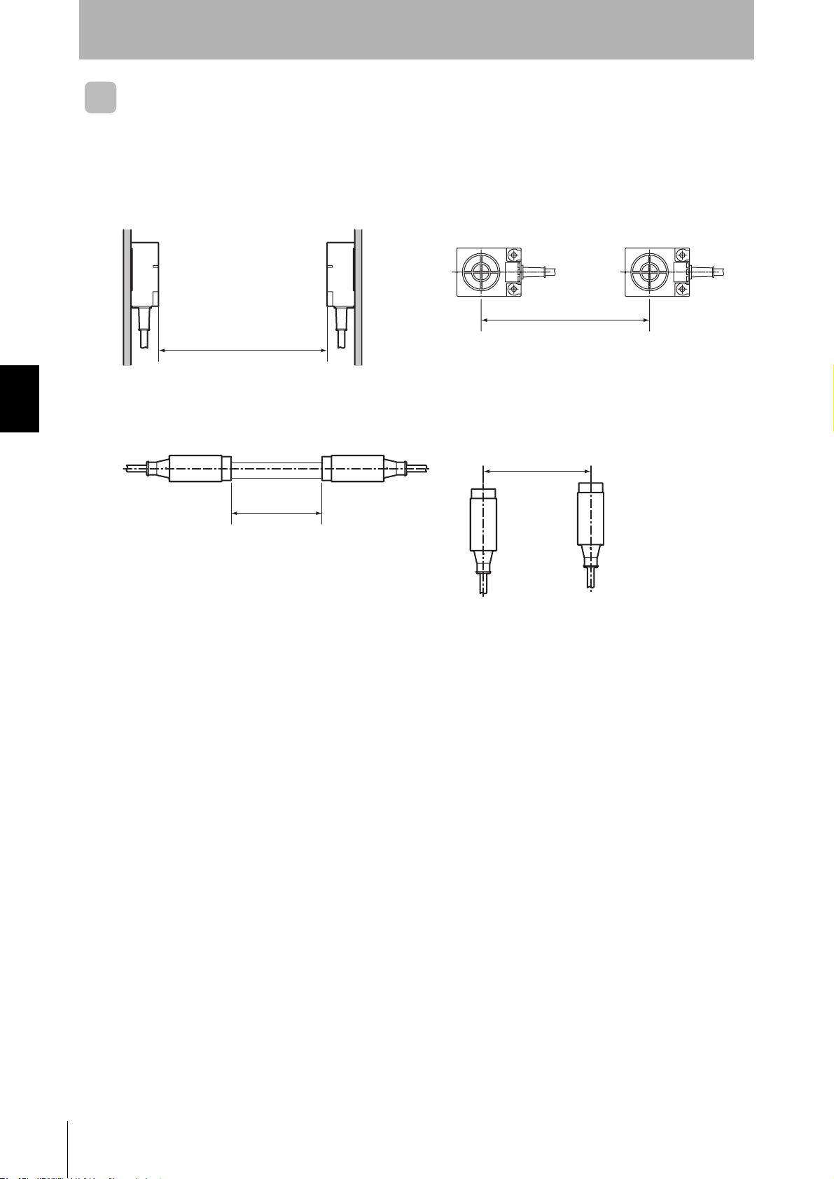
Mutual Interference between Antennas (Reference)
To prevent malfunctioning due to mutual interference when using more than one Antenna, leave suffi-
cient space between them as shown in the following diagrams.
V680-HS63
• Installing the Antennas Facing Each Other
420 mm min.
V680-HS52
• Installing the Antennas Facing Each Other
• Installing the Antennas in Parallel
260 mm min.
• Installing the Antennas in Parallel
120 mm min.
100 mm min.
36
RFID System
User's Manual
Page 39
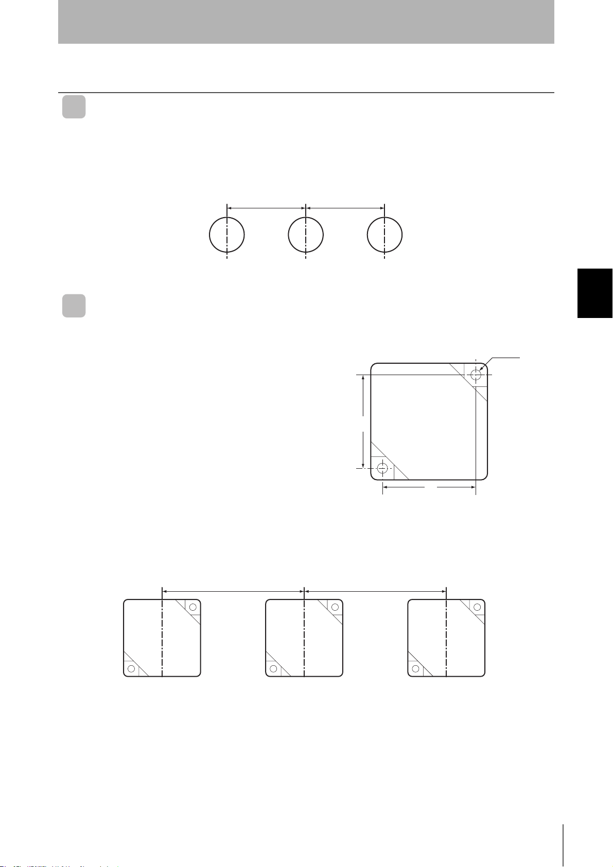
Installing Tags
V680-D1KP52MT
Mutual Interference with Tags (Reference)
Provide the mounting distances indicated below to prevent malfunctions due to mutual interference
when using more than one Tag.
25 mm min. 25 mm min.
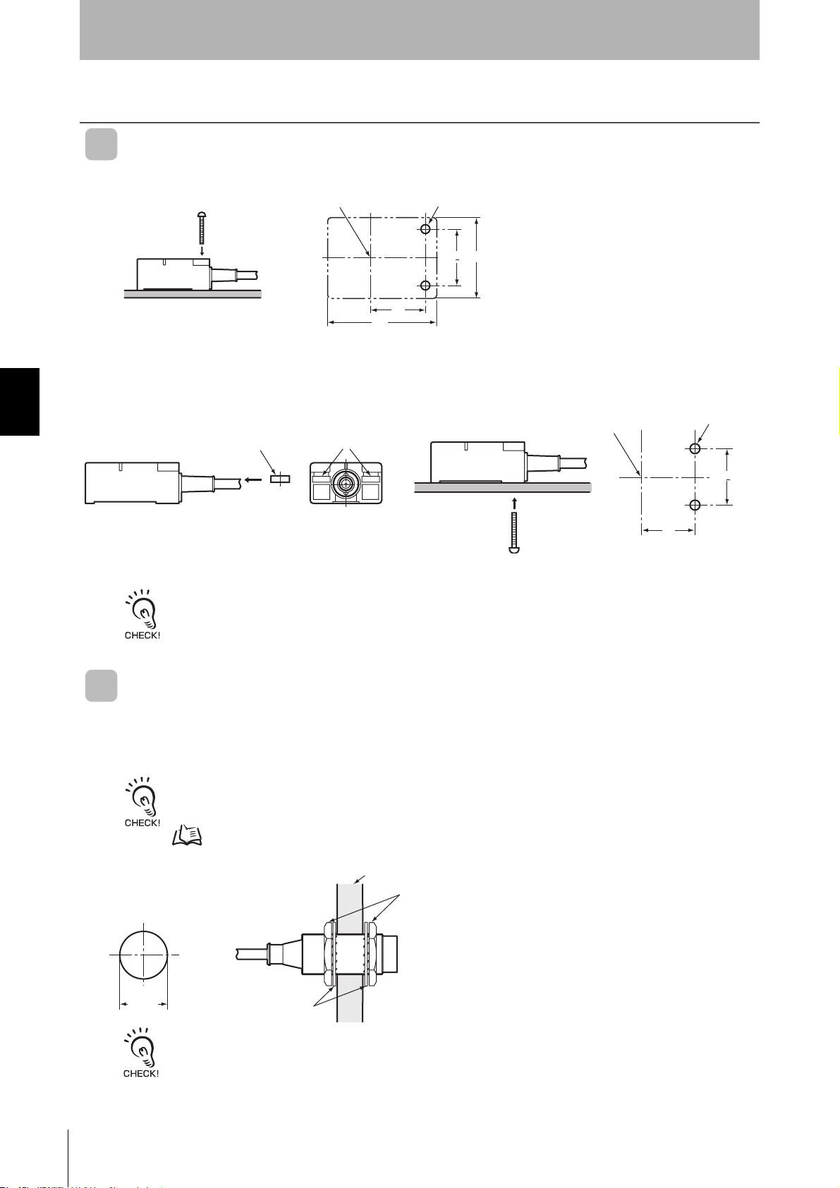
V680-D2KF67
Section 4
Installation
Section 4 Installing Tags
Tag Installation Direction
Secure the Tag with M3 screws. Tighten the screws to a
torque of 0.3 to 0.5 N·m.
32
32
Two, M3
Mutual Interference with Tags (Reference)
To prevent malfunctioning due to mutual interference when using more than one Tag, leave sufficient
space between them as shown in the following diagram.
200mm min.
200mm min.
RFID System
User's Manual
37
Page 40

Section 4
Installation
V680-D2KF67M
Tag Installation Direction
Mount the V680-D2KF67M to a metal surface, and
secure the Tag with M3 screws. Tighten the screws to a
torque of 0.3 to 0.5 N
⋅m.
32
32
Section 4 Installing Tags
Mutual Interference with Tag (Reference)
To prevent malfunctioning due to mutual interference when using more than one Tag, leave sufficient
space between them as shown in the following diagram.
Two, M3
120mm min.
120mm min.
38
RFID System
User's Manual
Page 41

Section 5
Chemical Resistance
Chemical Resistance of the Antennas 40
Section 5 Chemical Resistance
RFID System
User's Manual
39
Page 42

Section 5
Chemical Resistance
Chemical Resistance of the Antennas
Applicable Models
V680-HS63-W/R V680-HS52-W/R
ABS resin is used for case material and epoxy resin for filling material. Refer to the following lists and do not
use chemicals that affect ABS and epoxy resin.
Chemicals That Cause Deformations, Cracks, Etc.
ABS resin Epoxy resin
Trichlene, acetone, xylene, toluene, gasoline, creosol,
methylene chloride, phenol, cyclohexane, aqua regia,
chromic acid, sulfuric acid (90% RT), methyl ethyl
ketone, aniline, nitrobenzine, monochlorobenzine,
pyridine, nitric acid (60% RT), formic acid (80% RT)
Aqua regia, chromic acid, sulfuric acid (90% RT),
nitric acid (60% RT), ammonia solution, acetone,
methylene chloride, phenol
Section 5 Chemical Resistance of the Antennas
Chemicals That May Cause Discoloration, Swelling, Etc.
ABS resin Epoxy resin
Hydrochloric acid, alcohol, Freon, sodium hydroxide,
hydrogen peroxide, benzine, sulfuric acid (10% RT),
nitric acid (10% RT), phosphoric acid (85% RT),
ammonia solution
Sulfuric acid (10% RT), nitric acid (10% RT), hydrochloric acid (30% RT), acetic acid (50% RT), oxalic acid,
calcium hydroxide, benzine, creosol, alcohol, cyclohexane, toluene, xylene, benzine, grease
Chemicals That Do Not Affect ABS Resin or Epoxy Resin
ABS resin Epoxy resin
Ammonia, kerosine, mineral oil, developer, Yushiroken
S50, Chemi-Cool Z, Velocity No. 3, Yushiroken EEE30Y, petroleum, grease, acetic acid, oxalic acid, calcium hydroxide, phosphoric acid (30% RT), hydrochloric acid (10% RT), potassium hydroxide
Note: The above results are from tests conducted a room temperature (23°C). Even if the chemicals
do not affect the ABS or epoxy resins at room temperature, they may affect the resins at higher
or lower temperatures. Check the chemicals carefully in advance.
Ammonia, hydrochloric acid (10% RT), potassium
hydroxide, petroleum, gasoline, Yushiroken S50,
Chemi-Cool Z, Velocity No. 3, Yushiroken EEE-30Y
40
RFID System
User’s Manual
Page 43

MEMO
Section 5
Chemical Resistance
Section 5 Chemical Resistance of the Antennas
RFID System
User's Manual
41
Page 44

Revision History
A manual revision code appears as a suffix to the catalog number at the bottom of the front and rear pages.
Cat. No.: Z248-E1-01
Revision code
Revision code Date Revised contents
01 October 2006 Original production
42
RFID System
User's Manual
Page 45

6 ⊆
ΡΦΙ∆ Σψστεµ
[Υ[Ψ}ϕΑ
43
 Loading...