

Page 1

Electromagnetic Coupling Type RF-ID System
V670 Series
User’s Manual
ID Controller, Antenna, and ID Tag
ID Controller
Model V670-CD1D
Antenna
Model V670-H11
ID Tag
Model V670-D13F03
Catalog No. SCLB-702
Page 2

Introduction
Thank you very much for choosing the electromagnetic coupling type RF-ID system V670 Series. The V670 Series has been developed
by OMRON, based on the advanced technology and extensive experience. This user’s manual describes the functions, performance and
usage of V670 Series.
When you use the V670 Ser ies, follow the instructions below:
• Read this user’s manual with care, underst and the V670 Series fully and use it appr opriately.
• Keep this user’s manual handy.
Notes on use
When you use the V670 Series in the following environments, we would like you to operate it within the rating and functions, take
safety measures such as fail-safe system and consult our person in charge.
(1) Use in an unsuitable condition or environment which is not described in the user’s manual
(2) Use for nuclear energy control, railroad, aeronautica l system, car, combustion equipmen t, medical equipment, amusement
facility, safety device, etc.
(3) Use for application which may have a great influence on people’s lives and property and must be executed safely in particu-
lar.
Page 3

Notes on safety
For the safety, be sure to follow the instructions below:
1. Do not operate this device in any flammable, explosive or corrosive gas environment.
2. Do not disassemble, repair nor remodel this device.
3. Tighten the base lock screws and terminal block screws completely.
4. Be sure to use wiring crimp terminal of a specified size.
5. If any cable has a locking mechani s m, be sure to check that it has been loc ked before using it.
6. The DC power supply must meet the following items:
(1) Such DC power supply must be used for the V670 Series onl y and must not be connected to any other devices nor apparatuses.
(2) Voltage of such DC power supply must be within the specified rating (24 VDC+10%-10%).
7. Be sure to follow any other warnings, cautions and notices mentioned in this manual.
Notes on usage
1. Do not install Model V670-CD1D in the following areas:
• Place exposed to the direct sunlight.
• Humid place where moisture condensat ion may occur.
• Place affected by vibration or impact.
2. Preliminary check of installation site.
This device use s the freq uen cy ba nd 13 .56 MH z to co mmu nica te w ith a tag . This f requ enc y ban d 13.5 6 MHz is used also as the ISM
band (one of frequencies assigned to med ical or indu stria l heater; an appl icati on must be file d for instal lati on). So, such heat er may
affect the communication with a tag or may damage the tag, if the heater is located near this device. If you must this device near such
heater, we would like you to check the influence in advance. To minimize general influence of noise, follow the instructions below:
• Ground any metallic material located around this device according to Class D (Class III).
• Wire this device keeping away f rom high voltage and h eavy current.
3. Be sure to ground any ground terminal according to Class D (conventional Class III). Otherwise, performance may deteriorate.
4. Cleaning of Model V670-D13F03, Model V670-H11 and Model V670- CD1D.
• Do not use any thinner. Resin material and case paint are dissolved by thinner.
Page 4
Manual Revision History
A manual revision history code is added to the end of catalog number shown at the left lower part of front cover
and back cover
Catalog No. SCLB-702!
Revision
Code
-- October 2000 First Edition
Date of
Revision
Reason of Revision / Revised Page
!
!!
Revision code
Page 5

Contents
Chapter 1 Features and System Configuration
1-1 Features ..........................................................................................................................1-1
1-2 System Configuration.....................................................................................................1-2
Chapter 2 Specifications and Performance
2-1 Controller........................................................................................................................2-1
2-1-1 Component Names and Functions..................................................................................................... 2-1
2-1-2 General Specifications.......................................................................................................................2-3
2-1-3 Perfo rmance Sp ecifications............................................................................................................... 2-3
2-1-4 Communication Specifications..........................................................................................................2-4
2-1-5 I/O Specifications ..............................................................................................................................2-4
2-1-6 Example of Wiring.............................................................................................................................2-5
2-1-7 Outside Dimension ............................................................................................................................2-6
2-2 Antenna...........................................................................................................................2-7
2-2-1 Specifications.....................................................................................................................................2-7
2-2-2 Outside Dimension ............................................................................................................................2-7
2-3 Tag..................................................................................................................................2-8
2-3-1 Specifications.....................................................................................................................................2-8
2-3-2 Outside Dimension ............................................................................................................................2-8
2-3-3 Memory Map .....................................................................................................................................2-9
2-4 Cable.............................................................................................................................2-10
2-4-1 Specifications...................................................................................................................................2-10
2-4-2 Outside Dimension ..........................................................................................................................2-10
2-5 Communication Range Specifications .........................................................................2-11
2-5-1 Communication Area (Reference)................................................................................................... 2-11
2-5-2 Operation Time (Reference)............................................................................................................ 2-12
2-5-3 Traffic and Passing Speed (Reference)............................................................................................ 2-14
Chapter 3 Setting And Installation
3-1 Controller........................................................................................................................3-1
3-1-1 Switch Setting....................................................................................................................................3-1
3-1-1-1 How to Open Cover.................................................................................................................3-1
3-1-1-2 How to Set ...............................................................................................................................3-2
3-1-1-3 Setting List............................................................................................................................... 3-2
3-1-1-4 Setting Node Number Setup Switch........................................................................................3-3
3-1-1-5 Setting a Dip Switch ................................................................................................................ 3-4
3-1-2 Installation Site .................................................................................................................................. 3-6
3-1-3 How to Install .................................................................................................................................... 3-7
3-1-4 How to Connect Antenna...................................................................................................................3-8
3-1-5 How to Connect Extension Cable And How To Extend Antenna.....................................................3-9
3-1-6 How to Wire.......................................................................................................................................3-9
Page 6

Chapter 4 Functions
Contents
3-1-6-1 Wiring Power Supply And Grounding Cable ........................................................................3-10
3-1-6-2 Wiring Reset Signal ...............................................................................................................3-10
3-1-6-3 Wiring Output Signal.............................................................................................................3-11
3-1-7 Connecting RS-232C Interface........................................................................................................3-12
3-2 Antenna ........................................................................................................................3-16
3-2-1 Installation Site ............................ ...... ...... ............................................. ...........................................3-16
3-2-2 How To Install..................................................................................................................................3-16
3-3 Tag................................................................................................................................3-17
3-3-1 Installation Site ............................ ...... ...... ............................................. ...........................................3-17
3-3-2 How to Install...................................................................................................................................3-17
Chapter 4 Functions
4-1 Communication Designation Function...........................................................................4-1
4-1-1 Designation Of Command Trigger System Communication (ST).....................................................4-1
4-1-2 Designation of Automatic System Communication (SA/RA/PA) .....................................................4-2
4-1-3 Designation of External Trigger System Communication (SI/RI/PI)................................................4-3
4-2 Tag Designation Function...............................................................................................4-5
4-3 Operation Mode..............................................................................................................4-6
4-4 Operation Parameter Setting...........................................................................................4-8
4-4-1 Communication Res tri ction Time......................................................................................................4-8
4-4-2 Character Interval Monitoring Time..................................................................................................4-8
4-4-3 Response Ready Time........................................................................................................................4-9
4-5 Memory Check Function..............................................................................................4-10
4-6 Write Protect Function..................................................................................................4-11
Chapter 5 Control From Host Device
5-1 Controller Operation Status ...........................................................................................5-1
5-2 Command Response Format ..........................................................................................5-2
5-3 Command Response Flow..............................................................................................5-6
5-4 Command List................................................................................................................5-7
5-5 Communication Designation List...................................................................................5-8
5-6 Communication Command.............................................................................................5-9
Page 7

Contents
5-6-1 Read (RD)........................................................................................................................................5-10
5-6-2 Write (WT)....................................................................................................................................... 5-11
5-6-3 Computation Write (CW) ................................................................................................................ 5-12
5-6-4 Data Fill (DF) .................................................................................................................................. 5-13
5-6-5 Memory Check (MD) ...................................................................................................................... 5-14
5-6-6 Tag Function Designation (TF)........................................................................................................5-15
5-6-7 ID Read (ID)....................................................................................................................................5-16
5-7 Communication Subcommand .....................................................................................5-17
5-7-1 Command Processing Abort (AA)................................................................................................... 5-17
5-7-2 Polling Query (PC) .......................................................................................................................... 5-17
5-8 Controller Control Command.......................................................................................5-18
5-8-1 Operation Mode Change (MO)........................................................................................................ 5-18
5-8-2 Data Retransmission (RR)............................................................................................................... 5-18
5-8-3 Reset (XZ)........................................................................................................................................ 5-19
5-8-4 Controller Control (CC)...................................................................................................................5-19
5-8-5 Operation Condition Setting (SE).................................................................................................... 5-20
5-8-6 Parameter Setting (SP)..................................................................................................................... 5-22
5-9 Host Command.............................................................................................................5-23
5-9-1 Test (TS) ............................... ............................................. .............................................................. 5-23
5-9-2 Version Information (VS)...................... ..... ...... ............................................. ..................................5-23
5-10 Termination Code List..................................................................................................5-24
5-11 Example Of Communication Program.........................................................................5-25
Chapter 6 How To Use Self-Execution Mode
6-1 Available Conditions ......................................................................................................6-1
6-2 Setting Procedure ...........................................................................................................6-2
6-3 Example Of Setting ........................................................................................................6-3
Chapter 7 How to Use Programming Console
7-1 Component Name...........................................................................................................7-1
7-2 Outside Dimension.........................................................................................................7-2
7-3 Connection of Programming Console............................................................................7-3
7-3-1 Inserting Key Sheet............................................................................................................................7-3
7-3-2 Connecting Cable............................................................................................................................... 7-4
Page 8

Chapter 8 From Startup To Run
Contents
7-4 How to Use.....................................................................................................................7-5
7-5 Functions ........................................................................................................................7-6
7-5-1 Programming Console Function List.................................................................................................7-6
7-5-2 How to Operate..................................................................................................................................7-7
7-5-2-1 Password Input Screen.............................................................................................................7-7
7-5-2-2 Changing Operation Mode.......................................................................................................7-7
7-5-2-3 Accepting Key in Initial Screen of Monitor Mode..................................................................7-8
7-5-2-4 Accepting Key in Initial Screen of Run Mode......................................................................... 7-9
7-5-3 Displaying Details of Setting...........................................................................................................7-10
7-5-4 Address Setting................................................................................................................................7-12
7-5-4-1 For Reading............................................................................................................................7-12
7-5-4-2 For Writing.............................................................................................................................7-12
7-5-5 Data Setting......................................................................................................................................7-13
7-5-6 Reading/Writing Data ......................................................................................................................7-13
7-5-6-1 Reading ..................................................................................................................................7-13
7-5-6-2 Reading Again........................................................................................................................7-14
7-5-6-3 Writing ...................................................................................................................................7-15
7-5-6-4 Writing Again.........................................................................................................................7-15
7-5-7 Test ...................................................................................................................................................7-16
7-5-7-1 Setting Communication Mode...............................................................................................7-16
7-5-7-2 T est Reading................................... ............................................. ...........................................7-16
7-5-7-3 T est Writing.................................... ..... ...... ............................................. ................................7-16
7-5-8 Reading Latest Error Information....................................................................................................7-17
7-5-9 Statistic Error Information ...............................................................................................................7-18
7-5-10 Execution Monitor .................................................................................................................7-19
Chapter 8 From Startup To Run
8-1 Trial Operation ...............................................................................................................8-1
8-2 Diagnosis Function.........................................................................................................8-2
8-3 Errors and Countermeasures...........................................................................................8-3
8-4 Maintenance and Inspection...........................................................................................8-4
8-5 Troubleshooting..............................................................................................................8-5
Chapter 9 Characteristic Data Depending on Operating Condition
(Reference)
9-1 Influence of Back Metal of Antenna (Reference) ..........................................................9-1
9-2 Mutual Interference between Antennas (Reference)......................................................9-2
9-3 Mutual Interference between Tags (Reference) .............................................................9-3
Page 9

9-4 Influence of Back Metal of Tag (Reference)..................................................................9-4
9-5 Influence of Tag Angle (Reference)...............................................................................9-5
9-6 Chemical Resistance of Tag (Reference)........................................................................9-6
Appendix
Appendix 1 JIS8 Unit Code List (ASCII Code List) ................................................Appendix-1
Appendix 2 Order Format List..................................................................................Appendix-2
Appendix 3 Protective Structure ...............................................................................Appendix-3
Contents
Page 10

Structure of This Manual
Chapter 1 Features and System Configuration
Chapter 2 Specifications and Performance
Chapter 3 Setting and Installation
Chapter 4 Functions
Chapter 5 Control from Host Device
Chapter 6 How to Use Self-Execution Mode
Chapter 7 How to Use Programming Console
Chapter 8 From Startup to Run
Chapter 9 Characteristic Data (Reference) Depending on
Operating Cond ition
Appendix
Page 11

Chapter 1 Features and System Configuration
1-1 Features
The V670 Series is the electromagnetic coupling type RF-ID system which has achieved fast, long-life and high-performance communication. This ID syste m is the most suitable for process control of high-speed line and traffic control of moving object in a plant and an
application that information must be updated frequently in a process.
Model V670-CD1D
Model V670-D13F03
• Model V670-CD1D (ID controller, referred to as "Controller")
Model V670-CD1D connects to a pe rsonal computer (referred to as " PC") and/or programmable con troller (PLC) and controls the
RF-ID system.
Model V670-CD1D has a ge neral-purpose I /O terminal and a f unction to judg e and process inde pendently (Self-E xecution mode)
and, therefore, a very fast system can b e configured for simple process only without any host device.
• Model V670-H11 (Antenna)
Model V670-H11 is a waterpro of antenna (stand ard antenna) with di mensions of 4 x 5.3 cm. Mo del V670-H11 can achieve the
communication area of 20 mm in combination with model V670-D13F03.
Model V670-H11 has a very fast comm unication performance and can transfer 12 bytes of data in appr oximately 5 ms.
• Type V670-D13F03 (ID tag, referred to as "Tag")
Type V670-D13F03 is a waterproof tag which has 1 28 bytes of memory capaci ty with dimensions of 40 x 40 mm. Model V670D13F03 uses high-performance nonvolatile memory called Ferroelectric RAM (FeRAM) as internal memory. So, memory life is
semi-permanent. (The memory can be accessed one billion times.)
Model V670-H11
• Easy to use
By connecting the programming console model C200H-PRO27 (unbundled, referred to as "ProCon") to the Controller via the special
cable model V700-P10 (unbundled), the system operation status and error log information can be read. This is useful for system startup and maintenance at a working site.
Ferroelectric RAM (FeRAM)
Ferroelectric RAM is one of nonv ol ati le RAMs and d ata can be writte n into a nd read from it fa ster than con ve nt ion al mem ory (such
as EEPROM and flash ROM). Data can be written into the ferroelectric RAM semi-permanently.
While any conventional RAM cann ot hold data if no thi ng is written in to it fo r a sp ecified perio d (app rox im a tely 1 0 ye ars), th e ferroelectric RAM can hold data if anyt hing is writ ten into or read from it. So , the ch aracteristic of fe rroele ctric RAM is very ex cellent in
data-holding performance.
1-1
Page 12

1-2 System Configuration
• Example of Model V670-CD1D system configuration
Model V670-CD1D contains a serial interface based on RS-232C and can connect easily to a general-purpose PC and programmable
controller (PLC). Model V670-CD1D has a comman d execution mo de and self-ex ecution mode as an operation mo de and control s
the communication to a tag according to the in stru ctions from a host device (in the command execution mod e) or t he registered conditions (in the self-execution mode).
<Hose Devices>
Desktop PC
Notebook PC
Model V670-CD1D
Model V670-A4
(Only when extension cable is used)
Programmable Controller
Model V700-P10
Model C200H-PRO27
!
1-2
Model V670-H11
Tag
Page 13

Chapter 2 Specifications and Performance
2-1 Controller
2-1-1 Component Names and Functions
• Model V670-CD1D
(1)Node number setup switch
(2)Dip switch
(3)LED display
(4)Cover
(5)Connecting port for
programming console
(6)Connecting port for antenna
(7)RS-232C port
(8)Power supply terminals
(9)Reset terminal/Input terminal
(10)Output terminals
2-1
Page 14

2-1 Controller
No.
(1) Note number setup switch Sets a controller node
(2) Dip switch Sets every mode. Sets an input function, operation mode, protocol, com-
(3) LED display An operation status is shown on this LED displayed.
RUN Green Shows the RUN sta-
COMM Green Shows an operation
NORM/ERR Green Shows the end of
RST/IN Green
OUT1 Green
OUT2 Green
(4) Cover
(5) Connecting port for pro-
gramming console
(6) Connecting port for antenna Used to connect an
(7) RS-232C port Used to connect a
(8) Power supply terminal Terminal for power supply.
24 VDC+ Supplies t he power. Connects the "+" side of 24 VDC power supply.
24 VDC- Connects 0 V.
GR Ground Class D (Class III).
(9) Input terminal Terminal for input.
RST/IN Supplies a reset sig-
(10)
Output terminal Terminal for output.
OUT1 Output signal 1 When external output is used , it conne cts to thi s terminal
OUT2 Output signal 2
O.COM Output common
Name Function Description
Used to identify the controllers when a maximum of 31
number.
tus.
status.
communication.
Red Shows an error. Tu rns on once and tu rns off w hen the commu nication has
Shows an input status.
Shows an output status.
Shows an output status.
Cover common to (1), (2) and (5).
Used to connect a
programming console.
antenna.
host device.
nal or trigger signal.
controllers are connected to one host computer.
munication conditions, etc.
Turns on when an operati on is normal .
Turns on during the communication to a tag.
Turns on o nce and turns of f when th e communication has
ended correctly.
ended due to an error. Turns on when a system error
occurs.
Turns on when the RST/IN input signal turns ON.
Turns on when the OUT1 output signal turns ON.
Turns on when the OUT2 output signal turns ON.
Open as neces s ary.
Our programming console type C200H-PRO27 (unbundled)
can connect to this port through the connecting cable model
V700-P10 (unbundled). When you operate the programming
console, use a key sheet for the V700-P10.
One antenna can connect to this port. To extend the
cable, use model V670-A4!((((unbundled). (Available
antenna: Model V670-H11)
Based on the RS-232C, a general-purpose programma-
ble controller (PLC) and PC can connect to this port.
When external reset input and external trigger input are
used, they connects to this terminal together with 24
VDC- in pairs. Function can be selected with a dip
switch.
together with O.COM in pairs.
2-2
Page 15

2-1-2 General Specifications
Item Specifications
Model V670-CD1D
Power supply voltage
(Power consumption)
Ambient operating temperature
Ambient operating hum idity
Ambient stora ge temperature
Ambient storage humidity 35 to 85%RH (no condensation)
Insulation resistance 20 MΩ or more (at 1,000 VDC mega) (1) to (6).
(1) Between a group of the power supply terminals and the grounding terminal.
(2) Between a group of the power supply terminals and a group of the output terminals.
(3) Between a group of the power supply terminals and the case.
(4) Between a group of the output terminals and the grounding terminal.
(5) Between a group of the output terminals and the case.
(6) Between the grounding terminal and the case.
Withstand voltage Leakage current 5 mA or less at 1,000 VAC (for 1 minute).
Protective structure Contains a panel.
Vibration resistance
Performing sweep 10 times for 8 minutes in an upward, downward, leftward, rightward, forward and backward directions.
Impact
Ground According to Class D (convention al Cl ass I II)
Material PC/ASA resin
Weight Approximately 270 g
Installation DIN or M4 screws
Giving impact of 150 m/s
10 to 150 Hz, double amplitude 0.2 mm, acceleration 15 m/s
35 to 85%RH (no condensation)
Impressed to (1) to (6) above.
2
3 times each in upward, downward, leftward, rightward, forward
and backward directions, i.e., 18 times in total.
24 VDC±10%
(7 W or less)
0 to +55°C (no icing)
-20 to +75°C (no icing)
2-1 Controller
2
.
2-1-3 Performance Specifications
Item Specifications
Communication
function
Maintenance
function
Diagnosis function
I/O function Input contact: 1 (RST/IN)
CPU error, host communication error, satellite communication error.
Single/Repeat/Input mode access function.
Write protect function/Memory check function
Self-Execution Function
Error reading function
Output contact: 2 (OUT1 and OUT2)
2-3
Page 16

2-1 Controller
2-1-4 Communication Specifications
Item Specifications
Base specification RS-232C
Communication method
Transmission rate 9600 bps, 19200 bps, 38400 bps, 115200 bps *
Synchronization method
Start-stop synchronization (Stop bit 1 or 2) *
Transmission code
Maximum number of
connected controllers
Error control Vertical parity (even, odd, nil)*. Horizontal parity is used as FCS.
Line length A maximum of 15 m.
Suitable connector
Model XM2A-0901 (plug) and model XM2S-0911 (hood), which come with our controller.
Recommendable cable
CO-MA-VV-SB 5Px28AWG (Hitachi Cable)
EIA/TIA-232-E
ASCII7 unit or JIS8 unit *
31
D-SUB 9-pin, male
* This can be set by a dip switch of the control ler. For how to set, refer to Chapter 3 .
2-1-5 I/O Specifications
• Input Specifications (RST/IN)
Input voltage 24 VDC ±10% (including ripple)
Input impedance 2.2 kΩ
Input current 10 mA TYP (24 VDC)
ON voltage 19 to 24 V
OFF voltage 5 V or less
Input response time 4 0 µs or less
• Output Specifications (OUT1/OUT2)
The output is the open collector specification.
Item Specification
Maximum open/c los e
24 V ±10% 100 mA
ability
Leakage current 1 µA or less
Residual voltage 1.0 V or less
Input circuit Controller output section
Circuit Structure
24VDC
Circuit Structure
Controller input section
Internal circuit
2-4
Internal circuit
Relay
24VDC
InternalInternal
Page 17

2-1-6 Example of Wiring
2-1 Controller
Antenna Type
Model V670-H11
Connecting Cable
Model V700-P10
Programming Console
Model C200H-PRO27
24 VDC Power Supply
Controller
Model V670-CD1D
Host Programmable
Controller (PLC)
Antenna Cable
Model V700-A4!
(Only when extension
cable is used)
2-5
Page 18

2-1 Controller
2-1-7 Outside Dimension
(Unit: mm)
Case material PC/ASA resin
2-6
Page 19

2-2 Antenna
2-2-1 Specifications
Item Specifications
Model V670-H11
Oscillating frequency 13.56 MHz
Ambient operating temperature
Ambient operating humidity
Ambient storage temperature
Ambient storage humidity
Insulation resistance 20 MΩ or more (at 1,000 VDC mega).
Impressed between a group of terminals and a case.
Withstand voltage 1,000 VAC (for 1 minute).
Impressed between a group of terminals and a case. Leakage current 1 mA or less.
Protective structure IP67 (IEC60529 Standard)
Vibration resistance
Performing sweep 10 times for 8 minutes in an upward, downward, leftward, rightward, forward and backward directions.
Impact
Material ABS/epoxy filler
Cable length 2 m
Weight Approximately 160 g
Giving impact of 150 m/s
10 to 150 Hz, double amplitude 0.7 mm, acceleration 50 m/s
2
3 times each in upward, downward, leftward, rightward, forward
and backward directions, i.e., 18 times in total.
(Cable section material is PV C.)
-10 to +70°C
35 to 85%RH
-25 to +85°C
35 to 85%RH
2
.
2-2-2 Outside Dimension
• Model V670-H11
(Unit: mm)
Case material ABS resin
Filler resi n Epoxy resin
Cable PVC
2-7
Page 20
2-3 Tag
2-3-1 Specifications
Item Specifications
Model V670-D13F03
Memory capacity 128 bytes
Type of memory FeRAM (Ferroelectric RAM)
Memory life Number of accesses*: One billion
Data-holding period 10 yeas after accessing.
Ambient operating temperature
Ambient storage temperature
Ambient operating humidity
Protective structure IP67 (IEC60529 Standard)
Vibration
Performing sweep 10 times for 15 minutes in an upward, downward, leftward, rightward, forward and backward directions.
Impact
Material ABS/epoxy resin.
Weight Approximately 6 g
Giving impact of 500m/s
10 to 2,000 Hz, double amplitude 1.5 mm, acceleration 150 m/s
2
3 times each in upward, downward, leftward, rightward, forward and
backward directions, i.e., 18 times in total.
-10 to +70°C
-10 to +70°C
35 to 85%RH
2
.
* Number of accesses is the total number of read/write communication times.
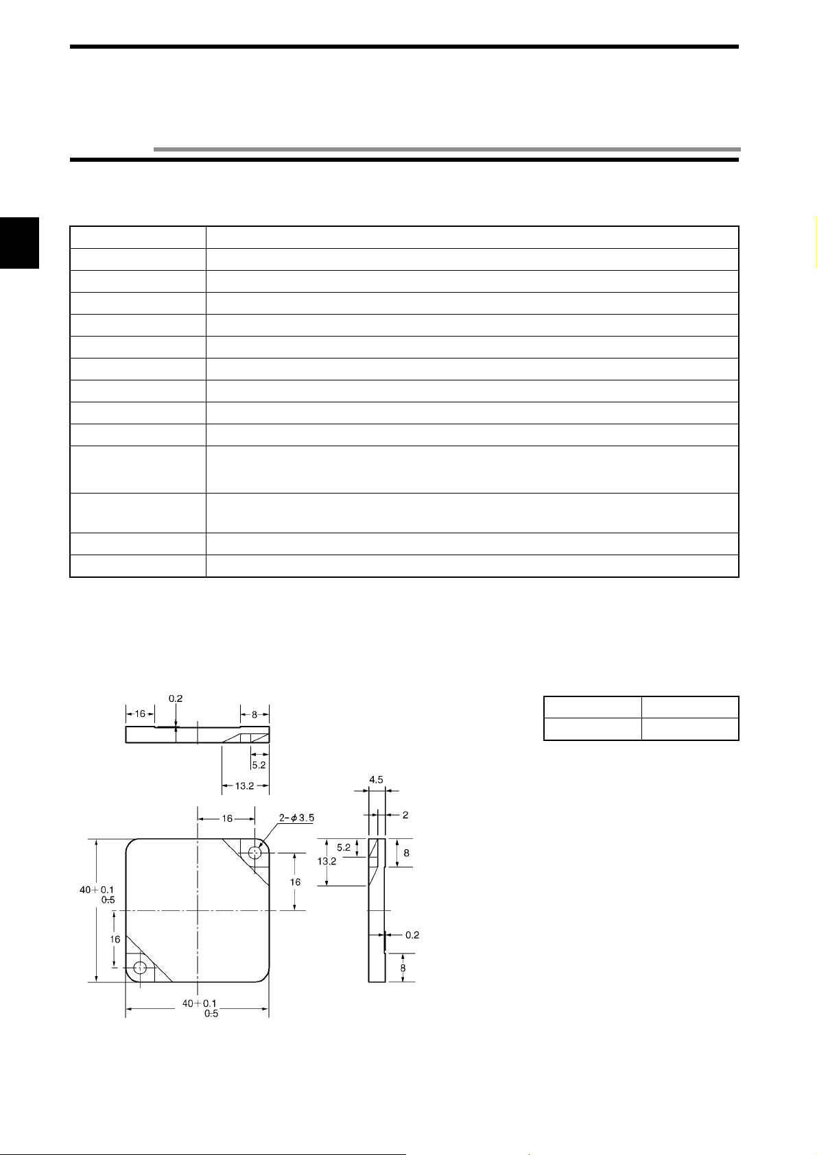
2-3-2 Outside Dimension
• Model V670-D13F03
Case material ABS resin
Filler resin Epoxy resin
(Unit: mm)
2-8
Page 21

2-3 Tag
2-3-3 Memory Map
There are a user area and ID code in memory in a tag. Memory capacity of user area is 128 bytes. You can write 1 byte of data into one
address. Memory area is divided into 4 bytes of pages and every page has its own address like 0000h to 0003h, 0004h to 0007, etc.
♦
Memory Map
Page User Address
$0000
1
.
.
.
.
* When a protect f unct ion is used, th e a dd resses 00 00h t o 00 03 h are u sed as pr ote ct ad dres s i nfo rmati on and cann ot be used as a user
area. For details, refer to "4-6 W rite Protec tio n Fun c tio n" .
♦
ID Code
This is a 4-byte area where tag identificatio n num ber (inherent tag number) is written. The ID code is writt en at shipment from a factory and it cannot be modified. The ID code can be read by an ID read command.
$0002
$0003
$0004
$007F
When a protect function is used When a protect function is not used
User Area
.
.
.
.
User Area
Specified address in a protect area$0001
User Area
2-9
Page 22

2-4 Cable
2-4-1 Specifications
Item
Insulation resistance
Model
50 MΩ or more between a terminal and
Model V700-P10 Model V670-A4!
20 MΩ or more between a terminal and
sheathing (at 250 VDC mega).
sheathing (at 1000 VDC mega).
!
!!
Withstand voltage 250 VAC, 1 minute. 1000 VAC, 1 minute.
Maximum operating
70°C70°C
temperature
Remarks Connector without waterproof specification. Connector without waterproof specification.
2-4-2 Outside Dimension
• Model V700-P10 (Programming console connecting cable)
Item Model V700-P10
Length Approximately 2 m
Weight Approximately 110 g
Connector (at a programming console side)
Connector (at a controller)
(Unit: mm)
• Model V670-A4!!!! (Antenna extension cable)
Item
Model
Length Approximately 3 m
Weight
Model V670-A40 Model V670-A41 Model V670-A42 Model V670-A43
Approximately 10 m Approximately 18 m Approximately 28 m
Approximately 140 g Approxi ma te ly 41 0 g Approxim ate ly 71 0 g
Approximatel y 1100 g
L1 3000 mm 10000 mm 18000 mm 28000 mm
Connector
Connection label
Coaxial cable 5 mm in diameter
Connector
(Unit: mm)
2-10
Page 23

2-5 Communication Range Specifications
Communication range varies depending on the installation conditions and environment conditions. Check the conditions mentioned in
this manual carefully.
♦ Maximum communication range (Actual value)
Antenna / Controller ID Tag Communication Range (Unit: mm)
Model V670-CD1D
+ Model V670-H11
Measurement conditions:
Model V670-D13F03 5 to 23 m
(Area width 20 mm or more if the range between a tag
and antenna is 5 to 20 mm.)
Antenna
Communication
range
Nonmetal
Tag
Nonmetal
2-5-1 Communication Area (Reference)
The communication area for model V67 0-H1 1 is shown be low . The communica tion area varies depe nding on the installation cond itions
and grounding environment.
The operation area formed on a plane, which is on an antenna center line and vertical to the antenna, is shown below.
Communication area characteristic
Nonmetal
Tag
Unit: mm
Antenna
Nonmetal
2-11
Page 24

2-5 Communication Rang e Specifications
2-5-2 Operation Time (Reference)
There are TAT (Turn Around Time) and communication time in the operat ion time.
Command
Communication time
Response
TAT means the total processing time required to operate V670 from the viewpoint of a host device. The communication time means a
time required for the communication between an antenna and tag, excluding host communication.
♦ Communication time
Time required for the communication between an antenna and ID tag. The time varies depending on data amount to be read and written.
The communication time can be calculated from the charts and formulas below.
• Read
Communication time (ms)
•
Write
Communication time (ms)
Number of processed bytes (Bytes)
• Write (with verificati on)
Communication time (ms)
Number of processed bytes (Bytes)
Number of processed bytes (Bytes)
Command Bytes Communication
time (ms)
Read 1 to 64 bytes
65 to 128 bytes
0.07 x N + 4.22
0.07 x N + 5.64
ID Read 4 bytes 1.59
Write 1 to 128 bytes 0.07 x N + 4.72
Write
(with verification)
1 to 64 bytes
65 to 128 bytes
0.14 x N + 6.45
0.14 x N + 7.79
N: Number of bytes to be processed
2-12
Page 25

2-5 Communication Range Specifications
In the communication with a tag, any data is read and written at every 4 bytes. Therefore, to minimize the communication time, specify
the address and the number of bytes suitably so that the address for writing can be a multiple of 4.
Example: If 4 bytes of data is written from the address 0001h, change the addr ess to 0000h.
If you cannot change as stated above due to the structure of change syst em, add the following time to the commu nication time.
When a protect function is used +2.9 ms
When a start address is not a multipl e of 4 +2.9 ms
When an end address (start address + the number of addresses) is not a multiple of 4 +2.9 ms
♦ TAT
Time from the start of command transmission by a host device to the end of receiving of response to the host device. It can be calculated
from the communication time and the number of characters of command/response. The formula is as follows:
TAT = command transfer time + communication time + response transmission time
Transmission time = x number of characters (second)
* The number of bits per character and baud rate vary depending on the communication conditions (baud rate, data length, parity and
stop bit).
Assuming that the number of cha r acters of command is A, the number of characters of response is B, the baud rate is 90 00 bps, data
length is 7 bits, parity is even and stop bit is 2 bits, the following formula can be obtained:
11 x (A + B)
TAT =
9600
Bits per character (bit)
Baud rate (bps)
+ communication time (second)
Correct Usage
The formula above calculates the time when processing (transmission of command) starts if the ID tag is within an area
of communication with an antenna. The time varies depending on a communication mode and ID tag status.
2-13
Page 26

2-5 Communication Rang e Specifications
2-5-3 Traffic and Passing Speed (Reference)
•
Read
Passing speed (m/min)
Number of processed bytes (Byte)
•
Write (without verification)
Passing speed (m/min)
Number of processed bytes (Byte)
Distance
Distance
Measurement Conditions:
Nonmetal
Tag
Passing speed (m/min)
Distance (mm)
Antenna
Nonmetal
• Write (with verificati on)
Passing speed (m/min)
Number of processed bytes (Byte)
• ID Read
Distance Passing speed
10 mm 750 m/min
15 mm 710 m/min
20 mm 600 m/min
Distance
2-14
Page 27

Chapter 3 Setting and Installation
3-1 Controller
3-1-1 Switch Setting
To set the switches, open a cover at the left upper part of the unit.
3-1-1-1 How to Open Cover
To open the cove r, insert a screwdriver , whic h comes with the controller, into a notch at the left end of the cover.
When the cover opens, you can see the two node number setup switches ( SW1 and SW2), two dip switches (SW3 and SW4) and connecting port for programming console.
Node number setup switch
Dip switch
Connecting port for programming
console
3-1
Page 28

3-1 Controller
3-1-1-2 How to Set
Set the switch using the screwdriver which comes with the controller as shown below.
• Setting a node number
Turn clockwise or counterclockwise.
• Setting a dip switch
Set to the right or left.
3-1-1-3 Setting List
Set the switches according to the list below. (The switches are set to a default value at shipment from a factory.)
Name Function Default Value
SW1 1: Node number setup switch used in N protocol. 00
SW2
(Left)
SW3-1
SW3-2 Switch to set an operation mode at startup.
SW3-3 Switch to enable or disable verification at writing. Disabling verification
SW3-4 Switch to set a protocol (1:1 / 1:N). 1:1 protocol
SW3-5 Set to OFF. OFF
SW3-6
SW3-7
SW3-8
SW4-1 Switch to set a communication speed of RS-232C. 9600 bps
SW4-2
SW4-3 Switch to set data length of RS-232C. 7 bits
SW4-4 Switch to set parity of RS-2 32C. Even parity
SW4-5
SW4-6 Switch to set stop bit of RS-232C. 2 bits
SW4-7 Set to OFF. OFF
SW4-8
Switch to change a function of input terminal (RST/IN).
Reset input
Command execution mode
3-2
(Right)
Page 29

3-1 Controller
3-1-1-4 Setting Node Number Setup Switch
♦
Node number
To connect several controllers to one host device using a link adapter etc., the host device needs to identify each of those controllers.
The number to identify them is referred to as node number. A unique node number must be assigned to every controller.
The command and response of 1:N protocol have the node number. So, unless the node number is assi gned appropriately, any communication cannot be made.
Setting node number
♦
Set the node number with the two node number setup switch. SW1 (left) is for an upper order and SW2 (right) for a lower order. Available number range is from 00 to 31 as shown below.
SW1 SW2
Upper
order
000
011
022
033
044
055
066
077
088
099
1010
1011
:::
2929
3030
3131
3 2 Disabled
3 3 Disabled
:::
9 9 Disabled
Lower
order
Node Number
Example of setting:
Node No. 0
Node No. 17
The factory default setting of the node number is 00.
Correct Usage
Never assign the numbers 32 to 99 to the node number setup switch.
3-3
Page 30

3-1 Controller
3-1-1-5 Setting a Dip Switch
♦
SW3
SW3-1: Input function change
SW3-1 Description
ON Functions as trigger input.
OFF Functions as reset input.
SW3-2: Operation mode
SW3-2 Description
ON Starts in the Self-Execution mode when the power supply turns ON.
OFF Starts in the Command E xecution mode when the power supply turns ON.
SW3-3: Verification at writing
SW3-3 Description
ON Enables verification at a write command.
OFF Disabl es verification at a write command.
SW3-4: Protocol designation
SW3-4 Description
ON Uses the 1:N protocol.
OFF Uses the 1:1 protocol.
Correct Usage
Set SW3-5, SW3-6, SW3-7 and SW3-8 to OFF always. Otherwise, any operation cannot be guaranteed.
3-4
Page 31

♦
SW4
SW4-1/4-2: Communication speed setting
SW4-2 SW4-1 Description
ON ON 115200 bps
OFF 38400 bps
OFF ON 19200 bps
OFF 9600 bps
SW4-3: Data length setting
SW4-3 Description
ON 8 bits
OFF 7 bits
3-1 Controller
SW4-4/4-5: Parity bit setting
SW4-5 SW4-4 Description
ON ON Even parity
OFF No parity
OFF ON Odd pari ty
OFF Even parity
SW4-6: Stop bit setting
SW4-6 Description
ON 1 bit
OFF 2 bits
Correct Usage
Set SW4-7 and SW4-8 to OFF always. Otherwise, any operation cannot be guaranteed.
3-5
Page 32

3-1 Controller
3-1-2 Instal lation Site
The controller model V670-CD1D has high r e liability as durab le control device under any environmental conditions. To increase the
system reliability and to fulfill the functions completely, install the controller according to the instructions below.
♦
Installation site
Do not install the controller at any place below:
• Place where the amb ient temperat ure is out of th e range between 0 and +55°C, where the temperature fluct uates considerably and
where moisture condensat io n occurs.
• Place where the relative humidity is out of t he range between 35 and 85%RH.
• Place where there is corrosive gas, fl ammable gas, dust, salt or iron powde r.
• Place affected by vibr ation or impact.
• Place exposed to the direct sunlight.
• Place splashed with water, oil or chemicals
Assembly in panel
♦
The ambient operating temperature of controller is between 0 and +55°C. The following conditions must be met.
• Provide sufficient space for ventilation.
• Do not install the controller near by any heating sources (heater, transformer and large-sized resistance).
• If the ambient temperature rises to 55°C or more, install a ventilating fan or air conditioner to keep the temperature at 55°C or less.
• If you wire a power line (for high current to drive a motor) near the controller, test it fully to reduce the influence of noise and wire it
according to the wiring conditio ns with care.
Note
When you install the controller, be sure to follow the instructions above and test it fully.
3-6
Page 33

3-1 Controller
3-1-3 How to Install
The controller can be installed in a panel with screws or on a DIN rail.
♦
Installation in a panel
If you install the controller in a panel, be sure to use spring washers, fla t washers and M4 screws. (Tightening torque: 1.2 N•m or less)
Do not use any organic solvent such as lock paint to fix screws. Otherwise, the case may crack.
♦
Installation on a DIN rail
DIN Rail
Recommendable DIN rail
Model PFP-100N2 (Rail
length 1 m)
(OMRON)
(Unit: mm)
• When you install the controller on the DIN rail, hook the
controller ov er the A an d push th e control ler in the direc tion B.
• When you remove the controller from the DIN rail, pull
the hook downward and remove the controller pushing
slightly upward.
End Plate
Support Rail
Model PFP-100N2
Hook
(Unit: mm)
End Plate
Model PFP-M
3-7
Page 34

3-1 Controller
3-1-4 How to Connect Antenna
You can connect one antenna to the controller. The antenna can be extended up to 30 m by using the extension cable model V670-A4!
(unbundled). Only one extension cable can be used.
♦
How to connect and disconnect a connector
• How to connect
Lock
• How to disconnect
Lock
(1) Hold the ca ble lock of connector and fit a lug of the co n-
troller in a groove in the conne ctor lock.
(2)Push the connector straight tightly.
(3)Turn the connector lock clockwise.
(1)Turn the connector lock counterclockwise.
(2)Hold the lock and pull out it straight.
Correct Usage
Do not pull the cable forcibly. Otherwise, the cable may be broken or damaged. When you connect or disconnect the
connector, be sure to turn off the power supply. Otherwise, a trouble may occur.
3-8
Page 35

3-1 Controller
3-1-5 How to Connect Extension Cable and How to Extend Antenna
The antenna can be extended by using the extension cable type V670-A4! (unbundled). The ext e nsion cables up to 28 m in le ngth are
available. When you use the extension cable, to prevent the devices being broken due to static electricity, follow the instructions below:
♦
Procedure to connect extension cable
Connect the antenna and exten sion cable with a connector accessory (accessory: WTN-B-384). Cover a metal part of connect or joint
with a sheath (Sumitomo Electri c Industries: SumiTube A 20 mm in diameter) as shown below.
Approximately
15 mm
Approximately
100 mm
Approximately
15 mm
Heat the sheath (120°C is recommendable) using a dr ie r etc . to s hrink it.
* The cable and connector may be deformed if the sheath is heated for a long time. Heat the sheath quickly.
Procedure to disconnect extension cable
♦
Remove the tube using a nipper etc. first and then remove the extension cable. If a new tube is required, use the heat shrinkable tube
(SumiTube A 20 mm in diameter) of Sumitomo Electric Industries which should be cut down to 10 cm.
3-1-6 How to Wire
Wire as shown in this figure.
3-9
Page 36

3-1 Controller
3-1-6-1 Wiring Power Supply and Grounding Cable
(Example of Wiring)
+24 VDC
Grounding of Class D
M3 self-up screws are used for the power supply and ground terminal. For a crimp terminal, use any of terminals below. Tightening
torque should be appr oximately 0.6 N•m.
♦
Applicable crimp terminal
Manufacturer Model Applicable Wire Type
Japan Solderless
Terminal
Japan Solderless
Terminal
♦
Recommendable DC power supply (small-sized) (OMRON)
Model Output Capacity Inpu t Voltage
S82K-03024 24 VDC 1.3 A 100/200 VAC
S82J-0224 24 VDC 1.1 A 100 VAC
* Rated power consumption of the controller is 24VDC and 0.2 A (7 W). Decide the capacity taking into consideration inrush current
(approximatel y 5 A).
1.25-N3A AWG24 to
AWG16
1.25-Y3A
Fork
(For M3)
3-1-6-2 Wiring Reset Signal
3-10
24 VDC
Reset Input
Page 37

3-1 Controller
• Crimp terminal for terminal
M3 self-up screws are used for the terminal.
For a crimp terminal, use the terminal below.
(For M3)
Tightening torque should be approximately 0.6 N•m.
Correct Usage
Take care that the input vol tag e does not exceed the a maximum impres s ed vo lta ge (26 .4 V). Othe rwis e, a trouble may
occur in devices.
3-1-6-3 Wiring Output Signal
DC Power
Supply
• Crimp terminal for terminal
M3 self-up screws are used for the terminal.
For a crimp terminal, use the terminal below.
(For M3)
Relay
External
I/O Unit
Tightening torque should be approximately 0.6 N•m.
3-11
Page 38

3-1 Controller
3-1-7 Connecting RS-232C Interface
Signal Name Code Signal Direction Pin No.
Input Output
Ground for maintenance GR — — Shield
Ground for maintenance or common return SG — — 5
Send data SD — 3
Receive data RD — 2
Request to send RS — 7
Clear to send CS — 8
Controller Pin Layout
(TOP VIEW)
Note 1. To prevent an operation error, ground the shielded wire either at the controller side or the computer side mentioned above. (The
figure above shows an example of groundi ng the shielded wire at the ID controller side.)
Note 2. Short-circuit pin No. 7 (RS) and pin No. 8 (CS) at the inside of the connector.
Connecting to a host device of IBM PC compatible machine, 9-pin
View of fitting face of cable connector
at the controller side
Controller
Controller Connecting Device
9-Pin, male
9-Pin, male
Shield
Shield
Connector with a cable
Connecting Device
Conector with a cable
View of fitting face of cable connector
at the host device side
IBM PC Compatible Machine
IBM P C Com patible Machine
9-Pin, female
9-Pin, f emale
3-12
(Shielded wire)
(Shielded wire)
Page 39

Connecting to a host device of NEC PC-9801 compatible machine, 25-pin
3-1 Controller
View of fitting face of cable connector
at the controller side
Controller
9-Pin, male
Shield
Connector with a cable
Connecting Device
(Shielded wire)
View of fitting face of cable connector
Connecting to the OMRON programmable controller (PLC) (C200H)
View of fitting face of cable connector
at the controller side
View of fitting face of cable connector
at the host device side
13
NEC PC-9801 Compatible Machine
25-Pin, male
at the host device side
Controller
9-Pin, male
Shield
Connecting Device
Connector with a cable
(Shielded wire)
Type C200H-ASC02
25-Pin, male
3-13
Page 40

3-1 Controller
♦
Assembling and connecting a connector for communication
Use our connector for communication , which comes with the controller. Prepare a connecting cable an d connector for a host computer
by yourself. Our connector which comes with the controller is based on the countermeasures against EMI.
(Instead of our connector which comes with the controller, you may use any other commercial connector. Refer to "Appendix 2 Order
Format List".)
To the ID controller
Plug
Model XM2A-0901
(which comes with the
controller)
(OMRON)
* 1. One set of connectors (based on the countermeasures against EMI) comes with the ID controller.
* 2. You may use any other cable if the cable specifications are the same as ours. (The outer diameter is 7 mm.)
♦
How to assemble a connector
Hood
Model XM2S-0911 *1
(which comes with the controller)
(OMRON)
Connecting cable
• Recommendable cable
CO-MA-VV-SB 5PX28AWG *2
(Hitachi Cable)
(1)Terminate the cable properly.
• Fit the cable bush in the cable in advance.
• Ravel the shield braid, turn back it and cover the
cable bush with the shield braid. The length of the
shield braid covering the cable bush should be 10
mm.
• Wind the shield tape on the shield braid.
Core
Shield braid
Shield tape
Cable bush
To the host computer
(2) Solder the core and plug pin.
Plug
Crossover
Cable bush
Aluminum tape
(Unit: mm)
Pin No. Code Name
Shield GR Ground
5 SG Ground for signal
3 SD Send data
2 RD Receive data
7 (Note) RS Request to send
8 (Note) CS Clear to send
Note. Short-circuit No. 7 (RS) and No. 8 (CS) pins with crossover.
3-14
Page 41

(3)Set the plug in the housing A2 of the h ood and fix the aluminum ta pe with a clamp.
Lock screw (2-M2.6)
Housing A2
3-1 Controller
Cable clamp
Housing B2
(4)Set the two connector lock screws and put the housing B2 there to complete the connector.
♦
How to connect and disconnect a connector
• When you connect the connector, be sure to hold the connector and insert it completely. When you have inserted the connector,
tighten the two lock screws with the Phillips screwdriver.
• When you disconnec t the conn ector, loosen the t wo lock scr ews and pull out the lug of conn ector hoo d strai ght. If it i s hard to pull
out the connector, hold the controller tightly and pull out it.
Phillips screwdriver
Lock screw
Correct Usage
Example of grounding a shielded wire at the controller side:
ID controller
Host computer
• To prevent an operation erro r, ground the shielded wire
either at the controller side or the host computer side.
(This figur e sh o w s an example of grou nding it at the controller side.)
• Short-circuit the RS pin and CS pin inside the connector.
3-15
Page 42

3-2 Antenna
3-2-1 Instal lation Site
♦
Installation site
Do not install the antenna at any place below:
• Place where the ambien t tempera tur e is ou t of the rang e be tween -1 0 an d +70°C, wh ere the t empera ture fluc tuat es cons iderab ly an d
where moisture condensat io n occurs.
• Place where the re lative humidity i s out of the range between 35 and 85%RH.
• Place where there is corrosive gas, fl ammable gas, dust, salt or iron powde r.
• Place affected by vibr ation or impact.
• Place splashed with water, oil or chemicals
Note
When you install the antenna, be sure to follow the instructions above and test it fully.
3-2-2 How to Install
• Installation on a surface
M4 screw
(Tightening torque: 1.2 N•m or less)
•
Installation on the back
Insert a nut which comes with the antenna into the section A.
M4 screw
(Tightening torque: 1.2 N•m or less)
(Unit: mm)
M4 nut
(Unit: mm)
3-16
Page 43

3-3 Tag
3-3-1 Installation Site
Do not install the tag at any place below:
• Place where there is corrosive gas, flammabl e gas or iron powder.
• Place where the ambi ent tempe rature i s o ut of th e rang e bet ween -10 a nd +70°C, where the tempe rature fl uct uates con sidera bly and
where moisture condensation occurs.
• In a microwave oven.
3-3-2 How to Install
Install the tag according to the following instructions:
• Neither shave, drill nor machine the tag.
• Do not apply any excessi ve force to the tag.
• Neither contact the tag and any metal with each oth er nor install the tag near an y metal.
* When the tag is used in both high temperature and low temperature, the tag may bend. However, the function is not affected.
Type V670-D13F03
♦
•
Tag installation direction
Antenna
Install this tag so that the tag surface ca n be in parallel with the antenna.
• Example of installation
Install the tag with the screws .
M3 screw (Tightening torque: 0.6 N•m or less)
(Unit: mm)
3-17
Page 44

Chapter 4 Functions
4-1 Communication Designation Function
Depending on an operation sequence, you can specify vario us communications through the communication command for communication with a tag. The following seven communicatio n de sig natio ns are avai labl e.
Code Name Description
ST Single command Trig ger When the command is received, the c om mu nic at ion w ith the ta g is e xe cut ed and
the response is returned.
SA Single Auto command After the command is received, the communication is executed when a tag has
been detected in a communication area and the response is returned.
SI Single Input trigger After the command is receive d, the comm unication w ith the tag is executed at the
leading edge timing of external input (TRG) and the response is returned.
RA Repeat Auto command "SA" designation is repeated. The communication with the same tag, which
exists continuously, is executed only one time.
RI Repeat Input trigger "SI" designation is repeated.
PA Poling Auto command "SA" designation is executed and the response is returned by the polling query
(PC) command.
PI Poling Input trigger "SI" designation is executed and the response is returned by the polling query
(PC) command.
Those seven communication designations are classified into three groups; a command trigger system which starts the communication by
sending a command, auto s yst em which detects a tag automatically and executes the communi cation, and input trigger syst em which
start the communication by external input.
According to this classification, the operation of every communication designation is described below.
4-1-1 Designation of Command Trigger System Communication (ST)
In the command trigger system communication designation, the communication with a tag is executed by sending a command and the
controller command processing is ended by terminating th e communication. If the tag is not in the communication area when the command is sent, an error (error code: 72) is returned to indicate that there is no tag in the communication area. Therefore, you must check
the tag in the communication area with a sensor etc. and return a command.
The communication with tag in the
communication area is executed when
a command from a host is received.
So, if the tag is not in the communication area, the response is returned to
indicate that there is no tag in the communication area.
* Responds whether there is a tag or not.
ST designation:
Antenna
Host → Controller
Tag
ST mode command
Host ← Controller
Controller ↔ Tag
(Tag action)
Communication
Tag
Response *
End of process
4-1
Page 45

4-1 Communication Designation Function
4-1-2 Designation of Automatic System Communication (SA/RA/PA)
In the auto system communication designation, a tag is detected automatically. So, unlike the command trigger system, you do not need to check the tag.
When the tag enters the communication area, the communication starts.
Tag
Antenna
SA designation:
For the single designation (SA), the controller command processing is ended by terminating the communication.
Host → Controller
Host ← Controller
Controller ↔ Tag
(Tag action)
SA mode command
Communication
Tag
Response
End of process
RA designation:
For the repeat designation (RA), the system waits until the next tag has come even after the communication is terminated. If the tag
once executes the communi cation, the tag does not execute the communication un til it has moved out of the communication area.
Repeat processing is ended by a command process abort command (AA).
Host → Controller
Host ← Controller
Controller ↔ Tag
(Tag action)
RA mode command
Waiting for a tag
Communication
A
Response
Waiting for a new tag
Tag A
Response
B
Waiting for a new tag
Communication
Communication
Tag B Tag B
Response
C
AA command
Response
End of
process
PA designation:
In the PA designation, similarly with RA, processing is repeated until the processing is terminated by a command process abort command (AA). However, no response is made after the communi catio n with one tag is ended. Response is returned by a pollin g qu ery
(PC) command instead. Use this designation when several controllers are connected to a host device through RS-485, etc. (Commercial
232C/485 converter is required.)
Host → Controller
Host ← Controller
Controller ↔ Tag
(Tag action)
4-2
PA designation command
Response
(Acceptance)
PC command
Waiting for a tag
Response
(No communication)
PC command
Commu nication
Tag
Response
(Result of communication)
End of process
Page 46

4-1 Communication Designation Function
4-1-3 Designation of External Trigger System Communication (SI/RI/PI)
In the external trigger system communication designation, the communication is started at a leading edge of an external input signal.
The communication is directly controlled by output of a sensor which detects a tag in the communication area. So, the communication
can be executed even in a fast line without fail.
To the external input of ID controller
The system waits for a leading edg e o f an
input signal when a command has been
issued by a host. (An sensor is one of
examples.) The communication is exe-
Tag
Antenna
cuted to the tag in the communication
area at the leading edge of the input signal. If the tag is not in the communication
area, an error occurs to indicate that there
is no tag in the communication area.
SI designation:
In the single designation (SI), the controller command processing is ended by terminating the communication.
Host → Controller
Host ← Controller
Controller ↔ Tag
External input
SI mode command
Waiting for input
* Responds whether there is a tag or not.
Response*
Communication
End of process
RI designation:
In the repeat designation (RI), the system waits for a leading edge of the next input signal even after the communication is ended. The
communication is executed to the tag whenever the leading edge of input signal is detected. Repeat processing is ended by a command
process abort command (AA).
Host → Controller
Host ← Controller
Controller ↔ Tag
External input
SI designation command
Waiting for
input
* Responds whether there is a tag or not.
Response*
Communication
Waiting for input
Communication
Response*
AA command
Response*
(Terminated)
End of
process
4-3
Page 47

4-1 Communication Designation Function
In the polling designation (PI), similarly with RI, processing is repeated until the processing is terminated by a command process abort
command (AA). However, no response is made after the communication with one tag is ended. Response is returned by a polling query
(PC) command inst ead . Use this desi gna tion w hen seve ral contro ller s ar e co nnec ted to a ho st de vi ce th rough RS- 485 etc. (Co mme rcial
232C/485 converter is required.)
PI designation:
Host → Controller
Host ← Controller
Controller ↔ Tag
External input
PI designation command
Response*
(Acceptance)
PC command
Waiting for input
Response*
(No communicatio n)
PC command
Communication
Response*
(Result of communication)
End of proces s
Correct Usage
To use the communication designation of SI, RI and PI, turn ON (trigger input) the dip switch 3-1.
4-4
Page 48

4-2 Tag Designation Function
When reading data or writing fixed data, you can use "Repeat Auto" designation or "Repeat Trigger" designation. However, if you write
different data per tag or if you use several commands (e.g., read → judge → write), you cannot us e this function.
To enable this process, you can use the Tag Designation function. By using this function, regard less of timing, you can only send the
commands consecutively to communication with an objective tag without fail. Moreover, a sensor for tag detection is not required. So,
the system configuration can be simplified.
Code Description
“sa” When a tag enters the communication area, the communication to the tag is executed. The communication is
made to any tag other than the tag to which the communication has been executed immediately before. If the
same tag exists continuously, the system waits until any other tag enters the communication area.
“st”
<Example of process sequence>
When you execute a command 1 and command 2 to the tags (A, B, ...) moving continuously, you can use the following sequence.
When a command has bee n re ce ive d, th e co mm u nic atio n is executed to the tag in the commu nic atio n ar e a. Th e com m u nication is made to any tag other than the tag to which the communication has been executed immediately before. Even if
any different tag is in the communication area, an error occurs to indicate that there is no tag in the communication area.
Host
↓
Controller
Command 1
(sa
designation)
Command 2
(st
designation)
Command 1
(sa
designation)
Command 2
(st
designation)
Host
↑
Controller
Controller
↓↑
Tag
Waiting
for a new
tag
Communication
1A
Response
Previous tag
only
Communication
2A
Response
Waiting
for a new
tag
Communication
1B
Response
Previous tag
only
Communication
2B
Tag
in communication
area
Tag A
Tag B
When you write differ ent data into the tags (A , B, ...) moving continuously, you can use the following sequ ence.
Host
↓
Controller
Host
↑
Controller
Controller
↓↑
Tag
Tag
in communication
area
Command 1
(sa
designation)
Waiting
for a ne w
tag
Communication
A
Response
Command 2
(st
designation)
Tag A
Waiting for a new tag
Communication
B
Response
Command 2
(sa
designation)
Tag B
Waiting for a new tag
Response
Command 1
(sa
designation)
4-5
Page 49

4-3 Operation Mode
There are two operation modes, i.e., Command Execution mode and Self-Execution mode. Through the dip switch 3-2, you can specify
one mode of them to be started at the power ON. Also, you can change the mode by a mode change command (MO) from a host device.
Power ON
Command Execution
mode
Mode change command (MO)
Self-Execution mode
(1)Command Execution mode
The communication is exe cuted by an in struction (command) from a host dev ice. In this mode, you can use all the command. All,
you can read/control the ext ernal I/O terminals (IN, OUT1 and OUT2) by a command from a host device.
(2)Self-Execution mode
The communication to a tag is executed automatically according to the o perating conditions registered in the controller, the communication result can be judged (jud g men t c on dit ions ), a nd th e self-co m ple tio n op eration, to which is output to the two exte rna l outputs
(OUT1 and OUT2) or to the RS-232C port (result output), can be performed. The ID system does not need to be controlled from a
host device. So, a simplified system can be built up very quickly. The following operating conditions can be registered.
Item Description
Execution process A communication command only can be used. An available communication mode is RA or RI
only.
Judgment conditions
One of the conditions below can be specified per output.
1) Judges the communication result and generates output.
2) Compares response data and set data with each other and generates output.
Result output When a preset judgment condition has been met, the three outputs below can be specified. The
judgment condition can be specified per output.
1) Outputs to OUT1. Output time can be specified.
2) Outputs to OUT2. Output time can be specified.
3) Responds to RS-232C.
The preset operating conditions are stored in nonvolatile memory in the controller. So, you do not need to set them at every power on.
4-6
Page 50

4-3 Operation Mode
<Example of usage >
When data is read out of the ta g into wh ic h de stin ation in form atio n ha s b een writt en , t he a pplic a bl e de stin at ion o nl y i s de tec ted and the
pulse is output, and reading could not be done due to any trouble, an error pulse is outp ut as shown below.
Error output
Fast movement
Setting and operation flow
•
Antenna
Tag
Coincidence
output
Trigger input
(Synchronization sensor)
Setting of operating conditions
Item Description
Execution process Communication command: RD
Communication mode: RI
OUT1 Outputs OUT1 in tms at data
matched.
OUT2 Outputs OUT2 at abnormal end.
RS-232C Nil
Error output
Coincidence
output
Trigger input
(Synchronization sensor)
Power ON
TRIG input
Data read (E)
Correct end
Trigger input (IN)
Coincidence output(OUT1)
Abnormal output (OUT2)
Communication process
Data matched
Data matched(D)
Coincidence
output pulse
Communication process
Data unmatched
Communication process
Data matched
Abnormal output
pulse
4-7
Page 51

4-4 Operation Parameter Setting
In the controller, you can specify the operation parameters (Communication Restriction Time, Character Interval Monitoring Time and
Response Ready Time) according to your system to optimize the performance and reliability.
Usually , you may use the d efault valu es. Howeve r , th is setting a llows you to op timize your system. Those param eters are store d in nonvolatile memory in the controller. So, the parameters are not erased even if the power supply turns off.
4-4-1 Communication Restriction Time
In the communication to a tag, if a response cannot be made correctly due to any trouble at the communication after tag detection,
"Retry" is executed to sen d t he same command again.
By specifying the communication restric tion tim e , retry is rep eat ed un til th e specifie d time has pa ssed af ter the comma nd pro ce ss starts.
Controller → Tag
Controller ← Tag
Host ← Controller
External input
Send
Send
Retry
Communication restriction time
Send
Retry
Response
Error 72
In the external trigger system command, command process starts when the command process starts. In the auto system command, command process starts when the tag has been detected.
Setting Range
10 to 990 ms. A default value is 0.
* If the default value is set, "retry" is repeated 9 times.
4-4-2 Character Interval Monitoring Time
In the cont roller, a c om m an d is re cognized by receiving a termination c ode of command string sent from a h os t device. Howeve r, if the
entire command string cannot b e re ceived completely due to any trouble, receiving is monitored for a specified time after the last character is received. Then, a format error (14) is returned.
Host → Controller
Host ← Controller
Setting Range
0 to 9999 ms.
* The default value i s 100 ms.
4-8
External input
If there is no data any more
Termination
code
Character interval monitoring time
Response
Error 14
Page 52

4-4 Operation Parameter Setting
4-4-3 Response Ready Time
When several controllers are conne cted to a host device through RS-485 etc. (commercial 232C/485 converter is requir ed), RS-485
switches into receiving after data string is sent. Switching time varies depending on a converter. So, if a response from the controller is
fast, the communication cannot be executed correctly.
By specifying the Response Ready time, the response start time can be changed.
*Actual time from the transmission of command to the start of response is internal process time (a minimum time is 0 ms) of the con-
troller + Response Ready time (specified time).
Host → Controller
Host ← Controller
External input
Setting Range
0 to 9999 ms.
* The default val ue is 0 ms.
Command
Internal process time
Response
Response Ready time
Correct Usage
For how to use the operation parameter setting (SP) command, refer to the description of "5-8-6 Parameter Setting
(SP)".
4-9
Page 53

4-5 Memory Check Function
Add
By adding a check code to a data in a ta g, you can detect a data error arisen from memo ry rewrite life or unintentional factor. A CRC
code of generating polynomial X
16
+ X12 + X5 + 1 is used as the check code.
For memory check, a memory check command (MC) to write a check code and a memory calculation command (MK) to verify the
check code are used.
In a check block specified by th e first address and the number of
ress
bytes, an area excluding the last 2 bytes of the block is a target area
to be calculated and the l ast 2 bytes are a check code area.
When a command to write the check code is sent, the CRC code of
data in the target area for calculation is calculated and it is written
into the check code area. When a data ve rification command is
First address in this
area →
sent, the CRC code of data in the target area for calculation is calculated and it is compar ed with data of the check code area. If
those data match, "0" is returned. This shows that the data is correct in a response status flag. If those data do not mat ch, "1" is
returned as warning.
(High order
digit)
(Low order
digit)
Target area for check code
calculation
(Number of check block
bytes: 2)
Check code area (2 bytes)
<How to use>
Calculate/write the check code with the memory check command (MC) after writing a data and verify the check code with the memory
calculation command (MK) before reading it. Beforehand, you can detect data corruption in the tag which is not accessed.
Writing stage
Reading stage
Data writing
Check code calculation
Check code verification
Data reading
4-10
Page 54

4-6 Write Protect Function
The Write Protect Function prevents a fixed data, such as pallet information or product information stored in memory in a tag, being
erased by careless writing.
By setting protect information in the tag, Write Protect can be enabled in any area (a maximum of two areas) of a specified address. If
you try to write anything into a write-protected page, a Protect error occurs.
The protect are a information is set by using a part (address $0000 to 0003) of u s er data area.
To enable the Write Protect, write th e pr otect area information into a speci fied address and specify "Protect Setting" with process designation parameter using a tag fun ction set tin g com mand (TF). Similarly, to d isable th e Write Protect, specify "Disable" with the process
designation param eter.
Relation between Protect information and Protect area
♦
User Address Description Example of data
$0000 Start address of Write Protect area 1 05h
$0001 End address of Write Protect area 1 10h
$0002 Start address of Write Protect area 2 70h
$0003 End address of Write Protect area 2 75h
$0004
$0005
$0010
$0011
$006F
$0070
$0075
$0076
.
.
.
.
.
User Area
Write Protect area 1
Write Protect area 2.
$007F
* Available range of Protect area: 0004h to 007Fh
Correct Usage
If you use the Write Protect function, the area $0000 to 0003 cannot be used as a data area. Also, if you enables the
Write Protect function, the communication time is prolonged (approximately 3 ms).
4-11
Page 55

Chapter 5 Control From Host Device
5-1 Controller Operation Status
The V670 series RF-ID system communicates with a tag ((2)) according to the instruction of a command ((1)) sent from a connected
host device and returns the result to the host device as the response ((3)).
(2)
Tag
Communication between
the antenna and tag
Antenna
Host Device
♦
Controller operation status
•
Waiting for command
This refers to the status that the controller does not execute any command pro cess. Then, the controller can accept all the commands
except the subcommands etc. When the controller has accepted any command, the controller enters the command processing status.
•
Command processing
When the command has been accepted, the next command is ignored until the process of such accepted command is completed. However, a command process termination command and reset command can be accepted always.
Communication
(1)
Command
(3)
Response
Controller
5-1
Page 56

5-2 Command Response Format
For the format of command and respo nse communicated between a host device and controller, there are 1:1 protocol used usually and
1:N protocol used to connect several contr ollers and the configuration is described below.
The protocol is specified through the dip switch (SW3-4) of the controller.
(1) Command frame
1:1 Protocol
Command code Data
Terminator
1:N Protocol
Node No. Command code Data Terminator
Calculation range of FCS
* In the 1:N protocol, a gray part is added.
Name Description
SOH Shows the beginning of the frame with SOH ($01).
Node No. A number to identify a target controller at the 1:N connection. Specify it through a rotary switch
(SW1/2).
Command code Specifies the execution (command).
Data Specifies the parameters (address, number of bytes, etc.) for the command execution or a data to
be written.
FCS Frame check sequence. This is a code to detect an error in data string. This expresses a calcula-
tion value of horizontal parity of character string between immediately after SOH and immediately
before FCS in two ASCII characters.
Terminator Shows the end of command with two characters, "*" ($2A) and CR code ($0D).
5-2
Page 57

(2) Response frame
S
1:1 Protocol
5-2 Command Response Format
Command code Termination code
Retransmission
tatus
flag
flag
Data Terminator
n
1:N Protocol
Node No.
Command code Termination code
Calculation range of FCS
Retransmission
Status
flag
flag
Data
Terminator
* In the 1:N protocol, a gray part is added.
Name Description
Termination code Shows the command execution result.
Retransmission
Flag to show the response to retransmission. This is "1" at retransmission.
flag
Status flag Code to show the command execution status.
* For any part other than the above -mentioned, the same data as the sent comm and frame is added and returned.
♦
Retransmission flag
"0" Response after usual command process.
"1" Response returned by a request to retransmit data (RR).
♦
Status flag
"0" Communication status Shows that process has been executed correctly.
"1" Tag data status Shows that the verification result of data check command (MD) is invalid or that
overflow/underflow has occu rred in the cal cu la tion of a calcul ati on wr itin g com mand (CW).
"2" Abort status Shows that communication to a tag has been aborted after the start by an abort-
ing command (AA).
"4" Polling acceptance Shows that the polling status is enabled by accepting the communication desig-
nation "PA (pa)" or "PI".
5-3
Page 58

5-2 Command Response Format
(3) Data code designation
You can specify in a c o mmand a code to be used to tra n smit a d a ta to b e re ad or writte n b et ween a h ost de v ic e a nd ID con trol ler. ASCII
code designation and hexadecimal code designat ion are available.
• ASCII code (JIS8 unit code) designation "A"
1 Byte of data in a tag is transmitted directly as ASCII c ode or JIS8 un it cod e. Transmitted one character is equiv alent to 1 byte of data
in a tag. Character data can be read/written directly. However , d o no t use any co ntro l code [ SOH] n or [CR] in a data to be transmitted.
If [SOH] or [CR] is specified in a written data, a command error occurs.
<Example of writing>
If you specify "OMRON" as a written data in 5 bytes of memo ry be g innin g with the address 10h , the d ata is written in memory in a tag
as shown in this figure.
<Command>
Command
Commu nication
designation
ASCII
designation
Antenna
designation
First address
Number of
bytes
Written data
<Example of writing>
If you read 5 bytes of memory beginning with the address 10h,
Address
Memory in tag
the read data is "OMRON" in the data shown in this figure.
Command
Termina tion code
Retransmis-
sion flag
Status
flag
Read data
• Hexadecimal code designation "H"
1 Byte of data in a tag is converted in to tw o hex ad ec imal c h arac ter s ("0 0" t o "FF" ) an d tran smitted. Transmitted two c har ac ter is equivalent to 1 byte of data in a tag. Be sure to specify a written data with every two characters "00" to "FF" (even number). If any data of
odd number of characters is specified, a command error occurs.
<Example of writing>
If you specify "1234" as a written data in 2 bytes of memory beginning with the address 20h, the data is written in memory in a tag as
shown in this figure.
Address
<Command>
Memory in tag
Command
Commu nica tion
designation
ASCII
designation
Antenna
designation
First address
Number of
bytes
Written data
<Example of reading>
If you read 2 bytes of memory beginning with the address 20h, the read data is "1234" in the data shown in this figure.
<Response>
Command
T e rm inatio n code
Retransmis-
sion flag
Status
flag
Read data
5-4
Page 59

5-2 Command Response Format
(4) Available designation range of first address and number of bytes
Command code Available designation range of first address and number of bytes Other restriction
Read (RD) A) Available designation range of first address: 0000h to 007Fh
B) Available designation range of number of bytes: 01h to 80h
Write (WT) A) Available designation range of first address: 0000h to 007Fh
B) Available designation range of number of bytes: 01h to 80h
Computation Write
(CW)
A) Available designation range of first address: 0000h to 007Fh
B) Available designation range of computation area: 01h to 80h
Data Fill (DF) A) Available designation range of first address: 0000h to 007Fh
B) Available designation range of end address: 0000h to 007Fh
Memory Check (MD) A) Available designation range of first address: 0000h to 007Dh
B) Available designation range of number of check bytes: 03h to 80h
A command to specify the first address and the number of bytes in a command and the available designation range are shown in the
table below. If you specify any value out of the available range, a co mmand error occurs.
* If the first address is 20h and the number of bytes is 70h, a command error occurs due to "A + B = 90h".
A + B ≤ 80h*
A + B ≤ 80h*
A + B ≤ 80h*
A ≤ B
A + B ≤ 80h*
(5) Example of calculation of FCS
Exclusive-OR is executed from the node number to the end of data at every 1 byte. The result is converted into an ASCII code and
added.
Reading 16 bytes from the ad dress 000h
Node No.
Command code
Calculation range of FCS
Data
Terminator
79
Calculation result
5-5
Page 60

5-3 Command Response Flow
Depending on a type of command and the communication des ignation, receiving the command from a host device to the cont roller and
the response to the host device vary.
(1) No response
When the controller receives a reset command, the controller does not send any response, performs resetting and waits for a command.
Host Device
Controller
Reset Command
Execution of Resetting
(2) Single response
When single trigger (ST/st), single auto (SA/sa), single input trigger (SI), polling auto (PA/pa) or polling input trigger (PI) is specified
by a command to communicate with the tag, or when a command not for the communication with the tag (communication subcommand,
controller control command or host command) is specified, one response is returned to one command.
Host Device
Controller
Command
Response
(3) Several responses
When repeat auto (RA) or repeat input trigger (RI) is specified by a command to communicate with the tag, several responses are sent to
one command.
Host Device
Controller
Command
Response Response Response
Response
5-6
Page 61

5-4 Command List
The commands are classified mainly in to four categories.
(1) Communication command
Command to communicate with a tag.
(2) Communication subcommand
Subcommand used to inquir e the execution result or abort the execution when polling auto command is used.
(3) Controller control command
Command used to terminate the communication with the tag or reset th e controller.
(4) Host command
Command used for a communica tion test between the controller and host device.
Command T y pe Command Code Name Description
Communication
command
Communication
subcommand
Controller control
command
Host command TS Test Sends a data received from a host device.
RD Read Reads a data from memory in a tag.
WT Write Writes a data into memory in a tag.
CW Computation Writ e Writes the calculation result of memory data
into a tag.
DF Data Fill Fills a specified area with specified data.
MD Memory Check Specifies/verifies a check code of memory in
a tag.
TF Tag Function Designation S pecifies/cancels the Write Protect function
to a tag.
ID ID Read Reads a user ID in a tag.
AA Command Processing Abort Aborts communication with a tag.
PC Polling Query Inquires polling process.
MO Operation Mode Change Switches the Self-Execution mode/Com-
mand execution mode.
RR Data Retransmission Requests to send again the last data.
XZ Reset Resets the controller.,
CC Controller Control Controls/checks I/O of the controller.
SE Operation Condition Setting Registers operation conditions in the Self-
Execution mode.
SP Parameter Setting Perform controller setting.
VS Version Information Reads a version of software of the controller.
5-7
Page 62

5-5 Communication Designation List
A communication command can specify the following ten types of communication designation:
Communication
designation
code
ST Single trigger When a command has be en recei ved, the communi cation w ith a t ag is
st Tag-specified single trig-
ger
SA Single auto After the command is received, the communication is executed when
sa Tag-specified single auto The communication with any tag other than the tag to which the last
SI Single input trigger After the command is received, the commun icati on with the tag is exe-
RA Repeat auto "SA" designation is repeated. The communication with the same tag,
RI Repeat input trigger "SI" designation is repeated. Processing is terminated by an abort
PA Polling auto "SA" designation is executed and the res pon se is returned by a query
pa Tag-specified polling auto The communication with any tag other than the tag to which the last
PI Polling input trigger "SI" designation is executed and the response is returned by a query
Name Description
executed and the response is returned.
The communication w ith the ta g to w hic h the las t comm uni cation was
executed and the response is returned. This operation is the same as
the single trigger (ST).
a tag has been de tected in a c omm unica tion are a and the res ponse is
returned.
communication was executed and the response is returned. This
operation is the same as the single auto (SA).
cuted at the leading edge timing of external input (TRG) and the
response is returned.
which exists con tin uou sly, is ex ecu t ed onl y o nce . Proc es sing is terminated by an abort command.
command.
(polling). Acceptance response is made when a command has been
received.
communication was executed and the response is returned. This
operation is the same as the palling auto (PA).
(polling). Acceptance response is made when a command has been
received.
Correct Usage
For details of communication designation, refer to "4-1 Communication Designation Function".
5-8
Page 63

5-6 Communication Command
Communication commands t o communicate with a tag are described here in this section. The commands are described assuming that
1:1 protocol is used. If 1:N protocol is used, follow the 1:N protocol format. (For det a ils of protocol format, refer to "5-2 Command
Response Format". )
Example of sent data
Command code Data Terminator
1:1 Protocol
Example of received dat a
Retransmis-
Status
sion flag
Termination code
Example of sent data
flag
Command codeNode No. Data Terminator
TerminatorCommand code Data
1:N Protocol
Example of received data
Command codeNode No. Data Terminator
T ermina tion code
Retransmission flag
Status
flag
5-9
Page 64

5-6 Communication Command
5-6-1 Read (RD)
Reads a data in a area specified by the first address and the number of bytes.
<Command>
Command
code
"RD"
Communication
designation
Communication designation Specifies how to communicate with a tag.
Data designation Specifies a type of transmitted code of read data at the response.
Antenna designation Fixed to "1".
First address of read area Specifies the first address of area, where data is read from a tag, in four hexadecimal
Number of read bytes Specifies the number of by tes of data read from a tag in tw o h ex ade ci ma l digits. A max-
Data
designation
Antenna
designation
First address of read area Number of read
bytes
For details, refer to the communication designation list.
"A": ASCII code
"H": Hexadecimal code
digits.
Available desig nat ion range: 000 0h to 007Fh.
imum of 256 characters can be read at a time.
Available desig nat ion range: 01h to 80h.
<Response>
Command
code
"RD"
Termination
code
"00"
Retrans-
mission
flag
Status
flag
Read data
Number of specified bytes
Read data Data read from a tag. For the ASCII code, the number of characters is the number of read bytes.
For the hexadecimal code, the number of characters is the number of read bytes x 2.
Example: Reading 8 bytes of data from the addre ss 0000h
(Single trigge r, hexadeci mal code)
Sent data: RDSTH 1 0 0 0 0 0 8 * [CR]
Received data: RD 0 0 0 0 1 2 3 4 5 6 7 8 1 2 3 4 5 6 7 8 * [CR]
Correct Usage
Specify the number of read bytes so that the sum of the number of read bytes and the first address of read area cannot
exceed the tag memory capacity (128 bytes).
Example: For the address 0010h, the range between 00h and 70h can be specified.
5-10
Page 65

5-6 Communication Command
5-6-2 Write (WT)
Writes the specified bytes of data from the specified first address into a tag.
<Command>
Command
code
"WT"
Communication
designation
Communication designat ion Specifies how to communicate with a tag . For detail s, refer to the co mmun icatio n desig -
Data designation Specifies a type of transmitted code of data written into a tag.
Antenna designation Fixed to "1".
First address of read area Specifies the first address of area, where data is written into, in four hexadecimal digits.
Number of written bytes Specifies the number of bytes of data written into a tag in two hexadecimal digits.
Written data Data written into a tag. For a hexadecimal code, two characters per byte.
Data
designation
Antenna
The first address of written area
designation
The number of
written bytes
nation list.
"A": ASCII code
"H": Hexadecimal code
Available designation range: 0000h to 007Fh.
Available designation range: 01h to 80h.
Written data
Number of specified bytes
<Response>
Command
code
"WT"
Termination
code
"00"
Retrans-
mission
flag
Status
flag
Example: Writing 4 bytes of data ("11223344") from the address 0010h
(Single trigger, hexadecimal co de )
Sent data: WTSTH 1 0 0 1 0 0 4 1 1 2 2 3 3 4 4 * [CR]
Received data: WT 0 0 0 0 * [CR]
Correct Usage
Specify the number of written bytes so that the sum of the number of written bytes and the first address of written area
cannot exceed the tag memory capacity (128 bytes).
Example: For the address 0010h, the range between 00h and 70h can be specified.
5-11
Page 66

5-6 Communication Command
5-6-3 Computation Write (CW)
Performs the computation of data in tag memory and computation data in a hexadecimal number and writes the result into the tag. If
overflow and underflow occurs in addition and subtraction, respectively, no data is written and "1" is returned to the status flag.
<Command>
Command
code
"CW"
Communication designa tion Specifies how to communicate w ith a tag. For detai ls, refer to the commun icati on desig -
Process designation Specifies how to compute.
Antenna designation Fixed to "1".
First address of read area Specifies the first address of area, where data is computed, in four hexadecimal digits.
Number of written bytes Specifies the number of bytes of area, where data is computed, in two hexadecimal dig-
Computation data Specifies a numerical value to be computed in a hexadecimal number.
Communication
designation
Process
designation
Antenna
The first address of computation
designation
area
The number of
computation
area bytes
nation list.
"A": Hexadecimal addition
"S": Hexadecimal subtraction
Available desig nat ion range: 000 0h to 007F h.
its.
Available desig nat ion range: 01h to 04h.
Computation data
Number of specified bytes
<Response>
Command
code
"CW"
Termination
code
"00"
Retrans-
mission
flag
Status
flag
Result data
Number of specified bytes
Result data Returns a calculation result data written into the tag. If overflow and underflow occurs in addition
and subtraction, respectively, the result data is a data before the calculation. In this case, the status flag is "1".
Example: Subtracting from 2 bytes of data ( "0010") in the computation data ("0002") from the address 0001h and writing the resu lt
(Single trigger, initial value "0010")
Sent data: CWST S 1 0 0 0 1 0 2 0 0 2 * [CR]
Received data: CW 0 0 0 0 0 0 0 E * [CR]
Correct Usage
This command performs the hexadecimal computation. So, you must specify all the data in a hexadecimal code. Moreover, specify an addition area within one page. Otherwise, a command error occurs.
5-12
Page 67

5-6 Communication Command
5-6-4 Data Fill (DF)
Writes 1 or 2 bytes of the same data into an area specified by the first address and the last address of tag memory. Written data is specified by a hexadecimal code.
<Command>
Command
code
"DF"
Communication
designation
Communication designat ion Specifies how to communicate with a tag . For detail s, refer to the co mmun icatio n desig -
Data designation Specifies a unit of written data.
Antenna designation Fixed to "1".
First address of written area Specifies the address to write a data into a tag in four hexadecimal digits.
Last address of written area Specifies the last address to write a data into a tag in four hexadecimal digits.
Written data Data written into a tag. Specify 1 or 2 bytes of hexadecimal code.
Data
designation
Antenna
designation
The first address of written area
The last address of writte n area
nation list.
"B": Byte
"W": Word (2 bytes)
Available designation range: 0000h to 007Fh.
Available designation range: 0000h to 007Fh.
Written data
1/2 byte
<Response>
Command
code
"DF"
Termination
code
"00"
Retrans-
mission
flag
Status
flag
Example: Writing a fixed data ( "00FF") from the address 0000h to 007Fh
(Single trigger, writing 2 bytes)
Sent data: DFSTW 1 0 0 0 0 0 0 7 F 0 0 F F * [CR]
Received data: DF 0 0 0 0 * [CR]
Correct Usage
When you write a fixed data into a specified area, this command can reduce the traffic to a host device and, therefore,
the system can be operated fast by this command.
5-13
Page 68

5-6 Communication Command
5-6-5 Memory Check (MD)
Executes the genera ting polynomial X16 + X
added in the check block.
<Command>
Command
code
"MD"
Communication
designation
Process
designation
Antenna
designation
Communication designa tion Specifies how to communicate w ith a tag. For detai ls, refer to the commun icati on desig -
Process designation Specifies a type of check process.
Antenna designation Fixed to "1".
First address of check block Specifies the first address of check block in four hexadecimal digits.
Number of bytes of check
block
12
+ X5 + 1 in an area per check block specified by a user and verifies with a check code
The first address of check block The number of
bytes of check
block
nation list.
"K": Check code calculation
"C": Check code verification
Available desig nat ion range: 000 0h to 007D h .
Specifies the number of bytes of check block in two hexadecimal digits.
Available desig nat ion range: 03h to 80h.
<Response>
Command
code
"MD"
Termination
code
"00"
Retrans-
mission
flag
Status
flag
Status flag Shows the verification result of check code.
"0": The verification result is normal.
"1": The verification result is abnormal.
Example: Example of address: Addi ng a check code to 4 bytes of data from the address 0010h
(Single trigger)
Sent data: MDST K 1 0 0 1 0 0 6 * [CR]
Received data: DF 0 0 0 0 * [CR]
* 2 Bytes of data are ad ded to 4 bytes of data. So, the number of specif ied bytes is 6.
Correct Usage
Do not write necessary informa tion int o the las t 2 bytes of an area bec ause 2 by tes are used for a rec ord of che ck cod e.
For details, refer to "4-5 Memory Check Function".
5-14
Page 69

5-6 Communication Command
5-6-6 Tag Function Designation (TF)
Sets/cancels Write Protect etc. to a tag.
<Command>
Command
code
"TF"
Communication designat ion Specifies how to communicate with a tag . For detail s, refer to the co mmun icatio n desig -
Process designation Sets/cancels a function.
Antenna designation Fixed to "1".
Communication
designation
Process
designation
Antenna
designation
nation list.
"P": Sets Protect
"R": Cancels
Example: Setting Write Protect function of the addresses 0010h to 001Fh to a tag
(Single trigger)
Setting protect area information
Sent data: WT STH 1 0 0 0 0 0 4 0 0 1 0 0 0 1 F * [CR]
Received data: WT 0000*[CR]
Setting protect function
Sent data: T FSTP 1 * [CR]
Received data: TF 0 0 0 0 * [CR]
Correct Usage
For details of Write Protect, refer to "4-6 Write Protect Function".
5-15
Page 70

5-6 Communication Command
5-6-7 ID Read (ID)
Reads a user ID of tag.
<Command>
Command
code
"ID"
Communication
designation
Communication designa tion Specifies how to communicate w ith a tag. For detai ls, refer to the commun icati on desig -
Data designation Fixed to "H" (hexadecimal code).
Antenna designation Fixed to "1".
<Response>
Command
code
"ID"
Termination
code
Data
designation
Retrans-
mission
flag
Antenna
designation
nation list. The communication designation "st" only is unavailable.
Status
flag
Read data
Read data User ID d ata read out of a tag.
"00000000" to "3FFFFFFF"
High order 2 bits are fixed to "0" because of system bit.
Example: Reading user ID of tag
(Single trigger, user ID "1 2 3 4 5 6 7 8")
Sent data: IDSTH1*[CR]
Received data: ID 0 0 0 0 1 2 3 4 5 6 7 8 * [CR]
Correct Usage
Every tag stores its own code. If it needs to be checked only whether there is a tag or not, communication can be done
very fast by this command.
5-16
Page 71

5-7 Communication Subcommand
The communication subcommand is used in combination with a communication command. Any communication to a tag cannot be done
by the subcommand alone.
5-7-1 Command Processing Abort (AA)
Aborts a command process in execution and returns to a state of waiting for a command. This can be executed when any command
other than the communication designation "ST" is in process.
<Command>
Command
code
"AA"
Process designation Fixed to "0".
Antenna designation Fixed to "1".
<Response>
Command
code
"AA"
Process
designation
Termination
code
Antenna
designation
Retrans-
mission
flag
Status
flag
When a command process has been aborted after a tag is detected, the status flag becomes "2".
5-7-2 Polling Query (PC)
Inquires the result of communication with a tag during polling.
<Command>
Command
code
"PC"
Process designation Specifies a type of process when the result has been returned after the communication
Antenna designation Fixed to "1".
<Response>
(1) Received after the communication with a tag is ended.
Response according to a type of command executed specified by the communication designation of polling.
(2) Received before the communication is ended.
<Response>
Command
code
Process
designation
Termination
code
"74"
Antenna
designation
ends.
"E": Process ended.
"C": Executes the same command again.
Retrans-
Warning
flag
mission
flag
The command code is the same as one when polling is execute d.
5-17
Page 72

5-8 Controller Control Command
The controller control c ommand s have no dire ct rela tion to the commu nication to a tag, b ut tho se com mands specify the communi cation
conditions, controller oper ation mode, Self-Execution conditions, etc.
5-8-1 Operation Mode Change (MO)
Changes a controller operation mode.
<Command>
Command
code
"MO"
Process designation Specifies a controller operation mode.
Execution designation Fixed to "0".
<Response>
Command
code
"MO"
Process
designation
Termination
code
Execution designation
"S": Self-Execution mode
"C": Command Execution mode
Retrans-
Status
mission
flag
flag
5-8-2 Data Retransmission (RR)
Requests to send again the last response from the controller.
<Command>
Command
code
"RR"
<Response>
Returns the response data returned last. In this case, the retransmission flag becomes "1".
5-18
Page 73

5-8-3 Reset (XZ)
Aborts all the controller processes and performs "Power ON" initial process. There is no response.
<Command>
Command
code
"XZ"
<Response>
Nil
5-8-4 Controller Control (CC)
Changes or obtains the state of external I/O of controller.
5-8 Controller Control Command
<Command>
Command
code
"CC"
Process code
External out-
put information
Process co de Fixed to "00" (I/O control).
External output informa-
tion
Specifies the output of external output 1 and external output 2.
"0": No change
"1": Turned OFF forcibly.
"2": Turned ON forcibly.
<Response>
Command
code
"CC"
External input information
Termination
code
Retrans-
Status
mission
flag
flag
External input
information
External output
information
Returns the signal status when a command of external input has been received. (The second character is always "0".)
"0": "OFF"
"1": "ON"
External output information
Returns the signal status when a command of external output 1 and external output 2.
"0": "OFF"
"1": "ON"
5-19
Page 74

5-8 Controller Control Command
5-8-5 Operation Condition Setting (SE)
Specifies operating conditions in the Self-Execution mode.
<Command>
(1) Process command
Command
code
"SE"
(2) OUT1 output
Condition (A) Comparison parameter* Opera-
Process code
Output parameter
tor
Example of execution command
Condition (B) Comparison parameter*
(3) OUT2 output
Condition (A) Comparison parameter* Opera-
Output parameter
(4) RS-232C output
Condition (A) Comparison parameter* Opera-
Output parameter
Condition (B) Comparison parameter*
tor
Condition (B) Comparison parameter*
tor
* There are the following three patterns in the comparison parameter section.
The condition is regarded as ER (Communication NG) in the communication judgment:
Error code
The condition is regarded as anything other than ER in the communication judgment:
No parameter
The condition is data judgment:
Data offset
Number of bytes
of data
Comparison data
to
5-20
Page 75

5-8 Controller Control Command
Process code Specifies an operation to be executed in the operating condition.
"00": Setting
"10": Read
Example of execution
command
Specifies a command to be executed according to the following conditions.
Condition 1: A command can be specified by a communication command only.
Condition 2: The communication designation is "RA" and "RI" only.
Condition 3: The number of written bytes is a maximum of 8 bytes (for both of ASCII and
hexadecimal).
Condition
(A) (B)
Communication judgment
"OK": Communication OK. "ER": Communi cation NG. "DS": Data statu s.
"AL": Always. "xx": Nil.
Data judgment "= =": Judgment data matched. "! =": Judgment data unmatched.
"> =": Judgment data or more. "< =": Judgment data or less.
The data judgment can be used by an execution c om ma nd " RD " or " CW".
Data offset
(A) (B)
Number of byes of
data (A) (B)
Comparison data
(A) (B)
Comparison parameter
Condition is
data judgment
Condition is
data judgment
Condition is
data judgment
Condition is
"ER" judgment
Specifies an offset value of area used for judgment in read data string.
Available designation range is between 00h and 7Fh.
Specifies the number of bytes which performs judgment.Available designation range is between 01h and 04h.
Specifies a comparison data for data judgment.
Error code designation. If "00000000" is specified, process is executed
when any error occurs.
Example: "707A0000" Communication error and address error.
Operator Operator for the condition A and condition B.
"&": AND, "+" : OR
Output parameter Specifies the output ON time in millisecond assuming that a process method is output.
1 to 9999 millisecond. Continued to the next judgment (0000 is specified).
Fixed to "0000" in the RS-232C outp ut part.
* The communication judgment condition DS performs the process only when the status flag becomes "1" ("CW" and "MD" only).
<Response>
Command
code
"SE"
Termination
code
"00"
Retrans-
mission
flag
Status
flag
Even if no condition is specified (e.g., OUT1/2 i s "1 co nd itio n judgment", there is no o ut put to " OUT2 RS-2 32 C" e tc .), sen t a n unconditional symbol ("X") according t o the format (underlined in the data string below). If this symbol is not sent, a format error (14) occurs.
Sent data string: "SE0 0R DR A H 1 00 10 1 0, = 080400000001 + XX
, 0500, ER00000000 + XX, 0000, XX + XX, 0000"
5-21
Page 76

5-8 Controller Control Command
5-8-6 Parameter Setting (SP )
Operates the parameters used in the con troller from a host device.
<Command>
Command code
"SP"
Process code
Parameter data
(only when changing)
Process code
(High order digit)
Process code
(Low order digit)
Parameter data
(only when changing)
<Response>
Command
code
"SP"
Termination
code
Specifies a type of process to parameter.
"0": Change
"1": Read
"9": Initialize (set to a default value)
Specifies a type of parameter.
"1": Character interval monitoring time
"2": Response Ready t im e
"3": Communication restric t io n time settin g
Data No. Available value
"1" Specifies four decimal digits. 0 to 9999 (ms)
"2" Specifies two decimal digits. 0 to 99 (ms)
"3" Specifies two decimal digits. 01 to 99 (x 10 ms). For "00", nothing is
specified.
Retrans-
mission
flag
Status
flag
Parameter data
(only when changing)
5-22
Page 77

5-9 Host Command
5-9-1 Test (TS)
Makes a response directly to a message sent by a host device. This command is used for a communication test between the host device
and ID controller.
<Command>
Command code
"TS"
Message data Any character string to execute a test communication.
<Response>
Command
code
"TS"
5-9-2 Version Information (VS)
Message data
Termination
code
Retrans-
mission
flag
Status
flag
Message data
Reads a version of sof tware of the controll er.
<Command>
Command code
"VS"
<Response>
Command
code
"VS"
Termination
code
Retrans-
mission
flag
Status
flag
Version of software
5-23
Page 78

5-10 Te rmination Code List
The meanings of termination code of response are described below.
Type
Normal end "00" Normal end Command execution has ended correctly. A command
Host communication
error
Tag communication error
System error "7C" Antenna section error No communication can be executed due to antenna
Termination Code
"10" Parity error A parity error has occurred in any character of com-
"11" Framing error A framing error has occurred in any character of com-
"12" Overrun error An overrun error has occurred in any character of com-
"13" FCS error FCS of received command is invalid.
"14" Format error A command format is incorrect. Character interval has
"15" Execution status error Communication designation is SI/RI/PI when input set-
"18" Frame length error A command string more than 300 characters was
"70" Communication error An error has occurred during the communication with a
"71" Verification error A correct data cannot be written into a tag (only when
"72" No-ta g error There is no tag in a communication area of antenna
"74" Outstanding tag error In polling query, a communication process has not yet
"7A" Address designation
error
"7D" Write protect error Something was written into a write-protected page.
"7E" ID system error (1) A tag cannot execute a command process.
"7F" ID system error (2) An inapplicable tag was used.
"9A" EEPROM error An error in writing into/reading from nonvola tile memory
Name Description
was executed correctly when polling process is specified.
mand.
mand.
mand.
exceeded a preset time.
ting is RESE T. The "MO" command was executed
when no operating condition is registered.
received.
tag and the communication cannot be completed correctly.
verification is enabled).
when a trigger system c omma nd is executed . In a c ommand which performed communication designation of
"st", there is no tag, which communicated immediately
before, in a communication area of antenna. The
antenna is not connected.
been completed.
Designation of process address is unsuitable and the
execution is impossibl e.
trouble.
in the controller (the SP/SE co mmand). The "MO" com mand was executed under invalid operating condition.
5-24
Page 79

5-11 Example of Communication Program
Example of BASIC program
An example of program to operate Type V670-CD1D in NEC PC-9801 Series.
1:1 Protocol
100 ’***** V670-CD1D SAMPLE PROGRAM *****
110 CLS
120 OPEN “COM:E73NN” AS #1 ’Opens a RS-232C port.
130 ’
140 ’***** MAIN LOOP ****
150 *LOOP
160 LINE INPUT “Input TX Data : “, ITD$ ’Inputs a comman d da t a .
170 TXD$=ITD$+”*”+CHR$(13) ’Sets a data string to be sent.
180 PRINT “[TX] : “;ITD$ ’Displays a co mmand data.
190 PRINT #1,TXD$; ’Sends a data string.
200 GOSUB *RECEIVE ’Receives a data string.
210 PRINT “[RX] : “;REC$ ’Displays a response data.
220 GOTO *LOOP
230 ’
240 ’***** RECEIVE DATA *****
250 *RECEIVE
260 RXD$=” “
270 WHILE (LOC(#1)=0):WEND ’Checks a receiving buffer.
280 WHILE (INSTR(RXD$,”*”+CHR$(13))=0) ’Checks a termination code.
290 RXD$=RXD$+INPUT$(1,#1) ’Reads a received data.
300 WEND
310 REC$=LEFT$(RXD$,LEN(RXD$)-2) ’Extra cts a respo nse data.
320 RETRUN
330 ’
340 END
5-25
Page 80

5-11 Example of Communication Program
1:n Protocol
100 ’***** V670-CD1D SAMPLE PROGRAM *****
110 CLS
120 OPEN “COM:E73NN” AS #1 ’Opens a RS-232C port.
130 ’
140 ’***** MAIN LOOP ****
150 *LOOP
160 LINE INPUT “Input TX Data : “, ITD$ ’Inputs a comma nd data.
170 IP$=”00”+ITD$:COSUB *FCS ’Calculates FCS.
180 TXD$=CHR$(1)+IP$+OP$+”*”+CHR$(13) ’Set s a data string to be sent.
190 PRINT #[TX] : ”;ITD$ ’Displays a command data.
200 PRINT #1,TXD$; ’Sends a data string.
210 GOSUB *RECEIVE ’R e ceives a data string.
220 PRINT “[RX] : “;REC$ ’Displays a response data.
230 GOTO *LOOP
240 ’
250 ’***** RECEIVE DATA *****
260 *RECEIVE
270 RXD$=” “
280 WHILE (LOC(#1)=0):WEND
290 WHILE (INSTR(RXD$,”*”+CHR$(13))=0)
300 RXD$=RXD$+INPUT$(1,#1)
310 WEND
320 IP$=MID$(RXD$,2,LEN(RXD$)-5):GOSUB *FCS ’Calculat es FCS
330 REC$=MID$(RXD$,4,LEN(RXD$)-7)
340 FCS$=MID$(RXD$,LEN(RXD$)-3,2):GOSUB *CHK.FCS ’Checks FCS
350 RETRUN
360 ’
370 ‘***** CALCULATE FCS *****
380 *FCS
390 K=0
400 FOR I=1 TO LEN(IP$)
410 TMP$=MID$(IP$,I,1)
420 K=K XOR ASC(TMP$)
430 NEXT=1
440 OP$=HEX$(K)
450 RETURN
460 ‘
470 ‘***** CHECK FCS *****
480 *CHK.FCS
490 IF FCS$<>OP$ THEN REC$=”FCS ERR!!
500 RETURN
510 +
520 END
5-26
Page 81

Chapter 6 How to Use Self-Execution Mode
6-1 Available Conditions
In the Self-Execution mode, by executing automatically the operating conditions (communication command, judgment condition, output condition, etc.) registered in the controller, the communication and peripheral devices can be controlled without control from a host
device.
In the Self-Execution mode, the following conditions can be specified.
Item Condition Remarks
Execution com-
mand
Communication
mode
Output Signal output: OUT1/2.
Number of judgments
Judgment conditions
Communication command. For the communication command, refer to "5-4 Command
List".
RA, RI. Continuous operation is required in the Self-Execution mode.
So, a repeat system command only can be specified.
In the signal output, output time can be specified.
Data output: RS-232C.
Two judgm ents per output. One judgment also can be spec ifi ed.
• Judgment in communication
result
• Comparison of data of
response
(matched, unmatched, large or
small).
Data output is a response of execution command.
For data comparison, an area to be compared can be specified. (1 to 4 bytes)
* For a format and any other details, refer to "5-8-5 Operation Condition Setting (SE)".
6-1
Page 82

6-2 Setting Procedure
Procedure to use the Self-Execution mode is described below.
(1) Connect a host interface, power supply and antenna (Model V670-H11).
(2) Turn on the power supply.
(3) Check a host communication with a test command.
(4) Register an operating condition with the SE (Operation Condition Setting) command.
(5) Enter the Self-Execution m ode through the dip swit c h (turn ON SW 3-2) or with the MO (Operation Mode Change) command.
If you enters the Self-Execution mode through the dip switch, turn OFF the power supply once, turn on the power supply again and
check the operation.
-- Then, the antenna starts communicating. --
(6) Check an operation by using an applicable tag to check the operating con dition.
Here, you can use the Self-Execution mode.
If you want to cancel the Self-Execution mode due to any reason, use the MO (Operation Mode Change) command.
6-2
Page 83

6-3 Example of Setting
An example of setting to execute the following items is described.
Communication process : Reads 16 bytes from the address 10h in a hexadecimal number in an automatic operation.
Judgment, OUT1 output : 4 Bytes of data from the address 18 is "00000001" and turning ON for 0.5 seconds.
Judgment, OUT2 output : ON at an error. (Time is not monitored.)
Judgment, RS-232C output: No output.
• Sent command string
"SE00RDRAH1001010, = 080400000001 + XX, 0500, ER00000000 + XX, 000 0, XX + XX, 0000"
•
Description of sent command string
SE00RDRAH1001010
==080400000001
ER00000000
XX
+XX, 0000 ← Specifies a condition of RS-232C output.
+XX, 0500, ← Specifies a condition of OUT1 o utput.
+XX, 0000, ← Specifies a condition of OUT2 output.
← Execution command
Read 16 bytes from the address 10h.
Output time (0.5 seconds).
No condition (B).
Condition (A) is judged as matched.
ON (unlimited)
No condition (B).
Condition (A) is judged as unmatched. (All the error codes)
Fixed data.
No condition (B).
No condition (A).
6-3
Page 84

Chapter 7 How to Use Programming Console
7-1 Component Name
By using a Programming Console, the controller model V670-CD1D can check the communication wit h a t ag at the system startup,
read/write a data of tag, check the controller setti ng and read the details of e rror. We recommend you to use our Progra mmin g Console
model C200H-PRO27 (unbundled). To connect the Programming Console to the controller, the cable model V700-P10 (unbundled) is
required.
LCD Display
Used to show a program
or as a monitor.
Mode Change Switch
Specifies a mode.
Cassette
Jack
(not used)
Key Sheet Slit
Keypad
7-1
Page 85

7-2 Outside Dime ns ion
(Unit: mm)
7-2
Page 86

7-3 Connection of Programming Console
To connect the programming console to the controller, the cable model V700-P10 (unbundl ed) is required. A key sheet comes with the
cable model V700-P10 .
7-3-1 Inserting Key Sheet
As shown below, insert the dedicated key sheet into the slit at the top of programming console. Insert the key sheet pressing it with your
fingers softly until the key sheet has been held completely in place.
Correct Usage
Insert the key sheet correctly as shown above. Otherwise, the keypad of the programming console may not function
properly.
7-3
Page 87

7-3 Connection of Programming Cons ole
7-3-2 Connecting Cable
Connect the programming console with the dedicated cable model V700-P10. A round connector and square connector come with the
cable. Use the round connector and square connector to the contro ller, and the programming console respectiv ely.
A connector always can be plugged into and unplugged from the programmi ng console when the power s upply turns on.
(1) R emove the connector cover at to p of the reverse side or at the
reverse side. Keep the removed panel as shown in the figure.
(2) Insert the square connector of the connecting cable completely
until a lock lever clicks to fix it.
(3) Open a cover at the front panel of the controlle r.
(4) The round connector of the connecting cable is marked with an
arrow. Insert the connector with the arrow up into the programming console connector of the controller completely . This connector is not equipped with a lock.
Caution
When you plug or unplug the connector into the programming console when the power supply
turns on, take care not to touch the controller wire. Otherwise, you may get an electric shock.
7-4
Page 88

7-4 How to Use
• Holding in your hand
•
Panel installation
To install a panel, use a mounting bracket Type C200H-ATT01 (unbundled).
Mounting bracket
Mounting hole dimension
Two screws
Standard panel cut is as follows (based on DIN43700):
Approximately 50 mm
Use either connector.
Applicable panel thickness
11 .0 to 3 .2
Approximately 70 mm
(Unit: mm) When you install the panel, take the cable height into consideration.
When you use this unit in a control panel etc., keep the ambient temperature within 0 and 45°C.
Correct Usage
•••• Do not attach a key holder etc . to th e mo de change key switch. Oth-
erwise, it becomes hard to operate the key pad.
•
• You can pull out the mode change key when it is positioned at RUN
• •
or MONITOR. You cannot pull of the mode change key, when it is
positioned at PROGRAM.
•••• In the V670 Series, the PROGRAM mode is not used. Do not posi-
tion the key at PROGRAM when you use the V670 Series.
•••• To reduce the buzzer sound when you press the key pad, set the
If you attach a key holder, it becomes
hard to operate the key pad.
You can pull out the key.
You cannot pull out the key.
lever at the side face of the programming console to an upper position.
•••• When you disconnect the connecting cable from the programming
Buzzer sound small
console, nip the levers at the both sides of the connector and then
pull out it.
Buzzer sound large
7-5
Page 89

7-5 Functions
By using a programming console, the controller model V670-CD1D can check the communication with a tag at the system startup, read/
write a data of tag, check the controller setting and read the details of error.
7-5-1 Programming Console Function List
MONITOR Mode Display of Setting
Read
Write
Execution of Test Read
Execution of Test Write
RUN Mode
PROGRAM Mode
Reading/Writing
Communication Test
Latest Error Information
Statistic Error Information
Display of Setting
Execution Status Monitor
(1) MONITOR Mode
• Display of Setting
Displays every item of controller setting (DIP-SW).
• Reading/Writing
Reads/Writes the content of a tag put in front of an antenna.
• Communication Test
Used to check the commun ication or communication area when a tag moves.
• Latest Error Information
Displays a maximum of 30 items of error information in order of occurrence.
• Statistic Error Information
According to the error code, displa ys t he number of errors occurred after the controller started th e operation.
(2) RUN Mode
• Display of Setting
Displays every item of controller setting (DIP-SW).
• Execution Status Monitor
Displays any command , t ermination code, etc., which the controller received, in real time.
(3) PROGRAM Mode
This mode is unavailable in this controller.
7-6
Page 90

7-5 Functions
7-5-2 How to Operate
7-5-2-1 Password Input Screen
When the programming console is connected, the screen below appears. Press and then . An initial status of the mode is displayed according to key switch setting.
If you enter the password when the key switch is set to th e MONITO R mode, all th e operati ons are abort ed even if t he contro ller works.
Please note that the screen is ready to accept the execution of operation in the MONITOR mode then.
7-5-2-2 Changing Operation Mode
The controller oper ation mode is switched by changing the key switch of the programming console.
• MONITOR Mode
Communication wi th a tag ca n be execu ted by usi ng the pro gramming console i n the MONITOR mod e. Any comma nd canno t be
controlled from a host device.
• RUN Mode
The controller setting and execution status can be displayed in the RUN mode. Any other functions cannot be used.
• PROGRAM Mode
This mode is unavailable in this controll er.
Set the key switch to RUN.
Set the key switch to
MONITOR.
Set the key switch to RUN.
Set the key switch to PROGRAM.
Set the key switch to PROGRA M.
7-7
Page 91

7-5 Functions
7-5-2-3 Accepting Key in Initial Screen of Monitor Mode
When the key switch is set to MONITOR, an initial screen of MONITOR mode is appears. In this screen, the , , , ,
, and keys only can be accepted.
Shows the display information
selection screen.
Shows the READ initial selection
screen.
Shows the WRITE initial selection
screen.
Shows the TEST READ initial
selection screen.
Shows the TEST WRITE initial
selection screen.
Shows the latest error information
screen.
Shows the statistic error information
screen.
7-8
Page 92

7-5 Functions
7-5-2-4 Accepting Key in Initial Screen of Run Mode
When the key switch is set to RUN, an initial screen of RUN mode is appears. In this screen, the and keys only can be
accepted.
Shows the display information selection screen.
Shows the controller execution status
screen.
7-9
Page 93

7-5 Functions
7-5-3 Displaying Details of Setting
This function of displaying details of se tting of the programming console displa ys every it em of control ler setting . By pressing the
and then 0 or 1 key, an item to be displayed c an be selected.
Shows the dip switch setting information
display screen.
Shows the parameter information display
screen.
♦
Dip switch setting information [0]
The dip switch setting information shows every item of controller setting specified by the dip switch.
Shows a node number.
Shows the RS-232C setting.
Shows the input function setting.
Shows the execution mode.
Shows a host device.
Shows whether Write verification
is enabled or disabled.
The items are shown as follows:
Item Display
Node No. 00 to 31
RS-232C communi-
cation setting
Communication speed 9600, 19200, 38400, 115200
Data length 7, 8
Stop bit 1, 2
Parity E, O, N
Input function changeover RESET, TRIGGER
Operation mode at startup OFF, ON
Protocol designation 1:N, 1:1
Verification at writing OFF, ON
7-10
Page 94

♦
Parameter information [1 ]
The parameter information shows every item of controller setting stored in internal nonvolatile memory.
7-5 Functions
Parameter information display
Parameter information display
* The MONITOR mode only.
The items are shown as follows:
Item Display Value
CHAR TIME Character interval monitoring time Other than 9600 bps: 0001 to 9999
x 1 m-second
9600 bps : 0002 to 9999
RES DELY Response Ready time 00 to 99 x 1 m-second
TAG LIMIT Communication restriction time 00 to 99 x 10 m-second
♦
Parameter setting change
In the parameter setting change, you can change the controller setting stored in internal nonvolatile memory. The figure below shows
the character interval monit ori ng time as an example. When you change any other parameter, the sequence is the same.
EEPROM error
7-11
Page 95

7-5 Functions
7-5-4 Address Setting
In this screen, you can specify the first address and end address, from which a data is read, to which a data is written and to be tested.
7-5-4-1 For Reading
An example to set the start address t o 5Ah and the end address to 6Fh is shown below.
You can select the start address and end
address with
When you press , the screen is ready to
accept the address input. The available charac-
ters are
The start address value must be equal to the
end address value or less. If the start address
value is more than the end address value, an
address error occurs during the communication.
Also, if the address value more than 7Fh is
specified, an address error occurs.
and .
to and to .
7-5-4-2 For Writing
An example to set the start address t o 5Ah and the end address to 6Fh is shown below.
Correct Usage
You can select the start address and end
address with
When you press , the screen is ready to
accept the address input. The available charac-
ters are
The start address value must be equal to the
end address value or less. If the start address
value is more than the end address value, an
address error occurs during the communication.
Also, if the address value more than 7Fh is
specified, an address error occurs.
and .
to and to
.
• The start address value must be equal to the end address value or less.
• When you use the available designation range, check the tag memory capacity.
7-12
Page 96

7-5-5 Data Setting
In this screen, you can specify a written data in two hexadecimal digits within 00 and FF.
Setting a data in 1B:
When you press the key, the screen is
ready to accept the address entry. The avail-
able keys are
to and
7-5 Functions
to .
7-5-6 Reading/Writing Data
7-5-6-1 Reading
In this screen, you can read a data from any address of the tag and display i t.
Set the start address to 10h and the end
address to 1Fh.
When you press the
out of the tag and a maximum of 4 bytes of data
beginning with the specified start address is dis-
When you press the
address value increases one. Then, the first
address of the displayed 4 bytes of data is
key, a data is read
key
, the start
Correct Data
When you use the available designation range, check the tag memory capacity.
7-13
Page 97

7-5 Functions
7-5-6-2 Reading Again
When you press the key again after reading the content of tag, you can read the data again according to the specified start address
and end address. When you pr ess or , the start address value and end address value increase or decrease one. Then, the data
is read again.
Set the start address to 10h and the end
address to 1Fh.
When you press
out of the tag and a maximum of 4 bytes of data
beginning with the specified start address is dis-
When you press the key, the start address
value increases one. Then, 4 bytes of data
from the start address is shown.
When you press the
out of the tag again.
When you press the key, the start address
value and end address value increase one and
the data is read out of the tag again.
When you press the key, the st art address
value and end address value decrease one and
the data is read out of the tag again.
the
key, a data is read
key, a data is read
7-14
Page 98

7-5 Functions
7-5-6-3 Writing
In this screen, you can write any data into any address of the tag. The same data is written into all the specified areas.
Set the start address to 10h, the end address to
1Fh and a data to 7F.
When you press the
ten into the tag. When the data has been writ-
ten correctly, "OK" is shown.
key, the data is writ-
7-5-6-4 Writing Again
When you press the key again after writing a data into the tag, you can write the data into the tag again according to the specified
start address and end address. When you press the or key, the start address value and end address value increase or decrease
one. Then, the data is written into the tag again.
Set the start address to 10h, the end address to
1Fh and a data to 7F.
When you press the
ten into the tag. When the data has been writ-
ten correctly, "OK" is shown.
When you press the
ten into the tag again.
When you press the
value and end address value increase one and
the data is written into the tag again.
When you press the
value and end address value decrease one and
the data is written into the tag again.
key, the data is writ-
key, the data is writ-
key, the start address
key, the start address
Correct Data
When you use the available designation range, check the tag memory capacity.
7-15
Page 99

7-5 Functions
7-5-7 Test
When you check the position of antenna and tag in an applicable communication mode, you can execute the communication in a test
operation to judge whether the location and relative speed are sui table or not.
7-5-7-1 Setting Communication Mode
When you execute the Test Reading and Test Writing, you need to specify a communi cation mode first.
Specify a communication mode. Using the
/ key(s) or the
change a communication mode to be displayed.
to
keys,
7-5-7-2 Test Reading
7-5-7-3 Test Writing
Decide with the
Specify the Single Trigger mode as a communication mode.
Specify the start address and end address.
When you press the
repeats and a data of tag are displayed.
Specify Repeat Auto as a communication
mode.
keys.
keys, the number of
7-16
Specify the start address, end address and data
to be written.
When you press the
repeats and the result are displayed.
key, the number of
Page 100

7-5 Functions
7-5-8 Reading Latest Error Information
The controller can store a maximum of 30 errors occurred in the RUN mode after the power supply turns on. When the controller stores
30 errors, if an error occurs, the oldest error is deleted from the controller memory and the new one is stored. When the power supply
turns off or the system is reset, all the stored errors are erased.
•
No error occurs
If any error does not occur, "NO ERROR" is displayed.
• An errors occur
If any errors occur, the stored errors are read
out in order of occurrence. The error information is displayed in order of occurrence with the
/
key(s).
As shown in this screen, the details of the latest
error information are the error occurrence number, command code and error code. For the
error code, refer to "5-10 Termination Code
Error Code
Command Code
Error Occurrence Number
Correct Usage
If you want to keep the details of errors, neither turn off the power supply nor reset the system.
7-17
 Loading...