

Omron 61F-GP-ND, 61F-GP-NL 2KM, 61F-GP-NR, 61F-GP-N-TDL, 61F-GP-NT User Manual
...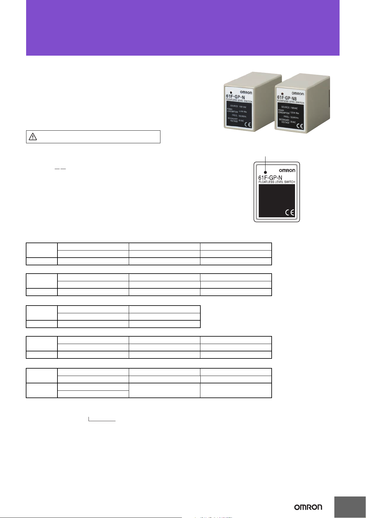
Floatless Level Switch (Compact, Plug-in Type)
Refer to Safety Precautions for Floatless Level
Controllers.
Position of LED indicator
21
61F-GP-@@
Example: 61F-GP-N [220 VAC]
Desired supply voltage
61F-GP-N@
Space-saving Design Ideal for Control Panel
Downsizing. Easy Maintenance.
• Compact: 49.4 × 38 × 84 mm (H×W×D).
• Easy identification of operating status with LED operation indicator.
• Independent DPDT contacts on 11-Pin Models.
• CE marking and UL/CSA compliance.
■ Model Number Legend
1. No. of Pins 2. Type
N: 11 pins
N8: 8 pins
Blank: General-purpose
L 2KM: Long-distance (for 2 km)
L 4KM: Long-distance (for 4 km)
H: High-sensitivity
D: Low-sensitivity
R: Two-wire
T: High-temperature
CSM_61F-GP-N@_DS_E_7_2
■ Ordering Information
Type General-purpose Long-distance (for 2 km) Long-distance (for 4 km)
Model Model Model
11-pin 61F-GP-N 61F-GP-NL 2KM 61F-GP-NL 4KM
Type High-sensitivity Low-sensitivity Two-wire
Model Model Model
11-pin 61F-GP-NH 61F-GP-ND 61F-GP-NR
Type Tropical environments High-temperature
Model Model
8-pin 61F-GP-N-TDL 61F-GP-NT
Type General-purpose Long-distance (for 2 km) Long-distance (for 4 km)
Model Model Model
8-pin 61F-GP-N8 61F-GP-N8L 2KM 61F-GP-N8L 4KM
Type High-sensitivity Low-sensitivity Two-wire
Model Model Model
8-pin 61F-GP-N8H 61F-GP-N8D 61F-GP-N8R
61F-GP-N8HY
Note: When ordering, specify the desired operating voltage at the end of the model number.
1
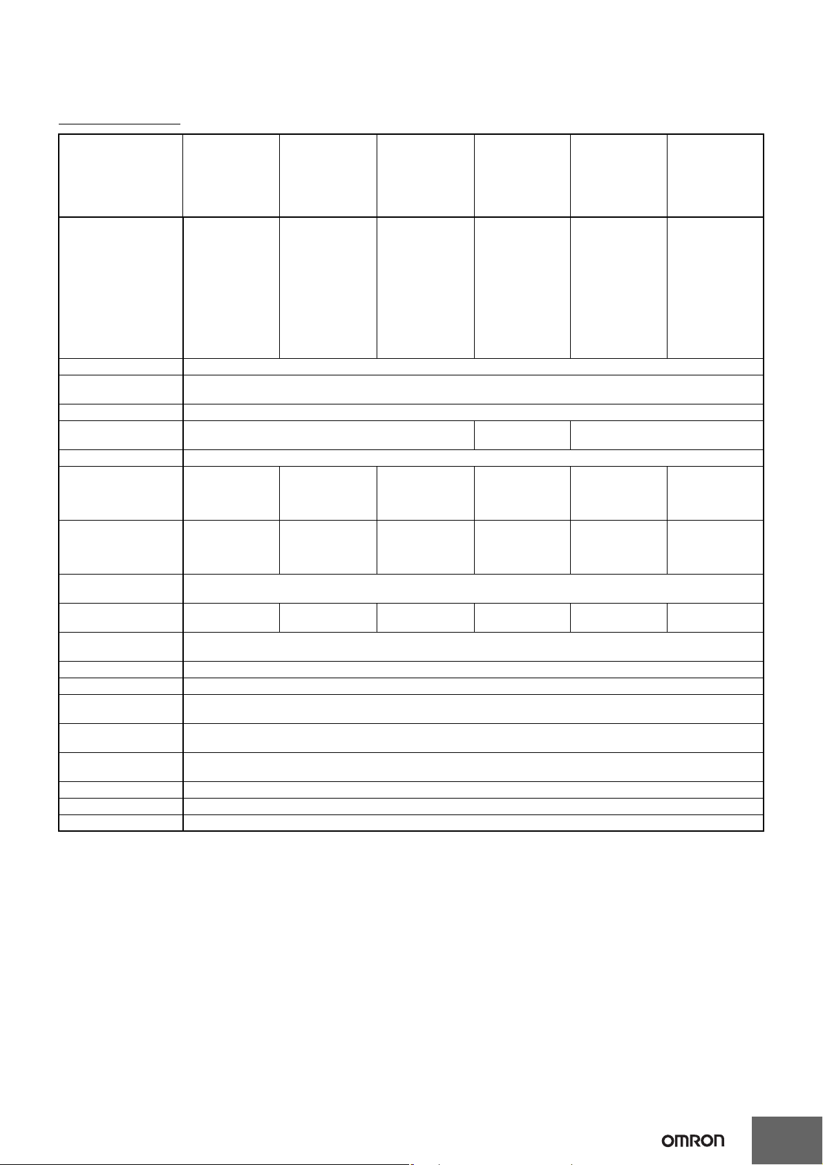
■ Compact Plug-in Models (11-pin Type)
Specifications
61F-GP-N@
Item General-purpose
Controlling materials
and operating conditions
Supply voltage 24, 100, 110, 120, 200, 220, 230 or 240 VAC; 50/60 Hz
Operating voltage
range
Interelectrode voltage 8 VAC
Interelectrode current Approx. 1 mA AC max. Approx. 0.12 mA
Power consumption Approx. 3.5 VA max.
Interelectrode operate
resistance
Interelectrode release
resistance
Response time Operate:80 ms max.
Cable length
(see note 1)
Control output 1 A, 250 VAC (Inductive load: cosφ = 0.4)
Ambient temperature Operating:–10 to 55°C (–10 to 70°C for high-temperature controller)
Ambient humidity Operating:45% to 85% RH
Insulation resistance
(see note 2)
Dielectric strength
(see note 2)
Life expectancy Electrical: 100,000 operations min.
Weight Approx. 155 g
Accessories Hold-down clip PFC-N8
Approved standards UL508, CSA C22.2 No.14, EN61010-1, EN61326-1 Industrial electromagnetic environment
Controller
61F-GP-N
For control of ordinary purified water
or sewage water
85% to 110% of rated voltage
0 to approx. 4 kΩ 0 to approx. 4 kΩ 0 to approx. 1.3 kΩ
Approx. 15 k to ∞ΩApprox. 15 k to ∞Ω4 k to ∞Ω (for 2
Release:160 ms max.
1 km max. 600 m max. 2 km max.
3 A, 250 VAC (Resistive load)
100 MΩ min. (at 500 VDC)
2000 VAC, 50/60 Hz for 1 min.
Mechanical: 5,000,000 operations min.
High-
temperature
Controller
61F-GP-NT
For control of ordinary purified water
or sewage where
operating ambient
temperature is
high.
Long-distance
Controllers
61F-GP-NL 2KM
(for 2 km)
61F-GP-NL 4KM
(for 4 km)
For control of ordinary purified water
in cases where the
distance between
sewage pumps
and water tanks or
between receiver
tanks and supply
tanks is long or
where remote control is required.
(for 2 km)
0 to approx. 0.5 kΩ
(for 4 km)
km)
2.5 k to ∞Ω (for 4
km)
4 km max.
High-sensitivity
Controller
61F-GP-NH
(see note 4)
For control of liquids with high specific resistance
such as distilled
water
AC max.
Approx. 10 kΩ to
approx. 40 kΩ
(see note 3)
Approx. 100 k to ∞ΩApprox. 4 k to ∞Ω Approx. 15 k to
50 m max. 1 km max. 800 m max.
Low-sensitivity
Controller
61F-GP-ND
For control of liquids with low specific resistance
such as salt water,
sewage water,
acid chemicals, alkali chemicals
Approx. 1 mA AC max.
0 to approx.
kΩ
1.3
Two-wire
Controller
61F-GP-NR
For control of ordinary purified water
or sewage water
used in combination with Two-wire
Electrode Holder
(incorporating a
resistor of 6.8 kΩ)
0 to
app
rox. 2 kΩ
∞Ω
Note: 1. The length when using completely insulated, 600-V, 3-conductor (0.75 mm2) cabtire cables. Usable cable lengths will become shorter as
the cable diameter or number of conductors becomes larger. For details, refer to Safety Precautions for Floatless Level Controllers.
2. The insulation resistance and dielectric strength indicate values between power terminals and Electrode terminals, between power
terminals and contact terminals, and between Electrode terminals and contact terminals. For details, refer to Safety Precautions for
Floatless Level Controllers.
3. Possible to use with 15 kΩ or less, however, this may cause reset failure.
4. 61F-GP-NH High-sensitivity Controller uses advanced operation.
When the power supply voltage is applied, if there are some liquids between the electrodes (ground and operation electrodes), the internal relay will not operate.
When the power supply voltage is applied, if there are no liquids between the electrodes (ground and operation electrodes), the internal
relay will operate.
If the advanced operation does not satisfy applications, consider using 61F-N8HY controller which uses sequential operation.
2
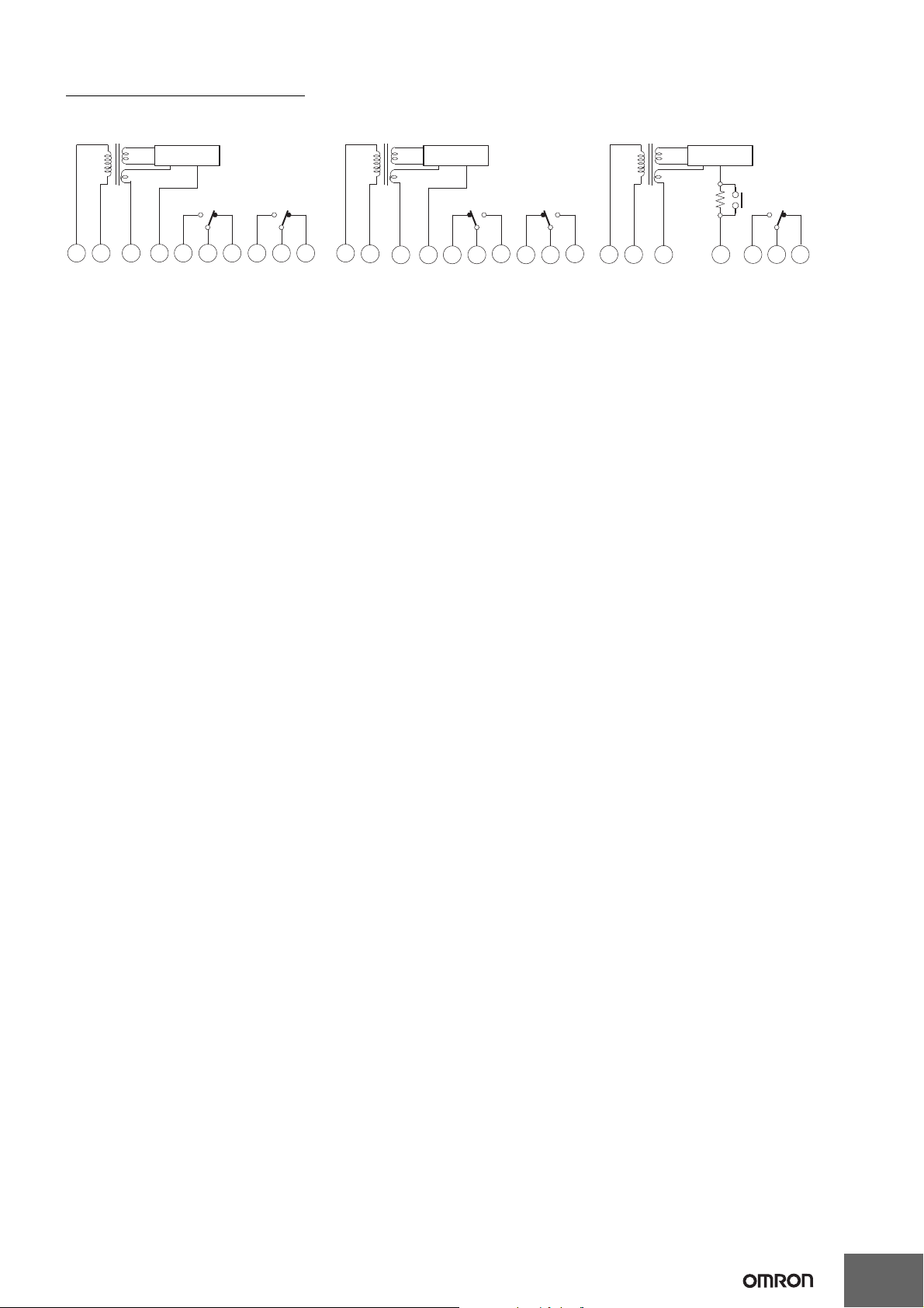
Internal Circuit Diagrams
61F-GP-N/-NT/-NL/-ND 61F-GP-NR61F-GP-NH
3 9 14 1011
U
24 V
8 V
Control circuit
S0S1E
3
5
E
1Ta1Tc1Tb1
867
U
Ta2Tc2Tb
2
3 9 14 1011
U
24 V
8 V
Control circuit
S0S1E
3
5
E
1Ta1Tc1Tb1
867
U
Ta2Tc2Tb
2
3
9
1
4
1011
U
24 V
8 V
Control circuit
S0S1E
3
5
E
1Ta1Tc1Tb1
U
Power supply Power supply Power supply
(See note.) (See note.)
Note: When applying a self-holding circuit, short between terminals 5 and 6 and use terminal 7 as E2.
61F-GP-N@
3
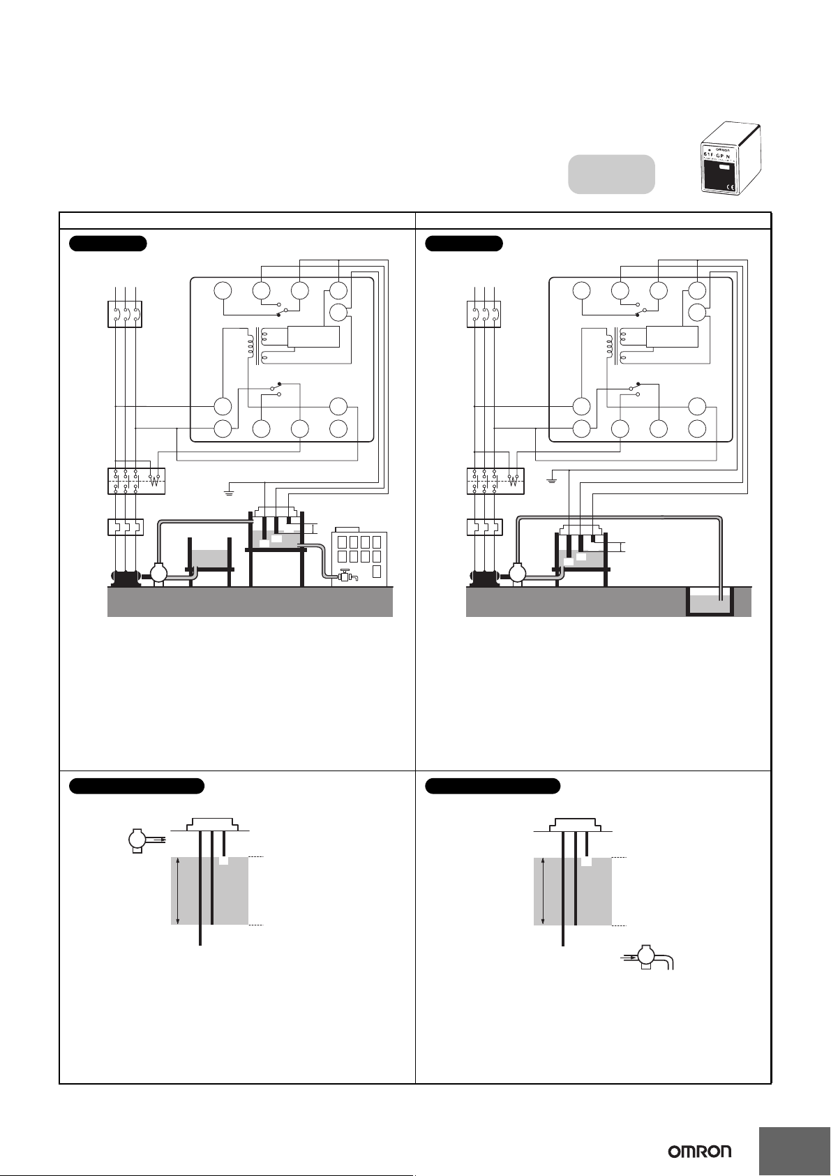
■ Connections
Compact, Plug-in Type
61F-GP-N
Dimensions:
page 14
Automatic Water Supply and
Drainage Control
Water supply
source
MCCB
RSMT
Commercial Voltage
61F-GP-N
PS-3S
Stop
3
9
E2
E3
E1
P
Start
8 V
Power
supply
0 V
U
U
U
24 V
Control
circuit
(See note.)
4
8 765
10 11 1 2
Contactor
Water
tank
Motor
protection
relay
Note: Be sure to ground the common Electrode E3 (the
longest Electrode).
Connection Sockets
PF113A (Front-connecting)
PL11 (Rear-connecting)
Connect terminal 1 to the contactor’s coil terminal.
Note: The power supply depends on the specifications of the
model.
Connections
Reservoir
MCCB
RSMT
Commercial Voltage
61F-GP-N
PS-3S
39
E2
E3
E1
P
8 V
0 V
U
U
U
24 V
Control
circuit
(See note.)
4
8 765
10 11 1 2
Start
Stop
Contactor
Power
supply
Motor
protection
relay
Waste-
water
tank
Note: Be sure to ground the common Electrode E3 (the
longest Electrode).
Connection Sockets
PF113A (Front-connecting)
PL11 (Rear-connecting)
Connect terminal 1 to the contactor’s coil terminal.
Note: The power supply depends on the specifications of the
model.
Connections
E1
E2
E3
P
Water
supply
(Indicator ON)
Pump OFF
Pump ON
(Indicator OFF)
The pump stops when the water level reaches E1 (indicator ON)
and starts when the water level drops below E
2 (indicator OFF).
Principles of Operation
E
1
E
2
E
3
Water drainage
(Indicator ON)
Pump OFF
Pump ON
(Indicator OFF)
P
The pump starts when the water level reaches E1 (indicator ON)
and stops when the water level drops below E
2 (indicator OFF).
Principles of Operation
Automatic Water Supply Control Automatic Drainage Control
61F-GP-N@
4

Liquid Level Indication
Liquid Level Indication
(Connection Example)
Compact, Plug-in Type
61F-GP-N
Dimensions:
page 14
E1
E2
E3
E4
Water supply
source
Intermediate
Upper limit
Lower limit
MCCB
RSMT
Commercial Voltage
P
PS-4S
U
U
61F-GP-N
Lower limit Intermediate Upper limit
56
7
8
4
8 V
Power
supply
Power
supply
Power
supply
0 V
24 V
10
3
9
12
11
Control
circuit
U
U
U
61F-GP-N
5
6
7
8
4
8 V
0 V
24 V
10
3
9
12
11
Control
circuit
U
U
U
61F-GP-N
5
6
7
8
4
8 V
0 V
24 V
10
3
9
12
11
Control
circuit
U
(See note.)
Water
tank
Note: The power supply phases (terminals 3 to 9) can be matched to use the same ground for the
common Electrode (the longest Electrode, terminal 4).
Connections
• Terminals 6 and 7, and terminals 10 and 11 on the lower -limit 61F-GP-N are shorted when the water level reaches E3 (indicator ON).
• Terminals 6 and 7, and terminals 10 and 11 on the intermediate 61F-GP-N are shorted when the water level reaches E
2 (indicator ON).
• Terminals 6 and 7, and terminals 10 and 11 on the upper-limit 61F-GP-N are shorted when the water level reaches E
1 (indicator ON).
Principles of Operation
61F-GP-N@
5
 Loading...