

Page 1
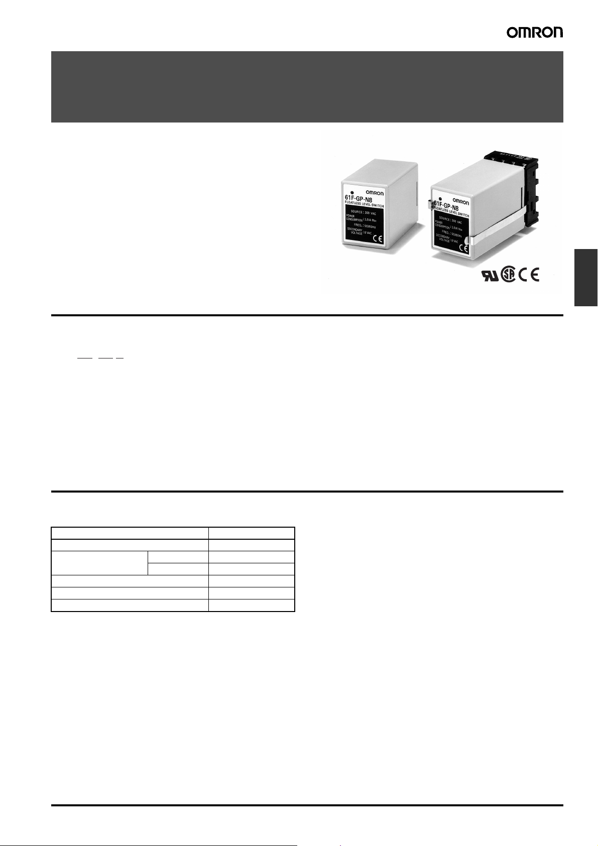
Conductive Level Controller
61F-GP-N8
Compact Plug-in Level Controllers for Single
or Two-point Level Control of Conductive
Materials (Liquids and Solids)
• Wide range of models: long-distance, high and low-sensitivity,
and two-wired types available.
• 24/100/110/120/200/220/230/240 VAC operation possible.
• Easy installation on DIN track.
• Low-voltage (AC) electrodes.
• Red LED operation indicator provided.
• Conforms to EMC and LVD Directives.
• UL/CSA approved.
Model Number Structure
■ Model Number Legend
61F-GP-N8@
1 2 3
1. Plug-in Type
2. Compact 8-pin Type
Level
Controllers
3. Applications
None: General-purpose type
L: Long-distance type
H: High-sensitivity type (reverse acting)
HY: High-sensitivity type (standard acting)
D: Low-sensitivity type
R: Two-wired type
Ordering Information
■ List of Models
Application Model number
General-purpose type 61F-GP-N8
Long-distance type 2 km 61F-GP-N8L 2KM
4 km 61F-GP-N8L 4KM
High-sensitivity type 61F-GP-N8H
Low-sensitivity type 61F-GP-N8D
Two-wired type 61F-GP-N8R
Conductive Level Controller 61F-GP-N8 E-5
Page 2
■ Accessories (Order Separately)
Selection Guide for Electrode Holders and Separators
Electrode Holders
Applications For city water and other
Mounting style Flange Screw Flange Screw
Insulator material Phenol resin Phenol resin Ceramics Teflon
Max. temperature 70°C150°C (without water drips or vapor on the
No. of
electrodes
general-use electrodes.
Easy-to-replace separate versions facilitate
maintenance of electrodes.
1 --- --- BF-1 BS-1
3 PS-3S PS-31 --- ---
When mounting space is
limited. Special 3-pole
holder of small size and
light weight. Ideal for soft
drink vendors, etc., where
only limited space is available.
For low specific liquids. Used for sewage,
sea water, etc., having a low specific resistance. In sewage use, electrode holders
must be installed 10 to 20 cm apart from
one another. For acids, alkalis and sea water, electrode holders may be as much as
1 meter apart to operate properly.
surface of the electrode holder)
When resistance to high
pressure is required. Ideal for use in tanks where
temperature or pressure
inside the tank is high,
e.g. 250°C
250°C (without water
drips or vapor on the surface of the electrode
holder)
Electrode Separators
No. of electrodes Model
1 F03-14 1P
3 F03-14 3P
Selection Guide for Electrodes, Connecting, and Lock Nuts
Applicable liquids Material Models for individual electrode assembly components
Electrode (1m long) Connecting nut Lock nut
Purified city water,
industrial water,
sewage
Purified city water,
industrial water,
sewage, dilute
alkaline solution
Equivalent
to SUS 304
(AISI-304)
SUS316
(AISI-316)
Model Indication
F03-01 SUS201 1 line F03-02 SUS201 --- F03-03 SUS201 ---
F03-01 SUS316 2 lines F03-02 SUS316 6 F03-03 SUS316 316
mark
Model Inscription Model Inscription
E-6 Conductive Level Controller 61F-GP-N8
Page 3
Specifications
■ Ratings and Characteristics
Model/Items General-purpose
Controlling materials and
operating conditions
Supply voltage 24, 100, 110, 120, 200, 220, 230 or 240 VAC; 50/60 Hz
Operating voltage range 85% to 110% of rated voltage
Interelectrode voltage 8 VAC 24 VAC 8 VAC
Interelectrode current Approx. 1 mA AC max. Approx.
Power consumption Approx. 3.5 VA max.
Interelectrode operate
resistance
Interelectrode release
resistance
Response time Operate: 80 ms max.
Cable length
(see note 2)
Control output 1 A, 250 VAC (Inductive load: cosφ = 0.4)
Ambient temperature Operating: −10°C to 55°C
Ambient humidity Operating: 45% to 85% RH
Insulation resistance
(see note 3)
Dielectric strength
(see note 4)
Life expectancy Electrical: 100,000 operations min.
Note: 1. The relay in the 61F-GP-N8H de-energizes when there is water present across the electrodes, whereas the relay in the 61F-GP-N8HY
energizes when there is water present across the electrodes.
2. The length when using completely-insulated, 600-V, 3-conductor (0.75 mm
as the cable diameter or number of conductors becomes larger.
3. The insulation resistance and dielectric strength indicate values between power terminals and electrode terminals, between power ter-
minals and contact terminals, and between electrode terminals and contact terminals.
4. Possible to use with 10 kΩ or less, however, this may cause reset failure.
Controller
61F-GP-N8
For control of ordinary
purified water or sewage water
Approx. 0 to 4 kΩ Approx. 0 to 1.3 kΩ
Approx. 15 k to ∞Ω Approx. 4 k to ∞Ω (for
Release: 160 ms max.
1 km max. 2 km max.
3 A, 250 VAC (Resistive load)
100 MΩ max. (at 500 VDC)
2000 VAC, 50/60 Hz for 1 min.
Mechanical: 5,000,000 operations min.
Long-distance
Controllers
61F-GP-N8L 2KM
(for 2 km)
61F-GP-N8L 4KM
(for 4 km)
For control of ordinary
purified water in cases where the distance
between sewage
pumps and water
tanks or between receiver tanks and supply tanks is long or
where remote control
is required.
(for 2 km)
Approx. 0 to 0.5 kΩ
(for 4 km)
2 km)
Approx. 2.5 k to ∞Ω
(for 4 km)
4 km max.
High-sensitivity
Controllers
61F-GP-N8H
61F-GP-N8HY
(see note 1)
For control of liquids
with high specific resistance such as distilled water
0.4 mA AC max.
Approx. 15 kΩ to
70 kΩ
(see note 3)
Approx. 300 k to ∞Ω Approx. 4 k to ∞Ω Approx. 15 k to ∞Ω
50 m max. 1 km max. 800 m max.
2
) cabtyre cables. Usable cable lengths will become shorter
Low-sensitivity
Controller
61F-GP-N8D
For control of liquids
with low specific resistance such as salt
water, sewage water,
acid chemicals, alkali
chemicals
Approx. 1 mA AC max.
Approx. 0 to 1.3 kΩ Approx. 0 to 2 kΩ
Two-wired
Controller
61F-GP-N8R
For control of ordinary
purified water or sewage water used in
combination with twowired-type electrode
holder (incorporating
a resistor of 6.8 kΩ)
Level
Controllers
Conductive Level Controller 61F-GP-N8 E-7
Page 4

Connections
■ Internal Circuit Diagrams
61F-GP-N8/-N8L/-N8D/-N8HY 61F-GP-N8H
Power
supply
24 V
Control circuit
8 V (see note)
Note: 24 V for the 61F-GP-N8HY.
Power
supply
24 V
Control circuit
24 V
■ Automatic Water Supply and Drainage Control
61F-GP-N8R
Power
supply
24 V
Control circuit
8 V
2
1. Water Supply
• Connect electromagnetic switch coil terminal A to terminal 2.
• The pump stops when the water level reaches E1 and starts when
the water level drops below E2.
200-VAC power supply
MCCB
(See note 1
below.)
Contactor
THR
(See note 2
below.)
Reservoir
61F-GP-N8
200 V
Tank
2. Drainage
• Connect the electromagnetic switch coil terminal A to terminal 3.
• The pump starts when the water level reaches E1 and stops when
the water level drops below E2.
0 V
8 V
Control circuit
24 V
PS-3S
Stop
Start
Note: 1. The diagram shows the connections for water supply. When draining, change the connection from terminal 2 to terminal 3.
2. The earth terminal must be earthed.
E-8 Conductive Level Controller 61F-GP-N8
Page 5

Operation
The Conductive Level Controller consists of a plug-in controller connected to a set of stainless steel probes. These are cut to length and
inserted vertically into the liquid. A low voltage is applied between
these probes and the earth probe (or tank, if it is electrically conductive). The water provides a current between the earth probe and the
high-level probe. The output relay in the Controller is energized when
the water level reaches the high-level probe and de-energized when
the water level falls below it.
For two-point control a low-level probe is used as well. In this case
the relay does not de-energize until the water level falls below the
low-level probe. Using the low-level probe allows a wide differential
between switching a pump on and off, and can avoid excessive pump
operation during tank emptying or filling. If this differential is not
required, the low-level probe need not be connected.
Surge Suppressor Unit (61F-03B/04B)
A high-capacity protective device is available which protects 61Fseries Floatless Level Controllers against faults arising from electrical surges (such as indirect strokes of lightning) when the Controllers
are employed in elevated water tanks or in high-altitude locations.
Specifications
Discharge start voltage 90 V ±20 VDC
Impulse withstand voltage 200,000 V (1 x 40 µs)
Impulse withstand current 6,000 A (1 x 40 µs)
Internal Connections
61F-03B
61F-04B
3. When connecting the Surge Suppressor Unit, wire as shown in
the following example (with three electrodes).
Ground
E3
E2
61F-03B
Level
Controllers
Ground
E1
Precautions
1. Mount the Surge Suppressor Unit as close to the Controller as
possible.
2. When grounding the Surge Suppressor Unit in the vicinity of the
Controller, connect the ground side of the Surge Suppressor Unit
to electrode E3.
Long distance
61F-03B
Ground
Connection Sockets
PF113A-E Track-mounted Socket
PL11 Back-connecting Socket
Conductive Level Controller 61F-GP-N8 E-9
Page 6

Dimensions
Note: All units are in millimeters unless otherwise indicated.
Electrode Holders
PS-@S
9-dia. rubber
bushing (inner)
PF2 parallel thread
(effective dia.: 58.135)
80
13
40
20
Mounting Holes Screw Holes
PS-3S/-3SR PS-4S/-4SR PS-5S/-5SR
34 dia.
E2
92
26
E1
E3
80
E2
E3
E1
E4
61F-GPN8
PF083A-E
E3
E4
91
E2
E1
PS-31
Dust preventive rubber cap (optional)
BF-1
Used with coupling Used with mounting bracket
PF2
38.5
32
11
712
PF1/2 Parallel thread
65-dia. hole
11 dia.
4 dia.
Electrode
SUS304
M3
3
Rubber
packing
(see note)
26
29.5 dia.
Note: Standard holder construction includes three integral 300-mm-long elec-
trodes. However, a model having 1,000-mm-long electrodes is available
on request.
17 14
(49)
72
Cast iron
Two M5 x 25
20 dia.
18
23
mounting
screws
Terminal bolt
SUS201 (M6)
Nut (M6)
33
4860
dia.
Mounting Holes
PF1/2
26-dia. hole
Two, 6-dia. holes
48
E-10 Conductive Level Controller 61F-GP-N8
Page 7

BS-1
Terminal bolt
SUS304 (M4) P=0.7
Width across flats: 20
M18
P = 1.5
Two M4
P = 0.7
24 dia.
Nut (iron)
12 39
5150
101
Electrode Separators
F03-14 1P (for Single Pole) F03-14 3P (for Three Poles)
6.5 dia.
28 dia.
Three, 7 dia.
41 dia.
Connecting Sockets
Track Mounted Socket
PF083A-E
Eight, M3.5 x 7
sems screws
52 max.
7±0.2
Two, 4.2-dia.
holes
25 dia.
Terminal Arrangement/
Internal Connections
(Top View)
M18 P=1.5
(fine screw thread)
20
Level
Controllers
Mounting Holes
Two, M4 or 4.5-dia. holes
Back Connecting Socket
PL08
50.5 max.
41 max.
35 max.
30 dia.
Approx. 20.5
21 max.
Two, 2-dia. holes
Internal Connections
(Bottom View)
Two, 3.5-dia. or M3
socket mounting holes
Mounting HolesTerminal arrangement/
Two, 3.5-dia. or
M3 Controller
mounting holes
31-dia.
hole
Conductive Level Controller 61F-GP-N8 E-11
Page 8

Holding Brackets
To mount the 61F-GP-N8 Conductive Level Controller on the
PF083A Track Mounted Socket, use the PFC-N8 Mounting Brackets
attached to the Socket as an accessory.
PFC-N8
Approx.
80
Surge Suppressor Unit
61F-03B
61F-04B
61F-03B
61F-04B
PF113A-E
Application Examples
• Level control in tanks, reservoirs, sewage plants, underground
wells, mixing plants etc.
• Level control for element protection in pipes, channels, and irriga-
tion systems.
• Flow detection in pipes, channels, and irrigation systems.
• Ice bank control in cold drink dispensers, ice makers, water chillers,
bulk milk tanks, etc.
■ Application
When using electrodes in sea water or sewage, provide a sufficient
interval (normally 1 m) between the electrodes. If the sufficient interval cannot be provided, employ a low-sensitivity-type Floatless Level
Controller.
When taping one of the electrodes to prevent it from contacting the
other electrodes in water, do not tape the electrode entirely but leave
at least 100 mm of its end uncovered.
When the required length of the electrode is more than 1 m, use a
separator at each joint of two electrodes so as to prevent the electrodes from contacting one another.
Note: Avoid use of the separators in dust-containing liquids.
Usually, electrodes are used in a set of three: long, medium, and
short. Connect the short electrode to E1, the medium electrode to
E2, and the long electrode to E3. Make E3 at least 50 mm longer
than E2.
• Dispensing of liquids by volume.
• Indication of liquid buildup due to filter blockages.
• Pollution/foul water detection for rivers, drains, etc.
• Alarm control warning of abnormal or dangerously high or low lev-
els.
E1
E2
E3
1 m1 m
Electrodes are in actual contact with the liquid. Standard electrodes
are made of stainless steel and usable in purified water, sea water,
sewage, acid (except acetic acid, sulfuric acid, etc.) and alkaline liquids, although they may corrode depending upon the temperature
and working conditions.
Min
50 mm
E-12 Conductive Level Controller 61F-GP-N8
Page 9

Note that the 61F-GP-N8 Conductive Level Controller is capable of
controlling liquids with specific resistances of up to 30 kΩ-cm when
the Controller employs a PS-3S electrode holder with the electrode(s) submerged to a depth of 30 mm max.
Kind of water Specific resistance Applicable type
City water 5 to 10 kΩ-cm Standard type
Well water 2 to 5 kΩ-cm Standard type
Industrial water 5 to 15 kΩ-cm Standard type
Rainwater 15 to 25 kΩ-cm Standard type
Sea water 0.03 kΩ-cm Low-sensitivity type
Sewage 0.5 to 2 kΩ-cm Low-sensitivity type
Distilled water 100 kΩ-cm or less High-sensitivity type
Over 100 kΩ-cm Consult OMRON
Precautions
■ How to Mount Electrodes
Connecting Electrodes to Electrode Holders
Electrode holder
Clamp screw
Connecting nut
1. Spin a lock nut and a spring
washer onto the electrode.
Lock nut
Electrode
2. Fully fit the electrode into the
connecting nut attached to the
electrode holder.
3. Tighten the electrode with
the two clamp screws.
Spring washer
4. Secure the connecting
nut by tightening the lock
nut and spring washer.
Connecting One Electrode to Another
Electrode
2. Fully fit the
electrode into the
connecting nut
attached to the
electrode holder.
Spring
washer
Lock nut
Spring washer
Connecting nut
3. Tighten the electrode with
the two clamp screws.
4. Secure the connecting
nut by tightening the lock
nut and spring washer.
Level
Controllers
1. Spin a lock nut and a spring
washer onto the electrode.
Conductive Level Controller 61F-GP-N8 E-13
Page 10

ALL DIMENSIONS SHOWN ARE IN MILLIMETERS.
To convert millimeters into inches, multiply by 0.03937. To convert grams into ounces, multiply by 0.03527.
Cat. No. F043-E1-02
In the interest of product improvement, specifications are subject to change without notice.
E-14 Conductive Level Controller 61F-GP-N8
 Loading...