

Page 1

Cat. No. W485-E1-02
3G8F7-CRM21 (for PCI Bus)
3G8F8-CRM21 (for CompactPCI Bus)
TM
CompoNet Master Board
for PCI Bus / CompactPCI Bus
USER’S MANUAL
Page 2

Trademarks and Copyrights
Microsoft, Windows, Windows 2000, Windows XP, Windows Vista, Windows 7, Visual Basic, and
Visual C++ are registered trademarks of the Microsoft Corporation.
C++Builder is the registered trademark of the Embarcadero Technologies, Inc.
ODVA, CIP, CompoNet, DeviceNet, and EtherNet/IP are trademarks of the Open DeviceNet Vendor
Association, Inc.
Other product names and company names in this manual are trademarks or registered trademarks of
their respective companies.
The copyright of the CompoNet Master Boards for PCI Bus and for CompactPCI Bus, and related
software belongs to OMRON Corporation.
Page 3

3G8F7-CRM21 (for PCI Bus)
3G8F8-CRM21 (for CompactPCI Bus)
CompoNet Master Board for PCI Bus / CompactPCI Bus
TM
User’s Manual
Revised September 2013
Page 4

iv
Page 5

Notice:
OMRON products are manufactured for use according to proper procedures by a qualified operator
and only for the purposes described in this manual.
The following conventions are used to indicate and classify precautions in this manual. Always heed
the information provided with them. Failure to heed precautions can result in injury to people or
damage to property.
DANGER
WARNING
Caution
Indicates an imminently hazardous situation which, if not avoided, will result in death or
serious injury . Additionally, there may be severe property damage.
Indicates a potentially hazardous situation which, if not avoided, could result in death or
serious injury . Additionally, there may be severe property damage.
Indicates a potentially hazardous situation which, if not avoided , may result in minor or
moderate injury, or property damage.
OMRON Product References
All OMRON products are capita lized in this man ual. T he w ord "Unit" is also capitaliz ed when it r ef ers t o
an OMRON product, regardless of whether or not it appears in the proper name of the product.
The abbreviation "Ch," which appears in some parts of this manual and on some displays and on
OMRON products, has two meanings which must be distinguished in context. In one case, it means
"word" as an aggregation of da ta, an d is a b br eviated "Wd". In other case, it refers to a p hysical input or
output channel. In latter case, when a model has two input channels, they are referred to as Input 1
and Input 2.
The abbreviation "PC" refers to personal computers while "PLC" means Programmable Controller.
Visual Aids
The following headings appear in the left column of the manual to help you locate different types of
information.
Precautions for Safe Use
Supplementary c omments on what to do or avoid doing, to use the product
safely
Precautions for Correct Use
Supplementary comm ents on what to do or avoid doing, to prevent failure to
operate, or undesirable eff ect on product performance
Note Notes in the document refer to equivalent content to the Precautions for
Correct Use or to Precautions for Safe Use.
It also indicates information of particular interest for efficient and convenient
operation of the product.
1,2,3... 1. Indicates lists of one sort or another , such as procedures, checklists, etc.
v
Page 6

OMRON, 2009
r
f
All rights reserved. No part of this publication may be reproduced, stored in a retrieval system, or transmitted, in any form, o
by any means, mechanical, electronic, photocopying, recording, or otherwise, without the prior written permission o
OMRON.
No patent liability is assumed with respect to the use of the information contained herein. Moreover, because OMRON is
constantly striving to improve its high-quality products, the information contained in this manual is subject to change without
notice. Every precaution has been taken in the preparation of this manual. Nevertheless, OMRON assumes no responsibility
for errors or omissions. Neither is any liability assumed for damages resulting from the use of the information contained in
this publication.
vi
Page 7

TABLE OF CONTENTS
PRECAUTIONS. . . . . . . . . . . . . . . . . . . . . . . . . . . . . . . . . . . xv
1 Intended Audience . . . . . . . . . . . . . . . . . . . . . . . . . . . . . . . . . . . . . . . . . . . . . . . . . . . . . . . . xvi
2 General Precautions . . . . . . . . . . . . . . . . . . . . . . . . . . . . . . . . . . . . . . . . . . . . . . . . . . . . . . . xvi
3 Safety Precautions . . . . . . . . . . . . . . . . . . . . . . . . . . . . . . . . . . . . . . . . . . . . . . . . . . . . . . . . xvii
4 Operating Environment Precautions. . . . . . . . . . . . . . . . . . . . . . . . . . . . . . . . . . . . . . . . . . . xvii
5 Application Precautions . . . . . . . . . . . . . . . . . . . . . . . . . . . . . . . . . . . . . . . . . . . . . . . . . . . . xvii
6 Conformance with the EC Directives. . . . . . . . . . . . . . . . . . . . . . . . . . . . . . . . . . . . . . . . . . xx
SECTION 1
Outline of CompoNet and CompoNet Master Board . . . . . 1
1-1 Overview of the CompoNet Network. . . . . . . . . . . . . . . . . . . . . . . . . . . . . . . . . . . . . . . . . . 2
1-2 Overview of the CompoNet Master Board. . . . . . . . . . . . . . . . . . . . . . . . . . . . . . . . . . . . . . 3
1-3 Component Name and Function. . . . . . . . . . . . . . . . . . . . . . . . . . . . . . . . . . . . . . . . . . . . . . 4
1-4 LED Indication. . . . . . . . . . . . . . . . . . . . . . . . . . . . . . . . . . . . . . . . . . . . . . . . . . . . . . . . . . . 6
1-5 Network Construction Procedure. . . . . . . . . . . . . . . . . . . . . . . . . . . . . . . . . . . . . . . . . . . . . 7
1-6 Board Preparation Procedure . . . . . . . . . . . . . . . . . . . . . . . . . . . . . . . . . . . . . . . . . . . . . . . . 8
1-7 Specifications . . . . . . . . . . . . . . . . . . . . . . . . . . . . . . . . . . . . . . . . . . . . . . . . . . . . . . . . . . . . 9
SECTION 2
Installation and Setup . . . . . . . . . . . . . . . . . . . . . . . . . . . . . . 11
2-1 Mounting a Board. . . . . . . . . . . . . . . . . . . . . . . . . . . . . . . . . . . . . . . . . . . . . . . . . . . . . . . . . 12
2-2 Installing the Drivers . . . . . . . . . . . . . . . . . . . . . . . . . . . . . . . . . . . . . . . . . . . . . . . . . . . . . . 14
2-3 Connecting the Communications Cables . . . . . . . . . . . . . . . . . . . . . . . . . . . . . . . . . . . . . . . 21
2-4 Connecting the Communications Power Supply Cables . . . . . . . . . . . . . . . . . . . . . . . . . . . 25
SECTION 3
Functions. . . . . . . . . . . . . . . . . . . . . . . . . . . . . . . . . . . . . . . . . 27
3-1 Settings at Communications Cycle Startup . . . . . . . . . . . . . . . . . . . . . . . . . . . . . . . . . . . . . 28
3-2 Access to I/O Data . . . . . . . . . . . . . . . . . . . . . . . . . . . . . . . . . . . . . . . . . . . . . . . . . . . . . . . . 30
3-3 Status . . . . . . . . . . . . . . . . . . . . . . . . . . . . . . . . . . . . . . . . . . . . . . . . . . . . . . . . . . . . . . . . . . 35
3-4 Explicit Messages. . . . . . . . . . . . . . . . . . . . . . . . . . . . . . . . . . . . . . . . . . . . . . . . . . . . . . . . . 37
3-5 Detailed Settings at Communications Cycle Startup . . . . . . . . . . . . . . . . . . . . . . . . . . . . . . 37
SECTION 4
Operation by API Functions . . . . . . . . . . . . . . . . . . . . . . . . . 41
4-1 Access to I/O Data . . . . . . . . . . . . . . . . . . . . . . . . . . . . . . . . . . . . . . . . . . . . . . . . . . . . . . . . 42
4-2 Detailed Setting at Communications Cycle Startup. . . . . . . . . . . . . . . . . . . . . . . . . . . . . . . 45
4-3 Explicit Messaging. . . . . . . . . . . . . . . . . . . . . . . . . . . . . . . . . . . . . . . . . . . . . . . . . . . . . . . . 46
4-4 Setting the Time Information . . . . . . . . . . . . . . . . . . . . . . . . . . . . . . . . . . . . . . . . . . . . . . . . 48
4-5 Implementing the Reset Request . . . . . . . . . . . . . . . . . . . . . . . . . . . . . . . . . . . . . . . . . . . . . 49
vii
Page 8

TABLE OF CONTENTS
4-6 Access to Detailed Status Group. . . . . . . . . . . . . . . . . . . . . . . . . . . . . . . . . . . . . . . . . . . . . . 50
4-7 PC Watchdog Timer. . . . . . . . . . . . . . . . . . . . . . . . . . . . . . . . . . . . . . . . . . . . . . . . . . . . . . . . 52
4-8 Board Hardware Error Notification. . . . . . . . . . . . . . . . . . . . . . . . . . . . . . . . . . . . . . . . . . . . 53
SECTION 5
Operation by Accessing to Shared Memory. . . . . . . . . . . . . 55
5-1 Basic Procedures . . . . . . . . . . . . . . . . . . . . . . . . . . . . . . . . . . . . . . . . . . . . . . . . . . . . . . . . . . 56
5-2 Communications Cycle Control Procedures . . . . . . . . . . . . . . . . . . . . . . . . . . . . . . . . . . . . . 58
5-3 Setting the Time Information. . . . . . . . . . . . . . . . . . . . . . . . . . . . . . . . . . . . . . . . . . . . . . . . .63
5-4 Implementing the Reset Request. . . . . . . . . . . . . . . . . . . . . . . . . . . . . . . . . . . . . . . . . . . . . . 63
5-5 PC Watchdog Timer. . . . . . . . . . . . . . . . . . . . . . . . . . . . . . . . . . . . . . . . . . . . . . . . . . . . . . . . 64
5-6 Board Hardware Error Notification. . . . . . . . . . . . . . . . . . . . . . . . . . . . . . . . . . . . . . . . . . . . 65
SECTION 6
Troubleshooting . . . . . . . . . . . . . . . . . . . . . . . . . . . . . . . . . . . 67
6-1 LED Indications and Error Handling. . . . . . . . . . . . . . . . . . . . . . . . . . . . . . . . . . . . . . . . . . . 68
6-2 Error Log . . . . . . . . . . . . . . . . . . . . . . . . . . . . . . . . . . . . . . . . . . . . . . . . . . . . . . . . . . . . . . . . 70
APPENDIX A
API Function Reference. . . . . . . . . . . . . . . . . . . . . . . . . . . . . 73
A-1 Function List . . . . . . . . . . . . . . . . . . . . . . . . . . . . . . . . . . . . . . . . . . . . . . . . . . . . . . . . . . . . . 74
A-2 Board Control API. . . . . . . . . . . . . . . . . . . . . . . . . . . . . . . . . . . . . . . . . . . . . . . . . . . . . . . . . 76
A-3 Communications Control API . . . . . . . . . . . . . . . . . . . . . . . . . . . . . . . . . . . . . . . . . . . . . . . . 77
A-4 Status Access API . . . . . . . . . . . . . . . . . . . . . . . . . . . . . . . . . . . . . . . . . . . . . . . . . . . . . . . . . 85
A-5 I/O Data Access API . . . . . . . . . . . . . . . . . . . . . . . . . . . . . . . . . . . . . . . . . . . . . . . . . . . . . . . 90
A-6 Explicit Messaging API. . . . . . . . . . . . . . . . . . . . . . . . . . . . . . . . . . . . . . . . . . . . . . . . . . . . . 93
A-7 PC Watchdog Timer API . . . . . . . . . . . . . . . . . . . . . . . . . . . . . . . . . . . . . . . . . . . . . . . . . . . . 97
A-8 Board Request Notification API . . . . . . . . . . . . . . . . . . . . . . . . . . . . . . . . . . . . . . . . . . . . . . 98
A-9 Errors Detectable by Functions . . . . . . . . . . . . . . . . . . . . . . . . . . . . . . . . . . . . . . . . . . . . . . . 100
APPENDIX B
Shared Memory Interface . . . . . . . . . . . . . . . . . . . . . . . . . . . 101
B-1 PCI Resources . . . . . . . . . . . . . . . . . . . . . . . . . . . . . . . . . . . . . . . . . . . . . . . . . . . . . . . . . . . . 102
B-2 PC I Register Specifications . . . . . . . . . . . . . . . . . . . . . . . . . . . . . . . . . . . . . . . . . . . . . . . . . .103
B-3 Shared Memory Area Specifications. . . . . . . . . . . . . . . . . . . . . . . . . . . . . . . . . . . . . . . . . . . 107
B-4 Command Specifications. . . . . . . . . . . . . . . . . . . . . . . . . . . . . . . . . . . . . . . . . . . . . . . . . . . .142
APPENDIX C
Communications Performance . . . . . . . . . . . . . . . . . . . . . . . 147
C-1 Remote I/O Communications Performance. . . . . . . . . . . . . . . . . . . . . . . . . . . . . . . . . . . . . . 148
viii
Page 9

TABLE OF CONTENTS
APPENDIX D
Sample Program . . . . . . . . . . . . . . . . . . . . . . . . . . . . . . . . . . . 153
D-1 Sample Program. . . . . . . . . . . . . . . . . . . . . . . . . . . . . . . . . . . . . . . . . . . . . . . . . . . . . . . . . . . 154
APPENDIX E
Installation and Setup. . . . . . . . . . . . . . . . . . . . . . . . . . . . . . . 155
E-1 CompoNet Network Specifications. . . . . . . . . . . . . . . . . . . . . . . . . . . . . . . . . . . . . . . . . . . . 156
E-2 Wiring Formations. . . . . . . . . . . . . . . . . . . . . . . . . . . . . . . . . . . . . . . . . . . . . . . . . . . . . . . . . 165
E-3 Wiring for a CompoNet Network . . . . . . . . . . . . . . . . . . . . . . . . . . . . . . . . . . . . . . . . . . . . . 167
E-4 Preparing and Mounting Flat Connectors on the Cables. . . . . . . . . . . . . . . . . . . . . . . . . . . . 180
E-5 Wiring for Power Supply. . . . . . . . . . . . . . . . . . . . . . . . . . . . . . . . . . . . . . . . . . . . . . . . . . . .195
ix
Page 10

TABLE OF CONTENTS
x
Page 11

About This Manual
This manual describes the installation and operation of the 3G8F7-CRM21 CompoNet Master Board
for PCI Bus and the 3G8F8-CRM21 CompoNet Master Board for CompactPCI Bus. The CompoNet
Master Board functions as the CompoNet Master Unit. There are two types: One is compatible with
PCI bus (model # 3G8F7-CRM21), and the othe r is compa tib le with Co mpactPCI b u s (model # 3G8 F8CRM21) .
Please read this manual carefully and be sure you understand the information provided before
attempting to install or operate a CompoNe t Master Board. Be sure to read th e pre caution s pro v ided i n
the following section. Also be sure to read the CompoNet Slave Unit Operation Manual (see following
table) together with this manual.
The manual contains the following sections:
Precautions provide general precautions for using the CompoNet Master Board and related devices.
Section 1 outlines the CompoNet and the CompoNet Master Board. Read this section carefully before
you use the CompoNet Master Board for the first time.
Section 2 outlines the installation and setup. It includes procedures to mount a Board, to install a
driver, and to connect the communications cables.
Section 3 describes the functions of the CompoNet Master Boards. There are basic and special
functions.
Section 4 describes the operations by API functions to control the Board in the Windows operation
systems.
Section 5 describes the operations by shared memory access to control the Board in operation
systems, other than Windows.
Section 6 describes the troubleshooting. It is recommended to read them first to prevent any errors
from occurring.
Appendix A describes the API functions.
Appendix B describes the shared memory interfaces.
Appendix C explains the communications performance.
Appendix D describes the sample program provided in the product package.
Appendix E describes the construction of a CompoNet Network.
It includes the network specifications, the wiring procedures and the preparation of Flat Connectors.
xi
Page 12

Related Manuals
Cat No. Model Name Description
W485
(this manual)
W457 CRT1
W456 CS1W-CRM21
3G8F7-CRM21
3G8F8-CRM21
CJ1WCRM21
CompoNet Master Board for
PCI Bus and for CompactPCI
Bus Operation Manual
CR1-series CompoNet
Slave Units and Repeater Unit
Operation Manual
CS/CJ-series CompoNet
Master Units Operation
Manual
TM
TM
Provides the specifications of
the CompoNet Master Board
Provides the specifications of
CompoNet Slave Units and
Repeater Units
TM
Provides an overview of
CompoNet Networks,
communications
specifications, wiring
methods, and CompoNet
Master Unit functions
WARNING
xii
The failure to read and understand the information provided in this manual may result in
personal injury or death, damage to the product or product failure. Please read each
section in its entirety, and be sure you understand the info rmation provided in th e section
and related sections before attempting any of the procedures or operations.
Page 13

Terms and Conditions Agreement
Read and understand this Manual
Please read and understand this catalog before purchasing the products. Please consult your
OMRON representative if you have any questions or comments.
Warranty, Limitations of Liability
Warranties
z Exclusive Warranty
Omron’s exclusive warranty is that the Products will be free from defects in materials and workmanship for a period of twelve months from the date of sale by Omron (or such other period
expressed in writing by Omron). Omron disclaims all other warranties, express or implied.
z Limitations
OMRON MAKES NO WARRANTY OR REPRESENTATION, EXPRESS OR IMPLIED, ABOUT
NON-INFRINGEMENT, MERCHANTABILITY OR FITNESS FOR A P AR TICULAR PURPOSE OF
THE PRODUCTS. BUYER ACKNOWLEDGES THAT IT ALONE HAS DETERMINED THAT THE
PRODUCTS WILL SUITABLY MEET THE REQUIREMENTS OF THEIR INTENDED USE.
Omron further disclaims all warranties and responsibility of any type for claims or expenses based
on infringement by the Products or otherwise of any intellectual property right.
z Buyer Remedy
Omron’s sole obligation hereunder shall be, at Omron’s election, to (i) replace (in the form originally shipped with Buyer responsible for labor charges for removal or replacement thereof) the
non-complying Product, (ii) repair the non-complying Product, or (iii) repay or credit Buyer an
amount equal to the purchase price of the non-complying Product; pro vided th at in no even t sha ll
Omron be responsible for warranty, repair, indemnity or any other claims or expenses regarding
the Products unless Omron’s analysis confirms that the Products were properly handled, stored,
installed and maintained and not subject to contamination, abuse, misuse or inappropriate modification. Return of any Products by Buyer must be approved in writing by Omron before shipment.
Omron Companies shall not be liable for the suitability or unsuitability or the results from the use
of Products in combination with any electrical or electronic components, circuits, system assemblies or any other materials or substances or environments. Any advice, recommendations or
information given orally or in writing, are not to be construed as an amendment or addition to the
above warranty.
See http://www.omron.com/global/ or contact your Omron representative for published information.
Limitation on Liability; Etc
OMRON COMP ANIES SHALL NOT BE LIABLE FOR SPECIAL, INDIRECT, INCIDENTAL, OR CONSEQUENTIAL DAMAGES, LOSS OF PROFITS OR PRODUCTION OR COMMERCIAL LOSS IN
ANY WAY CONNECTED WITH THE PRODUCTS, WHETHER SUCH CLAIM IS BASED IN CONTRACT, WARRANTY, NEGLIGENCE OR STRICT LIABILITY.
Further, in no event shall liability of Omron Companies exceed the individual price of the Product on
which liability is asserted.
xiii
Page 14

Application Considerations
Suitability of Use
Omron Companies shall not be responsible for conformity with any standards, codes or regulations
which apply to the combination of the Product in the Buyer’s application or use of the Product. At
Buyer’s request, Omron will provide applicable third party certification documents identifying ratings
and limitations of use which apply to the Product. This information by itself is not sufficient for a complete determination of the suitability of the Product in combination with the end product, machine,
system, or other application or use. Buyer shall be solely responsible for determining appropriateness of the particular Product with respect to Buyer’s application, product or system. Buyer shall take
application responsibility in all cases.
NEVER USE THE PRODUCT FOR AN APPLICATION INVOLVING SERIOUS RISK TO LIFE OR
PROPERTY WITHOUT ENSURING THA T THE SYSTEM AS A WHOLE HAS BEEN DESIGNED TO
ADDRESS THE RISKS, AND THAT THE OMRON PRODUCT(S) IS PROPERLY RATED AND
INSTALLED FOR THE INTENDED USE WITHIN THE OVERALL EQUIPMENT OR SYSTEM.
Programmable Products
Omron Companies shall not be responsible for the user’s programming of a programmable Product,
or any consequence thereof.
Disclaimers
Performance Data
Data presented in Omron Company websites, catalogs and other materials is provided as a guide for
the user in determining suitability and does not constitute a warranty. It may represent the result of
Omron’s test conditions, and the user must correlate it to actual application requirement s. Actual performance is subject to the Omron’s Wa rranty and Limitations of Liability.
Change in Specifications
Product specifications and accessories may be changed at any time based on improvements and
other reasons. It is our practice to change part numbers when published ratings or features are
changed, or when significant construction changes are made. However, some specification s of the
Product may be changed without any notice. When in doubt, special part numbers may be assigned
to fix or establish key specifications for your application. Please consult with your Omron’s representative at any time to confirm actual specifications of purchased Product.
Errors and Omissions
Information presented by Omron Companies has been checked and is believed to be accurate; however, no responsibility is assumed for clerical, typographical or proofreading errors or omissions.
xiv
Page 15

PRECAUTIONS
This section provides general precautions for use of the CompoNet Master Boards.
The information contained in this section is important for the safe, reliable application of the CompoNet Master
Board. You must read this section and understand the information contained before attempting to set up or
operate a CompoNet Network using CompoNet Master Boards.
1 Intended Audience . . . . . . . . . . . . . . . . . . . . . . . . . . . . . . . . . . . . . . . . . . . . . xvi
2 General Precautions . . . . . . . . . . . . . . . . . . . . . . . . . . . . . . . . . . . . . . . . . . . . xvi
3 Safety Precautions . . . . . . . . . . . . . . . . . . . . . . . . . . . . . . . . . . . . . . . . . . . . . xvii
4 Operating Environment Precautions. . . . . . . . . . . . . . . . . . . . . . . . . . . . . . . . xvii
5 Application Precautions . . . . . . . . . . . . . . . . . . . . . . . . . . . . . . . . . . . . . . . . . xvii
6 Conformance with the EC Directives. . . . . . . . . . . . . . . . . . . . . . . . . . . . . . . xx
6-1 Applicable Directives . . . . . . . . . . . . . . . . . . . . . . . . . . . . . . . . . . . . xx
6-2 Concepts. . . . . . . . . . . . . . . . . . . . . . . . . . . . . . . . . . . . . . . . . . . . . . xx
6-3 Conformity. . . . . . . . . . . . . . . . . . . . . . . . . . . . . . . . . . . . . . . . . . . . xx
xv
Page 16

Intended Audience 1
1 Intended Audience
This manual is intended for the following personnel to read and use. The
personnel must have knowledge of electrical systems and would therefore be
electrical engineers or the equivalent:
• Perso nn e l in char ge of intr o ducin g FA systems
• Perso nn e l in char ge of de sig ning FA systems
• Personnel in charge of managing FA systems and facilities
2 General Precautions
The user must operate the product according to the performance
specifications described in the operation manuals. Before using the product
under conditions that are not described in the manual or when applying the
product to nuclear control systems, railroad systems, aviation systems,
vehicles, combustion systems, medical equipment, amusement machines or
safety equipment, or to other systems, machines and equipment that may
have a se rious influen ce on lives and property if used improperly, consul t your
OMRON representative.
Be certain the ratings and performance characteristics of the product are
sufficient for the systems, machines and equipment, and be sure to provide
the systems, machines and equipment with double safety mechanisms.
This manual provides information for programming and operating the Unit. Be
sure to read this manual before attempting to use the Unit, and keep this
manual close at hand for reference during operation.
Be sure this manual is delivered to the persons actually using the CompoNet
Master Boards.
WARNING
It is extremely important that a PLC and all PLC Units be used for th e specified purpose
and under the specified conditions, especially in ap plications that can directly or indirect ly
affect human life. You must consult with your OMRON representative before applying a
PLC System to the above-mentioned applications.
xvi
Page 17

Safety Precautions 3
3 Safety Precautions
WARNING
WARNING
WARNING
WARNING
Caution
Caution
Do not attempt to take any Unit apart or touch the component inside while the power is
being supplied. Doing so may result in electric shock.
Do not touch any of the terminals or terminal blocks while the power is being supplied.
Doing so may result in electric shock.
Fail-safe measures must be taken by the user to ensure safe ty in the event of inco rrect,
missing or abnormal signals caused by broken signal lines, momentary power
interruptions or other causes. Serious accidents may result from abnormal operation if
proper measures are not provided.
Provide safety measures in external circuits (i.e., not in the personal computers) that
ensure safety of the system in any event of an abnormality due to malfunction of the PC
or another external factor affecting the PC operation. The failure to do so may result in
serious accidents. Emergency stop circuits, interlock circuits, limit circuits and similar
safety measures must be provided in external control circuits.
Confirm safety at the destination Sla ve Unit before changing it or transf erring par ameters
to another node. Changing or transferring any of these without confirming safety may
result in unexpected equipment operation.
A Slave Unit may change the output content if it faces a communications failure. When
you use outputting devices, confirm their operation specification on an event of
communications failure, and take the necessary safety measures.
4 Operating Environment Precautions
Caution
Do not operate the products in the following locations.
• Locations subject to direct sunlight
• Locations subject to temperatures or humidity outside the range
specified in the specifications
• Locations subject to condensation as the result of severe changes in
temperature
• Locations subject to corrosive or flammable gases
• Locations subject to dust (especially iron dust) or salts
• Locations subject to exposure to water, oil, or chemicals (including
acids)
• Locations subject to shock or vibration
5 Application Precautions
Observe the following precautions when using a CompoNet Network.
• When more than one CompoNet system use Flat Cables, always
separate the Flat Cables from each ot her by at least 5 mm regard less of
whether Flat Cable I or II is us ed. Do not b un dle the F lat Cables. This is to
prevent unstable operation of the system due to interference.
xvii
Page 18

Application Precautions 5
• Fail-safe measures must be taken by the customer to ensure safety in the
event of incorrect, missing or abnormal signals caused by broken signal
lines, momentary power interruption s or other causes.
• Configure the control circuits so that the power to the PC (near the
CompoNet Master Board) will be on after the power to the I/O Sla v e Units .
If the PC power supply is turned on first, normal operation will not be
ensured, even temporarily.
• Use the Boards within the communications distance and the number of
connectable Units as defined in the specifications.
• Do not attempt to disassemble, repair or modify any Units. Any attempt to
do so may result in a malfunction, fire or el ectric shock.
• When installing the Unit, ground to 100 Ω/min.
• Be certain all screws to fix the Board to the PC, as well as the screws on
connectors, cables and terminal blocks, are tightened to the torque
specified in the corresponding manual s. Incorrect tightening torque may
result in a malfunction.
• Be sure the Board on the PC is securely mounted.
• All installation and wiring must observe the instructions in this manual.
• Use correct wiring tools and components for wiring.
• Confirm the orientation and polarity before connecting the terminal blocks
or connectors.
• Do not supply electricity while a terminal block cover is open.
• Confirm voltage specifications before wiring the communications lines,
the power supplies or the I/O circuits. Incorrect specification may result in
a malfunction.
• Install exter nal breakers and take other safety measures against shortcircuiting in the external wiring. Insufficient safety measures against
short-circuiting may result in burning.
• Use crimp terminals for wiring. Do not connect bare stranded wires
directly to terminals. The connection of bare stranded wires may result in
burning.
• Double-check all wiring and switch settings before turning ON the power
supply. Incorrect wiring may result in burning.
• Be sure no waste metal enters the PC during the installation and wiring
work.
• Be certain the terminal blocks, connectors, expansion cables,
communications cables and other items with locking devices are properly
locked in place. Improper locking may result in a malfunction.
• Always use the power-supply voltages specified in the operation manual.
A malfunction or burning may occur as the result of incorrect voltage.
• Take appropriate measures to ensure that the specified power with the
rated voltage and frequency is supplied. Be particularly careful in places
where the power supply is unstable. An incorrect power supply may result
in a malfunction.
• Check the user program fo r proper execution before actually running it on
the Unit. The failure to check the program may result in unexpected
operation.
• Always tur n OFF the power supply to the personal computer, the Slave
Units and communications before attempting any of the following. The
failure to turn OFF the power supply ma y result in a malfunction or electric
shock.
xviii
Page 19

Application Precautions 5
• Mounting or removing a CompoNet Master Board
• Assembling devices
• Setting rotary switches
• Connecting cables or wiring the system
• Connecting or disconnecting the connectors
• Close the PC cover before wiring work. This is used to prevent wire waste
from entering the PC.
• Before touching a CompoNet Master Board, be sure to first touch a
grounded metallic object in order to discharge any static buildup. The
failure to do so may result in a malfunction or damage.
• When replacing parts, be sure to confirm that the rating of the new part is
correct. The failure to do so may result in a malfunction or burning.
• When transporting a CompoNet Master Board, use special packing boxes
and protect it from exposure to excessive vibration or impact during
transportation.
• Use the Board in the specified ambient operating temperature and
humidity.
• Store the Board in the specified ambient storage temper ature.
• Circuit boards have sharp edges such as leads of electric components.
Do not touch the parts where such components are mounted or the bac ks
of circuit boards by hand.
• Use only the specified communications cables.
• Do not extend connection distances beyond the ranges given in the
specifications.
• Observe the given precautions when wiring the communications cable.
• Separa te t he communications cables from the p ower lines or high-tension
lines.
• Do not bend th e comm unication s cab le s past their natur al b ending r ad ius .
• Do not pull on the communications cables.
• Do not place heavy objects atop the communications cables.
• Always lay communications cables inside ducts.
• Take appropriate and sufficient countermeasures when installing systems
in the following locations:
• Locations subject to static electricity or other forms of noise
• Locations subject to strong electromagnetic fields
• Locations subject to possible exposure to radioactivity
• Locations close to power supplies
• Do not use the computer’s standby or sleep function while you are using
the CompoNet Master Board. If the computer’s standby or sleep function
is activated during CompoNet Master Board usage, communications may
be broken or other unexpected errors may occur.
• The CompoNet Master Board does not support computer standby or
sleep functions. Do not use the computer’s standby or sleep function
while you are using the CompoNet Master Board.
xix
Page 20

Conformance with the EC Directives 6
6 Conformance with the EC Directives
6-1 Applicable Directives
•EMC Directives
6-2 Concepts
EMC Directives
The OMRON products are electric components that usually are used after
being built in other machinery or manufacturing equipment. They are
designed to conform to the relevant EMC Directives. This will facilitate the
compliance of the final machinery or apparatus to such directives. However,
the installation and configuration of such machinery and apparatus in which
the OMRON products are mounted and used will differ according to their
characteristics. Thus it is virtually impossible for OMRON to ensure the
conformity of an entire system to the relevant EMC Directives. The users must
conduct the necessary tests and ensure the conformity of the system as a
whole.
The relevant EMC Directives are:
EN 61131-2 and EN 61000-6-2 for EMS, i.e., Electromagnetic susceptibility,
EN 61131-2 and EN 61000-6-4 for EMI, i.e., Electromagnetic Interference,
and EN61000-6-4 for Radiated emission, 10-m regulations, among EMC
(Electro-Magnetic Compatibility).
6-3 Conformity
1,2,3... 1. The OMRON product must be installed in a control panel.
The OMRON products in this manual comply with the relevant EMC
Directives. To ensure that the machinery or apparatus in which the OMRON
products are used complies with the EC Directiv es , the user m ust follow these
instructions:
2. DC power supply unit as well as DC power connected to I/O Units must
have reinforced insulation or double insulation.
3. Compliance to the EC Directives means conformity to the Emission
Standards (EN 61000-6-4). Radiated emission characteristics (10-m
regulations) may vary, however, depending on the configuration of the
control panel used, the compatibility with other devices connected to the
control panel, the effects of wiring and other conditions. The user must
confirm that the overall machine or equipment complies with the EC
Directives.
xx
Page 21

Outline of CompoNet and CompoNet Master Board
1-1 Overview of the CompoNet Network . . . . . . . . . . . . . . . . . . . . . . . . . . . . . . . 2
1-2 Overview of the CompoNet Master Board . . . . . . . . . . . . . . . . . . . . . . . . . . . 3
1-3 Component Name and Function . . . . . . . . . . . . . . . . . . . . . . . . . . . . . . . . . . . 4
1-3-1 3G8F7-CRM21 (for PCI Bus). . . . . . . . . . . . . . . . . . . . . . . . . . . . . . 4
1-3-2 3G8F8 -CRM21 (for CompactPCI Bus) . . . . . . . . . . . . . . . . . . . . . . 5
1-4 LED Indication . . . . . . . . . . . . . . . . . . . . . . . . . . . . . . . . . . . . . . . . . . . . . . . . 6
1-5 Network Construction Procedure . . . . . . . . . . . . . . . . . . . . . . . . . . . . . . . . . . 7
1-6 Board Preparation Procedure. . . . . . . . . . . . . . . . . . . . . . . . . . . . . . . . . . . . . . 8
1-7 Specifications. . . . . . . . . . . . . . . . . . . . . . . . . . . . . . . . . . . . . . . . . . . . . . . . . . 9
1-7-1 General Specifications . . . . . . . . . . . . . . . . . . . . . . . . . . . . . . . . . . . . 9
1-7-2 Development Environment . . . . . . . . . . . . . . . . . . . . . . . . . . . . . . . . 9
1-7-3 Dimensions . . . . . . . . . . . . . . . . . . . . . . . . . . . . . . . . . . . . . . . . . . . . 10
SECTION 1
1
Page 22
Overview of the CompoNet Network Section 1-1
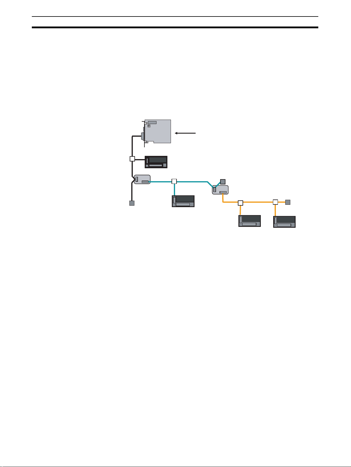
1-1 Overview of the CompoNet Network
CompoNet is a field network designed for communications between the input
and output components on the shop floor and a personal computer (or PC) or
a PLC. CompoNet requires less wiring labor but provides high maintainability.
The PC and the CompoNet Slave Unit exchange input and/or output data
cyclically through a CompoNet Master Board.
By using explicit messages, users can read data from the CompoNet Slave
Unit or write data into it.
High-Speed
Communications of
Multiple Nodes
Terminating
Resistor
Slave Unit
Repeater
Unit
Slave Unit
CompoNet Master Board
Terminating Resistor
Repeater Unit
Slave Unit
Terminating
Resistor
Slave Unit
Here are the main featur es of CompoNet:
CompoNet can provide remote I/O communications for multiple nodes as
many as maximum 2,560 points in a high speed such as 1000 points per
millisecond when the data rate is 4 Mbps*. This allows integration of
conventional system configuration with basic I/O Units into a CompoNet
network.
Greater Flexibility with
Repeater Units
2
* The data rate of 4 Mbps does not support T-branch connection. Thus any
Slave Unit with pre-attached cables is not usable.
Repeater Units can expand a network installation in the following ways:
• Extending the Communications cable,
• Increasing the number of connected nodes,
• Creating a branch connection from the trunk line, and
• Converting cable types.
Repeater Units can be used to expand the trunk line for up to two layers. The
lines downstream from the Repeater Units are called sub-trunk lines. The
maximum number of connectable Repeater Units is 64 per Master Board and
32 per trunk line.
Note The power to the sub-trunk lines must be supplied from the Repeater Units.
Page 23

Overview of the CompoNet Master Board Section 1-2
Bit-Level Distribution CompoNet is connectable with industry-standard e-CON connectors and
Slave Units of clamp terminal-block type. They allow bit-level controls of
conveyors or at warehouses where many sensors are placed over a wide
range.
Data Exchange by Explicit
Messages
Automatic Baud Rate
Detection
Explicit messages are used to access from the PC to the Slave Units and
Repeater Units connected to the CompoNet network. This feature facilitates
the maintenance of the entire networ k.
By setting the baud rate on the CompoNet Master Board, the Slave Units
automatically detect the baud rate of the CompoNet Master Board and follow
it. There is no need to set the rate individually on the Slave Units.
1-2 Overview of the CompoNet Master Board
CompoNet Master Board is a board that has a mastering function to control
inputs and outputs for the Slave Units connected to the CompoNet network.
The Board is either compatible with PCI bus (Model # 3G8F7-CRM21) or with
CompactPCI bus (Model # 3G8F8-CRM21).
Here are the main features of the CompoNet Master Board:
Control by API Functions In the Windows operation systems, all functions on the CompoNet Master
Board can be accessed by API functions.
Control by Shared
memory Accesses
In operation systems other than Windows, the CompoNet Master Board is
used via access to shared memory.
Flexible Allocation of the
Number of Connectable
Nodes
Registration Table
Function to Control
Participating Slave Units
Optimizing
Communications Cycle
Synchronous and
Asynchronous Access to
I/O Data
Other Functions • Communicat ions Stop Due to Communications Error function
The number of connectable nodes can be set differently for each Word Input
Slave Units, Word Output Slave Units, Bit Input Slave Units and Bit Output
Slave Units.
This function is used to pre-register the node addresses and models of Slave
Units that are to participate in the network, and to check whether a Slave Unit
that is actually participating is registered or not. If the Slave Unit is not
registered, it is not allowed to participate. The time can also be set to monitor
duration from power-on until a registered Slave Unit actually participates.
Remote I/O communications can be stopped until all registered Slave Units
participate in the network, but it can be started only with all Slave Units
participating. The latter function is called the All Registered Slave
Participation Standby Mode.
When the Registration Table function is used, the communications cycle is
optimized and fastened in accordance with the information in the table.
Both synchronous and asynchronous types of access are supported.
Synchronous access maintains synchronicity for each node, while
asynchronous access does not do that but instead provides faster access. In
the latter case, I/O data keeps synchronicity only within the same word.
• I/O Communications Manual Startup mode
• IN Data Zero Clear Due to Communications Error function
3
Page 24
Component Name and Function Section 1-3
1-3 Component Name and Function
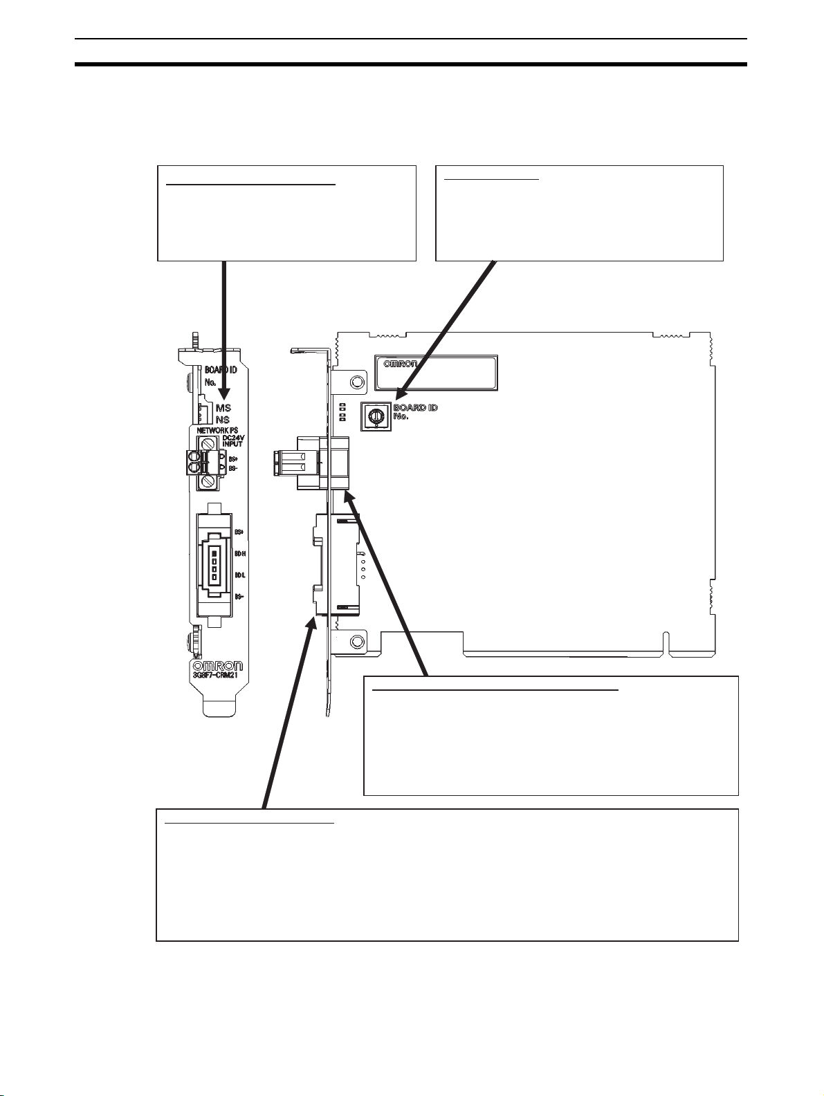
1-3-1 3G8F7-CRM21 (for PCI Bus)
LED Indicators (MS and NS)
They indicate the Module Status (MS)
and Network Status (NS) that are
defined in the CompoNet protocol.
Board ID Switch
This is used to set the board ID. It is set as a
decimal number. The number must not
overlap the IDs for other CompoNet Master
Boards mounted on the same personal
computer.
Communications power supply connector
This is used to connect a 24-VDC power supply when either
round cable II or Flat Cable I or II is used.
The communications power is supplied through this connector
and the round cable II, Flat Cable I or Flat Cable II to the Slave
Units and Repeater Units on the trunk line.
Note : Do not connect anything to this connector when a round
cable I is used.
Communications connector
This is used to connect to the communications cable.
The terminals BS+ and BS- are for communications power supply. The terminals BDH and BDL are for
communications data.
The BS+ and BS- can be used only for round cable II or Flat Cable I or II. They output the
communications power from the power supply connected to the communications power supply
connector.
Note : By attaching an Open Type Connector for Unit connection, the communications connector can be
converted to a terminal-block type.
4
Page 25
Component Name and Function Section 1-3
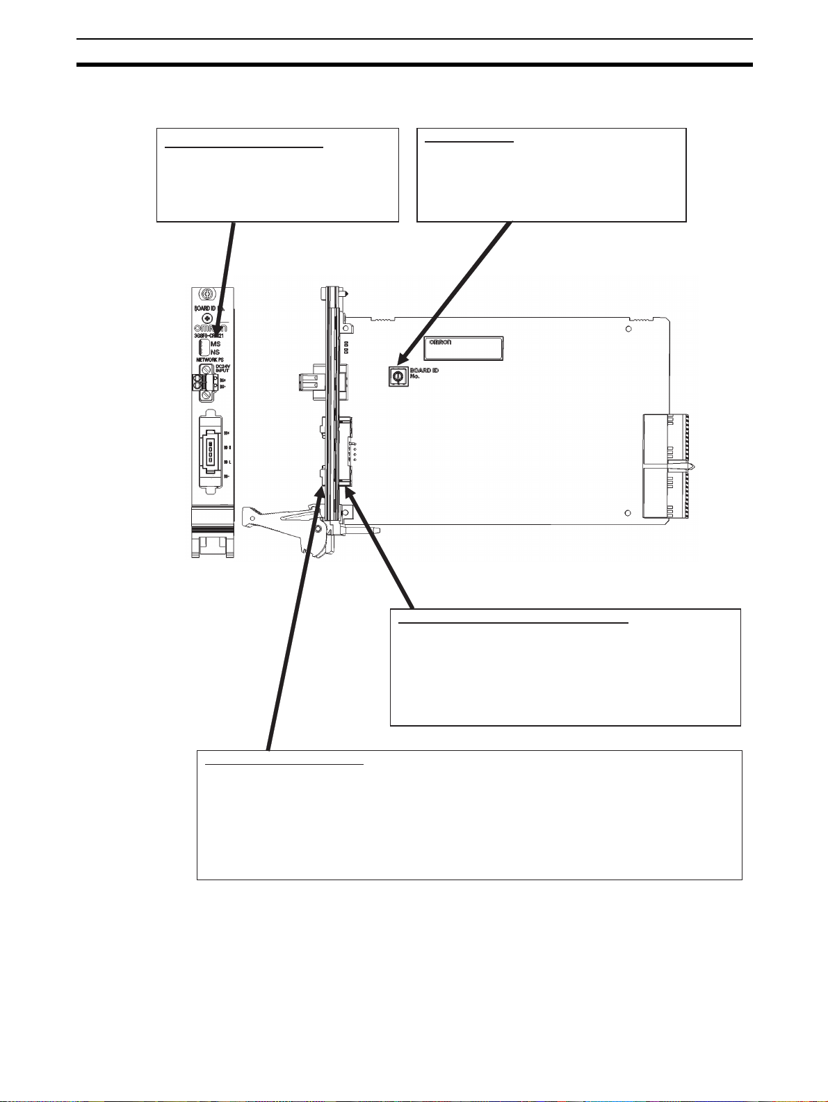
1-3-2 3G8F8-CRM21 (for CompactPCI Bus)
LED Indicators (MS and NS)
They indicate the Module Status (MS)
and Network Status (NS) that are
defined in the CompoNet protocol.
Board ID Switch
This is used to set the board ID. It is set as a
decimal number. The number must not
overlap the IDs for other CompoNet Master
Boards mounted on the same personal
computer.
Communications power supply connector
This is used to connect a 24-VDC power supply when either
round cable II or Flat Cable I or II is used.
The communications power is supplied through this connector
and the round cable II, Flat Cable I or Flat Cable II to the Slave
Units and Repeater Units on the trunk line.
Note : Do not connect anything to this connector when a round
cable I is used.
Communications connector
This is used to connect to the communications cable.
The terminals BS+ and BS- are for communications power supply. The terminals BDH and BDL are for
communications data.
The BS+ and BS- can be used only for round cable II or Flat Cable I or II. They output the
communications power from the power supply connected to the communications power supply
connector.
Note : By attaching an Open Type Connector for Unit connection, the communications connector can be
converted to a terminal-block type.
5
Page 26

LED Indication Section 1-4
1-4 LED Indication
MS (Module Status) : To indicate the node status. (green and red)
NS (Network Status) : To indicate the communications status. (green an d red)
LED Name Indicating state Status Meaning
MS Green light Normal state The Master Board is in normal operation.
Green flash Stand-by It waits for a start-up by the application.
Red light Fatal error Master Board hardware error (including Watchdog Timer
(WDT) error)
Red flash Non-fatal error EEPROM read error or PC WDT error
Unlit Power-off or in
preparation
NS Green light Online and in remote I/O
communications
Green flash Online and in
preparation for remote
I/O communications
Red light Fatal communication
related error
Red flash Non-fatal communication
related error
Unlit Power-off or in
preparation
One of the following applies:
Power is off.
The system is resetting or initializing.
All of the followings apply:
⋅ Power is supplied. Remote I/O communications starts up.
⋅ None of the Slave and Repeater Units has
communications error.
⋅ No Registration Table error exists.
⋅ None of the Slave and Repeater Units has node address
duplication.
It is before the remote I/O communications starts or during
communication. (In any state other than the communication
stop due to a communications error.)
The communications circuit has an error.
One of the following applies:
⋅ One or more Slaves or Repeater Units has a
communications error.
⋅ One or more Slaves or Repeater Units has a Registration
Table error. That means a Slave Unit to participate is not
participating or a non-registered Slave Unit is
participating.
⋅ The communications stops due to a communications
error.
⋅ Illegal configuration error (an error of Repeater levels)
⋅ One or more Slaves or Repeater Units had node address
duplications.
One of the following applies: Power is off. The system is
resetting or initializing.
Note The indicators flash in 0.5 second interval, i.e., they light for 0.5 second and
become unlit for another 0.5 second.
6
Page 27
Network Construction Procedure Section 1-5
1-5 Network Construction Procedure
The following is the basic flow of a network configuration.
1) Decide the number of I/O points.
Examine the number of inputs and outputs on the entire system.
2) Correspond the I/O points to Slave Units.
Assign each of these inputs and outputs to a Slave Unit.
3) Decide the number of nodes.
Decide the number of connected nodes.
4) Decide the wiring formation and installation.
Decide following:
• Wiring formation: Trunk line - Branch line formation or Unrestricted wiring
formation,
• Wiring distance,
• Methods to supply the communications power and the I/O power to the
Slave Units in less wiring effort, and
• Cable type
5) Temporarily decide the number of connectable Slave Units
and the data rate.
Note The data rate of 4 Mbps does not support T-branch. Thus any Slave Unit
with pre-attached cables will not be usable.
See Appendix E:
Construction of a
CompoNet Network
See E.1.3 Maximum
Length and Maximum
Number of Connectable
Slave Units for Each
Type of Cables
6) Decide the communications cycle.
Decide the communications cycle in accordance with the number of
connectable Slave Units and the data rate. Examine if the required I/O
response time is obtained in the data rate.
7) Examine the distribution of CompoNet Master Boards.
If re-examination of the communication mode number, the data rate and the
use of Repeater Units does not ensure the synchronicity of communication
cycle and distance, provide the CompoNet Master Boards in distributed
locations.
See Appendix C:
Communications
Performance
7
Page 28

Board Preparation Procedure Section 1-6
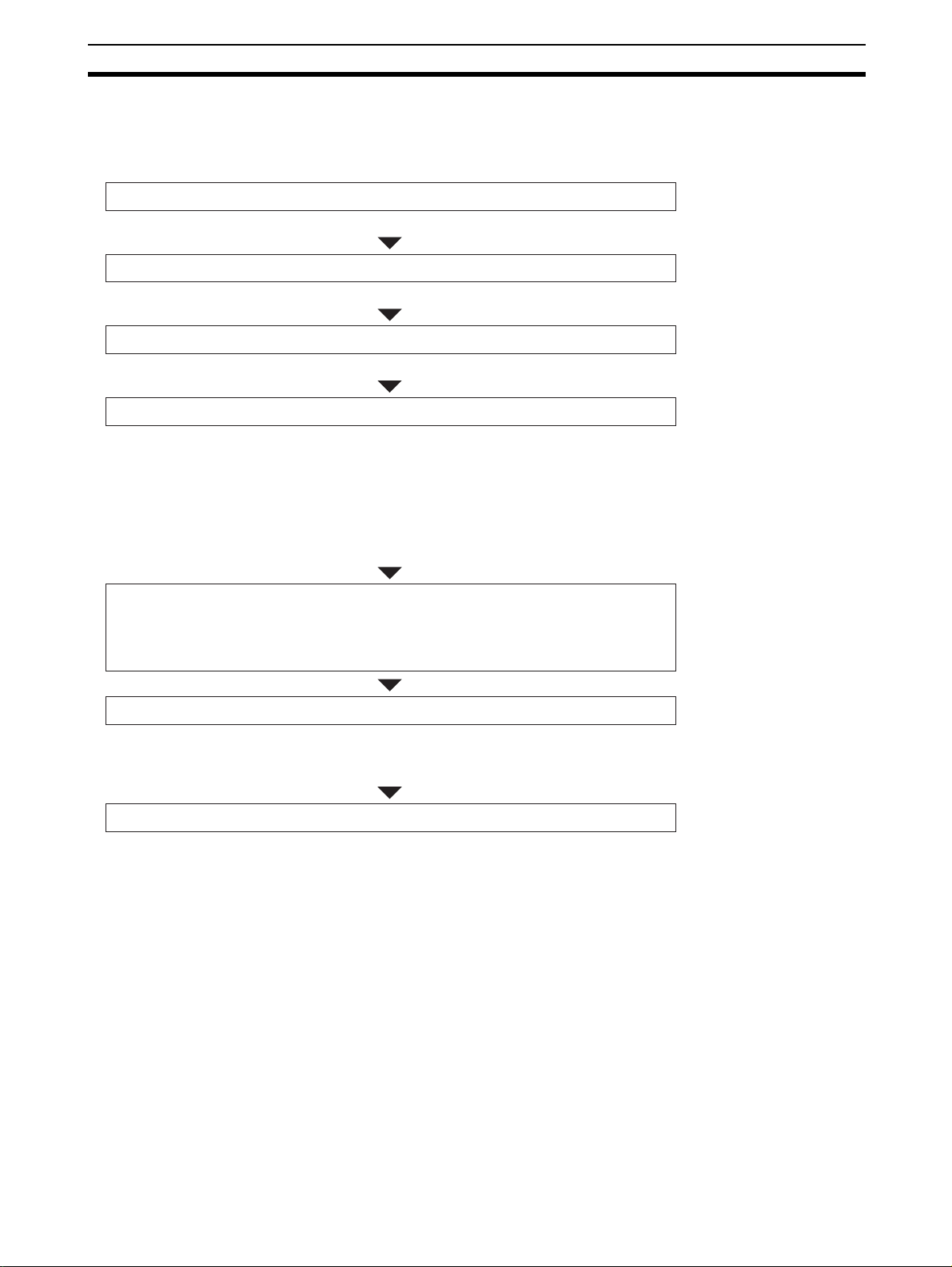
1-6 Board Preparation Procedure
The following is the basic flow of a Board preparation.
1) Set the board ID for the CompoNet Master Board.
Select one from 0 to 9.
2) Mount the Board on the PC.
Mount the CompoNet Master Board on the PC.
3) Install the software.
When you use the Board in the Windows operation systems, install the driver.
4) Create a program.
Create a program to configure and control the CompoNet Master Board.
5) Turn on the PC.
6) Start up the created program.
7) The communication starts and the Slave Units participate.
See Section 2:
Installation and
Setup
See Section 4:
Operation by API
Functions,
Section 5:
Operation by
Shared Memory
Access, and
Appendix D:
Sample Program
8
Page 29

Specifications Section 1-7
1-7 Specifications
1-7-1 General Specifications
Item Specifications
3G8F7-CRM21 (PCI) 3G8F8-CRM21
Bus specification PCI bus Rev2.2
5 V
Number of mountable
boards
Compatible OS Microsoft Windows 2000, Windows XP (32-bit edition),
Weight 90 g max. 150 g max.
Operation voltage
Consumption current Internal power supply: 5 VDC and 1.5 A max
Vibration resistance 10 to 57 Hz, Amplitude of 0.075 mm, 57 to 150 Hz
Shock resistance
Ambient operating
temperature
Ambient operating
humidity
Ambient operating
atmosphere
Storage temperature
4 pieces 7 pieces
Windows Vista (32-bit edition), or Windows 7 (32-bit
edition)
Other OS can be used, when the shared memory interface
is directly accessed.
Internal power supply: 5 VDC
3.3 VDC is not used.
Communications power supply: 24 VDC and 80 mA max
2
Acceleration 9.8 m/s
Z (8 min of each sweep time × 10 sweeps = total 80 min)
147 m/s2, 3 times each in X, Y and Z directions.
0 to 55°C
0% to 80% RH (with no
condensation)
No corrosive gas
-20 to +60
°C
, 80 min in each direction of X, Y and
(CompactPCI)
PICMG 2.0 R3.0
5 V
32-Bit 3U
±5%
0% to 90% RH (with no
condensation)
Precautions for Correct Use
The ambient operating temperature means the surrounding temperature
where the CompoNet Master Board for PCI Bus is actually used.
See the PC operation manual for the appropriate ambient operating
temperature for the PC.
1-7-2 Development Environment
• Microsoft Visual C++ (Ver 6.0 to Ver 2008)
• Microsoft Visual Basic (Ver 6.0)
• CODEGEAR C++ Builder (Ver 5 to V er 2009)
Precautions for Correct Use
When you use the Board in an OS other than Windows by directly accessing
the shared memory interface, provide the development environment
applicable for the OS.
9
Page 30
Specifications Section 1-7
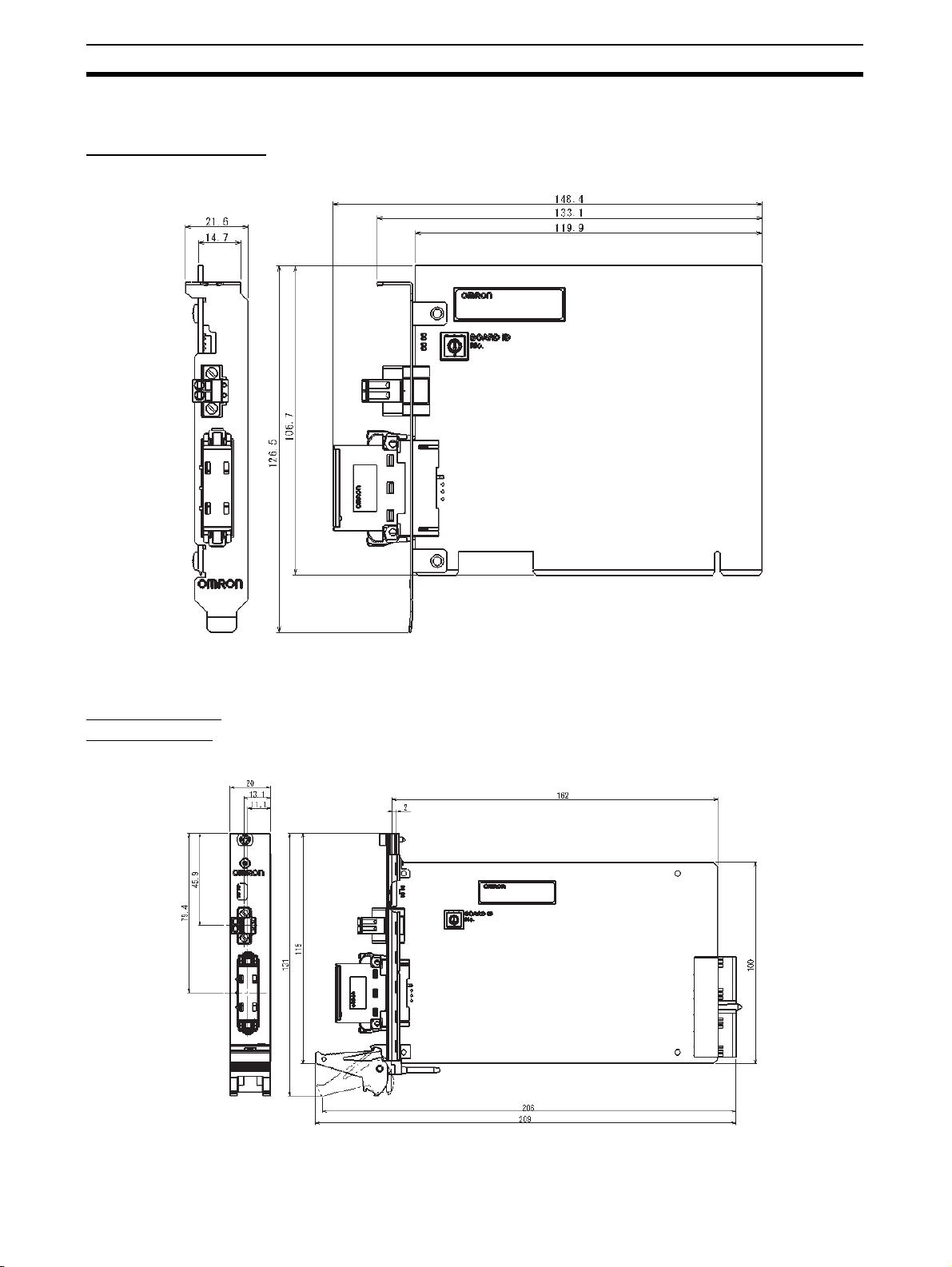
1-7-3 Dimensions
3G8F7-CRM21 (PCI)
3G8F8-CRM21
(CompactPCI)
(unit: mm)
10
(unit: mm)
Page 31

Installation and Setup
2-1 Mounting a Board . . . . . . . . . . . . . . . . . . . . . . . . . . . . . . . . . . . . . . . . . . . . . . 12
2-1-1 Confirmation . . . . . . . . . . . . . . . . . . . . . . . . . . . . . . . . . . . . . . . . . . . 12
2-1-2 Setting the Board ID . . . . . . . . . . . . . . . . . . . . . . . . . . . . . . . . . . . . . 12
2-1-3 Mounting the Board on the PC . . . . . . . . . . . . . . . . . . . . . . . . . . . . . 13
2-2 Installing the Drivers . . . . . . . . . . . . . . . . . . . . . . . . . . . . . . . . . . . . . . . . . . . . 14
2-3 Connecting the Communications Cables. . . . . . . . . . . . . . . . . . . . . . . . . . . . . 21
2-3-1 Connecting a Round Cable . . . . . . . . . . . . . . . . . . . . . . . . . . . . . . . . 21
2-3-2 Connecting a Flat Cable . . . . . . . . . . . . . . . . . . . . . . . . . . . . . . . . . . 23
2-4 Connecting the Communications Power Supply Cables . . . . . . . . . . . . . . . . . 25
SECTION 2
11
Page 32

Mounting a Board Section 2-1
2-1 Mounting a Board
2-1-1 Confirmation
Before you mount a CompoNet Master Board on the PC, confirm the
following:
Note CompoNet Master Boards support Windows Plug & Play.
Item Description
Unused PCI bus slot Be sure that the PC you will use has an unused PCI bus slot.
Duplication of
interrupt requests
(IRQ)
CompoNet Master Boards use IRQs. IRQ are automatically
allocated for PCI bus. In a PC which mounts an ISA bus, an
IRQ for PCI bus may overlaps with that for ISA bus. This
prevents the PC from starting up. To avoid this, take one of the
following measures and be sure the IRQ for PCI bus does not
overlap with the IRQ that has been used by the ISA bus.
⋅ Call up the BIOS menu of the PC and set it not to use Plug &
Play.
⋅ Call up the BIOS menu of the PC, and on the setting step for
IRQ allocation for the PCI bus set the IRQ that has been
used by ISA bus to “Reserved” to prevent automatic
allocation.
Note
• As for the procedures to call the BIOS menu and to set the allocation, see
the operation manual of the PC you are using.
• You can confirm the IRQs that have been used by ISA bus in the following
procedure:
(1) Start up the PC that has no CompoNet Master Board mounted.
(2) On the Star t menu of the Windows, select Start
from the pop-up menu. Doub le-clic k the System. Select the Hardw are Tab.
Push the Device Manager button.
(3) D isplay the property of the ISA board whose IRQ is to be checked. Select
the Resource Tab and check the IRQ.
2-1-2 Setting the Board ID
A Board ID is the ID number given to a Board. By this number the PC
identifies a Board among the multiple CompoNet Master Boards mounted on
it.
0
1
9
2
8
3
7
4
6
5
→Setting→Control Panel
12
A small, flat-blade screwdriver is used to set IDs.
As long as no duplication occurs, any decimal number among 0 and 9 can be
set.
Precautions for Correct Use
When you set the Board ID, be sure not to duplicate an ID for multiple
CompoNet Master Boards mounted on a single PC.
Page 33

Mounting a Board Section 2-1
Note In the factory setting, the Board ID is set to 0.
2-1-3 Mounting the Board on the PC
After setting the ID, mount the CompoNet Master Board on the PCI slot of the
PC.
Precautions for Correct Use
•Be sure to turn off the PC and all peripheral devices, when you mount or
remove a CompoNet Master Board.
•Take necessary measures to prevent static electricity before you start the
procedures to mount a CompoNet Master Board. Otherwise, the electricity
may break the Board or the PC.
•Be sure not to damage any memories or other components in the PC, when
you work on mounting or removing a CompoNet Master Board.
•Do not touch any surface or components of the CompoNet Master Board by
hand.
Note The procedure to mount a Board for PCI bus differs by PCs. Refer to the
Operation Manual of the PC you use in order to follow the correct procedures.
Follow the mounting procedure given below:
1. Disconnect all cables from the CompoNet Master Board. Thi s includes the
communications cables and power supply cables.
2. Turn off the PC to which a Board is mounted. Disconnect the electrical
cord.
3. Remove the pac kage of the PC as instructed in the Oper ation Manual, and
prepare it to mount or remove a CompoNet Master Board.
4. Place the PCI bus connecter on the PC and the connector on the
CompoNet Master Board in the correct positions and orientations. Push
the CompoNet Master Board t o the end. Be sure the connector on the
CompoNet Master Board is pushed evenly onto the connector on the PC.
5. Do not apply an excessive load to the Board while mounting it.
6. Pull the CompoNet Master Board lightly to confirm that it won't come out.
7. Tighten the screws on the left side of the CompoN et Master Board panel
with 0.5 N⋅m torque, and secure the Board.
13
Page 34

Installing the Drivers Section 2-2
2-2 Installing the Drivers
If you are using Windows 2000, Windows XP, Windows Vista, or Windows 7,
use the Add New Hardware Wizard provided by the OS to install the
CompoNet Master Board driver.
Procedures are provided here for Windows 2000 and Windows 7. When you
use Windows XP or WindowsVista, displays and procedures differ only
slightly, but you can take the similar steps.
Windows 2000
Note To perform the following installation steps, you must log on as the
Administrator.
1,2,3... 1. Start up the PC after you mount a CompoNet Master Board on the PC.
The PC will recognizes the Board as a new hardware. The Found New
Hardware Wizard will starts up.
Click the Next button.
14
Page 35

Installing the Drivers Section 2-2
2. On the wizard page of Install Har d ware Device Driver s, select the bu tton
for Search for suitable driver for my device (recommended). Click the
Next button.
3. On the wizard page of Locate Driver Files, check the box for CD-ROM
drive. Click the Next button.
(Be sure to insert the attached CD-ROM before you select the drive.)
15
Page 36

Installing the Drivers Section 2-2
4. When the required driver file is found, click the Next button.
5. The installation is complete when the following page is shown and the
Finish button is clicked.
16
Page 37

Installing the Drivers Section 2-2
Windows 7
Note For Windows 7, you must log as the administrator to install the driver.
1,2,3... 1. After the Board is installed in the computer, start the Device Manager. Ne w
*1
hardware will be detected automatically. Open the Device Manager,
double-click Other devices.
*1.To open the Device Manager, click the Windows Start Button and select Control
Panel, Hardware and Sound, and Device Manager in that order.
and
2. The Network Contr oller will appear under Other devices.
Right-click Network Controller and then select Update Driver Software
from the menu.
17
Page 38

Installing the Drivers Section 2-2
3. How do you want to search for driver software? will be displayed.
Click Browse my computer for driver software.
4. Place the enclosed CD-ROM into the CD-ROM drive.
5. Browse for driver software on your computer will be displayed.
Click the Browse Button, sp ecify the CD-R OM drive (see follo wing figure),
and click the Next Button
*. The foll owing figure shows an example for which drive D is the CD-ROM drive.
18
Page 39

Installing the Drivers Section 2-2
6. The following dialog box will be displayed. Click Install this driver
software anywa y to start installation.
7. The installation will start.
19
Page 40

Installing the Drivers Section 2-2
8. A completion message (see the following figure) is displayed after the
installation process is completed.
Click the Close Button to complete driv er installation.
20
Page 41

Connecting the Communications Cables Section 2-3
2-3 Connecting the Communications Cables
This section outlines the connection procedures in a CompoNet network
system by using a round cable I or Flat Cable I.
2-3-1 Connecting a Round Cable
An Open Type Connector (DCN4-TB4) is used to connect a CompoNet
Master Board to the trunk line of either round cable I or II.
Align the terminal signals of the Connector. Press in the Connector until it
clicks into place.
Note To remove the inserted Connector, hold the latches on both sides and pull out
the Connector.
21
Page 42

Connecting the Communications Cables Section 2-3
CRT1
OD16
CRT1
OD16
Precautions for Correct Use
Please be aware that the wiring of the Open Type Connector (DCN4-TB4) will
protrude into the adjacent panel. Provide any measures to prevent it from
interfering with the connector and other component of the neighboring PCI
Board.
Example of round
cable I connection
DCN4-TB4 Open Type Connector
DCN4-TB4 Open Type Connector
MS
NS
WORD
NODE ADR
01234567 8
5
6
4
7
5
6
9
10 11
12
13
14
OUT
X1
15
MS
REMOTE
NS
WORD
NODE ADR
01234567 8
5
6
4
7
5
6
9
CRT1
TERMINAL
4
7
3
8
3
8
2
9
1
2
9
0
1
0
X10
[0
-
63]
-
OD16
-
1
10 11
12
13
14
OUT
X1
15
ANALOG
MS
CRT1
TERMINAL
NS
WORD
NODE ADR
5
6
4
12345678
7
5
6
4
7
3
8
3
8
2
9
1
2
0
9
1
0
X10
X1
[0
-
63]
-
AD04
A
/
D
SW
ON
1
INPUT
2
RANGE
CH0,1
3
4
INPUT
5
RANGE
CH2,3
6
7
RSV
8
LSET
REMOTE
CRT1
TERMINAL
4
7
3
8
3
8
2
9
1
2
9
0
1
0
X10
[0
-
63]
-
OD16
-
1
Word Slave Unit
DRS1-T Terminating Resistor
Note A commercially available relay terminal block can make a T-branching
connection.
22
Page 43

Connecting the Communications Cables Section 2-3
2-3-2 Connecting a Flat Cable
A Flat Connector Plug (DCN4-BR4 or DCN5-BR4) is used to connect a
CompoNet Master Board to the trunk line of either Flat Cable I or II. A Flat
Connector I Plug (DCN4-BR4) is used with Flat Cable I, while a Flat
Connector II Plug (DCN5-BR4) is used with Flat Cable II.
Flat Connector I Plug (DCN4-BR4) Flat Connector II Plug (DCN5-BR4)
Align the Plug face with the color seals (red, white, blue and black) matching
the signal names (red and BS+) on the connector. Press the plug until it clicks
into place.
Note To remove the inserted Plug, hold the latches on both sides and pull out the
Plug
.
23
Page 44

Connecting the Communications Cables Section 2-3
OD16
Precautions for Correct Use
•Please be aware that the Multidrop Connector (DCN4-MD4) will protrude into
the adjacent panel. Provide any measures to prevent it from interfering with
the connector and other component of the neighboring PCI Board.
•In a configuration where plural 3G8F7-CRM21 CompoNet Master Boards for
PCI Bus are used, only one side of adjacent two Boards shall use a DCN4 MD4 Multidrop Connector.
Example of T-branch
connection of Flat
Cable I
DCN4-BR4 Flat Connector Plug
DCN4-TR4 Flat Connector Socket
T-branch
DCN4-BR4 Flat Connector
Plug
DCN4-BR4 Flat Connector Plug
MS
NS
WORD
NODE ADR
01234567 8
5
6
7
4
5
6
7
4
3
8
3
8
2
9
1
OUT
2
9
0
1
0
X10
X1
[0
-
63]
CRT1
-
OD16
-
REMOTE
1
TERMINAL
Word Slave Unit
DCN4-TR4 Flat Connector Socket DCN4-TR4 Flat Connector Socket
T-branch
DCN4-BR4 Flat Connector
DCN4-TM4 Terminating Resistor
Plug
9
10 11
12
13
14
15
Bit Slave Unit
24
Page 45

Connecting the Communications Power Supply Cables Section 2-4
CR
T1
OD16
CR
T1
Example of multidrop
connection of Flat
Cable I
DCN4-BR4 Flat Connector Plug
DCN4-MD4 Multidrop Connector
DCN4-TM4 T erminating Resistor
MS
NS
WORD
NODE ADR
01234567
5
6
7
4
5
6
8
9
4
7
3
8
3
8
2
9
1
2
9
0
1
0
X10
X1
[0
-
63]
CR
T1
-
OD16
-
REMOTE
1
TERMINAL
10 11
12
13
14
OUT
15
MS
NS
WORD
NODE ADR
0 123 4567 8
5
6
4
7
5
6
9
4
7
3
8
3
8
2
9
1
2
9
0
1
0
X10
[0
-
63]
CR
T1
-
OD16
-
REMOTE
1
TERMINAL
10 11
12
13
14
OUT
X1
15
ANALOG
MS
CRT1
TERMINAL
NS
WORD
NODE ADR
5
6
4
12345678
7
5
6
4
7
3
8
3
8
2
9
1
2
0
9
1
0
X10
X1
[0
-
63]
-
AD04
A
/
D
SW
1
ON
INPUT
2
RANGE
CH0,1
3
4
INPUT
5
RANGE
CH2,3
6
7
RSV
8
LSET
Word Slave Unit
2-4 Connecting the Communications Power Supply Cables
When a round cable II, Flat Cable I or Flat Cable II is used, the Slave Units
can be supplied with the communications power through the CompoNet
Master Board. In this case, the communications power supply must be
connected to the CompoNet Master Board.
See Appendix E.5 Wiring for Power Supply, especially E.5.2 Wiring the
Communications Po wer Supply.
25
Page 46

Connecting the Communications Power Supply Cables Section 2-4
26
Page 47

3-1 Settings at Communications Cycle Startup . . . . . . . . . . . . . . . . . . . . . . . . . . . 28
3-1-1 Settings Required for Starting the Communicat ion s Cycl e . . . . . . . 28
3-2 Access to I/O Data. . . . . . . . . . . . . . . . . . . . . . . . . . . . . . . . . . . . . . . . . . . . . . 30
3-2-1 Allocation of I/O Data. . . . . . . . . . . . . . . . . . . . . . . . . . . . . . . . . . . . 30
3-2-2 Access to I/O Data. . . . . . . . . . . . . . . . . . . . . . . . . . . . . . . . . . . . . . . 35
3-3 Status . . . . . . . . . . . . . . . . . . . . . . . . . . . . . . . . . . . . . . . . . . . . . . . . . . . . . . . . 35
3-3-1 Basic Status Group . . . . . . . . . . . . . . . . . . . . . . . . . . . . . . . . . . . . . . 35
3-3-2 Detailed Status Group . . . . . . . . . . . . . . . . . . . . . . . . . . . . . . . . . . . . 36
3-4 Explicit Messages . . . . . . . . . . . . . . . . . . . . . . . . . . . . . . . . . . . . . . . . . . . . . . 37
3-5 Detailed Settings at Communications Cycle Startup. . . . . . . . . . . . . . . . . . . . 37
3-5-1 Registration Table Function . . . . . . . . . . . . . . . . . . . . . . . . . . . . . . . 37
3-5-2 Communications Stop Due to Communications Error Function . . . 39
3-5-3 I/O Commun icati ons Manual Startup Function . . . . . . . . . . . . . . . . 39
3-5-4 IN Data Zero Clear Due to Communications Error Function. . . . . . 40
SECTION 3
Functions
27
Page 48

Settings at Communications Cycle Startup Section 3-1
3-1 Settings at Communications Cycle Startup
The function CPNT_StartCycle is used to start the communications cycles for
the CompoNet Master Board from the user application. The function
CPNT_StartCycle uses the data rate and the number of occupied nodes as
arguments.
The command OPEN_SYSTEM is used to start the communications cycles
through the shared memory access.
To enable the superior function and start the communications cycle, execute
the function CPNT_StartCycleEx in Windows or the command
OPEN_SYSTEMEX for shared memory access. See Section 3-5.
3-1-1 Settings Required for Starting the Communications Cycle
Function Description
Data rate This is used to set the data rate for a network.
The Slave Units in the same network automatically follow the
data rate of the Master Board.
Data rate is selective among 4 Mbps, 3 Mbps, 1.5 Mbps and
93.75 kbps.
Number of occupied
nodes
The number of nodes can be set individually for Word IN Slave
Units, Word OUT Slave Units, Bit IN Slave Units and Bit OUT
Slave Units.
*1.Every 16 points of a Word IN Slave Unit or a Word OUT
Slave Unit occupies 1 node.
*2.Every 2 points of a Bit IN Slave Unit or a Bit OUT Slave Unit
occupies 1 node.
*3.Node addresses are allocated to Slave Units in ascending
order starting from #0. Unused addresses are also included
in this allocation order. They cannot be skipped.
*4.Only the Slave Units in this set range are to participate. Not
all of the occupied areas are necessarily allocated by a
Slave Unit.
Example: When a system consists of Slave Units as shown in
the table below , the number of nodes occupied by each type of
Slave Units are:
8 by Word IN Slave Units,
3 by Word OUT Slave Unit, (*3)
3 by Bit IN Slave Unit,
10 by Bit OUT Slave Units (*3)
Slave type
Word IN Slave Unit 16
Word IN Slave Unit 32
Word IN Slave Unit 16
Word IN Slave Unit 64
Word OUT Slave Unit 32
Bit IN Slave Unit 4
Bit IN Slave Unit 2
Bit OUT Slave Unit 2
Bit OUT Slave Unit 2
Node
address
0
1
3
4
1
0
2
0
9
# of points Remarks
(*1)
(*1)
(*1)
(*2)
28
Page 49

Settings at Communications Cycle Startup Section 3-1
Note • Ev ery 16 points of a W ord IN Slave Unit or a Word OUT Slave Un it occupi es
1 node. For example, when a Word Slav e Unit has 64 point s and is allocated
with the node address #10, it actually occupies the node address #10, #11
#12 and #13.
• Every 2 points of a Bit IN Slave Unit or a Bit OUT Slave Unit occupies 1
node. For example, when a Bit Slave Unit has 4 points and is allocated with
the node address #5, it actually occupies the node address #5 and #6.
Image of the number of nodes occupied by the above Slave Units
Allocation of Word IN Slave Units
Node address
0
Used by Word IN Slave Unit with node address 0.
1
Used by Word IN Slave Unit with node address 1.
2
3
Used by Word IN Slave Unit with node address 3.
4
Used by Word IN Slave Unit with node address 4.
5
6
7
The number
of occupied
nodes is 8.
Allocation of Word OUT Slave Units
Node address
0
Unused
1
Used by Word OUT Slave Unit node address 1.
2
Allocation of Bit IN Slave Units
Node address
Used by Bit IN Slave Unit node address 0.
0
1
Used by Bit IN Slave Unit node address 2.
2
Allocation of Bit OUT Slave Units
Node address
0
Used by Bit OUT Slave Unit node address 0.
1 to 8
Unused
9
Used by Bit OUT Slave Unit node address 9.
The number
of occupied
nodes is 3.
The number
of occupied
nodes is 3.
The number
of occupied
nodes is 10.
29
Page 50

Access to I/O Data Section 3-2
3-2 Access to I/O Data
3-2-1 Allocation of I/O Data
In the CompoNet network system, the I/O data is allocated separately for
Word IN Slave Units, Word OUT Slave Units, Bit IN Slave Units, and Bit OUT
Slave Units. It is allocated in the shared memory of the CompoNet Master
Board.
Allocation for W ord IN
Slave Units and Word
OUT Slave Units
• Every 16 points of a Word IN Slave Unit or a Word OUT Slave Unit
occupies 1 word in allocation area. For example, a 32-point IN Slave Unit
occupies 2 words in allocation area for Word IN Slave Units.
• The offset address that is allocated to the shared memo ry is deter mined
by the node address.
• Word MIX Slave Units occupy the allocation areas for both of Word IN
Slave Units and Word OUT Slave Units. For example, when a Word MIX
Slave Units has 16 inputs and 64 outputs, it occupies 1 word in the
allocation area for Word IN Slave Units and 4 words in the allocation area
for Word OUT Slave Units.
• An 8-point Slave Unit also occupies 1 node or 1 word. It is allocated to the
lower byte of the 1- word, while the upper byte remains open.
Allocation area for IN Data of a Word IN Slave Unit
Word address Bit 15 Bit 0
+0 [IN data of Word IN Slave Unit with node address 0]
+1 [IN data of Word IN Slave Unit with node address 1]
IN
area
+2 [IN data of Word IN Slave Unit with node address 2]
::
+62 [IN data of Word IN Slave Unit with node address 62]
+63 [IN data of Word IN Slave Unit with node address 63]
30
Allocation area for OUT Data of a Word OUT Slave Unit
Word address Bit 15 Bit 0
+0 [OUT data of Word OUT Slave Unit with node address 0]
+1 [OUT data of Word OUT Slave Unit with node address 1]
OUT
area
Note A single allocation area shall never be occupied by plural nodes. However, as
long as the same words are not allocated to more than one Unit, the Input
Area and Output Area with numerically the same node address can be
allocated to Slave Units with different node addresses. For example, OUT1
can be allocated to the 16 outputs for a Word OUT Slave Unit set for node
address 1, and IN1can be allocated to the 16 inputs for a Word IN Slave Unit
set for node address 1.
+2 [OUT data of Word OUT Slave Unit with node address 2]
: :
+62 [OUT data of Word OUT Slave Unit with node address 62]
+63 [OUT data of Word OUT Slave Unit with node address 63]
Page 51

Access to I/O Data Section 3-2
Precautions for Correct Use
When a Slave Unit occupies plural allocation areas, other Slave Units which
have the occup ied node addresses cannot participate.
Example: When a Slave Unit with node address 0 exists in a network and it
occupies 2 words in the IN area and 4 words in OUT area, Word IN
Slave Units whose node addr esses are 0 or 1, a nd Word OUT Slave
Units whose node addresses are 0, 1, 2 or 3 cannot participate.
Image of the above Precautions for Correct Use
Allocation area for IN Data of a Word IN Slave Unit
Word address Bit 15 Bit 0
+0 [IN data of Word MIX Slave Unit with node address 0]
+1
+2
IN
area
+3
+4
:
+62
+63
Allocation area for OUT Data of a Word OUT Slave Unit
Word address Bit 15 Bit 0
+0
[OUT data of Word MIX Slave Unit with node address 0]
OUT
area
+1
+2
+3
+4
:
+62
+63
Data allocation
• 8-Point Word IN Slave Unit
IN area
Unused
• 8-Point Word OUT Slave Unit
OUT area
Unused
12345670
12345670
31
Page 52

Access to I/O Data Section 3-2
• 16-Point Word IN Slave Unit
IN area
123456789101112131415 0
• 16-Point Word OUT Slave Unit
OUT area
123456789101112131415 0
• 32-Point Word IN Slave Unit
IN area
123456789101112131415 0
171819202122232425262728293031 16
• 32-Point Word OUT Slave Unit
Allocation for Bit IN
Slave Units and Bit
OUT Slave Units
OUT area
123456789101112131415 0
171819202122232425262728293031 16
• 16-Input and 16-Output Word MIX Slave Unit
OUT area
123456789101112131415 0
IN area
123456789101112131415 0
Every Bit Slave Unit occupies 2 point or 2 bits.
For example, 8 sets of 2-point Slave Units occupy 1 word. In the same
manner, a combination of 4 sets of 2-point Slave Units, and 2 sets of 4-point
Slave Units, occupies 1 word.
A 2-point Slave Unit occupies 2 bits as a node, which is for its own node
address.
A 4-point Slave Unit occupies 4 bits as a node, which is for its own and for the
next node addresses.
32
Page 53

Access to I/O Data Section 3-2
BIT IN Data Allocation Area
Bit
15 14 13 12 11 10 9 8 7 6 5 4 3 2 1 0
[BIT IN 7]
[BIT IN 15]
[BIT IN 23]
[BIT IN 31]
[BIT IN 39]
[BIT IN 47]
[BIT IN 55]
[BIT IN 63]
[BIT IN 71]
[BIT IN 79]
[BIT IN 87]
[BIT IN 95]
[BIT IN 103]
[BIT IN 111]
[BIT IN 119]
[BIT IN 127]
[BIT IN 6]
[BIT IN 14]
[BIT IN 22]
[BIT IN 30]
[BIT IN 38]
[BIT IN 46]
[BIT IN 54]
[BIT IN 62]
[BIT IN 70]
[BIT IN 78]
[BIT IN 86]
[BIT IN 94]
[BIT IN 102]
[BIT IN 110]
[BIT IN 118]
[BIT IN 126]
[BIT IN 5]
[BIT IN 13]
[BIT IN 21]
[BIT IN 29]
[BIT IN 37]
[BIT IN 45]
[BIT IN 53]
[BIT IN 61]
[BIT IN 69]
[BIT IN 77]
[BIT IN 85]
[BIT IN 93]
[BIT IN 101]
[BIT IN 109]
[BIT IN 117]
[BIT IN 125]
[BIT IN 4]
[BIT IN 12]
[BIT IN 20]
[BIT IN 28]
[BIT IN 36]
[BIT IN 44]
[BIT IN 52]
[BIT IN 60]
[BIT IN 68]
[BIT IN 76]
[BIT IN 84]
[BIT IN 92]
[BIT IN 100]
[BIT IN 108]
[BIT IN 116]
[BIT IN 124]
[BIT IN 3]
[BIT IN 11]
[BIT IN 19]
[BIT IN 27]
[BIT IN 35]
[BIT IN 43]
[BIT IN 51]
[BIT IN 59]
[BIT IN 67]
[BIT IN 75]
[BIT IN 83]
[BIT IN 91]
[BIT IN 99]
[BIT IN 107]
[BIT IN 115]
[BIT IN 123]
[BIT IN 2]
[BIT IN 10]
[BIT IN 18]
[BIT IN 26]
[BIT IN 34]
[BIT IN 42]
[BIT IN 50]
[BIT IN 58]
[BIT IN 66]
[BIT IN 74]
[BIT IN 82]
[BIT IN 90]
[BIT IN 98]
[BIT IN 106]
[BIT IN 114]
[BIT IN 122]
[BIT IN 1]
[BIT IN 9]
[BIT IN 17]
[BIT IN 25]
[BIT IN 33]
[BIT IN 41]
[BIT IN 49]
[BIT IN 57]
[BIT IN 65]
[BIT IN 73]
[BIT IN 81]
[BIT IN 89]
[BIT IN 97]
[BIT IN 105]
[BIT IN 113]
[BIT IN 121]
[BIT IN 0]
[BIT IN 8]
[BIT IN 16]
[BIT IN 24]
[BIT IN 32]
[BIT IN 40]
[BIT IN 48]
[BIT IN 56]
[BIT IN 64]
[BIT IN 72]
[BIT IN 80]
[BIT IN 88]
[BIT IN 96]
[BIT IN 104]
[BIT IN 112]
[BIT IN 120]
IN
area
Word
address
+0
+1
+2
+3
+4
+5
+6
+7
+8
+9
+10
+11
+12
+13
+14
+15
OUT
area
Word
address
+0
+1
+2
+3
+4
+5
+6
+7
+8
+9
+10
+11
+12
+13
+14
+15
BIT OUT Data Allocation Area
Bit
15 14 13 12 11 10 9 8 7 6 5 4 3 2 1 0
[BIT OUT 7]
[BIT OUT 15]
[BIT OUT 23]
[BIT OUT 31]
[BIT OUT 39]
[BIT OUT 47]
[BIT OUT 55]
[BIT OUT 63]
[BIT OUT 71]
[BIT OUT 79]
[BIT OUT 87]
[BIT OUT 95]
[BIT OUT 103]
[BIT OUT 111]
[BIT OUT 119]
[BIT OUT 127]
[BIT OUT 6]
[BIT OUT 14]
[BIT OUT 22]
[BIT OUT 30]
[BIT OUT 38]
[BIT OUT 46]
[BIT OUT 54]
[BIT OUT 62]
[BIT OUT 70]
[BIT OUT 78]
[BIT OUT 86]
[BIT OUT 94]
[BIT OUT 102]
[BIT OUT 110]
[BIT OUT 118]
[BIT OUT 126]
[BIT OUT 5]
[BIT OUT 13]
[BIT OUT 21]
[BIT OUT 29]
[BIT OUT 37]
[BIT OUT 45]
[BIT OUT 53]
[BIT OUT 61]
[BIT OUT 69]
[BIT OUT 77]
[BIT OUT 85]
[BIT OUT 93]
[BIT OUT 101]
[BIT OUT 109]
[BIT OUT 117]
[BIT OUT 125]
[BIT OUT 4]
[BIT OUT 12]
[BIT OUT 20]
[BIT OUT 28]
[BIT OUT 36]
[BIT OUT 44]
[BIT OUT 52]
[BIT OUT 60]
[BIT OUT 68]
[BIT OUT 76]
[BIT OUT 84]
[BIT OUT 92]
[BIT OUT 100]
[BIT OUT 108]
[BIT OUT 116]
[BIT OUT 124]
[BIT OUT 3]
[BIT OUT 11]
[BIT OUT 19]
[BIT OUT 27]
[BIT OUT 35]
[BIT OUT 43]
[BIT OUT 51]
[BIT OUT 59]
[BIT OUT 67]
[BIT OUT 75]
[BIT OUT 83]
[BIT OUT 91]
[BIT OUT 99]
[BIT OUT 107]
[BIT OUT 115]
[BIT OUT 123]
[BIT OUT 2]
[BIT OUT 10]
[BIT OUT 18]
[BIT OUT 26]
[BIT OUT 34]
[BIT OUT 42]
[BIT OUT 50]
[BIT OUT 58]
[BIT OUT 66]
[BIT OUT 74]
[BIT OUT 82]
[BIT OUT 90]
[BIT OUT 98]
[BIT OUT 106]
[BIT OUT 114]
[BIT OUT 122]
[BIT OUT 1]
[BIT OUT 9]
[BIT OUT 17]
[BIT OUT 25]
[BIT OUT 33]
[BIT OUT 41]
[BIT OUT 49]
[BIT OUT 57]
[BIT OUT 65]
[BIT OUT 73]
[BIT OUT 81]
[BIT OUT 89]
[BIT OUT 97]
[BIT OUT 105]
[BIT OUT 113]
[BIT OUT 121]
[BIT OUT 0]
[BIT OUT 8]
[BIT OUT 16]
[BIT OUT 24]
[BIT OUT 32]
[BIT OUT 40]
[BIT OUT 48]
[BIT OUT 56]
[BIT OUT 64]
[BIT OUT 72]
[BIT OUT 80]
[BIT OUT 88]
[BIT OUT 96]
[BIT OUT 104]
[BIT OUT 112]
[BIT OUT 120]
Note A single allocation area shall never be occupied by plural nodes. However, as
long as the same words are not allocated to more than one Unit, the Bit Input
Area and Bit Output Area with numerically the same node address can be
allocated to Slave Units with different node addresses. For example, BIT
OUT1 area can be allocated to the 2 out puts for a Bit Output Slave Unit set for
node address 1, and BIT IN1 can be allocated to the 2 inputs for a Bit Input
Slave Unit set for node address 1.
33
Page 54

Access to I/O Data Section 3-2
Precautions for Correct Use
When a Slave Unit occupies plural allocation areas, other Slave Units which
have the occup ied node addresses cannot participate.
Example: When a Slave Unit with node address #0 exists in a network and it
occupies 2 bits in the Bit IN area and 4 bits in Bit OUT area, Bit IN
Slave Unit whose node address is 0, and Bit OUT Slave Units
whose node address is either 0 or 1 cannot participate.
Image of the above Precautions for Correct Use
BIT IN Data Allocation Area
Bit
Word
address
+0
+1
:
+15
15 14 13 12 11 10 9 8 7 6 5 4 3 2 1 0
[BIT IN 0]
:::::::
:
Word
address
+1
:
+15
BIT OUT Data Allocation Area
Bit
15 14 13 12 11 10 9 8 7 6 5 4 3 2 1 0
[BIT OUT 0]+0
::::::::
Data allocation
• 2-Point Bit IN Slave Unit
BIT IN area
• 4-Point Bit IN Slave Unit
BIT IN area
10
1230
34
• 2-Point Bit OUT Slave Unit
BIT OUT area
10
Page 55

Status Section 3-3
• 4-Point Bit OUT Slave Unit
BIT OUT area
1230
• 2-Input and 2-Output Bit MIX Slave Unit
BIT OUT area
10
BIT IN area
10
3-2-2 Access to I/O Data
There are two methods for access to I/O data: synchronous and
asynchronous.
Synchronous access Synchronous access uses access rights and ensures node-by-node
synchronicity.
It requires a waiting time of maximum one communications cycle in order to
obtain an access right.
See Section 4-1-2 for the access procedure.
Asynchronous access Asynchronous access does not use access rights. Thus it enables high speed
access to I/O data.
This type of access, however, ensures the synchron icity of every 16 bits of I/O
data.
See Section 4-1-1 for the access procedures.
3-3 Status
Status comprises two general categories: One is the Basic Status Group,
which is constantly updated in the shared memory, while the other is the
Detailed Status Group. The statuses in the latter group are read by the
application whenever necessary. The PC application issues a read request to
the CompoNet Master Board, and read the status.
3-3-1 Basic Status Group
To access to the Basic status group in the Windows operation systems, the
function CPNT_GetStatus is used.
In an OS other than Windows, the status group can b e read dir ectly fro m the
shared memory access.
35
Page 56

Status Section 3-3
Status Description
Participation flag When a Slave Unit participates in the network, the bit
corresponding to the node address will be on.
Once the target Slave Unit is participating, the bit remains on. It
stays on even the Slave Unit separates due to a
communications error.
Communications
error flag
State Status It shows the entire network status and the CompoNet Master
The bit will be on if a communications error occurs to the once
participated Slave Unit whose participation flag is on, and its
communications with the CompoNet Master Board is
prevented. The bit will be off when the error is resolved.
Board status.
See Appendix B.3.3.
Precautions for Correct Use
For a Word Mixed Sla ve Unit, use the status for the node address of the Word
Input Slave Unit. For a Bit Mixed Slave Unit, use the status for the node
address of the Bit Input Slave Unit.
3-3-2 Detailed Status Group
To access to the detailed status group in the Windows operation systems, the
functions CPNT_GetStatusEx is used.
To read the detailed status group from accessing the shared memory area,
the command REQUEST_STATUS is used and a read request is issued.
See Appendix B.3.6 for the procedures.
Status Description
Duplication error
flag
Registration error
(Registered Slave
not participating)
flag
Registration error
(Non- registered
Slave participating)
flag
Repeater
configuration error
Event Only (EO)
Slave Unit
Master status It stores detailed status of the mastering functions.
Error counter It is the error counter for the CompoNet Master Board.
Network power
state
Participated Slave
Unit identity table
Repeater
configuration
information
Alarm information It stores the alarm information collected by each applicable
It shows a duplication error for each applicable node.
The error occurs not only due to duplication but also if the
Slave Unit stops by unstable communications.
It shows a registration error (i.e., The registered Slave Unit has
not participated) for each applicable node.
It shows a registration error (i.e., A non-registered Slave Unit is
to participate) for each applicable node.
It shows a Repeater configuration error for each applicable
node.
It means the Slave Unit cannot participate but can only use
explicit messages.
It shows the state of network power supply.
It stores the identity information of participating Slave Units.
It stores the Repeater configuration information.
Slave Unit.
36
Page 57

Explicit Messages Section 3-4
Status Description
Error log It stores the error log.
Registration table
example
Precautions for Correct Use
For a Word Mixed Sla ve Unit, use the status for the node address of the Word
Input Slave Unit. For a Bit Mixed Slave Unit, use the status for the node
address of the Bit Input Slave Unit.
It stores the registration table example made from the
information of the Slave Units currently participating.
3-4 Explicit Messages
Explicit messages are general-purpose messages specified by CompoNet
protocol.
The messages are used to rewrite a Slave Unit parameter or to read out any
data from a Slave Unit.
In the Windows operation systems, explicit messages are used by functions
CPNT_SendExplicit, CPNT_PeekExplicit and CPNT_ReceiveExplicit.
To use the message by accessing the shared memory area, see Section 4-3.
3-5 Detailed Settings at Communications Cycle Startup
3-5-1 Registration Table Function
Outline This is the function used to register the model of a Slave Unit to par ticipate
along with the corresponding node address, and to check whether a Slave
Unit that is actually participating is registered or not. It identifies any Slave
Unit that is not on the list or wh ose allocated node address or mod el differs
from the information on the list, and prevents it from participating in the
network.
In the Windows operation systems, the function CPNT_StartCycleEx enables
the Registration Table function. To access the shared memory area, the
command OPEN_SYSTEMEX is used.
37
Page 58

Detailed Settings at Communications Cycle Startup Section 3-5
Example
Registration table
Node address
00 CRT1-ID16
01 CRT1-ID16-1
02 CRT1-OD16
Model
Master Board
CompoNet network
Slave Unit
IN Slave Unit
Node address 00
CRT1-ID16
IN Slave Unit
Node address 01
CRT1-ID16-1
If the comparison finds out any non-conforming Slave Unit, the Registration
Table comparison error occurrence flag (i.e., the Bit 01 of the StateStatus in
the Basic status group) comes on.
When the All Registered Slave Participation Standby Mode (as described
later) is then disabled, the remote I/O communications starts. If it is enabled,
the remote I/O communications will not start.
Behavior Here is the behavior in each case.
• When all registered Slave Units participate within the Registered Slave
Unit Participation Time *1 *2 after a power-on *3, the All Registered Sla v e
Units participating flag, i.e., the bit 06 of the StateStatus in the Basic
status group, comes on.
If no non-registered Slave Unit par ticipates then, the Registration Table
comparison error occurrence flag will be off.
• If any non-registered Slave Unit participates then, it is a registration error
(a Non-registered Slave is participating), and the Registration Table
comparison error occurrence flag comes on. At the same time, the NS
indicator on the CompoNet Master Board flas hes re d.
• If not all of the registered Slave Unit participate within the Registered
Slave Unit Par ticipation Time *1 *2 after a power-on *3, it is a registration
error (Registered Slave in not participated), and the Registration Table
comparison error occurrence flag comes on. At the same time, the NS
indicator on the CompoNet Master Board flashes red. The Registration
Table comparison error occurrence flag and the error indicati on turn off as
soon as the applicable Slave Unit participates.
The model differs.
Compare
Due to this difference,
the Slave Unit cannot
participate.
Slave Unit Slave Unit
OUT Slave Unit
Node address 02
CRT1-OD16-1
38
*1 The Registered Slave Unit Participation Time is disabled when the All
Registered Slave Participation Standby Mode (as described later), is
enabled.
*2 In default, the Registered Slave Unit Participation Time is 30 seconds in
the data rate of 93.75 kbps, but it is 10 seconds in other data rates.
Page 59

Detailed Settings at Communications Cycle Startup Section 3-5
*3 When the I/O communications manual startup mode is used, it is not after
the power-on but after the remote I/O communications startup switch is
started.
Setting the Registered
Slave Unit Participation
Time
All Registered Slave
Participation Standby
Mode
Communication Cycle
Optimization Function
This is the time from when the communication cycles for CompoNet Master
Board starts until when a registered Slave Unit is determined to have
participated.
In default, the Registered Slave Unit Participation Time is 30 second in the
data rate of 93.75 kbps but it is 10 seconds in other data rates. It can be set to
an other time.
This setting is disabled when the All Registered Slave Participation Standby
Mode is enabled.
In this mode, the remote I/O communications is stopped un til all the registere d
Slave Units participate in the network, i.e., while the All Registered Slave Unit
Participating Flag is off. The remote I/O communications starts once all of the
registered Slave Unit participate, i.e., when the All Registered Slave Unit
Participating Flag comes on. All Slave Units can participate in a lesser time
than they do in normal mode or when this mode is disabled.
However, user must be aware that the remote I/O communications does not
start unless all of the regis tered Slave Units participate.
While this mode is enabled, any settings (including the default of 10 seconds)
based on the Registered Slave Unit Participation Time are disabled.
This function is used to disregard any unused comm unications parts based on
the information on the Registration table, and to optimize the communications
cycle.
3-5-2 Communications Stop Due to Communications Error Function
This function is used to stop entire communicatio ns, both I/O communications
and explicit messages, when any one of participating Slave Units has a
communications error. Then the Communications stop due to
communications error occurrence flag, (i.e., the Bit 02 of the StateStatus in
the Basic status group) comes on.
To recover the communications, the CompoNet Master Board must be reset.
This function is enabled by the function CPNT_Star tCycleEx in the Windows
operation systems and by the command OPEN_SYSTEMEX for shared
memory access.
3-5-3 I/O Communications Manual Startup Function
This function is used to manually start up the I/O communications.
Slave Units can participate even while the I/O communications stop.
The function is used when one wants to start exchanging I/O data explicitly
from the application.
The function is enabled by the function CPNT_StartCycleEx in the Windows
operation systems and by the command OPEN_SYSTEMEX for shared
memory access.
39
Page 60

Detailed Settings at Communications Cycle Startup Section 3-5
The I/O communications can be started by the function
CPNT_ChangeToRunState in the Windows operation systems and by the
command START_IOCYCLE for shared memory access.
3-5-4 IN Data Zero Clear Due to Communications Error Function
This function is used to clear (to ze ro) a ll t he input dat a or IN dat a of a ny IN or
MIX Slave Units that have communications error.
When the IN Data Zero Clear Due to Communications Error mode is not
selected, the input data or IN data of a Slave Unit that has a communications
error is retained.
The function can restrain triggered behaviors due to a communications error
in any systems where the "on" of IN data can be a trigger.
The function is enabled by the function CPNT_StartCycleEx in the Windows
operation systems and by the command OPEN_SYSTEMEX for shared
memory access.
40
Page 61

Operation by API Functions
(Procedures used in WindowsOS)
4-1 Access to I/O Data. . . . . . . . . . . . . . . . . . . . . . . . . . . . . . . . . . . . . . . . . . . . . . 42
4-1-1 General Access to I/O Data. . . . . . . . . . . . . . . . . . . . . . . . . . . . . . . . 42
4-1-2 I/O Data Access Synchronous with CompoNet Communications . . 43
4-1-3 Access to I/O Data (with Initial OUT Data-Value Setting Function) 44
4-2 Detailed Setting at Communications Cycle Startup . . . . . . . . . . . . . . . . . . . . 45
4-3 Explicit Messaging . . . . . . . . . . . . . . . . . . . . . . . . . . . . . . . . . . . . . . . . . . . . . 46
4-3-1 Explicit Messaging . . . . . . . . . . . . . . . . . . . . . . . . . . . . . . . . . . . . . . 46
4-3-2 Explicit Messaging by Windows Messages . . . . . . . . . . . . . . . . . . . 47
4-3 Explicit Messaging . . . . . . . . . . . . . . . . . . . . . . . . . . . . . . . . . . . . . . . . . . . . . 46
4-5 Implementing the Reset Request. . . . . . . . . . . . . . . . . . . . . . . . . . . . . . . . . . . 49
4-6 Access to Detailed Status Group. . . . . . . . . . . . . . . . . . . . . . . . . . . . . . . . . . . 50
4-6-1 Reading the Detailed Status Group . . . . . . . . . . . . . . . . . . . . . . . . . . 5 0
4-6-2 Clearing the Detailed Status Group . . . . . . . . . . . . . . . . . . . . . . . . . . 51
4-7 PC Watchdog Timer. . . . . . . . . . . . . . . . . . . . . . . . . . . . . . . . . . . . . . . . . . . . . 52
4-8 Board Hardware Error Notification. . . . . . . . . . . . . . . . . . . . . . . . . . . . . . . . . 53
SECTION 4
41
Page 62

Access to I/O Data Section 4-1
4-1 Access to I/O Data
4-1-1 General Access to I/O Data
This is the procedure by which to use the API functions and access the I/O
data. Read the Basic status group , and confirm that the e xpected Sla v e Un it is
participating and that no communications error has occurred.
(Open Board)
CPNT_Open
(Start communications cycles)
Initial processing
CPNT_StartCycle
Loop Start
(Read Basic status group)
CPNT_GetStatus
Data Inputs and
Precautions for Correct Use
The program must be made to implement accesses to I/O data in a single
thread. If multiple threads access I/O data, processes may collide and the
functions may fail.
Outputs
CPNT_SetBitOutData
CPNT_GetBitInData
(Stop communications cycles)
End processing
An error on the basic
status group?
NO
(Write OUT data)
CPNT_SetOutData
(Read IN data)
CPNT_GetInData
Loop End
CPNT_StopCycle
(Close Board)
CPNT_Close
YES
Error solving
42
Page 63

Access to I/O Data Section 4-1
4-1-2 I/O Data Access Synchronous with CompoNet Communications
This is the procedure by which to use the API functions and access the I/O
data while maintaining node-by-node synchronicity.
(Open Board)
CPNT_Open
(Start communications cycles)
Initial processing
CPNT_StartCycle
Loop Start
(Read Basic status group)
CPNT_GetStatus
Outputs
Data Inputs and
CPNT_ReleaseAccessToIO
(Stop communications cycles)
An error on the basic
status group?
NO
(Get Access to I/O)
CPNT_GetAccessToIO
(Write OUT data)
CPNT_SetOutData
CPNT_SetBitOutData
(Read IN data)
CPNT_GetInData
CPNT_GetBitInData
(Release Access to I/O)
Loop End
CPNT_StopCycle
YES
Error solving
Precautions for Correct Use
The program must be made to implement accesses to I/O data in a single
thread. This includes getting and releasing an access right. If m ultiple threads
access to I/O data, processes may collide and the function s may fail.
End processing
(Close Board)
CPNT_Close
43
Page 64

Access to I/O Data Section 4-1
4-1-3 Access to I/O Data (with Initial OUT Data-Value Setting Function)
When the communications cycle is started without making any initial setting
for the OUT data, it keeps sending 0 data until the OUT write function is
executed.
Take these steps to set the initial value as the OUT data and to start the
communications data from the user application.
(Open Board)
CPNT_Open
(Write Initial values of OUT
Initial processing
(Start communications cycles)
(Read Basic status group)
Outputs
Data Inputs and
data)
CPNT_SetOutData
CPNT_SetBitOutData
CPNT_StartCycle
Loop Start
CPNT_GetStatus
An error on the basic
status group?
NO
(Write OUT data)
CPNT_SetOutData
CPNT_SetBitOutData
(Read IN data)
CPNT_GetInData
CPNT_GetBitInData
YES
Error solving
44
Loop End
(Stop communications cycles)
CPNT_StopCycle
End processing
(Close Board)
CPNT_Close
Page 65

Detailed Setting at Communications Cycle Startup Section 4-2
4-2 Detailed Setting at Communications Cycle Startup
This is the procedure by which to use the detailed setting functions such as
the Registration table, and to start the communications. Use the function
CPNT_StartCycleEx and notify the CompoNet Master Board of the detailed
settings.
(Open Board)
CPNT_Open
(Start Communications cycles
Initial processing
in details setting)
CPNT_StartCycleEx
Loop Start
(Read Basic status group)
CPNT_GetStatus
Outputs
Data Inputs and
(Stop Communications cycles)
End processing
An error on the basic
status group?
NO
(Write OUT data)
CPNT_SetOutData
CPNT_SetBitOutData
(Read IN data)
CPNT_GetInData
CPNT_GetBitInData
Loop End
CPNT_StopCycle
(Close Board)
CPNT_Close
YES
Error solving
45
Page 66

Explicit Messaging Section 4-3
4-3 Explicit Messaging
4-3-1 Explicit Messaging
This is the procedure by which to use periodic polling from the user
application, execute explicit messaging, and confirm the response.
(Open Board)
CPNT_Open
(Start Communications cycles)
Initial processing
CPNT_StartCycle
Loop Start
I/O process and so on
An Explicit message request?
NO
Loop End
(Stop Communications cycles)
CPNT_StopCycle
End processing
(Close Board)
CPNT_Close
Precautions for Correct Use
YES
(Send Explicit Message)
CPNT_SendExplicit
(Check Response Received)
CPNT_PeekExplicit
A response?
Message process
(Read Explicit Response Message)
CPNT_ReceiveExplicit
NO
YES
Insert Time-out
process if
necessary.
Explicit messaging may require some time to get a response. Therefore it
must be operated in any timing where no I /O process is required or in threads
other than for I/O process.
46
Page 67

Explicit Messaging Section 4-3
4-3-2 Explicit Messaging by Windows Messages
This is the procedure by which to use the Windows messages, execute
explicit messaging and confirm the response.
(Open Board)
CPNT_Open
(Start Communications cycles)
Initial processing
CPNT_StartCycle
(Register Notice of Explicit Response Message
CPNT_RegReceiveExplicitNotifyMessage
(Unregister Notice of Explicit Response Message
CPNT_UnRegReceiveExplicitNotifyMessage
(Stop Communications cycles)
Received)
Loop Start
I/O process and so on
An Explicit message request?
NO
Loop End
Received)
CPNT_StopCycle
(Send Explicit Message)
YES
CPNT_SendExplicit
Windows
message process
(Get Explicit Response Message)
Notify the Explicit
response
CPNT_ReceiveExplicit
End processing
(Close Board)
CPNT_Close
47
Page 68

Setting the Time Information Section 4-4
4-4 Setting the Time Information
The CompoNet Master Board saves the error occurrence time at the same
time when it saves the error history in the internal non-volatile memory. Time
data must be notified periodically from the user application to the Board so
that the correct time is recorded.
(Open Board)
CPNT_Open
(Start Communications cycles)
Initial processing
CPNT_StartCycle
Loop Start
I/O process and so on
(Write Time data)
CPNT_SetDateTime
Loop End
(Stop Communications cycles)
CPNT_StopCycle
End processing
(Close Board)
CPNT_Close
48
Page 69

Implementing the Reset Request Section 4-5
4-5 Implementing the Reset Request
To use the Reset service of Identity Objects, a logic must be programmed so
that the CompoNet Master Board requests a reset and the user application
resets the Board. (The logic is not required if you do not use the Reset service
of Identity Objects.)
(
Open Board
CPNT_Open
(
Register Board Reset Request
CPNT_
Message
RegRESETNotifyMessage
)
)
Notify the Board reset
request
Initial processing
Final processing
Precautions for Correct Use
A program must ensure that the Board is reset no earlier than 1 second after a
Board reset request is received.
(
Start Communications cycles
I/O process and so on
(Stop Communications cycles)
StartCycle
CPNT_
Loop Start
Loop End
CPNT_StopCycle
(Close Board)
CPNT_Close
Wait for 1 second
)
(
Reset Board
CPNT_Reset
)
49
Page 70

Access to Detailed Status Group Section 4-6
4-6 Access to Detailed Status Group
4-6-1 Reading the Detailed Status Group
The function CPNT_GetStatusEx is used to read out the detailed status
group.
(Open Board)
CPNT_Open
(Start Communications cycles)
Initial processing
CPNT_StartCycle
Loop Start
I/O process and so on
(Read Detailed status group)
CPNT_GetStatusEx
Final processing
Precautions for Correct Use
The function CPNT_GetStatusEx may take a long time to be processed. It
must be operated in any timing when no I/O processing is required or in
threads other than where the I/O process is implemented.
Loop End
(Stop Communications cycles)
CPNT_StopCycle
(Close Board)
CPNT_Close
50
Page 71

Access to Detailed Status Group Section 4-6
4-6-2 Clearing the Detailed Status Group
The Master Status, Error Counter and Error Log in the Detailed Status Group
can be cleared or reset. This is the procedure by which to clear them.
(Open Board)
CPNT_Open
(Start Communications cycles)
Initial processing
CPNT_StartCycle
Loop Start
I/O process, etc.
End processing
Precautions for Correct Use
The function CPNT_ResetStatusEx may take a long time to process. It must
be operated in any timing when no I/O processing is required or in threads
other than where the I/O process is implemented.
A request to reset the
Detailed Status Group?
NO
Loop End
(Stop Communications cycles)
CPNT_StopCycle
(Close Board)
CPNT_Close
YES
(Clear Detailed status group)
CPNT_ResetStatusEx
51
Page 72

PC Watchdog Timer Section 4-7
4-7 PC Watchdog Timer
The CompoNet Master Board has the PC Watchdog Timer (PC WDT)
function. This is used to stop the communications automatically whenever the
user application, by which the Board is controlled, stops. While the PC WDT
function is enabled, the communications automatically stops unless the user
application updates the timer value within a specified timeframe. The user
application must be set so that the timer value for the PC WDT is refreshed
periodically, and the correct operation is notified to the Board.
Here is the procedure by which to use the API function and enable the PC
WDT on the Board.
(Open Board)
CPNT_Open
(Start Communications cycles)
CPNT_StartCycle
Initial processing
CPNT_EnablePCWDTTimer
(Refresh PC WDT value)
CPNT_RefreshPCWDTTimer
I/O process and so on
CPNT_EnablePCWDTTimer
(Stop Communications cycles)
Final processing
(Enable PC WDT)
Loop Start
Loop End
(Disable PC WDT)
CPNT_StopCycle
(Close Board)
CPNT_Close
52
Page 73

Board Hardware Error Notification Section 4-8
4-8 Board Hardware Error Notification
This is the function by which to notify the user application of the error when
the CompoNet Master Board has stopped due to a hardware error.
Here is the procedure by which to use the function:
(
Open Board
CPNT_Open
(
Start Communications cycles
CPNT_
StartCycle
)
)
Initial processing
Final processing
(
Register Board Hardware Error
CPNT_
(
Unregister Board Hardware Error
UnRegBDWDTNotifyMessage
CPNT_
(
Stop Communications cycles
Message
RegBDWDTNotifyMessage
Loop Start
I/O process and so on
Loop End
Message
CPNT_
(Close Board)
CPNT_Close
)
)
StopCycle
Notify a Board Hardware
Hardware Error
Notification of Board
)
Error
Solving the "Board
Hardware Error"
53
Page 74

Board Hardware Error Notification Section 4-8
54
Page 75

Operation by Accessing to Shared Memory
(Operation procedures in other environments other than Windows OS)
5-1 Basic Procedures . . . . . . . . . . . . . . . . . . . . . . . . . . . . . . . . . . . . . . . . . . . . . . . 56
5-1-1 Outline of Board Control. . . . . . . . . . . . . . . . . . . . . . . . . . . . . . . . . . 56
5-1-2 Control of the Interrupt from PC to Board . . . . . . . . . . . . . . . . . . . . 56
5-1-3 Con trol of the Interrupt from Board to PC . . . . . . . . . . . . . . . . . . . . 57
5-1-4 Command Access Control. . . . . . . . . . . . . . . . . . . . . . . . . . . . . . . . . 58
5-2 Communications Cycle Control Procedures . . . . . . . . . . . . . . . . . . . . . . . . . . 58
5-2-1 Outlin e of the Commu nicat ions Cycle . . . . . . . . . . . . . . . . . . . . . . . 58
5-2-2 Controls from the Initial Process to Communications Cycle Startup 60
5-2-3 Control of I/O Data Access . . . . . . . . . . . . . . . . . . . . . . . . . . . . . . . . 61
5-2-4 Control of Status Access . . . . . . . . . . . . . . . . . . . . . . . . . . . . . . . . . . 61
5-2-5 Control of Event Access . . . . . . . . . . . . . . . . . . . . . . . . . . . . . . . . . . 62
5-3 Setting the Time Information. . . . . . . . . . . . . . . . . . . . . . . . . . . . . . . . . . . . . . 63
5-4 Implementing the Reset Request. . . . . . . . . . . . . . . . . . . . . . . . . . . . . . . . . . . 63
5-5 PC Watchdog Timer. . . . . . . . . . . . . . . . . . . . . . . . . . . . . . . . . . . . . . . . . . . . . 64
5-6 Board Hardware Error Notification. . . . . . . . . . . . . . . . . . . . . . . . . . . . . . . . . 65
SECTION 5
55
Page 76

Basic Procedures Section 5-1
5-1 Basic Procedures
5-1-1 Outline of Board Control
In addition to reading from and writing to the Shared memory, these functions
are used to control the CompoNet Master Board:
Function Description
Interrupt
(PCI interrupt)
Command
(to the Board)
It is used for these processes:
[Interrupt by the PC to the Board]
• Notify an Event transmission
• Acknowledge (ACK) the Event transmission from the
Board.
• Notify a command transmission
• Request to get an access right to I/O area
• Notify a release of the access right to I/O area
• Refresh the PC WDT
[Interrupt by the Board to the PC]
• Notify an Event transmission
• Acknowledge (ACK) the Event transmission from the PC
• Notify the command acknowledgment
• Request to reset the Board
• Notify the completion of Board initialization
• Notify the completion of getting an access right to I/O area
• Notify the WDT time-out
It is used for these processes:
• Start the communications cycle
• Start the communications cycle in the detailed setting
• Start or stop the I/O communications
• Stop the communications cycle
• Request to read the detailed status group
• Clear the detailed status group
5-1-2 Control of the Interrupt from PC to Board
Here is the procedure for the user application to interrupt the CompoNet
Master Board.
Step Operation procedure Access to Shared Memory
1. Set the interrupt cause.
(Generate an interrupt.)
2. Confirm the completion of
interrupt process.
(Confirm the Board
completes the interrupt
process.)
56
In the Interrupt T rigger register (0x0002), set a flag of
interrupt cause to have into 1.
In the Interrupt Request Confirmation register (0x0003),
confirm that the interrupt cause flag which was set to 1 in
Step 1 turns to 0. (It remains 1 during interrupt but turns
to 0 when the interrupt completes.)
Page 77

Basic Procedures Section 5-1
5-1-3 Control of the Interrupt from Board to PC
Here is the procedure by which to process interrupts from the CompoNet
Master Board to the user application:
[Initial process]
Before you start the communications (or you issue the command
OPEN_SYSTEM/OPEN_SYSTEMEX), set the Interrupt Mask (or select to
notify the interrupt by causes or to confirm it by polling).
Step Operation procedure Access to Shared Memory
1. Set the Interrupt Mask. In the Interrupt Mask register (0x0004), set 1 to cause an
interrupt, or set 0 not to cause it.
[Process when an interrupt is made]
When an interrupt is made, you can confirm the interrupt cause and clear the
cause.
Step Operation procedure Access to Shared Memory
1. Confirm the interrupt
cause.
2. Clear the interrupt cause. In the Interrupt Clear register (0x0006), set the flags
In the Interrupt Cause Indication register (0x0005),
confirm the interrupt cause.
corresponding to the generated interrupt causes into 1,
and clear the causes. When all interrupt causes are
cleared, the interrupt itself is cleared.
[Process to confirm the interrupt cause by polling]
Confirm the interrupt causes periodically.
Set the bits in the Interrupt Mask corr espondin g to t he causes t o be con firmed
by the polling into 0.
Step Operation procedure Access to Shared Memory
1. Confirm the interrupt
causes periodically.
2. Clear the interrupt
causes after confirming
them.
In the Interrupt Cause Indication register (0x0005),
confirm the interrupt cause periodically.
In the Interrupt Clear register (0x0006), set the flag
corresponding to the generated interrupt causes into 1,
and clear the causes.
57
Page 78

Communications Cycle Control Procedures Section 5-2
5-1-4 Command Access Control
Step Operation procedure Access to Shared Memory
1. Set the command. Set the command to notify to the CompoNet Master
Board in the Command Area (PC
2. Notify the command set. In the Interrupt Trigger register (0x0002), set the CMD
3. Confirm that the
command set has been
notified.
4. Wait for a command
acknowledgment (ACK).
5. Read the command
response.
6. Release the command
acknowledgment
interrupt.
flag to 1.
In the Interrupt Request Confirmation register (0x0003),
confirm that the CMD flag turns to 0.
In the Interrupt Request Indication register (0x0005),
confirm that the CMD_ACK flag turns to 1. (Confirm it by
an interrupt or by polling.)
In the Command Area (BD
command response from the CompoNet Master Board is
stored. Read the response.
In the Interrupt Clear register (0x0006), set the
CMD_ACK flag into 1, and clear the interrupt cause.
→ BD) (0x3200).
→ PC) (0x3210), the
5-2 Communications Cycle Control Procedures
5-2-1 Outline of the Communications Cycle
CompoNet communications cycles inv olv e exchanges of I/O data and Events.
The state where only Events are exchanged without any transactions of I/O
data is called the IDLE state (or the state where I/O communications is
stopped and in idle). The state where both I/O data and Events are
exchanged is called the RUN state (or the state where I/O communications is
running.) The phrase "Communications Cycle Operation" is the general term
where the communication is perfor med in either the IDLE state or the RUN
state.
Operation of the CompoNet Master Board makes the state transition as
illustrated in below. When you execute the command OPEN_SYSTEM or
OPEN_SYSTEMEX, the Board turns from the initial state to the IDLE state,
and after some time it changes to the RUN state automatically. (The IDLE
state is provided for a certain duration after the Board recognize the Slave
Units so that the participation of Slave Units is facilitated.)
58
Page 79

Communications Cycle Control Procedures Section 5-2
_
Initial state
OPEN_SYSTEM/
OPEN_SYSTEMEX
Communications
Cycle Operation
(IDLE state)
[for a specified
period of time]
Communication stop
STOP_CYCLE
STOP_CYCLE
Communications
Cycle Operation
(IDLE state)
STOP_IOCYCLE START_IOCYCLE
Communications
Cycle Operation
(RUN state)
These functions are used during the communications cycle operation.
Function Description
Communications
Cycle Control
Access to I/O Data Through asynchronous access it merely reads or writes the I/
Access to Status When it acce sses to the Basic status g roup, it merely reads or
Access to Event
Area
It is used to control start and stop of communications cycles.
O data area in the shared memory.
Through synchronous access it uses an interrupt, controls the
access rights and reads or writes the I/O data area.
writes the basic status area in the shared memory. To obtain
the basic status synchronous with the I/O data, the access
right is controlled at the same time when the I/O data area is
accessed.
When it accesses to the Detailed status group, it uses the
command Request to Read the Detailed Status Group to read
it.
It is to transmit and receive Explicit messages.
It uses interrupts as access procedure.
59
Page 80

Communications Cycle Control Procedures Section 5-2
5-2-2 Controls from the Initial Process to Communications Cycle
Startup
Step Operation procedure Access to Shared Memory
1. Confirm the PCI
resources.
2. Set the interrupt mask.
3. Confirm the INIEND (or
Notification of Initial
process ends)
4. Confirm the initializing
ends.
5. Confirm the operation
mode.
6. Set the software table
and the data rate.
7. Make the detailed
settings when the
OPEN_SYSTEMEX is
used.
8. Set the initial value for
OUT data if necessary.
9. Set the commands for
OPEN_SYSTEM or
OPEN_SYSTEMEX.
10. Notify the command is
set.
11. Confirm the command
set has been notified.
12. Wait for a command
acknowledgment.
13. Read a command
response.
14. Release a command
acknowledgment
interrupt.
Get the base address of shared memory space and the
Interrupt line from the Board ID and the contents in the
PCI configuration register.
Write 0x0000 in the Interrupt Mask (0x0004) of "Board
PC Interrupt", to prevent any interrupts.
Poll the Interrupt Cause (0x0005) in "Board → PC
Interrupt", and wait until INIEND is 1. After it is confirmed,
write 1 in INIEND of the Interrupt Clear register (0x0006)
to clear the interrupt cause.
Confirm 0x1703 is stored in the Initialization end
notification (0x0010) of the shared memory.
If 0x0905 (RAM error) is stored, there may be a hardware
error.
Check the Running program ID (0x0012) in the shared
memory, and confirm the 0xFFFF (OPEN_SYSTEM
command wait state) is stored.
If any other value is stored, reset the Board by the Board
reset (0x0001), and redo from the Step 1.
Set the Software Table (0x3900) and the Data Rate
(0x3908) in the setting area group.
When the OPEN_SYSTEMEX is used, set the Logic Error
Check Item (0x390A), the Registration Table (0x390C),
the Network Parameter (0x4692) and/or the Slave Unit
Parameter (0x469C), if any of them is required.
To set the initial values in the OUT data, write them in the
OUT Data (0x0200) and the Bit OUT Data (0x0280).
When no initial values are set, 0 is assigned as the initial
value.
Set the command OPEN_SYSTEM or
OPEN_SYSTEMEX in the Command area (PC
(0x3200).
Set the CMD flag of the Interrupt Trigger register (0x0002)
to 1.
Confirm the CMD flag of the Interrupt Request
Confirmation register (0x0003) changes to 0.
Confirm the CMD_ACK flag of the Interrupt Cause
register (0x0005) changes to 1. (Check it by an interrupt
or polling.)
Read a command response from the CompoNet Master
board, which is stored in the Command area (BD
(0x3210).
Release the Interrupt cause by setting the CMD_ACK flag
of the Interrupt Clear register (0x0006).
→
→ BD)
→ PC)
60
Page 81

Communications Cycle Control Procedures Section 5-2
5-2-3 Control of I/O Data Access
[Asynchronous access]
Constant reads and writes to and from the I/O Data Group (0x0100) are
supported in the normal communications cycles.
[Synchronous access]
Follow these steps in order to use synchronous access:
.
Step Operation procedure Access to Shared Memory
1. Notify an access right
request.
2. Confirm the REQ_ACC
completes the process for
this Board.
3. Wait for getting an access
right.(This is the case
when the
REQ_ACC_ACK is
confirmed by polling.)
4. Clear the Interrupt cause
after confirming it.
5. Read and write I/O data. Read and write I/O data from and to the I/O Data Group
6. Notify a release of the
access right.
7. Confirm the REQ_REF
completes the process for
this Board.
Set the REQ_ACC flag in the Interrupt Trigger register
(0x0002) to 1.
Confirm, by polling, the REQ_ACC flag in the Interrupt
Request Confirmation register (0x0003) changes to 0.
Wait for the REQ_ACC_ACK Interrupt Cause in the
Interrupt Cause Indication register (0x0005) to be 1
periodically.
Set the REQ_ACC_ACK flag of the Interrupt Clear
register (0x0006) to 1 and clear the interrupt cause.
(0x0100).
Set the REQ_REF flag in the Interrupt Trigger register
(0x0002) to 1.
Confirm the REQ_REF flag in the Interrupt Request
Confirmation register (0x0003) turns to 0.
5-2-4 Control of Status Access
[Access to Basic Status Group]
Constant reads and writes to and from the Basic Status Group (0x0042) are
supported in the normal communications cycles.
[Access to Detailed Status Group]
Follow these steps in order to read the Detailed Status Group:
.
Step Operation procedure Access to Shared Memory
1. Set the command
REQUEST_STATUS.
2. Notify the command is
set.
3. Confirm the command
set has been notified.
4. Wait for a command
acknowledgment.
Select the status to read into the CompoNet Master
Board as the argument of Command area (PC
(0x3200). Set the command REQUEST_STATUS.
Set the CMD flag of the Interrupt Trigger register (0x0002)
to 1.
Confirm the CMD flag of the Interrupt Request
Confirmation register (0x0003) changes to 0.
Confirm the CMD_ACK flag of the Interrupt Request
Indication register (0x0005) changes to 1. (Check it by an
interrupt or polling.)
→ BD)
61
Page 82

Communications Cycle Control Procedures Section 5-2
Step Operation procedure Access to Shared Memory
5. Read a response for the
command
REQUEST_STATUS.
6. Release the command
acknowledgment
interrupt.
7. Read the Detailed status
group.
[Clear the Detailed Status Group]
Among the statuses in the Detailed status group, the error log, the error
counter and the Master statu s can be reset to c lear. (The Master status here
refers to the maximum communication cycle time, the cumulative CRC
reception error and the cumulati ve code reception error.)
Follow these steps to clear them:
.
Step Operation procedure Access to Shared Memory
1. Set the command
REQUEST_
RESETSTA TUS.
2. Notify the command is
set.
3. Confirm the command
set has been notified.
4. Wait for a command
acknowledgment.
5. Read a command
response REQUEST_
RESETSTA TUS.
6. Release the command
acknowledgment
interrupt.
The REQUEST_STA TUS command response from the
CompoNet Master Board is stored in the Command area
(BD → PC) (0x3210). Read it.
Set the CMD_ACK flag of the Interrupt Clear register
(0x0006) to 1, to clear the interrupt cause.
The statuses (0x0300 and following) that are requested to
read are stored in the shared memory. Read them.
Select the item to clear from the CompoNet Master Board
as the argument of Command area (PC
Set the command REQUEST_RESETSTATUS.
Set the CMD flag of the Interrupt Trigger register (0x0002)
to 1.
Confirm the CMD flag of the Interrupt Request
Confirmation register (0x0003) changes to 0.
Confirm the CMD_ACK flag of the Interrupt Request
Indication register (0x0005) changes to 1. (Check it by an
interrupt or polling.)
The REQUEST_RESETSTATUS command response
from the CompoNet Master Board is stored in the
Command area (BD
Set the CMD_ACK flag of the Interrupt Clear register
(0x0006) to 1, to clear the interrupt cause.
→ PC) (0x3210). Read it.
→ BD) (0x3200).
5-2-5 Control of Event Access
Follow these steps to transmit and/or receive Explicit messages.
Step Operation procedure Access to Shared Memory
1. Set an Explicit message.
2. Notify an event
transmission.
3. Confirm the SND
completes the process for
this Board.
62
Store an Explicit message in the Event area (PC → BD)
(0x3300).
Set the SND flag of the Interrupt Trigger register (0x0002)
to 1.
Confirm, by polling, the SND flag of the Interrupt Request
Confirmation register (0x0003) changes to 0.
Page 83

Setting the Time Information Section 5-3
Step Operation procedure Access to Shared Memory
4. Wait the notice to tell
event capturing
completes.
(This is the case when
the SND_ACK is
confirmed by polling.)
5. Clear the Interrupt cause
after confirming it.
6. Wait for an Explicit
message response.
(This is the case when
the BD_SND is confirmed
by polling.)
7. Clear the Interrupt cause
after confirming it.
8. Notify the reception
completed.
9. Confirm the
BD_SND_ACK has been
completely processed on
this Board.
10. Read the Explicit
message response.
Wait that the SND_ACK Interrupt cause of the Interrupt
Cause Indication register (0x0005) changes to 1
periodically.
Set the SND_ACK flag of the Interrupt Clear register
(0x0006) to 1, to clear the interrupt cause.
Confirm, by polling, the BD_SND Interrupt cause of the
Interrupt Cause Indication register (0x0005) changes to 1
periodically.
Set the BD_SND flag of the Interrupt Clear register
(0x0006) to 1, to clear the interrupt cause.
Set the BD_SND_ACK flag of the Interrupt Trigger
register (0x0002) to 1.
Confirm, by polling, the BD_SND_ACK flag of Interrupt
Request Confirmation register (0x0003) changes to 0.
Explicit message response is stored in the Event areas
(BD
→ PC) (0x3600). Read it.
5-3 Setting the Time Information
CompoNet Master Board can save the error occurrence time at the same time
when it saves the error log in its internal nonvolatile memory. To keep the
correct time, the time inf ormation must be notified from the user application to
the Board periodically. The time information can be written at any time.
5-4 Implementing the Reset Request
To use the Reset service of Identity Objects, a logic must be programmed so
that the user application can reset the Board after the CompoNet Master
Board requests a reset. (The logic is not required if you do not use the Reset
service of Identity Objects.)
[Initial Process]
Step Operation procedure Access to Shared Memory
1. Set the Interrupt mask. Set the REQ_RES flag of the Interrupt Mask register
(0x0004) to 1.
(Set it to 0 when the REQ_RES is confirmed by polling
periodically.)
63
Page 84

PC Watchdog Timer Section 5-5
[REQ_RES by interrupts]
Step Operation procedure Access to Shared Memory
1. Confirm the Interrupt
cause.
2. Clear the Interrupt cause. Set the REQ_RES flag of the Interrupt Clear register
3. Wait for 1 second. Have a WAIT for 1 second.
4. Reset the Board. Write 1 in the Board Reset (0x0001) and reset the Board.
5. Process after the reset. Redo the steps in Section 5-2-2.
Confirm the cause of REQ_RES interrupt in the Interrupt
Request Indication register (0x0005).
(0x0006) to 1.
Precautions for Correct Use
A program must be made to reset the Board no earlier than 1 second after a
Board reset request is received.
5-5 PC Watchdog Timer
The PC Watchdog Timer enables the Board communications to stop
automatically followin g the stop of the user applica tion that controls the Boar d.
When the Timer is enabled, the communications stops automatically if the
user application does not update the Timer value for a certain time period. In
other word, you have to be sure the user application updates the Timer value
periodically so that the normal operation is notified to the Board.
[Enabling the PC Watchdog Timer]
Step Operation procedure Access to Shared Memory
1. Set the command
SET_PC_WDT.
2. Notify that the command
is set.
3. Confirm that the
command set has been
notified.
4. Wait for a command
acknowledgment.
5. Read the command
response SET_PC_WDT.
6. Release the command
acknowledgment
interrupt.
Set the time-out value for CompoNet Master Board in the
Command area (PC
command SET_PC_WDT.
Set the CMD flag of the Interrupt Trigger register (0x0002)
to 1.
Confirm the CMD flag of the Interrupt Request
Confirmation register (0x0003) changes to 0.
Confirm the CMD_ACK flag of the Interrupt Request
Indication register (0x0005) changes to 1. (Confirm by an
interrupt or by polling.)
The command response SET_PC_WDT from CompoNet
Master Board is stored in Command area (BD
(0x3210). Read it.
Set the CMD_ACK flag in Interrupt Clear register
(0x0006) to 1, to clear the interrupt cause.
→ BD) (0x3200) to set the
→ PC)
64
Page 85

Board Hardware Error Notification Section 5-6
[Disabling the PC Watchdog Timer]
Step Operation procedure Access to Shared Memory
1. Set the command
SET_PC_WDT.
2. Notify that the command
is set.
3. Confirm that the
command set has been
notified.
4. Wait for a command
acknowledgment.
5. Read the command
response SET_PC_WDT.
6. Release the command
acknowledgment
interrupt.
Set the time-out value for CompoNet Master Board in the
Command area (PC
set the command SET_PC_WDT.
Set the CMD flag of the Interrupt Trigger register (0x0002)
to 1.
Confirm the CMD flag of the Interrupt Request
Confirmation register (0x0003) changes to 0.
Confirm the CMD_ACK flag of the Interrupt Request
Indication register (0x0005) changes to 1. (Confirm it by
an interrupt or by polling.)
The command response SET_PC_WDT form CompoNet
Master Board is stored in Command (BD
(0x3210). Read it.
Set the CMD_ACK flag of the Interrupt Clear register
(0x0006) to 1, to clear the interrupt cause.
→ BD) (0x3200) to 0. This is used to
→ PC)
[Refreshing the PC Watchdog Timer]
The PC Watchdog Time r mu st b e ref reshed withi n the certain time interval set
in the Timer.
Step Operation procedure Access to Shared Memory
1. Set the PC_WDT
interrupt.
2. Confirm that the interrupt
completes.(This step can
be skipped without
causing a problem.)
Set the PC_WDT flag of the Interrupt Trigger register
(0x0002) to 1.
Confirm the PC_WDT flag of interrupt Request
Confirmation register (0x0003) changes to 0.
5-6 Board Hardware Error Notification
The Board Hardware Error Notification is intended to notify the user
application of an operation stop due to a hardware error on the CompoNet
Master Board.
[Initial process]
Step Operation procedure Access to Shared Memory
1. Set the Interrupt Mask. Set the BD_WDT of the Interrupt Mask register (0x0004)
to 1.
(Set it to 0 when the BD_WDT is confirmed by polling
periodically.)
65
Page 86

Board Hardware Error Notification Section 5-6
[BD_WDT by an interrupt]
Step Operation procedure Access to Shared Memory
1. Confirm the interrupt
cause.
2. Clear the interrupt cause. Set the BD_WDT flag of the Interrupt Clear register
3. Error solution process Imp lement the solution of the error by the user
Confirm the BD_WDT interrupt cause in Interrupt Cause
Indication register (0x0005).
(0x0006) to 1.
application.
66
Page 87

Troubleshooting
6-1 LED Indications and Error Handling. . . . . . . . . . . . . . . . . . . . . . . . . . . . . . . . 68
6-1-1 Identifying Errors . . . . . . . . . . . . . . . . . . . . . . . . . . . . . . . . . . . . . . . 68
6-1-2 LED Indication During Normal Operation . . . . . . . . . . . . . . . . . . . . 69
6-1-3 LED Indication at Errors and Actions to Be Taken . . . . . . . . . . . . . 69
6-1-4 Error Identification by StateStatus . . . . . . . . . . . . . . . . . . . . . . . . . . 70
6-2 Error Log . . . . . . . . . . . . . . . . . . . . . . . . . . . . . . . . . . . . . . . . . . . . . . . . . . . . . 70
6-2-1 Error Log Table. . . . . . . . . . . . . . . . . . . . . . . . . . . . . . . . . . . . . . . . . 70
6-2-2 Error Code and Description List . . . . . . . . . . . . . . . . . . . . . . . . . . . . 71
SECTION 6
67
Page 88

LED Indications and Error Handling Section 6-1
6-1 LED Indications and Error Handling
CompoNet Master Board has two LED indicators: MS LED for Board status
and NS LED for network status. They indicate an error occurrence and the
error content.
This section explains the LED indicators and how to handle the errors. The
explanation assumes that the CompoNet Master Board has been set up
properly.
6-1-1 Identifying Errors
An error is identified in the following sequence:
1. Knowing the error
Monitor the lightning pattern of the LED Indicators. Know whether the error
is on the CompoNet Master Board (MS LED) or the Network (NS LED).
↓
2. Identifying the error content
Read the Basic status group and the Detailed status group in the
CompoNet Master Board. Identify the error location and the content.
In the Windows operation systems, use the API functions to read the
status groups.
In other environments, access to the Shared memory area.
↓
3. Detecting the error cause
Compare the Error occurrence factors an d the on-site situation. Detect and
eliminate the cause.
↓
4. Solving the error.
Confirm the system state on the Board operation after detecting an error
and the required operation for solving the error on the Action to be taken.
Reset the system operation to normal.
68
The subsequent sections explain the error identifying function on the
CompoNet Master Board, the operation after detecting an error and the
actions to be taken.
Page 89

LED Indications and Error Handling Section 6-1
g
6-1-2 LED Indication During Normal Operation
MS NS State Meaning
Power not supplied The power is not supplied.
Green
Green
Green Green
Green
LED indication: Li
Green
Wait for startup
Communications stopped
Idle state
I/O communications
ht, Flash, Unlit
It waits for a startup by the user application.
The communications stops.
The state is achieved when the user application explicitly requests a
communications stop.
The communications has been started, but the I/O communications
stops. (Can have explicit messaging.) The state is achieved when the
Slave Unit participation is prioritized to the I/O communications at the
communications startup or when the user application explicitly requests
an idle state.
The I/O communications is active. (It can have explicit messaging as
well.)
6-1-3 LED Indication at Errors and Actions to Be Taken
MS NS Error Possible cause
One of the following occurs
Red
Red
Red
-
-
LED indication: Light, Flash, Unlit, -- Not applicable
Hardware error
PC Watchdog
Timer error
-
EEPROM error
Network error
Red
Communications
Red
error
• Self-diagnosis at power-on
had a hardware error.
• A Board WDT error occurs.
PC WDT function detects
a PC WDT error.
(PC application stops.)
Reading EEPROM failed. Board starts up with all data
One of the following occurs
• Duplication error on Slave
Units,
• Slave Unit has an failure
stop due to unstable
communications.
One of the following occurs
• Communications error on
Slave Unit,
• Configuration error on
Repeater Unit,
• Registration comparison
error,
• Communications stop due
to communications error
Board operation after error
detection
CompoNet Master Board
stops operation and is in
standby.
CompoNet Master Board
stops communications.
of Identity Objects in 0.
All system operations
continue.
All system operations
continue.
Communications stops only
when a communications
stop due to communications
error occurs.
Action to be taken
If the same error persists
even it is connected to
other PC, replace the
CompoNet Master Board.
Restart the PC application
or the PC itself.
Replace the CompoNet
Master Board.
Identify which error it is
among the StateStatus of
the Basic status group.
Identify which error it is
among the StateStatus of
the Basic status group.
69
Page 90

Error Log Section 6-2
6-1-4 Error Identification by StateStatus
The errors monitored by NS Indicator lighting or flashing are identifiable by
StateStatus of the Basic status group.
In the Windows operation systems, use the function CPNT_GetStatus to
access the Basic status group.
In other environment, access to the shared memory area directly.
LED StateStatus How to identify the errors
Bit Error
NS Red light 3 Slave duplication error
occurred
5 Repeater duplication error
occurred
NS Red flash 0 Communications error
occurred on a Slave Unit
4 Communications error
occurred on a Repeater Unit
1 Registration Table
comparison error occurred
2 Communications stop due to
communications error
occurred
Identify the erroneous Slave or Repeater Unit by the
Duplication error flag of Detailed status group.
Note : This error occurs not only due to a duplication but also
when a Slave Unit stops because of unstable
communications. If the address duplication is not the
cause, check the wiring or the terminators around the
erroneous Slave Unit.
Identify the erroneous Slave or Repeater Unit by the
Communications error flag of the Basic status group.
Identify the erroneous Slave Unit by the Registration error
(Registered Slave not participating) flag or the Registration
error (Non-registered Slave participating) flag in the Detailed
status group.
Identify the erroneous Slave Unit by the Node causing a
communications stop of the Master status in the Detailed
status group.
6-2 Error Log
The Error log keeps record of the errors and occurrence time when the
CompoNet Master Board detects an error. The records (or error log) can be
read or cleared by the Detailed status group.
6-2-1 Error Log Table
Error Log Table Errors are saved in the Error Log Table in the CompoNet Master Board RAM.
One error is counted as one record in the tabl e . A maximum of 64 records can
be saved. When the table is full with 64 records, the oldest error record is
discarded to replace it with the next coming error.
The Error Log Table saves the following information:
• Error code,
• Detailed code, and
• Date when the error occurred (this data uses the time information notified
by the user application)
70
Page 91

Error Log Section 6-2
Error Log Saving Area When an error is detected, it is saved, along with the time when the error
occurred, as an error in the CompoNet Master Board RAM.
Some errors are fatal and they are also saved in the EEPROM. Those error
logs saved in the EEPROM are retained even after the CompoNet Master
Board is shutdown or reset. The logs in the EEPROM are copied in the RAM,
when the CompoNet Master Board is started up.
The logs in the EEPROM are co pied in t he RAM, wh en th e Comp oNet Ma ster
Board is started up.
It is only the error logs in RAM that can be read by reading function . But the
error logs both in RAM and in the EEPROM are cleared by clearing function.
Reading or Clearing the
The Error Log Tables can be read or cleared by the Detailed status group.
Error Log Table
Precautions for Correct Use
To keep the time of error occurrence, the Board uses the time information
notified periodically by the user application.
When no time information is given by the user application, 0 is entered as the
time of error occurrence in the error log.
6-2-2 Error Code and Description List
Error
Code
0x0001 PC_WDT Error
[Cause]
PC WDT is timed out.
0x0370 Registration Error (Registered Slave not
participating)
[Cause]
A Slave Unit that was registered to the
Registration table has not participated yet.
0x0372 Registration Error (Non-registered Slave
participating)
[Cause]
A Slave Unit that was not registered to the
Registration table is now on the network.
0x0374 Communications Error
[Cause]
A Slave Unit or Repeater Unit has
separated.
Description Detailed Information EEPROM
0x00 0x00 Yes
0x00 0x00 No
0x10: Word IN Slave Unit
Word MIX Slave Unit
0x20: Word OUT Slave Unit
0x40: Bit IN Slave Unit
Bit MIX Slave Unit
0x50: Bit OUT Slave Unit
0x10: Word IN Slave Unit
Word MIX Slave Unit
0x20: Word OUT Slave Unit
0x40: Bit IN Slave Unit
Bit MIX Slave Unit
0x50: Bit OUT Slave Unit
0x70: Repeater Unit
1st byte 2nd byte
Node address (Hex) No
Node address (Hex) No
71
Page 92

Error Log Section 6-2
Error
Code
0x0375 Communication Stop due to a
Communications Error
[Cause]
A communications error occurs when the
Communications Stop due to
Communications Error Function is enabled.
0x0376 Address Duplication Error
[Cause]
There are plural Slave Units on the
network whose addresses duplicate.
Or the communications is unstable and
Slave Units are in the state of
communications fault
0x0378 I llegal Repeater or Configuration error
[Cause]
Repeater Unit requesting to participate in
the network exceed the permitted number of
Repeater Unit segments, which is 2.
0x0601 I llegal Interrupt
[Cause]
A hardware error occurs.
0x0602 Memory Error
[Cause]
An error occurs in access to EEPROM.
Description Detailed Information EEPROM
1st byte 2nd byte
0x10: Word IN Slave Unit
Word MIX Slave Unit
0x20: Word OUT Slave Unit
0x40: Bit IN Slave Unit
Bit MIX Slave Unit
0x50: Bit OUT Slave Unit
0x10: Word IN Slave Unit
Word MIX Slave Unit
0x20: Word OUT Slave Unit
0x40: Bit IN Slave Unit
Bit MIX Slave Unit
0x50: Bit OUT SlaveUnit
0x70: Repeater Unit
0x10: Word IN Slave Unit
Word MIX Slave Unit
0x20: Word OUT Slave Unit
0x40: Bit IN Slave Unit
Bit MIX Slave Unit
0x50: Bit OUT Slave Unit
0x70: Repeater Unit
0x00 Indefinite value Yes
0x01: Read error
0x02: Write error
Node address (Hex) Yes
Node address (Hex) No
Node address (Hex) No
0x06: Error log
0x09: Identity
information
Yes
(No
for Error
log only)
72
Page 93

APPENDIX A
API Function Reference
A-1 Function List . . . . . . . . . . . . . . . . . . . . . . . . . . . . . . . . . . . . . . . . . . . . . . . . . . 74
A-1-1 Board Control API Functions . . . . . . . . . . . . . . . . . . . . . . . . . . . . . . 74
A-1-2 Communications Control API Fu nctions . . . . . . . . . . . . . . . . . . . . . 74
A-1-3 Status Access API Functions. . . . . . . . . . . . . . . . . . . . . . . . . . . . . . . 74
A-1-4 I/O Data Access API Functions . . . . . . . . . . . . . . . . . . . . . . . . . . . . 75
A-1-5 Explicit Messaging API Functions . . . . . . . . . . . . . . . . . . . . . . . . . . 75
A-1-6 PC Watchdog Timer API Functions . . . . . . . . . . . . . . . . . . . . . . . . . 75
A-1-7 Board Request Notification API Functions. . . . . . . . . . . . . . . . . . . . 75
A-2 Board Control API. . . . . . . . . . . . . . . . . . . . . . . . . . . . . . . . . . . . . . . . . . . . . . 7 6
A-2-1 CPNT_Open (Open Board). . . . . . . . . . . . . . . . . . . . . . . . . . . . . . . . 76
A-2-2 CPNT_Close (Close Board) . . . . . . . . . . . . . . . . . . . . . . . . . . . . . . . 76
A-2-3 CPNT_Reset (Reset Board) . . . . . . . . . . . . . . . . . . . . . . . . . . . . . . . 76
A-2-4 CPNT_IsExistBoard (Check Board Existence). . . . . . . . . . . . . . . . . 77
A-3 Communications Control API . . . . . . . . . . . . . . . . . . . . . . . . . . . . . . . . . . . . . 77
A-3-1 CPNT_StartCycle (Start Communications Cycles) . . . . . . . . . . . . . 77
A-3-2 CPNT_StartCycleEx (Start Communications Cycles in the Detailed Setting) 79
A-3-3 CPNT_StopCycle (Stop Communications Cycles). . . . . . . . . . . . . . 83
A-3-4 CPNT_ChangeToRunState (Transition to RUN) . . . . . . . . . . . . . . . 84
A-3-5 CPNT_ChangeToIdleState (Transition to IDLE) . . . . . . . . . . . . . . . 84
A-4 Status Access API . . . . . . . . . . . . . . . . . . . . . . . . . . . . . . . . . . . . . . . . . . . . . . 85
A-4-1 CPNT_GetBoardVersion (Get Board Version). . . . . . . . . . . . . . . . . 8 5
A-4-2 CPNT_GetDriverVersion (Get Driver Version) . . . . . . . . . . . . . . . . 85
A-4-3 CPNT_GetStatus (Read Basic Status Group) . . . . . . . . . . . . . . . . . . 86
A-4-4 CPNT_GetStatusEx (Read Detailed Status Group) . . . . . . . . . . . . . 87
A-4-5 CPNT_ResetStatusEx (Clear Detailed Status Group). . . . . . . . . . . . 88
A-4-6 CPNT_SetDateTime (Write Time Data). . . . . . . . . . . . . . . . . . . . . . 89
A-5 I/O Data Access API . . . . . . . . . . . . . . . . . . . . . . . . . . . . . . . . . . . . . . . . . . . . 90
A-5-1 CPNT_GetAccessToIO (Get Access to I/O) . . . . . . . . . . . . . . . . . . . 9 0
A-5-2 CPNT_ReleaseAccessToIO (Release Access to I/O) . . . . . . . . . . . . 90
A-5-3 CPNT_GetInData (Get IN Data from Word IN Slave Unit). . . . . . . 91
A-5-4 CPNT_GetBitInData (Get Bit IN Data from Bit IN Slave Unit) . . . 91
A-5-5 CPNT_SetOutData (Set OUT Data in Word OUT Slave Unit) . . . . 92
A-5-6 CPNT_SetBitOutData (Set Bit OUT Data to Bit OUT Slave Unit) . 93
A-6 Explicit Messaging API. . . . . . . . . . . . . . . . . . . . . . . . . . . . . . . . . . . . . . . . . . 93
A-6-1 CPNT_SendExplicit (Send Explicit Message) . . . . . . . . . . . . . . . . . 93
A-6-2 CPNT_PeekExplicit (Check Response Received) . . . . . . . . . . . . . . 94
A-6-3 CPNT_RegReceiveExplicitNotifyMessage (Register Notice of Explicit Response Message Received) 94
A-6-4 CPNT_UnRegReceiveExplicitNotifyMessage (Unregister Notice of Explicit Response Message Received) 95
A-6-5 CPNT_ReceiveExplicit (Get Explicit Response Message). . . . . . . . 96
A-7 PC Watchdog Timer API . . . . . . . . . . . . . . . . . . . . . . . . . . . . . . . . . . . . . . . . . 97
A-7-1 CPNT_EnablePCWDTTimer (Enable PC WDT). . . . . . . . . . . . . . . 97
A-7-2 CPNT_RefreshPCWDTTimer (Refresh PC WDT) . . . . . . . . . . . . . 97
A-8 Board Request Notification API . . . . . . . . . . . . . . . . . . . . . . . . . . . . . . . . . . . 98
A-8-1 CPNT_RegBDWDTNotifyMessage (Register Board Hardware Error Message) 98
A-8-2 CPNT_UnRegBDWDTNotifyMessage (Unregister Board Hardware Error Message) 98
A-8-3 CPNT_RegRESETNotifyMessage (Register Board Reset Request Message). . . 99
A-8-4 CPNT_UnRegRESETNotifyMessage (Unregister Board Reset Request Message) 99
A-9 Errors Detectable by Functions . . . . . . . . . . . . . . . . . . . . . . . . . . . . . . . . . . . . 100
73
Page 94

Function List Section A-1
A-1 Function List
This section describes API functions provided by DLL .
A-1-1 Board Control API Functions
They provide the initial and final processing for CompoNet Master Board. This
includes opening or closing a specified board.
API function Description
CPNT_Open To open a specified board
CPNT_Close To close a specified board
CPNT_Reset To reset a specified board
CPNT_IsExistBoard To check whether a specified board is installed
A-1-2 Communications Control API Functions
They provide communications functions such as starting or stopping the
communications cycle and changing the communications state (i.e., starting
or stopping the I/O cycles).
API function Description
CPNT_StartCycle To start the communications cycle
CPNT_StartCycleEx To start the communications cycle (in detailed
CPNT_StopCycle To stop the communications cycle
CPNT_ChangeToRunState To make a transit to RUN state.
CPNT_ChangeToIdleState To make a transit to IDLE state.
A-1-3 Status Access API Functions
They confirm the version of CompoNet Master Board and the driver, and to
read status, and to write time information.
API function Description
CPNT_GetBoardVersion To get the board version
CPNT_GetDriverVersion To get the driver version
CPNT_GetStatus To read the Basic status group
CPNT_GetStatusEx To read the Detailed status group
CPNT_ResetStatusEx To clear the Detailed status group
CPNT_SetDateTime To write the time information
setting)
(Or to start the I/O cycle)
(Or to stop the I/O cycle)
74
Page 95

Function List Section A-1
A-1-4 I/O Data Access API Functions
These access the I/O data.
API function Description
CPNT_GetAccessToIO To get an access right to I/O data
CPNT_ReleaseAccessToIO To release the access right to I/O data
CPNT_GetInData To read the IN data from IN Slave Unit
CPNT_GetBitInData To read the Bit IN data from Bit IN Slave Unit
CPNT_SetOutData To set the OUT data in OUT Slave Unit
CPNT_SetBitOutData To set the Bit OUT data in Bit OUT Slave Unit
A-1-5 Explicit Messaging API Functions
These provide Explicit messaging services.
API function Description
CPNT_SendExplicit To send an Explicit message
CPNT_PeekExplicit To confirm an Explicit message response
CPNT_RegReceiveExplicitNotifyM
essage
CPNT_UnRegReceiveExplicitNotif
yMessage
CPNT_ReceiveExplicit To read the Explicit response message
To register the notice that an Explicit response
message is received
T o unregister the notice that an Explicit response
message is received
A-1-6 PC Watchdog Timer API Functions
These provide the PC Watchdog Timer function.
API function Description
CPNT_EnablePCWDTTimer To enable or disable the PC Watchdog Timer
CPNT_RefreshPCWDTTimer To refresh the PC Watchdog Timer value
A-1-7 Board Request Notification API Functions
These notify messages from CompoNet Master Board.
API function Description
CPNT_RegBDWDTNotifyMessage To set that a hardware error of the Board is
notified via a Windows message
CPNT_UnRegBDWDTNotifyMess
age
CPNT_RegRESETNotifyMessage To set that a reset request made by the Board is
CPNT_UnRegRESETNotifyMessageTo release the setting where a reset request
To release the setting where a hardware error of
the Board is notified via a Windows message
notified via Windows message
made by the Board is notified via Windows
message
75
Page 96

Board Control API Section A-2
A-2 Board Control API
A-2-1 CPNT_Open (Open Board)
Purpose Open the Board that has the specified ID, and enable it for use.
Call Format HANDLE CPNT_Open(WORD BoardId) ;
Argument
Type Parameter Direction Description
WORD BoardId IN ID of Board to be opened Specified
range: 0x0 to 0x9 (0 to 9)
Returned value When the function succeeds, the open device handle is returned.
If it fails or when no Board with the specified ID exists,
INVA LID _HA NDLE_VALUE is returned.
Then use the function GetLastError to obtain detailed error content.
Remarks
• The Board must be opened first in order to be used.
• One Board can be opened only by one application or one process.
• The Board ID is the value set b y the rotary switch on the Board.
A-2-2 CPNT_Close (Close Board)
Purpose Close the Board which has the specified ID, and disable it to use.
Call Format BOOL CPNT_Close(HANDLE Handle) ;
Argument
Type Parameter Direction Description
HANDLE Handle IN Device handle obtained with the
Returned value It returns TRUE when the function succeeds.
It returns FALSE when an error occurs. The error details can be obtained with
the function GetLastError.
Remarks With this function, the Board is reset at the same time when the device handle
is closed.
All data that has been set is cleared.
Be sure to complete any processes required for the application prior to this
function.
function CPNT_Open
A-2-3 CPNT_Reset (Reset Board)
Purpose Rest the Board of the specified device handle.
Call Format BOOL CPNT_Reset(HANDLE Handle) ;
Argument
Type Parameter Direction Description
HANDLE Handle IN Device handle obtained with the
76
function CPNT_Open
Page 97

Communications Control API Section A-3
Returned value It returns TRUE when the function succeeds.
It returns FALSE when an error occurs. The error details can be obtained with
the function GetLastError.
Remarks
• With this function, the Board is reset. All data that has been set is cleared.
Handle is not closed.
• With this function, the communications cycles have stopped. To resume the
communications, execute the function CPNT_StartCycle or
CPNT_StartCycleEx.
A-2-4 CPNT_IsExistBoard (Check Board Existence)
Purpose Check if the Board which has the specified Board ID is installed.
Call Format BOOL CPNT_IsExistBoard(WORD BoardId) ;
Argument
Type Parameter Direction Description
WORD BoardId IN ID of Board whose existence is
checked
Specified range: 0x0 to 0x9 (0 to 9)
Returned value It returns TRUE when the Board of specified ID exists.
It returns FALSE when an error occurs, when no Board with specified ID
exists or when the Board of specified ID is opened by other process.
The error details can be obtained with the function GetLastError.
Remarks
• This function is used to check the IDs of mounted Boards.
• The Board ID is set by the rotary switch on the Board.
A-3 Communications Control API
A-3-1 CPNT_StartCycle (Start Communications Cycles)
Purpose Start the communications cycles.
Call Format BOOL CPNT_StartCycle(
HANDLE Handle,
CPNT_SOFTWARE_TABLE *SoftwareTable,
WORD DataRate
) ;
77
Page 98

Communications Control API Section A-3
Argument
Type Parameter Direction Description
HANDLE Handle IN Device handle obtained with the
CPNT_SOFT
WARE_TABLE
WORD DataRate IN Specify the data rate.
*SoftwareTable IN Specify the number of occupied
Returned value It returns TRUE when the function succeeds.
It returns FALSE when an error occurs. The error details can be obtained with
the function GetLastError.
Remarks This function is used to start the communications cycles.
The function cannot be executed while the communications cycles are
running.
CPNT_SOFTWARE_TABLE structure
Type Parameter Description
WORD OutNode Specify the maximum number of occupied Word
WORD InNode Specified the maximum number of occupied Word
WORD BitOutNode Specified the maximum number of occupied Bit
WORD BitInNode Specified the maximum number of occupied Bit IN
OUT Slave Units.
Settable range: 0 to 64
IN Slave Units.
Settable range: 0 to 64
OUT Slave Units.
Settable range: 0 to 128
Slave Units.
Settable range: 0 to 128
function CPNT_Open
nodes.
0: 4 Mbps
1: 3 Mbps
2: 1.5 Mbps
3: 93.75 kbps
78
Page 99

Communications Control API Section A-3
A-3-2 CPNT_StartCycleEx (Start Communications Cycles in the
Detailed Setting)
Purpose Start the communications cycles in the detailed setting.
Call Format BOOL CPNT_StartCycleEx(
HANDLE Handle,
CPNT_SOFTWARE_TABLE*SoftwareTable,
WORD DataRate,
CPNT_EX_TABLE *ExTable,
WORD EnableList
) ;
Argument
Type Parameter Direction Description
HANDLE Handle IN Device handle obtained with the
function CPNT_Open
CPNT_SOFT
WARE_TABLE
WORD DataRate IN Specify the data rate.
CPNT_EX_TA
BLE
WORD EnableList IN Specify the detailed setting to be
*SoftwareTable IN Specify the number of occupied
nodes.
0: 4 Mbps
1: 3 Mbps
2: 1.5 Mbps
3: 93.75 kbps
*ExTable IN Specify the detailed setting table.
used.
Returned value It returns TRUE when the function succeeds.
It returns FALSE when an error occurs. The error details can be obtained with
the function GetLastError.
Remarks This function is used to start the communications in the detailed sett ing .
The function cannot be executed during the communications cycles.
Enable List
Bit Flag Description
0 Communications
stop due to
communications
error function flag
1 I/O communications
manual startup
function flag
2 IN data zero clear
due to
communications
error function flag
3 to 7 Reserved area Always set to 0 (OFF)
8 Registration table
function flag
0 (OFF): Disabled
1 (ON): Enabled
0 (OFF): Disabled
1 (ON): Enabled
0 (OFF): Disabled
1 (ON): Enabled
0 (OFF): Disabled
1 (ON): Enabled
When it is enabled, set the necessary data to the
structure CPNT_EX_TABLE.
79
Page 100

Communications Control API Section A-3
Bit Flag Description
9 Logical error
checking item flag
10 Network parameter
function flag
11 Slave Unit parameter
function flag
12 to 15Reserved area Always set 0 (OFF).
CPNT_SOFTWARE_TABLE structure
Type Parameter Description
WORD OutNode Specify the maximum number of occupied Word
WORD InNode Specify the maximum number of occupied Word IN
WORD BitOutNode Specify the maximum number of occupied Bit OUT
WORD BitInNode Specify the maximum number of occupied Bit IN
0 (OFF): Disabled
1 (ON): Enabled
This is used to set the items to be checked when a
Slave Unit re-participates after a communications
error.
When it is enabled, set the necessary data to the
structure CPNT_EX_TABLE. When it is disabled, all
items are checked.
0 (OFF): Disabled
1 (ON): Enabled
This is the network setting for CompoNet Master
Board. When it is enabled, set the necessary data to
the structure CPNT_EX_TABLE.
0 (OFF): Disabled
1 (ON): Enabled
This is used to set the notification to a Slave Unit,
when it participates. When it is enabled, set the
necessary data to the structure CPNT_EX_TABLE.
OUT Slave Units.
Settable range: 0 to 64
Slave Units.
Settable range: 0 to 64
Slave Units.
Settable range: 0 to 128
Slave Units.
Settable range: 0 to 128
80
CPNT_EX_TABLE structure
Type Parameter Description
CPNT_REGIS
T_TABLE
WORD LogicalCheck Set it when the Logical error checking item flag is
CPNT_NET_P
ARAM
CPNT_SLAVE
_PARAM
RegTable Set it when the Registration table function is
enabled.
enabled.
NetParam Set it when the Network parameter function flag is
enabled.
SlaveP aram Set it when the Slave Unit parameter function flag is
enabled.
 Loading...