

Omron 3G8F7-CLK12-EV1, 3G8F7-CLK52-EV1, 3G8F7-CLK21-EV1, 3G8F7-CLK53-E, 3G8F7-CLK23-E Operation Manual

Cat. No. W383-E1-06
SYSMAC
3G8F7-CLK13-E (Optical Ring, H-PCF Cable)
3G8F7-CLK12-EV1 (Optical Ring, H-PCF Cable)
3G8F7-CLK53-E (Optical Ring, GI Cable)
3G8F7-CLK52-EV1 (Optical Ring, GI Cable)
3G8F7-CLK23-E (Twisted-pair Cable)
3G8F7-CLK21-EV1 (Twisted-pair Cable)
Controller Link Support Boards for PCI Bus
OPERATION M ANUAL


3G8F7-CLK13-E (Optical Ring, H-PCF Cable)
3G8F7-CLK12-EV1 (Optical Ring, H-PCF Cable)
3G8F7-CLK53-E (Optical Ring, GI Cable)
3G8F7-CLK52-EV1 (Optical Ring, GI Cable)
3G8F7-CLK23-E (Twisted-pair Cable)
3G8F7-CLK21-EV1 (Twisted-pair Cable)
Controller Link Support Boards for PCI Bus
Operation Manual
Revised December 2018

iv

Notice:
OMRON products are manufactured for use according to proper procedures by a qualified operator
and only for the purposes described in this manual.
The following conventions are used to indicate and classify precautions in this manual. Always heed
the information provided with them. Failure to heed precautions can result in injury to people or damage to property.
!DANGER Indicates an imminently hazardous situation which, if not avoided, will result in death or
serious injury. Additionally, there may be severe property damage.
!WARNING Indicates a potentially hazardous situation which, if not avoided, could result in death or
serious injury. Additionally, there may be severe property damage.
!Caution Indicates a potentially hazardous situation which, if not avoided, may result in minor or
moderate injury, or property damage.
OMRON Product References
All OMRON products are capitalized in this manual. The word “Unit” is also capitalized when it refers to
an OMRON product, regardless of whether or not it appears in the proper name of the product.
The abbreviation “Ch,” which appears in some displays and on some OMRON products, often means
“word” and is abbreviated “Wd” in documentation in this sense.
The abbreviation “PC” means Programmable Controller and is not used as an abbreviation for anything else.
Visual Aids
The following headings appear in the left column of the manual to help you locate different types of
information.
Reference Indicates supplementary information on related topics that may be of inter-
Note Indicates information of particular interest for efficient and convenient op-
eration of the product.
est to the user.
1,2,3... 1. Indicates lists of one sort or another, such as procedures, checklists, etc.
v

© OMRON, 2001
All rights reserved. No part of this publication may be reproduced, stored in a retrieval system, or transmitted, in any form, or
by any means, mechanical, electronic, photocopying, recording, or otherwise, without the prior written permission of
OMRON.
No patent liability is assumed with respect to the use of the information contained herein. Moreover, because OMRON is constantly striving to improve its high-quality products, the information contained in this manual is subject to change without
notice. Every precaution has been taken in the preparation of this manual. Nevertheless, OMRON assumes no responsibility
for errors or omissions. Neither is any liability assumed for damages resulting from the use of the information contained in
this publication.
Intel and Celeron are registered trademarks of Intel Corporation.
Microsoft, Windows, Windows Vista, Windows NT, Visual C
++
/Visual C++ .NET Visual Basic/Visual Basic .NET, and
Visual Studio are either registered trademarks or trademarks of Microsoft Corporation in the United States and other countries.
IBM and PC/AT are trademarks of International Business Machines Corporation.
All other product names or company names that appear in this manual are trademarks or registered trademarks of each respective company.
vi

TABLE OF CONTENTS
PRECAUTIONS
. . . . . . . . . . . . . . . . . . . . . . . . . . . . . . . . . . . . . . . . . . . . . . . . . xiii
1 Intended Audience . . . . . . . . . . . . . . . . . . . . . . . . . . . . . . . . . . . . . . . . . . . . . . . . . . . . . . . . xiv
2 General Precautions . . . . . . . . . . . . . . . . . . . . . . . . . . . . . . . . . . . . . . . . . . . . . . . . . . . . . . . xiv
3 Safety Precautions. . . . . . . . . . . . . . . . . . . . . . . . . . . . . . . . . . . . . . . . . . . . . . . . . . . . . . . . . xiv
4 Operating Environment Precautions . . . . . . . . . . . . . . . . . . . . . . . . . . . . . . . . . . . . . . . . . . . xv
5 Application Precautions . . . . . . . . . . . . . . . . . . . . . . . . . . . . . . . . . . . . . . . . . . . . . . . . . . . . xvii
6 Conformance to EC Directives . . . . . . . . . . . . . . . . . . . . . . . . . . . . . . . . . . . . . . . . . . . . . . . xviii
SECTION 1
Outline of Functions . . . . . . . . . . . . . . . . . . . . . . . . . . . . . . . . 1
1-1 Overview. . . . . . . . . . . . . . . . . . . . . . . . . . . . . . . . . . . . . . . . . . . . . . . . . . . . . . . . . . . . . . . . 2
1-2 Specifications and Configurations . . . . . . . . . . . . . . . . . . . . . . . . . . . . . . . . . . . . . . . . . . . . 13
1-3 Basic Procedures . . . . . . . . . . . . . . . . . . . . . . . . . . . . . . . . . . . . . . . . . . . . . . . . . . . . . . . . . . 22
1-4 Applications Precautions. . . . . . . . . . . . . . . . . . . . . . . . . . . . . . . . . . . . . . . . . . . . . . . . . . . . 23
SECTION 2
Wiring . . . . . . . . . . . . . . . . . . . . . . . . . . . . . . . . . . . . . . . . . . . 29
2-1 Connecting Wired Systems. . . . . . . . . . . . . . . . . . . . . . . . . . . . . . . . . . . . . . . . . . . . . . . . . . 30
2-2 Connecting H-PCF Cable Optical Ring System Cables . . . . . . . . . . . . . . . . . . . . . . . . . . . . 35
2-3 Optical Ring System (GI Cable) Wiring. . . . . . . . . . . . . . . . . . . . . . . . . . . . . . . . . . . . . . . . 41
2-4 Backup Power Supply Wiring (Optical Ring Systems Only) . . . . . . . . . . . . . . . . . . . . . . . . 46
SECTION 3
Creating Applications Using the C Library. . . . . . . . . . . . . 49
3-1 Basic Flow. . . . . . . . . . . . . . . . . . . . . . . . . . . . . . . . . . . . . . . . . . . . . . . . . . . . . . . . . . . . . . . 50
3-2 Using the C Library. . . . . . . . . . . . . . . . . . . . . . . . . . . . . . . . . . . . . . . . . . . . . . . . . . . . . . . . 52
SECTION 4
C Language Function Reference. . . . . . . . . . . . . . . . . . . . . . 55
4-1 Library Functions . . . . . . . . . . . . . . . . . . . . . . . . . . . . . . . . . . . . . . . . . . . . . . . . . . . . . . . . . 56
4-2 Structure Descriptions. . . . . . . . . . . . . . . . . . . . . . . . . . . . . . . . . . . . . . . . . . . . . . . . . . . . . . 64
4-3 Detailed Error Information . . . . . . . . . . . . . . . . . . . . . . . . . . . . . . . . . . . . . . . . . . . . . . . . . .69
SECTION 5
Data Links . . . . . . . . . . . . . . . . . . . . . . . . . . . . . . . . . . . . . . . . 71
5-1 What Are Data Links?. . . . . . . . . . . . . . . . . . . . . . . . . . . . . . . . . . . . . . . . . . . . . . . . . . . . . . 72
5-2 Setting Data Links. . . . . . . . . . . . . . . . . . . . . . . . . . . . . . . . . . . . . . . . . . . . . . . . . . . . . . . . . 77
5-3 Starting and Stopping Data Links . . . . . . . . . . . . . . . . . . . . . . . . . . . . . . . . . . . . . . . . . . . . . 82
5-4 Checking Data Link Status . . . . . . . . . . . . . . . . . . . . . . . . . . . . . . . . . . . . . . . . . . . . . . . . . . 85
5-5 Changing the Data Link Tables with Active Data Links . . . . . . . . . . . . . . . . . . . . . . . . . . . 87
vii

TABLE OF CONTENTS
SECTION 6
Message Service. . . . . . . . . . . . . . . . . . . . . . . . . . . . . . . . . . . . 91
6-1 Introduction . . . . . . . . . . . . . . . . . . . . . . . . . . . . . . . . . . . . . . . . . . . . . . . . . . . . . . . . . . . . . . 92
6-2 FINS Command/Response Format . . . . . . . . . . . . . . . . . . . . . . . . . . . . . . . . . . . . . . . . . . . . 93
6-3 Commands and Responses for the Support Board . . . . . . . . . . . . . . . . . . . . . . . . . . . . . . . . 95
6-4 Response Codes. . . . . . . . . . . . . . . . . . . . . . . . . . . . . . . . . . . . . . . . . . . . . . . . . . . . . . . . . . . 109
SECTION 7
Network Interconnections . . . . . . . . . . . . . . . . . . . . . . . . . . . 117
7-1 What is Network Interconnection? . . . . . . . . . . . . . . . . . . . . . . . . . . . . . . . . . . . . . . . . . . . . 118
7-2 Routing Tables. . . . . . . . . . . . . . . . . . . . . . . . . . . . . . . . . . . . . . . . . . . . . . . . . . . . . . . . . . . . 119
7-3 Setting Routing Tables . . . . . . . . . . . . . . . . . . . . . . . . . . . . . . . . . . . . . . . . . . . . . . . . . . . . . 121
SECTION 8
Communications Timing . . . . . . . . . . . . . . . . . . . . . . . . . . . . 125
8-1 Network Parameters. . . . . . . . . . . . . . . . . . . . . . . . . . . . . . . . . . . . . . . . . . . . . . . . . . . . . . . . 126
8-2 Communications Cycle Time . . . . . . . . . . . . . . . . . . . . . . . . . . . . . . . . . . . . . . . . . . . . . . . . 128
8-3 Data Link I/O Response Time . . . . . . . . . . . . . . . . . . . . . . . . . . . . . . . . . . . . . . . . . . . . . . . . 133
8-4 Message Service Delay Times. . . . . . . . . . . . . . . . . . . . . . . . . . . . . . . . . . . . . . . . . . . . . . . . 135
SECTION 9
Troubleshooting and Maintenance . . . . . . . . . . . . . . . . . . . . 137
9-1 Troubleshooting Using Indicators . . . . . . . . . . . . . . . . . . . . . . . . . . . . . . . . . . . . . . . . . . . . . 138
9-2 Status Information and Troubleshooting . . . . . . . . . . . . . . . . . . . . . . . . . . . . . . . . . . . . . . . . 143
9-3 Error Log . . . . . . . . . . . . . . . . . . . . . . . . . . . . . . . . . . . . . . . . . . . . . . . . . . . . . . . . . . . . . . . . 148
9-4 Cleaning and Inspection . . . . . . . . . . . . . . . . . . . . . . . . . . . . . . . . . . . . . . . . . . . . . . . . . . . . 154
9-5 Handling Precautions. . . . . . . . . . . . . . . . . . . . . . . . . . . . . . . . . . . . . . . . . . . . . . . . . . . . . . . 155
Appendix A
Standard Models . . . . . . . . . . . . . . . . . . . . . . . . . . . . . . . . . . 157
Index. . . . . . . . . . . . . . . . . . . . . . . . . . . . . . . . . . . . . . . . . . . . . 161
Revision History . . . . . . . . . . . . . . . . . . . . . . . . . . . . . . . . . . . 165
viii

About this Manual:
This manual describes the operation of the 3G8F7-CLK13-E, 3G8F7-CLK12-EV1, 3G8F7-CLK53-E,
3G8F7-CLK52-EV1, 3G8F7-CLK23-E, and 3G8F7-CLK21-EV1 Controller Link Support Boards for PCI
Bus and includes the sections described below. Controller Link Support Boards are used to connect
IBM PC/AT or compatible computers to a Controller Link Network. The following three manuals are
directly related to application of the Controller Link Network.
Name Contents Cat. No.
3G8F7-CLK13-E, 3G8F7-CLK12EV1, 3G8F7-CLK53-E, 3G8F7CLK52-EV1, 3G8F7-CLK23-E,
3G8F7-CLK21-EV1
Controller Link Support Boards for
PCI Bus
Operation Manual (this manual)
3G8F7-CLK13-E, 3G8F7-CLK12EV1, 3G8F7-CLK53-E, 3G8F7CLK52-EV1, 3G8F7-CLK23-E,
3G8F7-CLK21-EV1
Controller Link Support Boards for
PCI Bus
Installation Guide
3G8F5-CLK11-E, 3G8F5-CLK21-E
Controller Link Support Boards for
ISA Bus
Operation Manual
C200HW-ZW3AT2-E-V2
Controller Link Support Software
Operation Manual
CS1W-CLK23, CS1W-CLK21-V1,
CJ1W-CLK23, CJ1W-CLK21-V1,
C200HW-CLK21,CVM1-CLK21,
CQM1H-CLK21
Controller Link Units (Wired and
Optical) Operation Manual
CS1W-CLK13, CS1W-CLK12-V1,
CVM1-CLK12, CS1W-CLK53,
CS1W-CLK52-V1, CVM1-CLK52
Optical Ring Controller Link Units
Operation Manual
Operating procedures for Controller Link Support
Boards for PCI bus connections. Controller Link Support Boards are used to connect IBM PC/ATs or compatibles to a Controller Link Network.
Installation and setup procedures for Controller Link
Support Boards for PCI bus connections. Controller
Link Support Boards are used to connect IBM PC/ATs
or compatibles to a Controller Link Network.
Installation, setup, and operating procedures for Controller Link Support Boards for ISA bus connections.
Controller Link Support Boards are used to connect
IBM PC/ATs or compatibles to a Controller Link Network.
Installation and operating procedures for the Controller Link Support Software. The Controller Link Support Software enables manually set data links and
other procedures for a Controller Link Network.
Installation, setup, and operating procedures for the
Optical and Wired Controller Link Units. Controller
Link Units are used to connect C200HX/HG/HE, CVseries, and CS1-series PLCs to a Controller Link Network.
Installation, setup, and operating procedures for the
Optical Ring Controller Link Units. Controller Link
Units are used to connect C200HX/HG/HE CV-series,
and CS1-series PLCs to a Controller Link Network.
(suffixes omitted)
W383
W467
W307
W369
W309
W370
ix

About this Manual, Continued
!WARNING Failure to read and understand the information provided in this manual may result in per-
sonal injury or death, damage to the product, or product failure. Please read each section
in its entirety and be sure you understand the information provided in the section and
related sections before attempting any of the procedures or operations given.
Depending on the system, you may also need the SYSMAC or CV Support Software or a Programming Console. Please read this manual and related manuals carefully and be sure you understand the
information provided before attempting to install and operate a Controller Link Support Board.
Section 1 outlines the functions of the Controller Link Support Board, including applications, and the
differences between the Controller Link Support Board and the Controller Link Unit.
Section 2 describes how to wire the power supply cables and communications cables to the Controller
Link Support Board.
Section 3 describes creating applications (user programs) that control the Controller Link Support
Board.
Section 4 details the C-language library functions supported by the Controller Link Support Board.
Section 5 describes how to use data links in a Controller Link Network.
Section 6 explains how to use the message service provided by a Controller Link Support Board.
Section 7 describes the method used to connect multiple networks.
Section 8 explains details on Controller Link Network communications. Refer to this section for net-
work communications that require accurate communications timing.
Section 9 provides information on troubleshooting errors that occur during Controller Link Support
Board operation, as well as daily inspection, cleaning, and other maintenance procedures.
The Appendix provides a list of standard models.
x

Terms and Conditions Agreement
Warranty, Limitations of Liability
Warranties
● Exclusive Warranty Omron’s exclusive warranty is that the Products will be free from defects in
materials and workmanship for a period of twelve months from the date of
sale by Omron (or such other period expressed in writing by Omron). Omron
disclaims all other warranties, express or implied.
● Limitations OMRON MAKES NO WARRANTY OR REPRESENTATION, EXPRESS OR
IMPLIED, ABOUT NON-INFRINGEMENT, MERCHANTABILITY OR FITNESS FOR A PARTICULAR PURPOSE OF THE PRODUCTS. BUYER
ACKNOWLEDGES THAT IT ALONE HAS DETERMINED THAT THE PRODUCTS WILL SUITABLY MEET THE REQUIREMENTS OF THEIR
INTENDED USE.
Omron further disclaims all warranties and responsibility of any type for claims
or expenses based on infringement by the Products or otherwise of any intellectual property right.
● Buyer Remedy Omron’s sole obligation hereunder shall be, at Omron’s election, to (i) replace
(in the form originally shipped with Buyer responsible for labor charges for
removal or replacement thereof) the non-complying Product, (ii) repair the
non-complying Product, or (iii) repay or credit Buyer an amount equal to the
purchase price of the non-complying Product; provided that in no event shall
Omron be responsible for warranty, repair, indemnity or any other claims or
expenses regarding the Products unless Omron’s analysis confirms that the
Products were properly handled, stored, installed and maintained and not
subject to contamination, abuse, misuse or inappropriate modification. Return
of any Products by Buyer must be approved in writing by Omron before shipment. Omron Companies shall not be liable for the suitability or unsuitability or
the results from the use of Products in combination with any electrical or electronic components, circuits, system assemblies or any other materials or substances or environments. Any advice, recommendations or information given
orally or in writing, are not to be construed as an amendment or addition to the
above warranty.
Limitation on
Liability; Etc
See http://www.omron.com/global/ or contact your Omron representative for
published information.
OMRON COMPANIES SHALL NOT BE LIABLE FOR SPECIAL, INDIRECT,
INCIDENTAL, OR CONSEQUENTIAL DAMAGES, LOSS OF PROFITS OR
PRODUCTION OR COMMERCIAL LOSS IN ANY WAY CONNECTED WITH
THE PRODUCTS, WHETHER SUCH CLAIM IS BASED IN CONTRACT,
WARRANTY, NEGLIGENCE OR STRICT LIABILITY.
Further, in no event shall liability of Omron Companies exceed the individual
price of the Product on which liability is asserted.
xi

Application Considerations
Suitability of Use Omron Companies shall not be responsible for conformity with any standards,
codes or regulations which apply to the combination of the Product in the
Buyer’s application or use of the Product. At Buyer’s request, Omron will provide applicable third party certification documents identifying ratings and limitations of use which apply to the Product. This information by itself is not
sufficient for a complete determination of the suitability of the Product in combination with the end product, machine, system, or other application or use.
Buyer shall be solely responsible for determining appropriateness of the particular Product with respect to Buyer’s application, product or system. Buyer
shall take application responsibility in all cases.
NEVER USE THE PRODUCT FOR AN APPLICATION INVOLVING SERIOUS RISK TO LIFE OR PROPERTY OR IN LARGE QUANTITIES WITHOUT
ENSURING THAT THE SYSTEM AS A WHOLE HAS BEEN DESIGNED TO
ADDRESS THE RISKS, AND THAT THE OMRON PRODUCT(S) IS PROPERLY RATED AND INSTALLED FOR THE INTENDED USE WITHIN THE
OVERALL EQUIPMENT OR SYSTEM.
Programmable
Products
Omron Companies shall not be responsible for the user’s programming of a
programmable Product, or any consequence thereof.
Disclaimers
Performance Data Data presented in Omron Company websites, catalogs and other materials is
provided as a guide for the user in determining suitability and does not constitute a warranty. It may represent the result of Omron’s test conditions, and the
user must correlate it to actual application requirements. Actual performance
is subject to the Omron’s Warranty and Limitations of Liability.
Change in
Specifications
Errors and Omissions Information presented by Omron Companies has been checked and is
Product specifications and accessories may be changed at any time based on
improvements and other reasons. It is our practice to change part numbers
when published ratings or features are changed, or when significant construction changes are made. However, some specifications of the Product may be
changed without any notice. When in doubt, special part numbers may be
assigned to fix or establish key specifications for your application. Please consult with your Omron’s representative at any time to confirm actual specifications of purchased Product.
believed to be accurate; however, no responsibility is assumed for clerical,
typographical or proofreading errors or omissions.
xii

PRECAUTIONS
This section provides general precautions for using the Controller Link Support Board for PCI Bus and related devices.
The information contained in this section is important for the safe and reliable application of the Controller
Link Support Board for PCI Bus. You must read this section and understand the information contained before
attempting to set up or operate a Controller Link Support Board for PCI Bus.
1 Intended Audience . . . . . . . . . . . . . . . . . . . . . . . . . . . . . . . . . . . . . . . . . . . . . xiv
2 General Precautions . . . . . . . . . . . . . . . . . . . . . . . . . . . . . . . . . . . . . . . . . . . . xiv
3 Safety Precautions . . . . . . . . . . . . . . . . . . . . . . . . . . . . . . . . . . . . . . . . . . . . . xiv
4 Operating Environment Precautions. . . . . . . . . . . . . . . . . . . . . . . . . . . . . . . . xv
5 Application Precautions . . . . . . . . . . . . . . . . . . . . . . . . . . . . . . . . . . . . . . . . . xvii
6 Conformance to EC Directives. . . . . . . . . . . . . . . . . . . . . . . . . . . . . . . . . . . . xviii
6-1 Applicable Directives. . . . . . . . . . . . . . . . . . . . . . . . . . . . . . . . . . . . xviii
6-2 Applicable Directives. . . . . . . . . . . . . . . . . . . . . . . . . . . . . . . . . . . . xviii
6-3 Applicable Directives. . . . . . . . . . . . . . . . . . . . . . . . . . . . . . . . . . . . xix
xiii

Intended Audience 1
1 Intended Audience
This manual is intended for the following personnel, who must also have
knowledge of electrical systems (an electrical engineer or the equivalent).
• Personnel in charge of installing FA systems.
• Personnel in charge of designing FA systems.
• Personnel in charge of managing FA systems and facilities.
2 General Precautions
The user must operate the product according to the performance specifications described in the operation manuals.
Before using the product under conditions which are not described in the
manual or applying the product to nuclear control systems, railroad systems,
aviation systems, vehicles, combustion systems, medical equipment, amusement machines, safety equipment, and other systems, machines, and equipment that may have a serious influence on lives and property if used
improperly, consult your OMRON representative.
Make sure that the ratings and performance characteristics of the product are
sufficient for the systems, machines, and equipment, and be sure to provide
the systems, machines, and equipment with double safety mechanisms.
This manual provides information for programming and operating the Controller Link Support Board for PCI Bus and related devices. Be sure to read this
manual before attempting to use the software and keep this manual close at
hand for reference during operation.
!WARNING It is extremely important that a Controller Link Support Board for PCI Bus and
all related devices be used for the specified purpose and under the specified
conditions, especially in applications that can directly or indirectly affect
human life. You must consult with your OMRON representative before applying a Controller Link Support Board for PCI Bus to the above mentioned applications.
3 Safety Precautions
!WARNING Never attempt to disassemble any Controller Link Support Board for PCI Bus
while power is being supplied. Doing so may result in serious electrical shock
or electrocution.
!WARNING Never touch any of the terminals while power is being supplied. Doing so may
result in serious electrical shock or electrocution.
!WARNING Provide safety measures in external circuits (i.e., not in the Programmable
Controller), including the following items, to ensure safety in the system if an
abnormality occurs due to malfunction of the Programmable Controller or
another external factor affecting the operation of the Programmable Controller. “Programmable Controller” indicates the CPU Unit and all other Units and
is abbreviated “PLC” in this manual. Not doing so may result in serious accidents.
xiv
• Emergency stop circuits, interlock circuits, limit circuits, and similar safety
measures must be provided in external control circuits.

Operating Environment Precautions 4
• The PLC will turn OFF all outputs when its self-diagnosis function detects
any error or when a severe failure alarm (FALS) instruction is executed.
Unexpected operation, however, may still occur for errors in the I/O control section, errors in I/O memory, and other errors that cannot be
detected by the self-diagnosis function. As a countermeasure for all such
errors, external safety measures must be provided to ensure safety in the
system.
• The PLC outputs may remain ON or OFF due to deposition or burning of
the output relays or destruction of the output transistors. As a countermeasure for such problems, external safety measures must be provided
to ensure safety in the system.
• Provide measures in the computer system and programming to ensure
safety in the overall system even if communications errors or malfunctions occur in data link communications or remote I/O communications.
• When the 24-VDC output (service power supply to the PLC) is overloaded
or short-circuited, the voltage may drop and result in the outputs being
turned OFF. As a countermeasure for such problems, external safety
measures must be provided to ensure safety in the system.
!Caution Execute online edit only after confirming that no adverse effects will be
caused by extending the cycle time. Otherwise, the input signals may not be
readable.
!Caution Confirm safety at the destination node before transferring a program to
another node or changing contents of the I/O memory area. Doing either of
these without confirming safety may result in injury.
!Caution Tighten the connector screws for the backup power supply to the torque spec-
ified in this manual. The loose screws may result in burning or malfunction.
4 Operating Environment Precautions
!Caution Do not operate the control system in the following locations:
• Locations subject to direct sunlight.
• Locations subject to temperatures or humidity outside the range specified
in the specifications.
• Locations subject to condensation as the result of severe changes in temperature.
• Locations subject to corrosive or flammable gases.
• Locations subject to dust (especially iron dust) or salts.
• Locations subject to exposure to water, oil, or chemicals.
• Locations subject to shock or vibration.
!Caution Take appropriate and sufficient countermeasures when installing systems in
the following locations:
• Locations subject to static electricity or other forms of noise.
• Locations subject to strong electromagnetic fields.
xv

Operating Environment Precautions 4
• Locations subject to possible exposure to radioactivity.
• Locations close to power supplies.
!Caution The operating environment of the Controller Link Support Board for PCI Bus
or the computer can have a large effect on the longevity and reliability of the
system. Improper operating environments can lead to malfunction, failure,
and other unforeseeable problems with the Controller Link Support Board for
PCI Bus or the computer. Be sure that the operating environment is within the
specified conditions at installation and remains within the specified conditions
during the life of the system.
xvi

Application Precautions 5
5 Application Precautions
Observe the following precautions when using the Controller Link Support
Board for PCI Bus or the computer into which it is installed.
Note Refer also to 1-4 Applications Precautions for further information and addi-
tional precautions.
!WARNING Failure to abide by the following precautions could lead to serious or possibly
fatal injury. Always heed these precautions.
• Always ground the system to 100 Ω or less when installing the system to
protect against electrical shock.
• Always turn OFF the power of the computer before attempting any of the
following. Performing any of the following with the power supply turned on
may lead to electrical shock:
• Installing or removing the Support Board.
• Assembling the Units.
• Setting DIP switches or short-circuiting pins.
• Connecting or disconnecting any cables or connectors.
!Caution Failure to abide by the following precautions could lead to faulty operation of
the computer or the system or could damage the Controller Link Support
Board for PCI Bus or related devices. Always heed these precautions.
• Fail-safe measures must be taken by the customer to ensure safety in the
event of incorrect, missing, or abnormal signals caused by broken signal
lines, momentary power interruptions, or other causes.
• Always use the power supply voltage specified in the operation manuals.
An incorrect voltage may result in malfunction or burning.
• Take appropriate measures to ensure that the specified power with the
rated voltage and frequency is supplied. Be particularly careful in places
where the power supply is unstable. An incorrect power supply may result
in malfunction.
• Install external breakers and take other safety measures against short-circuiting in external wiring. Insufficient safety measures against short-circuiting may result in burning.
• Disconnect the functional ground terminal when performing withstand
voltage tests. Not disconnecting the functional ground terminal may result
in burning.
• Do not attempt to take the Boards apart, to repair the Boards, or to modify
the Boards in any way.
• Be sure that all the mounting screws, terminal screws, and cable connector screws are tightened to the torque specified in this manual. Incorrect
tightening torque may result in malfunction.
• Use crimp terminals for wiring. Do not connect bare stranded wires
directly to terminals. Connection of bare stranded wires may result in
burning.
• Double-check all the wiring before turning ON the power supply. Incorrect
wiring may result in burning.
• Wire correctly.
• Double-check all the connectors before mounting the Board.
xvii

Conformance to EC Directives 6
• Be sure that the communications cable connectors and other items with
locking devices are properly locked into place. Improper locking may
result in malfunction.
• Use a special packing box when transporting the Board. Handle the product carefully so that no excessive vibration or impact is applied to the
product during transportation.
• Check the user program for proper execution before actually running it on
the Unit. Not checking the program may result in an unexpected operation.
• Observe the following precautions when wiring the communications cable
or backup power supply cables.
• Separate the cables from power lines or high-tension lines.
• Do not bend the cables.
• Do not pull on the cables.
• Do not place heavy objects on top of the cables.
• Route cables inside conduits.
• Before touching the Unit, be sure to first touch a grounded metallic object
in order to discharge any static built-up. Not doing so may result in malfunction or damage.
• Do not touch the Board surfaces or parts.
• Install the Board according to instructions in the operation manuals.
Improper installation may cause faulty operation.
• When using the Optical Ring Controller Link Support Board for public utilities systems, such as electricity, gas, or water supply, use the Optical
Ring mode and provide appropriate fail-safe measures.
6 Conformance to EC Directives
6-1 Applicable Directives
•EMC Directives
6-2 Applicable Directives
EMC Directives
OMRON devices that comply with EC Directives also conform to the related
EMC standards so that they can be more easily built into other devices or
machines. The actual products have been checked for conformity to EMC
standards (see the following note). Whether the products conform to the standards in the system used by the customer, however, must be checked by the
customer.
EMC-related performance of the OMRON devices that comply with EC Directives will vary depending on the configuration, wiring, and other conditions of
the equipment or control panel in which the OMRON devices are installed.
The customer must, therefore, perform final checks to confirm that devices
and the overall machine conform to EMC standards.
Note Applicable EMC (Electromagnetic Compatibility) standards are as follows:
EMS (Electromagnetic Susceptibility): EN61000-6-2
EMI (Electromagnetic Interference): EN61000-6-4
xviii

Conformance to EC Directives 6
6-3 Applicable Directives
The 3G8F7-CLK13-E, 3G8F7-CLK12-EV1, 3G8F7-CLK53-E, 3G8F7-CLK52EV1, 3G8F7-CLK23-E, and 3G8F7-CLK21-EV1 Controller Link Support
Boards comply with EC Directives. To ensure that the machine or device in
which any of these Controller Link Support Boards is used complies with EC
directives, the Board must be installed as follows:
1,2,3... 1. Reinforced insulation or double insulation must be used for the DC power
supplies used for the communications and I/O power supplies.
2. Controller Link Support Boards complying with EC Directives also conform
to the Common Emission Standard (EN61000-6-4). Particularly for the 10m radiated emission, the structure of the control panel, relations to other
connected devices, and wiring can affect compliance of the overall system.
The customer must, therefore, perform final checks to confirm that devices
and the overall machine conform to EC standards even when individual
devices conform.
3. For the Controller Link Support Boards, the backup power supply that is
used may affect compliance for surge immunity (IEC61000-4-5) even
though common immunity (EN61000-6-2) standards for EMS are met. Either use the recommended OMRON Power Supply (S82K Series) or take
countermeasures for surge on the primary side.
xix

Conformance to EC Directives 6
xx

SECTION 1
Outline of Functions
This section outlines the functions of the Controller Link Support Board, including the applications of the Controller
Link Support Board and the differences between the Controller Link Support Board and the Controller Link Unit.
1-1 Overview . . . . . . . . . . . . . . . . . . . . . . . . . . . . . . . . . . . . . . . . . . . . . . . . . . . . 2
1-1-1 What Is the Controller Link? . . . . . . . . . . . . . . . . . . . . . . . . . . . . . . 2
1-1-2 Features . . . . . . . . . . . . . . . . . . . . . . . . . . . . . . . . . . . . . . . . . . . . . . 4
1-1-3 What Is a Controller Link Support Board? . . . . . . . . . . . . . . . . . . . 10
1-1-4 Features of PCI Bus Controller Link Support Boards . . . . . . . . . . . 11
1-1-5 Outline of PCI Bus Controller Link Support Board Functions . . . . 11
1-2 Specifications and Configurations . . . . . . . . . . . . . . . . . . . . . . . . . . . . . . . . . 13
1-2-1 System Configuration . . . . . . . . . . . . . . . . . . . . . . . . . . . . . . . . . . . 13
1-2-2 PCI Bus Controller Link Support Board Models. . . . . . . . . . . . . . . 15
1-2-3 Communications Specifications. . . . . . . . . . . . . . . . . . . . . . . . . . . . 16
1-2-4 General Specifications . . . . . . . . . . . . . . . . . . . . . . . . . . . . . . . . . . . 18
1-2-5 Dimensions. . . . . . . . . . . . . . . . . . . . . . . . . . . . . . . . . . . . . . . . . . . . 18
1-2-6 Indicators . . . . . . . . . . . . . . . . . . . . . . . . . . . . . . . . . . . . . . . . . . . . . 20
1-2-7 Product Components . . . . . . . . . . . . . . . . . . . . . . . . . . . . . . . . . . . . 20
1-2-8 Software Configuration . . . . . . . . . . . . . . . . . . . . . . . . . . . . . . . . . . 21
1-2-9 Applicable Computers, Operating Systems, and Libraries . . . . . . . 21
1-3 Basic Procedures . . . . . . . . . . . . . . . . . . . . . . . . . . . . . . . . . . . . . . . . . . . . . . 22
1-4 Applications Precautions . . . . . . . . . . . . . . . . . . . . . . . . . . . . . . . . . . . . . . . . 23
1
Overview Section 1-1
CQM1H-CLK21
Controller Link Unit
CS-series
PC
Twisted-pair cable 3G8F5-CLK21-E
Controller Link
ISA Support Board
CS1W-CLK21
Controller Link Unit
C200HW-CLK21
Controller Link Unit
C200HX/HG/
HE PC
CVM1 or
CV-series PC
CVM1-CLK21
Controller Link Unit
CQM1Hseries PC
3G8F7-CLK21-EV1
Controller Link
PCI Support Board
IBM PC/AT or
compatible
IBM PC/AT or
compatible
CS1W-CLK12
Controller Link Unit
(Token Ring Mode)
CVM1-CLK12
Controller Link Unit
(Token Ring Mode)
CS1W-CLK12
Controller Link Unit
(Token Ring Mode)
CVM1-CLK12
Controller Link Unit
(Token Ring Mode)
Backup power
supply (24 VDC)
CS-series PC
CVM1 or
CV-series
PC
CVM1 or
CV-series
PC
CS-series PC
H-PCF Optical Fiber Cable
(ring connection)
3G8F7-CLK12-EV1
Controller Link
PCI Support Board
(Token Ring Mode)
IBM PC/AT or
compatible
1-1 Overview
1-1-1 What Is the Controller Link?
The Controller Link is an FA network that can send and receive large data
packets flexibly and easily among advanced OMRON Programmable Controllers (CS-series, CJ-series, C200HX/HG/HE-series, CQM1H-series, CVM1,
and CV-series PCs) and IBM PC/AT or compatible computers.
The Controller Link supports data links that enable data sharing and a message service that enables sending and receiving data when required. Data
link areas can be freely set to create a flexible data link system and effectively
use data areas.
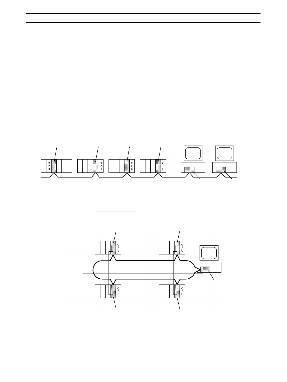
The network is connected using either shielded twisted-pair cable or optical
fiber cable, and high-volume data transmissions at high speed enable construction of a wide range of networks, from low-level systems to high.
Wired System
(Twisted-pair Cable)
Optical Bus or Optical
Ring System
(H-PCF Cable)
Wired Systems are supported by CS-series, CJ-series, C200HX/HG/HE,
CQM1H-series CVM1, and CV-series PCs.
Optical Systems are supported by CS-series, CVM1, and CV-series PCs.
Token Ring Mode
2
Overview Section 1-1
CS1W-CLK12
Controller Link Unit
(Token-bus mode)
CS1W-CLK11
Controller Link Unit
CVM1-CLK12
Controller Link Unit
(Token-bus mode)
3G8F5-CLK11
Controller Link
ISA Support Board
CS-series PC
CS-series PC
CVM1 or
CV-series
PC
Backup power
supply (24 VDC)
H-PCF Optical Fiber Cable
(daisy-chain connection)
IBM PC/AT or
compatible
3G8F7-CLK12-EV1
Controller Link
PCI Support Board
(Token bus mode)
IBM PC/AT or
compatible
CS1W-CLK52
Controller Link Unit
(Token Ring Mode)
CVM1-CLK52
Controller Link Unit
(Token Ring Mode)
CS1W-CLK52
Controller Link Unit
(Token Ring Mode)
CVM1-CLK52
Controller Link Unit
(Token Ring Mode)
Backup power
supply (24 VDC)
CS-series PC
CVM1 or
CV-series
PC
CVM1 or
CV-series
PC
CS-series PC
GI Optical Fiber Cable
(ring connection)
3G8F7-CLK52-EV1
Controller Link
PCI Support Board
(Token Ring Mode)
IBM PC/AT or
compatible
CS1W-CLK52
Controller Link Unit
(Token-bus mode)
CS-series PC
CS-series PC
CVM1 or
CV-series PC
Backup power
supply (24 VDC)
GI Optical Fiber Cable
(daisy-chain connection)
CS1W-CLK52
Controller Link Unit
(Token-bus mode)
CVM1-CLK52
Controller Link Unit
(Token-bus mode)
3G8F7-CLK52-EV1
Controller Link
PCI Support Board
(Token bus mode)
IBM PC/AT or
compatible
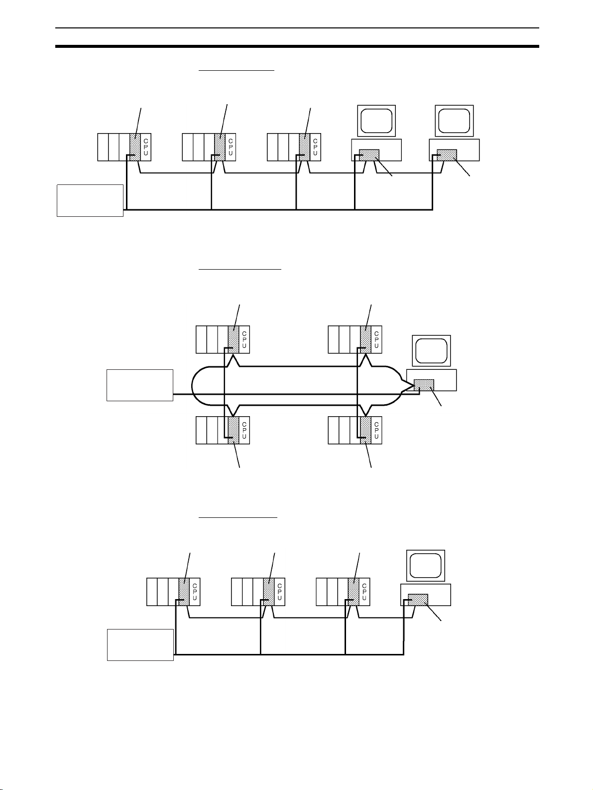
Tokenbus Mode
Optical Bus or Optical
Ring System (GI Cable)
Optical Systems are supported by CS-series, CJ-series, CVM1, and CVseries PCs.
Token Ring Mode
Token-bus Mode
3

Overview Section 1-1
Data link
Manual settings
Automatic settings
Message service
RAS functions Error log function
Data link status display
Polling node backup
function
Controller Link
Node bypass function
Transmission path
duplication
Disconnect detection and
notification
Node connection
configuration data reading
Note 1. Optical Systems and Optical Ring Sys-
tems only.
2. Only for Optical Ring Systems in Token
Ring Mode.
(See note 1.)
(See note 2.)
(See note 2.)
(See note 2.)
The functions of a Controller Link Network are outlined below.
1-1-2 Features
The Controller Link FA Network has the following features to meet the various
requirements of FA sites.
Data Links Flexible and efficient data links can be created for large capacities of data as
Number of
data link
words
Item Specifications
listed below.
Send areas
per node
Data link
areas (send
and receive)
that can be
created per
node
CS or CJ Series CS1W-CLK23 or CJ1W-CLK23:
C200HX/HG/HE,
CVM1/CV, CQM1H
Computers 3G8F7-CLK23-E: 4,000 words max.
CS or CJ Series CS1W-CLK23 or CJ1W-CLK23:
C200HX/HG/HE,
CVM1/CV, or CQM1H
Computers 32,000 or 62,000 words max. (See note 2.)
CS1W-CLK21-EV1 or CJ1W-CLK21-EV1:
1,000 words max.
3G8F7-CLK21-EV1, 3G8F5-CLK21-E1:
CS1W-CLK21-EV1 or CJ1W-CLK21-EV1:
8,000 words max.
4,000 words max.
1,000 words max.
1,000 words max.
20,000 words max.
20,000 words max. (unit version 1.2 or later)
12,000 words max. (Pre-Ver. 1.2)
4

Overview Section 1-1
Note The following models must be used to create a wired network that contains
more than 32 nodes: 3G8F7-CLK23-E, 3G8F7-CLK21-EV1, CS1W-CLK23,
CS1W-CLK21-V1, CJ1W-CLK23, and CJ1W-CLK21-V1.
Data links can be automatic set, or they can be set by the user to freely
change the sizes of the data areas used. A data link can also receive only part
of the data sent from another node. This function enables users to receive
only the required data, thereby increasing data link efficiency.
Message Service The message service can send and receive up to 2,012 bytes of data (includ-
ing the FINS header), allowing high volumes of data to be sent and received
without having to split it up.
Twisted-pair Cable or Optical Fiber Cable Connection
The Controller Link Units can be connected to the network using either
shielded twisted-pair cables, optical fiber cables, or optical ring optical fiber
cables. The optical ring optical fiber cables can be either H-PCF cables or GI
cables. Select the system that suits the application.
Features of Twisted-pair Cable
Twisted-pair cable is easy to connect and maintain. The cable can be processed much more easily than coaxial or optical cable, thereby reducing the
cost of tools and assembly time.
Connections are made to a terminal block on the Controller Link Unit and to a
special connector on the computer board for easy system assembly and modification.
The network is equipped with the required terminating resistance built into the
Units allowing the terminating resistance to be easily set at both ends of the
network using a simple switch.
Features of Optical and Optical Ring Systems
Optical fiber cable (H-PCF cable or GI cable) has superior noise resistance,
so the system can provide highly reliable communications even in very noisy
conditions.
With H-PCF cable, the total communications distance can be up to 20 km
(1 km max. between nodes using adhesive polishing). With GI cable, the communications distance can be up to 30 km (2 km max. between nodes using
62.5/125 μm cable), which allows long-distance and large-scale networks.
Once the optical fiber cable has been fitted with special connectors, the
cables can be easily connected or disconnected.
Communications between Different PCs
The following Controller Link Units are available for communications between
different PCs. Wired Units and Optical Units, however, cannot be used
together in the same Controller Link Network. (Optical and Optical Ring Units
can exist in one Controller Link Network using H-PCF cables, but with GI
cables, on an Optical Ring Unit is available.)
Wired System
• Controller Link Unit for CS-series Programmable Controllers
• Controller Link Unit for CJ-series Programmable Controllers
• Controller Link Units for C200HX/HG/HE Programmable Controllers
• Controller Link Units for CV-series Programmable Controllers
• ISA Bus Controller Link Support Board for IBM PC/AT or compatibles
5
Overview Section 1-1
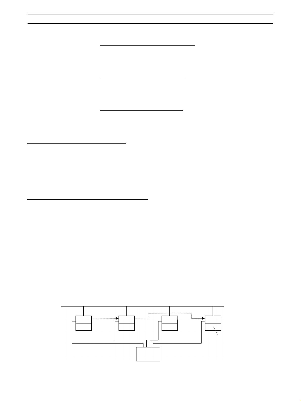
Optical transmission path
Bypass
IBM PC/AT or
compatible
Power interruption
24-VDC
Backup Power Supply
CLK
PC
CLK
PC
CLK
PC
CLK
• PCI Bus Controller Link Support Board
Optical Ring System with H-PCF Cables
• Controller Link Unit for CS-series Programmable Controllers
• Controller Link Unit for CVM1/CV-series Programmable Controllers
• PCI Bus Controller Link Support Board
Optical Ring System with GI Cables
• CS-series and CJ-series Programmable Controllers
• CVM1/CV-series Programmable Controllers
• PCI Bus Boards
Optical System with H-PCF Cables
• Controller Link Unit for CS-series and CJ-series Programmable Controllers
• ISA Bus Controller Link Support Board for IBM PC/AT or compatibles
Flexible Internetwork Connections
The Controller Link Network can be connected to another network (Ethernet,
SYSMAC NET Link, SYSMAC LINK, or another Controller Link network)
through a CS-series or CV-series PC. By installing Ethernet, SYSMAC NET
Link, or SYSMAC LINK, or Controller Link Communications Units on the same
CS1-series PC or CV-series PC, a message service can be created with
nodes in the interconnected networks through that PC. Up to three network
levels are possible.
Improved Error Handling (RAS Functions)
Error Log and Data Link
Status Display
Polling Node Backup
Function
Node Bypass Function In an Optical or Optical Ring Controller Link Network, data communications
An error log enables quick handling of errors by recording the time the error
occurred and error details. The current Controller Link Unit and Support Board
status are also available, as are the data link and network status.
When an error occurs in the polling node that controls the Controller Link Network, another node automatically becomes the polling node with the help of
the Polling node backup function. This prevents an error at a single node from
influencing other nodes on the network, achieving a highly reliable system.
can be continued by bypassing the node, even when a node in the communications line malfunctions or the PC or computer power supply is turned OFF.
This prevents the whole network system from being affected by a node malfunction or power interruption.
To use the bypass node function, backup power must be supplied to the Controller Link Unit/Support Board.
6

Overview Section 1-1
Transmission Path
Duplication
Disconnect Detection and
Notification
Node Connection
Configuration Data
Reading
In Token Ring Mode in an Optical Ring System (H-PCF cable or GI cable),
data transmission will be unaffected even by a cable or connector break at
one location in the ring connection. With the optical cable wired in a ring
shape, a break at one point will simply cause the transmission to be routed on
the other path.
Even with transmission path duplication, the network will be broken if disconnections occur in two or more places. In Token Ring Mode in an Optical Ring
System (H-PCF cable or GI cable), the location of a disconnection can be
detected and identified by means of the node status information given for all
nodes. This function can be used to prevent system crashes in advance, e.g.,
by performing maintenance when a disconnection occurs at one location.
In Token Ring Mode in an Optical Ring System (H-PCF cable or GI cable),
connection data can be read for all of the nodes in the network. The information that can be read includes the order in which the nodes are connected and
which of two optical connectors is connected to which node. Special support
software (Controller Link Support Software, Ver. 2.00 or later) is required to
read the node connection configuration data.
Using Repeater Units for T-Branches, Network Extensions, Network Expansions,
Converting Network Sections to Optical Fiber, and Device Modularization
T-Branches enable greater wiring freedom during layout, restructuring, and expansion of
networks.
Wire-to-Wire Repeater Units enable Controller Link T-Branches. T-Branches
provide the following advantages:
• Cabling can conform to the layout of equipment.
• It is possible to add nodes by adding or inserting Repeater Units at
branch points of an existing wired Controller Link system.
• If Repeater Units are installed at likely future branch points in the network
in advance, new nodes can be added by simply connecting them to these
Repeater Units.
The total length of wired networks can be extended.
At a baud rate of 2 Mbps, conventional wired networks can be up to 500 m
long. By using two Repeater Units, this can be extended to a maximum of
1.5 km.
The maximum number of nodes can be extended to 62 for wired networks.
By combining version-1 Controller Link Units/Support Boards and a Repeater
Unit, it is possible to construct networks containing up to 62 nodes.
Improved noise resistance through the use of optical cabling.
By installing two Wire-to-Optical Repeater Units, optical cabling can be used
for sections of the network that are the source of noise.
Devices can be modularized.
• Devices can be modularized according to Repeater Units, making wiring
easier when adding, removing, or modifying devices.
• When starting up devices, components can be added to the network and
debugged as they are completed.
Refer to the Controller Link Unit Operation Manual (W309) for information on
using Repeater Units.
7

Overview Section 1-1
Features and Functions of Version-1 and CLK23 Models
The following features and functions apply to the CS1W-CLK23, CS1WCLK21-V1, CJ1W-CLK23, and CJ1W-CLK21-V1 Controller Link Units and the
3G8F7-CLK23-E and 3G8F7-CLK21-EV1 Controller Link Support Board only.
Up to 62 nodes can be connected.
Overview
When a CS1W-RPT01 Repeater Unit is used, the maximum number of nodes
that can be used in the network increases to 62. (The previous limit was 32.)
Method
Use Repeater Units and select Max Node Number set 62 in the FinsGateway
drive settings to enable a maximum of 62 nodes.
Restrictions
• The maximum of 62 nodes cannot be achieved if pre-version-1 models
are used together in the same network with version-1 models or with
CLK23 models (i.e., the CS1W-CLK23, CJ1W-CLK23, or 3G8F7-CLK23E).
• Using the maximum 62 nodes can be enabled using FinsGateway 2003.
This setting is not possible with FinsGateway version 3.@@.
Automatic data link creation is possible with 1:N allocations.
Overview
It is possible to perform unequal 1:N allocations of data between nodes with
automatic data link creation. This makes it easy to perform data links that formerly required the user to manually edit data link parameters.
The following four automatic data link creation patterns can be used:
• Equality layout (the previous pattern)
• 1:N allocation, common type
• 1:N allocation, 1 to 1 type
• 1:N allocation, chain type
This setting can be made in CS-series or CJ-series Controller Link Units.
Method
Allocation addresses and sizes are all specified using the Automatic Data Link
Creation Parameters (D30000 × Unit No. + 12 to 20) in the DM Parameter
Area. These values can be set using the CX-Net in the CX-Programmer version 3.2 or later.
Objective
This function is effective in applications that collect data from slave PCs into a
master PC.
Restrictions
• A Controller Link Support Board cannot be set as the startup node.
• These settings can be made using FinsGateway 2003. They are not possible with FinsGateway version 3.@@.
Automatic data link creation with 1:N allocations cannot be performed if preversion-1 models are used together in the same network with version-1 models or with CLK23 models (i.e., the CS1W-CLK23, CJ1W-CLK23, or 3G8F7CLK23-E).
8

Overview Section 1-1
Change manually created data link tables during data link operation.
Overview
It is possible to modify a manually created data link table while data links are
running.
Note This is possible only with manually created data link tables. Any attempt to
change automatically created data link tables when data links are running will
fail and an error message saying that the tables cannot be edited during data
link operation will be displayed.
Method
This function can be set using the CX-Net in CX-Programmer version 3.2 or
later.
Objectives
• In systems that operate non-stop and cannot be turned OFF, this function
makes it possible to change the data link table to accommodate the addition of new nodes and to transfer data link tables without having to stop
manually set data link communications.
• If this function is combined with the use of Repeater Units to add network
nodes, it becomes possible to construct systems of greater flexibility.
Operation
When a node is being modified online, this function temporarily stops refreshing of data link data until modifications have been completed.
Nodes will participate in data links after changes to the data link table have
been completed.
Note Refer to the Controller Link Unit Operation Manual (W309) for information on
changing user-set data link tables while the data links are active.
Overview of 3G8F7-CLK23-E, 3G8F7-CLK13-E, and 3G8F7-CLK53-E Features and Functions
The 3G8F7-CLK23-E, 3G8F7-CLK13-E, and 3G8F7-CLK53-E are upwardly
compatible from the 3G8F7-CLK21-EV1, 3G8F7-CLK12-EV1, and 3G8F7CLK52-EV1, respectively.
The following data link functions have been added to the features and functions of the 3G8F7-CLK21-EV1, 3G8F7-CLK12-EV1, and 3G8F7-CLK52EV1.
All other functions and performance are the same as for the 3G8F7-CLK21EV1, 3G8F7-CLK12-EV1, and 3G8F7-CLK52-EV1.
Model number 3G8F7-CLK21-EV1,
3G8F7-CLK12-EV1, or
3G8F7-CLK52-EV1
Number of send
words per node (total
of area 1 and area 2)
Number of error log
records
1,000 words max. 4,000 words max.
39 max. 64 max.
3G8F7-CLK23-E,
3G8F7-CLK13-E, or
3G8F7-CLK53-E
When configuring a system using data links in which the number of send
words per node exceeds 1,000 words, all Controller Link Units and Support
Boards must be the CS1W-CLK@3, CJ1W-CLK@3, or 3G8F7-CLK@3-E.
When using other Controller Link Units or Support Boards together in the
same network, use a maximum of 1,000 send words per node.
9
Overview Section 1-1
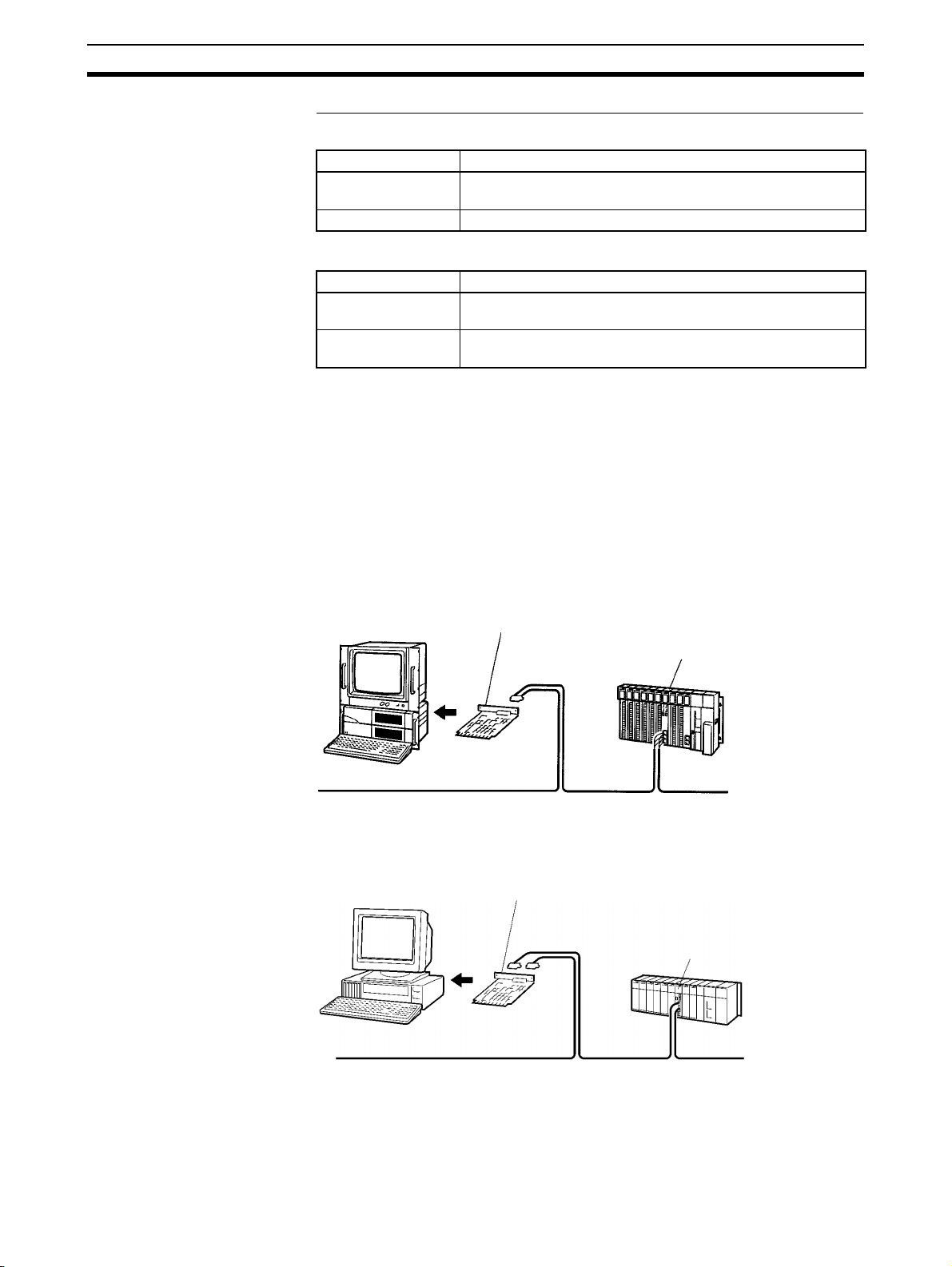
Controller Link Network
3G8F7-CLK21-EV1 (for PCI Bus) or
3G8F5-CLK21-E (for ISA Bus)
Controller Link Support Board
Controller Link Unit
PC
IBM PC/AT or
compatible
Optical System/Optical Ring System (H-PCF Cable) Controller Link Network
3G8F7-CLK12-EV1 (for PCI Bus) or
3G8F5-CLK11-E (for ISA Bus)
Controller Link Support Board
Controller Link Unit
PC
IBM PC/AT or
compatible
Units and Support Boards Supporting Up to 4,000 Send Words Per Node
Wired Networks
Model
Units CS1W-CLK23 (CS-series Unit)
CJ1W-CLK23 (CJ-series Unit)
Support Board 3G8F7-CLK23-E (Support Board for PCI Bus)
Optical Networks
Model
Units CS1W-CLK13 (CS-series Unit, H-PCF Cable)
Support Board 3G8F7-CLK13-E (Support Board for PCI Bus, H-PCF Cable)
CS1W-CLK53 (CJ-series Unit, GI Cable)
3G8F7-CLK53-E (Support Board for PCI Bus, GI Cable)
1-1-3 What Is a Controller Link Support Board?
A Controller Link Support Board is used to directly connect an IBM PC/AT or
compatible with an ICA or PCI bus to a Controller Link Network. A Controller
Link Support Board supports data links, a message service, and RAS functions in the same way as a Controller Link Unit.
The Support Board is mounted in an expansion slot in the computer. The following Support Boards are available depending on the type of connection
cable.
Wired System
Optical System/Optical Ring System (H-PCF Cable)
10
 Loading...