

Page 1

Cat. No. W382-E1-04
WS02-CFDC1-E DeviceNet Configurator
3G8F5-DRM21-E ISA Board
3G8E2-DRM21-EV1 PCMCIA Card
DeviceNet Configurator
Ver. 2.@
OPERATION MANUAL
Page 2

WS02-CFDC1-E DeviceNet Configurator
3G8F5-DRM21-E ISA Board
3G8E2-DRM21-EV1 PCMCIA Card
DeviceNet Configurator Ver. 2.@
Operation Manual
Revised September 2005
Page 3

iv
Page 4

Notice:
OMRON products are manufactured for use according to proper procedures by a qualified operator
and only for the purposes described in this manual.
The following conventions are used to indicate and classify precautions in this manual. Always heed
the information provided with them. Failure to heed precautions can result in injury to people or damage to property.
!DANGER Indicates an imminently hazardous situation which, if not avoided, will result in death or
serious injury. Additionally, there may be severe property damage.
!WARNING Indicates a potentially hazardous situation which, if not avoided, could result in death or
serious injury. Additionally, there may be severe property damage.
!Caution Indicates a potentially hazardous situation which, if not avoided, may result in minor or
moderate injury, or property damage.
OMRON Product References
All OMRON products are capitalized in this manual. The word “Unit” is also capitalized when it refers to
an OMRON product, regardless of whether or not it appears in the proper name of the product.
The abbreviation “Ch,” which appears in some displays and on some OMRON products, often means
“word” and is abbreviated “Wd” in documentation in this sense.
The abbreviation “PLC” means Programmable Controller. “PC” is used, however, in some Programming Device displays to mean Programmable Controller.
Visual Aids
The following headings appear in the left column of the manual to help you locate different types of
information.
Note Indicates information of particular interest for efficient and convenient opera-
tion of the product.
Reference Indicates supplementary information on related topics that may be of interest
to the user.
1,2,3... 1. Indicates lists of one sort or another, such as procedures, checklists, etc.
Trademarks and Copyrights
DeviceNet is a registered trademark of the Open DeviceNet Vendor Association, Inc.
Windows, Windows 95, Windows 98, Windows Me, Windows NT, Windows 2000 and Windows XP are
registered trademarks of the Microsoft Corporation.
Other product names and company names in this manual are trademarks or registered trademarks of
their respective companies.
The copyright of the DeviceNet Configurator software belongs to OMRON Corporation.
OMRON, 2000
All rights reserved. No part of this publication may be reproduced, stored in a retrieval system, or transmitted, in any form, or
by any means, mechanical, electronic, photocopying, recording, or otherwise, without the prior written permission of
OMRON.
No patent liability is assumed with respect to the use of the information contained herein. Moreover, because OMRON is constantly striving to improve its high-quality products, the information contained in this manual is subject to change without
notice. Every precaution has been taken in the preparation of this manual. Nevertheless, OMRON assumes no responsibility
for errors or omissions. Neither is any liability assumed for damages resulting from the use of the information contained in
this publication.
v
Page 5

vi
Page 6

TABLE OF CONTENTS
PRECAUTIONS . . . . . . . . . . . . . . . . . . . . . . . . . . . . . . . . xv
1 Intended Audience . . . . . . . . . . . . . . . . . . . . . . . . . . . . . . . . . . . . . . . . . . . . . . . . . xvi
2 General Precautions . . . . . . . . . . . . . . . . . . . . . . . . . . . . . . . . . . . . . . . . . . . . . . . . xvi
3 Safety Precautions. . . . . . . . . . . . . . . . . . . . . . . . . . . . . . . . . . . . . . . . . . . . . . . . . . xvi
4 Operating Environment Precautions . . . . . . . . . . . . . . . . . . . . . . . . . . . . . . . . . . . . xvii
5 Application Precautions . . . . . . . . . . . . . . . . . . . . . . . . . . . . . . . . . . . . . . . . . . . . . xviii
SECTION 1
Overview . . . . . . . . . . . . . . . . . . . . . . . . . . . . . . . . . . . . . . 1
1-1 Introduction. . . . . . . . . . . . . . . . . . . . . . . . . . . . . . . . . . . . . . . . . . . . . . . . . . . . . . . 2
1-2 Confirming Product Contents . . . . . . . . . . . . . . . . . . . . . . . . . . . . . . . . . . . . . . . . . 11
1-3 Operating Environment . . . . . . . . . . . . . . . . . . . . . . . . . . . . . . . . . . . . . . . . . . . . . . 12
SECTION 2
Installation . . . . . . . . . . . . . . . . . . . . . . . . . . . . . . . . . . . . . 15
2-1 Installation Procedure . . . . . . . . . . . . . . . . . . . . . . . . . . . . . . . . . . . . . . . . . . . . . . . 16
2-2 ISA Board Installation . . . . . . . . . . . . . . . . . . . . . . . . . . . . . . . . . . . . . . . . . . . . . . 16
2-3 PCMCIA Card Installation . . . . . . . . . . . . . . . . . . . . . . . . . . . . . . . . . . . . . . . . . . . 24
2-4 Configurator Installation. . . . . . . . . . . . . . . . . . . . . . . . . . . . . . . . . . . . . . . . . . . . . 32
SECTION 3
Basic Operation . . . . . . . . . . . . . . . . . . . . . . . . . . . . . . . . . 37
3-1 Starting the Configurator and the Main Window . . . . . . . . . . . . . . . . . . . . . . . . . . 38
3-2 Menu Commands . . . . . . . . . . . . . . . . . . . . . . . . . . . . . . . . . . . . . . . . . . . . . . . . . . 41
3-3 Connecting to the Network . . . . . . . . . . . . . . . . . . . . . . . . . . . . . . . . . . . . . . . . . . . 46
3-4 Operation Flowcharts . . . . . . . . . . . . . . . . . . . . . . . . . . . . . . . . . . . . . . . . . . . . . . . 58
SECTION 4
Editing Device Parameters. . . . . . . . . . . . . . . . . . . . . . . . 59
4-1 Adding Devices to the Virtual Network . . . . . . . . . . . . . . . . . . . . . . . . . . . . . . . . . 60
4-2 Setting Slave Parameters. . . . . . . . . . . . . . . . . . . . . . . . . . . . . . . . . . . . . . . . . . . . . 64
4-3 Adding Slaves to the Master . . . . . . . . . . . . . . . . . . . . . . . . . . . . . . . . . . . . . . . . . . 68
4-4 Setting Master Properties . . . . . . . . . . . . . . . . . . . . . . . . . . . . . . . . . . . . . . . . . . . . 71
4-5 Editing Master Parameters . . . . . . . . . . . . . . . . . . . . . . . . . . . . . . . . . . . . . . . . . . . 73
4-6 Parameter Wizard . . . . . . . . . . . . . . . . . . . . . . . . . . . . . . . . . . . . . . . . . . . . . . . . . . 74
4-7 Master Parameter Editing Details (Tab Descriptions) . . . . . . . . . . . . . . . . . . . . . . 78
4-8 Manual I/O Allocations. . . . . . . . . . . . . . . . . . . . . . . . . . . . . . . . . . . . . . . . . . . . . . 84
4-9 Advanced Settings
(Connection, Communication Cycle Time, Slave Function Settings, Etc.) . . . . . . 91
4-10 Creating and Editing I/O Comments. . . . . . . . . . . . . . . . . . . . . . . . . . . . . . . . . . . . 96
4-11 Displaying Device Properties . . . . . . . . . . . . . . . . . . . . . . . . . . . . . . . . . . . . . . . . . 98
vii
Page 7

TABLE OF CONTENTS
SECTION 5
Online Operation . . . . . . . . . . . . . . . . . . . . . . . . . . . . . . . . 105
5-1 Switching between Online and Offline . . . . . . . . . . . . . . . . . . . . . . . . . . . . . . . . . 106
5-2 Downloading the Network Configuration/Device Parameters to Devices . . . . . . 108
5-3 Uploading and Verifying Device Parameters. . . . . . . . . . . . . . . . . . . . . . . . . . . . . 113
5-4 Monitoring Devices . . . . . . . . . . . . . . . . . . . . . . . . . . . . . . . . . . . . . . . . . . . . . . . . 117
SECTION 6
Manipulating Files. . . . . . . . . . . . . . . . . . . . . . . . . . . . . . . 127
6-1 Saving and Reading Files . . . . . . . . . . . . . . . . . . . . . . . . . . . . . . . . . . . . . . . . . . . 128
6-2 EDS File Management. . . . . . . . . . . . . . . . . . . . . . . . . . . . . . . . . . . . . . . . . . . . . . 129
6-3 Printing . . . . . . . . . . . . . . . . . . . . . . . . . . . . . . . . . . . . . . . . . . . . . . . . . . . . . . . . . 133
6-4 Using General-purpose Tools to Set Devices . . . . . . . . . . . . . . . . . . . . . . . . . . . . 133
6-5 Exporting Data Created in Configurator . . . . . . . . . . . . . . . . . . . . . . . . . . . . . . . . 137
6-6 Importing Files Created in Version 1 of the Configurator. . . . . . . . . . . . . . . . . . . 138
6-7 Optional Functions . . . . . . . . . . . . . . . . . . . . . . . . . . . . . . . . . . . . . . . . . . . . . . . . 139
Appendices
A Error Messages . . . . . . . . . . . . . . . . . . . . . . . . . . . . . . . . . . . . . . . . . . . . . . . . . . . 143
B Troubleshooting . . . . . . . . . . . . . . . . . . . . . . . . . . . . . . . . . . . . . . . . . . . . . . . . . . 147
C Error History Information . . . . . . . . . . . . . . . . . . . . . . . . . . . . . . . . . . . . . . . . . . . 149
D Unit Replacement . . . . . . . . . . . . . . . . . . . . . . . . . . . . . . . . . . . . . . . . . . . . . . . . . 155
E Replacing the C200HW-DRM21-V1 on a CS-series CPU Rack
with the CS1W-DRM21 . . . . . . . . . . . . . . . . . . . . . . . . . . . . . . . . . . . . . . . . . . . . 157
F Replacing the C200HW-DRT21 with the CS1W-DRM21’s Slave Functions . . . 159
G Dimensions of PCMCIA Card and Unit . . . . . . . . . . . . . . . . . . . . . . . . . . . . . . . . 161
Index. . . . . . . . . . . . . . . . . . . . . . . . . . . . . . . . . . . . . 163
Revision History . . . . . . . . . . . . . . . . . . . . . . . . . . . . . . . . 167
viii
Page 8

About this Manual:
This manual describes the installation and operation of version 2 of the DeviceNet Configurator and
includes the sections described below.
Please read this manual and all manuals for related products carefully and be sure you understand the
information provided before attempting to install and operate the DeviceNet Configurator. Be sure to
read the precautions provided in the following section.
Section 1 Section 1 describes the features, specifications, operating conditions, and interfaces of the
DeviceNet Configurator.
Section 2 Section 2 explains how to install the ISA Board or PCMCIA Card hardware in the computer,
make the necessary hardware settings and computer settings, and install the DeviceNet Configurator
software in the computer.
Section 3 Section 3 explains the basic operation of the DeviceNet Configurator.
Section 4 Section 4 explains how to enable remote I/O communications by creating device parameters
for a virtual network constructed with the DeviceNet Configurator.
Section 5 Section 5 explains the online operation of the DeviceNet Configurator, such as data downloading to or uploading from devices and device monitoring.
Section 6 Section 6 provides information on manipulating files, including saving and reading procedures.
The Appendices provide information on error messages, troubleshooting, the error history, Unit
replacement, replacing the C200HW-DRM21-V1 on a CS1-series PLC with the CS1W-DRM21, replacing the C200HW-DRT21 with the CS1W-DRM21’s slave functions, and the dimensions of PCMCIA
Card and Unit.
The following manuals provide information on the DeviceNet and OMRON DeviceNet products.
Manual Products Contents Cat. No.
DeviceNet Configurator
Ver. 2.@
Operation Manual
(This manual)
CS/CJ-series DeviceNet
Unit Operation Manual
DeviceNet
(CompoBus/D)
Operation Manual
WS02-CFDC1-E
DeviceNet Configurator
3G8F5-DRM21-E ISA Board
3G8E2-DRM21-EV1 PCMCIA
Card
CS1W-DRM21
CJ1W-DRM21
DeviceNet Unit
CVM1-DRM21-V1
DeviceNet Master Unit
C200HW-DRM21-V1
DeviceNet Master Unit
Information on using the
Configurator.
Information on CS/CJ-series
DeviceNet Units.
Information on C200H-series,
CVM1, and CV-series DeviceNet
Units, as well as general DeviceNet
communications specifications and
wiring methods.
W382
W380
W267
!WARNING Failure to read and understand the information provided in this manual may result in per-
sonal injury or death, damage to the product, or product failure. Please read each section
in its entirety and be sure you understand the information provided in the section and
related sections before attempting any of the procedures or operations given.
ix
Page 9

x
Page 10

Read and Understand this Manual
Please read and understand this manual before using the product. Please consult your OMRON
representative if you have any questions or comments.
Warranty and Limitations of Liability
WARRANTY
OMRON's exclusive warranty is that the products are free from defects in materials and workmanship for a
period of one year (or other period if specified) from date of sale by OMRON.
OMRON MAKES NO WARRANTY OR REPRESENTATION, EXPRESS OR IMPLIED, REGARDING NONINFRINGEMENT, MERCHANTABILITY, OR FITNESS FOR PARTICULAR PURPOSE OF THE
PRODUCTS. ANY BUYER OR USER ACKNOWLEDGES THAT THE BUYER OR USER ALONE HAS
DETERMINED THAT THE PRODUCTS WILL SUITABLY MEET THE REQUIREMENTS OF THEIR
INTENDED USE. OMRON DISCLAIMS ALL OTHER WARRANTIES, EXPRESS OR IMPLIED.
LIMITATIONS OF LIABILITY
OMRON SHALL NOT BE RESPONSIBLE FOR SPECIAL, INDIRECT, OR CONSEQUENTIAL DAMAGES,
LOSS OF PROFITS OR COMMERCIAL LOSS IN ANY WAY CONNECTED WITH THE PRODUCTS,
WHETHER SUCH CLAIM IS BASED ON CONTRACT, WARRANTY, NEGLIGENCE, OR STRICT
LIABILITY.
In no event shall the responsibility of OMRON for any act exceed the individual price of the product on which
liability is asserted.
IN NO EVENT SHALL OMRON BE RESPONSIBLE FOR WARRANTY, REPAIR, OR OTHER CLAIMS
REGARDING THE PRODUCTS UNLESS OMRON'S ANALYSIS CONFIRMS THAT THE PRODUCTS
WERE PROPERLY HANDLED, STORED, INSTALLED, AND MAINTAINED AND NOT SUBJECT TO
CONTAMINATION, ABUSE, MISUSE, OR INAPPROPRIATE MODIFICATION OR REPAIR.
xi
Page 11

Application Considerations
SUITABILITY FOR USE
OMRON shall not be responsible for conformity with any standards, codes, or regulations that apply to the
combination of products in the customer's application or use of the products.
At the customer's request, OMRON will provide applicable third party certification documents identifying
ratings and limitations of use that apply to the products. This information by itself is not sufficient for a
complete determination of the suitability of the products in combination with the end product, machine,
system, or other application or use.
The following are some examples of applications for which particular attention must be given. This is not
intended to be an exhaustive list of all possible uses of the products, nor is it intended to imply that the uses
listed may be suitable for the products:
• Outdoor use, uses involving potential chemical contamination or electrical interference, or conditions or
uses not described in this manual.
• Nuclear energy control systems, combustion systems, railroad systems, aviation systems, medical
equipment, amusement machines, vehicles, safety equipment, and installations subject to separate
industry or government regulations.
• Systems, machines, and equipment that could present a risk to life or property.
Please know and observe all prohibitions of use applicable to the products.
NEVER USE THE PRODUCTS FOR AN APPLICATION INVOLVING SERIOUS RISK TO LIFE OR
PROPERTY WITHOUT ENSURING THAT THE SYSTEM AS A WHOLE HAS BEEN DESIGNED TO
ADDRESS THE RISKS, AND THAT THE OMRON PRODUCTS ARE PROPERLY RATED AND
INSTALLED FOR THE INTENDED USE WITHIN THE OVERALL EQUIPMENT OR SYSTEM.
PROGRAMMABLE PRODUCTS
OMRON shall not be responsible for the user's programming of a programmable product, or any
consequence thereof.
xii
Page 12

Disclaimers
CHANGE IN SPECIFICATIONS
Product specifications and accessories may be changed at any time based on improvements and other
reasons.
It is our practice to change model numbers when published ratings or features are changed, or when
significant construction changes are made. However, some specifications of the products may be changed
without any notice. When in doubt, special model numbers may be assigned to fix or establish key
specifications for your application on your request. Please consult with your OMRON representative at any
time to confirm actual specifications of purchased products.
DIMENSIONS AND WEIGHTS
Dimensions and weights are nominal and are not to be used for manufacturing purposes, even when
tolerances are shown.
PERFORMANCE DATA
Performance data given in this manual is provided as a guide for the user in determining suitability and does
not constitute a warranty. It may represent the result of OMRON's test conditions, and the users must
correlate it to actual application requirements. Actual performance is subject to the OMRON Warranty and
Limitations of Liability.
ERRORS AND OMISSIONS
The information in this manual has been carefully checked and is believed to be accurate; however, no
responsibility is assumed for clerical, typographical, or proofreading errors, or omissions.
xiii
Page 13

xiv
Page 14

PRECAUTIONS
This section provides general precautions for using the DeviceNet Configurator and related devices.
The information contained in this section is important for the safe and reliable application of the DeviceNet
Configurator and personal computer. You must read this section and understand the information contained before
attempting to set up or operate a DeviceNet Configurator and personal computer.
1 Intended Audience . . . . . . . . . . . . . . . . . . . . . . . . . . . . . . . . . . . . . . . . . . . . . xvi
2 General Precautions . . . . . . . . . . . . . . . . . . . . . . . . . . . . . . . . . . . . . . . . . . . . xvi
3 Safety Precautions. . . . . . . . . . . . . . . . . . . . . . . . . . . . . . . . . . . . . . . . . . . . . . xvi
4 Operating Environment Precautions . . . . . . . . . . . . . . . . . . . . . . . . . . . . . . . . xvii
5 Application Precautions . . . . . . . . . . . . . . . . . . . . . . . . . . . . . . . . . . . . . . . . . xviii
xv
Page 15

Intended Audience 1
1 Intended Audience
This manual is intended for the following personnel, who must also have
knowledge of electrical systems (an electrical engineer or the equivalent).
• Personnel in charge of installing FA systems.
• Personnel in charge of designing FA systems.
• Personnel in charge of managing FA systems and facilities.
2 General Precautions
The user must operate the product according to the performance specifications described in the operation manuals.
Before using the product under conditions which are not described in the
manual or applying the product to nuclear control systems, railroad systems,
aviation systems, vehicles, combustion systems, medical equipment, amusement machines, safety equipment, and other systems, machines, and equipment that may have a serious influence on lives and property if used
improperly, consult your OMRON representative.
Make sure that the ratings and performance characteristics of the product are
sufficient for the systems, machines, and equipment, and be sure to provide
the systems, machines, and equipment with double safety mechanisms.
This manual provides information for installing and operating the DeviceNet
Configurator. Be sure to read this manual before operation and keep this manual close at hand for reference during operation.
!WARNING It is extremely important that a PLC and all PLC Units be used for the speci-
fied purpose and under the specified conditions, especially in applications that
can directly or indirectly affect human life. You must consult with your OMRON
representative before applying a PLC System to the above-mentioned applications.
3 Safety Precautions
!WARNING Never attempt to disassemble a Board or Card or touch the inside of a Board
or Card while power is being supplied. Doing so may result in serious electrical shock or electrocution.
!WARNING Provide safety measures in external circuits, i.e., not in the Programmable
Controller (CPU Unit including associated Units; referred to as “PLC”), in
order to ensure safety in the system if an abnormality occurs due to malfunction of the PLC or another external factor affecting the PLC operation. Not
doing so may result in serious accidents.
• Emergency stop circuits, interlock circuits, limit circuits, and similar safety
measures must be provided in external control circuits.
• The PLC will turn OFF all outputs when its self-diagnosis function detects
any error or when a severe failure alarm (FALS) instruction is executed.
As a countermeasure for such errors, external safety measures must be
provided to ensure safety in the system.
• The PLC outputs may remain ON or OFF due to deposition or burning of
the output relays or destruction of the output transistors. As a counter-
xvi
Page 16

Operating Environment Precautions 4
measure for such problems, external safety measures must be provided
to ensure safety in the system.
• When the 24-VDC output (service power supply to the PLC) is overloaded
or short-circuited, the voltage may drop and result in the outputs being
turned OFF. As a countermeasure for such problems, external safety
measures must be provided to ensure safety in the system.
!WARNING The CPU Unit refreshes I/O even when the program is stopped (i.e., even in
PROGRAM mode). Confirm safety thoroughly in advance before changing the
status of any part of memory allocated to I/O Units, Special I/O Units, or CPU
Bus Units. Any changes to the data allocated to any Unit may result in unexpected operation of the loads connected to the Unit. Any of the following operation may result in changes to memory status.
• Transferring I/O memory data to the CPU Unit from a Programming
Device.
• Changing present values in memory from a Programming Device.
• Force-setting/-resetting bits from a Programming Device.
• Transferring I/O memory files from a Memory Card or EM file memory to
the CPU Unit.
• Transferring I/O memory from a host computer or from another PLC on a
network.
!Caution Confirm safety at the destination node before transferring a program to
another node or changing contents of the I/O memory area. Doing either of
these without confirming safety may result in injury.
4 Operating Environment Precautions
Do not install the Unit in any of the following locations.
• Locations subject to direct sunlight.
• Locations subject to temperatures or humidities outside the range specified in the specifications.
• Locations subject to condensation as the result of severe changes in temperature.
• Locations subject to corrosive or flammable gases.
• Locations subject to dust (especially iron dust) or salt.
• Locations subject to exposure to water, oil, or chemicals.
• Locations subject to shock or vibration.
Provide proper shielding when installing in the following locations:
• Locations subject to static electricity or other sources of noise.
• Locations subject to strong electromagnetic fields.
• Locations subject to possible exposure to radiation.
• Locations near to power supply lines.
!Caution The operating environment of the PLC System can have a large effect on the
longevity and reliability of the system. Improper operating environments can
lead to malfunction, failure, and other unforeseeable problems with the PLC
System. Be sure that the operating environment is within the specified conditions at installation and remains within the specified conditions during the life
of the system.
xvii
Page 17

Application Precautions 5
5 Application Precautions
Observe the following precautions when using the DeviceNet Configurator.
!WARNING Failure to abide by the following precautions could lead to serious or possibly
fatal injury. Always heed these precautions.
• Always connect to a class-3 ground (100
Units.
!Caution Failure to abide by the following precautions could lead to faulty operation or
the PLC or the system or could damage the PLC or PLC Units. Always heed
these precautions.
• Enable the scan list to before operating the system.
• When adding a new node to the network, make sure that the baud rate is
the same as other nodes.
• Use specified communications cables.
• Do not extend connection distances beyond the ranges given in the specifications.
• Always turn OFF the power supply to the personal computer, Slaves, and
Communications Units before attempting any of the following.
• Attaching or detaching the DeviceNet Board or Card.
• Assembling the Units.
• Setting rotary switches.
• Connecting or wiring the cables.
• Connecting or disconnecting connectors.
• Be sure that the communications cables and other items with locking
devices are properly locked into place.
• Be sure that all Board mounting screws, connector screws, and cable
screws are tightened to the torque specified in this manual.
• Always use the power supply voltage specified in this manual.
• Double-check all the wiring and connection of terminal blocks and connectors before mounting the Units.
• Use crimp terminals for wiring. Do not connect bare stranded wires
directly to terminals.
• Observe the following precautions when wiring the communications
cable.
• Separate the communications cables from the power lines or high-tension lines.
• Do not bend the communications cables.
• Do not pull on the communications cables.
• Do not place heavy objects on top of the communications cables.
• Be sure to wire communications cable inside ducts.
• Use appropriate communications cables.
• Before touching the PCI Board, be sure to first touch a grounded metallic
object in order to discharge any static build-up. Not doing so may result in
malfunction or damage.
Ω or less) when installing the
xviii
Page 18

Application Precautions 5
• Take appropriate measures to ensure that the specified power with the
rated voltage and frequency is supplied in places where the power supply
is unstable. An incorrect power supply may result in malfunction.
• Install external breakers and take other safety measures against short-circuiting in external wiring. Insufficient safety measures against short-circuiting may result in burning.
• Double-check all the wiring and switch settings before turning ON the
power supply.
• Check the user program for proper execution before actually running it on
the Unit. Not checking the program may result in an unexpected operation.
• After replacing Units, resume operation only after transferring to the new
CPU Unit and/or Special I/O Units the contents of the DM Area, HR Area,
and other data required for resuming operation. Not doing so may result in
an unexpected operation.
• When transporting or storing the product, cover the PCBs with electrically
conductive materials to prevent LSIs and ICs from being damaged by
static electricity, and also keep the product within the specified storage
temperature range.
• Do not touch the mounted parts or the rear surface of PCBs because
PCBs have sharp edges such as electrical leads.
• Do not attempt to disassemble, repair, or modify any Units.
xix
Page 19

Page 20

SECTION 1
Overview
This section describes the features, specifications, operating conditions, and interfaces of the DeviceNet Configurator.
1-1 Introduction. . . . . . . . . . . . . . . . . . . . . . . . . . . . . . . . . . . . . . . . . . . . . . . . . . . 2
1-1-1 Connecting to the DeviceNet Network. . . . . . . . . . . . . . . . . . . . . . . 2
1-1-2 Models . . . . . . . . . . . . . . . . . . . . . . . . . . . . . . . . . . . . . . . . . . . . . . . 3
1-1-3 Overview. . . . . . . . . . . . . . . . . . . . . . . . . . . . . . . . . . . . . . . . . . . . . . 3
1-1-4 Configurator Specifications . . . . . . . . . . . . . . . . . . . . . . . . . . . . . . . 4
1-1-5 Files Created with Configurator . . . . . . . . . . . . . . . . . . . . . . . . . . . . 5
1-1-6 Importing Version 1 Configurator Files . . . . . . . . . . . . . . . . . . . . . . 6
1-1-7 Functions of the Configurator. . . . . . . . . . . . . . . . . . . . . . . . . . . . . . 6
1-1-8 Comparison with Previous Versions of the Configurator . . . . . . . . . 10
1-2 Confirming Product Contents . . . . . . . . . . . . . . . . . . . . . . . . . . . . . . . . . . . . . 11
1-3 Operating Environment . . . . . . . . . . . . . . . . . . . . . . . . . . . . . . . . . . . . . . . . . . 12
1-3-1 Configurator Precautions . . . . . . . . . . . . . . . . . . . . . . . . . . . . . . . . . 12
1-3-2 PCMCIA Card Precautions. . . . . . . . . . . . . . . . . . . . . . . . . . . . . . . . 12
1
Page 21
Introduction Section 1-1
1-1 Introduction
The Configurator is a software package that allows the user to construct, set
up, and maintain a multivendor DeviceNet network through user-friendly
graphic displays.
The Configurator internally constructs a virtual network in the Network Configuration Window, making it possible to set up and monitor DeviceNet devices.
The Configurator is referred to as simple the Configurator in the rest of this
manual.
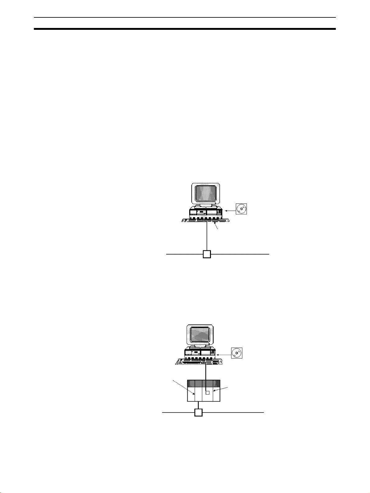
1-1-1 Connecting to the DeviceNet Network
The Configurator is connected to the DeviceNet network using one of the following three methods. The same online functions are supported by all three
methods.
Connection from
Dedicated Board/Card
Installed in Computer
Serial Connection from
COM port of Computer
The computer running the Configurator is connected to the DeviceNet network by installing an OMRON DeviceNet Board in the computer.
WS02-CFDC1-E
Configurator
Dedicated Board, or
Card
DeviceNet Network
The Configurator is treated as a single
DeviceNet node.
The computer running the Configurator is connected to the DeviceNet network by connecting from the COM port of the computer to the serial communications port (peripheral port) of a CS/CJ-series CPU rack containing a CS1WDRM21 or CJ1W-DRM21 DeviceNet Unit.
WS02-CFDC1-E
Configurator
CS/CJ-series
DeviceNet Unit
The Configurator is not treated as a
single DeviceNet node .
COM port
Peripheral bus or Host Link
Peripheral or RS-232C port of
CPU Unit or RS-232C port of
Communications Board/Unit
DeviceNet network
2
Page 22
Introduction Section 1-1
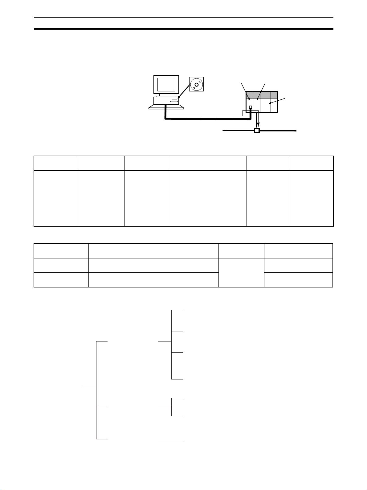
Ethernet Connection The computer running the Configurator is connected to the DeviceNet net-
work by connecting from the Ethernet port of the computer to a CS/CJ-series
Ethernet Unit.
WS02-CFDC1-E
Configurator
Ethernet port
CS/CJ-series
Ethernet Unit
CS/CJ-series
DeviceNet Unit
CPU Unit
Ethernet
1-1-2 Models
Product Model Contents Method of connecting to
DeviceNet network
Configurator
(Ver. 2.@)
WS02-CFDC1-E Installation disk
(CD-ROM)
Either one of the following
methods
• Dedicated Board/Card (See
note.)
• Serial connection from COM
port of computer
• Ethernet connection from
Ethernet port of computer
Note Use the following dedicated Boards and Card.
Model Contents Personal
3G8E2-DRM21-EV1 Dedicated PCMCIA Card and Configurator
3G8F5-DRM21-E Dedicated ISA Board and Configurator (Ver. 2.@)
(Ver. 2.@) installation disk
installation disk
1-1-3 Overview
IBM PC/AT or
compatible
computer
IBM PC/AT or
compatible
DeviceNet network
Personal
Applicable OS
computer
Windows 95,
98, Me, 2000,
NT4.0 or XP
Applicable OS
Windows 95, 98, Me,
2000 or XP
Windows 95, 98 or NT4.0
Main functions of
Configurator
Setup functions
Monitoring functions
Storage functions
Remote I/O master user-set allocations (with creation of a scan
list) and remote I/O slave user-set allocations
Enabling or disabling master or slave function of CS/CJ-series
DeviceNet Unit.
Setting master device parameters except scan list parameters
(i.e., connection settings, device data checks, and
communications cycle time)
Setting other manufacturers' slave and master device
parameters
Displaying a device information list
Monitoring multistatus, Unit status, Master error logs, and
communications cycle data
Saving offline device information prepared with master device
parameters or online network device information (Data is saved
as network configuration files
.)
3
Page 23

Introduction Section 1-1
Note Master device parameters used in a scan list are created with either of the fol-
lowing methods.
a) Using the Parameter Wizard
b) Setting all parameters
1-1-4 Configurator Specifications
Item Specification
Operating
environment
Network connection method Dedicated Board/Card 3G8F5-DRM21-E: Dedicated ISA Board
Node address
used
Connectable number of Boards/
Cards
DeviceNet masters OMRON CS1W-DRM21, CJ1W-DRM21, CVM1-DRM21-V1, or C200HW-DRM21-V1
Hardware Personal computer: IBM PC/AT or compatible
CPU: Pentium 166 MHz or higher
Memory: 32 Mbytes
Hard disk: A minimum of 15 Mbytes
OS Windows 95, 98, Me, NT4.0, 2000, or XP
Dedicated
Board/Card
Serial
connection
(Some limitations exist for the Dedicated Boards.)
3G8E2-DRM21-EV1: Dedicated PCMCIA Card
Serial connection Connect from the COM port of the computer to the
DeviceNet network, via the following serial communications port (Toolbus or Host Link) on a CS/CJ-series
PLC.
• Peripheral port of CPU Unit
• RS-232C port of CPU Unit
• RS-232C port of Serial Communications Board/Unit
Note The CS/CJ-series DeviceNet Unit (CS1W-
DRM21 or CJ1W-DRM21) is necessary to connect to the DeviceNet network using serial
communications.
Ethernet connection Connect from the Ethernet port of the computer to the
DeviceNet network, via an Ethernet Unit for a CS/CJseries PLC.
Note The CS/CJ-series Ethernet Unit (CS1W-
ETN@@ or CJ1W-ETN@@) and CS/CJ-series
DeviceNet Unit (CS1W-DRM21 or CJ1WDRM21) are necessary to connect to the
DeviceNet network using Ethernet.
A single node address is used.
No node address is used.
One/network
Note Device parameters of OMRON DeviceNet Units are output in the DRM_UNIT
file format for open network controllers or the NX-Server file format for the
DeviceNet.
4
Page 24

Introduction Section 1-1
Item Specification
Main functions Setup functions Master device parameter settings for OMRON’s Master
• Remote I/O master user-set allocations (with a scan list)
The node address order can be set as desired. Two output blocks and two input
blocks can be allocated. (See note.)
• Remote I/O slave user-set allocations
• Setting master remote I/O communications connections.
• Setting slave remote I/O communications connections.
• Enabling or disabling device data checks through remote I/O communications
(checks on slave vendor, device type, and product code data).
• Setting an explicit message monitor timer list.
• Setting a COS/cyclic heart beat timer value.
• Setting the communications cycle time.
Note 1. A device Parameter Wizard is supported for the Master.
2. Using remote I/O master user-set allocations eliminates restrictions on
node addresses. Furthermore, a number of masters can be mounted to
the PLC with no allocation area duplication.
Setting parameters for slaves (including other manufacturers’ slaves).
Setting node addresses and baud rates.
Setting I/O comments (for slave I/O data).
Monitoring
functions
Storage
functions
File export
functions
Other functions • Reading/preparing EDS files.
• Listing information on devices connected to the network (in node address order or
remote I/O configuration order, for example).
• Monitoring status of OMRON Master Unit.
• Monitoring error history of OMRON Master Unit (time, error code, and error condition).
• Monitoring communications cycle time.
• Monitoring slave status and parameters.
• Saving the parameters of devices connected to the network as network configuration
files.
• Saving the parameters of each device, in device units, as device parameter files.
• Exporting the network configuration list (contents displayed in the Detailed Display
Mode) in the CSV file format.
• Exporting I/O comments in CSV file format.
• Device parameters of OMRON’s Master Units are exported in the DRM_UNIT (virtual unit) file format for open network controllers.
• Device parameters of OMRON’s Master Units are exported in the NX-Server file format for the DeviceNet.
• Printing master/slave device parameters.
• Setting/reading parameters with explicit messages.
Note To use the Configurator to construct a DeviceNet network or make master or
slave settings, the EDS file is required. If other manufacturers’ slaves are
used, obtain the correct EDS files.
1-1-5 Files Created with Configurator
It is possible to create the following files with the Configurator.
Files Description Extension
Network configuration
files
Device parameter files Parameters for each device (master or
EDS files A common device definition file on the
The parameter file for all devices (master
and slave devices) on a single virtual
network (Network Configuration Window)
slave)
DeviceNet network
.npf
.dvf
.eds
5
Page 25

Introduction Section 1-1
Note In addition, files can be exported and saved in the following formats.
• The network configuration (contents displayed in the Detailed Display
Mode) can be saved in the CSV file format.
• I/O comments can be exported to a CSV file
• Device parameters of OMRON Master Units can be saved in the
DRM_UNIT (virtual unit) file format for open network controllers.
• Device parameters of OMRON Master Units can be saved in the NX-
Server file format for the DeviceNet.
1-1-6 Importing Version 1 Configurator Files
Version 2 of the Configurator can import files created with version 1 of the
Configurator.
Files Description Extension
Network configuration
files
Master parameter files Parameters for each master device .dsf
Slave parameter files Parameters for each slave device .dpf
The parameter file for all devices (master
and slave devices) on a single virtual
network (Network Configuration Window).
.ntf
1-1-7 Functions of the Configurator
The DeviceNet Configurator has 2 modes: Online and offline.
Online: The Configurator is connected to the DeviceNet network for net-
work communications.
Offline: The Configurator is not connected to the DeviceNet network.
The Configurator has the following functions that allow the user to design, set
up, and control the DeviceNet network.
Windows 95, 98, Me,
NT4.0, 2000, or XP
Compatibility
Graphic Displays The Configurator has Windows-style displays that are easy to understand and
Network Management The Configurator constructs a virtual network in the Network Configuration
The Configurator will operate under the Windows operating systems.
Other applications can be run simultaneously while monitoring the DeviceNet
network’s status.
Note The ISA Board is compatible with Windows 95, 98, and NT4.0 only.
The PCMCIA Card is compatible with Windows 95, 98, Me, 2000, and XP
only.
easy to use.
Required master and slave settings are made just by selecting the icons. It is
not necessary to input complicated commands. Even a beginner can make
settings and monitor operation with ease.
Window and adds necessary devices to the network. The construction of the
network is thus possible offline.
It is possible for the virtual network (i.e., the Network Configuration Window)
to read the network configuration from a file or actual network.
Furthermore, the network configuration can be downloaded from the virtual
network (i.e., the Network Configuration Window) and all settings can be registered with actual devices.
Online Connections to
DeviceNet Network
6
The online functions of the Configurator are executed by connecting the Configurator to the DeviceNet network through a dedicated Board or Card. (In that
case, the Configurator will be treated as a single node on the DeviceNet network.)
Page 26

Introduction Section 1-1
Connection can also be made from the COM port of the computer to the serial
communications port of a CS/CJ-series CPU Unit (or the Serial Communications Board/Unit) via Toolbus or Host Link. In this case, a CS/CJ-series
DeviceNet Unit (CS1W-DRM21 or CJ1W-DRM21) is necessary for connection
to the DeviceNet network.
Similarly, connection can be made from the Ethernet port of the computer via
a CS/CJ-series Ethernet Unit. In this case also, a CS/CJ-series DeviceNet
Unit (CS1W-DRM21 or CJ1W-DRM21) is necessary for connection to the
DeviceNet network.
Device Settings The following parameter settings are for other manufacturers’ slaves as well
as OMRON’s master and slave devices.
A comment can be added to the I/O data of each device.
Setting Description CS1W-DRM21 C200HW-DRM21-V1
Master functions enable/disable
I/O allocations Slaves are allocated to the master in the desired
Communication cycle time Sets the communication cycle time.
Connection setting During remote I/O communications, the user can
Device data check Determines whether slave device data items
Slave functions enable/disable
Slave functions I/O allocation I/O allocations can be made for slaves of the
Remote I/O
communications startup
Explicit message communications set/reset
Enables or disables the master functions for
remote I/O communications.
areas and order.
If the I/O allocations are simple, the Parameter
Wizard can be used to allocate I/O very easily.
I/O allocations are possible as well by just drag-
ging and dropping the slave to the allocation
area.
(The interval for I/O communications with
slaves.)
make connection settings for up to two connections per slave. Automatic connection settings
can be selected as well.
(i.e., the vendor, device type, and product code)
are checked during remote I/O communications.
Enables or disables the slave functions for
remote I/O communications.
CS1-series DeviceNet Unit. (I/O can be
allocated freely.)
Determines whether or not to start remote I/O
communications when the master is started.
Setting or resetting the function to enable explicit
message communications without remote I/O
communications.
and
CVM1-DRM21-V1
Ye s N o
Ye s Ye s
Ye s Ye s
Ye s N o
Ye s N o
Ye s N o
Ye s N o
(See note 1.) Yes
(See note 2.) Yes
Note 1. The same function can be achieved with the master functions enable/dis-
able setting.
2. When not registered in the scan list, explicit message communications are
possible without remote I/O communications.
Device Monitoring The status, error log, etc., of a device can be monitored, provided that the
device supports the monitor function. The monitor function is supported by
OMRON’s Master Units and some Special Slaves.
7
Page 27

Introduction Section 1-1
Master Status Monitor
The status of the specified OMRON master is displayed. The status of a slave
will be displayed as well if it is in remote I/O communications with the Master.
Slave Status Monitor
The status of the specified MULTIPLE I/O TERMINAL (i.e., DRT1-COM Communications Unit) will be displayed. The configuration of the I/O Unit connected to the Communications Unit will be displayed as well.
Master Error Log Display
The error log in the specified OMRON master can be read, displayed, or
cleared.
Communication Cycle Time Display
The present communication cycle time of the specified OMRON master will
be displayed. The maximum communications cycle time and minimum communications cycle time counted from the moment previous values are
refreshed will be displayed as well. The maximum communications cycle time
and minimum communications cycle time can be reset any time.
8
Page 28
Introduction Section 1-1
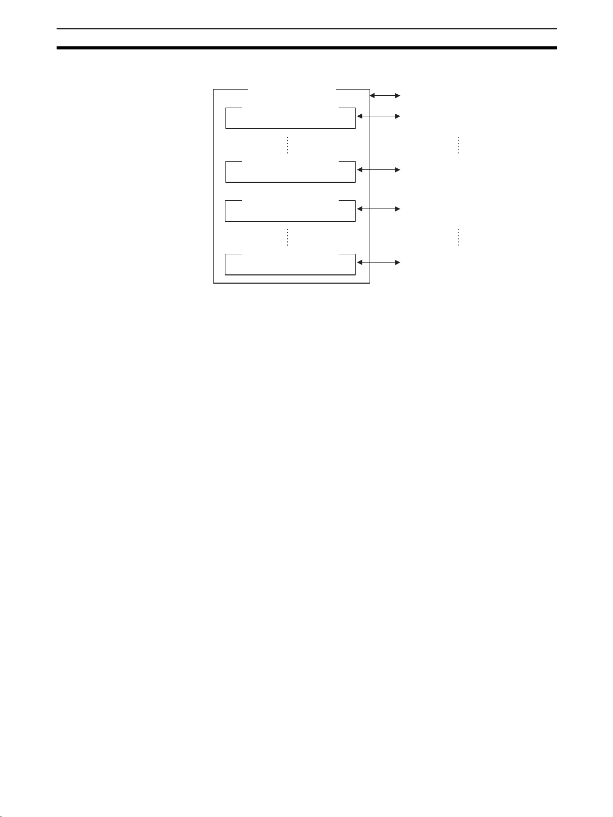
File Management The Configurator saves or loads the following data in files.
Network Configuration
(List of devices)
Master device parameter
Network configuration file
Parameter file of each master device
Device (EDS File)
Management
Master device parameter
Slave device parameter
Slave device parameter
Parameter file of each master device
Parameter file of each slave device
Parameter file of each slave device
• The network configuration file includes the parameters for all devices
(master and slave devices). The parameter file for each master and slave
device contains the individual device parameters. Parameter files can be
managed independently from network configuration files.
• Files from version 1 of the Configurator are not compatible with those of
version 2. Files from version 1 of the Configurator can be read, however,
by using the import function.
Note Device parameter files of the CS-series CS1W-DRM21 DeviceNet Unit are
compatible with Unit setup files that can be backed up in the Memory Card of
the CS1-series CPU Unit.
The construction of a network with the Configurator requires the appropriate
EDS files. Information on each device is obtained from the EDS file.
If no EDS file is provided, use the hardware (EDS file) management function
to install or create an EDS file.
Other Functions DeviceNet vendor definition files, device type definition files, and slave setup
files for the MULTIPLE I/O TERMINALs can be set for the Configurator, with
which additional DeviceNet vendors and device types can be used.
Furthermore, the Expansion Module can be installed so that edit and monitoring functions can be added for other manufacturers’ devices (masters and
slaves) or OMRON devices that will be released in the future.
Note When the dedicated Board is used to connect to the DeviceNet network, the
Configurator will be a single node on the DeviceNet network. Be sure that the
node address of the computer is not duplicated with that of any other node.
9
Page 29

Introduction Section 1-1
1-1-8 Comparison with Previous Versions of the Configurator
The following table lists the difference in function between version 1.20 and
version 2.@ of the Configurator.
Item Version 2.@ Version 1.20
Basic configuration/operations Dragging and dropping offline make
Network connection • Dedicated ISA Board
Supported
DeviceNet
masters
Monitor
functions
Storage
functions
OMRON masters CS1W-DRM21, CJ1W-DRM21,
Slave remote I/O allocations Possible with CS/CJ-series PLCs
Master remote I/O
communications settings
Slave remote I/O
communications settings
Enabling or disabling device
data checks in remote I/O
communication
Explicit message monitoring
timer list settings
COS/Cyclic heart beat timer
settings
I/O comment settings (for
slave I/O data)
Display of list of data on network devices
Unit status monitoring Possible with CS/CJ-series PLCs
Slave function monitoring Possible Impossible
Network configuration files Possible (extension: .npf) Possible (extension: .ntf)
Device parameter files Possible (extension: .dvf) Possible
EDS files Possible (extension: .eds) Impossible
Compact flash memory Stored in compact flash memory and
it possible to create a virtual network
(for display) in the Configurator.
Each device (Master or slave) can
also be set online.
• Dedicated PCMCIA Card
• From the COM port of the computer
to the serial port of the PLC. (Possible with CS/CJ-series PLCs only.)
• From the Ethernet port of the computer to the Ethernet Unit of the
PLC. (Possible with CS/CJ-series
PLCs only.)
CVM1-DRM21-V1 or C200HWDRM21-V1
Note Output is possible in file for-
mats compatible with open
network controllers or NXServers for DeviceNet.
only.
Possible with CS/CJ-series PLCs
only.
Possible with CS/CJ-series PLCs
only.
Possible with CS/CJ-series PLCs
only.
Possible with CS/CJ-series PLCs
only.
Possible with CS/CJ-series PLCs
only.
Possible Impossible
Possible Possible
only.
downloaded to the master. (Possible
with CS/CJ-series PLCs only.)
Each device must be set online,
except the scan list of the master.
• Dedicated ISA Board
• Dedicated PCMCIA Card
CVM1-DRM21-V1 or C200HWDRM21-V1
Note The CS1W-DRM21, open
network controllers, or NXServers for DeviceNet cannot
be used.
Impossible
Impossible
Impossible
Impossible
Impossible
Impossible
Impossible
(master: Extension: .dsf
slave: Extension: .dpf)
Impossible
10
Page 30

Confirming Product Contents Section 1-2
Item Version 2.@ Version 1.20
File export
functions
I/O command output in CCV
file format
Device
parameter of
OMRON
masters
EDS file creation Possible
I/O allocation duplication
check between Masters
Output for
open network
controllers in
DRM_UNIT
file format
Output for NXServers for
DeviceNet in
NX-Server file
format
Possible Impossible
Possible Impossible
Possible Impossible
Device discrimination data and I/O
data files are created. Device parameter data files cannot be created.
Impossible Possible
Conditionally possible
Tentative EDS files (with device
discrimination data only) are
created. Device I/O data or
parameter data files cannot be
created.
1-2 Confirming Product Contents
Please check the contents of your product as soon as if arrives.
Product Contents Quantity
WS02-CFDC1-E
Configurator
3G8F5-DRM21-E
ISA Board
3G8E2-DRM21-EV1
PCMCIA Board
Configurator installation disk
(CD-ROM)
3G8F5/3G8E2 setup disk (driver
setup tool on CD-ROM)
User registration card and software
license
Information 1
Dedicated ISA board 1 (with
Configurator installation disk
(CD-ROM)
3G8F5/3G8E2 setup disk (driver
setup tool on CD-ROM)
User registration card and software
license
Information 1
Dedicated PCMCIA board 1 (with
Configurator installation disk
(CD-ROM)
3G8F5/3G8E2 setup disk (driver
setup tool on CD-ROM)
User registration card and software
license
Information 1
1
1
1
1communications
connector included)
1
1
1
1communications
connector included)
1
1
1
11
Page 31

Operating Environment Section 1-3
1-3 Operating Environment
The Configurator operates in the following environment.
Compatible personal
computer
OS Windows 95, 98, Me, NT4.0, 2000, or XP
CPU Pentium 166 MHz or better
Available hard disk space 15 Mbytes min.
Memory 32 Mbytes min.
CD-ROM drive 1 (used for software installation)
Display VGA or better
Hardware for network
connection
1-3-1 Configurator Precautions
Observe the following precautions when using the Configurator.
• The only DeviceNet masters that can be handled by the Configurator are
OMRON’s CS1W-DRM21, CJ1W-DRM21, CVM1-DRM21-V1, and
C200HW-DRM21-V1.
• When a dedicated Board or Card is used, the Configurator is connected
to the DeviceNet network as a single node. The Configurator cannot be
connected to the network unless a node address is available. No node
address is required if the Configurator is connected via Ethernet or a
serial communications port.
• Do not use the Configurator in a location with too much electromagnetic
noise. If noise is too extreme, the computer may run out-of-control,
although there will be no negative effects on the DeviceNet network even
if noise causes the computer to run out-of-control.
IBM PC/AT or compatible personal computer
One of the following is required for online connection to
the DeviceNet network.
OMRON DeviceNet Board/Card
Dedicated PCMCIA Card (3G8E2-DRM21-EV1)
Dedicated ISA Board (3G8F5-DRM21-E)
Ethernet port
COM port
1-3-2 PCMCIA Card Precautions
• Use the PCMCIA Card Unit on a level surface, as shown in the following
diagram.
• Do not bend or pull the cable that connects the PCMCIA Card and the
PCMCIA Card Unit.
• The PCMCIA Card is a portable peripheral device. Do not leave it connected to the network.
• Attaching ferrite cores between the PCMCIA Card and the PCMCIA Card
Unit can reduce noise from the network.
12
Page 32

Operating Environment Section 1-3
Attach one ferrite core near the Unit and another near the card, as shown
in the following diagram.
Ferrite cores
Ferrite core
We recommend one of the following ferrite cores.
Company:Fair-Rite Products Corp.
Models: 0443-164251
045A-164257
Address: PO Box J, One Commercial Row, Wallkill, NY 12589 USA
Phone: (845) 895-2055
Fax: (845) 895-2629
13
Page 33

Operating Environment Section 1-3
14
Page 34

SECTION 2
Installation
This section explains how to install the ISA Board, PCI Board, or PCMCIA Card hardware in the computer, make the
necessary hardware settings and computer settings, and install the DeviceNet Configurator software in the computer.
2-1 Installation Procedure . . . . . . . . . . . . . . . . . . . . . . . . . . . . . . . . . . . . . . . . . . . 16
2-2 ISA Board Installation . . . . . . . . . . . . . . . . . . . . . . . . . . . . . . . . . . . . . . . . . . 16
2-2-1 Preparation for Installation . . . . . . . . . . . . . . . . . . . . . . . . . . . . . . . . 16
2-2-2 ISA Board Components and Functions . . . . . . . . . . . . . . . . . . . . . . 19
2-2-3 DIP Switch Settings . . . . . . . . . . . . . . . . . . . . . . . . . . . . . . . . . . . . . 19
2-2-4 Installation in the Computer . . . . . . . . . . . . . . . . . . . . . . . . . . . . . . . 20
2-2-5 3G8F5/3G8E2-DRM21 Driver Setup Software Installation. . . . . . . 20
2-3 PCMCIA Card Installation . . . . . . . . . . . . . . . . . . . . . . . . . . . . . . . . . . . . . . . 24
2-3-1 Preparation for Installation . . . . . . . . . . . . . . . . . . . . . . . . . . . . . . . . 24
2-3-2 PCMCIA Card Components and Functions . . . . . . . . . . . . . . . . . . . 25
2-3-3 PCMCIA Card Setup . . . . . . . . . . . . . . . . . . . . . . . . . . . . . . . . . . . . 25
2-3-4 3G8F5/3G8E2-DRM21 Driver Setup Software Installation. . . . . . . 28
2-4 Configurator Installation. . . . . . . . . . . . . . . . . . . . . . . . . . . . . . . . . . . . . . . . . 32
15
Page 35

Installation Procedure Section 2-1
2-1 Installation Procedure
The following flowchart shows the steps involved in installing the Configurator.
When only designing
the network
(When creating a
settings file offline)
Connecting
with a
PCMCIA Card
Install the
PCMCIA Card
2-2 ISA Board Installation
This section explains how to set the dedicated ISA Board used by the Configurator and install the Board in the computer.
When connecting to the network
to make settings or monitor.
(When using online)
Connecting
with an ISA
Board
Install the
ISA Board
Install the driver
setup tool
Install the
Configurator
Connecting
via Ethernet
Connecting
by COM
port
2-2-1 Preparation for Installation
The dedicated ISA Board used by the Configurator is not a plug-and-play
board. Before installing the Board, check the items listed in the following table.
Item Description
Windows OS Verify that the OS is Windows 95, 98, or NT4.0.
Unused expansion slot Verify that there is an unused expansion slot (ISA slot) in
Available memory The ISA Board for the Configurator occupies 16 KB of
Unused I/O port address The ISA Board for the Configurator occupies 8 port
Note The dedicated ISA Board used by the Configurator cannot be used with Win-
dows Me, 2000, or XP.
Windows 95/98
Procedure
When Windows 95/98 is being used, follow this procedure to verify the available memory and I/O port addresses and reserve these addresses for the
Configurator’s ISA Board.
the computer.
memory between the memory range of C0000 and
DFFFF as a system resource.
Verify that the computer has 16 KB of available memory
between the memory range of C0000 and DFFFF and
select a leading address. The leading address is needed
during the driver installation.
addresses between the memory range of 200 and 2FF as
a system resource.
Verify that the computer has 8 addresses available and
select a leading I/O address. The leading I/O address is
needed when setting the ISA Board’s DIP switch.
16
Page 36

ISA Board Installation Section 2-2
1,2,3... 1. Click the Start Button and select Control Panel from the Settings Menu.
2. Double-click the System Icon in the Control Panel Window.
3. Select the Device Manager Tab from the System Properties Window.
4. Select Computer and click the Properties Button at the bottom of the win-
dow.
5. Select the View Resources Tab.
6. Select Input/output (I/O) from the View Resources Page and click the OK
Button. The current I/O port allocations will be displayed. Find an unused
I/O port address that can be used for the ISA Board.
17
Page 37

ISA Board Installation Section 2-2
7. Select the Reserve Resources Tab.
8. Selecting Input/output (I/O) from the Reserve Resources Page, click the
Add Button, and register the range of I/O port addresses for the ISA Board
as shown in the following diagram.
In this example, I/O port addresses 250 through 257 (hexadecimal) are reserved.
Windows NT 4.0
Procedure
18
9. Follow the same procedure in steps 5 to 8 to reserve 16-Kbytes of memory.
10. Click the OK Button at the bottom of the Computer Properties Window to
accept the changes and close the window. A pop-up window will appear;
restart the computer as required.
When Windows NT 4.0 is being used, the operating system does not monitor
the status of memory and I/O port addresses. Refer to the user’s manuals for
the computer and peripheral devices being used and locate an unused
address for the Configurator’s ISA Board.
Page 38

ISA Board Installation Section 2-2
2-2-2 ISA Board Components and Functions
The following diagram shows the main components of the Configurator’s ISA
Board and their functions.
ISA Bus Connector
Connect to the computer's
ISA slot.
DIP Switch
Sets the I/O port address
which the ISA Board will use.
DeviceNet Communications Connector
Connects to the DeviceNet
communications cable.
2-2-3 DIP Switch Settings
Before connecting the ISA Board to the computer, set the I/O port address
that the Board will use with the Board’s DIP switch.
!Caution Do not touch the ISA Boards connectors or components. Take precautions
against static electricity when handling the ISA Board.
Set the I/O port address with the DIP switch as shown in the following table.
Be sure to set addresses that aren’t being used by another device in order to
avoid a conflict. (A pin setting of 0 is OFF and 1 is ON.)
I/O port addresses
(Hexadecimal)
200 to 207 0 0 0 0 0 0 Used for the game port.
208 to 20F 1 0 0 0 0 0 ---
210 to 217 0 1 0 0 0 0 ---
218 to 21F 1 1 0 0 0 0 ---
220 to 227 0 0 1 0 0 0 ---
228 to 22F 1 0 1 0 0 0 ---
230 to 237 0 1 1 0 0 0 ---
238 to 23F 1 1 1 0 0 0 ---
240 to 247 0 0 0 1 0 0 ---
248 to 24F 1 0 0 1 0 0 ---
250 to 257 0 1 0 1 0 0 Factory default setting.
258 to 25F 1 1 0 1 0 0 ---
LED Indicators
Indicate the status of the ISA Board
and the DeviceNet network.
DIP switch pin settings Remarks
123456
19
Page 39

ISA Board Installation Section 2-2
I/O port addresses
(Hexadecimal)
260 to 267 0 0 1 1 0 0 ---
268 to 26F 1 0 1 1 0 0 ---
270 to 277 0 1 1 1 0 0 ---
278 to 27F 1 1 1 1 0 0 Used for LPT2.
280 to 287 0 0 0 0 1 0 ---
288 to 28F 1 0 0 0 1 0 ---
290 to 297 0 1 0 0 1 0 ---
298 to 29F 1 1 0 0 1 0 ---
2A0 to 2A7 0 0 1 0 1 0 ---
2A8 to 2AF 1 0 1 0 1 0 ---
2B0 to 2B7 0 1 1 0 1 0 ---
2B8 to 2BF 1 1 1 0 1 0 ---
2C0 to 2C7 0 0 0 1 1 0 ---
2C8 to 2CF 1 0 0 1 1 0 ---
2D0 to 2D7 0 1 0 1 1 0 ---
2D8 to 2DF 1 1 0 1 1 0 ---
2E0 to 2E7 0 0 1 1 1 0 ---
2E8 to 2EF 1 0 1 1 1 0 Used for COM port 4.
2F0 to 2F7 0 1 1 1 1 0 ---
2F8 to 2FF 1 1 1 1 1 0 Used for COM port 2.
DIP switch pin settings Remarks
123456
Note There are some boards marketed that cannot distinguish between I/O port
addresses 200 through 2FF and addresses 600 through 6FF. If one of these
boards is allocated address 2@@, it will occupy address 6@@ as well. To avoid
any possible conflicts when assigning an address between 600 and 6FF, be
sure to assign an address that corresponds to an unused address between
200 and 2FF. (For example if 6A0 to 6A7 are selected, make sure that 2A0 to
2A7 are unused.)
2-2-4 Installation in the Computer
The ISA Board must be installed into one of the computer’s expansion slots
(ISA slots). When installing the Board, turn OFF the computer’s power and
take precautions against static electricity. Refer to the computer’s user’s manual for detailed installation procedures.
If there are no problems with the I/O port settings, the computer should recognize the ISA Board when the computer is turned ON and the ISA Board should be usable. If the ISA Board has been installed successfully, proceed to 2-2-5 3G8F5/3G8E2-DRM21 Driver Setup Software Installation.
2-2-5 3G8F5/3G8E2-DRM21 Driver Setup Software Installation
The operations and displays shown in the following procedure may differ
slightly depending on the version of Windows software being used. The displays for Windows 98 are shown here.
1,2,3... 1. Exit all other Windows-based programs.
2. Insert 3G8F5/3G8E2-DRM21 setup disk into the CD-ROM drive.
3. Double-click Setup.exe.
The 3G8F5/3G8E2-DRM21’s setup program will start.
20
Page 40

ISA Board Installation Section 2-2
The following window will be displayed when the setup program has been
loaded. Click the Next Button after reading the precautions.
4. Specify the destination directory for the driver files. If the default directory
shown in the window is acceptable, click the Next Button. To specify a different directory, click the Browse Button, specify the desired directory, and
click the Next Button. If a new directory is specified, the software will create
it automatically.
21
Page 41
ISA Board Installation Section 2-2
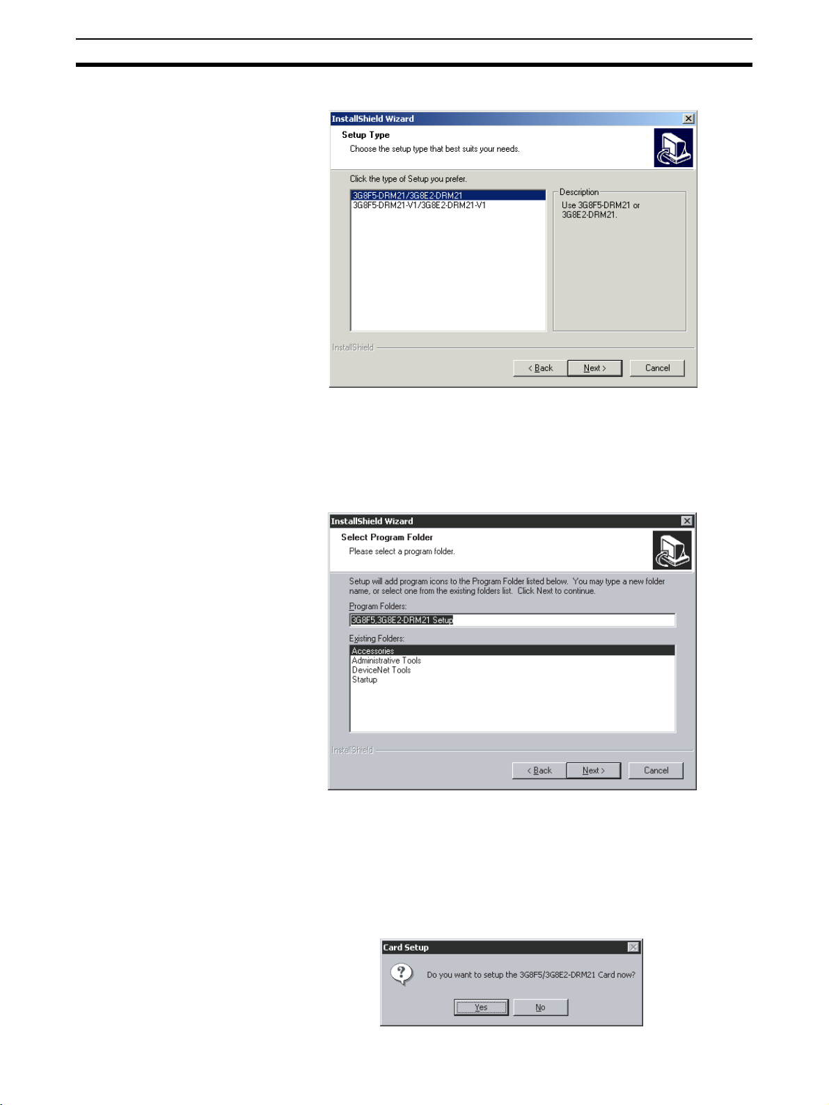
5. Select 3G8F5-DRM21/3G8E2-DRM21.
6. Specify the name of the 3G8F5/3G8E2-DRM21 program folder where the
Software icons will be registered. If the default program folder is acceptable, click the Next Button. To specify a different folder, select an existing
folder or enter a new folder name and then click the Next Button.
Note The program folder name specified here will be registered under De-
viceNet Tools in the Start Menu.
22
7. The installation program will be started and the 3G8F5/3G8E2-DRM21
files will be copied to the destination directory.
8. A program group folder will be created automatically when the 3G8F5/
3G8E2-DRM21 Driver Setup Software installation has been completed.
9. A pop-up window will be displayed asking whether you want to setup the
device driver. If you click the No Button, the installation program will end
without performing the setup for the ISA Board or PCMCIA Card.
Page 42

ISA Board Installation Section 2-2
Note The setup for the ISA Board or PCMCIA Card can be performed later
by clicking the Start Button, then selecting Program, DeviceNet
Tools, 3G8F5/3G8E2-DRM21 Setup, 3G8F5/3G8E2-DRM21-Setup.
10. The setup program for the device driver will start. There is already a card
driver registered, so click the Edit Button. The New selection is used to add
a driver for the ISA Board or PCMCIA Card.
The Remove selection is used to delete the selected driver.
Note a) The card name that is displayed first depends on the operating en-
vironment.
b) The card name registered here will be used on the Configurator to
access the ISA Board or PCMCIA Card.
c) Register a name for each ISA Board and PCMCIA Card.
11. Set the I/O port address, memory address, and interrupt (IRQ) for the ISA
Board or PCMCIA Card being used with the Configurator. (Refer to the
screen in step 12. )
12. Input the I/O port address set on the board’s DIP switch and input a memory address that is available in the computer. Set the interrupt to None.
The Card Name and Driver Name can be changed if necessary.
Make sure that all of the settings are correct and click the OK Button. The
Configuration Window shown in step 10 will be displayed.
Note a) The Configurator does not use interrupts. Set the interrupt level to
None.
b) Do not select -V1 Type in the above Card Setup Dialog Box when
using an ISA Board.
23
Page 43

PCMCIA Card Installation Section 2-3
13. Click the OK Button to exit the setup program.
With Windows 95/98, the Configurator can be run immediately. Click the
OK Button to start the Configurator. With Windows NT, a pop-up window
will be displayed asking whether or not to restart Windows.
14. This completes installation of the 3G8F5-DRM21-E Driver Setup Software.
2-3 PCMCIA Card Installation
This section explains how to set the PCMCIA Card used by the Configurator
and install the card in the computer.
2-3-1 Preparation for Installation
Before installing the PCMCIA Card, check the items listed in the following
table.
Item Description
Windows OS Verify that the OS is Windows 95, 98, Me, 2000, or XP. The PCMCIA Card can only be used in this
environment.
Unused card slot Verify that there is an unused card slot (type II) in the computer.
Available memory The PCMCIA Card used by the Configurator
Unused I/O port
address
occupies 16 KB of memory as a system
resource. Verify that the computer has 16 KB of
available memory.
The PCMCIA card used by the Configurator
occupies 3 ports as a system resource. Verify
that the computer has 3 I/O port addresses
available.
Note The 3G8E2-DRM21-EV1 PCMCIA Card for the Configurator can’t be used
with the Windows NT4.0 operating system.
The PCMCIA Card memory and I/O port combinations used by the Configurator are set automatically by the Windows 95/97 Plug & Play
feature. Use one of the automatically set combinations.
24
Page 44

PCMCIA Card Installation Section 2-3
2-3-2 PCMCIA Card Components and Functions
The following diagram shows the main components of the Configurator’s
PCMCIA Card (Card and Unit sections) and their functions.
Unit section
This section controls DeviceNet
communications.
MS LED
NS LED
LED Indicators
Indicate the status of the PCMCIA
Card and the DeviceNet networ
Card section
This section is inserted into the
computer's card slot.
k.
2-3-3 PCMCIA Card Setup
The operations and displays shown in the following procedure may differ
slightly depending on the version of Windows software being used. Use the
following procedure for setup.
Before Starting the Setup Before starting the setup procedure, remove any PCMCIA Cards (including
those used by the Configurator) that are currently being used. Since the PCMCIA Card can’t be used temporarily during the setup, it may not be possible to
continue the setup operation midway through the operation.
PCMCIA Card Setup
1,2,3... 1. Insert the 3G8F5/3G8E2-DRM21 setup disk into the CD-ROM drive.
2. Install the PCMCIA Card when the Windows system is active. The PCMCIA Card will be recognized as new hardware and the Add New Hardware
Wizard Window will be displayed. Click the Next Button.
25
Page 45

PCMCIA Card Installation Section 2-3
3. Select Search for the best driver for your device as the driver search
method, then click the Next Button.
4. Select CD-ROM drive as the driver location to be searched, then click the
Next Button.
26
5. The driver file will be recognized as shown below. Click the Next Button to
install the driver.
Page 46

PCMCIA Card Installation Section 2-3
6. After the driver has been installed, click the Finish Button.
Verifying Driver Resources
1,2,3... 1. Check that the driver has been installed correctly, as follows:
Click the Start Button, select Control Panel from the Settings Menu, double-click the System Icon in the Control Panel, and select the Device Man-
ager Tab from the top of the System Properties Window (refer to page 24).
Check that SST Device has been added. Then click the + to the left of SST
Devices to check that the PCMCIA Card driver 3G8E2-DRM21-V1 or
5136-DNP-PCM(n) (where n is the PCMCIA slot number) is displayed and
that x or ! is not displayed next to it.
2. Verify the resources currently being used, as follows:
Double-click 3G8E2-DRM21-V1 or 5136-DNP-PCM(n) to display the
3G8E2-DRM21-V1 or 5136-DN-PCM(n) Properties Window and select the
27
Page 47

PCMCIA Card Installation Section 2-3
Resources Tab from the top of the window. The automatically set Input/
Output Range and Memory Range values will be displayed.
This completes installation of the PCMCIA Card driver. Write down the values of Input/Output Range and Memory Range because these will be
needed later when installing the Configurator.
2-3-4 3G8F5/3G8E2-DRM21 Driver Setup Software Installation
The operations and displays shown in the following procedure may differ
slightly depending on the version of Windows software being used. The displays for Windows 98 are shown here.
1,2,3... 1. Exit all other Windows-based programs.
2. Insert 3G8F5/3G8E2-DRM21 setup disk into the CD-ROM drive.
3. Double-click Setup.exe.
The 3G8F5/3G8E2-DRM21’s setup program will start.
The following window will be displayed when the setup program has been
loaded. Click the Next Button after reading the precautions.
28
Page 48

PCMCIA Card Installation Section 2-3
4. Specify the destination directory for the driver files. If the default directory
shown in the window is acceptable, click the Next Button. To specify a different directory, click the Browse Button, specify the desired directory, and
click the Next Button. If a new directory is specified, the software will create
it automatically.
5. Select 3G8F5-DRM21-V1/3G8E2-DRM21-V1.
6. Specify the name of the 3G8F5/3G8E2-DRM21 program folder where the
Software icons will be registered. If the default program folder is acceptable, click the Next Button. To specify a different folder, select an existing
folder or enter a new folder name and then click the Next Button.
29
Page 49

PCMCIA Card Installation Section 2-3
Note The program folder name specified here will be registered under De-
viceNet Tools in the Start Menu.
7. The installation program will be started and the 3G8F5/3G8E2-DRM21
files will be copied to the destination directory.
8. A program group folder will be created automatically when the 3G8F5/
3G8E2-DRM21 Driver Setup Software installation has been completed.
9. A pop-up window will be displayed asking whether you want to setup the
ISA Board or PCMCIA Card. Click the Yes Button. If you click the No But-
ton, the installation program will end without performing the setup for the
ISA Board or PCMCIA Card.
30
Note The setup for the ISA Board or PCMCIA Card can be performed later
by clicking the Start Button, then selecting Program, DeviceNet
Tools, 3G8F5/3G8E2-DRM21 Setup, 3G8F5/3G8E2-DRM21-Setup.
10. The setup program for the device driver will start. There is already a card
driver registered, so click the Edit Button. The New selection is used to add
a driver for the ISA Board or PCMCIA Card.
Page 50

PCMCIA Card Installation Section 2-3
The Remove selection is used to delete the selected driver.
Note a) The card name that is displayed first depends on the operating en-
vironment.
b) The card name registered here will be used on the Configurator to
access the ISA Board or PCMCIA Card.
c) Register a name for each ISA Board and PCMCIA Card.
11. Set the I/O port address, memory address, and interrupt (IRQ) for the ISA
Board or PCMCIA Card being used with the Configurator. (Refer to the
screen in step 12. )
12. Input the values that were confirmed in the PCMCIA Card setup for the I/
O Port, Memory Address, and Interrupt (IRQ).
Select -V1 Type in the Card Setup Dialog Box shown below when using the
3G8E2-DRM21-EV1.
The Card Name and Driver Name can be changed if necessary.
Make sure that all of the settings are correct and click the OK Button. The
Configuration Window shown in step 10 will be displayed.
Note The Configurator does not use interrupts. Set the interrupt level to
None.
31
Page 51
Configurator Installation Section 2-4
13. Click the OK Button to exit the setup program.
With Windows NT, a pop-up window will be displayed asking whether or
not to restart Windows.
14. This completes installation of the 3G8E2-DRM21-EV1 Driver Setup Software.
2-4 Configurator Installation
This section explains how to install the Configurator. The Configurator is
installed by executing the setup program of the Configurator.
Preparation for
Installation
Installation The operations and displays shown in the following procedure may differ
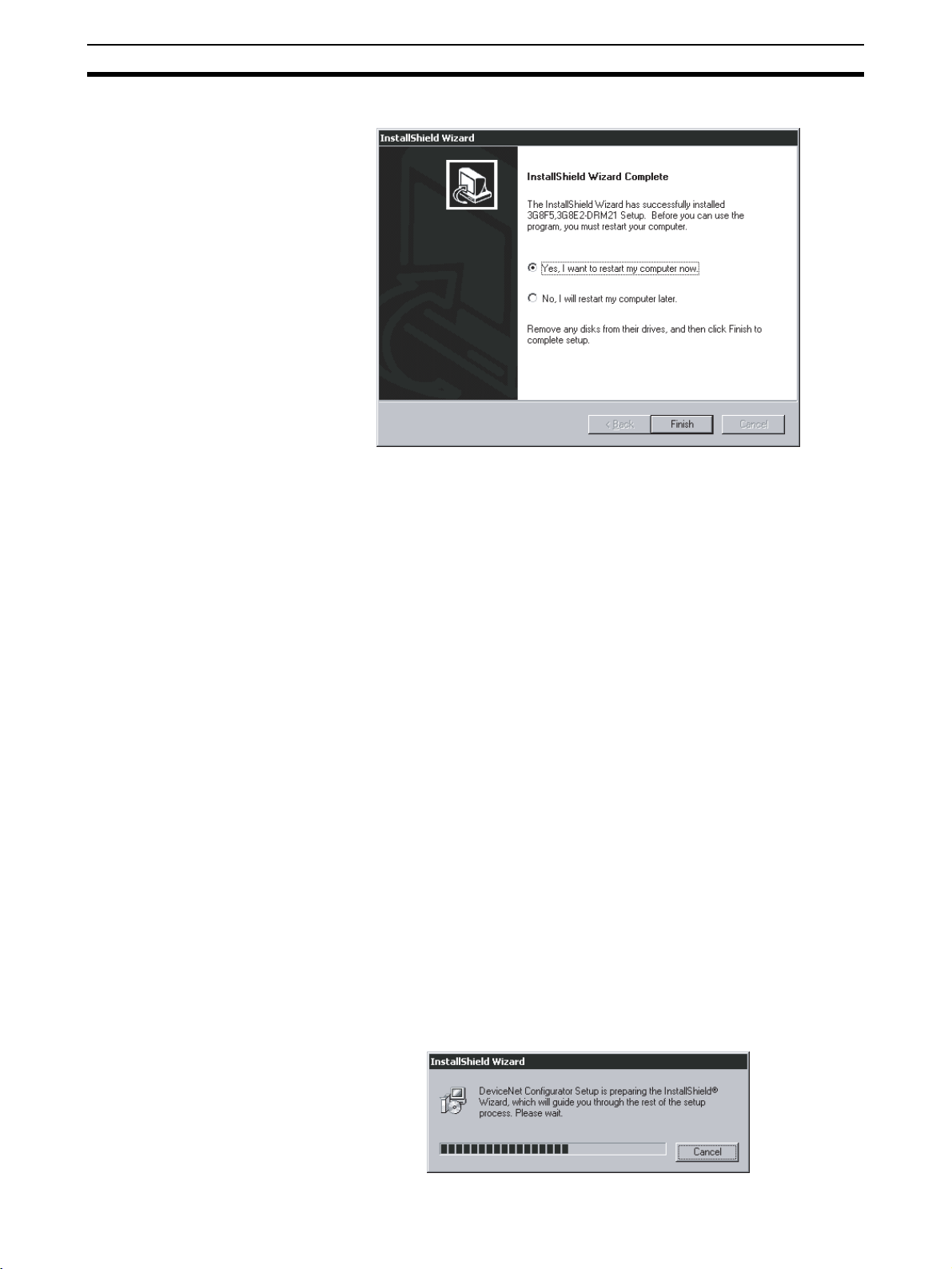
1,2,3... 1. Exit all other Windows-based programs.
Prior to upgrading to a newer Configuration version, be sure to uninstall the
previous Configuration version. (Uninstalling is not necessary, however, when
the update module is used.)
If the update module was used to upgrade in the past, the update module
must also be uninstalled.
When upgrading from a Ver. 1.@ Configurator to a Ver. 2.@ Configurator,
install the driver setup tool first after uninstalling the Ver. 1.@ Configurator.
Note Select Settings, Control Panel, and Add/Remove Programs from the Start
Menu for uninstalling.
slightly depending on the version of Windows software being used. The displays for Windows 98 are shown here.
2. Insert the setup disk (CD-ROM) into the CD-ROM drive.
3. Double-click Setup.exe.
The setup program of the Configurator will start. A pop-up window will indicate the progress of the setup as the program is loaded.
32
Page 52

Configurator Installation Section 2-4
4. The following window will be displayed when the setup program has been
loaded. Click the Next Button after reading the precautions.
5. The license agreement will be displayed.
Read the license agreement. Click the Ye s Button if you agree to all the
contents. If No Button is selected, the setup procedure will be canceled.
6. Specify the destination directory for the Configurator files. If the default directory shown in the window is acceptable, click the Next Button. To specify a different directory, click the Browse Button, specify the desired
33
Page 53

Configurator Installation Section 2-4
directory, and click the Next Button. If a new directory is specified, the software will create it automatically.
7. Specify the name of the interface to be used.
If the default interface is acceptable, click the Next Button.
34
8. The installation program will be started and the Configurator files will be
copied to the destination directory. If the default program folder is acceptable, click the Next Button. To specify a different folder, select an existing
folder or enter a new folder name and then click the Next Button.
Page 54

Configurator Installation Section 2-4
Note The program folder name specified here will be registered under De-
viceNet Tools in the Start Menu.
9. The installation program will be started and the Configurator files will be
copied to the destination directory.
35
Page 55

Configurator Installation Section 2-4
10. The following window will be displayed when the installation of the Configurator completes.
11. Click the OK Button to exit the setup program.
This completes installation of the Configurator.
36
Page 56

This section explains the basic operation of the DeviceNet Configurator.
3-1 Starting the Configurator and the Main Window . . . . . . . . . . . . . . . . . . . . . . 38
3-1-1 Hardware List . . . . . . . . . . . . . . . . . . . . . . . . . . . . . . . . . . . . . . . . . . 39
3-1-2 Network Configuration Window . . . . . . . . . . . . . . . . . . . . . . . . . . . 40
3-2 Menu Commands . . . . . . . . . . . . . . . . . . . . . . . . . . . . . . . . . . . . . . . . . . . . . . 41
3-2-1 Main Menu . . . . . . . . . . . . . . . . . . . . . . . . . . . . . . . . . . . . . . . . . . . . 41
3-2-2 Tool Bar Icons. . . . . . . . . . . . . . . . . . . . . . . . . . . . . . . . . . . . . . . . . . 44
3-2-3 Status Bar . . . . . . . . . . . . . . . . . . . . . . . . . . . . . . . . . . . . . . . . . . . . . 45
3-3 Connecting to the Network . . . . . . . . . . . . . . . . . . . . . . . . . . . . . . . . . . . . . . . 46
3-3-1 Connecting to the DeviceNet Network. . . . . . . . . . . . . . . . . . . . . . . 46
3-3-2 Designating the Interface . . . . . . . . . . . . . . . . . . . . . . . . . . . . . . . . . 47
3-4 Operation Flowcharts . . . . . . . . . . . . . . . . . . . . . . . . . . . . . . . . . . . . . . . . . . . 58
3-4-1 Offline Operation . . . . . . . . . . . . . . . . . . . . . . . . . . . . . . . . . . . . . . . 58
3-4-2 Downloading Saved Parameters . . . . . . . . . . . . . . . . . . . . . . . . . . . . 58
3-4-3 Saving the Parameters for the Entire Existing Network . . . . . . . . . . 58
SECTION 3
Basic Operation
37
Page 57

Starting the Configurator and the Main Window Section 3-1
3-1 Starting the Configurator and the Main Window
Select Program, DeviceNet Tools, and DeviceNet Configurator, from the
Start Menu if the default program folder name is used. The Configurator will
start and the following Main Window will be displayed.
The following description provides information on the Main Window of the
Configurator.
The Main Window consists of the hardware list and Network Configuration
Window.
Hardware list
A list of devices that can
be added to the network.
Network Configuration Window
A virtual network.
38
Page 58
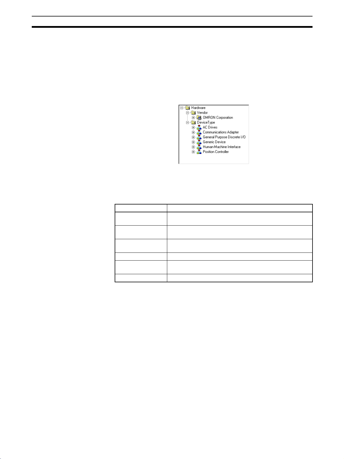
Starting the Configurator and the Main Window Section 3-1
3-1-1 Hardware List
The hardware list shows the devices in which EDS files have been installed.
To simplify searching, it is divided into Vendor and Device Type groups.
The same devices are found in each of these groups, and can be selected
from whichever one is easiest to search.
Devices can be added to the network by selecting them from the hardware list
and dragging them into the Network Configuration Window.
Vendor Group When the Configurator is first installed, the Vendor group contains only
OMRON hardware. If products (containing EDS files) from other manufacturers are installed, their list will automatically be built.
Device Type Group The Device Type group consists of the following types of devices.
Device type Description
General Purpose
Discrete I/O
Communications
Adapter
Human-Machine
Interface
AC Drives These devices are AC drives.
Position Controller These are devices with positioning functions, such as servo-
Generic Device These are other devices.
General-purpose I/O devices.
These devices serve as a network gateway.
These devices function as human-machine interfaces.
motors and stepping motors.
Devices will not be displayed in the hardware list unless they have had an
EDS file installed.
Note The hardware list can be moved left/right and up/down, removed for use as a
separate window, or closed.
• To move or remove for use as a separate window
Drag the top of the hardware list to move it. To remove it for use as a separate window, drag it to the center of, or outside, the Network Configuration Window.
•To close
Click the Close button to close the window with the hardware list.
•To display
Activate Hardware List from the View Menu.
39
Page 59

Starting the Configurator and the Main Window Section 3-1
3-1-2 Network Configuration Window
The Network Configuration Window is a virtual network. Devices dragged
from the hardware list and dropped in this window will be added to the virtual
network, where the devices can be setup or monitored.
It is possible to select either one of the following display modes in the Network
Configuration Window.
Network display: Large icons are displayed in the image of network connec-
tion devices.
Detailed display: Device data is displayed in a report format.
The display mode is selected with the tool bar or from the
View Menu.
Network Display While the Network Display Mode is selected, the following Network Configura-
tion Window will be displayed.
In Detailed Display Mode, click the Large Icons Icon or select Large
Icons from the View Menu to display the network configuration.
Each node address added with
the prefix # will be display
The product names
will be display
ed.
ed.
When the slave is registered with the
master, the node address of the master
(00 in the above case) will appear with
the prefix # after the following icon:
Detailed Display In Network Display Mode, click the Detailed Display Icon or select
Details from the View Menu to display the following Network Configuration
Window.
Node address
Product name
Registered node address
Vendor name
Device type
Revision
40
Page 60

Menu Commands Section 3-2
Note By clicking the right mouse button in the window in network display or Detailed
Display Mode, all the functions in the Edit or Device Menu can be accessed.
Furthermore, by moving the mouse pointer to a device, an explanation for the
device will be shown in a pop-up message.
3-2 Menu Commands
The following table describes all of the commands in the menus of the Configurator.
3-2-1 Main Menu
Network Menu
Command Description Offline Online
New Creates a new network configuration. OK OK
Open Opens a network configuration file. OK OK
Save Saves the displayed network configuration. OK OK
Save As The Save as command is the same as Save, but the
Connect Connects the Configurator to the network OK No
Disconnect Disconnects the Configurator from the network No OK
Move to Upper
Network
Move to Lower
Network
Upload Uploads device data from the network to the Configurator. No OK
Download Downloads device data from the Configurator to network
Compare Structure
Update Maintenance Information
Export Outputs a file in the CSV file format containing the contents
Import Imports network configuration files created on version 1 of
Print Prints device parameters and the I/O comment list. OK OK
Setup Printer Sets up the printer. OK OK
Exit Exits the Configurator program. OK OK
Filename Specification Window is always displayed.
Displays the upper network. No OK
Displays the lower network. No OK
devices.
Compares the current network configuration with the actual
configuration of the network to which the Configurator is
connected.
Reads the current device maintenance information. No OK
of the detailed display.
the Configurator.
OK OK
No OK
No OK
OK OK
OK OK
41
Page 61

Menu Commands Section 3-2
Edit Menu
Command Description Offline Online
Cut Cuts devices to paste them to the clipboard. OK OK
Copy Copies devices to the clipboard. OK OK
Paste Copies devices from the clipboard to the cursor position. OK OK
Delete Deletes selected devices. OK OK
All Selects all devices. OK OK
View Menu
Command Description Offline Online
Tool Bar Turns the tool bar ON or OFF. OK OK
Status Bar Turns the status bar ON or OFF. OK OK
Large Icons Changes to Network Display Mode. OK OK
Details Changes to Detailed Display Mode. OK OK
Hardware List Displays or hides the hardware list. OK OK
Device Menu
Command Description Offline Online
Parameter Wizard Sets desired parameters for supported devices in the wiz-
ard format.
Edit Edits device parameters. OK OK
Open Reads parameters from device parameter files. OK OK
Save As Saves device parameters in files. OK OK
Upload Uploads device parameters from network devices. No OK
Download Downloads device parameters to network devices. No OK
Compare Compares network devices and device parameters. No OK
Monitor Monitors supported network devices. No OK
Reset Resets supported network devices. No OK
Maintenance Information
Register to the other
Device
Export Exports I/O comments or device parameters in other file
Import Imports device parameter files created on version 1.@@ of
Change Node Address Changes device node addresses. OK OK
Change Device Comment
Edit I/O Comment Edits I/O comments. OK OK
Property Displays device properties. OK OK
Displays the device maintenance information. No OK
Registers devices with other devices. OK OK
formats used for supported devices only.
the Configurator.
Changes device comments. OK OK
OK OK
OK OK
OK OK
42
Note By clicking the right mouse button in the Network Configuration Window,
some of the functions in the Device Menu and Edit Menu can be accessed.
Page 62

Menu Commands Section 3-2
EDS File Menu
Command Description Offline Online
Install Adds new EDS files to the EDS list. OK OK
Create Creates and adds new EDS files to the EDS list. OK OK
Delete Deletes EDS files from the EDS list. OK OK
Save As Saves EDS files in the EDS list with new EDS file names. OK OK
Find Searches for specified EDS files in the EDS list. OK OK
Add to Network Adds hardware from the EDS list to the DeviceNet network. OK OK
Property Displays EDS file properties. OK OK
Note By clicking the right mouse button in the Hardware List Window, all the func-
tions in the EDS File Menu can be accessed.
Tools Menu
Command Description Offline Online
Setup Parameters Makes parameter settings using explicit messages. OK OK
Setup Node
Address/Baud rate
Makes node address and transmit rate settings for network
devices.
OK OK
Option Menu
Command Description Offline Online
Select Interface Selects the interface used for the Configurator. OK OK
Edit Configuration
File
Setup Monitor
Refresh Timer
Install Plug-in
Module
Install Interface
Module
Parameter Auto
Update when I/O
Size Changes
Edits a variety of set files. OK OK
Sets the monitor refresh timer (screen refresh intervals in
device monitoring operation).
Installs an Expansion Module. OK OK
Installs an Interface Module. OK OK
Automatically changes the I/O size of a slave registered in
the master scan list when the size is changed. The default
setting is OFF (not update), and should normally be kept
OFF.
OK OK
OK OK
Help Menu
Command Description Offline Online
Topic Searches for help topics. OK OK
About Displays version information on the Configurator. OK OK
43
Page 63
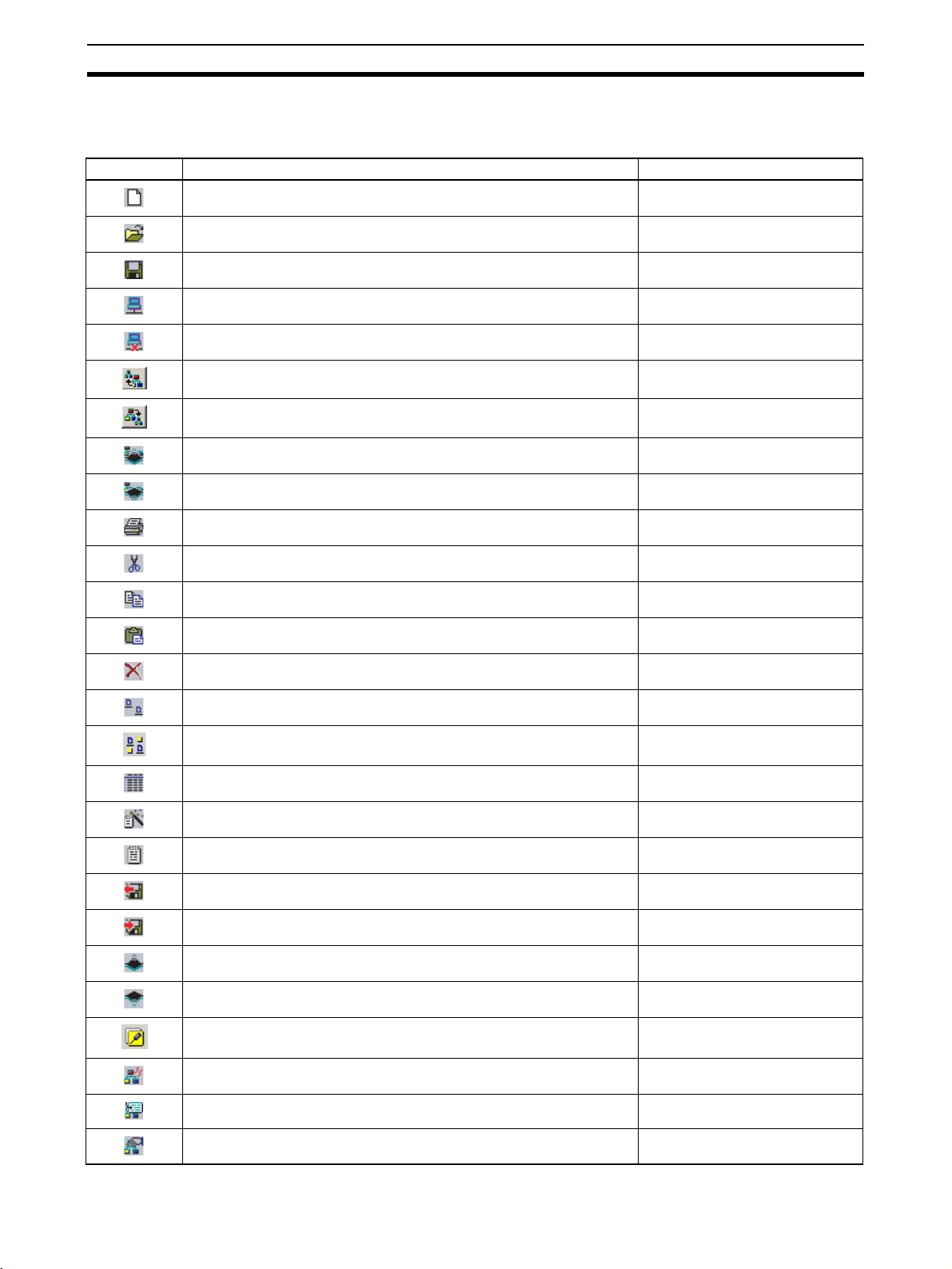
Menu Commands Section 3-2
3-2-2 Tool Bar Icons
Frequently used functions can be easily selected with the following icons.
Icon Description Equivalent menu command
Creates a new network configuration. Network−New
Opens a network configuration file. Network−Open
Saves the displayed network configuration. Network−Save
Connects the Configurator to the network. Network−Connect
Removes the Configurator from the network. Network−Disconnect
Displays the upper network. Move to Upper Network
Displays the lower network. Move to Lower Network
Uploads device data from the network to the Configurator. Network−Upload
Downloads device data from the Configurator to network devices. Network−Download
Prints. Network−Print
Cuts devices. Edit−Cut
Copies devices. Edit−Copy
Pastes devices. Edit−Paste
Deletes devices. Edit−Delete
Displays the screen in network configuration mode. ---
Maintenance mode ---
Displays the screen in detailed report mode. ---
Device parameter wizard. Device−Parameter−Wizard
Edits device parameters. Device−Parameter−Edit
Reads parameters from device parameter files. Device−Parameter−Open
Saves device parameters in files. Device−Parameter−Save As
Uploads device parameters. Device−Parameter−Upload
Downloads device parameters. Device−Parameter−Download
44
Maintenance information Device−Maintenance Information
Monitors supported network devices. Device−Monitor
Edits I/O comments. Device−Edit I/O Comment
Displays device properties. Device−Property
Page 64
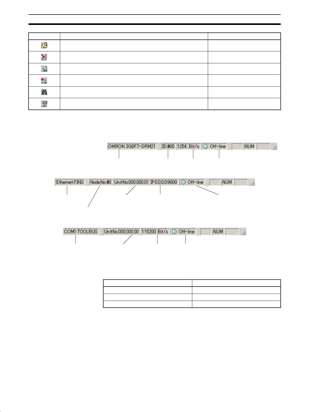
Menu Commands Section 3-2
Icon Description Equivalent menu command
Adds new EDS files. EDS File−Install
Deletes EDS files. EDS File−Delete
Saves new EDS files with new EDS file names. EDS File−Save As
Adds the selected device to the Network Configuration Window. EDS File−Add to Network
Searches for EDS files. EDS File−Find
Displays EDS file properties. EDS File−Property
3-2-3 Status Bar
The status bar displays menu explanations and the status of the Configurator.
When Connecting Via DeviceNet Dedicated Board
When Connecting Via Ethernet
Connection
interface
Node address
Connected DeviceNet Unit:
Network address
Node address
Unit number
When Connecting Via Serial Port
Connection
interface
Connected DeviceNet Unit:
Network address
Node address
Unit number
According to the status of the Configurator, the status portion will change as
shown below.
Gray Offline
Blue Online
Red Bus OFF error
Connection interface
Indicator color Status
Node address Baud rate Status
Connected Ethernet Unit:
IP address
UDP port No.
Baud rate Status
Status
Note If a Bus OFF error is detected, set the Configurator offline and set it online
again.
45
Page 65
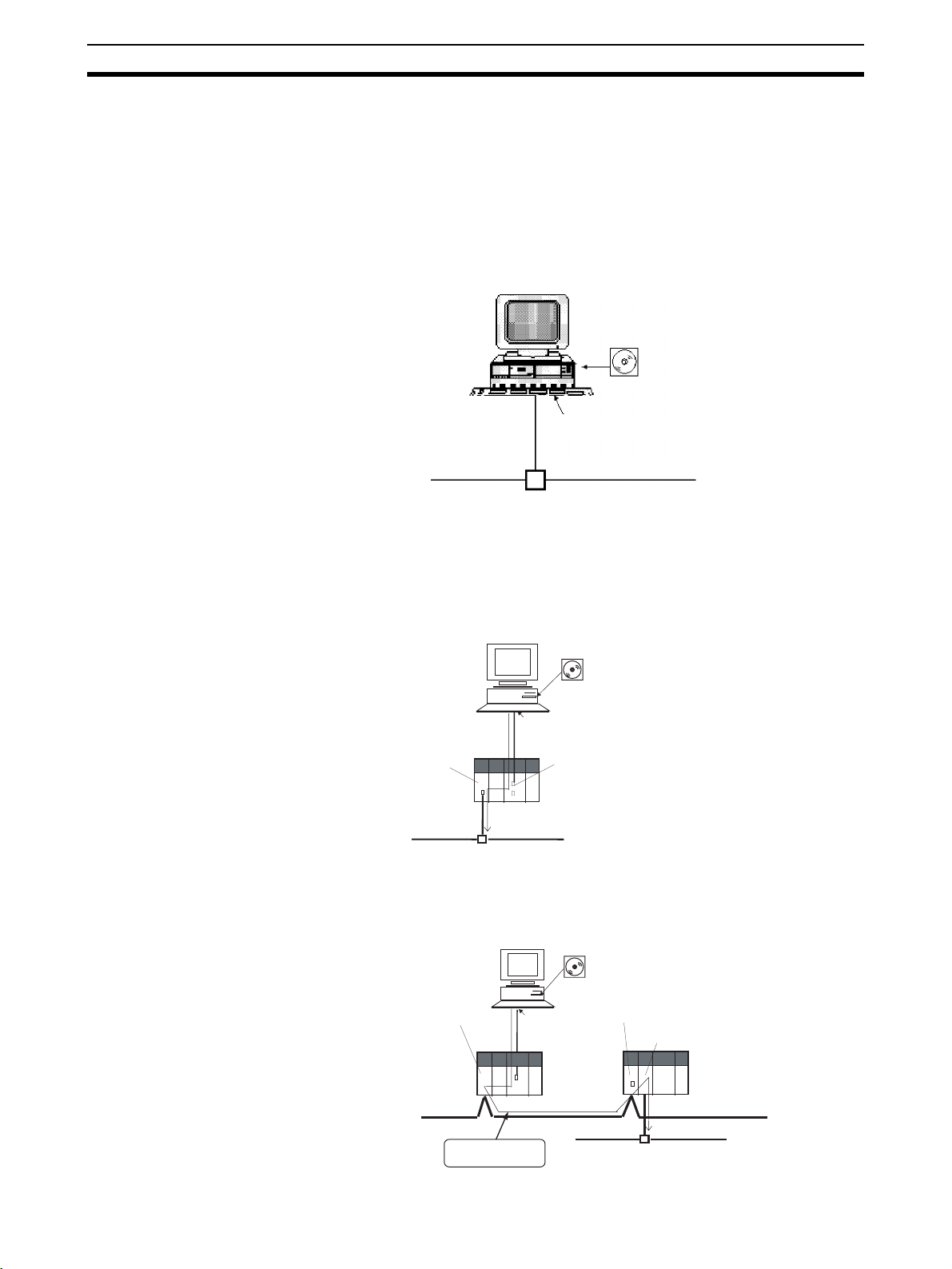
Connecting to the Network Section 3-3
3-3 Connecting to the Network
3-3-1 Connecting to the DeviceNet Network
The Configurator can be connected to the DeviceNet network online through
either of the following interfaces.
1,2,3... 1. Dedicated Board/Card
3G8F5-DRM21-E: Dedicated ISA Board
3G8E2-DRM21-EV1: Dedicated PCMCIA Card
WS02-CFDC1-E
Configurator
Dedicated Board/Card
DeviceNet network
2. Connection can also be made from the COM port of the computer to the
serial communications port (peripheral port, RS-232C port) of a CS/CJ-series CPU Unit or to the serial communications port (RS-232C port or
RS422A/485 port) of a Serial Communications Board/Unit. In this case, a
CS/CJ-series DeviceNet Unit (CS1W-DRM21 or CJ1W-DRM21) is necessary for connection to the DeviceNet network.
WS02-CFDC1-E
Configurator
COM port
CS/CJ-series
DeviceNet Unit
Serial connection Toolbus or Host
Link)
Serial communications port (peripheral
port, RS-232C port) of a CS/CJ-series CPU
Unit or to the serial communications port
(RS-232C port) of a Serial Communications
DeviceNet network
Board/Unit.
If the Configurator is Ver. 2.11 or later, it is possible to connect to the DeviceNet network across (up to three) network levels via serial communications, as shown below.
WS02-CFDC1-E
Configurator
Controller Link Unit
COM port
Serial connection
(Toolbus or Host Link)
Controller Link Unit
CS/CJ-series DeviceNet Unit
46
Controller Link network
Across network
levels
DeviceNet network
Page 66

Connecting to the Network Section 3-3
3. Connection can be made from the Ethernet port of the computer via a CS/
CJ-series Ethernet Unit. In this case also, a CS/CJ-series DeviceNet Unit
(CS1W-DRM21 or CJ1W-DRM21) is necessary for connection to the DeviceNet network.
WS02-CFDC1-E
Configurator
Ethernet port
CS/CJ-series
Ethernet Unit
CS/CJ-series
DeviceNet Unit
CPU Unit
If the Configurator is Ver. 2.11 or later, it is possible to connect to the DeviceNet network across (up to three) network levels via Ethernet, as shown
below.
CS/CJ-series
Ethernet Unit
3-3-2 Designating the Interface
Use the following procedure to designate the interface.
Note The interface is designated together with online connection settings.
Ethernet network
WS02-CFDC1-E
Configurator
Ethernet network
Controller Link Unit
CPU Unit
Controller Link network
Across network levels
DeviceNet network
Controller Link Unit
CS/CJ-series DeviceNet Unit
DeviceNet network
1,2,3... 1. Select Select Interface from the Option Menu.
(The interface presently selected is indicated with a check mark.)
2. Select the interface from those displayed on the menu.
•Select DeviceNet IF Card if a dedicated Board or Card is used.
•Select SYSMAC CS1 IF Port for a serial port connection.
•Select SYSMAC CS/CJ Ethernet Unit IF for an Ethernet connection.
Note The interface cannot be changed when the Configurator is online.
Select Network and Cancel Connection first. Then select the inter-
face offline.
3. Select Network and Connection from the menu bar.
The window corresponding to the designated interface will be displayed.
47
Page 67
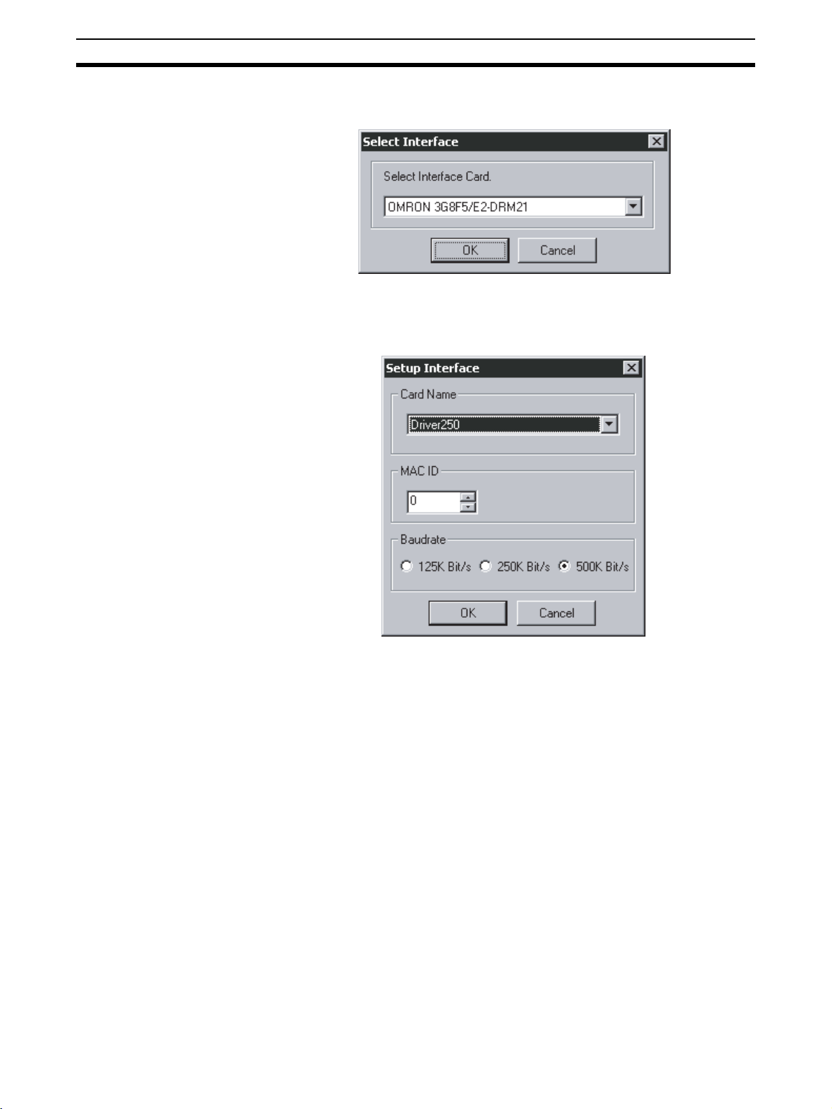
Connecting to the Network Section 3-3
Selecting DeviceNet IF Card
4. The DeviceNet Board Selection Window will open.
5. Select the DeviceNet interface to be used and click the OK Button.
The Setup Interface will appear.
For the 3G8F5-DRM21-E or 3G8E2-DRM21-EV1
Set the following items.
Card
The card name that was set with the driver setup tool is specified.
MAC ID
Specify the node address of the Configurator. Set a unique node address.
Baud Rate
Set the same baud rate as the one set for the DeviceNet network. A network
communications error may result if the same baud rate is not used.
6. Click the OK Button.
A confirmation window will appear. Click the OK Button. The Configurator
will be connected to the DeviceNet network. When the Configurator is connected online, the color of the status indicator on the status bar will change
to blue and Online will be displayed.
48
Page 68
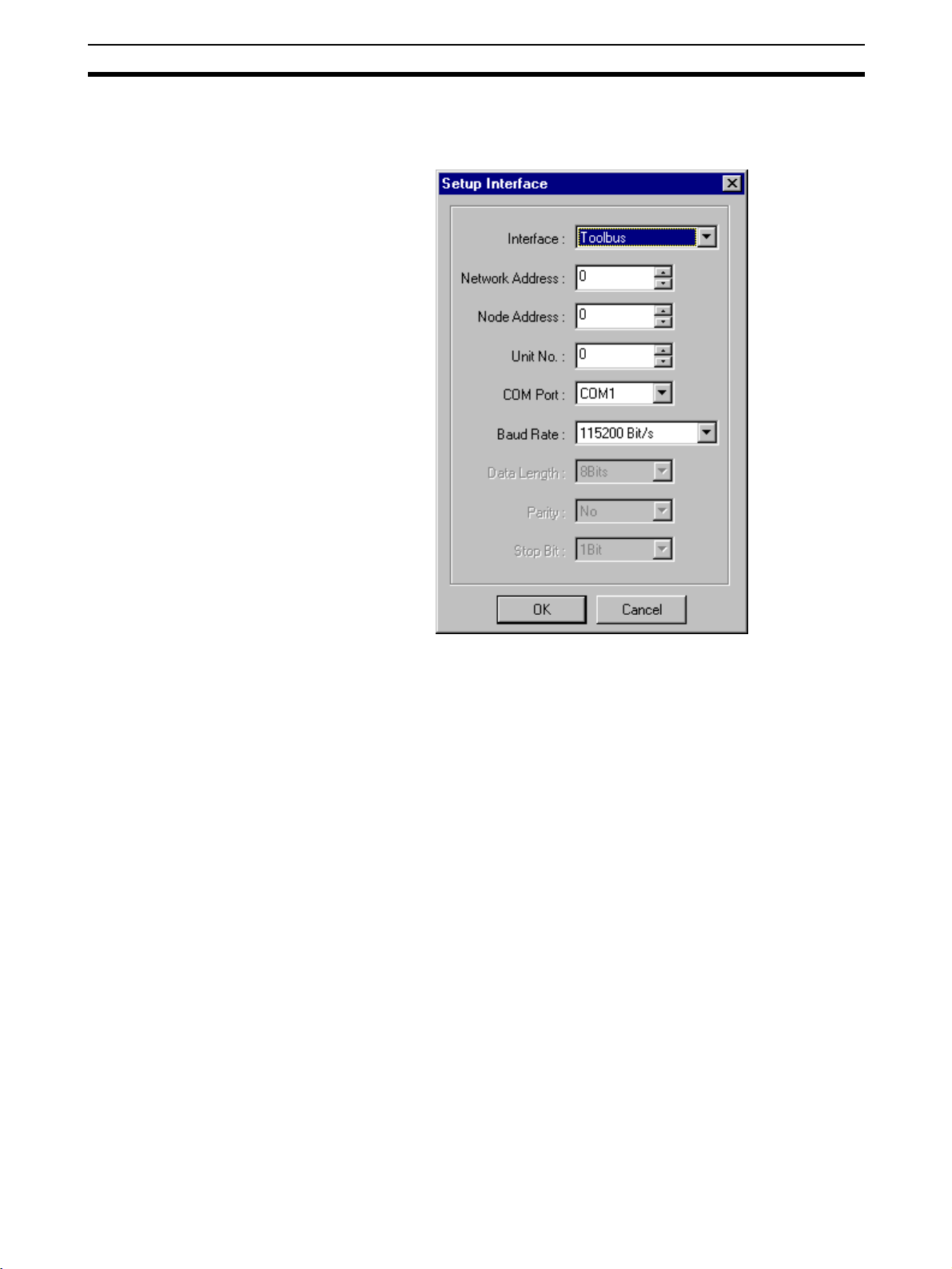
Connecting to the Network Section 3-3
Selecting SYSMAC CS/CJ
IF Port
Perform steps 1 through 3 of the above procedure.
4. The Setup Interface Dialog Box will appear if a SYSMAC CS/CJ IF Port is
specified.
Set the following items.
Interface
Select the interface from the following settings for the serial communications
mode at the serial communications port of the CS/CJ-series PLC.
• Host Link
• Toolbus
Network Address
Input the network address of the DeviceNet Unit to be connected. Input if
crossing networks past the serial communications of the CS/CJ-series CPU
Unit. If not crossing networks, input 0.
Node Address
Input the node address of the DeviceNet Unit to be connected. Input if crossing networks past the serial communications of the CS/CJ-series CPU Unit. If
not crossing networks, input 0.
Unit No.
Input the unit number within the following range for the CS1W-DRM21
DeviceNet Unit as a CPU Bus Unit. The unit number must be the same as that
set with the thumbwheel switches on the front panel of the CS1W-DRM21.
• 0 to 15
COM Port
Select the COM port of the computer running the Configurator within the following range.
• Select from the list of usable COM ports.
49
Page 69
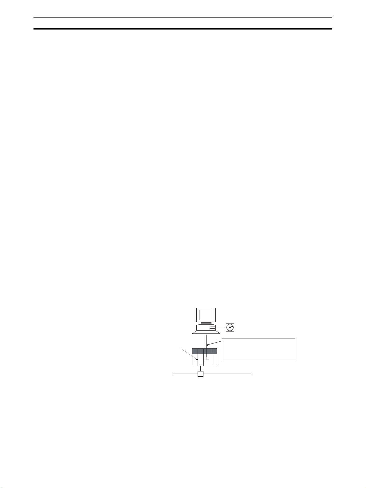
Connecting to the Network Section 3-3
Baud Rate
Select the baud rate for the serial communications port of the CS/CJ-series
PLC from the following settings.
• 9,600 bps, 19,200 bps, 38,400 bps, or 115,200 bps
Note The Tool bus and Host Link are different to each other in available
baud rate. For details, refer to the CS/CJ Operation Manual.
Data Length
Select the data length for the serial communications port of the CS/CJ-series
PLC from the following settings if Host Link is used.
• 8 or 7 bits
Parity
Select the parity for the serial communications port of the CS/CJ-series PLC
from the following settings if Host Link is used.
• None, even, or odd
Stop Bits
Set the number of stop bits for the serial communications port of the CS/CJseries PLC from the following settings if Host Link is used.
• 1 bit or 2 bits
5. Click the OK Button.
A confirmation window will appear. Click the OK Button. The Configurator
will be connected to the DeviceNet network. When the Configurator is connected online, the color of the status indicator on the status bar will change
to blue and Online will be displayed.
Note When using a CS1W-CN226/626 or XW2Z-200S-CV/500S-CV Connecting
Note When Host Link is selected, it may take several minutes to download from the
Selecting SYSMAC CS/CJ
Ethernet Unit IF
Cable to make a serial connection to a CS-series CPU Rack containing a
CS1W-DRM21, Host Link is selectable as the interface, but connection will not
be possible if it is selected. In this case, select
Toolbus.
However, when using an XW2Z-200S-CV/500S-CV Connecting Cable or
CS1W-CN114 + CQM1-CIF02, connection is possible by selecting Host Link
as the interface.
WS02-CFDC1-E
Configurator
CS-series
DeviceNet Unit
network. Selecting
Toolbus is therefore recommended for serial connections.
When using a CS1W-CN226/
626 or XW2Z-200S-CV/500SCV Connecting Cable, Host Link
cannot be used. Select Toolbus.
DeviceNet network
The Configurator can be connected directly to the DeviceNet network via
Ethernet through a CS/CJ-series Ethernet Unit and a CS/CJ-series DeviceNet
Unit.
50
Note The Ethernet connection can be made only with the CS/CJ-series Ethernet
Unit and CS/CJ-series DeviceNet Unit combination. Connection by the combination of other PLC-series Units is not possible.
Page 70

Connecting to the Network Section 3-3
Also, if multiple PLCs (using Ethernet Units and DeviceNet Units) are connected via Ethernet, connection can be made to a designated DeviceNet network by switching the connection target. The IP address of the Ethernet Unit
and the unit number of the DeviceNet Unit are designated to register the
DeviceNet network to be connected.
DeviceNet Configurator
Ver. 2.11
FINS node address
Switchable (See
note 1.)
Ethernet
IP
address
Ethernet
Unit
DeviceNet
CS-series
CPU Unit
Unit
DeviceNet
Unit
number
CJ-series
CPU Unit
IP address
Across the
network
Controller
Ethernet
Unit
Link Unit
Controller Link
Controller
Link Unit
CJ-series
CPU Unit
DeviceNet
Unit
DeviceNet
Unit number
node address
Network Address
Note 1. DeviceNet networks can be switched by designating the registered name
for the network to be connected. The name of the DeviceNet network to be
connected can be registered as follows.
• Designate the IP address and UDP port number.
• Designate the DeviceNet Unit network address, node address, and Link
Unit number.
• Designate the FINS node address of the personal computer containing
the Configurator.
2. Connection is not possible through the combination of a CVM1/CV Ethernet Unit and CVM1/CV DeviceNet Unit. It is also not possible through the
combination of a C200HX/HG/HE PLC Card Unit (Ethernet Set) and
C200HX/HG/HE DeviceNet Master Unit.
3. Configurator Ver. 2.10 allows Ethernet connection to the DeviceNet network across one network level only. DeviceNet networks cannot be connected to across multiple network levels. (For example, configurations
such as Ethernet
→ Controller Link → DeviceNet, or Host Link (Toolbus)
Ethernet → DeviceNet are not possible.)
With Configurator Ver. 2.11 or later, it is possible to cross network levels as
long as FINS message communications are supported by the networks.
Registering DeviceNet
Networks to Be
Connected
1,2,3... 1. Select Network and Connect.
For connection via Ethernet, the DeviceNet network(s) to be connected must
be registered in advance. Up to 20 DeviceNet networks can be registered,
using the following procedure.
51
Page 71
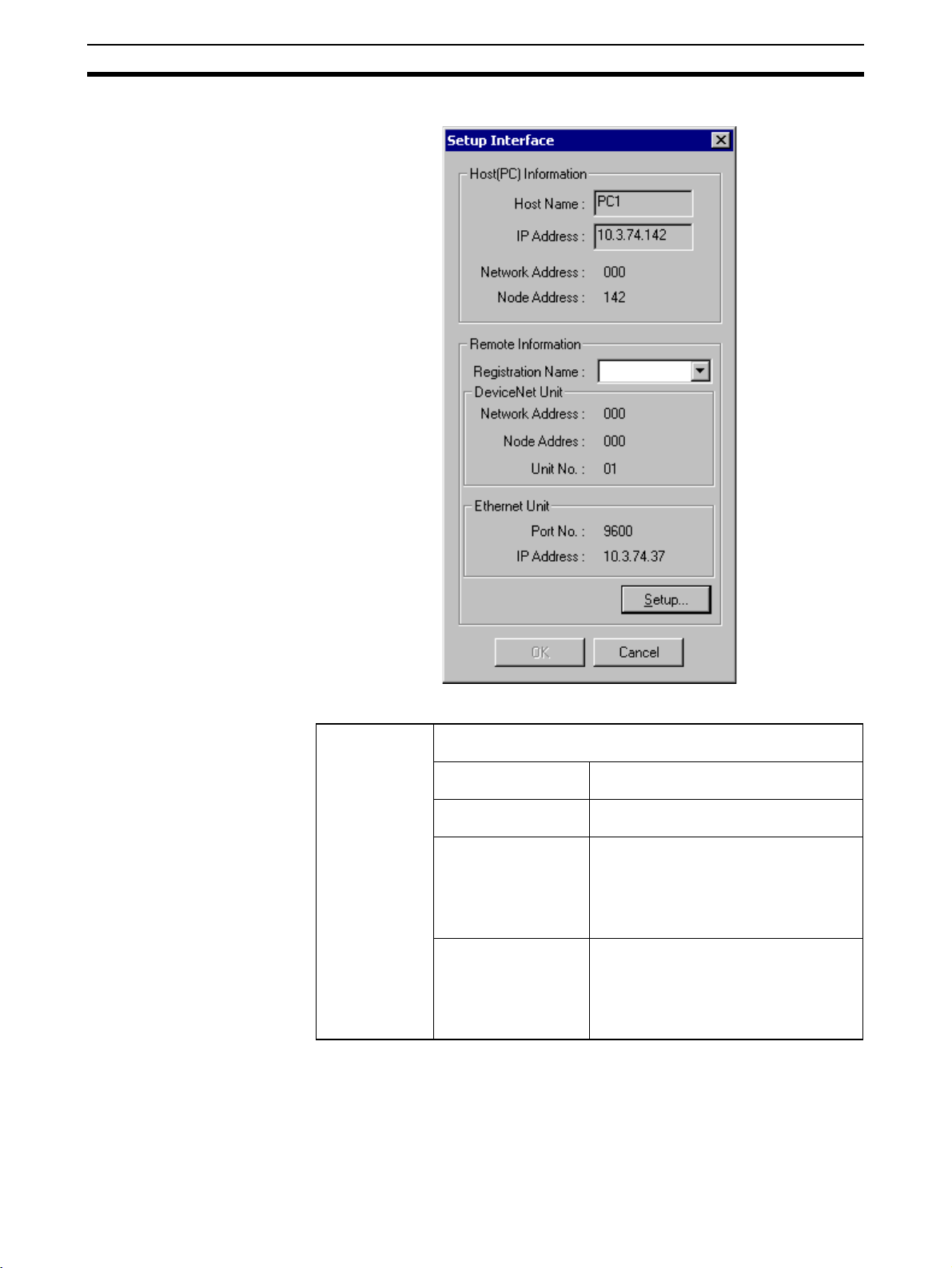
Connecting to the Network Section 3-3
2. The Setup Interface Dialog Box shown below will appear.
Setup Interface Dialog Box
Host (PLC) Information
The settings for the computer running the Configurator will be displayed.
Host Name The name of the computer will automati-
IP Address The IP address of the computer will auto-
Network Address The FINS network address set for the
Node Address The FINS node address set for the com-
cally appear.
matically appear.
computer will appear. (The value set with
the Registration of the connection Dialog
Box, after clicking the Setup Button as
described in following step (step 3), will
appear.)
puter will appear. (The value set with the
Registration of the connection Dialog
Box, after clicking the Setup Button as
described in the following step (step 3),
will appear.)
52
Page 72

Connecting to the Network Section 3-3
3. Click the Setup Button. The Registration of the connection Dialog Box shown below will be displayed.
53
Page 73

Connecting to the Network Section 3-3
Registration of the connection Dialog Box
Registration
Name
Host (PLC)
Information
Remote Information
The registration name for the DeviceNet network to be connected is
set here. Up to 20 networks can be set, each up to 25 characters in
length.
This is the setting for the Configurator computer.
Network
Address
Node address The user inputs the FINS node address for the com-
These are the settings for the DeviceNet Unit and Ethernet Unit that
are used to connect with the DeviceNet network.
DeviceNet
Unit
The user inputs the FINS network address for the
computer here. Set the same address as the one set
for the Ethernet Unit. Input 0 if no other address is
going to be set.
puter here.
Network
Address
Input the FINS network address for
the DeviceNet to be connected.
Input if crossing networks past
the direct Ethernet connection. If
not crossing networks, input 0.
Node Address Input the node address for the
DeviceNet to be connected.
Input if
crossing networks past the
direct Ethernet connection. If not
crossing networks, input 0.
Unit No. Input the unit No. of the DeviceNet
Ethernet Unit Port No. Input the Fins UDP port No. for the
IP Address Input the IP address for the Ethernet
to be connected, for use as a CPU
Bus Unit.
Ethernet Unit.
Unit.
Setting the Network Address in Host (PLC) Information:
Set the FINS network address for the computer. The computer running the
Configurator uses OMRON’s FINS communications service to connect to the
DeviceNet network via Ethernet. Thus, the computer must have not only an IP
address, but also a FINS network address and node address. The relationship between the FINS node address and the IP address is specified by the
address conversion in the Ethernet Unit.
Obtain the FINS node address corresponding to the IP address (See note.) of
the computer from the address conversion of the Ethernet Unit. Refer to
mation on Address Conversion
on page 56 for details.
Infor-
Setting the Node Address in Host (PLC) Information:
Set the FINS node address for the computer.
Obtain the FINS node address corresponding to the IP address (See note.) of
the computer from the address conversion of the Ethernet Unit. Refer to
mation on Address Conversion
on page 56 for details.
Infor-
54
Page 74
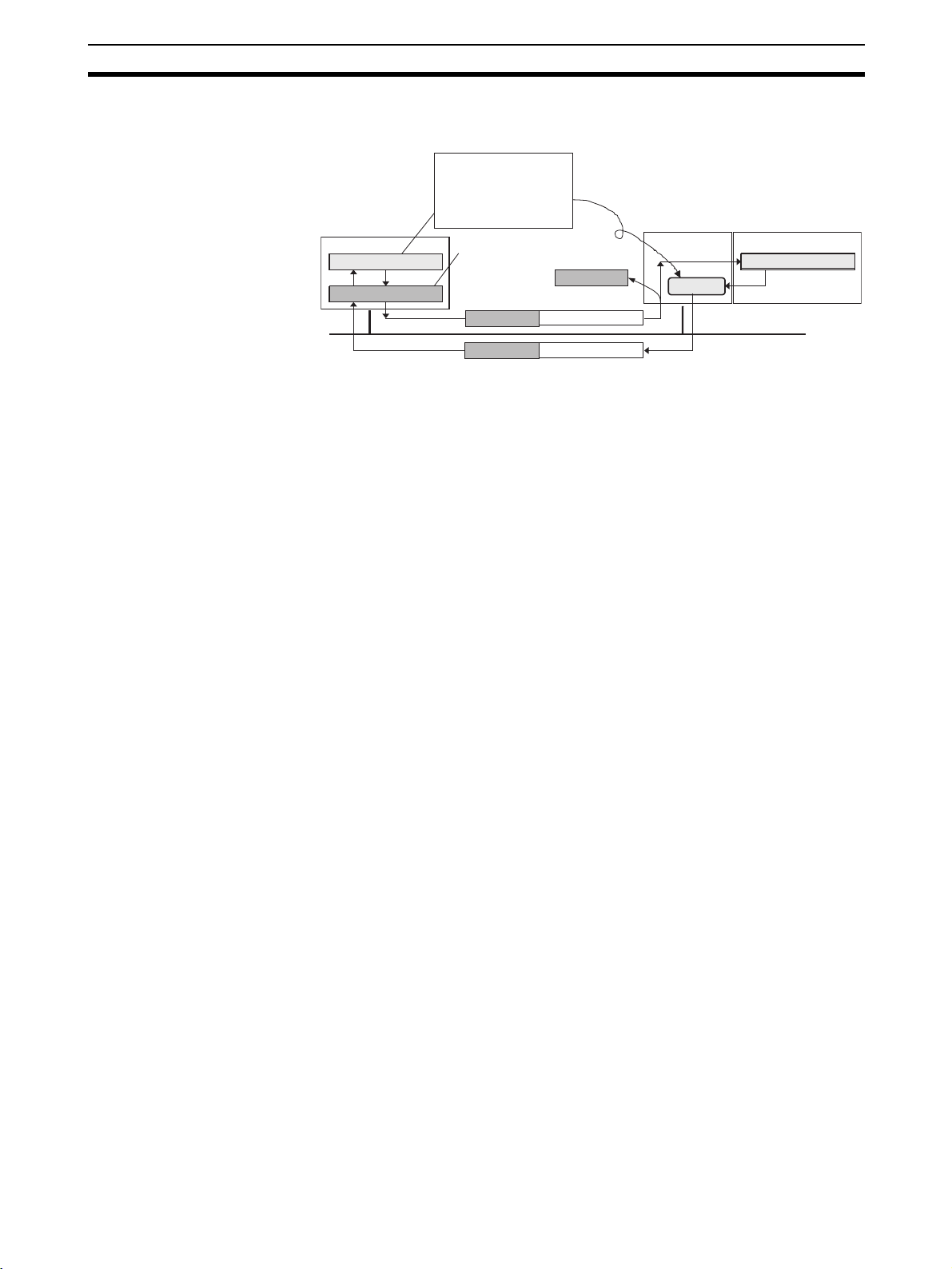
Connecting to the Network Section 3-3
Note The computer’s IP address is automatically displayed in the Host (PLC) Infor-
mation setting in the Setup Interface Dialog Box.
Obtain this value in
reverse from the
computer’s IP address,
by using the address
Personal
computer
FINS node address
IP address
Setting the Network Address in the DeviceNet Unit Section Inside Remote
Information
Set the FINS network address of the DeviceNet Unit on the DeviceNet network to be connected. Input if crossing networks past the direct Ethernet connection. If not crossing networks, input 0.
Setting the Node Address in the DeviceNet Unit Section Inside Remote
Information
Set the node address of the DeviceNet Unit on the DeviceNet network to be
connected. Input if crossing networks past the direct Ethernet connection. If
not crossing networks, input 0.
conversion of the
Ethernet Unit.
This value (computer’s IP
address) is shown in the
host information.
IP address FINS message
IP address
IP address
FINS message
Address
conversion
CPU UnitEthernet Unit
FINS node address
Ethernet
Setting the Port No. in the Ethernet Unit Section Inside Remote
Information
Set the UDP port No. for FINS communication service by the Ethernet Unit.
Set it to the same value that is set in the CPU Bus Unit System Setting Area
inside the CPU Unit to which the Ethernet Unit is mounted. Normally, this setting is 9600.
Setting the Unit. No in the DeviceNet Unit Section Inside Remote
Information
Set the unit No. (0 to F) of the DeviceNet Unit for CPU Bus Unit use on the
DeviceNet network to be connected.
Setting the IP Address in the Ethernet Unit Section Inside Remote
Information
Set the IP address for the Ethernet Unit. For the CS-series Ethernet Unit, the
value that is set with the rotary switch on the back of the Unit is input here. For
the CJ-series Ethernet Unit, the value that is set in the Allocated Words in the
DM Area, or in the System Setup for CPU Bus Units, is input here.
Note For details on setting the IP address for the Ethernet Unit, refer to the SYS-
MAC CS/CJ-series Ethernet Units Operation Manual (catalog No. W343).
4. Click the Add Button. The set value is registered and displayed in the Register List.
• Registration Name: The registration name for the DeviceNet network to
be connected to.
• Node: The FINS network address and FINS node address. (The third
digit is always 0.)
• Unit: The FINS network address, FINS node address, and unit number of
the DeviceNet Unit.
55
Page 75

Connecting to the Network Section 3-3
• Port: The FINS UDP port No. for the Ethernet Unit.
• IP Address: The IP address for the Ethernet Unit.
5. To exit the registration procedure, click the Close Button. The Setup Interface Dialog Box will be displayed again.
Selecting the Registration
Name
Information on Address
Conversion
Select the DeviceNet network to be connected to from among those in the
Registration Name column that were set with the Setup Interface Dialog Box.
1. Select the desired Registration Name from the Registration Name dropdown list in Remote Information. The following parameters are displayed
for the selected Registration Name in Remote Information.
• Network Address: The FINS network address for the DeviceNet Unit.
• Node Address: The node address for the DeviceNet Unit.
• Unit No.: The unit No. DeviceNet Unit.
• Port No.: The FINS UDP port No. for the Ethernet Unit.
• IP Address: The IP address for the Ethernet Unit.
2. Click the OK Button.
A confirmation window will appear. Click the OK Button. The Configurator
will be connected to the DeviceNet network. When the Configurator is connected online, the color of the status indicator on the status bar will change
to blue and Online will be displayed.
Ethernet Unit Address Conversion Method
The FINS communications service is used inside the PLC. Because there is
no IP address information added to the FINS communications service, the IP
address is determined from the FINS node address in order to send a FINS
message (command or response) with the PLC’s Ethernet Unit.
The Ethernet Unit address conversion is done by either of the three following
methods (set in the System Setup for CPU Bus Units of the CPU Unit to which
the Ethernet Unit is mounted).
• IP address table
• Automatic generation
• Combined method
The computer’s FINS node address calculation for each address conversion
method is described below.
Address conversion
method
Computer’s FINS node address calculation
IP address table The FINS node address is set according to the
computer’s IP address based on a preset correspondence table called an IP address table.
Automatic generation The FINS node address is automatically generated
from the computer’s IP address and the subnet
mask.
Combined method
If the computer’s IP address has been set in the IP
address table, the FINS node address in the table is set.
If the computer’s IP address has not been set in the IP
address table, a FINS node address that is automatically
generated from the computer’s IP address, or from the
subnet mask, is set.
56
Note For details on address conversion, refer to the SYSMAC CS/CJ-series Ether-
net Units Operation Manual (catalog No. W343).
Page 76

Connecting to the Network Section 3-3
Obtaining the FINS Node Address from the Automatic Generation Method
of Address Conversion
The FINS node address corresponding to the computer’s IP address is
obtained from the rightmost byte of the computer’s IP address and the rightmost byte of the network address as follows:
FINS node address = The rightmost byte of (the Ethernet Unit’s IP address
AND the Ethernet Unit’s subnet mask) XOR the rightmost byte of the computer’s IP address.
This can be easily calculated using the Windows Calculator.
Note Address conversion from the Ethernet Unit’s automatic generation method is
obtained as follows.
Computer’s IP address = (the Ethernet Unit’s IP address AND the Ethernet
Unit’s subnet mask) OR FINS node address.
Accordingly, the FINS node address can be determined by taking the XOR of
the network address and the computer’s IP address.
(1)
130. 25. 36. 8
AND 255. 255. 255. 0
130. 25. 36.
OR 5
130. 25. 36.
XOR of (1) and (2)
Ethernet Unit’s IP address
Ethernet Unit’s subnet mask
0
(obtain the “network address”)
FINS node address
5
Computer’s IP address
(2)
Calculation example:
Computer’s IP address = 192.168.10.100
Ethernet Unit’s IP address = 192.168.10.119
Ethernet Unit’s subnet mask = 255.255.255.224
FINS node address = (119 AND 224) XOR 100 = 4
(1)
192. 168. 10. 119
AND 255. 255. 255. 224
130. 25. 36.
OR 5
192. 168. 10.
XOR of (1) and (2)
Ethernet Unit’s IP address
Ethernet Unit’s subnet mask
0
(obtain the “network address”)
FINS node address
100
Computer’s IP address
(2)
57
Page 77

Operation Flowcharts Section 3-4
3-4 Operation Flowcharts
The following flowcharts show the flow of Configurator operations.
3-4-1 Offline Operation
Prior to constructing the actual network, it can be designed and the master
and slave parameters can be set with the Configurator.
The set parameters can be saved as a network configuration file. The network
configuration file contains the parameters of all of the devices on the network.
Start the Configurator.
3-1 Starting the Configurator and the Main Window
on page 38.
Add DeviceNet to the virtual network.
Set the slave parameters (only for the
slaves that require parameter setting).
Register the slaves with the master.
Set the master’s parameters.
Save the settings as a network configuration file.
4-1 Adding Devices to the Virtual Network
on page 60.
4-2 Setting Slave Parameters on page 64.
4-3 Adding Slaves to the Master on page 68.
4-5 Editing Master Parameters on page 73.
6-1 Saving and Reading Files on page 128.
3-4-2 Downloading Saved Parameters
The parameters for all of the devices on the network can be set (downloaded)
from a network configuration file saved in advance.
Start the Configurator.
Read the network configuration file.
Connect to the network (online).
3-1 Starting the Configurator and the Main Window
on page 38.
6-1-2 Reading Network Configuration Files
on page 128.
3-3 Connecting to the Network on page 46.
Download to the network or download
parameters to each device.
5-2 Downloading the Network Configuration/
Device Parameters to Devices
on page 108.
3-4-3 Saving the Parameters for the Entire Existing Network
The parameters for all of the devices on the network can be saved for use in
maintenance.
Start the Configurator.
Connect to the network (online).
Upload from the network.
Save the settings as a network configuration file.
58
3-1 Starting the Configurator and the Main Window
on page 38.
3-3 Connecting to the Network on page 46.
5-3 Uploading and Verifying Device Parameters
on page 113.
6-1 Saving and Reading Files on page 128.
Page 78

SECTION 4
Editing Device Parameters
This section explains how to enable remote I/O communications by creating device parameters for a virtual network
constructed with the DeviceNet Configurator.
4-1 Adding Devices to the Virtual Network . . . . . . . . . . . . . . . . . . . . . . . . . . . . . 60
4-1-1 Adding Devices. . . . . . . . . . . . . . . . . . . . . . . . . . . . . . . . . . . . . . . . . 60
4-1-2 Changing Node Addresses . . . . . . . . . . . . . . . . . . . . . . . . . . . . . . . . 61
4-1-3 Reading the Network Configuration from the Network . . . . . . . . . . 61
4-1-4 Editing Devices. . . . . . . . . . . . . . . . . . . . . . . . . . . . . . . . . . . . . . . . . 62
4-2 Setting Slave Parameters. . . . . . . . . . . . . . . . . . . . . . . . . . . . . . . . . . . . . . . . . 64
4-2-1 Editing Slave Parameters . . . . . . . . . . . . . . . . . . . . . . . . . . . . . . . . . 64
4-2-2 Checking and Setting I/O Size . . . . . . . . . . . . . . . . . . . . . . . . . . . . . 67
4-3 Adding Slaves to the Master . . . . . . . . . . . . . . . . . . . . . . . . . . . . . . . . . . . . . . 68
4-3-1 Automatic I/O Area Allocation with Registration . . . . . . . . . . . . . . 68
4-3-2 Adding Slaves. . . . . . . . . . . . . . . . . . . . . . . . . . . . . . . . . . . . . . . . . . 70
4-4 Setting Master Properties . . . . . . . . . . . . . . . . . . . . . . . . . . . . . . . . . . . . . . . . 71
4-4-1 CS1W-DRM21 and CJ1W-DRM21 . . . . . . . . . . . . . . . . . . . . . . . . . 71
4-4-2 CVM1-DRM21-V1 or C200HW-DRM21-V1 . . . . . . . . . . . . . . . . . 72
4-5 Editing Master Parameters . . . . . . . . . . . . . . . . . . . . . . . . . . . . . . . . . . . . . . . 73
4-6 Parameter Wizard . . . . . . . . . . . . . . . . . . . . . . . . . . . . . . . . . . . . . . . . . . . . . . 74
4-7 Master Parameter Editing Details (Tab Descriptions). . . . . . . . . . . . . . . . . . . 78
4-7-1 Edit Device Parameters on CS1W-DRM21/CJ1W-DRM21. . . . . . . 79
4-7-2 Editing Device Parameters on CVM1-DRM21-V1 and
C200HW-DRM21-V1. . . . . . . . . . . . . . . . . . . . . . . . . . . . . . . . . . . . 82
4-7-3 Canceling Slave Registration with the Master . . . . . . . . . . . . . . . . . 84
4-7-4 Automatic Allocation with Registration. . . . . . . . . . . . . . . . . . . . . . 84
4-8 Manual I/O Allocations. . . . . . . . . . . . . . . . . . . . . . . . . . . . . . . . . . . . . . . . . . 84
4-8-1 I/O Allocation Tab Page . . . . . . . . . . . . . . . . . . . . . . . . . . . . . . . . . . 84
4-8-2 Changing the First Address of Output/Input Block . . . . . . . . . . . . . 86
4-8-3 Allocating I/O . . . . . . . . . . . . . . . . . . . . . . . . . . . . . . . . . . . . . . . . . . 87
4-8-4 Slave Information . . . . . . . . . . . . . . . . . . . . . . . . . . . . . . . . . . . . . . . 90
4-9 Advanced Settings (Connection, Communication Cycle Time,
Slave Function Settings, Etc.) . . . . . . . . . . . . . . . . . . . . . . . . . . . . . . . . . . . . . 91
4-9-1 Advanced Settings . . . . . . . . . . . . . . . . . . . . . . . . . . . . . . . . . . . . . . 91
4-9-2 Communication Cycle Time Settings. . . . . . . . . . . . . . . . . . . . . . . . 93
4-9-3 Setting Message Timers . . . . . . . . . . . . . . . . . . . . . . . . . . . . . . . . . . 94
4-9-4 Slave Function Settings . . . . . . . . . . . . . . . . . . . . . . . . . . . . . . . . . . 95
4-9-5 Setting/Canceling Explicit Message Communications. . . . . . . . . . . 96
4-9-6 Starting Remote I/O Communications . . . . . . . . . . . . . . . . . . . . . . . 96
4-10 Creating and Editing I/O Comments. . . . . . . . . . . . . . . . . . . . . . . . . . . . . . . . 96
4-11 Displaying Device Properties . . . . . . . . . . . . . . . . . . . . . . . . . . . . . . . . . . . . . 98
4-11-1 Property Window Common to All Devices . . . . . . . . . . . . . . . . . . . 98
4-11-2 I/O Information Inherent to Each Slave Device . . . . . . . . . . . . . . . . 99
4-11-3 Information for Master . . . . . . . . . . . . . . . . . . . . . . . . . . . . . . . . . . . 101
59
Page 79

Adding Devices to the Virtual Network Section 4-1
4-1 Adding Devices to the Virtual Network
This section describes how to add devices (master and slave devices) to the
virtual network in the Network Configuration Window of the Configurator.
4-1-1 Adding Devices
To add a device, drag the device from the Hardware List Window and drop it
on the Network Configuration Window.
Select the device from the Hardware List Window on the left and then drag
and drop it on the Network Configuration Window on the right.
Adding a Master
The Unit icon will be displayed
when the master is registered.
Drag and Drop to register.
Adding Slaves Drag and drop the slaves in sequence in the same way.
The Unit icon will be
displayed when the
slave is registered.
60
Page 80
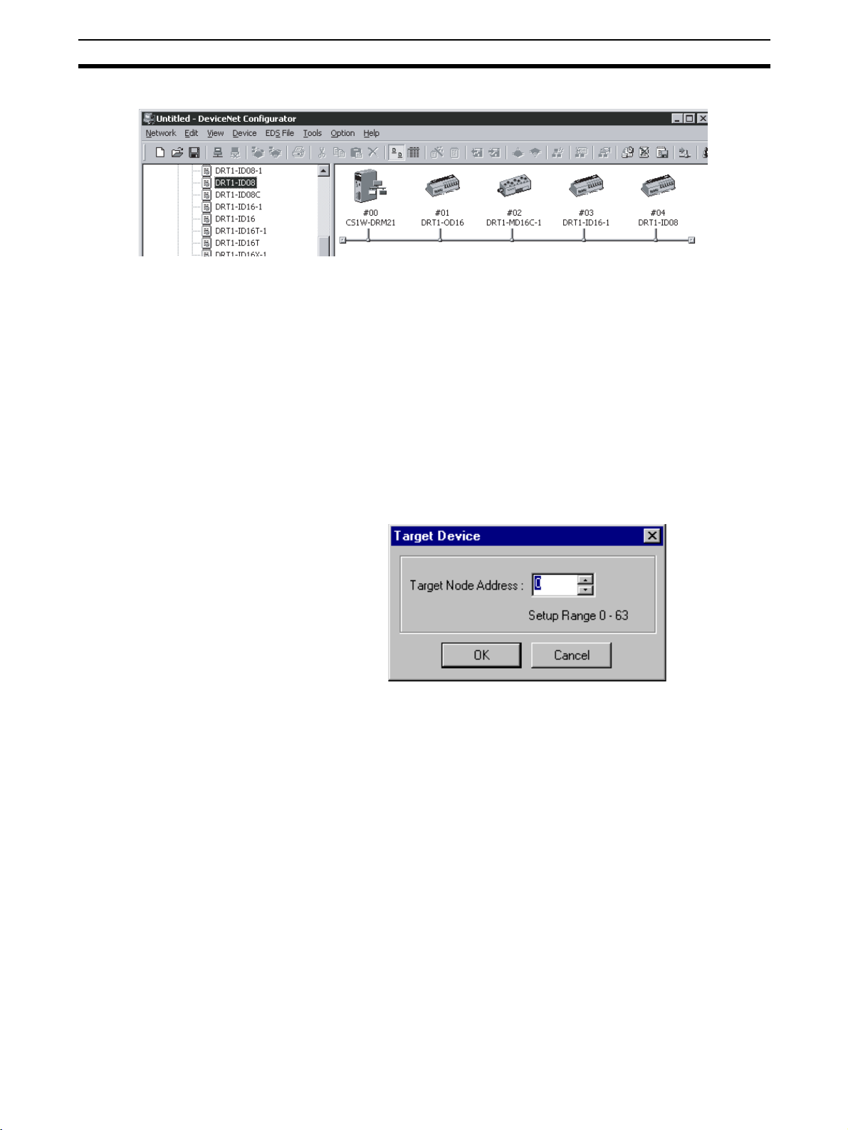
Adding Devices to the Virtual Network Section 4-1
Example of Addition by Dragging
Note A device can be also added by selecting the device in the hardware list on the
left pane, clicking the right mouse button, and selecting Add to Network or by
selecting Add to Network from the EDS File Menu.
4-1-2 Changing Node Addresses
Device - Change
Device ID
1,2,3... 1. Select the device for which the node address is to be changed.
Unused node addresses between 0 and 63 will be allocated in sequence to
the respective devices that have been added.
To change the allocated node addresses, use the following procedure.
2. Select Device and Change Device ID or click the right mouse button and
select Chance Device ID from the pop-up menu.
The following window will be displayed.
3. Click the OK Button to change the node address.
Repeat the above steps and add all the necessary devices to the Network
Configuration Window.
4-1-3 Reading the Network Configuration from the Network
Network - Upload Use the following procedure to read the network configuration from the actual
network.
1,2,3... 1. Place the Configurator online.
2. Select Network.
3. Select Upload.
61
Page 81

Adding Devices to the Virtual Network Section 4-1
The upload operation will start and the following window indicating the uploading progress will be displayed.
The user can interrupt the upload operation by clicking the Cancel Button.
4. The network devices will be displayed in sequence in the Network Configuration Window.
5. After the upload operation completes, add any additional devices are required using the procedure explained in Adding Devices.
4-1-4 Editing Devices
Deleting Devices
Edit - Delete To delete network devices, use the following procedure.
1,2,3... 1. Select the devices. (A number of devices can be selected at one time.)
2. Select Edit.
3. Select Delete.
4. A confirmation window will be displayed. Click the OK Button to delete the
devices.
If slaves registered with the master are deleted, the slave registration with the
master will be lost and the slaves will be purged from the scan list automatically.
Copying Devices
Edit - Copy To copy the network devices, use the following procedure.
1,2,3... 1. Select the devices. (A number of devices can be selected at a time.)
2. Select Edit.
3. Select Copy.
The devices including the set parameters will be copied to the clipboard in the
Configurator.
62
Page 82

Adding Devices to the Virtual Network Section 4-1
Pasting Devices
Edit - Paste To paste a device from the clipboard in the Configurator, use the following pro-
cedure.
1,2,3... 1. Select the network device existing at the insertion position.
2. Select Edit.
3. Select Paste.
An unused node address will be allocated to the network device that was
added.
Changing Device Comments
Device - Change Device
Comment
1,2,3... 1. Select the network device.
A device comment can be added to each network device that has been registered. The product name is by default allocated as the device comment of
each network device. To change the device comment, use the following procedure.
2. Select Device.
3. Select Change Device Comment.
The following window will be displayed.
4. Input the device comment and click the OK Button.
The device comment will be displayed by moving the mouse pointer to the
position of the device in the Network Configuration Window.
Note In the Network Display Mode, the device comment will be displayed when the
mouse pointer is moved to the icon. In the Detailed Display Mode, the device
comment will be displayed in the Comment column.
Changing Device Positions
To change the display position of a network device, use the following procedure.
1,2,3... 1. Drag the network device with the right mouse button.
2. Drop the network device at the desired position occupied by another net-
3. The dragged network device will move to the specified position.
work device.
63
Page 83

Setting Slave Parameters Section 4-2
• The following example shows a network device with node address #00
is dragged and dropped on node address #02.
Right mouse button
Drop
Drag
Moving direction of existing devices
• The following example shows a network device with node address #01
is dragged and dropped on node address #02.
Right mouse button
Drop
Drag
Moving direction of existing devices
4-2 Setting Slave Parameters
4-2-1 Editing Slave Parameters
Device - Parameter - Edit The parameters of some slaves can be set. However, doing so may cause the
I/O size to change. Because of this, the slave parameters must all be set
before setting the master’s parameters.
EDS files are required for setting the parameters. If there are no EDS files
available, they must be obtained from the device manufacturer.
64
Page 84

Setting Slave Parameters Section 4-2
Note Slaves must be added to the Network Configuration Window to edit the
parameters. Creating the network configuration will be explained later in this
section.
To edit the parameters, use the following procedure.
1,2,3... 1. Select the device.
2. Select Device, Parameter, and Edit.
3. The following warning will be displayed if there are no editable parameters
existing.
Slaves for which this message is displayed do not require parameter setting.
The following window will be displayed if editable parameters exist.
Parameter group selection
Parameter names
Parameter set values
Parameter help
Device reset
Usable only when
online.
Compare parameters
Download parameters
Upload parameter
Reset parameters to default settings
Usable only when online.
Usable only when online.
Usable only when online.
Usable only when online.
4. Select the parameter and press the Enter Key or double-click the parameter.
65
Page 85

Setting Slave Parameters Section 4-2
If a push-pin icon is displayed next to a parameter name, it is a read-only
parameter and cannot be edited.
The set value will be changed as shown below according to the parameter
input type.
Numerical Input within Certain Range
Set the value between the maximum and minimum values.
Selection from Limited Items
ON/OFF Settings
Select the set value from the set value list.
66
Select the item and turn it ON or OFF.
5. Press the Enter Key to input the set value.
Press the ESC Key to cancel the change.
6. Click the OK Button when all the items have been edited.
Page 86
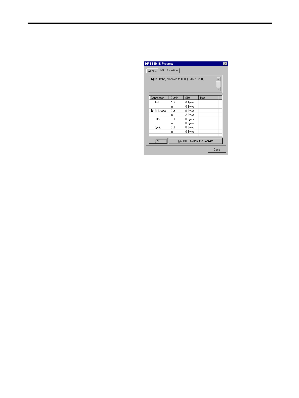
Setting Slave Parameters Section 4-2
4-2-2 Checking and Setting I/O Size
Checking I/O Size
Device - Property - I/O Information
The I/O size of this slave can be checked with the I/O Information Ta b o f t h e
Property Window. Check to make sure that the I/O size listed is correct. To
change it, use the following procedure.
Setting the I/O Size
1,2,3... 1. Select the desired slave, then select Device and Property.
For slaves in which the I/O size can be changed by switches, or by tools other
than the Configurator, the Configurator cannot be used to confirm that the I/O
size is correct.
For these slaves, use the following procedure to directly input the I/O size.
2. Select the I/O Information Ta b .
3. Click the Edit Button. The Edit I/O Size Dialog Box will be displayed.
4. Input the correct I/O size for each connection. If the connection is not
known, input the correct I/O size in the Poll settings.
5. Click the OK Button.
Note The following are OMRON slaves.
• DRT1-AD04 Analog Input Terminal
Input (4-word/2-word) can be changed by DIP switch.
• GT1-AD08MX Analog Input Unit for MULTIPLE I/O TERMINAL.
Input (8-word/4-word) can be changed by DIP switch.
• NT-DRT21 Programmable Terminal DeviceNet Interface Unit
The I/O data area can be set from 1 to 64 words with the PT system
menu.
• E3X-DRT21 Fiber Amplifier Communications Unit
Status and light levels can be added to input data.
Use the same kind of input procedure for slaves of other manufacturers that
allow the I/O size to be changed.
67
Page 87

Adding Slaves to the Master Section 4-3
Obtaining I/O Size Information from the Master Scan List
When connecting the Configurator to a network that is already operating, for
example using OMRON Master Units with fixed allocation, the slave I/O size
can be obtained from the master scan list for use in setting.
However, this is possible only with OMRON masters. Also, the slave I/O size
cannot be obtained from the slave function of the CS1W-DRM21 and CJ1WDRM21.
Use the following procedure to obtain the I/O size from a master scan list.
1,2,3... 1. Select the desired slave, then select Device and Property.
2. Select the I/O Information Ta b .
3. Click the Get I/O Size from the Scanlist Button.
Parameter Auto Update When I/O Size Changed
The function to automatically update the I/O size registered on the master
scan list when the I/O size is changed can be switched on or off.
To automatically update the I/O size registered on the master scan list, select
Option and Parameter Auto Update When I/O Size Changed.
When this function is enabled, the mark will be displayed in the menu. The
default is set to not automatically update.
Note If the function to automatically update the I/O size is enabled and there is no
EDS file, some operations will cause the I/O size in the master scan list to be
updated to zero. For this reason, the function to automatically update the I/O
size should normally be disabled.
4-3 Adding Slaves to the Master
4-3-1 Automatic I/O Area Allocation with Registration
When a slave is registered to the master, it can automatically be allocated to
the memory block set for I/O allocation.
The allocation, for both Out Size and In Size, will be made in the order of registration beginning with the unoccupied area of memory block 1. When memory block 1 is filled, the allocation will be made to memory block 2. Before
adding slaves, set the area and range of the allocation memory block.
Note The allocation area can be changed later if desired.
68
Page 88

Adding Slaves to the Master Section 4-3
Setting the Allocation
Memory Block
1,2,3... 1. Select the master, then select Device, Parameter, and Edit. The Edit De-
vice Parameters Dialog Box is then displayed.
2. Select the I/O Allocation (OUT) Ta b .
3. Click the Setup Button for Memory Block 1.
4. Set the area, start word, and the number of words for the block.
5. Set Memory Block 2 in the same way.
6. Select the I/O Allocation (IN) Tab, and make the memory block settings in
the same way as for the I/O Allocation (OUT).
Note 1. If a block is not to be used, select Not Used for the area setting.
2. Display Words refers to the number of words in the block displayed on the
Configurator. This value is not downloaded to the master.
If the occupied area of the block is less than 100 words when uploaded,
Display Words will be set to 100 and displayed as such.
69
Page 89

Adding Slaves to the Master Section 4-3
4-3-2 Adding Slaves
The following three methods are supported for adding slaves.
Dragging and Dropping Select the slave from the Network Configuration Window on the right and drag
and drop it on the master icon.
When slaves are registered with the master, I/O words will be automatically
allocated to the slaves in the order they are registered.
Drag and drop the slave icon on
the master icon.
After Registration
Clicking the Right Mouse
Button and Selecting
Register to other Device
When the slave is registered with the master,
the master's node address will be displayed
Master Node Address Displayed after Registration
When the slaves are registered, the master's node address will be
displayed (00 in the above case) with the prefix # after the symbol
.
A slave can also be added by selecting the slave in the Network Configuration
Window, clicking the right mouse button, selecting Register to other Device
or selecting Register to other Device from the Device Menu, and then
selecting the master from the menu. The menu will appear on the right-hand
side.
At the time of I/O allocation, the registered slave can be deleted or settings
can be made for the registered slave by using the Parameter Wizard or by
editing the parameters of the master.
Note To select a device from the menu and register it, use the following procedure.
70
1,2,3... 1. Select the device.
2. Select Device.
3. Select Register to other Device.
Page 90
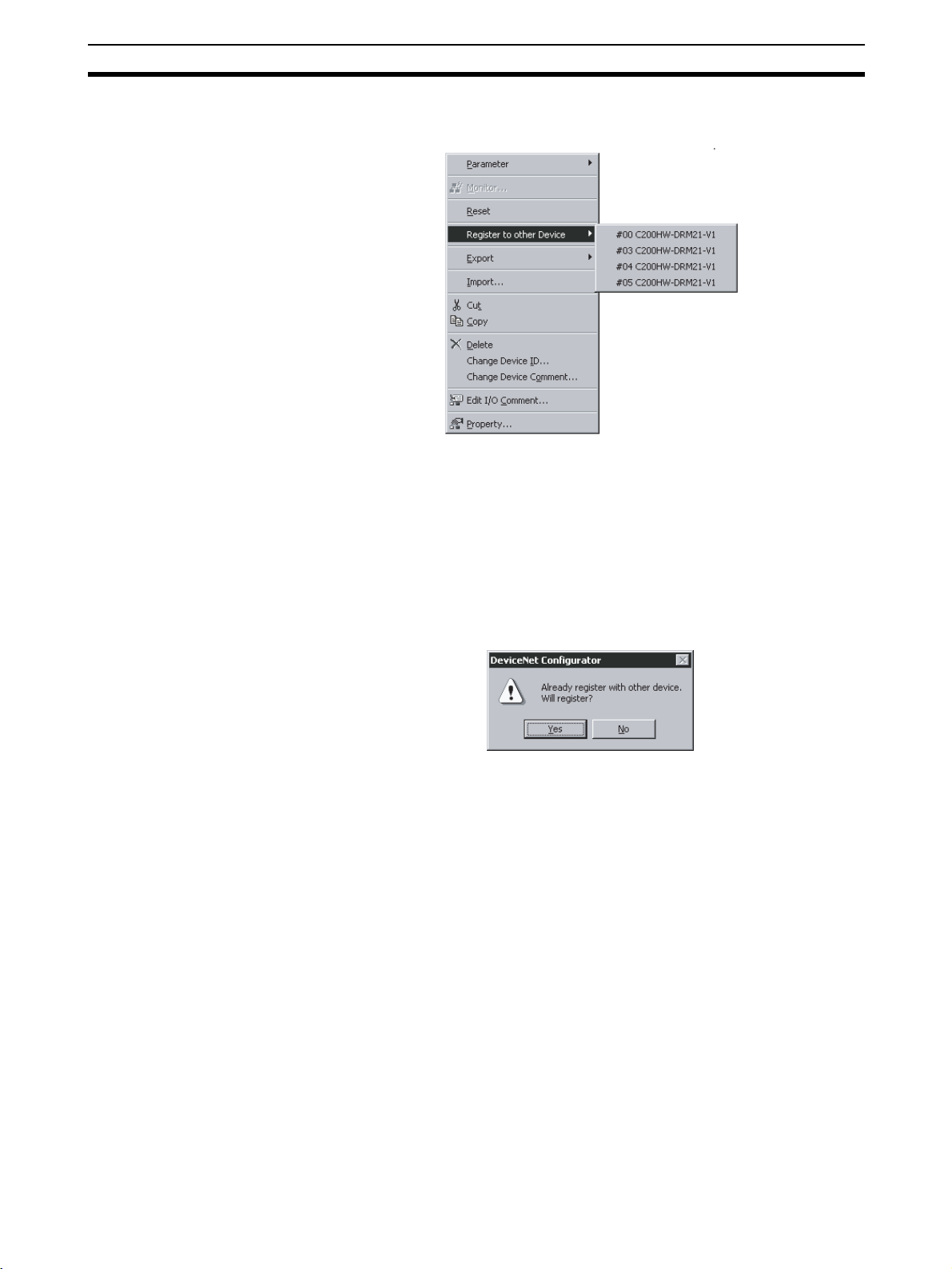
Setting Master Properties Section 4-4
The following master candidates will be displayed in the Register to other
Device Menu.
4. Select the device with which the slave is to be registered.
The slave registered will be automatically added to the scan list of the master and I/O will be allocated.
If the user attempts to register a slave that has already been registered with
another device, the following confirmation window will be displayed. By clicking the Yes Button, the duplicated registration of the slave will be possible.
However, if the registration is duplicated, the slave will only be able to communicate with one device. If the same slave is registered to multiple masters, it
will lead to communications errors.
Registering in the Edit
Device Parameters
Window
Slaves can be added and I/O areas allocated in the Edit Device Parameters
Window. Refer to
page 78 for details.
4-7 Master Parameter Editing Details (Tab Descriptions) on
4-4 Setting Master Properties
This section describes how to set properties for OMRON masters. The
Device – Property Command is used.
4-4-1 CS1W-DRM21 and CJ1W-DRM21
To set the master and slave functions, use the following procedure.
1,2,3... 1. Select the master from the Network Configuration Window on the right.
2. Select Device and Property.
71
Page 91
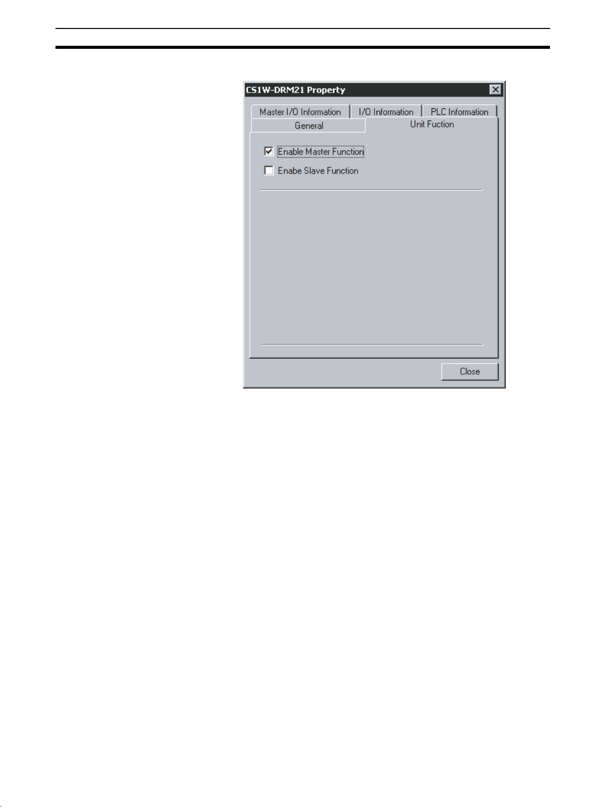
Setting Master Properties Section 4-4
The following window will be displayed. Select the Unit Function Tab.
3. Select Enable Master Function and/or Enable Slave Function.
4-4-2 CVM1-DRM21-V1 or C200HW-DRM21-V1
To set the PLC model on which the Unit is mounted, use the following procedure.
1,2,3... 1. Select the device.
2. Select Device.
3. Select Property.
72
Page 92

Editing Master Parameters Section 4-5
The following window will be displayed. Select the PLC Information Tab.
4. Click the Change Unit Button.
The following window will be displayed.
5. Specify the PLC model. Click the OK Button.
Note When the PLC model is changed, all the settings presently made will be
cleared and default values will be set.
4-5 Editing Master Parameters
Device parameters are classified into master device parameters and slave
device parameters. The following description provides information on how to
edit master device parameters.
The master device parameters that can be edited include slave device I/O
allocations to the master, communication cycle time settings, and connection
settings. The following two methods can be used to edit parameters for the
master.
73
Page 93

Parameter Wizard Section 4-6
Parameter Wizard The Parameter Wizard is an interactive interface that makes I/O allocations
possible in order of node addresses.
Editing Parameters Parameters can be edited to allocate I/O and make settings as required,
including the communication cycle time, connection, and device information
check settings.
The Configurator allows settings, such as the following function settings, for
the OMRON CS1W-DRM21 DeviceNet Unit, CJ1W-DRM21 DeviceNet Unit,
CVM1-DRM21-V1 DeviceNet Master Unit, and C200HW-DRM21-V1
DeviceNet Master Unit.
Function Setting method CS1W-DRM21 C200HW-DRM21-V1 or
Parameter Wizard
(Device - Parameter -
Wizard)
I/O Allocations Parameter Wizard I/O Allocation (OUT) and I/
Communication
Cycle Time
Connections Advanced Setup Button in
Device Information
Compare
Message Timer Message Timer Tab OK No
Slave Function Slave Function Tab OK No
Startup Remote I/O
Communications
Explicit Message
Communications
--- Communication Cycle
Parameter editing
(Device - Parameter -
O Allocation (IN) Tabs
Time Tab
General Tab
General Tab (See note 1.) OK
Edit)
OK OK
OK OK
OK No
OK No
(See note 2.) OK
CVM1-DRM21-V1
Note 1. The same function can be achieved with the setting to enable/disable the
master function.
2. Explicit message communications is possible whether or not registration
has been made on the scan list.
3. Before making device I/O allocations to the master, the device must be
added to the Network Configuration Window, regardless of whether or not
it has been registered as a slave with the master. Refer to 4-1 Adding De-
vices to the Virtual Network to create the network configuration.
4-6 Parameter Wizard
Device - Parameter Wizard
74
• The Parameter Wizard is an interactive function making it possible to allocate I/O with ease.
• This function ensures easy I/O allocations in order of node addresses
beginning with block 1. Each block consists of a maximum of 100 words.
When block 1 is full, the remaining I/O will be allocated to block 2.
Note After I/O allocations are made with the Parameter Wizard, node ad-
The following procedure uses the Parameter Wizard with the CS1W-DRM21/
CJ1W-DRM21 as an example. The same method can be used for the CVM1DRM21-V1 and C200HW-DRM21-V1.
Specify the first address of each block (fixed to 100 words in size), the allocation method (i.e., allocation in blocks of words or minimum required number of
words), and the registration or deletion of slaves.
dresses or I/O allocations can be changed by editing the parameters
individually.
Page 94

Parameter Wizard Section 4-6
Note To make allocations in excess of 100 words per block, use Parame-
ter - Edit.
To allocate I/O of slave devices to the master with the Parameter Wizard, use
the following procedure.
1,2,3... 1. Select the master.
2. Select Device, Parameter, and Wizard.
3. When settings are made with the Parameter Wizard, the present settings
will be cleared and default values will be set. The following confirmation
window will be displayed. Click the Yes Button.
4. The following Scan List Wizard-Set Memory Block’s Start Word Window
will be displayed.
Set the memory area to be used and the start word and click the Next But-
ton. I/O will be automatically allocated to block 1. When block 1 is full, I/O
will be allocated to block 2. Each block consists of a maximum of 100
words.
Note It is not possible to go to the next step if there is any duplication be-
tween blocks or the first word is not within the permissible set range.
5. The Scan list Wizard-Set How to Allocate I/O Date to PLC Memory Block
Window will be displayed.
75
Page 95
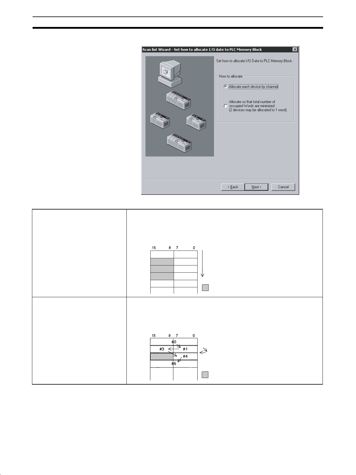
Parameter Wizard Section 4-6
Specify the allocation method and click the Next Button.
Allocate each node by word.
Allocate so that total number of
allocated words are minimized.
The following two allocation methods are supported.
Slaves are always allocated memory starting with the seven rightmost bytes in
the word. Even slaves that require just one byte of I/O memory will be allocated
one word.
Example:
High Low
to to
#0
#1
#3
#4
#6
If there are slaves that require just one byte of I/O memory, they are allocated
the rightmost seven bits or leftmost seven bits so that the total number of
occupied words is minimized.
Example:
High Low
to to
Node address order
: Not used
Node address order
: Not used
76
An allocation example is shown below.
I/O Example:
#00 1 byte
#01 2 bytes
#02 1 bytes
#03 4 bytes
#04 1 byte
#05 1 bytes
Page 96

Parameter Wizard Section 4-6
Allocation in Units of Words
Allocation with Allocated Words Minimized
6. Slave Registration/Deletion
The following Scan List Wizard - Set Memory Block’s Start Word Window
will be displayed.
Specify the slave to be registered with the master and click the Next But-
ton.
High
15 8 7 0
+0CH
+1CH
+2CH
+3CH
+4CH
+5CH
+6CH
High
15 8 7 0
+0CH
+1CH
+2CH
+3CH
+4CH
#02
#05
#01
#03
#03
#01
#03
#03
Low
#00
#02
#04
#05
Low
#00
#04
The devices on the network are shown in the Registered Device List.
To cancel the registration of a device, click the following icon:
The user cannot go to the next step if no devices are registered.
7. The following Scan List Wizard-Allocated Result Window will be displayed
after remote I/O allocations have been made as specified.
77
Page 97

Master Parameter Editing Details (Tab Descriptions) Section 4-7
Click the Finish Button if the displayed details are OK. The Parameter Wiz-
ard will finish. The user can click the Back Button to return to the previous
window.
The displayed details will be set as device parameters.
8. When the Configurator is online, the following window will be displayed.
Click the Yes Button and edit the master parameters. Remote I/O communications according to the new settings will start.
Note Device parameters set with the Parameter Wizard can be edited by individu-
ally if necessary.
4-7 Master Parameter Editing Details (Tab Descriptions)
Device - Parameter Edit
The user can individually edit allocations for remote I/O communications and
make advanced settings, such as the communication cycle time and connection settings. Possible setting items vary with the master model.
The following description provides information on editing individual parameters. Refer to 4-8 Manual I/O Allocations on page 84 and 4-9 Advanced Set-
tings (Connection, Communication Cycle Time, Slave Function Settings, Etc.)
on page 91 for further information on editing parameters manually.
To edit the parameters, use the following procedure.
78
1,2,3... 1. Select the device for which parameters are to be edited.
2. Select Device, Parameter, and Edit.
3. The Edit Device Parameters Window will be displayed.
Page 98
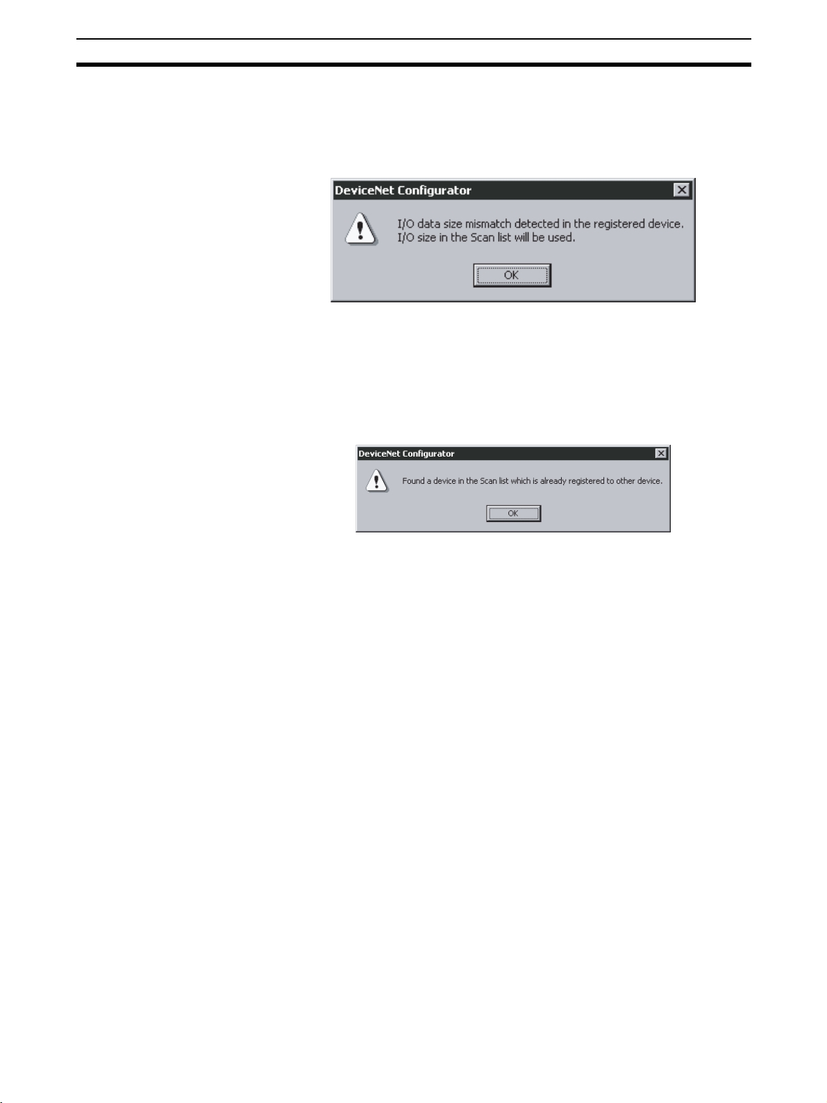
Master Parameter Editing Details (Tab Descriptions) Section 4-7
Note a) If the I/O size of the device displayed in the Network Configuration
Window does not coincide with the I/O data size of the device registered with the scan list, the following warning dialog will be displayed along with the Edit Device Parameters Window. In this
case, the I/O size in the scan list will take priority.
If an EDS file has not been installed in the slave, obtain the EDS
file and install it. Also, set the correct I/O size in all slaves that require changes in the I/O size.
b) If the slave device registered with the scan list has already been
registered with another master, the following warning will be displayed along with the Edit Device Parameters Window.
Revise the slaves registered in the scan list.
4-7-1 Edit Device Parameters on CS1W-DRM21/CJ1W-DRM21
Note When the CS1W-DRM21/CJ1W-DRM21 DeviceNet Unit is used, select the
device and then select Device, and Property and turn ON Enable Master
Function in the Properties Dialog Box.
79
Page 99

Master Parameter Editing Details (Tab Descriptions) Section 4-7
The following window will be displayed when the CS1W-DRM21/CJ1WDRM21 is selected.
The Edit Device Parameters Window consists of the following six tabs.
Tab Description
General Registers the device with the scan list and makes I/O allocations automatically.
I/O Allocation (OUT) Allocates the output data and sets the output memory block for the CPU Unit with the advanced
I/O Allocation (IN) Allocates the input data and sets the input memory block in the CPU Unit with the advanced setup
Communication
Cycle Time
Slave Function Makes necessary settings that enable the slave function.
Message Timer Makes monitor timer settings for message communications (both explicit and FINS message
setup function.
function.
Sets the communication cycle time.
communications).
80
Page 100
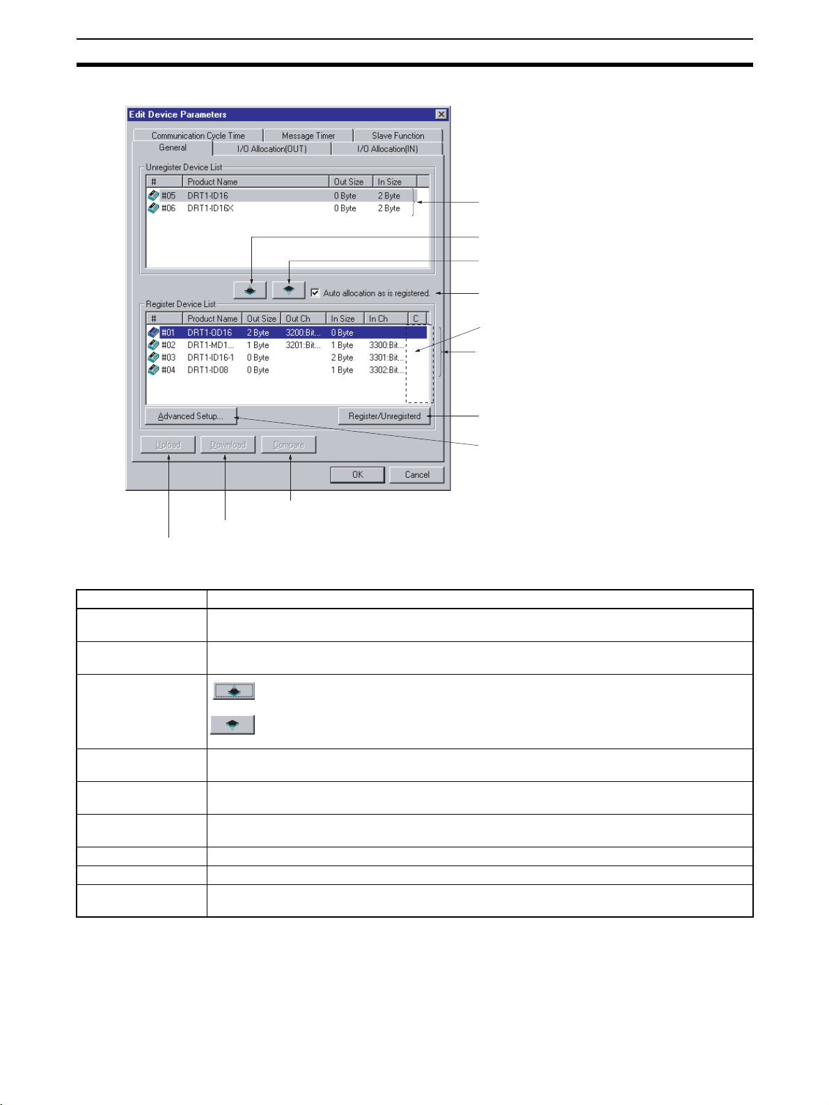
Master Parameter Editing Details (Tab Descriptions) Section 4-7
General Tab of CS1W-DRM21/CJ1W-DRM21
Unregistered Device List
Upload par
Item Description
Unregistered Device
List
Registered Device
List
Device Register and
Unregister Buttons
Download par
ameters
Usable only when online.
Compare par
ameters
Usable only when online.
ameters
Device Register b
Device Unregister b
A
utomatic allocation as registered
An asterisk (*) appears when the slave
is registered to allow explicit message only.
Registered De
Register/Unregistered Button
anced Setup Button
Adv
Usable only when online.
utton
utton
vice List
Displays unregistered devices. Unregistered devices refer to slaves that are displayed in the
Network Configuration Window but have not been registered with a master.
Displays slaves that are presently registered with a master.
By pressing this button, the selected device will move from the Unregistered Device
List to the Registered Device List.
By pressing this button, the device will move from the Registered Device List to the
Unregistered Device List.
Auto allocation as is
registered
Register/
Unregistered Button
Advanced Setup
Check this box when registering the slaves with the master in the Edit Device Parameters Window
so that the slaves will be allocated to an unused area in blocks of words in order of registration.
Click this button to unregister the I/O allocation of the selected slaves or to make the I/O
reallocation of the slaves in the order of earlier addresses.
Click this button to set the connections or display the device information.
Button
Upload Uploads the parameters of the network device online.
Download Downloads the parameters to the network device on line.
Compare Compares the parameters of the selected network device with the parameters stored in the
Configurator.
81
 Loading...