

Omron 3G3RX2-A2037, 3G3RX2-A2022, 3G3RX2-A2004, 3G3RX2-A4007, 3G3RX2-A4015 Instruction Manual
...Page 1
高機能型汎用インバータ
RX2シリーズ(形3G3RX2-□□□□□)
取扱説明書
このたびは、インバータ形3G3RX2シリーズをお買い求めいただきまして、誠にありがとうございます。
この製品を安全に正しくご使用いただくために、お使いになる前に、この取扱説明書と安全上のご注
意および下記のマニュアルを熟読し、機器の知識、安全上の情報、注意事項のすべてについて習熟し
てから使用してください。また、お読みになったあとも、お使いになるときにはいつでも見られるように、
本書とユーザーズマニュアルは、最終的にお使いになる方のお手元にも届けられるよう、お取り計らい
をお願いします。
ユーザーズマニュアル SBCE -4 37
OMRONCorporation2019AllRightsReserved.
PIM2824133-4A
NT3171
Page 2

ご承諾事項
ご承諾事項
「当社商品」について特別の合意がない場合には、お客様のご購入先にかかわらず、本ご承諾事項記
載の条件を適用いたします。
定義
本ご承諾事項中の用語の定義は次のとおりです。
• 「当社商品」:「当社」の FA システム機器、汎用制御機器、センシング機器、電子・機構部品
• 「カタログ等」:「当社商品」に関する、ベスト制御機器オムロン、電子・機構部品総合カタロ
グ、その他のカタログ、仕様書、取扱説明書、マニュアル等であって電磁的方法で提供される
ものも含みます。
• 「利用条件等」:「カタログ等」に記載の、「当社商品」の利用条件、定格、性能、動作環境、取
り扱い方法、利用上の注意、禁止事項その他
• 「お客様用途」:「当社商品」のお客様におけるご利用方法であって、お客様が製造する部品、電
子基板、機器、設備またはシステム等への「当社商品」の組み込み、または利用を含みます。
• 「適合性等」:「お客様用途」での「当社商品」の (a) 適合性、(b) 動作、(c) 第三者の知的財産
の非侵害、(d) 法令の遵守および (e) 各種規格の遵守
記載事項のご注意
「カタログ等」の記載内容については次の点をご理解ください。
• 定格値および性能値は、単独試験における各条件のもとで得られた値であり、各定格値および
性能値の複合条件のもとで得られる値を保証するものではありません。
• 参考データはご参考として提供するもので、その範囲で常に正常に動作することを保証するも
のではありません。
• 利用事例はご参考ですので、「当社」は「適合性等」について保証いたしかねます。
• 「当社」は、改善や当社都合等により、「当社商品」の生産を中止し、または「当社商品」の仕
様を変更することがあります。
ご利用にあたってのご注意
ご採用およびご利用に際しては次の点をご理解ください。
• 定格・性能ほか「利用条件等」を遵守しご利用ください。
• お客様ご自身にて「適合性等」をご確認いただき、「当社商品」のご利用の可否をご判断ください。
「当社」は「適合性等」を一切保証いたしかねます。
• 「当社商品」がお客様のシステム全体の中で意図した用途に対して、適切に配電・設置されてい
ることをお客様ご自身で、必ず事前に確認してください。
• 「当社商品」をご使用の際には、(i) 定格および性能に対し余裕のある「当社商品」のご利用、冗長
設計などの安全設計、(ii) 「当社商品」が故障しても、「お客様用途」の危険を最小にする安全設計、
(iii) 利用者に危険を知らせるための、安全対策のシステム全体としての構築、(iv) 「当社商品」お
よび「お客様用途」の定期的な保守、の各事項を実施してください。
• 「当社」は DDoS 攻撃(分散型 DoS 攻撃)、コンピュータウイルスその他の技術的な有害プログ
ラム、不正アクセスにより、「当社商品」、インストールされたソフトウェア、またはすべての
コンピュータ機器、コンピュータプログラム、ネットワーク、データベースが感染したとして
も、そのことにより直接または間接的に生じた損失、損害その他の費用について一切責任を負
わないものとします。
2
Page 3

ご承諾事項
お客様ご自身にて、①アンチウイルス保護、②データ入出力、③紛失データの復元、④「当社商
品」またはインストールされたソフトウェアに対するコンピュータウイルス感染防止、⑤「当社
商品」に対する不正アクセス防止についての十分な措置を講じてください。
• 「当社商品」は、一般工業製品向けの汎用品として設計製造されています。従いまして、次に掲
げる用途での使用は意図しておらず、お客様が「当社商品」をこれらの用途に使用される際には、
「当社」は「当社商品」に対して一切保証をいたしません。ただし、次に掲げる用途であっても
「当社」の意図した特別な商品用途の場合や特別の合意がある場合は除きます。
(a) 高い安全性が必要とされる用途(例:原子力制御設備、燃焼設備、航空・宇宙設備、鉄道設
備、昇降設備、娯楽設備、医用機器、安全装置、その他生命・身体に危険が及びうる用途)
(b) 高い信頼性が必要な用途(例:ガス・水道・電気等の供給システム、24 時間連続運転シス
テム、決済システムほか権利・財産を取扱う用途など)
(c) 厳しい条件または環境での用途(例:屋外に設置する設備、化学的汚染を被る設備、電磁
的妨害を被る設備、振動・衝撃を受ける設備など)
(d) 「カタログ等」に記載のない条件や環境での用途
• 上記の (a) から (d) に記載されている他、「本カタログ等記載の商品」は自動車(二輪車含む。
以下同じ)向けではありません。自動車に搭載する用途には利用しないで下さい。自動車搭載
用商品については当社営業担当者にご相談ください。
保証条件
「当社商品」の保証条件は次のとおりです。
• 保証期間 ご購入後 1 年間といたします。
(ただし「カタログ等」に別途記載がある場合を除きます。)
• 保証内容 故障した「当社商品」について、以下のいずれかを「当社」の任意の判断で実施し
ます。
(a) 当社保守サービス拠点における故障した「当社商品」の無償修理
(ただし、電子・機構部品については、修理対応は行いません。)
(b) 故障した「当社商品」と同数の代替品の無償提供
• 保証対象外 故障の原因が次のいずれかに該当する場合は、保証いたしません。
(a)「当社商品」本来の使い方以外のご利用
(b)「利用条件等」から外れたご利用
(c) 本ご承諾事項「ご利用にあたってのご注意」に反するご利用
(d)「当社」以外による改造、修理による場合
(e)「当社」以外の者によるソフトウェアプログラムによる場合
(f) 「当社」からの出荷時の科学・技術の水準では予見できなかった原因
(g) 上記のほか「当社」または「当社商品」以外の原因(天災等の不可抗力を含む)
責任の制限
本ご承諾事項に記載の保証が、「当社商品」に関する保証のすべてです。
「当社商品」に関連して生じた損害について、「当社」および「当社商品」の販売店は責任を負い
ません。
輸出管理
「当社商品」または技術資料を、輸出または非居住者に提供する場合は、安全保障貿易管理に関す
る日本および関係各国の法令・規制を遵守ください。お客様が法令・規則に違反する場合には、
「当社商品」または技術資料をご提供できない場合があります。
3
Page 4
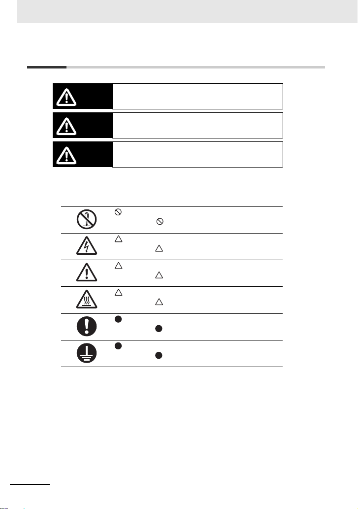
安全上のご注意
危険
警告
注意
安全上のご注意
正しい取り扱いをしなければ、この危険のために、時 に死亡に至っ
たり、重傷を負う場合も起こり得ます。
また、同様に深刻な物的損害を受けるおそれがありま す。
正しい取り扱いをしなければ、この危険のために、軽 傷や中程度の
傷害を負ったり、万一の場合には重症や死亡に至るお それがありま
す。また、同様に重大な物的損害を受けるおそれがあ ります。
正しい取り扱いをしなければ、この危険のために、時 に軽傷や中程
度の傷害を負ったり、あるいは物的損害を受けるおそ れがあります。
図記号の説明
本文中に図記号を用いた注記を記載しています。
本内容にも十分注意をはらい、必ず守ってください。
記号は禁止(してはいけないこと)を示します。
具体的な内容は、 の中や近くに絵や文章で示します。
左図の場合は、「分解禁止」を示します。
記号は危険、注意を示します。
具体的な内容は、 の中や近くに絵や文章で示します。
左図の場合は、「感電による危険」を示します。
記号は危険、注意を示します。
具体的な内容は、 の中や近くに絵や文章で示します。
左図の場合は、「特定しない一般的な危険」を示します。
記号は危険、注意(警告を含む)を意味しています。
具体的な内容は、 の中と文章で示します。
左図の場合は、「高温注意」を示します。
記号は強制(必ず守ること)を示します。
具体的な内容は、 の中や近くに絵や文章で示します。
左図の場合は、「一般的な強制事項」を示します。
記号は強制(必ず守ること)を示します。
具体的な内容は、 の中と文章で示します。
左図の場合は、「必ずアース接地すること」を示します。
4
Page 5

万一の場合、感電による重度の傷害が起こるおそれがあります。
警告
*1. 10 分 : 形 3G3RX2-A2004 〜 -A2220 および形 3G3RX2-A4007 〜 A4220
*2. 15 分 : 形 3G3RX2-A2300 〜 -A2550、形 3G3RX2-A4300 〜 -A4550、-B4750、
-B4900、-B411K、-B413K
入力電源 OFFを確認してから正しく配線してください。
万一の場合、感電による重度の傷害が起こるおそれがあります。
配線作業は、電気工事の専門家が行ってください。
万一の場合、感電による重度の傷害が起こるおそれがあります。
配線変更、スライドスイッチ(SW1 〜 SW6)の変更、オペレータ・オプ
ション類の脱着、冷却ファンの交換はインバータの入力電源を OFFにして
から行ってください。
万一の場合、感電・発火による重度の傷害が起こるおそれがあります。
接地端子は必ずアースしてください。
(200V 級 :D 種接地、400V 級 :C 種接地)
万一の場合、感電による重度の傷害が起こるおそれがあります。
通電中および電源遮断後 15 分以内 *1*2 は端子台カバーを外さないでくだ
さい。
万一の場合、感電による重度の傷害が起こるおそれがあります。
濡れた手でオペレータ、スイッチ類を操作しないでください。
万一の場合、感電による重度の傷害が起こるおそれがあります。
緊急遮断入力機能が働いた状態になっても、主電源が遮断されたわけでは
ありません。
製品の確認は、インバータの入力電源を OFFにしてから行ってください。
やけどのおそれがあります。
通電中や電源遮断後のしばらくの間は、インバータのフィン、制動抵抗器、
モータなどは高温になる場合がありますので触れないでください。
安全上のご注意
5
Page 6

安全上のご注意
注意
保守や点検、部品交換を行う際は、安全を確保したあとで行ってください。
軽度の発火、発熱、機器破損がまれに起こるおそれがあります。
端子(PD/+1,P/+,N/ −)に抵抗器を直接接続しないでください
軽度の傷害がまれに起こるおそれがあります。
安全を確保するための停止装置を設置してください。
※ 保 持用に選定されたブレーキは安全を確保するための停止装置ではあり
ません
制動抵抗器や回生制動ユニットの発熱により、中程度のやけどがまれに起
こるおそれがあります。
必ず指定された制動抵抗器や回生制動ユニットを使用し、制動抵抗器を使
用する場合には、抵抗器の温度を監視するサーマルリレーを設置してくだ
さい。
また、制動抵抗器や回生制動ユニットの異常過熱時にインバータの電源を
OFF するシーケンスを組んでください。
製品内部には高電圧部分があり、短絡させると製品の破損や物的損害がま
れに起こるおそれがあります。設置や配線時には切り粉やリード線くずな
どの金属物が製品内部に入らないようにカバーをつけるなどの処置を行っ
てください。
負荷の短絡により物的損害がまれに起こるおそれがあります。
インバータの電源側にはインバータ容量に応じた配線用遮断器(MCCB)
を設置するなどの安全対策を施してください
けがのおそれがあります。
分解や修理、改造は行わないでください。
立ち上げ時、調整時、メンテナンス時、交換時にパラメータを誤って設定
すると予期せぬ動作が起きるおそれがあります。
出力端子機能が出力中に、DriveProgramming が停止すると、出力状態を
保持したままになりますので、周辺機器を停止させるなど安全対策を施し
てください。
6
Page 7

安全上の要点
設置・保管
下記環境下での保管および使用は避けてください。
• 日光が直接当たる場所
• 周囲温度が仕様を超える場所
• 相対湿度が仕様を超える場所
• 温度の変化が急激で結露するような場所
• 腐食性ガス、可燃性ガスのある場所
• 可燃物またはその近くの場所
• ちり、ほこり、塩分、鉄粉が多い場所
• 水、油、薬品などの飛まつがかかる場所
• 本体に直接振動や衝撃が伝わる場所
輸送・設置・配線
• 部品の故障、製品故障の原因となります。強い衝撃を与えたり、落下させたりしないでください。
• 運搬時は、フロントカバー・端子台カバーを持たずにフィンを持ってください。
• インバータの入力電源定格電圧と、交流電源の電圧が一致していることを確認してください。
• 製品が破損しますので、制御入出力端子に交流電源を接続しないでください。
• 端子台のねじは確実に締め付けてください。また、配線は本体を据え付けてから行ってください。
• 本製品の出力 (U、V、W) に三相誘導モータ以外の負荷を接続しないでください。
• 次のような場所で使用する際は、遮断対策を十分に行ってください。機器破損の原因となります。
• 静電気などによるノイズが発生する場所
• 強い磁界が生じる場所
• 電源線が近くを通る場所
• DriveProgramming を使用する場合は、プログラムデータが正常にダウンロードできたことを確認
してから動作を開始してください。
運転・調整
• 本製品は低速から高速までの設定ができますので、使用するモータ設備の許容範囲を十分確認した
あとで運転を行ってください。
• 保持用にブレーキが必要な場合は、別に用意してください。
• DriveProgramming で時刻機能を使用して制御を行う場合、LCD オペレータの電池消耗で予期せ
ぬ動作が起きるおそれがあります。
電池消耗は、[E042]RTC エラーで検出し、インバータまたはプログラムを停止させるなどの対策
を行ってください。
LCD オペレータが取り外されたり、断線したりした場合、DriveProgramming は時刻機能で待機
状態になります。
• 運転信号を入れたままアラームリセットを行うと突然始動することがありますので、運転信号が切
れていることを確認してからアラームリセットを行ってください。
• 瞬停・不足電圧減速停止後や、リセット時に再始動となる設定 (bA-30,bb-20,bb-21) を行うと、
電源復帰後に突然再始動しますので注意してください。
• オペレータのストップボタンは機能設定したときだけ有効ですので、緊急停止スイッチは別に用意
してください。
• 通電中に信号チェックを行い、誤って制御入力端子に電圧が印加されるとモータが突然動き出すこ
とがあります。信号チェックを行う際は安全を確かめて行ってください。
• 運転時にモータの回転方向、異常音、振動を確認してください。
安全上の要点
7
Page 8

安全上の要点
保守・点検
• コンデンサの寿命は周囲温度に影響されます。ユーザーズマニュアルに記載されている製品寿命
カーブをご覧ください。コンデンサが寿命に達し、製品として機能を果たさなくなった場合には、
本体の交換が必要となります。
• LCD オペレータで不要になった電池の廃棄については、地方自治体により規制を受ける場合があ
ります。それぞれの自治体規制に従って廃棄してください。電池を廃棄する際は、電池をテープな
どで絶縁してから廃棄してください。
リチウム一次電池(過塩素酸塩含有率が 6ppb 以上)を組み込んだ製品が米国・カリフォルニア
州へ輸出・経由される場合、次の表示が義務化されています。
PerchlorateMaterial-specialhandlingmayapply.
Seewww.dtsc.ca.gov/hazardouswaste/perchlorate
リチウム一次電池が組み込まれた貴社製品を米国・カリフォルニア州へ輸出される場合は、貴社
製品の梱包箱または輸送箱などに上記表示を行っていただくようお願いします。
• 電池は液漏れ、破裂、発熱、発火などのおそれがありますので、+、−の短絡、充電、分解、加
熱、火への投入、強い衝撃を与えることなどは絶対に行わないでください。また、床に落下させる
などして強い衝撃をあたえてしまった電池は、液漏れするおそれがありますので絶対に使用しない
でください。
• 電池の交換は熟練した技術者によって行われることが UL 規格で定められています。交換作業は熟
練した技術者がご担当ください。また、本マニュアルに記載された方法で交換してください。
• LCD オペレータの表示が寿命で認識できなくなった場合は、LCD オペレータを交換してください。
8
Page 9

使用上の注意
WEEE 指令に従った廃棄をお願いするマークです。
取り付け
取付方向は縦長方向で壁取り付けとしてください。
また、取り付け壁の材質は金属板等の不燃材としてください。
設置・配線
ご使用のエンコーダ用電源か製品の定格電圧(DC + 12V または DC + 5V)と一致していることを
確認してください。
再始動選択機能
再始動選択機能(bb-24)トリップリトライ機能(bb-28)を使用すると、アラーム停止後に突然始
動しますので、近寄らないでください。
保守・部品の交換
• インバータは数多くの部品より構成されており、これらの部品がすべて正常に動作しなければ本来
の機能を発揮することはできません。
このため、定期的な点検により、部品や装置が不具合に至る前兆をできるだけ早い時期に発見し、
処置を行う必要があります。
また、これらの部品は無期限に継続して使用できるものではなく、正常な使用状態においても、そ
の種類により定まる或る年数、即ち耐用年数を経過すると特性の変化や動作不良を起こし易くなる
ものであり、一定期間を経過する毎に部品の交換を行わねばインバータの特性の変化や故障の発生
を防止することはできません。(JEMA 発行「汎用インバータ定期点検のおすすめ」から引用)
• 冷却ファンが寿命に達したときは、修理を依頼してください。
製品の廃棄
本製品を廃棄する際は、条例などの規則に従ってください。
使用上の注意
9
Page 10
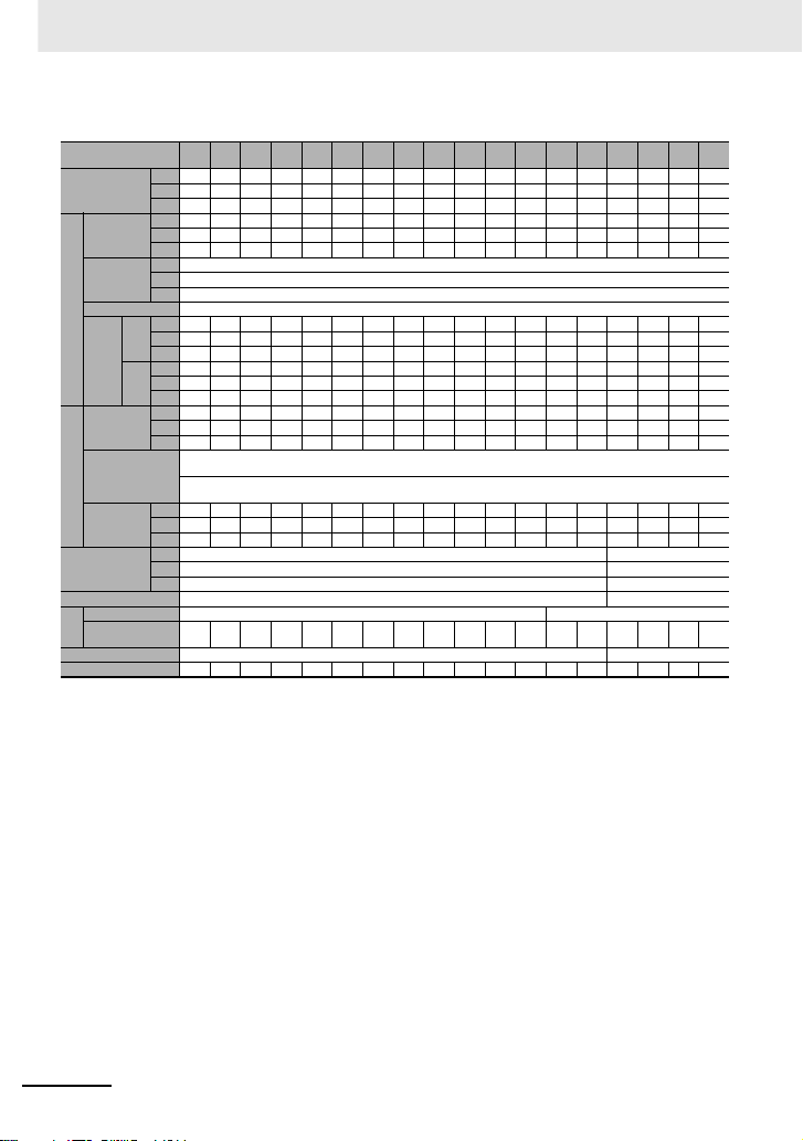
形式基準
最大適用モータ容量(ND)
電圧クラス
保護構造
形3G3RX2-A2055
004
007
015
022
037
055
075
110
150
185
220
300
370
450
550
750
900
11K
13K
0.4kW
0.75kW
1.5kW
2.2kW
3.7kW
5.5kW
7.5kW
11kW
15kW
18.5kW
22kW
30kW
37kW
45kW
55kW
75kW
90kW
110kW
132kW
24三相 AC200V(200V 級)
三相 AC400V(400V 級)
ABIP20*/ULopentype
IP00/ULopentype
* 社内試験による自己宣言です。
形式基準
10
Page 11
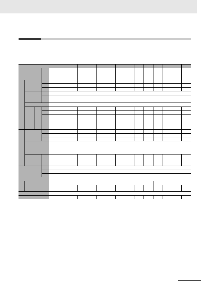
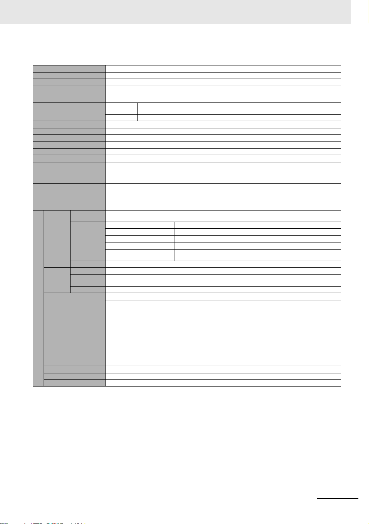
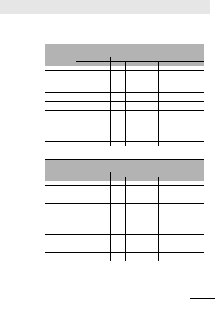
仕様
仕様
■仕様
200V 級
形 3G3RX2-A2 □□□□□
適用モータ
(4 極)
容量(kW)
定格出力
電流(A)
過負荷
電流定格
出
定格出力電圧 三相(3 線)200 〜240V(受 電電圧に依存します)
力
定格
容量
(kVA)
定格入力
電流(A)*1
入
定格入力
力
交流電圧
電源設備
容量(kVA)
*2
キャリア
周波数
変更範囲 *3
モータ始動トルク *4 200%/0.3Hz
回生制動 制動抵抗動作回路内蔵(放電抵抗別置) 回生制動ユニット別置
制
接続可能な
動
最小抵抗値(Ω)
保護構造 IP20*5/ULopentype
概略質量(kg) 3333366610101022333347
*1. 定格入力電流は、定格電流出力時の値です。電源側のインピーダンス(配線、ブレーカ、入 力リアクトルオプションなど)により値が変わります。定格
銘板の数値と異なりますが、この電流値を参考に余裕をもって周辺機器を選定してください。
*2. 電源設備容量は、220V 出力の定格電流出力時の値です。電源側のインピーダンス(配線、ブレーカ、入力リアクトルオプションなど)により値が変わ
ります。
*3. キャリア周波数[bb101]/[bb201]の設定は、表記に従って定格設定に、内部で制限がかかります。また、キャリア周波数[bb101]/[bb201]
の設定は、(駆動する最大出力周波数 ×10)Hz 以上になるように設定してください。誘導モータ(IM)制御の場合、V/f 制御以外の制御は、キャリア
周波数を 2kHz 以上に設定してください。同期モータ(SM)/ 永久磁石モータ(PMM)制御の場合、キャリア周波数を 8kHz 以上に設定してくださ
い。
*4. 標準モータで ND 定格におけるセンサレスベクトル制御適用時の値。トルク特性は、制御方式やご使用のモータにより異なる場合があります。
*5. 社内試験による自己宣言です。
A2004 A2007 A2015 A2022 A2037 A2055 A2075 A2110 A2150 A2185 A2220 A2300 A2370 A2450 A2550
VLD 0.75 1.5 2.2 3.7 5.5 7.5 11 15 18.5 22 30 37 45 55 75
LD 0.75 1.5 2.2 3.7 5.5 7.5 11 15 18.5 22 30 37 45 55 75
ND 0.4 0.75 1.5 2.2 3.7 5.5 7.5 11 15 18.5 22 30 37 45 55
VLD 4.4 8.0 10.4 15.6 22.8 33.0 46.0 60.0 80.0 93.0 124 153 185 229 295
LD 3.7 6.3 9.4 12.0 19.6 30.0 40.0 56.0 73.0 85.0 113 140 169 210 270
ND 3.2 5.0 8.0 11.0 17.5 25.0 32.0 46.0 64.0 76.0 95.0 122 146 182 220
VLD 110%60sec/120%3sec
LD 120%60sec/150%3sec
ND 150%60sec/200%3sec
VLD 1.5 2.8 3.6 5.4 7.9 11.4 15.9 20.8 27.7 32.2 43.0 53.0 64.1 79.3 102.2
200
LD 1.3 2.2 3.3 4.2 6.8 10.4 13.9 19.4 25.3 29.4 39.1 48.5 58.5 72.7 93.5
V
ND 1.1 1.7 2.8 3.8 6.1 8.7 11.1 15.9 22.2 26.3 32.9 42.3 50.6 63.0 76.2
VLD 1.8 3.3 4.3 6.5 9.5 13.7 19.1 24.9 33.3 38.7 51.5 63.6 76.9 95.2 122.6
240
LD 1.5 2.6 3.9 5.0 8.1 12.5 16.6 23.3 30.3 35.3 47.0 58.2 70.3 87.3 112.2
V
ND 1.3 2.1 3.3 4.6 7.3 10.4 13.3 19.1 26.6 31.6 39.5 50.7 60.7 75.7 91.5
VLD 5.2 9.5 12.4 18.6 27.1 39.3 54.8 71.4 95.2 110.7 147.6 182.1 220.2 272.6 351.2
LD 4.4 7.5 11.2 14.3 23.3 35.7 47.6 66.7 86.9 101.2 134.5 166.7 201.2 250.0 321.4
ND 3.8 6.0 9.5 13.1 20.8 29.8 38.1 54.8 76.2 90.5 113.1 145.2 173.8 216.7 261.9
VLD 2.0 3.6 4.7 7.1 10.3 15.0 20.9 27.2 36.3 42.2 56.3 69.4 83.9 103.9 133.8
LD 1.7 2.9 4.3 5.4 8.9 13.6 18.1 25.4 33.1 38.6 51.3 63.5 76.7 95.3 122.5
ND 1.5 2.3 3.6 5.0 7.9 11.3 14.5 20.9 29.0 34.5 43.1 55.3 66.2 82.6 99.8
VLD 0.5 〜 10.0kHz
LD 0.5 〜 12.0kHz
ND 0.5 〜 16.0kHz
50 50 35 35 35 16 10 10 7.5 7.5 5 - - - -
制御電源:電源単相200 〜 240V/ 許容変動幅 170 〜264V、
50Hz(許容変動幅 47.5 〜 52.5Hz)/60Hz(許容変動幅 57 〜 63Hz)
主回路電源:三相(3 線)200 〜 240V/ 許容変動幅 170 〜 264V、
50Hz(許容変動幅 47.5 〜 52.5Hz)/60Hz(許容変動幅 57 〜 63Hz)
11
Page 12
仕様
400V 級
機種略号(形式)
3G3RX2- □□□□□
適用モータ
(4 極)
容量(kW)
定格出力
電流(A)
過負荷
電流定格
出
定格出力電圧 三相(3 線)380 〜 500V(受電電圧に依存します)
力
定格
容量
(kVA)
定格入力
電流(A)*1
入
定格入力
力
交流電圧
電源設備
容量(kVA)
*2
キャリア
周波数範囲 *3
モータ始動トルク *4 200%/0.3Hz 180%/0.3Hz
回生制動 制動抵抗動作回路内蔵(放電抵抗別置) 回生制動ユニット別置
制
接続可能な
動
最小抵抗値(Ω)
護構造 IP20*5/ULopentype IP00/ULopentype
概略質量(kg) 3 3 3 3 6 6 6 8.5 8.5 8.5 22 31 31 31 41 41 53 53
*1. 定格入力電流は、定格電流出力時の値です。電源側のインピーダンス(配線、ブレー カ、入力リアクトルオプションなど)により値が変わります。定格
銘板の数値と異なりますが、この電流値を参考に余裕をもって周辺機器を選定してください。
*2. 電源設備容量は、440V 出力の定格電流出力時の値です。電源側のインピーダンス(配線、ブレーカ、入力リアクトルオプションなど)により値が変わ
ります。
*3. キャリア周波数[bb101]/[bb201]の設定は、表記に従って定格設定に、内部で制限がかかります。また、キャリア周波数[bb101]/[bb201]
の設定は、(駆動する最大出力周波数 ×10)Hz 以上になるように設定してください。誘導モータ(IM)制御の場合、V/f 制御以外の項目は、キャリア
周波数を 2kHz 以上に設定してください。同期モータ(SM)/ 永久磁石モータ(PMM)制御の場合、キャリア周波数を 8kHz 以上に設定してくださ
い。
*4. 標準モータで ND 定格におけるセンサレスベクトル制御適用時の値。トルク特性は、制御方式やご使用のモータにより異なる場合があります。
*5. 社内試験による自己宣言です。
A4007 A4015 A4022 A4037 A4 055 A4075 A4110 A4150 A4185 A4220 A4300 A4370 A4450 A455 0 B4750 B4900
VLD 1.5 2.2 3.7 5.5 7.5 11 15 18.5 22 30 37 45 55 75 90 110 132 160
LD 1.5 2.2 3.7 5.5 7.5 11 15 18.5 22 30 37 45 55 75 90 110 132 160
ND 0.75 1.5 2.2 3.7 5.5 7.5 11 15 18.5 22 30 37 45 55 75 90 110 132
VLD 4.1 5.4 8.3 12.6 17.5 25.0 31.0 40.0 47.0 62.0 77.0 93.0 116 147 176 213 252 316
LD 3.1 4.8 6.7 11.1 16.0 22.0 29.0 37.0 43.0 57.0 70.0 85.0 105 135 160 195 230 290
ND 2.5 4.0 5.5 9.2 14.8 19.0 25.0 32.0 39.0 48.0 61.0 75.0 91.0 112 150 180 217 260
VLD 110%60sec/120%3sec
LD 120%60sec/150%3sec
ND 150%60sec/200%3sec
VLD 2.8 3.7 5.8 8.7 12.1 17.3 21.5 27.7 32.6 43.0 53.3 64.4 80.4
400V
LD 2.1 3.3 4.6 7.7 11.1 15.2 20.1 25.6 29.8 39.5 48.5 58.9 72.7 93.5
ND 1.7 2.8 3.8 6.4 10.3 13.2 17.3 22.2 27.0 33.3 42.3 52.0 63.0 77.6
VLD 3.6 4.7 7.2 10.9 15.2 21.7 26.8 34.6 40.7 53.7 66.7 80.5
500V
LD 2.7 4.2 5.8 9.6 13.9 19.1 25.1 32.0 37.2 49.4 60.6 73.6 90.9
ND 2.2 3.5 4.8 8.0 12.8 16.5 21.7 27.7 33.8 41.6 52.8 65.0 78.8 97.0
VLD 4.9 6.4 9.9 15.0 20.8 29.8 36.9 47.6 56.0 73.8 91.7
LD 3.7 5.7 8.0 13.2 19.0 26.2 34.5 44.0 51.2 67.9 83.3
ND 3.0 4.8 6.5 11.0 17.6 22.6 29.8 38.1 46.4 57.1 72.6 89.3
VLD 3.7 4.9 7.5 11.4 15.9 22.7 28.1 36.3 42.6 56.3 69.9 84.4
LD 2.8 4.4 6.1 10.1 14.5 20.0 26.3 33.6 39.0 51.7 63.5 77.1 95.3
ND 2.3 3.6 5.0 8.3 13.4 17.2 22.7 29.0 35.4 43.5 55.3 68.0 82.6
VLD 0.5 〜 10.0kHz 0.5 〜 8.0kHz
LD 0.5 〜 12.0kHz 0.5 〜 8.0kHz
ND 0.5 〜 16.0kHz 0.5 〜 10.0kHz
100 100 100 70 70 35 35 24 24 20 15 15 - - - - - -
制御電源:電源単相380 〜 500V(許容変動幅 323 〜 550V)、
50Hz(許容変動幅 47.5 〜52.5Hz)/60Hz(許容変動幅 57 〜 63Hz)
主回路電源:三相(3 線)380 〜 500V(許容変動幅 323 〜 550V)、
50Hz(許容変動幅 47.5 〜52.5Hz)/60Hz(許容変動幅 57 〜 63Hz)
101.8 121.9 147.6 174.6 218.9
110.9 135.1 159.3 200.9
103.9 124.7 150.3 180.1
100.5 127.3 152.4 184.5 218.2 273.7
116.9 138.6 168.9 199.2 251.1
110.7 138.1 175.0 209.5 253.6 300.0 376.2
101.2 125.0 160.7 190.5 232.1 273.8 345.2
129.9 155.9 187.9 225.2
108.3 133.3 178.6 214.3 258.3 309.5
105.2 133.4 159.7 193.2 228.6 286.7
122.5 145.2 176.9 208.7 263.1
101.6 136.1 163.3 196.9 235.9
B411K B413K
12
Page 13
仕様
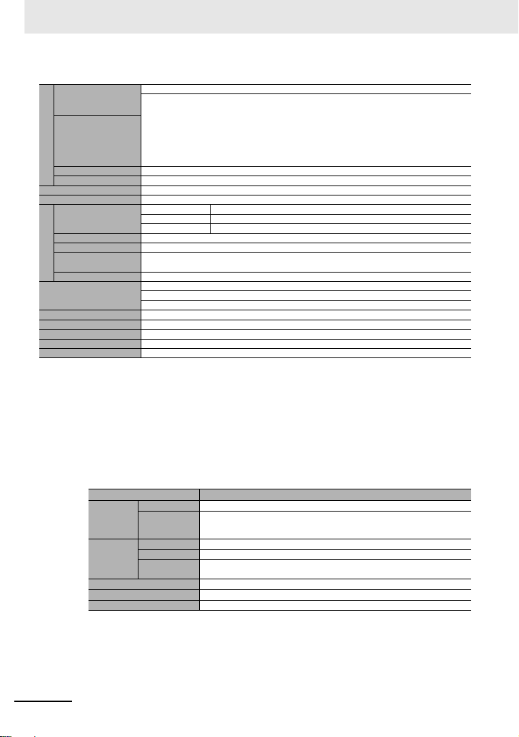
共通仕様
制御方式(モータへの出力) 正弦波 PWM 制御電圧出力(線間正弦波変調)
出力周波数範囲*1 0.00 〜 590.00Hz
周波数精度 最高周波数に対して、デジタル指令 ±0.01%、アナログ指令 ±0.2%(25 ℃ ±10 ℃)
周波数分解能
制御方式(周波数・電圧演算)*2
速度変動*3 ±0.5%(センサレスベクトル制御時)
加速・減速時間 0.00 〜 3600.00sec(直線、S 字、U 字、逆 U 字、EL-S 字)
ディスプレイモニタ 出力周波数、出力電流、出力トルク、トリップ来歴、入出力端子状態、入出力電力*4、PN 間電圧など
始動機能 直流制動後始動、周波数拾い込み始動、周波数引込始動、減電圧始動、リトライ再始動
停止機能 フリーランストップ停止、減速停止後直流制動または端子直流制動動作(ブレーキ力、時間、動作速度調整)
ストール防止機能 過負荷制限機能、過電流 抑制機能、過電圧抑制機能
保護機能*5
その他の機能
周波数
外部信号*6
設定
外部ポート RS485 シリアル通信による設定(プロトコル:Modbus-RTU)
標準操作パネル
正転・逆転
運転/停止
入
力
*1. 出力周波数範囲は、制御方式や使用するモータに依存します。60Hz を超えて運転する場合は許容最高周波数をモータメーカにご確認ください。
*2. 制御モードを変更する場合、モータ定数の設定が適切でないと、所望の始動トルクが得られ ない、あるいはトリップする可能性があります。
*3. モータ速度の可変領域について、可変領域は、お客様のシステム、モータの使用環境によっ て異なります。詳しくはお問い合わせください。
*4. 入力電力・出力電力とも参考値表示であり、効率値の計算等には適しません。厳密な値を求 めるには外部の機器をご使用ください。
*5. 保護機能で IGBT エラー[E030]が発生した場合、短絡保護だけでなく、IGBT が破損している場合にも発生します。イ ンバータの動作状況によって
は、IGBT エラーの代わりに過電流エラー[E001]が発生する場合もあります。
*6. 工場出荷設定では、Ai1/Ai2 端子を電圧および電流をスイッチで切り替えた際に、入力される電圧入力が 9.8V、電流入力が 19.8mAを入 力することで、
最高周波数が指令されます。特性を変更したい場合は、アナログスタートエンド機能で調整します。
外部ポート RS485 シリアル通信による設定(プロトコル:Modbus-RTU(最大:115.2kbps))
入力端子機能
バックアップ電源端子 P+/P-:DC24V 入力(入力許容電圧:24V±10%)
STO 入力端子 2 端子(同時入力)
サーミスタ入力端子 1 端子(正温度係数/負温度係数抵抗素子切替え可)
デジタル設定:0.01Hz
アナログ設定:最高周波数 /4000
(Ai1 端子 /Ai2 端子:12bit/0 〜 +10V または 0 〜 +20mA、Ai3 端子 12bit/-10 〜 +10V)
過電流エラー、モータ過負荷エラー、制動抵抗器過負荷エラー、過電圧エラー、メモリエラー、不足電圧エラー、
電流検出器エラー、CPU エラー、外部トリップエラー、USP エラー、地絡エラー、受電過電圧エラー、瞬時停電エ
ラー、温度検出器エラー、冷却ファン回転数低下、温度エラー、入力欠相エラー、IGBT エラー、出力欠相エラー、
サーミスタエラー、ブレーキエラー、低速域過負荷エラー、インバータ過負荷エラー、RS485 通信エラー、など、
V/f 自由設定(7 点)、 上限・下限周波数リミッタ、周波数ジャンプ、曲線加減速、手動トルクブースト、省エネ運転、
アナログ出力調整機能、最低周波数、キャリア周波数調整、モータ電子サーマル機能(自由設定も可)、
インバータ電子サーマル機能、外部スタート・エンド(量・割合)、周波数入力選 択、トリップリトライ、瞬停再始動、
各種信号出力、初期化設定、PID 制御、電源遮断時自動減速、ブレーキ制 御機能、商用切り替え機能
オートチューニング(オン・オフライン)など
標準操作
上下左右キーによるパラメータ設定
パネル
Ai1/Ai2 端子(電圧切替時) 0 〜 10Vdc 電圧入力による設定(入力インピーダ ンス :10kΩ)
Ai1/Ai2 端子(電流切替時) 0 〜 20mA 電流入力による設定(入力イ ンピーダンス :100Ω)
Ai3 端子 -10 〜 +10Vdc電圧入力による設定(入力インピーダンス :10kΩ)
多段速端子(入力端子機能使用) 15 段 速
パルス列入力
(A/B 端子、入力端子機能使用)
RUN(運転)/STOP(停止)キーによる実行(正転 / 逆転はパラメータ設定で切り替え)
正転運転(FW)/ 逆転運転(RV)(入力端子機能割り付け時)
外部信号
3 ワイヤ入力可(入力端子機能割り付け時)
11 端子(A 端子及び B 端子はパルス列入力可)
FW(正転)/RV(逆転)、CF1 〜 4(多段速 1 〜 4)、SF1 〜 7(多段速ビット 1 〜 7)、ADD(周波数加算)、
SCHG(周波数指令切替)、STA(3 ワイヤ起動)/STP(3 ワイヤ停止)/FR(3 ワイヤ正逆)、
AHD(アナログ指令保持)、FUP(遠隔操作増速 /FDN(遠隔操作減速)、UDC(遠隔操作データクリア)、
F-OP(強制指令切替)、SET(第 2 制御)、RS(リセット)、JG(ジョギング)、DB(外部直流制動)、
2CH(2 段加減速)、FRS(フリーランストップ)、EXT(外部異常)、USP(復電再始動防止)、CS(商用切替)、
SFT(ソフトロック)、BOK(ブレーキ確認)、OLR(過負荷制限切替)、KHC(積算入力電力 クリア)、
OKHC(積算出力電力クリア)、PID(PID1 無効)、PIDC(PID1 積分リセット)、PID2(PID2 無効)、
PIDC2(PID2 積分リセット)、SVC1 〜 4(PID1 多段目標値 1 〜 4)、PRO(PID ゲイン切替)、
PIO(PID 出力切替)、SLEP(SLEEP 条件成立)/WAKE(WAKE 条件成立)、TL(トルク制限有効)、
TRQ1、2(トルクリミット切替 1、2)、PPI(P/PI 制御切替)、CAS(制御ゲイン切替)、FOC(予備励磁)、
ATR(トルク制御有効)、TBS(トルクバイアス有効)、LAC(加減速キャンセル)、Mi1 〜 11(汎用入力 1 〜 11)、
PCC(パルスカウンタクリア)、ECOM(EzCOM 起動)、PRG(プログラム RUN)、HLD(加減速停止)、
REN(運転許可信号)、PLA(パルス列入力 A)、PLB(パルス列入力 B)
V/f 制御(定トルク / 低減トルク / 自由)、自動ブースト制御、カスケード型センサレスベクトル制御、
IM
0Hz 域センサレスベクトル制御、センサ付きベクトル制御
SM/PMM 同期起動型スマートセンサレスベクトル制御、IVMS 起動型スマートセンサレスベクトル制御
最大 32kHz×2
13
Page 14
仕様
共通仕様 続き
出力端子機能
出
リレーおよびアラームリレー
力
(16、AL)
EDM 出力端子 STO診断用出力
モニタ出力端子*8 パラメータのモニタデータから選択して出力可能
EMC フィルタ切替*9 EMC ノイズフィル タを有効化可能(機種により切替方法は異なります)
PC 外部アクセス USBMicro-B
周囲温度*14
使
保存温度*10 -20 〜 65 ℃
用
環
境
*7. 信号出力のしきい値は組合せモータ、パラメータ調整等により異なります。
*8. アナログ電圧モニタ、アナログ電流モニタはアナログメータ接続用の目安出力です。 接続されるメータ、アナログ出力回路のバラつきにより最大出力値
*9. EMC フィルタを 有効にする場合には、中性点接地の電源に接続してください。漏れ電流増大の原因になります。
*10.保存温度は輸送中の温度です。
*11.JISC60068-2-6:2010(IEC60068-2-6:2007)の試験方法に準拠
*12.高度 1000m 以上でご使用の場 合、100m 高度が上がる毎に気圧がおよそ 1% 減少します。高度が 100m 上がる毎に、定格電流に対し 1% の電流ディ
*13.絶縁距離は UL、CE 規 格に準拠
*14.400V 級インバータは 500Vac 以下の入力電圧でご使用ください。電源変動により入力電圧が 500Vac を超えてしまう場合は、40 ℃以下の周囲温度
*15.時刻機能を使用する場合は、別売りの電池(CR2032、3V)が必要です。ご購入時、LCD オペレータには電池は入っていません。
湿度 20 〜 90%RH(結露のない所)
振動*11
使用場所*12 標高 1000m 以下、(腐食ガス、オイルミスト、塵埃のない所)
寿命部品
適合規格*13 UL、cUL、CE 規格準拠、RCM、機能安全 SIL3/PLe(取得予定)
塗装色 ブラック(Black)
操作、表示 LCD オペレータ*15
オプションスロット数 3ポート
その他のオプション 制動抵抗器、交流リアクトル、直流リアクトル、ノイズフィルタなど
が 10V ま たは 20mA より若干ずれる場合があります。特性を変更したい場合は、Ao1 調整、Ao2 調整機能で調整します。一部出力できない モニタデー
タがあります。
レーティングを行い、評価を実施してください。2500m 以上の環境でご使用の場 合はお問い合わせください。
でご使用ください。
適合規格
CE
UL
KC KN61800-3
EAC RCM EN61800-3:2004+A1:2012
トランジスタ出力 5 端子、1a 接点リレー 1 点、1c 接点リレー 1 点
RUN(運転中)、FA1 〜 5(到達信号)、IRDY(運転準備完了)、FWR(正転運転中)、RVR(逆転運転中)、
FREF(周波数指令操作パネル)、REF(運転指令操作パネル)、SETM(第 2 制御選択中)、AL(アラーム信号)、
MJA(重故障信号)、OTQ(オーバートルク)*7)、IP(瞬時停電中)、UV(不足電圧中)、TRQ(トルク制限中)、
IPS(停電減速中)、RNT(RUN 時間オーバー)、ONT(電源 ON 時間オーバー)、THM(電子サーマル警告)、
THC(電子サーマル警告)、WAC(コンデンサ寿命予告)、WAF(ファン寿命予告)、FR(運転指令信号)、
OHF(冷却フィン加熱予告)、LOC/LOC2(低電流信号)、OL/OL2(過負荷予告)、BRK(ブレーキ解放)、
BER(ブレーキ異常)、ZS(零速検出信号)、OD/OD2(PID 偏差過大)、FBV/FBV2(PID フィードバック比較)、
NDc(通信断線)、Ai1Dc/Ai2Dc/Ai3Dc(アナログ断線 Ai1/Ai2/Ai3)、
WCAi1/WCAi2/WCAi3(ウィンドウコンパレータ Ai1/Ai2/Ai3)、LOG1 〜 7(論理演算結果 1 〜 7)、
MO1〜7(汎用出力1〜7)、OVS(受電過電圧)など
ND(標準負荷) -10 〜 50 ℃
LD(軽負荷) -10 〜 45℃
VLD(超軽負荷) -10 〜 40 ℃
2
(0.6G)10 〜 55Hz:3G3RX2-A2004 〜 A2220/3G3RX2-A4007〜 A4220
5.9m/s
2
2.94m/s
(0.3G)10 〜 55Hz:3G3RX2-A2300 〜 A2550/3G3RX2-A4300 〜 A413K
主回路平滑コンデンサ設計寿命 10 年
冷却ファン設計寿命 10 年(冷却ファン搭載機種)ただし塵埃なきこと
制御回路基板上の記憶素子
EMC EN61800-3:2004+A1:2012
Machinery
US UL61800-5-1
CA CSAC22.2No.274
FS
IEC61800-5-2:2016STOSIL3
ISO13849-1:2015Cat.4PLe
IEC61800-5-1/A1:2016
IEC61800-5-2:2016 STOSIL3
ISO13849-1:2015Cat.4PLe
適合規格
14
Page 15
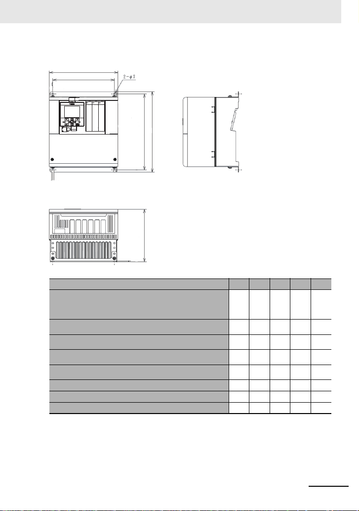
■外形寸法 (mm)
W
H1DH
W1
200V 級 :
3G3RX2-A2004,3G3RX2-A2007,3G3RX2-A2015,
3G3RX2-A2022,3G3RX2-A2037
400V 級 :
3G3RX2-A4007,3G3RX2-A4015,3G3RX2-A4022,
3G3RX2-A4037
200V 級 :
3G3RX2-A2055,3G3RX2-A2075,3G3RX2-A211
400V 級 :
3G3RX2-A4055,3G3RX2-A4075,3G3RX2-A4110
200V 級 :
3G3RX2-A2150,3G3RX2-A2185,3G3RX2-A2220
400V 級 :
3G3RX2-A4150,3G3RX2-A4185,3G3RX2-A4220
200V 級 :
3G3RX2-A2300
400V 級 :
3G3RX2-A4300
200V 級 :
3G3RX2-A2370,3G3RX2-A2450
400V 級 :
200V 級 : 3G3RX2-A2550 480 380 700 670 250
400V 級 : 3G3RX2-B4750,3G3RX2-B4900 390 300 700 670 270
400V 級 : 3G3RX2-B411K,3G3RX2-B413K 480 380 740 710 270
3G3RX2-A4370,3G3RX2-A4450,3G3RX2-A4550
形 3G3RX2- W W1 H H1 D
150 130 255 241 140
210 189 260 246 170
245 229 390 376 190
300 265 540 510 195
390 300 550 520 250
仕様
15
Page 16
仕様
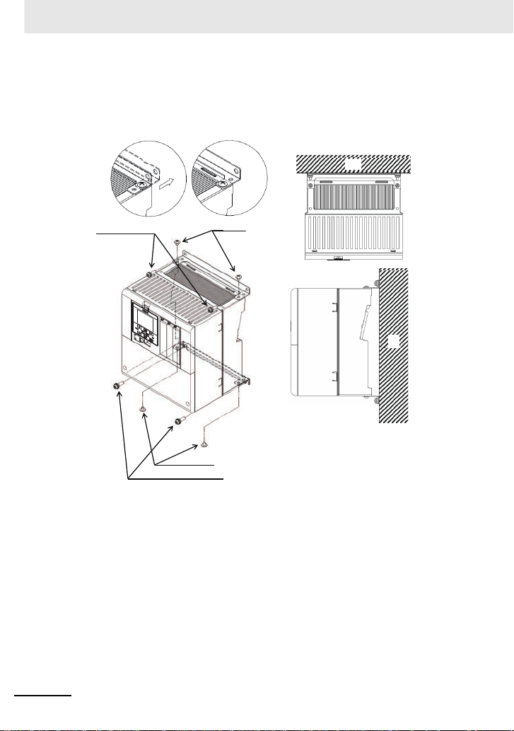
■取付上の注意
3G3RX2-A2110 において軽負荷定格 (LD)/ 超軽負荷定格 (VLD) にてご使用される場合、ならびに、
3G3RX2-A2220 において超軽負荷定格電流 (VLD) にてご使用される場合、以下の図の据付け方法に注
意して取り付ける必要があります。以下の手順で、お客様にて対応をお願いします。
手順①
お客様にて準備いただくネジ
手順④
お客様にて準備いただくネジ
図 据付け方法
ネジ
手順③
手順④
手順②
ネジ
手順③
壁
壁
図 平面・右側面図
※ 軽負荷定格 (LD)/ 超軽負荷定格 (VLD) への設定は [Ub-03]=00(VLD)、[Ub-03]=01(LD) と設定す
ることで変更します。
16
Page 17
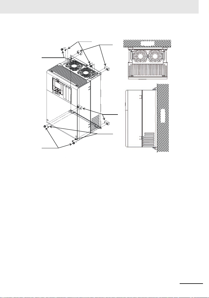
図 据付け方法
M3×8 ネジ 手順① 手順①
手順①
手順②
手順②
スペーサ
スペーサ
お客様にて
準備いただくネジ
お客様にて
準備いただくネジ
M3×8 ネジ
壁
壁
図 平面・右側面図
形 3G3RX2-A2220 の場合
※ 超軽負荷定格 (VLD) への設定は [Ub-03]=00 と設定することで変更します。
仕様
17
Page 18

設置条件
ねじ留め
ねじ留め
ねじ留め
ねじ留め
5cm以上5cm以上
30cm以上
30cm以上
5cm以上5cm以上
10cm以上
10cm以上 *1
*1 メンテナンス修理用スペースとして下部を 22cm 以上開けて据え付けてください。
・ 3G3RX2-A2150〜3G3RX2-A2220
・ 3G3RX2-A4150〜3G3RX2-A4220
下記の寿命部品交換には、インバータ本体を取り外す必要があります。
・ 3G3RX2-A2055〜3G3RX2-A2110
・ 3G3RX2-A4055〜3G3RX2-A4110
3G3RX2-A2004 〜 3G3RX2-A2550
3G3RX2-A4007 〜 3G3RX2-A4550
の場合
3G3RX2-B4750 〜 3G3RX2-B413K
の場合
設置条件
■機器周辺寸法条件
設置方法、設置方向にはご注意ください!
• インバータは、振動を受けない重量に耐えられる取り付け面に、ねじ、またはボルトで、がた
つきの無いようにしっかりと垂直に取り付けてください。
• 正しく取り付けない場合、冷却能力が低下し、トリップまたは破損の恐れがあります。
不燃性(金属など)の取り付け面に据付けてください!
• インバータは高温(最高 150 ℃程度)になります。火災の恐れがありますので、不燃性の垂直
な壁面(金属など)に据付けてください。また、本体重量を十分に支えられる構造になっている
ことを確認してください。
• 発熱体(制動抵抗器、リアクトル等)がある場合は、インバータと十分に離してください。
18
Page 19
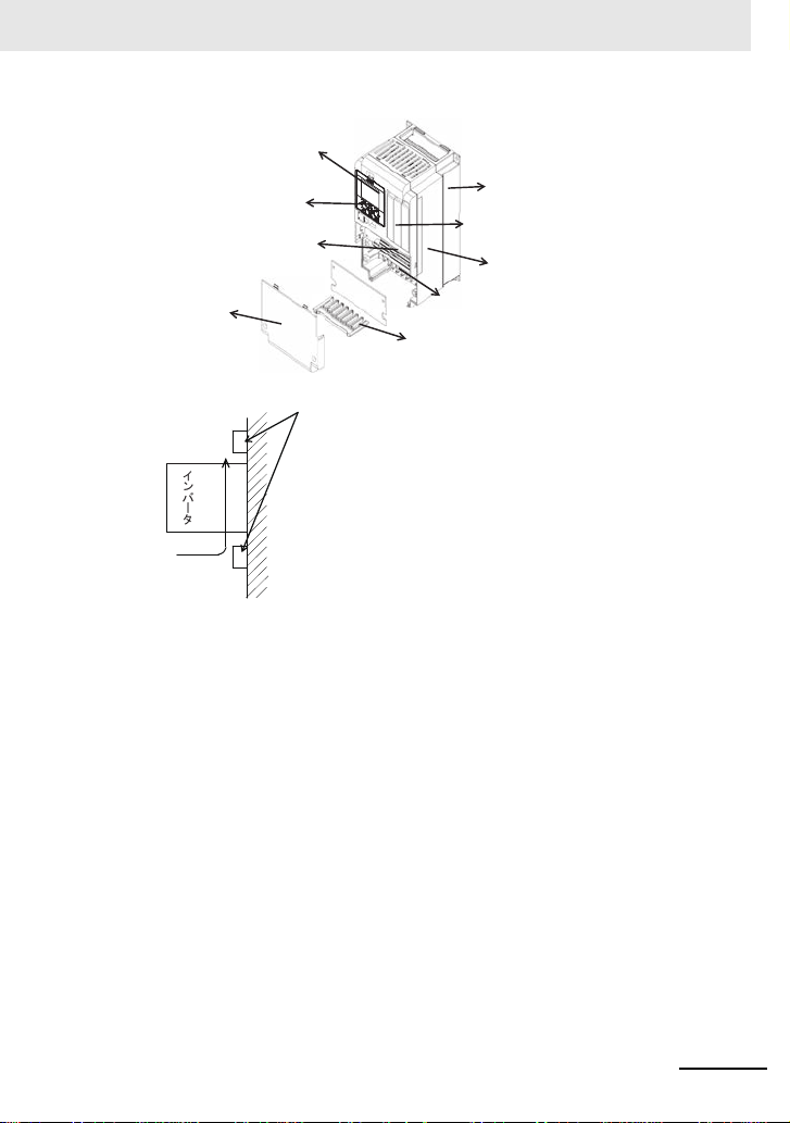
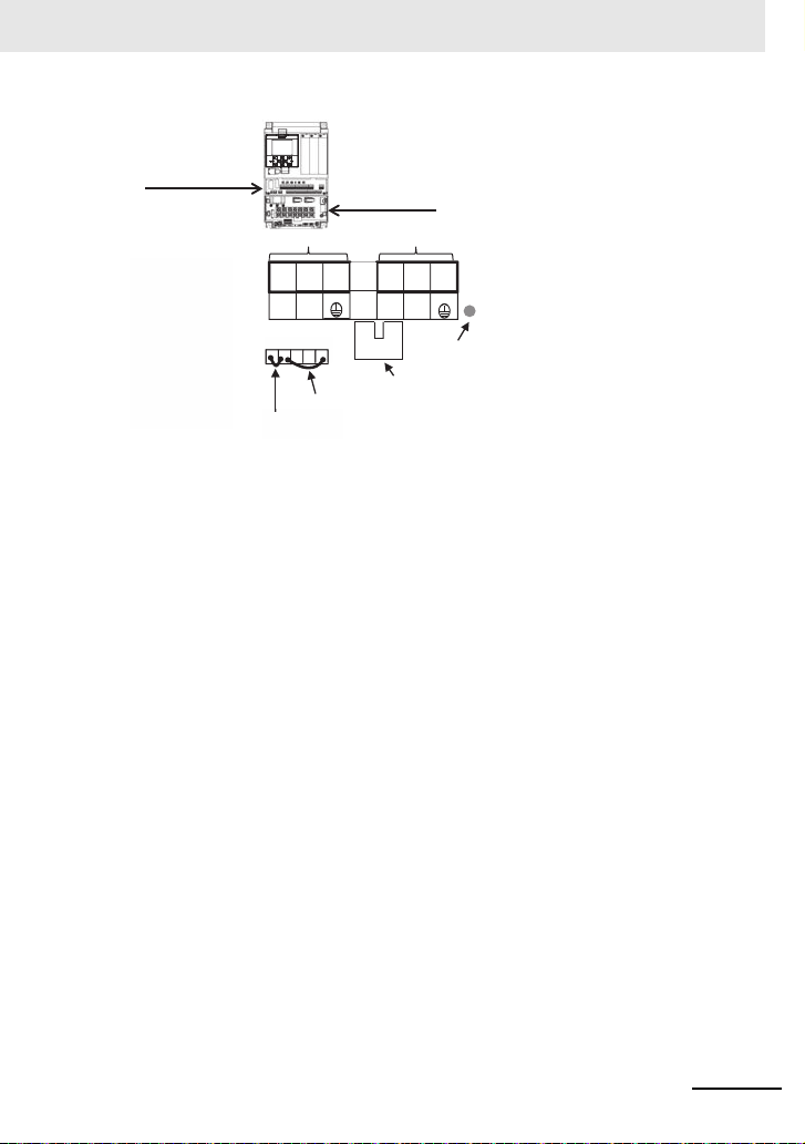
ᨺ⇕䝣䜱䞁
ᵝ㖭ᯈ
䜸䝥䝅䝵䞁䜹䝉䝑䝖᥋⥆㒊
㼁㻿㻮䠄 㻹㼕㼏㼞㼛㻙㻮
㻕
➃Ꮚྎ䜹䝞䞊
ไᚚᅇ㊰➃Ꮚྎ
㟁⥺ᘬฟᯈ
ᅇ㊰➃Ꮚྎ
㻸㻯㻰䜸䝨䝺䞊䝍
ቨ
䞉ୖୗ䛾㓄⥺䝎䜽䝖䛺䛹䛜䚸㻌෭༷
䛾㏻㢼䜢ጉ䛢䛺䛔ᵝ䛻༑ศ䛺
䝇䝨䞊䝇䜢☜ಖ䛧䛶䛟䛰䛥䛔䚹㻌
叻呉吧 呎吖
✵Ẽ䛾ὶ䜜
■使用環境条件
• 設置場所の湿度は、標準仕様に記載されている
湿度(20 〜 90%RH)で使用してください。特に、結露がない場所で使用してください。
• 結露が起き、インバータ内部に水滴が付着すると、電気回路が短絡し故障の原因になります。
また、直射日光の当たる場所への設置は避けてください。
設置条件
19
Page 20
主回路
㻱㻸㻮㻌㻖㻝
₃㟁㐽᩿ჾ 㟁☢᥋ゐჾ
㻹㻯
㻟┦
ὶ
㟁※
㻾㻛㻸㻝
㻿㻛㻸㻞
㼀㻛㻸㻟
㻾㻜
㼀㻜
㼁㻛㼀㻝
㼂㻛㼀㻞
㼃㻛㼀㻟
ไᚚᅇ㊰㟁※
㻰✀᥋ᆅ㻔㻞㻜㻜㼂 ⣭㻕
㻯✀᥋ᆅ㻔㻠㻜㻜㼂 ⣭㻕
㻶㻡㻝 䝁䝛䜽䝍
㻟 ┦ὶ䝰䞊䝍㻌㻖㻞
㻹
ᅇ㊰➃Ꮚ㒊
㻟䡚
▷⤡∦䜎䛯䛿➃Ꮚ
↓ຠ
᭷ຠ
㻼
㻼㻰
㻾㻮
㻺
▷⤡∦
ෆⶶ 㻱㻹㻯 䝣䜱䝹䝍㻌㻖㻟
㻞㻜㻜㼂⣭䠖
㻞㻜㻜䡚㻞㻠㻜㼂㼍㼏
㻠㻜㻜㼂⣭䠖
㻟㻤㻜䡚㻡㻜㻜㼂㼍㼏
主回路
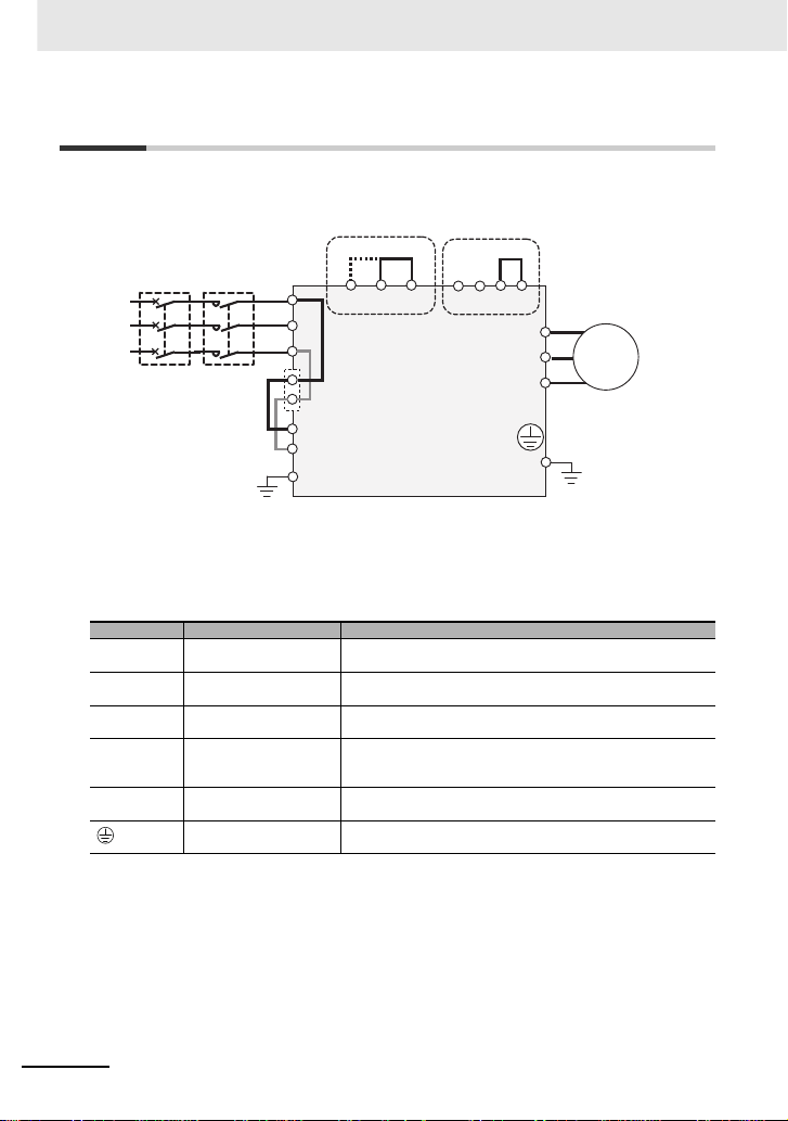
■主回路配線図
■主回路端子
R、S、T
(L1、L2、L3)
U、V、W
(T1、T2、T3)
PD、P
(+1、+)
P、RB
(+、RB)
P、N
(+、-)
20
*1. ELB の代わりにヒューズをいれてもよい。
*2. 規格に適合させる場合は後述の条件に合った機器・配線材を使用してください。
*3. 出荷時、EMC フィルタは有効に設定されています。規格適合が不要で ELB がトリップする場合には無効
に変更してください。
端子記号 端子名称 内容説明
主電源入力端子 交流電源に接続します。
インバータ出力端子 三相モータ を接続します。
直流リアクトル接続端子 端子 PD-P 間の短絡片を外し、オプションの力率改善用リアクトル
外部制動抵抗器接続端子 制動抵抗動作回路内蔵機種は、オプションの外 部制動抵抗器を接続
回生制動ユニット接続端子 オプションの回生制動ユニット BRD を接続します。
インバータ用接地端子 インバータケースの接地端子です。大地に接地してください。
DCL を接続します。
します。制動抵抗動作回路を搭載していない機種には、RB 端子は
ありません。
200V 級は D 種接地、400V 級は C 種接地に接続してください。
Page 21
主回路
㟁※ධຊ⥺
䝰䞊䝍 ฟຊ⥺
㻼㻰㻙㻼▷⤡∦
㻱㻹㻯
䝣 䜱 䝹䝍 ᭷ຠ
㻱㻹㻯
䝣 䜱 䝹䝍 ↓ຠ
ไᚚᅇ㊰➃Ꮚྎ
ᅇ㊰➃Ꮚྎ
㟁
㼀㻜 㻳
㻱㻹㻯
㻾㻮
㻔㻾㻮㻕
㻼㻰
㻔㻗 㻝㻕
㻼
㻔㻗 㻕㻺㻔㻙㻕
㻳
䝏䝱䞊䝆䝷䞁 䝥
㻔㏻㟁Ⅼⅉ㻕
㻾
㻔㻸㻝㻕㻿㻔㻸㻞㻕㼀㻔㻸㻟㻕㼁㻔㼀㻝㻕㼂㻔㼀㻞㻕㼃㻔㼀㻟㻕
㻾㻜
㻻㻲㻲㻌㻳㻌㻌㻌㻌㻌㻌㻻㻺
㻱㻹㻯
* EMC フィルタは短絡コネクタを入れ替えて有効 / 無効を切り替えます。
* 端子配列例です。
21
Page 22
主回路
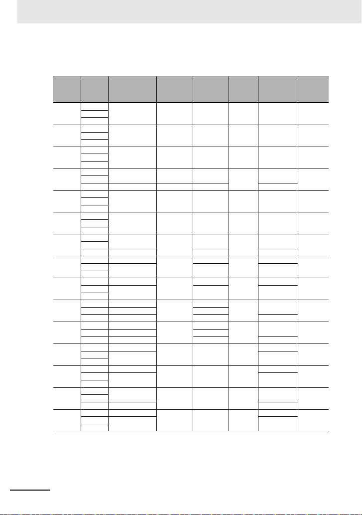
■主回路配線の端子配線径
200V 級
形式
定格設定
3G3RX2
A2004
A2007
A2015
A2022
A2037
A2055
A2075
A2110
A2150
A2185
A2220
A2300
A2370
A2450
A2550
(注)1. 上記表に記載の電線径は、HIV 線(耐熱 75 ℃)基準の設計値を示します。
ND
VLD
ND
VLD
ND
VLD
ND
VLD 10(5.3) 10(5.3) 10(5.3) 5.5-4/5.5-4
ND
VLD
ND
VLD
ND
VLD 6(13.3) 6(13.3) 14-5/8-5
ND 6(13.3)
VLD
ND 4(21.2)
VLD
ND 3(26.7)
VLD 1(42.4) 1(42.4) 60-6/14-6
ND 1(42.4)
VLD 2/0(67.4) 2/0(67.4) 70-8/14-6
ND 2/0(67.4)
VLD
ND 4/0(107.2)
VLD
ND
VLD 2/0×2(67.4×2) 70- 8/22-8
ND 350kc(177)
VLD
2. 主回路端子台に電線を接続する場合は、使用電線に合った丸型 圧着端子(UL 規格対応品)を使用 してください。圧
着端子は圧着端子メーカの推奨する圧着工具を使用し圧着してください。
動力線
2
接地線
)
AWG(mm
R、S、T、U、V、
W、P、PD、N
14(2.1) 14(2.1) 14(2.1) M4 2-4/2-4 1.4LD
14(2.1) 14(2.1) 14(2.1) M4 2-4/2-4 1.4LD
14(2.1) 14(2.1) 14(2.1) M4 2-4/2-4 1.4LD
14(2.1) 14(2.1) 14(2.1)
10(5.3) 10(5.3) 10(5.3) M4 5.5-4/5.5-4 1.4LD
8(8.4) 8(8.4) 8(8.4) M5 8-5/8-5 3.0LD
8(8.4)
4(21.2) 4(21.2) 22-6/14-6
3(26.7) 3(26.7) 38-6/14-6
1/0×2(53.5×2) 60-8/22-8
1/0×2(53.5×2) 60-8/22-8
1/0×2(53.5×2)
3/0×2(85.0×2) 80-10/38-8
AWG(mm
6(13.3)
6(13.3)
6(13.3)
6(13.3)
6(13.3)
4(21.2) - M8
4(21.2) - M8
4(
21.2) - M
3(26.7) - M10
2
)
制動抵抗器
P-RB 間
AWG(mm
8(8.4)
6(13.3)
4(21.2)
3(26.7)
1(42.4)
動力線
端子ネジ
2
サイズ
)
M4
M5
M6
M6
M6
M8
8
圧着端子
動力線 / 接地線
2-4/2-4
8-5/8-5
14-6/14-6
22-6/14-6
38-6/14-6
60-8/14-6
70-8/22-8
100-8/22-8
60-8/22-8
180-10/38-8
締付トルク
N・m
1.4LD
3.0LD
4.0LD
2.5 〜 3.0LD
2.5 〜 3.0LD 2(33.6) 2(33.6)
5.5 〜 6.6LD 1/0(53.5) 1/0(53.5)
6.0LD
15.0LD
6.0 〜 10.0LD
19.6LD
22
Page 23
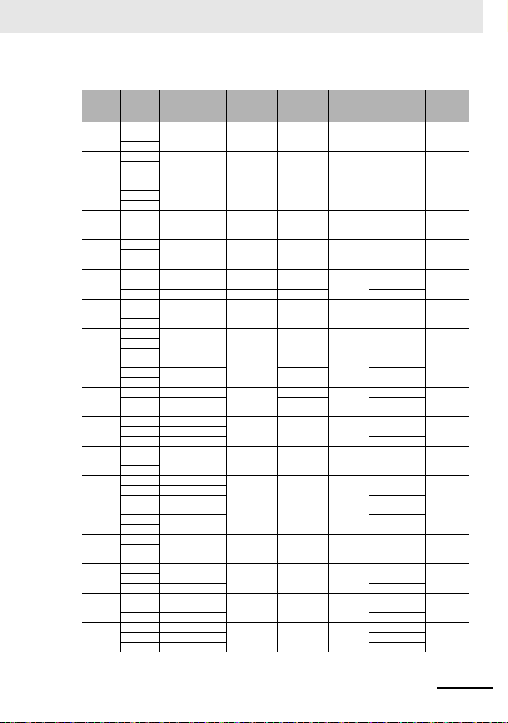
400V 級
形式
3G3RX2定格設定
A4007
A4015
A4022
A4037
A4055
A4075
A4110
A4150
A4185
A4220
A4300
A4370
A4450
A4550
B4750
B
B411K
B413K
(注)1. 上記表に記載の電線径は、HIV 線(耐熱 75°C)基準の設計値を示します 。
ND
VLD
ND
VLD
ND
VLD
ND
VLD 12(3.3) 12(3.3 ) 12(3.3) 5.5-4/5.5-4
ND
VLD 10(5.3) 10(5.3 ) 10(5.3)
ND
VLD 8(8.4) 8(8.4) 8(8.4) 8-5/8-5
ND
VLD
ND
VLD
ND 8(8.4)
VLD
ND 6(13.3)
VLD
ND 3(26.7)
VLD 1(42.4) 60-8/14-8
ND
VLD
ND 1(42.4)
VLD 2/0(67.4) 70-8/14-8
ND 2/0(67.4)
VLD
ND
VLD
ND
4900
VLD 2/0×2(67.4×2) 70-10/38-8
ND
VLD 3/0×2(85.0×2) 80-10/38-8
ND 3/0×2(85.0×2)
VLD
2. 主回路端子台に電線を接続する場合は、使用電線に合った 丸型圧着端子(UL 規格対応品 )を使用してください。
圧着端子は圧着端子メーカの推奨する圧着工具を使用し圧着してください。
動力線
2
接地線
)
AWG(mm
R、S、T、U、V、
W、P、PD、N
AWG(mm
14(2.1) 14(2.1) 14(2.1) M4 2-4/2-4 1.4LD
14(2.1) 14(2.1) 14(2.1) M4 2-4/2-4 1.4LD
14(2.1) 14(2.1) 14(2.1) M4 2-4/2-4 1.4LD
14(2.1) 14(2.1) 14(2.1)
12(3.3) 12(3.3) 12(3.3)
10(5.3) 10(5.3) 10(5.3)
8(8.4) 8(8.4) 8(8.4) M6 8-6/8-6 4.0LD
8(8.4) 8(8.4) 8(8.4) M6 8-6/8-6 4.0LD
6(13.3) 6(13.3) 14-6/8-6
4(21.2) 4(21.2) 22-6/8-6
8(8.4)
8(8.4)
6(13.3) - M8
1(42.4) 6(13.3) - M8 60-8/14-8 15.0LD
6(13.3) - M8
1/0×2(53.5×2) 60-8/22-8
4(21.2) - M8
1/0×2(53.5×2) 4 (21.2) - M10 60-10/22-8 6.0 〜 10.0LD
(53.5×2)
1/0×2
2/0×2(67.4×2)
250kc×2(127×2)
3(26.7) - M10
2(33.6) - M10
2(33.6) - M10
2
)
制動抵抗器
P-RB 間
AWG(mm
8(8.4)
6(13.3)
主回路
動力線
端子ネジ
2
サイズ
)
M4
圧着端子
動力線 / 接地線
2-4/2-4
M5 5.5-5/5.5-5 3.0LD
5.5-5/5.5-5
M5
8-6/8-6
M6
14-6/8-6
M6
38-8/14-8
60-8/14-8
70-8/22-8
60-10/38-8
70-10/38-8
80-10/38-8
150-10/38-8
6.0 〜 10.0LD 1/0(53.5)
6.0 〜 10.0LD
6.0 〜 10.0LD
締付
トルク
N・m
1.4LD
3.0LD
4.0LD
4.0LD
6.0LD 2(33.6)
19.6LD
19.6LD 4/0×2(1 07×2) 100-10/38-8
23
Page 24
主回路
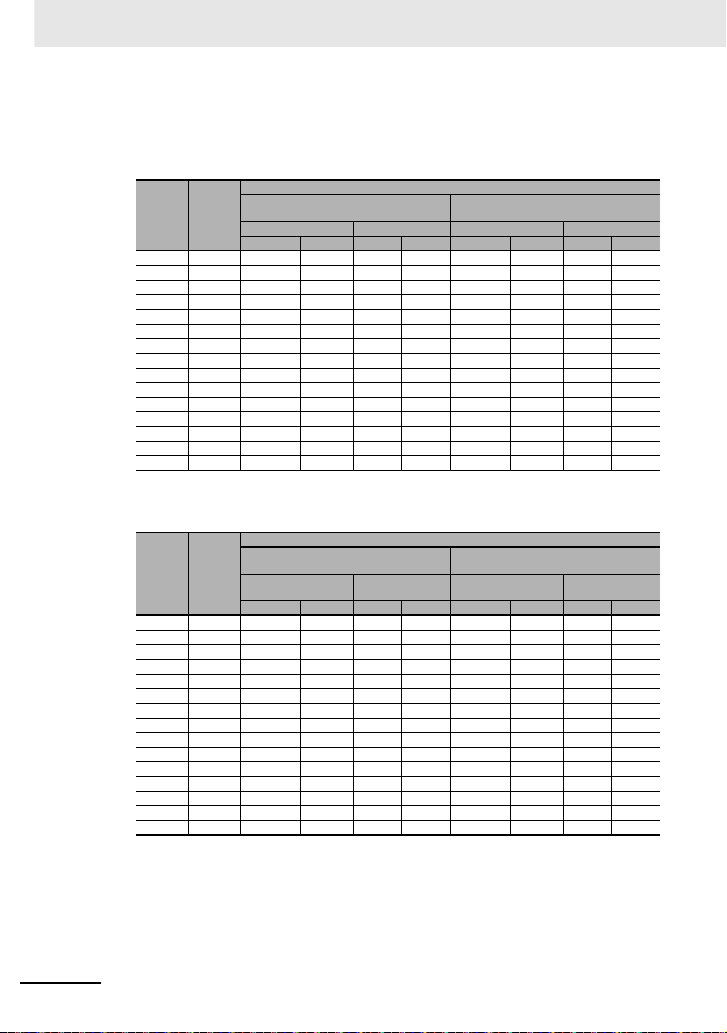
■適用ブレーカ
200V 級
• インバータ ND 定格設定時
適用
形式
モータ
3G3RX2
(kW)
A2004 0.4 EB-30E 5 HS8 HS8 EB-30E 5 HS8 HS8
A2007 0.75 EB-30E 10 HS8 HS8 EB-30E 5 HS8 HS8
A2015 1.5 EB-30E 15 HS8 HS8 EB-30E 10 HS8 HS8
A2022 2.2 EB-30E 20 HS8 HS8 EB-30E 15 HS8 HS8
A2037 3.7 EB-30E 30 HS8 HS20 EB-30E 20 HS8 HS20
A2055 5.5 EB-50E 40 HS20 HS25 EB-30E 30 HS8 HS20
A2075 7.5 EB-50E 50 HS35 HS35 EB-50E 40 HS20 HS25
A2110 11 EB-100E 75 HS50 H65C EB-100E 60 HS35 HS50
A2150 15 RXK125-S 125 H65C H80C EB-100E 100 HS50 H65C
A2185 18.5 RXK125-S 125 H80C H100C EB-100E 100 HS50 H65C
A2220 22 EXK225 150 H80C H125C RXK125-S 125 H65C H80C
A2300 30 EXK225 200 H125C H150C EXK225 150 H80C H125C
A2370 37 RXK250-S 250 H150C H200C EXK225 200 H100C H125C
A2450 45 EX400 300 H200C H250C EXK225 225 H125C H150C
A2550 55 EX400 400 H200C H300C EX400 300 H150C H250C
力率改善リアクトルなし
漏電遮断器(ELB) 電磁接触器(MC) 漏電遮断器(ELB) 電磁接触器(MC)
形式例 定格電流 AC-1 AC-3 形式例 定格電流 AC-1 AC-3
適用器具(入力電圧 200 〜 220V )
力率改善リアクトル
(形 3G3AX-AL または形 3G3AX-DL)あり
• インバータ LD/VLD 定格設定時
適用器具(入力電圧 200 〜 220V )
適用
形式
モータ
3G3RX2
(kW)
A2004 0.75 EB-30E 10 HS8 HS8 EB-30E 5 HS8 HS8
A2007 1.5 EB-30E 15 HS8 HS8 EB-30E 10 HS8 HS8
A2015 2.2 EB-30E 20 HS8 HS8 EB-30E 15 HS8 HS8
A2022 3.7 EB-30E 30 HS8 HS20 EB-30E 20 HS8 HS20
A2037 5.5 EB-50E 40 HS20 HS25 EB-30E 30 HS8 HS20
A2055 7.5 EB-50E 50 HS35 HS35 EB-50E 40 HS20 HS25
A2075 11 EB-100E 75 HS50 H65C EB-100E 60 HS35 HS50
A2110 15 RXK125-S 125 H65C H80C EB-100E 100 HS50 H65C
A2150 18.5 RXK125-S 125 H80C H100C EB-100E 100 HS50 H65C
A2185 22 EXK225 150 H80C H125C RXK125-S 125 H65C H80C
A2220 30 EXK225 200 H125C H150C EXK225 150 H80C H125C
A2300 37 RXK250-S 250 H150C H200C EXK225 200 H100C H125C
A2370 45 EX400 300 H200C H250C EXK225 225 H125C H150C
A2450 55 EX400 400 H200C H300C EX400 300 H150C H250C
A2550 75 EX600B 500 H300C H400C EX400 400 H200C H300C
(注)1.表に記載した形式は選定例です。ご使用の際は、表の定格 電流を元に、電源回路の短絡電流や関連法規などを考
慮の上、適切な遮断容量、感度電流を持つ機種を選定ください。
2. 適用モータ容量は、標準モータ 4 極の 60Hz200Vac(200V 級)を使用する場合の選 定例です。
3. 電磁接触器を AC-1 級でご使用の場合の電気的耐久性は、50 万回ですが、モータ駆動中の緊急停止は 25 回と
なります。
4. モータ駆動中の緊急停止あるいは商用運転がある場合のモータ側の 電磁接触器は、モータの定格電流に対して
AC-3 級で選定してくださ い。
5. インバータの定格容量がモータ容量よりも大きい場合は、インバー タ形式を元に選定してください。
力率改善リアクトルなし
漏電遮断器(ELB) 電磁接触器(MC) 漏電遮断器(ELB)
形式例 定格電流 AC-1 AC-3 形式例 定格電流 AC-1 AC-3
力率改善リアクトル
(形 3G3AX-AL または形 3G3AX-DL)あり
電磁接触器
(MC)
24
Page 25
400V 級
• インバータ ND 定格設定時
適用
形式
モータ
3G3RX2
(kW)
A4007 0.75 EX50C 5 HS8 HS8 EX50C 5 HS8 HS8
A4015 1.5 EX50C 10 HS8 HS8 EX50C 5 HS8 HS8
A4022 2.2 EX50C 10 HS8 HS8 EX50C 10 HS8 HS8
A4037 3.7 EXK50-C 15 HS8 HS10 EX50C 10 HS8 HS8
A4055 5.5 EXK50-C 20 HS8 HS20 EXK50-C 15 HS8 HS20
A4075 7.5 EXK50-C 30 HS8 HS25 EXK50-C 20 HS8 HS20
A4110 11 EXK50-C 40 HS20 HS35 EXK50-C 30 HS8 HS25
A4150 15 EXK50-C 50 HS25 HS50 EXK50-C 40 HS20 HS35
A4185 18.5 EXK100-C 75 HS35 HS50 EXK 50-C 50 HS20 HS35
A4220 22 EXK100-C 75 HS50 H65C EXK60-C 60 HS35 HS50
A4300 30 EXK100-C 100 HS50 H80C EXK100-C 75 HS50 H65C
A4370 37 RXK125-S 125 H80C H 100C EXK100-C 100 HS50 H65C
A4450 45 EX K225 150 H80C H125C RXK125-S 125 H65C H80C
A4550 55 EX K225 200 H100C H125C EXK225 150 H80C H100C
B4750 75 RXK250-S 250 H150C H200C EXK225 200 H100C H125C
B4900 90 EX400 300 H200C H250C EXK225 225 H125C H150C
B411K 110 EX400 400 H200C H300C EX400 300 H15 0C H250C
B413K 132 EX600B 500 H250C H300C EX400 350 H200C H250C
力率改善リアクトルなし
漏電遮断器(ELB) 電磁接触器(MC) 漏電遮断器(ELB) 電磁接触器(MC)
形式例 定格電流 AC-1 AC-3 形式例 定格電流 AC-1 AC-3
適用器具(入力電圧 400 〜 44 0V)
力率改善リアクトル
(形 3G3AX-A L または形 3G3AX-DL)
主回路
あり
• インバータ LD/VLD 定格設定時
適用
形式
モータ
3G3RX2
(kW)
A4007 1.5 EX50C 10 HS8 HS8 EX50C 5 HS8 HS8
A4015 2.2 EX50C 10 HS8 HS8 EX50C 10 HS8 HS8
A4022 3.7 EXK50-C 15 HS8 HS10 EX50C 10 HS8 HS8
A4037 5.5 EXK50-C 20 HS8 HS20 EXK50-C 15 HS8 HS20
A4055 7.5 EXK50-C 30 HS8 HS25 EXK50-C 20 HS8 HS20
A4075 11 EXK50-C 40 HS20 HS35 EXK50-C 30 HS8 HS25
A4110 15 EXK50-C 50 HS25 HS50 EXK50-C 40 HS20 HS35
A4150 18.5 EXK100-C 75 HS35 HS50 EXK 50-C 50 HS20 HS35
A4185 22 EXK100-C 75 HS50 H65C EXK60-C 60 HS35 HS50
A4220 30 EXK100-C 100 HS50 H80C EXK100-C 75 HS50 H65C
A4300 37 RXK125-S 125 H80C H 100C EXK100-C 100 HS50 H65C
A4370 45 EX K225 150 H80C H125C RXK125-S 125 H65C H80C
A4450 55 EX K225 200 H100C H125C EXK225 150 H80C H100C
A4550 75 EX400 250 H150C H200C EXK225 200 H100C H125C
B4750 90 EX400 300 H200C H250C EXK225 225 H125C H150C
B4900 110 EX400 400 H200C H300C EX400 300 H 150C H250C
B411K 132 EX600B 500 H250C H300C EX400 350 H200C H250C
B413K 160 EX600B 600 H400C H400C EX400 400 H250C H300C
(注)1.表に記載した形式は選定例です。ご使用の際は、表の定格電流を元 に、電源回路の短絡電流や関連法規などを考
慮の上、適切な遮断容量、感度電流を持つ機種を選定ください。
2. 適用モータ容量は、標準モータ 4 極の 60Hz400Vac(400V 級)を使用する 場合の選定例です。
3. 電磁接触器を AC-1 級でご使用の場合の電気的耐久性は、50 万回ですが、モータ駆動中の緊急停止は 25 回と
なります。
4. モータ駆動中の緊急停止あるいは商用運転がある場合の モータ側の電磁接触器は、モータの定格電流に対して
AC-3 級で選定してく ださい。
5. インバータの定格容量がモータ容量よりも大きい場合は 、インバータ形式を元に選定してください。
力率改善リアクトルなし
漏電遮断器(ELB) 電磁接触器(MC) 漏電遮断器(ELB) 電磁接触器(MC)
形式例 定格電流 AC-1 AC-3 形式例 定格電流 AC-1 AC-3
適用器具(入力電圧 400 〜 44 0V)
力率改善リアクトル
(形 3G3AX-AL または形 3G3AX-D L)あり
25
Page 26
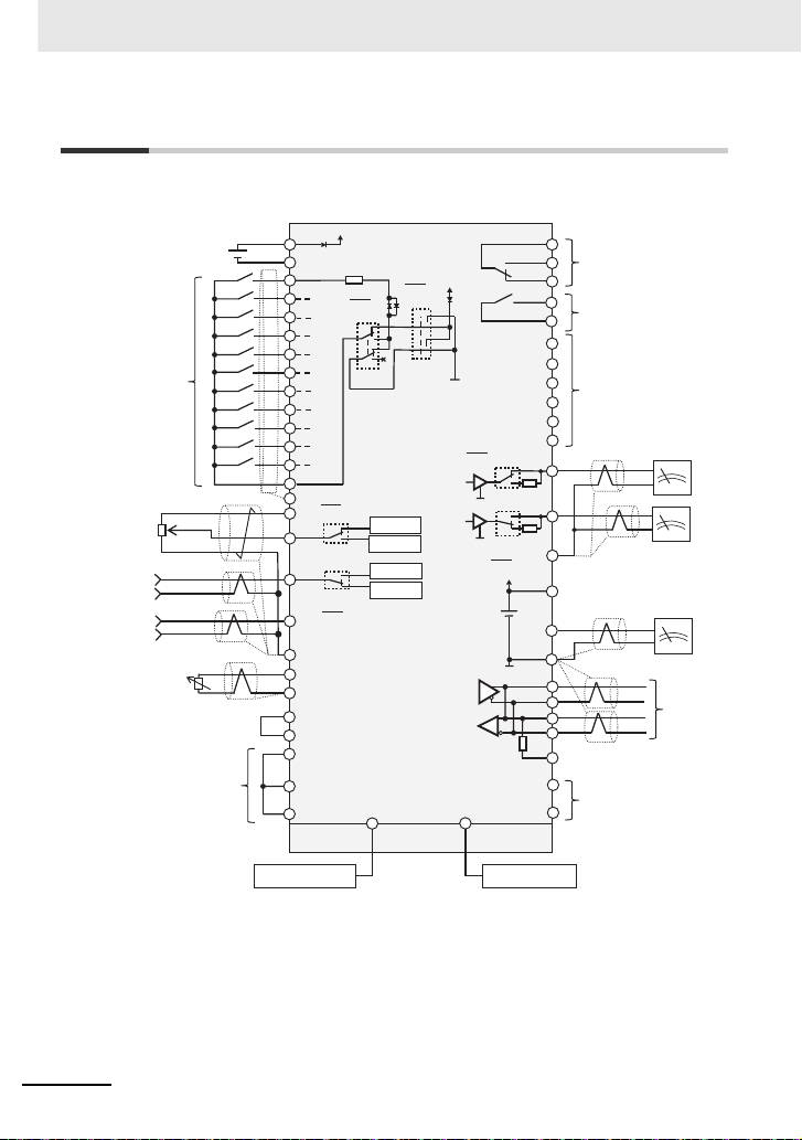
制御回路
ไᚚᅇ㊰➃Ꮚ㒊
䝞䝑䜽䜰䝑䝥⏝
㻞㻠㼂⤥㟁⏝➃Ꮚ
㻼㻗
㻼㻙
㻝㻛㻾㻿
㻞㻛㻿㻯㻴㻳
㻟㻛㻶㻳
㻠㻛㻲㻾㻿
㻡㻛㻞㻯㻴
㻢㻛㻯㻲㻝
㻣㻛㻯㻲㻞
㻤㻛㻾㼂
㻥㻛㻲㼃
㻭㻛㻱㼄㼀
㻮㻛㼁㻿㻼
㻯㻻㻹
㻯㻹㻝
䜲䞁䝍䞊䝣䜵䞊䝇
㻞㻠㼂㟁※➃Ꮚ
㻼㻞㻠
㻴
㻭㼕㻝
㻭㼕㻞
㻭㼕㻟
㻸
䜰䝘䝻䜾
ධຊ 㻝
㻔㻗㻕
㻔㻙㻕
㻔㼼 㻝㻜㼂㻕
㻔㻜 㼂㻕
㼀㻴㻗
㻭㻸㻞
㻭㻸㻝
㻭㻸㻜
㻝㻢㻭
㻝㻢㻯
㻝㻝㻛㻾㼁㻺
㻝㻞㻛㻲㻭㻝
㻝㻟㻛㻲㻭㻞
㻝㻠㻛㻵㻾㻰㼅
㻝㻡㻛㻻㻸
㻯㻹㻞
㻲㻹
㻯㻹㻝
㻭㼛㻝
㻭㼛㻞
㻸
㻿㻼
㻿㻺
㻿㻼
㻿㻺
㻾㻼
㻼㻞㻠㻿
㻿㼀㻯
㻯㻹㻿
㻿㼀㻝
㻿㼀㻞
㻱㻰㻗
㻱㻰㻙
㼀㻴㻙
䜰䝷䞊䝮䝸䝺䞊
㻝㻯᥋Ⅼ
䝸䝺䞊
㻝㻭᥋Ⅼ
ฟຊ➃Ꮚ
䈜䝅䞁䜽 㻛䝋䞊䝇ᑐᛂ
㻸
㻸
㻝㻜㼂
㻝㻜㼂
㻞㻜㼙㻭
㻝㻜㼂
㻝㻜㼂
㻞㻜㼙㻭
㻞㻜㼙㻭
ධຊ➃Ꮚ
䝃䞊䝭䝇䝍
㻾㻿㻠㻤㻡➃Ꮚ
㻹㼛㼐㼎㼡㼟㏻ಙ
㻿㼀㻻ධຊ
㻿㼀㻻☜ㄆฟຊ
䜰䝘䝻䜾
ධຊ 㻞
䜰䝘䝻䜾
ධຊ 㻟
ධຊ➃Ꮚ䛾䝅䞁䜽䞉
䝋䞊䝇ㄽ⌮䛾ษ᭰䛿䚸
㻿㼃㻢䛷ษ䜚᭰䛘䜎䛩䚹
㻼㻞㻠
㻯㻹㻝
㻰㻯㻞㻠㼂
㻼㻞㻠
㻯㻹㻝
㻼㻞㻠
㻵㻺
㻱㼄
䝋䞊䝇
䝅䞁䜽
㻔㻿㼃㻡㻕
㻔㻿㼃㻢㻕
㻔㻿㼃㻝㻕
㻔㻿㼃
㻞㻕
㻔㻿㼃㻟㻕
㻔㻿㼃㻠㻕
㻝㻢㻛㼆㻿
᧯స㒊
㼁㻿㻮
㻾㻶㻠㻡
㻼㻯㻔㻼㼞㼛㻰㼞㼕㼢㼑㻺㼑㼤㼠㻕
㻸㻯㻰䜸䝨䝺䞊䝍
䈜㻾㻿㻠㻤㻡➃Ꮚ䛾䝅䜾䝘䝹
䜾䝷䜴䞁䝗䛿㻯㻹㻝䛷䛩䚹
㻞㻜㼙㻭
㟁ᅽධຊ
㟁ὶධຊ
㟁ᅽධຊ
㟁ὶධຊ
制御回路
26
■制御回路への配線
Page 27
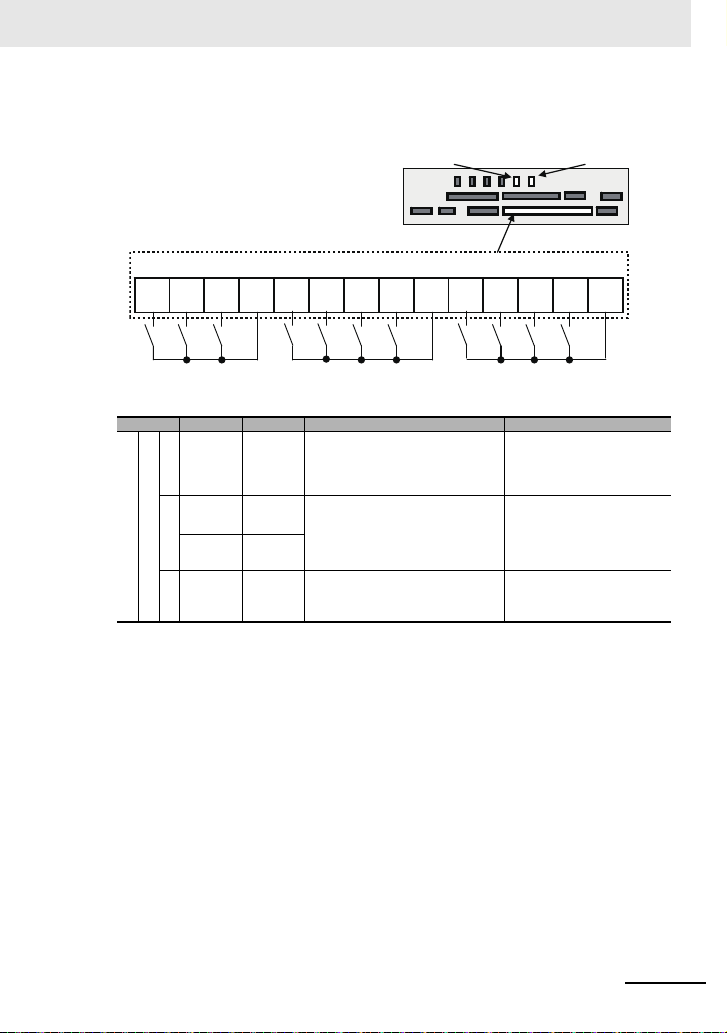
■入力端子
ධຊ➃Ꮚ㻌
㻝
㻌
㼇㻾㻿㼉 㻌
㻞
㻌
㼇㻿㻯㻴㻳㼉
㻌
㻟
㻌
㼇㻶㻳㼉㻌
㻠
㻌
㼇㻲㻾㻿㼉 㻌
㻡
㻌
㼇㻞㻯㻴㼉 㻌
㻢
㻌
㼇㻯㻲㻝㼉 㻌
㻣
㻌
㼇㻯㻲㻞㼉 㻌
㻤
㻌
㼇㻾㼂㼉 㻌
㻥
㻌
㼇㻲㼃㼉 㻌
㻭
㻌
㼇㻱㼄㼀㼉 㻌
㻮
㻌
㼇㼁㻿㻼 㼉㻌
㻯㻻㻹 㻌㻯㻻㻹 㻌㻯㻻㻹 㻌
ไᚚᅇ㊰➃Ꮚ㒊㻌
㻿㼃㻢 㻌
㻿㼃㻡 㻌
• COM はすべて同じ電位です。
• 1 〜 9、A、B と COM の間に電源を接
続する場合は、SW5 を外部電源 (EX) に
切り替えます。
• 入力端子のシンク / ソースは SW6 で切
り替えます。
( 配線例)
• 端子機能名は工場出荷初期設定で記載しています。
イ
ン
テ
リ
ジ
ェ
ン
ト
入
力
端
子
端子記号 端子名称 内容説明 電気的特性
9、8、7、
6、5、4、
接
3、2、1
点
デ
A パルス
ジ
パ
タ
ル
ル
B パルス
ス
入
力
COM 入力端子用
コ
モ
ン
入力端子 各端子 に対応したパラメータ設定によって
入力 -A
入力 -B
コモン
端子機能が選択できます。
シンク論理、ソース論理の切り替えは、
SW6 の SRC/SINK を切り替えること で可
能です。
パルス入力用の端子です。A、B 端子は、
入力端子としても使用できます。
各端子に対応したパラメータ設定によって
端子機能が選択できます。
最大入力パルスは 32kpp s です。
デジタル入力端子
(1、2、3、4、5、6、7、8、9、A、B)の
コモン端子です。COM 端子は 3 つありま
す。
制御回路
各入力 /COM 間電圧
• ON 電圧Min.DC18V
• OFF 電圧Max.DC3V
• 最大許容電圧 DC27V
• 負荷電流 5.6mA(DC27V 時)
各入力 /COM 間電圧
• ON 電圧Min.DC18V
• OFF 電圧Max.DC3V
• 最大許容電圧 DC27V
• 負荷電流 5.6mA(DC27V 時)
• 最大 32kpps パルス入力
27
Page 28

制御回路
正転 FW 逆転 RV 内容
OFF OFF 指令はありません。
ON OFF 正転指令動作
OFF ON 逆転指令動作
ON ON 指令はありません(論理不整合)
* CF3,4 を使用すると最大 15 速まで設定できます。
多段速 1
CF1
多段速 2
CF2
内容
OFF OFF 設定している周波数指令が有効
ON OFF [Ab-11]の周波数指令が 有効
OFF ON [Ab-12]の周波数指令が有効
ON ON [Ab-13]の周波数指令が有効
■入力端子機能([端子記号 : 設定番号])
ここでは出荷初期値の機能について説明します。詳細機能はユーザーズマニュアル (SBCE-437) で確認
してください。
[RS:028]リセット
• トリップした際にリセットします。
[SCHG:015]指令先切替
• 主速指令[AA101](OFF)と補助速指令
[AA102](ON)を切り替えます。
[JG:029]ジョギング
• [JG]ON で運転指令が入ると、[AG-20]の周
波数で動作します。
[FRS:032]フリーランストップ
• [FRS]ON でモータがフリーランします。
[2CH:031]二段加減速
• [2CH]ON で加減速時間 2[AC124]
[AC126]が有効になります。
[EXT:033]外部トリップ
• [EXT]ON でトリップ[E012]を発行します。
[FW:001]正転と[RV:002]逆転
[CF1:003]多段速 1 と[CF2:004]多段速 2 指令
[USP:034]復電再始動防止
• [USP]ON の状態で、電源投入時、運転指令が
入っているとトリップ[E013]を発行します。
28
Page 29

■出力端子
㻝㻢㻭 㻝㻢㻯
䝸䝺䞊
ฟຊ➃Ꮚ
㼄
㻭㻸㻞 㻭㻸㻝 㻭㻸㻜
䜰䝷䞊䝮䝸䝺䞊
ฟຊ➃Ꮚ
㼄
ไᚚᅇ㊰➃Ꮚ㒊
㻝㻝㻝㻞
㼇㻲㻭㻝㼉
㻝㻟
㼇㻲㻭㻞㼉
㻝㻠㻝㻡
㼇㻻㻸 㼉
㻯㻹㻞
ฟຊ➃Ꮚ
㻾㼅 㻾㼅 㻾㼅
㻾㼅 㻾㼅
㻔 㓄⥺㻕
㼇㻭㻸㼉 㼇㼆㻿㼉
㼄
㻦 䝷䞁䝥䚸䝸䝺䞊䚸㻼㻸㻯䛺䛹䛾⨨
㻦䝸䝺䞊
㼇㻵㻾㻰㼅㼉 㼇㻾㼁㻺㼉
㻾㼅
オープンコレクタ
リレー
• 端子機能名は工場出荷初期設定で記載しています。
イ
ン
テ
リ
ジ
ェ
ン
ト
出
力
端
子
端子記号 端子名称 内容説明 電気的特性
15
14
13
12
11
CM2 出力端子用
16A
16C
デ
ジ
タ
ル
AL0
出
AL1
力
AL2
出力端子 各端子 に対応したパラメータ設定によって
コモン
1a リレー端子A 接点出力のリレーで す。 接点最大容量
1c リレー端子C 接点出力のリレーで す。 接点最大容量
端子機能が選択できます。
シンク論理、ソース論理のいずれでも使用
可能です。
11 〜 15 の出力端子用のコモン端子
です。
制御回路
オープンコレクタ出力
• 各端子 /CM2 間
• ON 時電圧降下 4V 以下
• 最大許容電圧 27V
• 最大許容電流 50mA
• AC250V、2A(抵抗)
• AC250V、1A(誘導)
接点最小容量
• DC1V、1mA
AL1/AL0:
• AC250V、2A(抵抗)
• AC250V、0.2A(誘導)
AL2/AL0:
• AC250V、1A(抵抗)
• AC250V、0.2A(誘導)
接点最小容量(共通)
• AC100V、10mA
• DC5V、100mA
29
Page 30

制御回路
電源 状態 AL0 -AL1 AL0-AL2
ON 正常 開 閉
ON トリップ 閉 開
OFF−開閉
電源 状態 AL0 -AL1 AL0-AL2
ON 正常 閉 開
ON トリップ 開 閉
OFF−開閉
■出力端子機能
ここでは出荷初期値の機能について説明します。詳細機能はユーザーズマニュアル (SBCE-437) で確認
してください。
[RUN:001]運転中信号
• 運転(PWM 出力)中、ON します。
[FA1:002]周波数到達信号
• 出力周波数が指令周波数に到達すると ON しま
す。
[FA2:003]周波数到達信号 2
• 出力周波数が設定した周波数[CE-10]〜
[CE-13]に到達すると ON します。
[IRDY:007]運転準備完了
• 運転可能状態となった時に ON します。
[OL:035]過負荷予告
• 電流が過負荷予告レベルを超えると ON します。
[ZS:040]零速検出信号
• 出力周波数が 0Hz 検出レベル[CE-33]を下回
ると ON します。
[AL:017]動作について
• [CC-17]=00 の場合
• [CC-17]=01 の場合
30
Page 31

■アナログ入出力端子
㻭㼛㻞 㻭㼛㻝
䜰䝘䝻䜾ධฟຊ
㻴㻭㼕㻝㻭㼕㻞㻭㼕㻟㻸㻸
࿘Ἴᩘᣦ௧⏝ྍኚᢠჾ
㻔㻜㻚㻡㼗䃈䡚㻞㼗䃈㻕
䈜㻝㼗䃈䚸㻝㼃௨ୖ᥎ዡ
ไᚚᅇ㊰➃Ꮚ㒊
㻿㼃㻟㻿㼃㻠 㻿㼃㻞 㻿㼃㻝
࿘Ἴᩘィ
• 左の例は、可変抵抗器を H-Ai1-L 間に配
線する場合で電圧入力になりますので、
アナログ入力 1(Ai1)の SW1 を電圧側
に設定します。
• 左の例は、周波数計が電流対応型(4 〜
20mA)の場合、アナログ出力 1(Ao1)
の SW3 を電流側に設定します。
( 配線例 )
制御回路
端子記号 端 子名称 内容説明 電気的特性
電
源
電
圧
電
流
切
り
Ai1
替
ア
え
ナ
可
ロ
能
Ai2
グ
ア
入
ナ
力
ロ
グ
Ai3
入
出
力
ア
Ao1
端
ナ
子
ロ
グ
出
Ao2
力
アナログ
電源コモン
L
速度設定用電源DC10V 電源です。アナログ入力端子
H
アナログ
入力端子 1
(電圧 / 電流
切替 SW1)
アナログ
入力端子 2
(電圧 / 電流
切替 SW2)
アナログ
入力端子 3
アナログ
出力端子 1
(電圧 / 電流
切替 SW3)
アナログ
出力端子 2
(電圧 / 電流
切替 SW4)
アナログ入力端子(Ai1、Ai2、Ai3)及び、
アナログ出力端子(Ao1、Ao2)のコモン
端子です。
L 端子は 2 つあります。
(Ai1、Ai2、Ai3)を電圧入力で使用し、可
変抵抗器を使用して電圧入力する場合に使
用します。
Ai1 と Ai2 は、DC0 〜 10V 電圧入力と 0
〜 20mA 電流入力を切替スイッチで切り替
え、いずれかが使用できます。
速度指令入力、フィードバック入力として
使用できます。
-10 〜 10V 電圧入力が使用でき ます。
速度指令、フィードバック入力として使用
できます。
Ao1 と Ao2 は、インバータの監視 データ
の出力として、DC0 〜 10V 電圧 出力と 0
〜 20mA 電流出力を切替スイッチで切り替
え、いずれかが使用できます。
最大許容入力電流 20 mA
電圧入力の場合:
• 入力インピーダンス約 10kΩ
• 許容入力電圧DC-0.3V 〜 12V
電流入力の場合:
• 入力インピーダンス約 100Ω
• 最大許容入力電流24mA
電圧入力だけ:
• 入力インピーダンス約 10kΩ
• 許容電圧入力 -12V 〜 12V
電圧出力の場合:
• 最大許容出力電流 2mA
• 出力電圧精度 ±10%
(周囲温度:25 ℃ ±10 ℃)
電流入力の場合:
• 許容負荷インピーダンス 250Ω 以下
• 出力電流精度:±20%
(周囲温度:25 ℃ ±10 ℃)
31
Page 32

制御回路
• TH 端子への接続は、TH+-TH- への配線
だけでツイストし、他の線とは分離して
ください。
• サーミスタは微弱電流のため、主回路線
(動力線)との分離を行ってください。
• サーミスタへの配線は、20m 以内として
ください。
サーミスタ端子
■外部サーミスタ端子
( 配線例 )
እ㒊䝃䞊䝭䝇䝍➃Ꮚ 㻌
㼀㻴 㻙㻌㼀㻴㻗 㻌
ไᚚᅇ㊰➃Ꮚ㒊㻌
㻌
䝃䞊䝭䝇䝍㻌
端子記号 端子名称 内容説明 電気的特性
外部サーミスタ入力外部サーミスタを接続し、温度異常となっ
TH+
ア
ナ
ロ
グ
入
力
TH-
外部サーミスタ
用コモン
た場合、インバータをトリップさせます。
TH+、TH- にサーミ スタをつなぎます。抵
抗異常の検出レベルは、0 〜 10000Ω の間
で調整可能です。
[推奨サーミスタ特性]推奨:(株)芝浦電
子製作所 PB-41E
許容定格電力:100mW 以上
温度異常時のインピーダンス:3kΩ
DC0 〜 5V
[入力回路]
䝃䞊䝭䝇䝍 㻌
㼀㻴 㻗
㼀㻴 㻙㻌
㻰㻯㻡㼂㻌 㻌
㻝㼗 䃈㻌
㻞㼗䃈㻌
㻌
32
Page 33

ไᚚᅇ㊰➃Ꮚ㒊
㻿㼃㻠
㻿㼃㻟
㻿㼃㻞
㻿㼃 㻝
㻿㼃㻡
㻿㼃㻢
㻝㻜㼂
㻞㻜㼙㻭
㻝㻜㼂
㻞㻜㼙㻭
㻝㻜㼂
㻞㻜㼙㻭
㻝㻜㼂
㻞㻜㼙㻭㻵㻺㻱㼄
㻿㻵㻺㻷
㻿㻾㻯
㻭㼛㻞 㻭㼛㻝 㻭㼕㻞
㻭㼕㻝 㻼㻚㻿㻱㻸
㻔㻿㼃㻠㻕㻌 㻌 㻌㻌 㻔㻿㼃㻟㻕㻌 㻌㻌㻌㻌㻌㻌㻌 㻔㻿㼃㻞㻕㻌 㻌㻌㻌㻌㻌㻌㻌 㻔㻿㼃㻝㻕㻌 㻌㻌㻌㻌㻌 㻌 㻔㻿㼃㻡㻕㻌 㻌㻌㻌㻌㻌㻌㻌 㻔㻿㼃㻢㻕
* スイッチは、電源を投入する前に切り替えを
行ってください。故障の原因になります。
(工場出荷時設定)
制御回路
スイッチの構成
表記 SW 名称 内容説明
Ai1
(SW1)
Ai2
(SW2)
Ao1
(SW3)
Ao2
(SW4)
P.SEL
(SW5)
SRC/SINK
(SW6)
入力 1 切替
入力 2 切替
出力 1 切替
出力 2 切替
入力端子の
電源供給方法切替
シンク / ソース切替
アナログ
アナログ
アナログ
アナログ
入力端子
アナログ入力 1(A i1 端子)の入力仕様を切 り替えます。
10V:電圧入力が可能です。
20mA:電流入力が可能です。
アナログ入力 2(A i2 端子)の入力仕様を切 り替えます。
10V:電圧入力が可能です。
20mA:電流入力が可能です。
アナログ出力 1(A o1 端子)の出力仕様を 切り替えます。
10V:出力が電圧出力になります。
20mA:出力が電流出力になります。
アナログ出力 2(A o2 端子)の出力仕様を 切り替えます。
10V:出力が電圧出力になります。
20mA:出力が電流出力になります。
入力端子への給電方法を切り替えます。
IN:内部電源で入力端子を駆動します。
EX:外部電源を入力端子に入力し駆動します。
(EX の場合、入力端子 -COM 間 に電源が必要です。)
入力端子のシンク / ソース論理を切り替えます。
SW5 が IN の場合に有効です。
SINK:シンク論理にします。
SRC:ソース論理にします。
33
Page 34

制御回路
㻔㻗㻕㻌 㻌 㻌 㻔㻙㻕
ไᚚᅇ㊰➃Ꮚ㒊㻌
㻹㼛㼐㼎㼡㼟㻌㏻ಙ㻌
㻾㻼㻿㻺㻿㻼㻿㻺㻿㻼㻯㻹㻝
⤊➃ᢠ䜢᭷ຠ䛻䛩䜛ሙྜ䚸㻌㻾㻼㻙㻿㻺
䜢▷⤡䛧䛶䛟䛰䛥䛔㻌䚹㻌
㻯㻹㻝䛿እ㒊ᶵჾ䛾
㻿㻳䠄 䝅䜾䝘䝹䜾䝷䞁䝗 䠅
䛻᥋⥆䛧䛶䛟䛰䛥䛔䚹㻌
■ RS485 通信端子
RS485通信端子台の配列と端子の内容を下記に示します。
(配線例 )
同じ名称の SP、SNはそれぞれ内部でつながっていますので、複数配線する時に利用できます。
RS458通信シリアル
通信
端子
記号
SP
SN
RP
(CM1)
端子名称 内容説明 電気的特性
SP 端子:RS-485 差動 (+) 信号
SN 端子:RS-485 差動 (-)信号
RP 端子:終端抵抗を 介し SP に接続
Modbus通信用
RS-485端子
CM1 端子:外部通信 機器のシグナルグラ
ウンドと接続します。(FM 端子兼用 )
SP 端子、SN 端子はそれぞれ 2 つあり、
内部でつながっています。
最大ボーレートは 1 15.2kbps です。
終端抵抗 (120Ω)内蔵
有効:RP-SN短絡
無効:RP-SN開放
34
Page 35

■ STO 端子、EDM 端子
制御回路端子部
出荷時の配線状態
STO端子
ST2 STC ST1
P24S STC CMS
STO 機能で使用する STO 端子、EDM 端子です。STO 機能の詳細はユーザーズマニュアル
(SBCE-437) を参照してください。
制御回路端子部
制御回路
EDM端子
端子記号 端 子名称 内容説明 電気的特性
ST1/ST2 STO 入力端子
ED+ ED-
負荷
P24S
CMS
STC 入力論理切替端子
ED+ EDM 信号出力端子 (+)
ED- EDM 信号出力端子 (-)
24V 出力端子
(STO 入力専用 )
24V 出力端子コモ ン
(STO 入力専用 )
配線例
ST1/ST2 端子専用の接 点信号用の DC24V
電源です。コモンは C MS です。
ST1/ST2 端子専用の接 点信号用の DC24V
電源のコモン端子です。
STO 入力のロジック切替 端子です。
短絡線の接続位置を変更することで入力ロ
ジックを変更することができます。
また、外部電源を使用する場合は、短絡線を
外し、ST1/ST2 の入力 コモンとして使用し
ます。
STO の入力端子です。 ST1-STC/ST1-STC 間電圧
EDM 信号 (STO 状態モニタ ) のプラス側の
端子です。
EDM 信号 (STO 状態モニタ ) のマイナス側
の端子です。
最大出力電流 100mA
< シンク論理時 >
短絡線:P24S-STC 間に接続
< ソース論理時 >
短絡線:CMS-STC 間 に接続
• ON 電圧Min.DC15V
• OFF 電圧Max.DC5V
• 最大許容電圧 DC27V
• 負荷電流 5.8mA(DC27V 時 )
内部抵抗:4.7kΩ
オープンコレクタ出力
• ED+/ED- 間
• ON 時電圧降下 4V 以下
• 最大許容電圧 27V
• 最大許容電流 50mA
35
Page 36

制御回路
㻌
䝬䜲䝘䝇䝗䝷䜲䝞䛷
⅊Ⰽ䛾㒊ศ䜢
ᢲ䛧㎸䜐
㟁⥺䜢ᕪ䛧㎸䜐
䝬䜲䝘䝇䝗䝷䜲䝞䜢
ᘬ䛝ᢤ䛟䛸㟁⥺䛿
ᅛᐃ䛥䜜䜛
㻞㻚㻡㼙㼙
■配線時の推奨端子
• 配線のしやすさや接続の信頼性向上のため、信号線には下記仕様の棒端子を推奨します。
• 制御回路端子台はスプリングクランプ式です。
スリーブ有りの棒端子
電線サイズ
2
mm
(AWG)
0.25(24) AI0,25-8YE 8 12.5 0.8 2.0
0.34(22) AI0,34-8TQ 8 12.5 0.8 2.0
0.5(20) AI0,5-8WH 8 14 1.1 2.5
0.75(18) AI0,75-8GY 8 14 1.3 2.8
*メーカ:フェニックスコンタクト㈱
かしめ工具CRIMPFOXUD6-4 または CRIMPFOXZA3
棒端子型式*
L1
[mm]L2[mm]φd[mm]φD[mm]
■配線方法
1 制御回路端子台の灰色の部分をマイナスドライバ(幅 2.5mm 以下)で押し込みます。
(電線挿入部が開口します)
2 マイナスドライバを押し込んだまま、電線挿入部(丸穴)に電線または棒端子を差し込みま
す。
3 マイナスドライバを抜くと電線が固定されます。
電線を引き抜く時も,灰色部分をマイナスドライバで押し込んだ(電線挿入部開口)状態で引
き抜いてください。
36
Page 37

EU 指令の適合条件
警告
EU 指令の適合条件
■規格
EMC EN61800-3:2004/AI:2012
機能安全 IEC61800-5-2:2016
• 本製品は工業環境向けに設計されたものです。
住居環境でご利用されると、電波妨害の原因となる可能性があります。その場合には、電波妨害に
関する適切な対策が必要となります。
• 本製品は家庭用施設に供給する電力系統に接続することは意図されていません。
■製造者および EU 代理人
製造者(Manufacturer): オムロン株式会社
EU 代理人 (RepresentativeandImporterinEU):
* Cau tionforEMC は英文記載の内容が優先されます。
和文は参考表記です。
概要:
形 3G3RX2 シリーズ(以下 RX2 とする)は、3 相入力、3 相出力の opentype の交流インバー
タです。RX2 は筐体内で使用されることを意図しています。RX2 は、交流モータに対し、調整可能
な電圧と周波数の両方を供給します。RX2 は、モータの速度制御を行うために要求される電圧と周波
数を自動的に制御します。RX2 は、多重定格を持つ装置であって、操作者は LCD オペレータを用い
て負荷定格の選択をすることができます。
ENISO13849-1:2014
EN61800-5-1:2007
〒 600-8530 京都市下京区塩小路通堀川東入
OMRONEuropeB.V.
Wegalaan67-69,2132JDHoofddorp,TheNetherlands
■ EMC(電磁両立性)についての注意点
形 3G3RX2 シリーズは、電磁両立性 EMC 指令(2014/30/EU)に準拠しています。欧州においてイン
バータを使用する場合、欧州における EMC 指令およびその他の基準を満たすために、以下の仕様と要件
を満たす必要があります。
1.供給電源:
(a) 電圧変動-15% 〜 10% 以内
(b) 電圧不平衡±3% 以内
(c) 周波数変動±4% 以内
(d) 電圧歪み±10% 以内
本機器は、電気作業、インバータ操作、起こり得る危険な状況、これらの知識を十分に持
つ専門の技術者によって、設置、調整、修理を行ってください。本紙記載の予防措置を怠
ると、身体の怪我に至る場合があります。
37
Page 38

EU 指令の適合条件
2.据付:
(a) 形 3G3RX2 シリーズには EMC フィルタが内蔵されています。内蔵 EMC フィルタを有効である
ことが必要です。
(b) EN61800-3 において、C3 フィルタだけ内蔵したインバータは、C1 フィルタが要求される住宅
地域の低電圧公共電源に接続できないことに注意してください。
(c) C2 対応のための外部フィルタを使用する場合、EN61800-3 において、次の注記が必要です。
「この製品は、住宅地に対し、高周波障害の可能性があるため、EMC 対応のための追加処置が必
要な場合があります」
(d) EN61800-3-12 において、主電源系統の高調波を抑制するために追加で AC リアクトルまたは
DC リアクトルを設置する必要があります。
3.配線 :
(a) モータ配線には、シールド線(遮蔽ケーブル)を使用してください。配線の長さは、Table1 に
記載の長さ以下で使用してください。
(b) EMC 要求を満たすためには、Table1 に記載のキャリア周波数の設定で使用してください。
(c) 電源入力とモータ配線、信号線はそれぞれ分離してください。
4.使用環境
(フィルタをご使用の際)
(a) 形 3G3RX2 シリーズの内蔵 EMC フィルタを有効にしたうえで、下表の仕様範囲で使用してく
ださい。
Table1
形式
3G3RX2
A2004 C3 10m 2kHz -- -- -- -A2007 C3 10m 2kHz A4007 C3 10m 2kHz
A2015 C3 10m 2kHz A4015 C3 10m 2kHz
A2022 C3 10m 2kHz A4022 C3 10m 2kHz
A2037 C3 10m 2kHz A4037 C3 10m 2kHz
A2055 C3 5m 2kHz A4055 C3 5m 2kHz
A2075 C3 5m 2kHz A4075 C3 5m 2kHz
A2110 C3 5m 2kHz A4110 C3 5m 2kHz
A2150 C3 10m 1kHz A4150 C3 10m 2kHz
A2185 C3 10m 1kHz A4185 C3 10m 2kHz
A2220 C3 10m 1kHz A4220 C3 10m 2kHz
A2300 C3 5m 2kHz A4300 C3 5m 2kHz
A2370 C3 5m 2kHz A4370 C3 5m 2kHz
A2450 C3 5m 2kHz A4450 C3 5m 2kHz
A2550 C3 5m 2kHz A4550 C3 5m 2kHz
-- -- -- -- B4750 C3 3m 2kHz
-- -- -- -- B4900 C3 3m 2kHz
-- -- -- -- B411K C3 3m 2kHz
-- -- -- -- B413K C3 3m 2kHz
Cat.
ケーブル長
キャリア
周波数設定形式3G3RX2
Cat. ケーブル長
キャリア
周波数設定
■電気安全(定電圧指令(LVD))についての注意点
次項 UL 規格の適合条件と同一ですので、温度条件、設置条件等の記載事項に従うことが必要です。
38
Page 39

UL/CSA 規格の適合条件
UL/CSA 規格の適合条件
■規格
US UL61800-5-1
CA CSA22.2No.274
FS IEC61800-5-2:2016STOSIL3
概要:
形 3G3RX2 シリーズ(以下 RX2 とする)は、3 相入力、3 相出力の "opentype" の交流インバータ
です。RX2 は筐体内で使用されることを意図しています。RX2 は、交流モータに対し、調整可能な
電圧と周波数の両方を供給します。RX2 は、モータの速度制御機能として、自動的に要求された電圧
- 周波数の割合を維持します。RX2 は、多重定格を持つ装置であって、操作者は LCD オペレータを
用いて負荷定格の選択をすることができます。
* ULcaution は英文記載の内容が優先されます。
和文は参考表記です。
表示:
UL 認証における最大周囲温度:
ND(標準負荷): 50 ℃
LD(軽負荷): 50 ℃ *
VLD(超軽負荷): 45 ℃ *
保管環境温度: 65 ℃(輸送時)
据付けの指定 汚染度2、過電圧カテゴリ III
配線: 本書の主回路配線、制御回路配線をご確認ください。
* 実使用は共通仕様の温度範囲で使用してください。
短絡耐量と装置(インバータ)の過電流保護定格
• 200V 級機種(形 3G3RX2-A2 □)
• 400V 級機種(形 3G3RX2-A4 □、-B4 □)
内蔵保護 :
インバータの短絡保護は、分岐回路の保護をするわけではありません。分岐回路については、
NationalElectricalCode や、各地域で要求される規格に基づいた保護回路を実施してください。
ISO13849-1:2015Cat.4PLe
電源出力((a)Arms の正弦波電流以下)、最大電圧が (b)V に制限された系統に接続してくださ
い。
電源出力((a)Arms の正弦波電流以下)、最大電圧が (b)V に制限された系統に接続してくださ
い。
200V A2004 〜 A2220 5,000Arms 240V
400V A4007 〜 A4220 5,000Arms 500V
3G3RX2- □□□□□ (a) (b)
A2300 〜 A2550 10,000Arms 240V
A4300 〜 A4550、
B4750、B4900
B411K、B413K 18,000Arms 500V
10,000Arms 500V
内蔵のソリッドステート短絡保護に分岐回路保護は含まれていません。
分岐回路保護は、CanadianElectricalCode,Part 1もしくはそれと同等の規約を遵守してくだ
さい。
39
Page 40

UL/CSA 規格の適合条件
フィールド配線端子サイズと端子締め付けトルク :
形式名
3G3RX2
(注)1. フィールド配線の温度定格は、75 ℃だけです。
負荷仕様選択締付トルク
A2004
A2007
A2015
A2022
A2037
A2055
A2075
A2110
A2150
A2185
A2220
A2300
A2370
A2450
A2550
VLD
ND
VLD
ND ND
VLD
ND ND
VLD
ND ND
VLD
LD LD
ND ND
VLD
LD LD
ND ND
VLD
LD
ND ND
VLD
ND 6 ND
VLD
2.5 〜 3.0
ND 4 ND
VLD
2.5 〜 3.0
LD 2 LD
ND 3 ND 8
VLD
5.5 〜 6.6
LD 1/0 LD
ND 1 ND 6
VLD
LD LD 2
ND 2/
VLD
ND 15 4/0 ND
VLD
LD Parallelof1/0 LD
ND Parallelof1/0 ND 1
VLD
10 〜 12
LD Parallelof3/0 LD
ND 350kcmil ND 1/0
2. 銅線だけ使用してください。
(N.m)
1.4 14LD
1.4 14 A4007
1.4 14 A4015
1.4 10 A4022
1.4 10 A4037
38A4055
3
4
6
6〜10
6〜10
電線径
(AWG)
6
8
4
3
1
2/0
Parallelof1/0
0 ND 3
Parallelof1/0
Parallelof2/0
Parallelof3/0
形式名
3G3RX2
A4075
A4110
A4150
A4185
A4220
A4300
A4370
A4450
A4550
B4750
B4900
B411K
B413K
負荷仕様選択締付トルク
VLD
VLD
VLD
VLD
VLD
VLD
LD
VLD
VLD
VLD
VLD
VL
VLD
VLD
VLD 6 〜 10 Parallelof1/0
VLD
ND
VLD
LD
ND
VLD
LD
ND
VLD
LD Parallelof4/0
ND Parallelof3/0
(N.m)
1.4 14LD LD
1.4 14LD LD
1.4 14LD LD
1.4
3
3
48LD LD
48LD LD
4
4
D
6
15 1LD Parallelof1/0 LD
15
15
10 〜 12 Parallelof1/0LD
10 〜 12
10 〜 12
10 〜 12
電線径
(AWG)
12
14
10
12
8
10
6
4
1
1/0
2/0
Parallelof2/0
Parallelof1/0
Parallelof3/0
Parallelof2/0
P.of250kxmil
40
Page 41

ヒューズと回路ブレーカによる保護要求
200V 級モデル
形式名
3G3RX2
A2004 ClassJorT 600 15 - A2007 ClassJorT 600 30 - A2015 ClassJorT 600 40 - A2022 ClassJorT 600 40 - A2037 ClassJorT 600 50 - A2055 ClassJorT 600 100 - A2075 ClassJorT 600 150 - A2110 ClassJorT 600 150 - A2150 ClassJorT 600 150 - A2185 ClassJorT 600 200 - A2220 ClassJorT 600 200 - A2300 ClassJorT 600 300 - A2370 ClassJorT 600 300 - A2450 ClassJorT 600 400 - A2550 ClassJorT 600 500 - -
型式
400V 級モデル
形式名
A4007 ClassJorT 600 15 - A4015 ClassJorT 600 20 - A4022 ClassJorT 600 30 - A4037 ClassJorT 600 30 - A4055 ClassJorT 600 75 - A4075 ClassJorT 600 75 - A4110 ClassJorT 600 75 - A4150 ClassJorT 600 100 - A4185 ClassJorT 600 100 - A4220 ClassJorT 600 100 - A4300 ClassJorT 600 200 - A4370 ClassJorT 600 200 - A4450 ClassJorT 600 200 - A4550 ClassJorT 600 250 - B4750 ClassJorT 600 300 - B4900 ClassJorT 600 400 - B411K ClassJorT 600 500 - B413K ClassJorT 600 500 - -
型式
ヒューズ ブレーカ
電圧(V) 電流(A) 電圧(V) 電流(A)
ヒューズ ブレーカ
電圧(V) 電流(A) 電圧(V) 電流(A)
UL/CSA 規格の適合条件
最大定格 最大定格
最大定格 最大定格
41
Page 42

韓国電波法(KC)
یࡈ߇ΰח
ࢇЕ߶הࡈˁ߾۰یࡈଟּࢶࡳԻࢶଢ۽ૡɼձ؇ࡵԻ۰
ɼࢽࡈˁ߾۰یࡈଜЕˁࡉࢷળɾۺࢂࡉԮɼݡТЬ
韓国電波法(KC)
使用者への案内
この機器は業務用環境で使用する目的で適合性評価を受けた機器です。
家庭用環境で使用する場合、電波干渉の恐れがあります。
42
Page 43

Page 44

インダストリア ル オートメーションビジネスカンパ ニー
●製品に関するお問い合わせ先
お客様相談室
0120-919-066
携帯電話・PHS・IP電話などではご利用いただけませんので、下記の電話番号へおかけください 。
電話
055-982-5015
■営業時間:8:00〜21:00 ■営業日:365日
●FAXやWebページでもお問い合わせいただけます。
クイック オムロン
(通話料がかかります)
FAX055-982-5051/www.fa.omron.co.jp
●その他のお問い合わせ
納期・価格・サンプル・仕様書は貴社のお取引先、または貴社
担当オムロン販売員にご相談ください。
オムロン制御機器販売店やオムロン販売拠点は、Webページで
ご案内しています。
お断りなく仕様などを変更することがありますのでご了承ください。
Page 45

High-function General-purpose Inverter
RX2 series (3G3RX2-@@@@@)
Instruction Manual
Thank you for purchasing this OMRON Product. Please read this Instruction
Manual and User's Manual, and thoroughly familiarize yourself with the
functions and characteristics of the product before use. Be sure you are using
the most recent version of the User's Manual. Please retain this Instruclion
Manual and the User's Manual for future reference, and be sure they are delivered to the final user of the Inverter Drive.
User’s Manual I620-E1
OMRON Corporation
OMRON Corporation 2019 All Rights Reserved
PIM 2824133-4A
NT3171X
Page 46

Terms and Conditions Agreement
Terms and Conditions Agreement
Warranty, Limitations of Liability
Warranties
Exclusive Warranty
Omron’s exclusive warranty is that the Products will be free from defects in materials and workmanship for a period of twelve months from the date of sale by Omron (or such other period expressed in
writing by Omron). Omron disclaims all other warranties, express or implied.
Limitations
OMRON MAKES NO WARRANTY OR REPRESENTATION, EXPRESS OR IMPLIED, ABOUT
NON-INFRINGEMENT, MERCHANTABILITY OR FITNESS FOR A PARTICULAR PURPOSE OF
THE PRODUCTS. BUYER ACKNOWLEDGES THAT IT ALONE HAS DETERMINED THAT THE
PRODUCTS WILL SUITABLY MEET THE REQUIREMENTS OF THEIR INTE NDED USE.
Omron further disclaims all warranties and responsibility of any type for claims or expenses based
on infringement by the Products or otherwise of any intellectual property right.
Buyer Remedy
Omron’s sole obligation hereunder sha ll be, at Omron ’s election, to (i) replace (in the form orig in al ly
shipped with Buyer responsible for labor charges for removal or replacement thereof) the non-complying Product, (ii) repair the non-complying Product, or (iii) repay or credit Buyer an amount equal
to the purchase price of the non-complying Product; provided that in no event shall Omron be
responsible for warranty, repair, indemnity or any other claims or expenses regarding the Products
unless Omron’s analysis confirms that the Products were properly handled, stored, installed and
maintained and not subject to contamination, abuse, misuse or inappropriate modification. Return of
any Products by Buyer must be approved in writing by Omron before shipment. Omron Companies
shall not be liable for the suitability or unsuitability or the results from the use of Products in combination with any electrical or electronic components, circuits, system assemblies or any other materials or substances or environments. Any advice, recommendations or information given orally or in
writing, are not to be construed as an amendment or addition to the above warranty.
See http://www.omron.com/global/ or contact your Omron representative for published information.
Limitation on Liability; Etc
OMRON COMPANIES SHALL NOT BE LIABLE FOR SPECIAL, INDIRECT, INCIDENTAL, OR CONSEQUENTIAL DAMAGES, LOSS OF PROFITS OR PRODUCTION OR COMMERCIAL LOSS IN ANY
WAY CONNECTED WITH THE PRODUCTS, WHETHER SUCH CLAIM IS BASED IN CONTRACT,
WARRANTY, NEGLIGENCE OR STRICT LIABILITY.
Further, in no event shall liability of Omron Companies exceed the individual price of the Product on
which liability is asserted.
2
Page 47

Terms and Conditions Agreement
Application Considerations
Suitability of Use
Omron Companies shall not be responsible for conformity with any standards, codes or regulations
which apply to the combination of the Product in the Buyer’s application or use of the Product. At
Buyer’s request, Omron will provide applicable third party certification documents identifying ratings
and limitations of use which apply to the Product. This information by itself is not sufficient for a complete determination of the suitability of the Product in combination with the end product, machine, system, or other application or use. Buyer shall be solely responsible for determining appropriateness of
the particular Product with respect to Buyer’s application, product or system. Buyer shall take application responsibility in all cases.
NEVER USE THE PRODUCT FOR AN APPLICATION INVOLVING SERIOUS RISK TO LIFE OR
PROPERTY OR IN LARGE QUANTITIES WITHOUT ENSURING THAT THE SYSTEM AS A WHOLE
HAS BEEN DESIGNED TO ADDRESS THE RISKS, AND THAT THE OMRON PRODUCT (S) IS
PROPERLY RATED AND INSTALLED FOR THE INTENDED USE WITHIN THE OVE R AL L EQ U IP MENT OR SYSTEM.
Programmable Products
Omron Companies shall not be respo nsi bl e f or t he use r’s pro gra mmi ng of a programmable Product, or
any consequence thereof.
Disclaimers
Performance Data
Data presented in Omron Company websites, catalogs and other materials is provided as a guide for
the user in determining suitability and does not constitute a warranty. It may represent the result of
Omron’s test conditions, and the use r must co rrela te it t o ac tual applica tio n req uirements. Actual performance is subject to the Omron’s Warranty and Limitations of Liability.
Change in Specifications
Product specifications and accessories may be changed at any time based on improvements and other
reasons. It is our practice to change part numbers when published ratings or features are changed, or
when significant construction changes are made. However, some specifications of the Product may be
changed without any notice. When in doubt, special part numbers may be assigned to fix or establish
key specifications for your application. Please consult with your Omron’s representative at any time to
confirm actual specifications of purchased Product.
Errors and Omissions
Information presented by Omron Companies has been checked and is believed to be accurate; however, no responsibility is assumed for clerical, typographi cal or proofreading errors or omissions.
3
Page 48

Safety Precautions
Safety Precautions
Explanation of Symbols
Indicates a potentially hazardous situation which, if not avoided, will
result in minor or moderate injury, or may result in serious injury or
death. Additionally, there may be significant property damage.
Indicates a potentially hazardous situation which, if not avoided, may
result in minor or moderate injury or in property damage.
This symbol indicates a prohibited item (an item you must not do).
The specific instruction is indicated using an illustration or text inside or near .
The symbol shown to the left indicates “disassembly prohibited.”
This symbol indicates danger and caution.
The specific instruction is indicated using an illustration or text inside or near .
The symbol shown to the left indicates “beware of electric shock.”
This symbol indicates danger and caution.
The specific instruction is indicated using an illustration or text inside or near .
The symbol shown to the left indicates “non-specific general danger.”
This symbol indicates caution (including warning).
The specific instruction is indicated using an illustration or text inside or near .
The symbol shown to the left indicates “risk of hot surface.”
This symbol indicates a compulsory item (an item that must be done).
The specific instruction is indicated using an illustration or text inside or near .
The symbol shown to the left indicates “general compulsory items.”
This symbol indicates a compulsory item (an item that must be done).
The specific instruction is indicated using an illustration or text inside or near .
The symbol shown to the left indicates “grounding required.”
4
Page 49

Safety Precautions
WARNING
Turn off the power supply and implement wiring correctly.
Not doing so may result in a serious injury due to an electric sho ck.
Wiring work must be carried out only by qualified personnel.
Not doing so may result in a serious injury due to an electric sho ck.
Do not change wiring and slide switches (SW1 to SW6), put on or take off
Operator and optional devices, replace cooling fans while the i nput power is
being supplied. Doing so may result in a serious injury due to an electric
shock.
Be sure to ground the unit. Not doing so may result in a serious injury due to
an electric shock or fire.
(200-V class: type-D grounding, 400-V class: type-C grounding)
Do not remove the terminal cover during the power supply and 15
minutes*1*2 after the power shut off. Doing so may result in a serio us injury
due to an electric shock.
Do not operate the Operator or switches with wet hands.
Doing so may result in a serious injury due to an electric shock.
Inspection of the inverter must be conducted after the power supply was
turned off. Not doing so may result in a serious injury due to an electric
shock.
The main power supply is not necessarily shut off even if the emergency shut
off function is activated.
Do not touch the inverter fins, braking resistors and the motor, which become
too hot during the power supply and for some time after the power shut off.
Doing so may result in a burn.
*1. 10 minutes: For models 3G3RX2-A2004 to A2220 and 3G3RX2-A4007 to A4220
*2. 15 minutes: For models 3G3RX2-A2300 to A2550 and 3G3RX2-A4300 to B413K
5
Page 50

Safety Precautions
Be sure to confirm safety before conducting mainte nance, inspection or parts
replacement.
Do not connect resistors to the terminals (PD/+1, P/+, N/-) directly. Doing so
might result in a small-scale fire, heat generation, or damage to the unit.
Install a stop motion device to ensure safety. Not doing so might result in a
minor injury.
(A holding brake is not a stop motion device designed to ensure safety.)
Be sure to use a specified type of braking resistor/regenerative braking unit.
In case of a braking resistor, install a thermal relay that monitors the
temperature of the resistor. Not doing s o might r esult i n a mode rate bur n due
to the heat generated in the braking resistor/regenerati ve braking unit.
Configure a sequence that enables the inverter power to turn off when
unusual over eating is detected in the braking resistor/regenerative braking
unit.
The inverter has high voltage parts inside which, if short-circuited, might
cause damage to itself or other property. Place covers on the openings or
take other precautions to make sure that no metal objects such as cutting
bits or lead wire scraps go inside when installing and wiring.
Take safety precautions such as setting up a molded-case circuit breaker
(MCCB) that matches the inverter capacity on the power supply side.
Not doing so might result in damage to property du e to th e short ci rcuit of the
load.
Do not dismantle, repair or modify the product.
Doing so may result in an injury.
If a parameter is set incorrectly when starting up, adjusting, maintaining, or
replacing, an unexpected operation may occur.
CAUTION
If the DriveProgramming stops during multi-funct ion output, the output status
is held. Take safety precautions such as stopping peripheral devices.
6
Page 51

Precautions for Safe Use
Precautions for Safe Use
Installation and Storage
Do not store or use the product in the following places.
• Locations subject to direct sunlight.
• Locations subject to ambient temperature exceeding the specifications.
• Locations subject to relative humidity exceeding the specifications.
• Locations subject to condensation due to severe temperature fluctuations.
• Locations subject to corrosive or flammable gases.
• Locations subject to exposure to combustibles.
• Locations subject to dust (especially iron dust) or salts.
• Locations subject to exposure to water, oil, or chemicals.
• Locations subject to shock or vibration.
Transportation, Installation, and Wiring
• Do not drop or apply strong impact on the product. Doing so may result in damaged parts or
malfunction.
• Do not hold by the front cover and terminal cover, but hold by the fins during transportation.
• Confirm that the rated input voltage of the inverter is the same as AC power supply voltage.
• Do not connect an AC power supply voltage to the control input/output terminals. Doing so may result
in damage to the product.
• Be sure to tighten the screws on the terminal block securely. Wiring work must be done after
installing the unit body.
• Do not connect any load other than a three-phase inductive motor to the U, V, and W output
terminals.
• Take sufficient shielding measures when using the product in the following locations. Not doing so
may result in damage to the product.
Locations subject to static electricity or other forms of noise.
Locations subject to strong magnetic fields.
Locations close to power lines.
• When using DriveProgramming, confirm that the program data is downloaded normally before
starting operation.
7
Page 52

Precautions for Safe Use
Operation and Adjustment
• Be sure to confirm the permissible range of motors and machines before operation because the
inverter speed can be changed easily from low to high.
• Provide a separate holding brake if necessary.
• If the clock command is u sed in DriveP rogramming , an un expecte d operat ion may occur du e to we ak
battery. Take measures such as detecting a weak battery by [E042] RTC Error and stopping the
inverter or programs. When the LCD Operator is removed or disconnected, DriveProgramming is in a
waiting status by the clock command.
• Be sure to confirm the RUN signal is turned off before resetting the alarm because the machine may
abruptly start.
• Do not come close to the machine when you enable "restart" setting that results in automatic start
after a deceleration stop, (bA-30, bb-20, bb-21) the machine may abruptly start aft er the power is
turned on.
• Provide a separate emergency stop switch because the STOP Key on the Operator is valid only when
function settings are performed .
• When checking a signal during the power supply and the voltage is erroneously applied to the control
input terminals, the motor may start abruptly. Be sure to confirm safety before checking a signal.
• Check whether the motor rotation direction is correct and unusual sound or vibration occurs during
operation.
Maintenance and Inspection
• The capacitor service life is influenced by the ambient temperature. Refer to “Smoothing Capacitor
Life Curve” described in the manual. When a capacitor reaches the end of its service life and does
not work as the product, you need to replace the capacitor.
• When disposing of LCD operators and wasted batteries, follow the applicable ordinances of your
local government. When disposing of the battery, insulate it using tape.
The following display must be indi cated when products usin g lithium primary batteri es (with
more than 6 ppb of perchlorate) are transport to or through the State of California, USA.
Perchlorate Material - special handling may apply.
See www.dtsc.ca.gov/hazardou s waste / p erc hl ora te
Label or mark the above display on the ex terior of all outer shi pping packages of your products when exporting your p roducts w hich the li thium prim ary batter ies (with m ore than 6 ppb
of perchlorate) are installed to the State of California, USA.
• Do not short + and –, charge, disassemble, heat, put into the fire, or apply strong impact on the
battery. The battery may leak, explode, produce heat or fire. Never use the battery which was applied
strong impact due to such as fall on the floor, it may leak.
• UL standards establish that the battery shall be replaced by an expert engineer. The expert engineer
must be in charge of the replacement an d also replace the battery acc ording to th e method descri bed
in this manual.
• When the display of LCD Operator can not be recognized due to the service life, replace the LCD
Operator.
8
Page 53

Precautions for Correct Use
Dispose of in accordance with WEEE Directive
Precautions for Correct Use
Installation
Mount the product vertically on a wall with the product’s longer sides upright.
The material of the wall must be noninflammable such as a metal plate.
Installation and Wiring
• Confirm that the power voltage for the encoder is the same as the rated voltage (+12V DC or +5V
DC) of the product.
Restart Selection Function
• Do not come close to the machine when using Instantaneous power failure/ under-voltage trip
(bb-24) or over-current (bb-28) because the machine may abruptly start after the alarm cleared.
Maintenance and Parts Replacement
• Generally speaking, inverters contain components and wi ll operate properly only when each compo-
nent operates normally. Some of the electrical components require maintenance depending on application conditions. Periodic inspection and replacement are necessary to ensure proper long-term
operation of Inverters.
• When a cooling fan reaches the end of its service life, replace it.
Product Disposal
Comply with the local ordinance and regulations when disposing of the product.
9
Page 54

Nomenclature
3 G 3 R X2 - A 2 0 5 5
(ND)
IP20*/UL open typeA
B IP00/UL open type
* Based on self declaration.
Nomenclature
10
Page 55

Inverter Specifications
Inverter Specifications
■Inverter Specifications
200V Class Specifications
3G3RX2-A2 A2004 A2007 A2015 A2022 A2037 A2055 A2075 A2110 A2150 A2185 A2220 A2300 A2370 A2450 A2550
Applicable motor
(4-pole) capacity (kW)
Rated output
current (A)
Overload
current rating
Output
Rated output voltage 3-phase (3-wire) 200 to 240V (depending on receiving voltage)
Rated
capacity
(kVA)
Rated input
current (A) *1
Rated input AC
Input
voltage
Power supply
equipment
capacity (kVA)
*2
Carrier frequency
operating range *3
Motor start torque *4 200%/0.3Hz
Regenerative braking Equipped with BRD circuit (with a discharging resistor separately installed)
Braking
Minimum resistance
that can be connected
(Ω)
Protective construction IP20*5 / UL open type
Approximate mass (kg) 3333366610101022333347
*1. The rated input currents shown in the table are the values when t he rate d curre nt is ou tput. Th e valu es var y de pend ing on impedance on the power supply
(wiring, breaker, input reactor option, etc.) Select peripheral devices that have enough margin with reference to these values, which are different from ones
shown on the product nameplat e.
*2. The power supply equipment capacities shown in the table are the values when 220V rated current is output. The values vary depending on impedance on
the power supply (wiring, breaker, input reactor option, etc.)
*3. The setting of rated values for carrier frequencies [bb101]/[bb201] are internally limited in accordance with the description. Also, it is recommended to set
values equivalent to or above (maximum output frequency for driving ×10) Hz for the setting of carrier freque ncies [bb101]/[bb201]. Also, in the case of
induction motor (IM) control, for items other than those subject to V/f control, it is recommended to set carrier frequency at 2kHz or more. In the case of
synchronous motor (SM)/permanent magnet motor (PMM) control, it is recommended to set carrier frequency at 8kHz or more.
*4. The value of the sensor-less vector control applied to the ND rating in the Standard motor. Torque characteristics may vary depending on the control
method and the motor used.
*5. Based on self declaration.
VLD 0.75 1.5 2.2 3.7 5.5 7.5 11 15 18.5 22 30 37 45 55 75
LD 0.75 1.5 2.2 3.7 5.5 7.5 11 15 18.5 22 30 37 45 55 75
ND 0.4 0.75 1.5 2.2 3.7 5.5 7.5 11 15 18.5 22 30 37 45 55
VLD 4.4 8.0 10.4 15.6 22.8 33.0 46.0 60.0 80.0 93.0 124 153 185 229 295
LD 3.7 6.3 9.4 12.0 19.6 30.0 40.0 56.0 73.0 85.0 113 140 169 210 270
ND 3.2 5.0 8.0 11.0 17.5 25.0 32.0 46.0 64.0 76.0 95.0 122 146 182 220
VLD 110% 60sec / 120% 3sec
LD 120% 60sec / 150% 3sec
ND 150% 60sec / 2 00% 3sec
VLD 1.5 2.8 3.6 5.4 7.9 11.4 15.9 20.8 27.7 32.2 43.0 53.0 64.1 79.3 102.2
200V
LD 1.3 2.2 3.3 4.2 6.8 10.4 13.9 19.4 25.3 29.4 39.1 48.5 58.5 72.7 93.5
ND 1.1 1.7 2.8 3.8 6.1 8.7 11.1 15.9 22.2 26.3 32.9 42.3 50.6 63.0 76.2
VLD 1.8 3.3 4.3 6.5 9.5 13.7 19.1 24.9 33.3 38.7 51.5 63.6 76.9 95.2 122.6
240V
LD 1.5 2.6 3.9 5.0 8.1 12.5 16.6 23.3 30.3 35.3 47.0 58.2 70.3 87.3 112.2
ND 1.3 2.1 3.3 4.6 7.3 10.4 13.3 19.1 26.6 31.6 39.5 50.7 60.7 75.7 91.5
VLD 5.2 9.5 12.4 18.6 27.1 39.3 54.8 71.4 95.2 110.7 147.6 182.1 220.2 272.6 351.2
LD 4.4 7.5 11.2 14.3 23.3 35.7 47.6 66.7 86.9 101.2 134.5 166.7 201.2 250.0 321.4
ND 3.8 6.0 9.5 13.1 20.8 29.8 38.1 54.8 76.2 90.5 113.1 145.2 173.8 216.7 261.9
VLD 2.0 3.6 4.7 7.1 10.3 15.0 20.9 27.2 36.3 42.2 56.3 69.4 83.9 103.9 133.8
LD 1.7 2.9 4.3 5.4 8.9 13.6 18.1 25.4 33.1 38.6 51.3 63.5 76.7 95.3 122.5
ND 1.5 2.3 3.6 5.0 7.9 11.3 14.5 20.9 29.0 34.5 43.1 55.3 66.2 82.6 99.8
VLD 0.5 to 10.0kHz
LD 0.5 to 12.0k H z
ND 0.5 to 16.0kHz
Control power supply: Power supply sin gle pha se 200 to 24 0V /allowable variation range 170 to 264V,
50Hz (allowable variation range: 47.5 to 52 .5H z) /6 0H z (allowable variation range: 57 to 63Hz)
Main circuit power supp ly: 3-phase (3-wire) 200 to 240V/allowable variation range 170 to 264V,
50Hz (allowable variation range: 47.5 to 52 .5H z) /6 0H z (allowable variation range: 57 to 63Hz)
Regenerative braking unit
separately installed
50 50 35 35 35 16 10 10 7.5 7.5 5 --- --- --- ---
11
Page 56

Inverter Specifications
400V Class Specifications
3G3RX2-
Applicable motor
(4-pole) capacity
(kW)
Rated output
current (A)
Overload
current
rating
Rated output
Output
voltage
Rated
capacity
(kVA)
Rated input
current (A)
*1
Rated input AC
voltage
Input
Power
supply
equipment
capacity
(kVA) *2
Carrier frequency
range *3
Motor start torque *4 200%/0.3Hz 180%/0.3Hz
Regenerative
braking
Braki
Minimum
ng
resistance that can
be connected (Ω)
Protective construction IP20*5 / UL open type IP00 / UL open type
Approximate mass (kg) 3 3 3 3 6 6 6 8.58.58.52231313141415353
*1. The rated input currents shown in the table are the values when the rated current is output. The values vary depending on impedance on the power supply
(wiring, breaker, inpu t reac tor op tio n, etc .) Se lect p eri phera l dev ices t ha t have enou gh m argin with r efe renc e to th ese v alues , which are different from ones
shown on the product nameplate.
*2. The power supply equipment capacities sho wn in th e ta bl e are th e val ues w hen 22 0V ra ted cu rrent is outp ut . The v alues vary d epending on impedance on
the power supply (wirin g, breaker, input reactor option, etc.)
*3. The setting of rated values for carrier frequencies [bb101]/[bb201] are internally limited in accordance with the description. Also, it is recommended to set
values equivalent to or above (maximum output frequency for driving ×10) Hz for the setting of carrier frequencies [bb101]/[bb201]. Also, in the case of
induction motor (IM) control, for items other than those subject to V/f control, it is recommended to set carrier frequency at 2kHz or more. In the case of
synchronous motor (SM)/permanent magnet motor (PMM) control, it is recommended to set carrier frequency at 8kHz or more.
*4. The value of the sensor-less vector control applied to the ND rating in the Standard motor. Torque characteristics may vary depending on the control
method and the motor used.
*5. Based on self declaration.
A4007 A4015 A4022 A4037 A4055 A4075 A4110 A4150 A4185 A4220 A4300 A4370 A4450 A4550 B4750 B4900 B411K B413K
VLD 1.52.23.75.57.5111518.522303745557590110132160
LD 1.52.23.75.57.5111518.522303745557590110132160
ND 0.75 1.5 2.2 3.7 5.5 7.5 11 15 18.5 22 30 37 45 55 75 90 110 132
VLD 4.1 5.4 8.3 12.6 17.5 25.0 31.0 40.0 47.0 62.0 77.0 93.0 116 147 176 213 252 316
LD 3.1 4.8 6.7 11.1 16.0 22.0 29.0 37.0 43.0 57.0 70.0 85.0 105 135 160 195 230 290
ND 2.5 4.0 5.5 9.2 14.8 19.0 25.0 32.0 39.0 48.0 61.0 75.0 91.0 112 150 180 217 260
VLD 110% 60sec / 120% 3sec
LD 120% 60sec / 150% 3sec
ND 150% 60sec / 200% 3sec
VLD 2.8 3.7 5.8 8.7 12.1 17.3 21.5 27.7 32.6 43.0 53.3 64.4 80.4
400V
LD 2.1 3.3 4.6 7.7 11.1 15.2 20.1 25.6 29.8 39.5 48.5 58.9 72.7 93.5 110.9
ND 1.7 2.8 3.8 6.4 10.3 13.2 17.3 22.2 27.0 33.3 42.3 52.0 63.0 77.6
VLD 3.6 4.7 7.2 10.9 15.2 21.7 26.8 34.6 40.7 53.7 66.7 80.5
500V
LD 2.7 4.2 5.8 9.6 13.9 19.1 25.1 32.0 37.2 49.4 60.6 73.6 90.9 116.9
ND 2.2 3.5 4.8 8.0 12.8 16.5 21.7 27.7 33.8 41.6 52.8 65.0 78.8 97.0
VLD 4.9 6.4 9.9 15.0 20.8 29.8 36.9 47.6 56.0 73.8 91.7 110.7
LD 3.7 5.7 8.0 13.2 19.0 26.2 34.5 44.0 51.2 67.9 83.3
ND 3.0 4.8 6.5 11.0 17.6 22.6 29.8 38.1 46.4 57.1 72.6 89.3
VLD 3.7 4.9 7.5 11.4 15.9 22.7 28.1 36.3 42.6 56.3 69.9 84.4
LD 2.8 4.4 6.1 10.1 14.5 20.0 26.3 33.6 39.0 51.7 63.5 77.1 95.3
ND 2.3 3.6 5.0 8.3 13.4 17.2 22.7 29.0 35.4 43.5 55.3 68.0 82.6
VLD 0.5 to 10.0kHz 0.5 to 8.0kHz
LD 0.5 to 12.0kHz 0.5 to 8.0kHz
ND 0.5 to 16.0kHz 0.5 to 10.0kHz
Control power supply: Power supply single phase 380 to 500V (allowable variation range 323 to 550V),
Main circuit power supply: 3-phase (3-wire) 380 to 500V (allowable variation range) 323 to 550V,
100100100707035352424201515 - - - - - -
3-phase (3-wire) 380 to 500V (depending on receiving voltage)
50Hz (allowable variati o n range: 47.5 to 52.5Hz)/60 Hz (allowable variation ra nge: 57 to 63Hz)
50Hz (allowable variati o n range: 47.5 to 52.5Hz)/60 Hz (allowable variation ra nge: 57 to 63Hz)
Equipped with braking resistance circuit
(with a discharging resistor separately installed)
101.8 121.9 147.6 174.6 218.9
103.9 124.7 150.3 180.1
100.5 127.3 152.4 184.5 218.2 273.7
138.6 168.9 199.2 251.1
129.9 155.9 187.9 225.2
138.1 175.0 209.5 253.6 300.0 376.2
101.2 125.0 160.7 190.5 232.1 273.8 345.2
108.3 133.3 178.6 214.3 258.3 309.5
105.2 133.4 159.7 193.2 228.6 286.7
122.5 145.2 176.9 208.7 263.1
101.6 136.1 163.3 196.9 235.9
Regenerative braking unit separately
installed
135.1 159.3 200.9
12
Page 57

Inverter Specifications
Common Specification
Control mode (output to the m otor)
Output frequency range *1 0.00 to 590.00Hz
Frequency accuracy Digital command ±0.01% and analog command ±0.2% (25°C±10°C) against t he maximum frequency
Frequency resolution
Control mode
(frequency/voltage calculation) *2
Speed fluctuation *3 ±0.5% (during sensorless vector control)
Acceleration or deceleration time 0.00 to 3600.00sec (linear, S-shaped, U-shaped, reverse U-shaped, EL-S shaped)
Display monitor
Starting functions
Stopping functions Free-run stop, DC braking after deceleration stop or terminal DC braking (braking power, operating speed adjustment)
Stall prevention function Overload restraining function, overcurrent suppression function, overvoltage suppression function
Protective function *5
Other functions
Standard
operator keypad
Frequency
External
setting
signals *6
External port Setting via RS485 serial communication (protocol: Modbus-RTU)
Standard
Normal
operator keypad
rotation/
External
reverse
signals
rotation
Run/stop
External port Setting via RS485 serial communication (protocol: Modbus-RTU (maximum: 115.2kbps)
Input
Input terminal function
Backup power supply
terminal
STO input terminal 2 terminals (simultaneous input)
Thermistor input terminal
*1. The output frequency range depend on the control and motor used. When running the inverter exceeding 60Hz, check the maximum allowable frequency
with the manufacturer of the motor.
*2. When the control mode is changed, unles s the mot or co nst a nt is appr opria tel y con figur ed, y ou can not o bt ain th e de sir ed s tar ting torque or the inverter may
trip.
*3. The variable range of motor speed may vary depending on your system or the environment where the motor is used. Please contact us for details.
*4. Both the input power and output power are reference value s, which ar e not appro priat e for use in cal culation of ef ficiency value s, etc. To obtain an accurate
value, use an external device.
*5. The IGBT error [E030] is generated by the protective function not only for short circuit protection but also when IGBT is damaged. Depending on the oper-
ating conditions of the inv erter, the overcurrent error [E001] may occur, instead of the IGBT error.
*6. At the factory default setting, when voltage and current on Ai1/Ai2 terminal is changed using a sw itch , with input of voltage at 9.8V and current at 19.8mA,
the maximum frequency is commanded. To change characteristics, make adjustm ents using the analog start/end fun ction.
Sine wave PWM control voltage output (line sine wave modulation)
Digital setting: 0.01Hz
Analog setting: maximum frequency/4000
(Ai1 terminal/Ai2 terminal: 12bit/0 to +10V or 0 to +20mA, Ai3 terminal 12bit/-10 to +10V)
IM
SM/PMM
Output frequency, output current, output torque, trip history, I/O terminal status, I/O power *4, P-N voltage and others
described in "Chapter 13 Information Monitoring Functions".
Start after DC braking, frequen cy collection start, frequency entrainment start, reduced voltage start, retry start
Overcurrent error , Moto r overl oa d error, Braking resister Over load error, Overvoltage error, Memory error , Unde rv olt age
error, Current detector error, CPU error, External trip error, USP error, Ground fault error, Incoming over voltage error,
Instantaneous power failure error, Temperature detector error, Cooling fan rotation speed reduction temperature error,
Temperature error, Input open-phase error, IGBT error, Output open-phase error, Thermistor error, Brake error,
Low-speed range overload error, Controller overload error, RS485 communication error, Operator keypad disconnection
error.
V/f free settings (7 points), Upper/lower limit frequency limiter, Frequency jump, Curve acceleration/deceleration,
Manual torque boost, Energy-saving operation, Analog output adjustment function, Minimum frequency, Carrier
frequency adjustment, Motor electronic thermal function (free setting is also possible), Inverter electronic thermal
function, External start/end (volume/ratio), Frequency input selection, Trip retry, Restart after instantaneous stop, Output
of signals, Initialization settings, PID control, Automatic deceleration at power shut-off, Brake control function, and
Auto-tuning for commercial switching funct ion (onl ine/offline).
Parameter setting using arrow keys
Ai1/Ai2 terminal (when changing voltage) Setting through input of 0 to 10VDC voltage (input impedance: 10kΩ)
Ai1/Ai2 terminal (when changing current) Setting through input of 0 to 20mA current (input impedance: 100Ω)
Ai3 terminal Setting through input of -10 to +10V voltage (input impedance: 10kΩ)
Multistage speed terminal
(use of input terminal function)
Pulse string input
(A/B terminal, use of input terminal
function)
Execution with the RUN /STOP key
(normal rotation/reverse rotation can be switched by setting par ameters)
Normal rotation operation (FW)/reverse rotation (RV) (when an input terminal function is assigned)
3-wire input available (w hen an input terminal funct ion is assigned)
11 terminals (input of pulse string is available on terminal A and B)
FW (Normal rotation)/RV (Reverse rotation), CF1-4 (Multistage speed 1-4), SF1-7 (Multistage sp eed bit 1-7),
ADD (Addition of frequency), SCHG (Switching of frequency command), STA (3-wire start)/STP (3-wire stop)/F_R
(3-wire normal/reverse), AHD (Retention of analog command), FUP (Increase of speed via remote operation/FDN
(Deceleration via remote operation), UDC (Deletion of data via remote operation), F-OP (Forced command switching),
SET (Second control), RS (Reset), JG (Jogging), DB (External current braking), 2CH (2-stage
acceleration/deceleration), FRS (Free-run stop), EXT (External abnormality), USP (Prevention of restart after
restoration of power), CS (Commercial switching), SFT (Soft-lock), BOK (Brake check), OLR (Overload restriction
switching), KHC (Clearance of integrated input power), OKHC (Clearance of integrated output power), PID (PID1
disabled), PIDC (PID1 integration reset), PID2 (PID2 disabled), PIDC2 (PID2 integration reset), SVC1-4 (PID1
multistage target values 1-4) , PRO (PID gain switching), PIO (PID output switching), SLEP (SLEEP condition
satisfied)/WAKE (WAKE condition satisfied), TL (Torque restriction enabled), TRQ1, 2 (Switching of torque limit 1,2),
PPI (Switching of P/PI control), CAS (Switching of control gain), FOC (Preparatory excitation), ATR (Torque control
enabled), TBS (Torque bias enabled), LAC (Cancel lation of acceleration/deceleration), Mi1-11 (General-purpose input
1-11), PCC (Clearance of pulse counter), ECOM (Start of EzCOM), PRG (Program run), HLD (Acceleration/deceleration
stop), REN (Operation permission signal), PLA (Pulse string input A), and PLB (Pulse string input B)
P+/P-: DC24V input (allowable input voltage: 24V±10%)
1 terminal (possible to swit ch between positive temperature coefficient/negative temperature coefficient resistance
element)
V/f control (fixed torque/reduced torque/free), automatic boost contro l, cascade model sensorless
vector control, 0 Hz range sensorless vector control, vector control with sensor.
Synchronous starting sensorless vector control, IVMS starting smart sensorless vector control
15 speed
32kHz×2 at maximum
13
Page 58

Inverter Specifications
Common specifications (continued)
Output terminal function
Output
Relay and alarm relay
(1a, 1c)
EDM output terminal Output for STO diagnosis
Monitor output terminal *8 Possible to output through selection from monitor data of parameters
EMC filter switching *9 Possible to enable the EMC noise filter (switching method is different depending on the model)
External access to PC USB Micro-B
Ambient temperature *14
Storage temperature *10 -20 to 65°C
Use
environment
Humidity 20-90%RH (location free of condensation)
Vibration *11
Use location *12 1000 m altitude or lower (location free from corrosive gas, oil mist, and dust)
Expected Life time
Applicable standards *13 Compliance with UL/cUL/CE standards, RCM, Functional Safety SIL3/PLe (to be obtained)
Painting color Black
Operation and monitor LCD operator *15
Number of option slots 3 ports
Other options Braking resistor, AC reactor, DC reactor, noise filter
*7. The threshold for signal output varies depending on the motor to be combined with the inverter, parameter adjustment, etc.
*8. The output data of analog voltage monitor and analog current monitor are reference values for connecting an analog meter. Due to the meter to be con-
nected and variation in analog output circuit, the maximum output value may slightly vary from 10V or 20mA. To change characteristics, make adjustments
using the Ao1 adjustment and Ao2 adjustment functions. Some monitor data cannot be output.
*9. To enable the EMC filter, connect with a power supply grounded at a neutral point. Otherwise, the leakage current may increase.
*10. The storage temperature is the temperature during transport.
*11. To be in accordance with the testing method specified in JIS C 60068-2-6: 2010 (IEC 60068-2-6:2007)
*12. When the inverter is used in a location at 100 0m or h igher altitude, air pressure reduces approximately 1% every 100m elevation. Perfor m 1 % c urr en t der-
ating and conduct evaluation for every 100m elevation. Please contact us for use in 2500m or higher environments.
*13. For insulation distance, comply with UL and CE standards
*14. Use the 400V class inverter at an input voltage of 500VAC or below. If input voltage exceeds 500VAC due to fluctuation of power, use the inverter at 40°C
or lower ambient temperature.
*15. In the case where a clock function i s used , a bat ter y (Op tion:C R20 32, 3V ) is re quire d. Wh en yo u pur chas e the p roduc t, t he LCD operator does not have its
battery.
Applicable Standards
Markings Standards
CE
UL
KC KN61800-3
EAC RCM EN 61800-3:2004+A1:2012
Transistor output 5 terminal, 1a contact relay 1 point, 1c contact relay 1 point
RUN (During operation), FA1-5 (Reached signal), IRDY (Operation ready completion), FWR (During normal
rotation operation), RVR (Duri ng reverse rotation operation), FREF (Frequency command ope rator keypad),
REF (Operation command operator keypad), SETM (Second control under selection), AL (Alarm signal), MJA
(Severe failure signal), OTQ (Over torque) *7, IP (During instantaneous power failure), UV (Under insufficient
voltage), TRQ (During torque limitation), IPS (During power failure deceleration), RNT (RUN time over), ONT
(Power on time over), THM (Electronic thermal warning), THC (Electronic thermal warning), WAC (Capacitor life
advance notice), WAF (Fan life ad vance notice), FR (Operation command signal), OHF (Cooling fin heating
advance notice), LOC/LOC2 (Low-current signal), OL/OL2 (Overload advance notice), BRK (Brake release),
BER (Brake abnormality), ZS (Zero- spee d dete ction si gnal), OD/OD 2 (PID deviat ion exc essive) , FBV/ FBV2 (PID
feedback comparison), NDc (Communication disconnection), Ai1Dc/Ai2Dc/Ai3Dc (Analog disconnection
Ai1/Ai2/Ai3), WCAi1/WCAi2/WC A i 3 (Window comparator Ai1/Ai2/Ai3), LOG1-7 (Logical operation result 1-7),
MO1-7 (General output 1-7), and OVS (Receiving overvoltag e).
ND (normal duty) -10 to 50°C
LD (low duty) -10 to 45°C
VLD (very low duty) -10 to 40°C
2
(0.6G) 10 to 55Hz : 3G3RX2-A2004 to A2220 / 3G3RX2-A4007 to A4220
5.9m/s
2
2.94m/s
(0.3G) 10 to 55Hz : 3G3RX2-A2300 to A2550 / 3G3RX 2- A4 300 to A413K
Smoothing capacitor 10 year s
Designed life of cooling fan 10 years (models equipped with a cooling fan) free from dust
Memory element on the cont rol circuit board
EMC EN 61800-3:2004+A1:2012
Machinery
US UL61800-5-1
CA CSA C22.2 No. 274
FS
IEC61800-5-2:2016 STO SIL3
ISO13849-1:2015 Cat.4 PLe
IEC61800-5-1/A1:2016
IEC61800-5-2:2016 STO SIL3
ISO13849-1:2015 Cat.4 PLe
14
Page 59
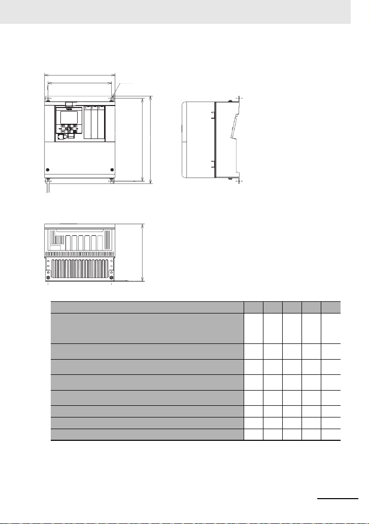
■ External dimensions (mm)
1
H1
H
D
2-ø7
W
Inverter Specifications
200 V Class:
400 V Class:
200 V Class:
400 V Class:
200 V Class:
400 V Class:
200 V Class:
400 V Class:
200 V Class:
400 V Class:
200 V Class: 3G3RX2-A2550 480 380 700 670 250
400 V Class: 3G3RX2-B4750, 3G3RX2-B4900 390 300 700 670 270
400 V Class: 3G3RX2-B411K, 3G3RX2-B413K 480 380 740 710 270
3G3RX2-A2004, 3G3RX2-A2007, 3G3RX2-A2015,
3G3RX2-A2022, 3G3RX2-A2037
3G3RX2-A4007, 3G3RX2-A4015, 3G3RX2-A4022,
3G3RX2-A4037
3G3RX2-A2055, 3G3RX2-A2075, 3G3RX2-A2110
3G3RX2-A4055, 3G3RX2-A4075, 3G3RX2-A4110
3G3RX2-A2150, 3G3RX2-A2185, 3G3RX2-A2220
3G3RX2-A4150, 3G3RX2-A4185, 3G3RX2-A4220
3G3RX2-A2300
3G3RX2-A4300
3G3RX2-A2370, 3G3RX2-A2450
3G3RX2-A4370, 3G3RX2-A4450, 3G3RX2-A4550
3G3RX2- W W1 H H1 D
150 130 255 241 140
210 189 260 246 170
245 229 390 376 190
300 265 540 510 195
390 300 550 520 250
15
Page 60

Inverter Specifications
■ Precaution on Installation
When you use an inverter of 3G3RX2-A2110 at Low Duty (LD) / Very Low Duty (VLD) or you use an
inverter of 3G3RX2-A2220 at Very Low Duty (VLD), install it with precautions shown in the following figures. Follow the below procedures and make the setting on your own.
User’s Screw
Procedure (4)
Procedure (1)
Screw
User’s Screw
Installation Procedure
Procedure (2)
Procedure (3)
Procedure (3)
Procedure (4)
Wall
Screw
Wall
Plan view / Cross-section view
* Set Low Duty [Ub-03] to 01 (LD) and set Very Low Duty to 00 (VLD) to complete the change.
16
Page 61

In the case of 3G3RX2-A2220
Installation Procedure
Procedure (1) M3×8 Screw
Procedure (1)
Procedure (1)
Procedure (2)
Procedure (2)
Spacer
Spacer
User’s Screw
User’s Screw
M3×8 Screw
Wall
Wall
Plan view / Cross-section view
* Set Very Low Duty to 00 (VLD) to complete the change.
Inverter Specifications
17
Page 62

Installation conditions
Screw clamp
Screw clamp
Screw clamp
Screw clam
p
30 cm or more
30 cm or more
5 cm
or more
5 cm
or more
5 cm
or more
5 cm
or more
10 cm or more
10 cm or more *1
*1 The following models need minimum 22 cm for maintenance.
· 3G3RX2-A2150 to 3G3RX2-A2220
· 3G3RX2-A4150 to 3G3RX2-A4220
The following models needs to be removed to replace aged parts.
· 3G3RX2-A2055 to 3G3RX2-A2110
· 3G3RX2-A4055 to 3G3RX2-A4110
3G3RX2-A2004 to 3G3RX2-A2550
3G3RX2-A4007 to 3G3RX2-A4550
3G3RX2-B4750 to 3G3RX2-B413K
Installation conditions
■Equipment Peripheral Dimension Conditions
Please note the installation method, the direction of installation!
• If the inverter is not installed vertically, its cooling performance may be degraded and tripping or
inverter damage may result.
• Install the inverter vertically and securely with screws or bolts on a surface that can bear the inverter
weight and is free from vibrations.
Surface on which to install the inverter
• The inverter will reach a high temperature (up to about 150°C) during operation. Install the inverter on
a vertical wall surface made of n onflamma ble mat erial (e. g., met al) t o avoid t he risk of fire. In additi on
be sure to confirm the structure to bear the Inverter weight.
• Keep sufficient distance between the inverter and other heat sources (e.g., braking resistors and
reactors) so that the heat discharged from the heat sources does not affect the inverter.
18
Page 63

Installation conditions
Control circuit terminal block
USB(Micro-B)
LCD operator
Optional cassette installed
Specification label
Main circuit terminal block
Backing plate
Terminal block cover
Heat sink
Air flow
Wall
Keep enough clearance between the inverter and the wiring
ducts located above and below the Inverter to prevent the
latter from obstructing the ventilation of the inverter.
Inverter
■Humidity
Avoid installing the inverter in a place where the relative humidity goes above or below the allowable
range (20% to 90% RH), as defined by the standard inverter specification. Avoid a place where the
inverter is subject to condensation.
Condensation inside the inverter will result in short circuits and malfunctioning of electronic parts. Also
avoid places where the inverter is exposed to direc t s un ligh t.
19
Page 64

Main circuit
ELB *1
Earth-leakage
breaker
Magnetic
contactor
MC
R/L1
S/L2
T/L3
R0
T0
U/T1
V/T2
W/T3
Control circuit
power supply
J51 connector
3-phase
AC motor *2
M
Main circuit
terminal section
3
Short bar or terminal
DisableDisable Enable PPPDRBN
Short bar
Internal EMC filter *3
3-phase
AC power
supply
200V class:
200 to 240Vac
400V class:
380 to 500Vac
D-class grounding
(200 V class)
C-class grounding
(400 V class)
Main circuit
■Main circuit Wiring Diagram
■Description of Main Circuit Terminal Block
20
*1. A Fuse is appleable in place of ELB.
*2. Driving a 200V motor using a 400V-class inverter may burn the motor.
*3. Factory setting is "Enable".
Terminal
symbol
R, S, T
(L1, L2, L3)
U, V, W
(T1, T2, T3)
PD, P
(+1, +)
P, R B
(+, RB)
P, N
(+, -)
Terminal name Description
Input terminal
for main power supply
Inverter output
terminal
DC reactor connection
terminal
Connection terminal for
external braking resistor
Connection terminal for
regenerative braking
unit
Inverter earth terminal The earth terminal for the Inverter case. Please connect this terminal
Connect to the AC power supply.
Connect to the 3-phase motor.
Remove the short bar between PD and P terminals, and connect the
optional reactor DCL for improving power factor.
Connect the optional external braking resistor for models equipped
with the braking resistor circuit. Model s no t equi pped with the braki ng
resistor circuit does not have the RB terminal.
Connect the optional regenerative braking unit BRD.
to the ground.
Conduct class-D ground work for 200V class, and class-C ground
work for 400V class.
Page 65

* The EMC filter is enabled/disabled by switching the short bar connector.
Power supplyPower supply
input wireinput wire
Motor outputMotor output
wirewire
R0
R
(L
1
)S(L2)T(L3)U(T1)V(T2)W(T3)
T0 G
P
(+ )N(-)
G
PD-P short barPD-P short bar
EMC filterEMC filter
enabledenabled
EMC filterEMC filter
disableddisabled
Charge lamp
(Turn-on while
energized)
OFF G ON
RB
(RB)
PD
(+ 1)
Control circuit
terminal block
Main circuit
terminal block
* Example of terminal arrangement.
Main circuit
21
Page 66

Main circuit
■Recommended Wire Diameter, Wiring Tools, and Crimping Terminals
200V class
Model
Rated
3G3RX2
settings
A2004
A2007
A2015
A2022
A2037
A2055
A2075
A2110
A2150
A2185
A2220
A2300
A2370
A2450
A2550
Note 1. The wire diameter described in the above table shows the design value of the HIV line (heat-resistant 75 °C) standard.
ND
VLD
ND
VLD
ND
VLD
ND
VLD 10 (5.3) 10 (5.3) 10 (5.3) 5.5-4/5.5-4
ND
VLD
ND
VLD
ND
VLD 6 (13.3) 6 (13.3) 14-5/8-5
ND 6 (13.3)
VLD
ND 4 (21.2)
VLD
ND 3 (26.7)
VLD 1 (42.4) 1 (42.4) 60-6/14-6
ND 1 (42.4)
VLD 2/0 (67.4) 2/0 (67.4) 70-8/14-6
ND 2/0 (67.4)
VLD
ND 4/0 (107.2)
VLD
ND
VLD 2/0×2 (67.4×2) 70-8/22-8
ND 350kc (177)
VLD
2. When connecting wires to the main circuit terminal block, use the Round crimp terminal (UL compliant product) suitable for the
wire used. Crimp terminals should be crimped using the Crimping tool recommended by the crimping terminal manufacturer.
Power line
2
AWG (mm
R, S, T, U, V, W, P,
PD, N
14 (2.1) 14 (2.1) 14 (2.1) M4 2-4/2-4 1.4LD
14 (2.1) 14 (2.1) 14 (2.1) M4 2-4/2-4 1.4LD
14 (2.1) 14 (2.1) 14 (2.1) M4 2-4/2-4 1.4LD
14 (2.1) 14 (2.1) 14 (2.1)
10 (5.3) 10 (5.3) 10 (5.3) M4 5.5-4/5.5-4 1.4LD
8 (8.4) 8 (8.4) 8 (8.4) M5 8-5/8-5 3.0LD
8 (8.4)
4 (21.2) 4 (21.2) 22-6/14-6
3 (26.7) 3 (26.7) 38-6/14-6
1/0×2 (53.5×2) 60-8/22-8
1/0×2 (53.5×2) 60-8/22-8
1/0×2 (53.5×2)
3/0×2 (85.0×2) 80-10/38-8
Ground line
)
AWG (mm
6 (13.3)
6 (13.3)
6 (13.3)
6 (13.3)
6 (13.3)
4 (21.2) --- M8
4 (21.2) --- M8
4 (21.
3 (26.7) --- M10
Braking resis-
tor AWG
2
between
)
P and RB (mm
8 (8.4)
6 (13.3)
4 (21.2)
3 (26.7)
1 (42.4)
2) --- M
line terminal
2
)
Screw size
of power
M4
M5
M6
M6
M6
M8
8
Crimping terminal
power line/ground
2-4/2-4
8-5/8-5
14-6/14-6
22-6/14-6
38-6/14-6
60-8/14-6
70-8/22-8
100-8/22-8
60-8/22-8
180-10/38-8
line
Tightening
torque N·m
1.4LD
3.0LD
4.0LD
2.5 to 3.0LD
2.5 to 3.0LD 2 (33.6) 2 (33.6)
5.5 to 6.6LD 1/0 (53.5) 1/0 (53.5)
6.0LD
15.0LD
6.0 to 10.0LD
19.6LD
22
Page 67

Main circuit
400V class
Model
Rated
3G3RX2
settings
ND
A4007
VLD
ND
A4015
VLD
ND
A4022
VLD
ND
A4037
VLD 12 (3.3) 12 (3.3) 12 (3.3) 5.5-4/5.5-4
ND
A4055
VLD 10 (5.3) 10 (5.3) 10 (5.3)
ND
A4075
VLD 8 (8.4) 8 (8. 4) 8 (8.4) 8-5/8-5
ND
A4110
VLD
ND
A4150
VLD
ND 8 (8.4)
A4185
VLD
ND 6 (13.3)
A4220
VLD
ND 3 (26.7)
A4300
VLD 1 (42.4) 60-8/14-8
ND
A4370
VLD
ND 1 (42.4)
A4450
VLD 2/0 (67.4) 70-8/14-8
ND 2/0 (67.4)
A4550
VLD
ND
B4750
VLD
ND
B4900
VLD 2/0×2 (67.4×2) 70-10/38-8
ND
B411K
VLD 3/0×2 (85.0×2) 80-10/38-8
B413K
Note 1. The wire diameter described in the above table shows the design value of the HIV line (heat-resistant 75 °C) standard.
ND 3/0×2 (85.0×2)
VLD 250kc×2 (127×2) 150-10/38-8
2. When c onnec t ing wire s to the main circuit terminal block, use the Round crimp terminal (UL compliant product) suitable for the
wire used.
Crimp terminals should be crimped using the Crimping tool recommended by the crimping terminal manufacturer.
Power line
2
AWG (mm
R, S, T, U, V, W, P,
)
PD, N
Ground line
AWG (mm
2
)
P and RB (mm
Braking resis-
tor AWG
between
Screw size
line terminal
2
)
of power
Crimping terminal
power line/ground
14 (2.1) 14 (2.1) 14 (2.1) M4 2-4/2-4 1.4LD
14 (2.1) 14 (2.1) 14 (2.1) M4 2-4/2-4 1.4LD
14 (2.1) 14 (2.1) 14 (2.1) M4 2-4/2-4 1.4LD
14 (2.1) 14 (2.1) 14 (2.1)
12 (3.3) 12 (3.3) 12 (3.3)
10 (5.3) 10 (5.3) 10 (5.3)
M4
M5 5.5-5/5.5-5 3.0LD
M5
2-4/2-4
5.5-5/5.5-5
8 (8.4) 8 (8.4) 8 (8.4) M6 8-6/8-6 4.0LD
8 (8.4) 8 (8.4) 8 (8.4) M6 8-6/8-6 4.0LD
6 (13.3) 6 (13.3) 14-6/8-6
4 (21.2) 4 (21.2) 22-6/8-6
8 (8.4)
8 (8.4)
8 (8.4)
6 (13.3)
M6
M6
6 (13.3) --- M8
8-6/8-6
14-6/8-6
38-8/14-8
1 (42.4) 6 (13.3) --- M 8 60-8/14-8 15.0LD
6 (13.3) --- M8
1/0×2 (53.5×2) 60-8/22-8
4 (21.2) --- M8
60-8/14-8
70-8/22-8
1/0×2 (53.5×2) 4 (21.2) --- M10 60-10/22-8 6.0 to 10.0LD
1/
0
×2 (53.5×2)
2/0×2 (67.4×2)
3 (26.7) --- M10
2 (33.6) --- M10
2 (33.6) --- M10
60-10/38-8
70-10/38-8
80-10/38-8
line
Tightening
torque N·m
1.4LD
3.0LD
4.0LD
4.0LD
6.0LD 2 (33.6)
6.0 to 10.0LD 1/0 (53. 5)
6.0 to 10.0LD
6.0 to 10.0LD
19.6LD
19.6LD 4/0×2 (107×2) 100-10/38-8
23
Page 68

Main circuit
■Applicable Breakers
200V class
• When inverter ND rating setting
Applicable
Model
3G3RX2
A2004 0.4 EB-30E 5 HS8 HS8 EB-30E 5 HS8 HS8
A2007 0.75 EB-30E 10 HS8 HS8 EB-30E 5 HS8 HS8
A2015 1.5 EB-30E 15 HS8 HS8 EB-30E 10 HS8 HS8
A2022 2.2 EB-30E 20 HS8 HS8 EB-30E 15 HS8 HS8
A2037 3.7 EB-30E 30 HS8 HS20 EB-30E 20 HS8 HS20
A2055 5.5 EB-50E 40 HS20 HS25 EB-30E 30 HS8 HS20
A2075 7.5 EB-50E 50 HS35 HS35 EB-50E 40 HS20 HS25
A2110 11 EB-100E 75 HS50 H65C EB-100E 60 HS35 HS50
A2150 15 RXK125-S 125 H65C H80C EB-100E 100 HS50 H65C
A2185 18.5 RXK125-S 125 H80C H100C EB-100E 100 HS50 H65C
A2220 22 EXK225 150 H80C H125C RXK125-S 125 H65C H80C
A2300 30 EXK225 200 H125C H150C EXK225 150 H80C H125C
A2370 37 RXK250-S 250 H150C H200C EXK225 200 H100C H125C
A2450 45 EX400 300 H200C H250C EXK225 225 H125C H150C
A2550 55 EX400 400 H200C H300C EX400 300 H150C H250C
Without power factor improvement rea ctor
motor
Earth-leakage breaker
(kW)
Example
of model
(ELB)
Applicable instrument (input voltage 200 to 220V)
Magnetic contactor
Rated
current
(MC)
AC-1 AC-3
With power factor improvement r eactor
(3G3AX-AL or 3G3AX-DL)
Earth-leakage breaker
(ELB)
Example
of model
Rated
current
Magnetic contactor
AC-1 AC-3
(MC)
• When inverter LD/VLD rating setting
Applicable
Model
3G3RX2
A2004 0.75 EB-30E 10 HS8 HS8 EB-30E 5 HS8 HS8
A2007 1.5 EB-30E 15 HS8 HS8 EB-30E 10 HS8 HS8
A2015 2.2 EB-30E 20 HS8 HS8 EB-30E 15 HS8 HS8
A2022 3.7 EB-30E 30 HS8 HS20 EB-30E 20 HS8 HS20
A2037 5.5 EB-50E 40 HS20 HS25 EB-30E 30 HS8 HS20
A2055 7.5 EB-50E 50 HS35 HS35 EB-50E 40 HS20 HS25
A2075 11 EB-100E 75 HS50 H65C EB-100E 60 HS35 HS50
A2110 15 RXK125-S 125 H65C H80C EB-100E 100 HS50 H65C
A2150 18.5 RXK125-S 125 H80C H100C EB-100E 100 HS50 H65C
A2185 22 EXK225 150 H80C H125C RXK125-S 125 H65C H80C
A2220 30 EXK225 200 H125C H150C EXK225 150 H80C H125C
A2300 37 RXK250-S 250 H150C H200C EXK225 200 H100C H125C
A2370 45 EX400 300 H200C H250C EXK225 225 H125C H150C
A2450 55 EX400 400 H200C H300C EX400 300 H150C H250C
A2550 75 EX600B 500 H300C H400C EX400 400 H200C H300C
Note 1. The models described in the table are examples of selection. When using the device, cho ose a model that has appropriate
breaking capacity and sens itive current by taking short circuit current and relev ant laws and regulations into consideration
based on the rated current shown in the table.
2. The applicable moto r capacity is a selection example wh en standard motors 4-pole motor mo del 60HZ 200VAC (200V class)
is used.
3. The electric durability ensured when the magnetic contactor is used in AC-1 class is 500,000 times, while emergency stop
during motor operation is 25 times.
4. If there is emergency stop during motor drive or commercial operation is performed, choose the magnetic contactor on the
motor side in AC-3 class against the rated current of motor.
5. If the rated capacity of inverter is larger than the motor capacity, choose instruments based on the inverter model.
Without power factor improvement rea ctor
motor
Earth-leakage breaker
(kW)
Example
of model
(ELB)
Applicable instrument (input voltage 200 to 220V)
Magnetic contactor
Rated
current
(MC)
AC-1 AC-3
With power factor improvement r eactor
(3G3AX-AL or 3G3AX-DL)
Earth-leakage breaker
(ELB)
Example
of model
Rated
current
Magnetic contactor
AC-1 AC-3
(MC)
24
Page 69

400V class
• At inverter ND rating setting
Applicable
Model
3G3RX2
A4007 0.75 EX50C 5 HS8 HS8 EX50C 5 HS8 HS8
A4015 1.5 EX50C 10 HS8 HS8 EX50C 5 HS8 HS8
A4022 2.2 EX50C 10 HS8 HS8 EX50C 10 HS8 HS8
A4037 3.7 EXK50-C 15 HS8 HS10 EX50C 10 HS8 HS8
A4055 5.5 EXK50-C 20 HS8 HS20 EXK50-C 15 HS8 HS20
A4075 7.5 EXK50-C 30 HS8 HS25 EXK50-C 20 HS8 HS20
A4110 11 EXK50-C 40 HS20 HS35 EXK50-C 30 HS8 HS25
A4150 15 EXK50-C 50 HS25 HS50 EXK50-C 40 HS20 HS35
A4185 18.5 EXK100-C 75 HS35 HS50 EXK50-C 50 HS20 HS35
A4220 22 EXK100-C 75 HS50 H65C EXK60-C 60 HS35 HS50
A4300 30 EXK100-C 100 HS50 H80C EXK100-C 75 HS50 H65C
A4370 37 RXK125-S 125 H80C H100C EXK100-C 100 HS50 H65C
A4450 45 EXK225 150 H80C H125C RXK125-S 125 H65C H80C
A4550 55 EXK225 200 H100C H125C EXK225 150 H80C H100C
B4750 75 RXK250-S 250 H150C H200C EXK225 200 H100C H125C
B4900 90 EX400 300 H200C H250C EXK225 225 H125C H150C
B411K 110 EX400 400 H200C H300C EX400 300 H150C H250C
B413K 132 EX600B 500 H250C H300C EX400 350 H200C H250C
Without power factor improvement reactor
motor
Earth-leakage breaker
(kW)
Example
of model
(ELB)
Applicable instrument (input voltage 200 to 220V)
Magnetic contactor
Rated
current
(MC)
AC-1 AC-3
With power factor improvement reactor
(3G3AX-AL or 3G3AX-DL)
Earth-leakage breaker
(ELB)
Example
Rated
of model
current
Main circuit
Magnetic contactor
(MC)
AC-1 AC-3
• At inverter LD/VLD rating setting
Applicable
Model
3G3RX2
A4007 1.5 EX50C 10 HS8 HS8 EX50C 5 HS8 HS8
A4015 2.2 EX50C 10 HS8 HS8 EX50C 10 HS8 HS8
A4022 3.7 EXK50-C 15 HS8 HS10 EX50C 10 HS8 HS8
A4037 5.5 EXK50-C 20 HS8 HS20 EXK50-C 15 HS8 HS20
A4055 7.5 EXK50-C 30 HS8 HS25 EXK50-C 20 HS8 HS20
A4075 11 EXK50-C 40 HS20 HS35 EXK50-C 30 HS8 HS25
A4110 15 EXK50-C 50 HS25 HS50 EXK50-C 40 HS20 HS35
A4150 18.5 EXK100-C 75 HS35 HS50 EXK50-C 50 HS20 HS35
A4185 22 EXK100-C 75 HS50 H65C EXK60-C 60 HS35 HS50
A4220 30 EXK100-C 100 HS50 H80C EXK100-C 75 HS50 H65C
A4300 37 RXK125-S 125 H80C H100C EXK100-C 100 HS50 H65C
A4370 45 EXK225 150 H80C H125C RXK125-S 125 H65C H80C
A4450 55 EXK225 200 H100C H125C EXK225 150 H80C H100C
A4550 75 EX400 250 H150C H200C EXK225 200 H100C H125C
B4750 90 EX400 300 H200C H250C EXK225 225 H125C H150C
B4900 110 EX400 400 H200C H300C EX400 300 H150C H250C
B411K 132 EX600B 500 H250C H300C EX400 350 H200C H250C
B413K 160 EX600B 600 H400C H400C EX400 400 H250C H300C
Note 1. The models described in the table are examples of selection. When using the device, choose a model that has appropriate
breaking capacity and sensitive current by taking short circuit current and relevant laws and regulations into consideration
based on the rated current shown in the table.
2. The applicable motor capacity is a selection example when standard motors 4-pole mot or model 60HZ 200VAC (200V class)
is used.
3. The electric durability ensured when the magnetic contactor is used in AC-1 class is 500,000 times, while emergency stop
during motor operation is 25 times.
4. If there is emergency stop during motor drive or commercial operation is performed, choose the magnetic contactor on the
motor side in AC-3 class against the rated current of motor.
5. If the rated capacity of inverter is larger than the motor capacity, choose instruments based on the inverter model.
Without power factor improvement reactor
motor
Earth-leakage breaker
(kW)
Example
of model
(ELB)
Applicable instrument (input voltage 200 to 220V)
Magnetic contactor
Rated
current
(MC)
AC-1 AC-3
With power factor improvement reactor
(3G3AX-AL or 3G3AX-DL)
Earth-leakage breaker
(ELB)
Example
of model
Rated
current
Magnetic contactor
AC-1 AC-3
(MC)
25
Page 70

Control circuit
Control circuit
terminal area
Backup
24V power supply
terminal
P+
P-
1/RS
2/SCHG
3/JG
4/FRS
5/2CH
6/CF1
7/CF2
8/RV
9/FW
A/EXT
B/USP
COM
CM1
Interface
24V power supply terminal
P24
H
Ai1
Ai2
Ai3
L
(+)
(-)
(± 10V)
(0V)
TH+
AL2
AL1
AL0
16A
16C
11/RUN
12/FA1
13/FA2
14/IRDY
15/OL
CM2
FM
CM1
Ao1
Ao2
L
SP
SN
SP
SN
RP
P24S
STC
CMS
ST1
ST2
ED+
ED-
TH-
L
L
10V
10V
20mA
10V
10V
20mA
20mA
Voltage input
Current input
Voltage input
Current input
Input terminal
Thermistor
STO input
STO confirmation output
Analog
input 3
Analog
input 2
Analog
input 1
P24
CM1
DC24V
P24
CM1
P24
IN
EX
Source
Sink
(SW5)
(SW6)
(SW1)
(SW2)
(SW3)
(SW4)
16/Z S
Operation section
USB
RJ45
P
C (P
roDriveNext)
LCD operator
20mA
You can switch between
the sink logic and
source logic for input
terminals by using SW6.
* The signal ground for RS485
terminal is CM1
RS485 terminal
Modbus
communication
Output terminals
* Supporting sink/source
Relay 1A contact
Alarm relay 1C contact
Control circuit
■Outline of control circuit
26
Page 71

■Input terminals
• All COM terminals are at the same potential.
• When connecting a power supply between 1-9, A, B and COM, switch SW5 to the external power
supply (EX).
• You can switch between the sink/source logic of input terminals by using SW6.
(Wiring example)
Control circuit terminal
SW5
input
3
B
[USP]
• Indicates the factory default setting.
Input
Digital
terminal
input
A
[EXT]
Contact
Contact/
pulse
Common
9
[FW]
Terminal
symbol
9, 8, 7, 6,
5, 4, 3, 2,
1
A
B
COM
8
[RV]
Terminal
name
Input
terminal
Pulse
input-A
Pulse
input-B
Common
for input
terminal
[CF1]
[CF2]
You can select terminal functions
using the parameter settings corresponding to each terminal. You can
switch between the sink logic and
source logic by switching SINK/SRC
of SW6.
This is a terminal for pulse input. A
and B terminals can be used also as
an input terminal.
Terminal functions are selectable
according to the parameter settings
for each terminal.
The maximum input pulse rate is
32kpps.
Common terminals for digital input terminals (1, 2, 3, 4, 5, 6, 7, 8, 9, A, B).
There are three COM terminals.
6
7
5
[2CH]
Description Electrical characteristics
4
[JG]
[FRS]
Voltage between each input/COM
• ON voltage Min. DC18V
• OFF voltage Max. DC3V
• Maximum allowable voltage
DC27V
• Load current 5.6mA (at DC27V)
Voltage between each input/COM
• ON voltage Min. DC18V
• OFF voltage Max. DC3V
• Maximum allowable voltage
DC27V
• Load current 5.6mA (at DC27V)
• Maximum 32kpps pulse input
Control circuit
area
2
[SCHG]
[RS]
SW6
COMCOMCOM
1
27
Page 72

Control circuit
Forward Reverse Description
OFF OFF No command
ON OFF Forward rotation command operation
OFF ON Reverse rotation command operation
ON ON No command (inconsistent logic)
* Setting CF3 and 4 allows you to set up to 16-speed.
Multi-
speed-1
CF1
Multi-
speed-2
CF2
Description
OFF OFF The set frequency source is enabled.
ON OFF The frequency source of [Ab-11] is
enabled.
OFF ON The frequency source of [Ab-12] is
enabled.
ON ON The frequency source of [Ab-13] is
enabled.
■Initial terminal function
This section describes the function of the initial shipment value. Please check the detailed function in
the user's manual (I620-E1).
[RS:028] Reset
• Reset at every trip.
[SCHG:015] Command source change
• Change to the main speed command
[AA101](OFF) or sub-speed command
[AA102](ON).
[JG:029] Jogging
• Run at a frequency of [AG-20] upon receipt of
the operation command by [JG]ON.
[FRS:032] Free-run stop
• [FRS] ON sets the motor in a free-run state.
[2CH:031] Two-step acceleration/deceleration
• [2CH]ON enables acceleration/deceleration
time-2 [AC124][AC126].
[EXT:033] External trip
• [EXT] ON issues Trip [E012].
[FW:001] Forward rotation and [RV:002] Reverse
rotation
[CF1:003] Multispeed-1 and [CF2:004] Multispeed-2 commands
[USP:034] Unattended start protection
• In a [USP] ON state, if an operation command
has been input before the power supply is ON,
Trip [E013] is issued.
28
Page 73

■Output terminals
(Wiring example)
Control circuit
Output
Digital
terminal
output
Open
collector
Relay
Terminal
Terminal
symbol
15, 14
13, 12
11
CM2 Common
16A
16C
AL0
AL1
AL2
name
Output
terminal
for output
terminal
1a relay
terminal
1c relay
terminal
Description Electrical characteristics
You can select terminal functions
using the parameter settings corresponding to each terminal.
These terminals can be used both in
sink logic or source logic.
Common terminals for output terminals 11-15
A relay for contact A output. Maximum capacity of contact
A relay for contact C output. Maximum capacity of contact
Open collector output
• Between each terminal and CM2
• Voltage drop at ON: 4V or below
• Maximum allowable voltage: 27V
• Maximum allowable current:
50mA
• AC250V, 2A (resistance)
• AC250V, 1A (induction)
Minimum capacity of contact
•DC1V, 1mA
AL1/AL0:
• AC250V, 2A (resistance)
• AC250V, 0.2A (induction)
AL2/AL0:
• AC250V, 1A (resistance)
• AC250V, 0.2A (induction)
Minimum capacity of contact (common)
• AC100V, 10mA
• DC5V, 100mA
29
Page 74

Control circuit
Power
supply
Status AL0-AL1 AL0-AL2
ON Normal Open Close
ON Trip Close Open
OFF --- Open Close
Power
supply
Status AL0-AL1 AL0-AL2
ON Normal Close Open
ON Trip Open Close
OFF --- Open Close
■Initial terminal function
This section describes the function of the initial shipment value. Please check the detailed function in
the user's manual (I620-E1).
[RUN:001] During operation signal
• Turns ON during operation (PWM output).
[FA1:002] Frequency reached signal
• Turns ON when the output frequency reaches
the command frequency.
[FA2:003] Frequency reached signal 2
• Turns ON when the output frequency reaches
the set frequency [CE-10]-[CE-13].
[IRDY:007] Operation ready completion
• Turns ON when operation is ready.
[OL:035] Overload advance notice
• Turns ON when current exceeds the level of
overload advance notice.
[ZS:040] 0 Hz detection signal
• Turns ON when the output frequency goes
below the 0-Hz detection value level [CE-33].
About [AL] operation
• When [CC-17] = 00
• When [CC-17] = 01
30
Page 75
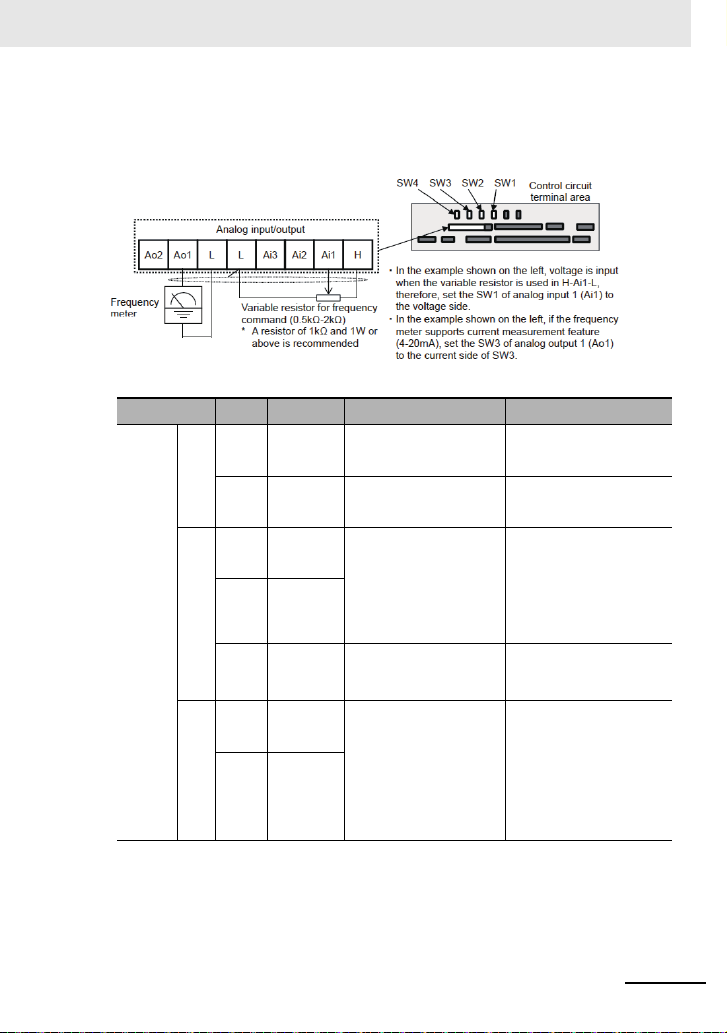
■Analog input/output
(Wiring example)
Control circuit
Analog input
terminal for
switching
voltage and
current
Termina l
symbol
L Analog
Power
supply
H Power supply
Ai1 Analog
Ai2 Analog
Analog
input
Ai3 Analog
Ao1 Analog
Ao2 Analog
Analog
output
Terminal name Description Electrical characteristics
Common terminals for analog input
power common
for setting speed
input terminal 1
(voltage/current
switching SW1)
input terminal 2
(voltage/current
switching SW2)
input terminal 3
output terminal 1
(voltage/current
switching SW3)
output terminal 2
(voltage/current
switching SW4)
terminals (Ai1, Ai2, Ai3) and analog
output terminals (Ao1, Ao2). There
are two L terminals.
This is a DC10V power supply. It is
used when using analog input terminals (Ai1, Ai2, Ai3) and variable
resistor for inputting voltage.
For Ai1 and Ai2, DC0-10V voltage
input and 0-20mA current input can
be switched using a switch for use.
It can be used for input frequency
command or feedback.
-10V to 10V voltage input is available. It can be used for input frequency command or feedback.
For Ao1 and Ao2, DC0-10V voltage
output and 0-20mA current output
can be switched using a switch as
output of information monitor data of
the inverter.
Maximum allowable input current
20mA
In the case of voltage input:
• Input impedance about 10kΩ
• Allowable input voltage DC-0.3V to
12V
In the case of current input:
• Input impedance about 100Ω
• Maximum allowable input current
24mA
Only voltage input:
• Input impedance about 10kΩ
• Allowable voltage input -12V to
12V
In the case of voltage output:
• Maximum allowable output current
2mA
• Output voltage accuracy ±10%
(ambient temperature: 25°C±10°C)
In the case of current input:
• Allowable load impedance 250Ω or
below
• Output current accuracy: ±20%
(ambient temperature: 25°C±10°C)
31
Page 76

Control circuit
DC5V
1kΩ
2kΩ
TH-
TH+
Thermistor
■External thermistor
(Wiring example)
External thermistor
terminals
TH-TH+
Thermistor
Analog
terminal
input
Terminal
symbol
TH+
TH-
Control circuit terminal
• Twist the cables connected from a thermistor to the TH
• Since very low current flows through the cables
Thermistor
• The length of the cables connected to the thermistor
Termina l
name
External
Connect to an external thermistor to make
thermistor
the inverter trip if an abnormal temperature
input
is detected.
Connect the thermistor to TH+ and TH-.
Common
The impedance to detect temperature
for external
errors can be adjusted within the range 0Ω
thermistor
to 10,000Ω.
[Recommended thermistor properties]
Allowable rated power: 100 mW or more
Impedance at temperature error: 3kΩ
terminal only between TH+ and TH-, and separate the
twisted cables from other cables.
connected to the thermistor, separate the cables from
those (power line cables) connected to the main circuit.
must be 20 m or less.
Description Electrical character ist ics
DC 0 to 5V
[Input circuit]
32
Page 77
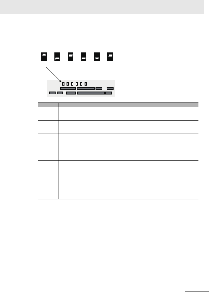
■Description of switches
Control circuit terminal area
SW4
SW3
SW2
SW1
SW5
SW6
10V
20mA
10V
20mA
10V
20mA
10V
20mAINEX
SINK
SRC
Ao2 Ao1 Ai2
Ai1 P.SE
(SW4) (SW3) (SW2) (SW1) (SW5) (SW6)(SW4) (SW3) (SW2) (SW1) (SW5) (SW6)
* Using a switch under power-on condition may cause
failure. Use the switch only after turning off the
power and confirming that the POWER lamp on the
operator keypad is off.
(Factory setting)
Control circuit
Indication SW name Description
Ai1
Ai2
Ao1
Ao2
Analog input 1 switch
Analog input 2 switch
Analog output 1 switch
Analog output 2 switch
Switching the method of
power supply to the input
terminals
Switch of sink/source for
the input terminals
(SW1)
(SW2)
(SW3)
(SW4)
P.SEL
(SW5)
SRC/SINK
(SW6)
Switches input specification of analog input 1 (Ai1 terminal).
10V: Voltage input is available.
20mA: Current input is available.
Switches input specification of analog input 2 (Ai2 terminal).
10V: Voltage input is available.
20mA: Current input is available.
Switches output specification of analog output 1 (Ao1 terminal).
10V: Output changes to voltage output.
20mA: Output changes to current output.
Switches output specification of analog output 2 (Ao2 terminal).
10V: Output changes to voltage output.
20mA: Output changes to current output.
Switches the method of power supply to the input terminals.
IN: Drives the input terminals using the internal power supply.
EX: Use an external power supply to drive input terminals.
(In the case of EX, a power supply is required between the input terminals
and COM.)
Switches the sink/source logic for input terminals.
This switch is enabled when SW5 is IN.
SINK: Enables sink logic.
SRC: Enables source logic.
33
Page 78

Control circuit
(+) (- )
Control circuit terminal area
Modbus communication
RPSNSPSNSPCM1
Connect CM1 to the SG
(signal ground) of an
external device.
When enabling the terminating
resistor, short RP-SN.
■RS485 Communication Terminal
SP and SN terminals with the same names are internally connected respectively, so they can be used
for wiring multiple terminals.
RS485 com-
munication
Serial
communi-
cation
Terminal
symbol
SP
SN
RP
(CM1)
Termina l
name
SP terminal: RS-485 differential (+) signal
SN terminal: RS-485 differential (-) signal
RP terminal: Connect to SP via tile terminating
RS-485
resistor
terminal
CM1 terminal: Connect with the signal ground
for Modbus
communi-
cation
of an external communication device.
(also used by FM terminal)
There are two SP terminals and SN terminals
each, which are connected internally.
Maximum baud rate is 115.2kbps.
Description
Electrical character-
istics
Equipped with terminating resistor
(120Ω)
Enable: Short RP-SN
Disable: Open RP-SN
34
Page 79

■STO terminal, EDM terminal
Control circuit terminal area
Wiring condition when shipped.
STO terminal
ST2 STC ST1
P24S STC CMS
Control circuit terminal area
EDM terminal
Wiring example
ED+ ED-
Load
Term inal
symbol
P24S 24V output terminal (for STO
CMS 24V output terminal common
STC Input logic switching terminal A logic switching terminal for STO input.
ST1/ST2 STO input terminals Input terminals of STO. Voltage between ST1 and STC/ST1
ED+ EDM signal output terminal (+) A plus terminal of EDM signal (STO status moni-
ED- EDM signal output terminal (-) A minus terminal of EDM signal (STO status mon-
Control circuit
STO terminal and EDM terminal used with the STO function. For details on the STO function, refer to
the User's Manual (I620-E1).
Terminal name Description Electrical chara cter ist ics
input only)
(for STO input only)
A DC24V power supply for contact signals dedicated for ST1/ST2 terminals. The common terminal is CMS.
A common terminal for DC24V power supply for
contact signals dedicated for ST1/ST2 terminals.
You can change the input logic changing the connecting point of short-circuit line.
When an external power supply is used, remove
the short-circuit line and use this terminal as the
input common for ST1/ST2.
toring).
itoring).
Maximum output current: 100mA
<For sink logic>
Short-circuit line: Connect between
P24S and STC
<For source logic>
Short-circuit line: Connect between
CMS and STC
and STC
• ON voltage: Min.DC15V
• OFF voltage Max. DC5V
• Maximum allowable voltage DC27V
• Load current 5.8mA (at DC27V)
Internal resistance: 4.7kΩ
Open collector output
• Between ED+ and ED-
• Voltage drop at ON: 4V or less
• Maximum allowable voltage: 27V
• Maximum allowable current: 50mA
35
Page 80

Control circuit
φd
φD
L1
L2
2.5 mm
Press in the
orange portion
using a slotted
screwdriver
Insert the wire
Extract the slotted
driver to fix the wire
■Recommended Terminal for wiring
• For the convenience of wiring and improvement of connection reliability, it is recommended to use
rod terminals with the following specifications.
• For the control circuit terminal block, spring type terminal blocks are mounted.
Rod terminal with Sleeve
Wire size
2
mm
(AWG)
0.25 (24) AI 0,25-8YE 8 12.5 0.8 2.0
0.34 (22) AI 0,34-8TQ 8 12.5 0.8 2.0
0.5 (20) AI 0,5-8WH 8 14 1.1 2.5
0.75 (18) AI 0,75-8GY 8 14 1.3 2.8
* Manufacturer: Phoenix Contact.
Caulking tool CRIMPFOX UD 6-4 or CRIMPFOX ZA 3
Rod terminal model * L1 [mm] L2 [mm] φd [mm] φD [mm]
■Method of wiring/detaching wires
1 Press in the orange portion on the control circuit terminal block using a slotted screwdriver
(2.5mm or less in width).
(The wire insertion slot opens.)
2 While pressing the slotted screwdriver in the terminal block, insert the wire or rod terminal into
the wire insertion slot (round hole).
3 Extract the slotted driver to fix the wire.
Also when extracting the wire, extract it while the orange portion is pressed in with the slotted
screwdriver (the wire insertion slot is open).
36
Page 81

Conditions of conformity of EU directives
Conditions of conformity of EU directives
■Specifications
EMC EN61800-3:2004/AI:2012
Machinery IEC61800-5-2:2016
• This is a product designed for industrial environments.
Use in residential area may cause radio interference, in which case the user may be required to take
adequate measures to reduce interferense.
• This type of PDS is not intended to be used on a low-voltage public network which supplies domestic
premises.
■Manufacturer and EU Representative
Manufacturer: OMRON Corporation
Representative and Importer in EU: OMRON EUROPE B.V.
GENERAL:
3G3RX2 series Type inverter is open type AC Inverter with three phase input and three phase output. It
is intended to be used in an enclosure. It is used to provide both an adjustable voltage and adjustable
frequency to the ac motor. The inverter automatically maintains the required volts-Hz ratio allowing the
capability through the motor speed range. It is multi-rated device and the ratings are selectable according to load types by operator with key pad operation.
■Compatibility Conditions of EMC Directives
CAUTION for EMC
(Electromagnetic Compatibility)
EN ISO 13849-1:2014
EN61800-5-1:2007
Shiokoji Horikawa, Shimogyo-ku, Kyoto, 600-8530 Japan
Wegalaan 67-69,2132 JD Hoofddorp, The Netherlands
3G3RX2 series inverter conforms to requirements of Electromagnetic Compatibility (EMC) Directive
(2014/30/EU). However, when using the inverter in Europe, you must comply with the following specifications and requirements to meet the EMC Directive and other standards in Europe:
1. Power supply requirements
a) Voltage fluctuation must be -15% to +10% or less.
b) Voltage imbalance must be ±3% or less.
c) Frequency variation must be ±4% or less.
d) Total harmonic distortion (THD) of voltage must be±10% or less.
2. Installation requirement
a) 3G3RX2 series includes a built-in EMC filter. The built-in EMC filter must be activated.
This equipment must be installed, adjusted, and maintained by qualified engineers who have
expert knowledge of electric work, inverter operation, and the hazard ouscircumstances that
can occur. Otherwise, personal injury may result.
37
Page 82

Conditions of conformity of EU directives
b) According to EN61800-3 it is mandatory to mention that any inverter with only C3 filter inside
may NOT be connected to a low voltage public power supply in residential areas since for these
installations C1 is required.
c) In case of external filter for C2, an additional note is required according to EN61800-3 that “this
product may emit high frequency interference in residential areas which may require additional
EMC measures”.
d) According to the EN6100-3-12, an additional AC reactor or DC choke should be installed for
reducing harmonics in power line.
3. Wiring requirements
a) A shielded wire (screened cable) must be used for motor wiring, and the length of the cable must
be according to the following table.
b) The carrier frequency must be set according to the following table to meet an EMC requirement.
c) The main circuit wiring must be separated from the control circuit wiring.
4. Environmental requirements (to be met when a filter is used)
a) 3G3RX2 series inverter that is activated built-in EMC filter must be according to 3G3RX2 series
specifications.
Tab le 1
Model
3G3RX2
A2004 C3 10m 2kHz -- -- -- -A2007 C3 10m 2kHz A4007 C3 10m 2kHz
A2015 C3 10m 2kHz A4015 C3 10m 2kHz
A2022 C3 10m 2kHz A4022 C3 10m 2kHz
A2037 C3 10m 2kHz A4037 C3 10m 2kHz
A2055 C3 5m 2kHz A4055 C3 5m 2kHz
A2075 C3 5m 2kHz A4075 C3 5m 2kHz
A2110 C3 5m 2kHz A4110 C3 5m 2kHz
A2150 C3 10m 1kHz A4150 C3 10m 2kHz
A2185 C3 10m 1kHz A4185 C3 10m 2kHz
A2220 C3 10m 1kHz A4220 C3 10m 2kHz
A2300 C3 5m 2kHz A4300 C3 5m 2kHz
A2370 C3 5m 2kHz A4370 C3 5m 2kHz
A2450 C3 5m 2kHz A4450 C3 5m 2kHz
A2550 C3 5m 2kHz A4550 C3 5m 2kHz
Cat. Cable length
--- --- --- --- B4750 C3 3m 2kHz
--- --- --- --- B4900 C3 3m 2kHz
--- --- --- --- B411K C3 3m 2kHz
--- --- --- --- B413K C3 3m 2kHz
frequency
Carrier
Model
3G3RX2
Cat. Cable length
Carrier
frequency
■Conditions of Electrical Safety (LVD)
The condition in the next section UL standard explain the condition of the electrical safety. It is necessary to comply with the description items such as temperature condition, installation condition etc.
38
Page 83

Compatibility Conditions of UL/CSA Standards
Compatibility Conditions of UL/CSA St andards
■Standards
US UL61800-5-1
CA CSA 22.2 No.274
FS IEC61800-5-2:2016 STO SIL3
UL CAUTION
GENERAL:
Model 3G3RX2 series inverter is an open type AC Inverter with three phase input and three phase out-
put. It is intended to be used in an enclosure. It is used to provide both an adjustable voltage and
adjustable frequency to the ac motor. The inverter automatically maintains the required volts-Hz ratio
allowing the capability through the motor speed range. It is a multi-rated device and the ratings are
selectable according to load types by operator with key pad operation.
Markings:
Maximum Surrounding Temperature:
ND (Normal Duty): 50°C
LD (Low Duty): 50°C*
VLD (Very Low Duty): 45°C*
Storage Environment rating: 65°C (for transportation)
Instruction for installation: pollution degree 2 environment and Over voltage category III
Electrical Connections: See [Main circuit Wiring Diagram] of this Instruction Manual
Interconnection and wiring diagrams: See [Outline of control circuit] of this Instruction Manual
* For actual use, use within the temperature range indicated in the common specifications.
3G3RX2 series models Short circuit rati ng an d ove rcu rren t p ro te ctio n devi ce
rating:
•3G3RX2-A2 series models
Suitable for use on a circuit capable of delivering not more than (a) rms symmetrical amperes, at
(b) V maximum”. (see table below)
•3G3RX2-A4 3G3RX2-B4 series models
Suitable for use on a circuit capable of delivering not more than (a) rms symmetrical amperes, at
(b) V maximum”. (see table below)
200V A2004 to A2220 5,000A rms 240V
400V A4007 to A4220 5,000A rms 500V
Integral:
Integral solid state short circuit protection does not provide branch circuit protection. Branch circuit
protection must be provided in accordance with the National Electrical Code and any additional local
codes.
Integral solid state short circuit protection does not provide branch circuit protection. Branch circuit
protection must be provided in accordance with the Canadian Electrical Code, part1" or the equivalent. (For Canada)
ISO13849-1:2015 Cat.4 PLe
3G3RX2-
A2300 to A2550 10,000A rms 240V
A4300 to A4550,B4750, B4900 10,000A rms 500V
B411K, B413K 18,000A rms 500V
(a) (b)
39
Page 84

Compatibility Conditions of UL/CSA Standards
Field wiring terminal conductor size and Torque Values making for field
wiring terminal
Model
Load
Required
3G3RX2
Type
VLD
A2004
ND
VLD
A2007
ND ND
VLD
A2015
ND ND
VLD
A2022
ND ND
VLD
A2037
LD LD
ND ND
VLD
A2055
LD LD
ND ND
VLD
A2075
LD
ND ND
VLD
A2110
ND 6 ND
VLD
A2150
ND 4 ND
VLD
A2185
LD 2 LD
ND 3 ND 8
VLD
A2220
LD 1/0 LD
ND 1 ND 6
VLD
LD L
A2300
ND 2/0 ND 3
VLD
A2370
ND 15 4/0 ND
VLD
A2450
LD Parallel of 1/0 LD
ND Parallel of 1/0 ND 1
VLD
A2550
LD Parallel of 3/0 LD
ND 350kcmil ND 1/0
Torque (N·m)
1.4 14LD
1.4 14 A4007
1.4 14 A4015
1.4 10 A4022
1.4 10 A4037
3 8 A4055
3
4
2.5 to 3.0
2.5 to 3.0
5.5 to 6.6
6
6 to 10
6 to 10
10 to 12
Note 1. Temperature rating of field wiri ng installed conductors is 75°C only.
2. Use Copper conductors only.
Conductor
size (AWG)
6
8
4
3
1
2/0
Parallel of 1/0
Parallel of 1/0
Parallel of 2/0
Parallel of 3/0
Model
Load
Required
3G3RX2
Type
VLD
VLD
VLD
VLD
VLD
VLD
A4075
LD
VLD
A4110
VLD
A4150
VLD
A4185
VLD
A4220
D
VL
A4300
A4370
A4450
A4550
B4750
B4900
B411K
B413K
D 2
VLD
VLD
VLD 6 to 10 Parallel of 1/0
VLD
ND
VLD
LD
ND
VLD
LD
ND
VLD
LD Para llel of 4/0
ND Parallel of 3/0
Torque (N·m)
1.4 14LD LD
1.4 14LD LD
1.4 14LD LD
1.4
3
3
48LD LD
48LD LD
4
4
6
15 1LD Parallel of 1/0 LD
15
15
10 to 12 Parallel of 1/0LD
10 to 12
10 to 12
10 to 12
Conductor
size (AWG)
Parallel of 2/0
Parallel of 1/0
Parallel of 3/0
Parallel of 2/0
P. of 250kxmil
12
14
10
12
8
10
6
4
1
1/0
2/0
40
Page 85
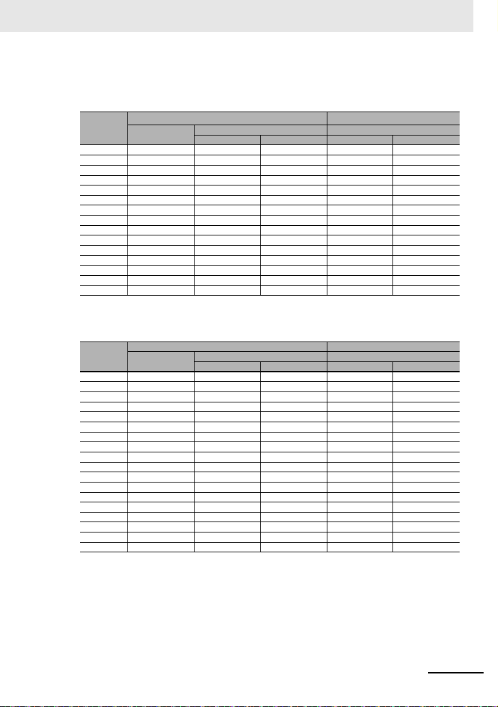
Compatibility Conditions of UL/CSA Standards
Required protection by Fuse and circuit-breakers
200V class
Model
3G3RX2
A2004 Class J or T 600 15 --- --A2007 Class J or T 600 30 --- --A2015 Class J or T 600 40 --- --A2022 Class J or T 600 40 --- --A2037 Class J or T 600 50 --- --A2055 Class J or T 600 100 --- --A2075 Class J or T 600 150 --- --A2110 Class J or T 600 150 --- --A2150 Class J or T 600 150 --- --A2185 Class J or T 600 200 --- --A2220 Class J or T 600 200 --- --A2300 Class J or T 600 300 --- --A2370 Class J or T 600 300 --- --A2450 Class J or T 600 400 --- --A2550 Class J or T 600 500 --- ---
Type
400V class
Model
3G3RX2
A4007 Class J or T 600 15 --- --A4015 Class J or T 600 20 --- --A4022 Class J or T 600 30 --- --A4037 Class J or T 600 30 --- --A4055 Class J or T 600 75 --- --A4075 Class J or T 600 75 --- --A4110 Class J or T 600 75 --- --A4150 Class J or T 600 100 --- --A4185 Class J or T 600 100 --- --A4220 Class J or T 600 100 --- --A4300 Class J or T 600 200 --- --A4370 Class J or T 600 200 --- --A4450 Class J or T 600 200 --- --A4550 Class J or T 600 250 --- --B4750 Class J or T 600 300 --- ---
B4900 Class J or T 600 400 --- --B411K Cla ss J or T 600 500 --- --B413K Class J or T 600 500 --- ---
Type
Fuse Circuit Breaker
Maximum Rating Maximum Rating
Voltage (V) Current (A) Vo ltage (V) Current (A)
Fuse Circuit Breaker
Maximum Rating Maximum Rating
Voltage (V) Current (A) Vo ltage (V) Current (A)
41
Page 86

Korean Radio Regulation (KC)
یࡈ߇ΰח
ࢇЕ߶הࡈˁ߾۰یࡈଟּࢶࡳԻࢶଢ۽ૡɼձ؇ࡵԻ۰
ɼࢽࡈˁ߾۰یࡈଜЕˁࡉࢷળɾۺࢂࡉԮɼݡТЬ
Korean Radio Regulation (KC)
Guide for Users
This equipment has been evaluated for conformity in a commercial environment.
When used in a residential environment, it may cause radio interference.
42
Page 87

Page 88

 Loading...