

Omron 3G3MX2-AB002-V1, 3G3MX2-AB007-V1, 3G3MX2-AB015-V1, 3G3MX2-AB004-V1, 3G3MX2-A2002-V1 Instruction Manual
...Page 1
形
3G3MX2-A□-V1
多機能型小型インバータ
取扱説明書
このたびは、インバータ 形 3G3MX2 シリーズ V1 タイプをお買い求
めいただきまして、誠にありがとうございます。
この製品を安全に正しくご使用いただくために、お使いになる前に、
この取扱説明書と安全上のご注意および下記のマニュアルを熟読し、
機器の知識、安全上の情報、注意事項のすべてについて習熟してから
ご使用ください。また、お読みになったあとも、いつも手元において
ご使用ください。
マニュアル番号マニュアル名称
3G3MX2 シリーズ V1 タイプ
ユーザーズマニュアル
オムロン株式会社
©OMRON Corporation 2012 All Rights Reserved.
安全上のご注意
■安全に使用していただくための 表 示と意 味について
この取扱説明書では、多機能型小型インバータ形 3G3MX2 を安
全にご使用いただくために注意事項を次のような表示と記号で示
しています。
ここで示した注意事項は、安全に関する重大な内容を記載してい
ます。必ず守ってください。
■警告表示の意味
取り扱いを誤った場合に、危険な状況が起こりえて、
危険
注意
死亡または重傷を受ける可能性が想定される場合、
および深刻な物的損害の発生が想定される場合。
取り扱いを誤った場合に、危険な状況が起こりえて、
中程度の傷害や軽傷を受ける可能性が想定される場合
および物的損害のみの発生が想定される場合。
■警告表示
危 険
万一の場合、感電による重度の傷害が起こるおそれがあります。
入力電源
万一の場合、感電による重度の傷害が起こるおそれがあります。
配線作業は、電気工事の専門家が行ってください。
万一の場合、感電による重度の傷害が起こるおそれがあります。
配線変更、スライドスイッチの変更、オペレータやオプション類の脱
着
万一の場合、感電・発火による重度の傷害が起こるおそれがあります。
接地端子は必ずアースしてください。
(
万一の場合、感電による重度の傷害が起こるおそれがあります。
通電中および電源遮断後
ください。
万一の場合、感電による重度の傷害が起こるおそれがあります。
濡れた手でオペレータ、スイッチ類を操作しないでください。
万一の場合、感電による重度の傷害が起こるおそれがあります。
緊急遮断入力機能が働いた状態になっても、主電源が遮断されたわけ
ではありません。製品の確認は、インバータの入力電源を
てから行ってください。
やけどのおそれがあります。
通電中や電源遮断後のしばらくの間は、インバータの冷却フィン、制
動抵抗器、モータなどは高温になる場合がありますので触れないでく
ださい。
OFF を確認してから正しく配線してください。
は
インバータの入力電源を OFFにしてから行ってください。
200V 級:D 種接地、400V級:C 種接地)
10 分以内は端子台カバーを外さないで
SBCE-376
2272253-5D
NT328C
OFF にし
注 意
軽度の発火、発熱、機器破損がまれに起こるおそれがあります。
端子(
+1、P/+2、N/-)に抵抗器を直接接続しないでください。
軽度の傷害がまれに起こるおそれがあります。
安全を確保するための停止装置を設置してください。
※保持ブレーキは安全を確保するための停止装置ではありません。
制動抵抗器や回生制動ユニットの発熱により、中程度のやけどがまれ
に起こるおそれがあります。
必ず指定された制動抵抗器や回生制動ユニットを使用し、制動抵抗器
を使用する場合には、抵抗器の温度を監視するサーマルリレーを設置
してください。また、制動抵抗器や回生制動ユニットの異常過熱時に
インバータの電源を
製品内部には高電圧部分があり、短絡させると製品の破損や物的損害
がまれに起こるおそれがあります。設置や配線時には切り粉やリード
線くずなどの金属物が製品内部に入らないようにカバーをつけるなど
の処置を行ってください。
負荷の短絡により物的損害がまれに起こるおそれがあります。
インバータの電源側にはインバータ容量に応じた配線用遮断機
(
MCCB
)を設置するなどの安全対策を施してください。
けがのおそれがあります。
分解や修理、改造は行わないでください。
安全上の要点
■設置・保管
下記環境下での保管および使用は避けてください。
・日光が直接当たる場所
・周囲温度が仕様を超える場所
・相対湿度が仕様を超える場所
・温度の変化が急激で結露するような場所
・腐食性ガス、可燃性ガスのある場所
・可燃物またはその近くの場所
・ちり、ほこり、塩分、鉄粉が多い場所
・水、油、薬品などの飛まつがかかる場所
・本体に直接振動や衝撃が伝わる場所
■輸送・設置・配線
・部品の故障、製品故障の原因となります。強い衝撃を与えたり、落下
させたりしないでください。
・運搬時は、フロントカバー・端子台カバーを持たずに冷却フィンを持
ってください。
・インバータの入力電源定格電圧と交流電源の電圧が一致していること
を確認してください。
・製品が破損しますので、制御入出力端子に交流電源を接続しないでくだ
さい。
・端子台のねじは確実に締め付けてください。また、配線は本体を据え
付けてから行ってください。
・本製品の出力
ください。
・次のような場所で使用する際は、遮断対策を十分に行ってください。
機器破損の原因となります。
静電気などによるノイズが発生する場所
強い磁界が生じる場所
電源線が近くを通る場所
・立ち上げ時、調整時、メンテナンス時、交換時にパラメータを誤って
設定すると予期せぬ動作が起きるおそれがあります。十分な確認を行
ったあと、運転に移行してください。
・
DriveProgramming を使用する場合は、プログラムデータが正常に
ダウンロードできたことを確認してから動作を開始してください。
■運転・調整
・本製品は低速から高速までの設定ができますので、使用するモータ設
備の許容範囲を十分に確認したあとで運転を行ってください。
・保持ブレーキが必要な場合は、別に用意してください。
・多機能出力が出力中に、
態を保持したまま
策を施してください。
・インバータの電源を
起電力が発生し、感電する危険性があります。
まで、インバータの端子台カバーを外さないでください。
・運転信号を入れたままアラームリセットを行うと突然始動しますので、
運転信号が切れていることを確認してからアラームリセットを行って
ください。
■保守・点検
・保守や点検、部品交換を行う際は、安全を確保したあとで行ってくださ
い。
・コンデンサの寿命は周囲温度に影響されます。ユーザーズマニュアル
に記載されている製品寿命カーブをご覧ください。コンデンサが寿命
に達し、製品として機能を果たさなくなった場合には、本体の交換が
必要となります。
(U, V, W) に三相誘導モータ以外の負荷を接続しないで
OFF するシーケンスを組んでください。
DriveProgramming が停止すると、出力状
になりますので、周辺機器を停止させるなど安全対
OFF しても、PM モータが回転している間は逆
PM モータが停止する
使用上の注意
■取り付け
・取付方向は縦長方向で壁取り付けとしてください。
また、取り付け壁の材質は金属板などの不燃材としてください。
■再始動選択機能
・再始動選択機能 (b001, b008) を使用すると、アラーム停止時に突然
始動しますので、近寄らないでください。
■瞬停・不足電圧減速停止機能
・瞬停・不足電圧減速停止機能選択 (b050) で再始動を選択した場合、
電源復帰後に突然再始動しますので注意してください。
■運転停止指令
・オペレータのストップボタンは機能設定したときだけ有効ですので、
緊急停止スイッチは別に用意してください。
・通電中に信号チェックを行い、誤って制御入力端子に電圧が印加され
るとモータが突然動き出すことがあります。信号チェックを行う際は
安全を確かめて行ってください。
■モータ過負荷保護
・モータ過負荷保護のために、電子サーマルレベル (b012/b212) や
PM モータ定格電流 (H105) に、ご使用のモータの定格電流を必ず設
定してください。
■保守・点検
・インバータは多数の部品で構成されており、これらの部品が正常に動
作することによって本来の機能を発揮します。電子部品の中には、使
用条件によっては保守が必要なものがあります。長期間にわたってイ
ンバータを正常に動作させるためには、これらの部品の耐用年数に合
わせた定期点検、部品交換が必要です。
(
JEMA 発行『汎用インバータの定期点検のお勧め』から引用)
■製品の廃棄
・本製品を破棄する際は、条例などの規則に従ってください。
UL対応に関するご注意
UL ガイドラインに適合するために必要な、インバータの設置手順につい
て記載します。
適合規格:
・形 3G3MX2-A2001-V1, -A2002-V1, -A2004-V1, -A2007-V1,
-AB015-V1, -AB022-V1, -A4004-V1, -A4007-V1, -A4015-V1,
-A4022-V1, -A4030-V1
ださい。
・形
-A2015-V1, -A2022-V1, -A2037-V1,-A2055-V1, -A2075-V1,
-A2110-V1, -A2150-V1, -A4040-V1, -A4055-V1, -A4075-V1,
-A4110-V1, -A41
さい。
・本インバータは、電流実効値が
240V、480V の回路に適合しています。
・本インバータは、
いるかまたは、電流実効値が 100kA 以上の遮断定格をもつブレーカで
保護されている、最大電圧 240V、480V の回路に適合しています。
・本インバータは、汚染度
・本インバータの使用周囲温度は、最大
・モータ保護(電子サーマル)は、定格負荷電流の
・インバータに搭載されている短絡保護は、分岐回路の保護をするわけで
はありません。
た
・モータの加熱保護機能は、本製品にはありません
UL508C、 CSA C22.2 No.14-5
には、UL 認定の 60/75℃の銅電線をご使用く
3G3MX2-AB001-V1, -AB002-V1, -AB004-V1, -AB007-V1,
50-V1
には、UL 認定の 75℃の銅電線をご使用くだ
100kA 以下に制限されている最大電圧
CC,G,J または R クラスの UL ヒューズで保護されて
2 の環境に設置してください。
50℃としてください。
150% で動作します。
National Electric Code や、他の相当する規格に基づい
分岐回路の保護回路をご使用ください。
。
■主回路端子台のねじサイズ、締め付けトルク、適用電線サイズ
形 式 ねじサイズ
3G3MX2-AB001-V1, 3G3MX2-AB002-V1,3G3MX2-AB004-V1
3G3MX2-AB007-V1
3G3MX2-AB015-V1, 3G3MX2-AB022-V1
3G3MX2-A2001-V1, 3G3MX2-A2002-V1, 3G3MX2-A2004-V1,
3G3MX2-A2007-V1
3G3MX2-A2015-V1
3G3MX2-A2022-V1
3G3MX2-A2037-V1
3G3MX2-A2055-V1, 3G3MX2-A2075-V1
3G3MX2-A2110-V1
3G3MX2-A2150-V1
3G3MX2-A4004-V1, 3G3MX2-A4007-V1, 3G3MX2-A4015-V1
3G3MX2-A4022-V1, 3G3MX2-A4030-V1
3G3MX2-A4040-V1
3G3MX2-A4055-V1, 3G3MX2-A4075-V1
3G3MX2-A4110-V1, 3G3MX2-A4150-V1
締め付けトルク
[N・m]
M3.5 1.0
M4 1.4 AWG12(3.3mm2)
M4 1.4 AWG10(5.3mm2)
M3.5 1.0 AWG16(1.3mm
M4 1.4 AWG14(2.1mm2)
M4 1.4 AWG12(3.3mm2)
M4 1.4 AWG10(5.3mm
M5 3.0 AWG6(13mm
M6
M8
M4 1.4 AWG16(1.3mm
M4 1.4 AWG14(2.1mm
3.9 〜 5.1 AWG4(21mm
5.9 〜 8.8 AWG2(34mm
適用電線サイズ
AWG16(1.3mm
AWG12(3.3mm
AWG10(5.3mm
AWG6(13mm
2
2
2
2
)
2
)
2
)
2
2
2
2
2
)M6 3.9 〜 5.1
■ヒューズ
UL 規格に対応される場合は、下表に示す電流定格をもつ AC600V 定格
の
UL リステッド・カートリッジ・ノンリニューワブルヒューズを電源
側に使用してください。
インバータ形式 タイプ 定格
3G3MX2-AB001-V1, 3G3MX2-AB002-V1,
3G3MX2-AB004-V1
3G3MX2-AB007-V1
3G3MX2-AB015-V1
3G3MX2-AB022-V1
3G3MX2-A2001-V1, 3G3MX2-A2002-V1,
3G3MX2-A2004-V1,
3G3MX2-A2007-V1, 3G3MX2-A2015-V1
3G3MX2-A2022-V1
3G3MX2-A2037-V1
3G3MX2-A2055-V1, 3G3MX2-A2075-V1
3G3MX2-A2110-V1, 3G3MX2-A2150-V1
3G3MX2-A4004-V1, 3G3MX2-A4007-V1,
3G3MX2-A4015-V1, 3G3MX2-A4022-V1
3G3MX2-A4030-V1, 3G3MX2-A4040-V1
3G3MX2-A4055-V1, 3G3MX2-A4075-V1
3G3MX2-A4110-V1, 3G3MX2-A4150-V1
Class J
Class J
Class J
10A, AIC 200kA
20A, AIC 200kA
30A, AIC 200kA
30A, AIC 200kA
10A, AIC 200kA
15A, AIC 200kA
20A, AIC 200kA
30A, AIC 200kA
60A, AIC 200kA
80A, AIC 200kA
10A, AIC 200kA
15A, AIC 200kA
30A, AIC 200kA
50A, AIC 200kA
EU指令対応に関して
・EMC 指令 (EN61800-3) に適合するために、オプションの EMC 用ノイ
ズフィルタを使用してください。
・
EMC 指令に適合するための、接地・ケーブル選定・その他の条件つい
ては、該当するユーザーズマニュアルを参照してください。
■製造者およびEU代理人
製造者 :
OMRON Corporation
京都市下京区塩小路堀川東入
EU 代理人:
Omron Europe B.V.
Wegalaan 67-69, NL-2132 JD Hoofddorp, The Netherlands
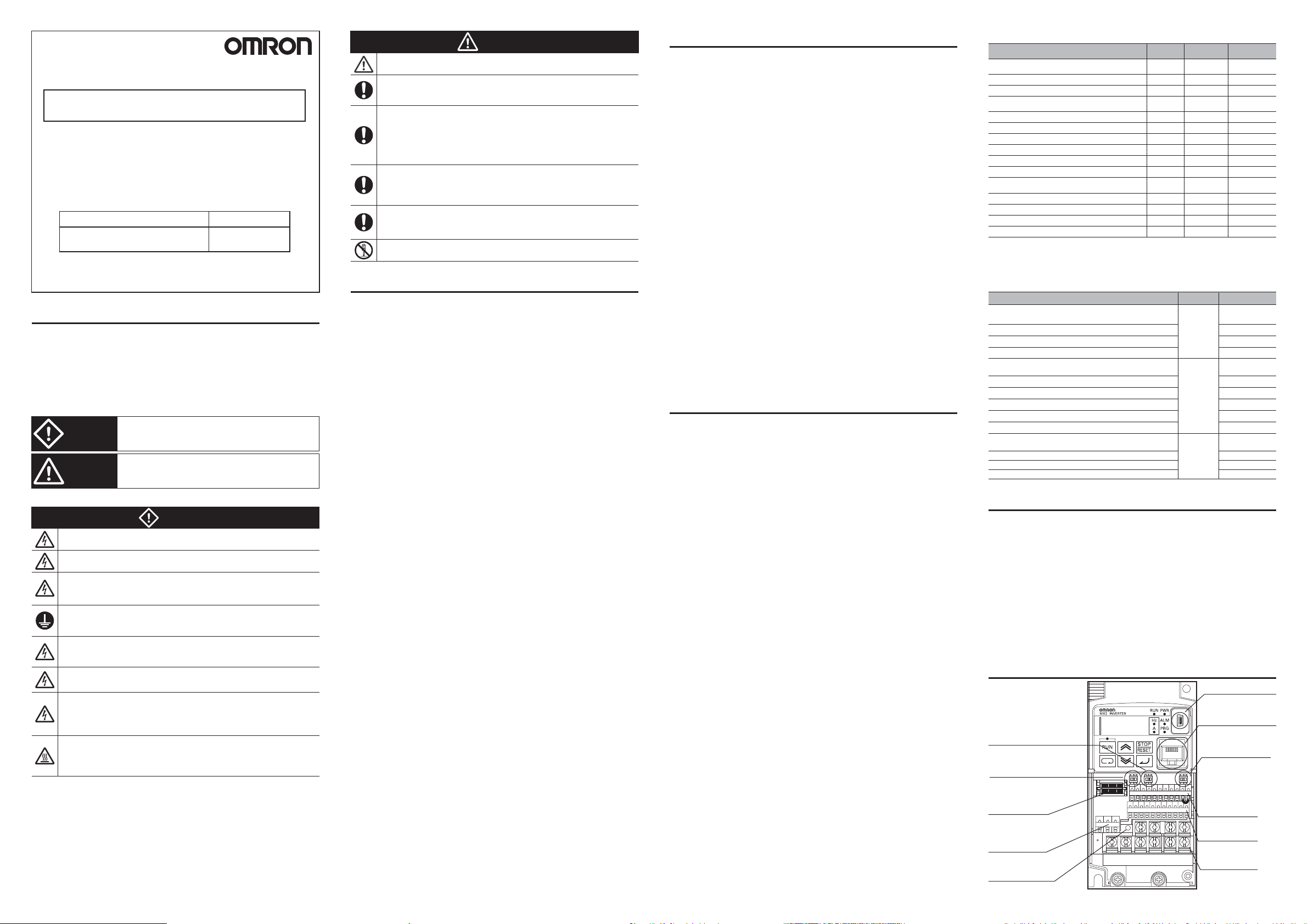
各部の名称
USBコネクタ(mini-B)
オペレータ接続
(RJ45)
コネクタ
セーフティ機能切替スイッチ
無効 ⇔ 有効
Modbus通信
終端抵抗切替スイッチ
OFF ⇔ ON
オプション
取付コネクタ
多機能リレー出力
端子台
LED
チャージ
EDM機能切替スイッチ
⇔ EDM
P1
制御回路端子台
制御回路端子台B
主回路端子台
A
)
)
)
)
)
)M4 1.4
)M5 3.0
Page 2
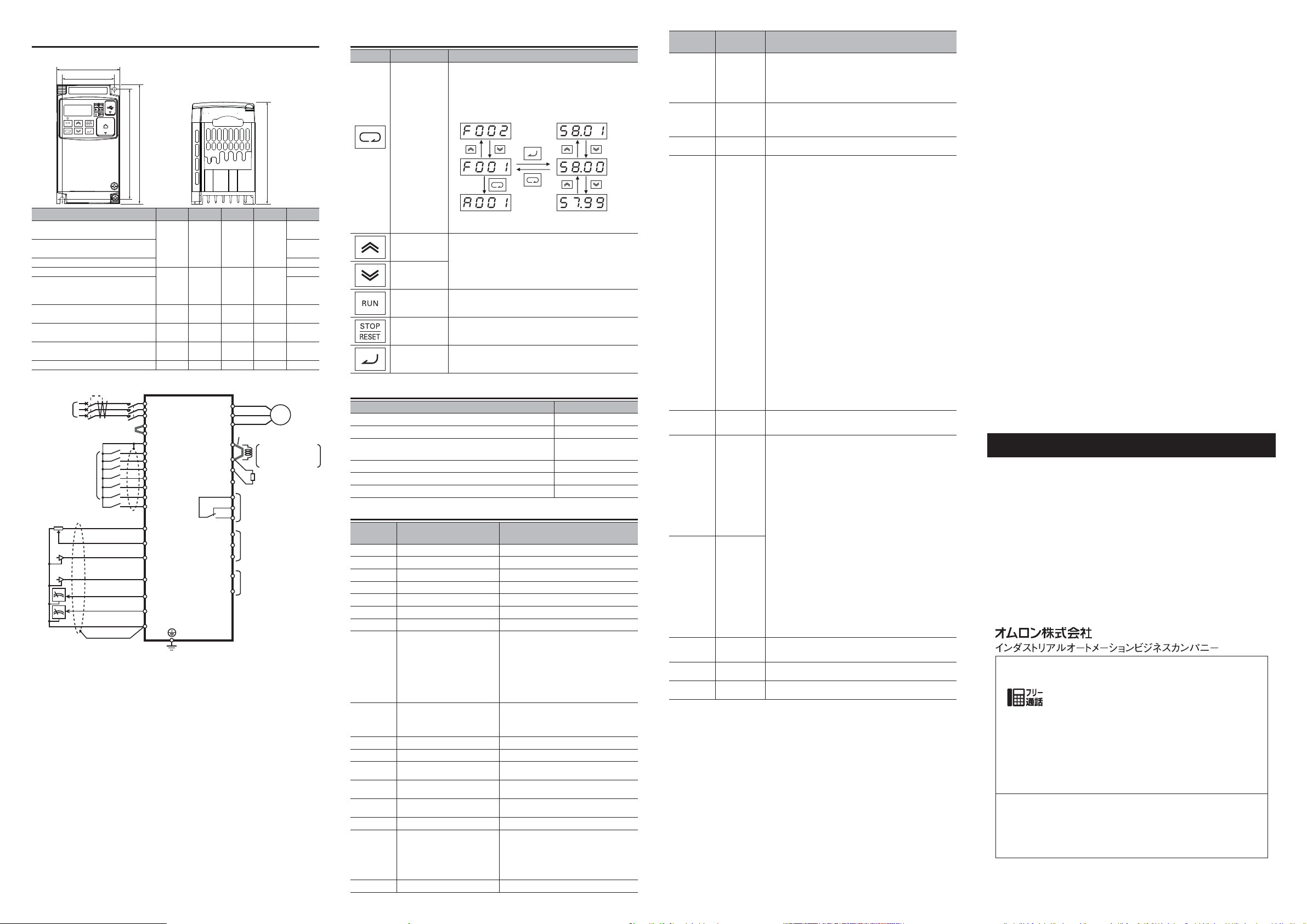
取り付けと配線
■外形寸法
3G3MX2-
AB001-V1, AB002-V1
A2001-V1, A2002-V1
AB004-V1
A2004-V1
A2007-V1
A4004-V1
AB007-V1, AB015-V1, AB022-V1
A2015-V1, A2022-V1, A4007-V1
A4015-V1, A4022-V1, A4030-V1
A2037-V1
A4040-V1
A2055-V1, A2075-V1
A4055-V1, A4075-V1
A2110-V1
A4110-V1, A4150-V1
A2150-V1 175336
■標準接続図
単相/
三相電源
多機能入力(
1〜2 kΩ
W
W1
H
H1
WW1H H1 D
68 56 128 118
108 96 128 118
140 128 128 118 170.5
140 122 260 248 155
180 160 296 284 175
350192220
ELB
*3
7接点)
(
アナログ電圧入力
0〜10V(10ビット)
アナログ電流入力
4〜20mA(10ビット)
(32kHz Max.)
アナログ電圧出力
0〜10V(10ビット)
0〜10V(32kHz Max.
*1. 単相 200V モデルでは、L1,N 端子に接続してください。
*2. リレー出力の工場出荷時設定は、MA が b 接点、MB が a 接点です。
*3. 制御端子の配線が複数のインバータにまたがる場合は、マニュアルに記載している
回り込み電流の対策を実施してください。
短絡バー
DC10V電源
10mA Max.)
パルス列入力
5〜24VDC
パルス列出力
MC
)
R/L1(L1)
S/L2
T/L3(N)
P24
PSC
SC
S7/EB
S6
S5/TH
S4/GS2
S3/GS1
S2
S1
FS
FV
FI
RP
AM
MP
SC
*1
*1
D種接地(200V級)
C種接地(400V級)
U/T1
V/T2
W/T3
P/+2
MC
MA
MB
P1/EDM
RS+
RS-
短絡バー
+1
RB
N/-
P2
PC
(
直流リアクトル
直流リアクトル を接 続す る
場合は短絡バーを取り外
してください
制動抵抗器
多機能リレー 出力
多機能出力(2端子)
シリア ル通 信ポ ート
RS485/Modbus)
キーの 説明
名 称 内 容
・パラメータ No.表示時は、次機能モードへ移行しま
す。
・パラメータデータ表示時は、変更途中の設定データ
をキャンセルしてパラメータ
す。
No. の表示に移行しま
■状態遷移
モードキー
D
※モードキーを 3秒以上押し続けると、d001 にジャ
109
122.5
145.5
143.5
170.5
インクリメント
キー
デクリメント
キー
RUN キー
STOP/RESET
キー
エンターキー
ンプします。
設定値やパラメータ、コマンドの変更を行います。
運転を開始します。正転・逆転は、F004 の設定に
従います。
運転を停止します。異常発生時はリセットキーに
なります。
・パラメータ No.から設定データ表示に移行します。
・設定データを確定し記憶します。
[mm]
関連マニュアル
M
モータ
マニュアル名称
CX-Drive オペレーションマニュアル
DriveProgramming ユーザーズマニュアル
回生制動ユニット
形
3G3AX-RBU□□ユーザーズマニュアル
EtherCAT 通信ユニットユーザーズマニュアル
CompoNet 通信ユニットユーザーズマニュアル
DeviceNet 通信ユニットユーザーズマニュアル
*2
マニュアル番号
SBCE-375
SBCE-369
SBCE-350
SBCE-361
SBCE-371
SBCE-370
パラメータ一覧
パラメータ
No.
d001
d002
d003
F001
F002
F003
F004
A001
A002
A003
A004
A019
A020
A021 ~ A035 多段速指令 1 〜 15
b012
b037
b082
機能名称 モニタまたはデータ範囲
出力周波数モニタ
出力電流モニタ
運転方向モニタ
出力周波数設定/モニタ 始動周波数
1 加速時間 0.00 〜 3600. [s]
第
1 減速時間 0.00 〜 3600. [s]
第
運転方向選択
1 周波数指令選択
第
1 運転指令選択
第
第
1 基底周波数 30.0 〜最高周波数 (A004) [Hz]
1 最高周波数 基底周波数 (A003) 〜 400.0 [Hz]
第
多段速選択
多段速指令
第 1 電子サーマルレベル
表示選択
始動周波数
0
0.00 〜 400.0 [Hz]
0.0 〜 655.3 [A]
F:正転 / o:停止 / r:逆転
(b082) 〜最高周波数 (A004) [Hz]
00:正転 / 01:逆転
00:オペレータ(ボリューム)
3G3AX-OP01 接続時に有効
形
01:制御回路端子台
02:オペレータ(F001)
03:ModBus 通信
04:オプション
06:パルス列周波数
07:DriveProgramming
10:周波数演算結果
01:制御回路端子台
02:オペレータ
:ModBus 通信
03
04:オプション
00:バイナリ(4 端子で 16 段可)
01:ビット(7 端子で 8 段可)
/
0.00,
始動周波数
0.00,
始動周波数
インバータ定格電流の
00
01:機能個別表示
02:ユーザ設定 +b037
03
04:ベーシック表示
05:モニタ表示のみ
(b082) 〜最高周波数 (A004)[Hz]
/
(b082) 〜最高周波数 (A004)[Hz]
20 〜 100% [A]
:全表示
:データコンペア表示
0.01 〜 9.99 [Hz]
パラメータ
No.
b084
b094
b180
C001 ~ C007
C011 ~ C017
C021 ~ C022
C026
C031, C032,
C036
H003
H004
機能名称 モニタまたはデータ範囲
00:初期化無効
01:異常モニタクリア
初期化範囲選択
初期化対象選択
初期化実行
多機能入力
S1 〜 S7 選択
多機能入力
S1 〜 S7
動作選択
多機能出力
P1, P2 選択
多機能
(MA, MB)
出力
機能選択
多機能リレー
出力接点選択
第
1 モータ
容量選択
第
1 モータ
極数選択
02:データ初期化
03:異常モニタクリア+データ初期化
04:異常モニタクリア+データ初期化+
DriveProgramming クリア
00:全データ
01:端子・通信以外全データ
02:U***登録機能だけ
03:U***登録機能以外
00:機能無効
01:初期化実行
00:FW(正転)/ 01:RV(逆転)/ 02:CF1(多段速設定
1)/ 03:CF2(多段速設定バイナリ 2)/ 04:CF3(多
バイナリ
段速設定バイナリ
06:JG(ジョギング)/ 07:DB(外部直流制動)/ 08:SET(第
2 制御)/ 09:2CH(2 段加減速)/ 11:FRS(フリーラン
ストップ)
動防止機能)/
ク)/
19:TH(外部サーミスタ、C005 だけ)/ 20:STA(3 ワイ
ヤ起動)/
逆)/
27:UP(遠隔操作増速)/ 28:DWN(遠隔操作減速)
29:UDC(遠隔データクリア)/ 31:OPE(強制オペ機能)
32:SF1(多段速設定ビット 1)/ 33:SF2(多段速設定ビッ
2)/ 34:SF3(多段速設定ビット 3)/ 35:SF4(多段速
ト
設定ビット
(多段速設定ビット 6)/ 38:SF7(多段速設定ビット 7)
39:OLR(過負荷制限切替)/ 40:TL(トルクリミット有効)
41:TRQ1(トルクリミット切替 1)/ 42:TRQ2(トルクリ
ミット切替
ンセル)/
周波数
ルク指令入力許可)/
62:MI1 〜 7(汎用入力 1〜 7)/ 65:AHD(アナログ指令保持)
66:CP1(位置指令選択 1)/ 67:CP2(位置指令選択 2)
68:CP3(位置指令選択 3)/ 69:ORL(原点復帰リミット信号)
70:ORG(原点復帰起動信号)/ 73:SPD(速度/位置切替)
77:GS1(セーフティ入力 1)/ 78:GS2(セーフティ入力
2)/ 81:485(インバータ通信起動)
82:PRG(DriveProgramming起動)/ 83:HLD(加減速停止)
84:ROK(運転許可信号)/ 85:EB(検出回転方向、C007
だけ)/ 86:DISP(表示固定)/ 91:PSET(現在位置プリ
セット)/
00: NO(a 接点)
01: NC(b 接点)
00:RUN(運転中信号)/ 01:FA1(定速到達時信号)
02:FA2(設定周波数以上到達信号)/ 03:OL(過負荷予告)
04:OD(PID 偏差過大)/ 05:AL(アラーム信号)
06:FA3(設定周波数だけ到達信号)/ 07:OTQ(オーバ/
アンダトルク信号)/
(トルク制限中)/ 11:RNT(RUN 時間オーバ)/ 12:ONT
(電源 ON 時間オーバ)/ 13:THM(サーマル警告)
19:BRK(ブレーキ開放)/ 20:BER(ブレーキ異常)
21:ZS(0Hz 検出信号)/ 22:DSE(速度偏差過大)
23:POK(位置決め完了)/ 24:FA4(設定周波数以上 2)
25:FA5(設定周波数だけ 2)/ 26:OL2(過負荷予告 2)
27:FVdc(アナログ FV 断線検出)/ 28:FIDc(アナログ FI
断線検出)/ 31:FBV(PID フィードバック比較信号)
32:NDc(通信断線検出)/ 33:LOG1(論理演算結果 1)
34:LOG2(論理演算結果 2)/ 35:LOG3(論理演算結果 3)
39:WAC(コンデンサ寿命予告信号)/ 40:WAF(冷却ファ
ン寿命予告信号)/
却フィン過熱予告)/
MO1 〜 3(汎用出力 1 〜 3)/ 50:IRDY(運転準備完了)
リレー
51:FWR(正転運転中信号)/ 52:RVR(逆転運転中信号)
53:MJA(重故障信号)/ 54:WCFV(ウインドウコンパレー
FV)/ 55:WCFI(ウインドウコンパレータ FI)
タ
58:FREF(周波数指令オペレータ)/ 59:REF
(運転指令オペレータ)/ 60:SETM(第 2 モータ選択中)
62:EDM(セーフティモニタ信号)/ 63:OPO(オプション)
no:NO(割り付けなし )
00:NO(MA が a 接点、MB が b 接点)
01:NC(MA が b 接点、MB が a 接点)
0.1 / 0.2 / 0.4 / 0.55 / 0.75 / 1.1 / 1.5 / 2.2 / 3.0 / 3.7 / 4.0 / 5.5 /
7.5 / 11.0 / 15.0 / 18.5 [kW]
3)/ 05:CF4(多段速設定バイナリ 4)
12:EXT(外部トリップ)/ 13:USP(復電再始
14:CS(商用切替)/ 15:SFT(ソフトロッ
16:FV/FI(アナログ入力切替)/ 18:RS(リセット)
21:STP(3 ワイヤ停止)/ 22:F/R(3 ワイヤ正
23:PID(PID 無効)/ 24:PIDC(PID積分リセット)
4)/ 36:SF5(多段速設定ビット 5)/ 37:SF6
2)/ 44:BOK(ブレーキ確認)/ 46:LAC(LAD キャ
47:PCLR(位置偏差クリア)/ 50:ADD(設定
A145 加算)/ 51:F-TM(強制端子台)/ 52:ATR(ト
53:KHC(積算電力クリア)/ 56 〜
no:NO(割り付けなし )
09:UV(不足電圧中信号)/ 10:TRQ
41:FR(起動接点信号)/ 42:OHF(冷
43:LOC(低電流信号)/ 44 〜 46:
2 〜 48[極](偶数極だけ設定可能)
ご承諾事項
当社商品は、一般工業製品向けの汎用品として設計製造されています。従いまして、
次に掲げる用途での使用を意図しておらず、お客様が当社商品をこれらの用途に使用
される際には、当社は当社商品に対して一切保証をいたしません。ただし、次に掲げる
用途であっても当社の意図した商品用途の場合や特別の合意がある場合は除きます。
(a)
高い安全性が必要とされる用途(例:原子力制御設備、燃焼設備、航空・宇宙設備、鉄道設備、
昇降設備、娯楽設備、医用機器、安全装置、その他生命・身体に危険が及びうる用途)
(b) 高い信頼性が必要な用途(例:ガス・水道・電気等の供給システム、24 時間
連続運転システム、決済システムほか権利・財産を取扱う用途など)
(
c) 厳しい条件または環境での用途(例:屋外に設置する設備、化学的汚染を被る
設備、電磁的妨害を被る設備、振動・衝撃を受ける設備など)
d) カタログ等に記載のない条件や環境での用途
(
* (a) から (d) に記載されている他、本カタログ等記載の商品は自動車(二輪車含む。以下同じ)
向けではありません。自動車に搭載する用途には利用しないで下さい。自動車搭載用商品に
ついては当社営業担当者にご相談ください。
* 上記は適合用途の条件の一部です。当社のベスト、総合カタログ、データシート等最新版の
カタログ、マニュアルに記載の保証・免責事項の内容をよく読んでご使用ください。
●製品に関するお問い合わせ先
お客様相談室
クイック オムロン
0120-919-066
携帯電話・PHS・IP電話などではご利用いただけませんので、下記の電話番号へおかけください 。
電話
055-982-5015
■営業時間:8:00〜21:00 ■営業日:365日
●FAXやWebページでもお問い合わせいただけます。
FAX055-982-5051/www.fa.omron.co.jp
●その他のお問い合わせ
納期・価格・サンプル・仕様書は貴社のお取引先、または貴社
担当オムロン販売員にご相談ください。
オムロン制御機器販売店やオムロン販売拠点は、Webページで
ご案内しています。
お断りなく仕様などを変更することがありますのでご了承ください。
(通話料がかかります)
2272253-5D
NT328C
Page 3

3G3MX2-A-V1
Multi-function Compact Inverter
INSTRUCTION MANUAL
Thank you for purchasing 3G3MX2 series type V1 Inverter.
To ensure the safe operation, please be sure to read the safety
precautions provided in this document along with all of the user
manuals for the inverter. Please be sure you are using the most
recent versions of the user manuals. Keep this instruction manual
and all of the manuals in a safe location and be sure that they are
readily available to the final user of the products.
Cat.No.Manual Name
3G3MX2 series type V1
User’s Manual
I585-E1
OMRON Corporation
©OMRON Corporation 2012 All Rights Reserved.
2272253-5D
NT328XC
Safety Precautions
Indications and Meanings of Safety Information
In this user’s Manual, the following precautions and signal words
are used to provide information to ensure the safe use of the
3G3MX2 Multi-function Compact Inverter.
The information provided here is vital to safety. Strictly observe
the precautions provided.
Meanings of Signal Words
Indicates a potentially hazardous situation which,
WARNING
CAUTION
Alert Symbols in this Document
if not avoided, will result in minor or moderate injury,
or may result in serious injury or death. Additionally
there may be significant property damage.
Indicates a potentially hazardous situation which,
if not avoided, may result in minor or moderate
injury or in property damage.
WARNING
Turn off the power supply and implement wiring correctly.
Not doing so may result in a serious injury due to an electric shock.
Wiring work must be carried out only by qualified personnel. Not
doing so may result in a serious injury due to an electric shock.
Do not change wiring and slide switches, put on or take off Operator
and optional devices, replace cooling fans while the input power is being
supplied. Doing so may result in a serious injury due to an electric shock.
Be sure to ground the unit. Not doing so may result in a serious injury
due to an electric shock or fire.
(200V class:type-D grounding, 400V class:type-C grounding)
Do not remove the front cover during the power supply and 10 minutes
after the power shutoff. Doing so may result in a serious injury due to
an electric shock.
Do not operate the Operator or switches with wet hands.
Doing so may result in a serious injury due to an electric shock.
Inspection of the Inverter must be conducted after the power supply has
been turned off. Not doing so may result in a serious injury due to an
electric shock.
The main power supply is not necessarily shut off even if the emergency
shut off function is activated.
Do not touch the Inverter fins, braking resistors and the motor, which
become too hot during the power supply and for some time after the
power shutoff. Doing so may result in a burn.
CAUTION
Do not connect resistors to the terminals (+1, P/+2, N/-) directly.
Doing so might result in a small-scale fire, heat generation or damage
to the unit.
Install a stop motion device to ensure safety. Not doing so might result
in a minor injury. (A holding brake is not a stop motion device designed
to ensure safety.)
Be sure to use a specified type of braking resistor / regenerative
braking unit. In case of a braking resistor, install a thermal relay that
monitors the temperature of the resistor. Not doing so might result in a
moderate burn due to the heat generated in the braking resistor /
regenerative braking unit. Configure a sequence that enables the
Inverter power to turn off when unusual overheating is detected in the
braking resistor / regenerative braking unit.
The Inverter has high voltage parts inside which, if short-circuited,
might cause damage to itself or other property. Place covers on the
openings or take other precautions to make sure that no metal objects
such as cutting bits or lead wire scraps go inside when installing and
wiring.
Take safety precautions such as setting up a molded-case circut
breaker(MCCB) that matches the Inverter capacity on the power
supply side. Not doing so might result in damage to property due to
the short circuit of the load.
Do not dismantle, repair or modify the product.
Doing so may result in an injury.
Precautions for Safe Use
Installation and Storage
Do not store or use the product in the following places.
x
Locations subject to direct sunlight.
x
Locations subject to ambient temperature exceeding the specifications.
x
Locations subject to relative humidity exceeding the specifications.
x
Locations subject to condensation due to severe temperature fluctuations.
x
Locations subject to corrosive or flammable gases.
x
Locations subject to exposure to combustibles.
x
Locations subject to dust (especially iron dust) or salts.
x
Locations subject to exposure to water, oil, or chemicals.
x
Locations subject to shock or vibration.
Transporting, Installation and Wiring
x
Do not drop or apply a strong impact on the product.
Doing so may result in damaged parts or malfunction.
x
Do not hold by the front cover and terminal cover, but hold by the fins
during transportation.
x
Confirm that the rated input voltage of the Inverter is the same as AC
power supply voltage.
x
Do not connect an AC power supply voltage to the control input / output
terminals. Doing so may result in damage to the product.
x
Be sure to tighten the screws on the terminal block securely. Wiring work
must be done after installing the unit body.
x
Do not connect any load other than a three-phase inductive motor to the
U, V and W output terminals.
x
Take sufficient shielding measures when using the product in the following
locations. Not doing so may result in damage to the product.
Locations subject to static electricity or other forms of noise.
Locations subject to strong magnetic fields.
Locations close to power lines.
x
If a parameter is set incorrectly when starting up, adjusting, maintaining,
or replacing, an unexpected operation may occur. Perform the operation
after enough confirmation.
x
When using DriveProgramming, confirm that the program data is
downloaded normally before starting operation.
Operation and Adjustment
x
Be sure to confirm the permissible range of motors and machines before
operation because the inverter speed can be changed easily from low to
high.
x
Provide a separate holding brake if necessary.
x
If the DriveProgramming stops during multi-function output, the output
status is held. Take safety precautions such as stopping peripheral
devices.
x
Even if the inverter power supply is turned off, the counter-electromotive
force occurs while the PM motor rotates, which may result in electric shock.
Do not remove the terminal block cover of the inverter until the PM motor
stops.
x
Be sure to confirm the RUN signal is turned off before resetting the alarm
because the machine may abruptly start.
Maintenance and Inspection
x
Be sure to confirm safety before conducting maintenance,
inspection or parts replacement.
x
The capacitor service life is influenced by the ambient temperature.
Refer to "Product Life Curve" described in the User’s manual. When a
capacitor reaches the end of its service life and does not work as the
product, you need to replace the capacitor.
Precautions for Correct Use
Installation
x
Mount the product vertically on a wall with the product’ s longer sides
upright.
The material of the wall has to be nonflammable such as a metal plate.
Restart Selection Function
x
Do not come close to the machine when using the restart selection function
(b001, b008)
because the machine may abruptly start when stopped by
an alarm.
Deceleration Stop Function
x
Do not come close to the machine when selecting reset in the deceleration
stop function (b050) because the machine may abruptly start after the
power is turned on.
Operation Stop Command
x
Provide a separate emergency stop switch because the STOP Key on the
Operator is valid only when function settings are performed.
x
When checking a signal during the power supply and the voltage is
erroneously applied to the control input terminals, the motor may start
abruptly. Be sure to confirm safety before checking a signal.
Motor Overload Protection
x
For the motor overload protection, be sure to set the rated current of your
motor to the Electronic Thermal Level (b012/b212) and PM Motor Rated
Current (H105).
Maintenance and Parts Replacement
x
Inverters contain components and will operate properly only when each
component operates normally. Some of the electrical components require
maintenance depending on application conditions.
Periodic inspection and replacement are necessary to ensure proper
long-term operation of Inverters. (Quoted from The Recommendation for
Periodic Maintenance of a General-purpose Inverter published by JEMA.)
Product Disposal
x
Comply with the local ordinance and regulations when disposing of the
product.
UL Cautions
The warnings and instructions in this section summarizes the procedures
necessary to ensure an inverter installation complies with Underwriters
Laboratories guidelines.
x
Use 60/75°C Cu wire only.
(For models:3G3MX2-A2001-V1, -A2002-V1, -A2004-V1, -A2007-V1,
-AB015-V1, -AB022-V1, -A4004-V1, -A4007-V1, -A4015-V1, -A4022-V1,
and -A4030-V1)
x
Use 75°C Cu wire only.
(For models:3G3MX2-AB001-V1, -AB002-V1, -AB004-V1, -AB007-V1,
-A2015-V1, -A2022-V1, -A2037-V1, -A2055-V1, -A2075-V1, -A2110-V1,
-A2150-V1, -A4040-V1, -A4055-V1, -A4075-V1, -A4110-V1 and
-A4150-V1)
x
Suitable for use on a circuit capable of delivering not more than 100,000
rms Symmetrical Amperes, 240 or 480 Volts Maximum.
x
When Protected by CC, G, J, or R Class Fuses, or when Protected By A
Circuit Breaker Having An Interrupting Rating Not Less Than 100,000
rms Symmetrical Amperes, 240 or 480 Volts Maximum.
x
Install device in pollution degree 2 environment.
x
Maximum surrounding air temperature rating of 50°C
x
Solid State motor overload protection reacts with max. 150 % of FLA.
x
Integral solid state short circuit protection does not provide branch circuit
protection. Branch circuit protection must be provided in accordance with
the National Electric Code and any additional local codes.
x
Motor over temperature protection is not provided by the drive.
AVERTISSEMENT: ne retirez pas le capot avant pendant l’alimentation
et 10 minutes après l’arrêt de l’alimentation. Cela peut entraîner de
grave blessure due à un choc électrique.
Terminal symbols and Screw size
Model No.
3G3MX2-AB001-V1, 3G3MX2-AB002-V1, 3G3MX2-AB004-V1
3G3MX2-AB007-V1
3G3MX2-AB015-V1, 3G3MX2-AB022-V1
3G3MX2-A2001-V1, 3G3MX2-A2002-V1, 3G3MX2-A2004-V1,
3G3MX2-A2007-V1
3G3MX2-A2015-V1
3G3MX2-A2022-V1
3G3MX2-A2037-V1
3G3MX2-A2055-V1, 3G3MX2-A2075-V1
3G3MX2-A2110-V1
3G3MX2-A2150-V1
3G3MX2-A4004-V1, 3G3MX2-A4007-V1, 3G3MX2-A4015-V1
3G3MX2-A4022-V1, 3G3MX2-A4030-V1
3G3MX2-A4040-V1
3G3MX2-A4055-V1, 3G3MX2-A4075-V1
3G3MX2-A4110-V1, 3G3MX2-A4150-V1
Fuse Size
The Inverter shall be connected with a UL Listed Cartridge Nonrenewable
fuse, rated 600Vac with the current ratings as shown in the table below.
Model No. Type Rating
3G3MX2-AB001-V1, 3G3MX2-AB002-V1,
3G3MX2-AB004-V1
3G3MX2-AB007-V1
3G3MX2-AB015-V1
3G3MX2-AB022-V1
3G3MX2-A2001-V1, 3G3MX2-A2002-V1,
3G3MX2-A2004-V1
3G3MX2-A2007-V1, 3G3MX2-A2015-V1
3G3MX2-A2022-V1
3G3MX2-A2037-V1
3G3MX2-A2055-V1, 3G3MX2-A2075-V1
3G3MX2-A2110-V1, 3G3MX2-A2150-V1
3G3MX2-A4004-V1, 3G3MX2-A4007-V1,
3G3MX2-A4015-V1, 3G3MX2-A4022-V1
3G3MX2-A4030-V1, 3G3MX2-A4040-V1
3G3MX2-A4055-V1, 3G3MX2-A4075-V1
3G3MX2-A4110-V1, 3G3MX2-A4150-V1
Conformance to EU Directives
x
It is necessary to use optional EMC filter to comply with EMC directive
(EN61800-3).
x
For earthing, selection of cable, and any other conditions for EMC
compliance, please refer to the User’s manual for installation.
OMRON Corporation
Shiokoji Horikawa, Shimogyo-ku, Kyoto, 600-8530, Japan
Omron Europe B.V.
Wegalaan 67-69, NL-2132 JD Hoofddorp, The Netherlands
Safety
For use of the drive as a safety device, to meet the requirements of the
ISO13849-1, please refer to user’s manual.
For KC Marking Only
ἽGὤὤஂ㛹ⱨ㟝Gⵝ㋕䋩㐔ὤ㣄㣠ஃG
㢨Gὤὤ⏈G㛹ⱨ㟝OἽPG㤸㣄䑀㤵䚝ὤὤ⦐㉐G䑄⬘㣄G❄⏈G㇠㟝㣄⏈G㢨G
㥄㡸G㨰㢌䚌㐐ὤGⵈ⢰⮤SGᴴ㥉㞬㢌G㫴㜡㜄㉐G㇠㟝䚌⏈Gᶷ㡸G⯝㤵㡰⦐G
䚝⏼␘U
Screw
Required
Size
Torque(N·m)
M3.5 1.0
M4 1.4 AWG12(3.3mm2)
M4 1.4 AWG10(5.3mm2)
M3.5 1.0 AWG16(1.3mm
M4 1.4 AWG14(2.1mm2)
M4 1.4 AWG12(3.3mm2)
M4 1.4 AWG10(5.3mm
M5 3.0 AWG6(13mm
M6 3.9 to 5.1 AWG4(21mm
M8 5.9 to 8.8 AWG2(34mm
M4 1.4 AWG16(1.3mm
M4 1.4 AWG14(2.1mm
Class J
Class J
Class J
Wire Range
AWG16(1.3mm
AWG12(3.3mm
AWG10(5.3mm
AWG6(13mm
10A, AIC 200kA
20A, AIC 200kA
30A, AIC 200kA
30A, AIC 200kA
10A, AIC 200kA
15A, AIC 200kA
20A, AIC 200kA
30A, AIC 200kA
60A, AIC 200kA
80A, AIC 200kA
10A, AIC 200kA
15A, AIC 200kA
30A, AIC 200kA
50A, AIC 200kA
2
)
2
)
2
)
2
)
2
)
2
)
2
)
2
)
2
)M4 1.4
2
)M5 3.0
2
)M6 3.9 to 5.1
Page 4

Names of Parts
USB connector (mini-B)
Connector for
Digital Operator (RJ45)
Safety function selector switch
Modbus Communication
Termination resistor selector switch
Connector for
option
Multi-function contact
terminal block
CHARGE indicator
EDM function
selector switch
Control circuit
terminal block A
Control circuit
terminal block B
Main circuit
terminal block
Installation and Wiring
Dimensions
3G3MX2-
AB001-V1, AB002-V1
A2001-V1, A2002-V1
AB004-V1
A2004-V1
A2007-V1
A4004-V1
AB007-V1, AB015-V1, AB022-V1
A2015-V1, A2022-V1, A4007-V1
A4015-V1, A4022-V1, A4030-V1
A2037-V1
A4040-V1
A2055-V1, A2075-V1
A4055-V1, A4075-V1
A2110-V1
A4110-V1, A4150-V1
A2150-V1 175336
W1
W
H
H1
WW1H H1 D
68 56 128 118
108 96 128 118
140 128 128 118 170.5
140 122 260 248 155
180 160 296 284 175
350192220
Standard Connection Diagram
Single-phase/
3-phase
power supply
Multi-function input
(7 contacts)
In case two or more
inverters are connected
to common I/O wiring,
special care to be taken
to avoid closed loop
circuit. Please refer to
user’s manual.
WRN
ELB
Short-circuit bar
10V DC power supply
Analog voltage input
0 to 10 V (10 bits)
Analog current input
4 to 20 mA (10 bits)
Pulse train input
Analog voltage output
0 to 10 V (10 bits)
Pulse train output
0 to 10 V (32 kHz max.
(10 mA max.)
5 to 24 V DC
(32 kHz max.)
MC
R/L1(L1) *1
S/L2
T/L3(N) *1
P24
PSC
SC
S7/EB
S6
S5/TH
S4/GS2
S3/GS1
S2
S1
FS
FV
FI
RP
AM
)
MP
SC
U/T1
V/T2
W/T3
+1
P/+2
RB
N/MC
MA
MB
P1/EDM
PC
RS+
RS-
Class D (200-V class)
Class C (400-V class)
Short-circuit bar
DCL
To connect the DC
reactor (DCL), remove
the short-circuit bar.
Braking resistor
Multi-function contact output *2
P2
Multi-function output
(2 terminals)
Serial communications
port
(RS485/Modbus)
M
3~
Motor
*1. Connect a single-phase 200V AC input to terminals L1 and N.
*2. Factory default settings for relay output are NC contact for MA and NO
contact for MB.
Keys
Name Description
x
Moves to the next function mode when the parameter
D
Mode key
109
122.5
145.5
143.5
170.5
Increment
key
Decrement
key
[mm]
RUN key
STOP/RESET
key
Enter key
number is displayed.
x
Cancels the set data in the process of change and
displays the parameter number when the parameter
data is displayed.
Status transition
* Press and hold the Mode key for 3 seconds or more
to jump to the d 001 data display.
Changes the set values, parameters and Commands
Starts the operation. Forward / Reverse rotation
depends on the ‘F004’ setting.
Stops the operation. Functions as the Reset key
if an error occurs.
x
Switches the display from the parameter number to
set data.
x
Enters and stores the set data.
Parameter List
Parameter
No.
d001 Output frequency monitor 0.00 to 400.0 [Hz]
d002 Output current monitor 0.0 to 655.3 [A]
d003 Run direction monitor F: forward /o: stop /r: reverse
F001 Output frequency setting/ monitor Starting Frequency(b082) to max. Frequency
F002 1st Acceleration time1 0.00 to 3600. [s]
F003 1st Deceleration time1 0.00 to 3600. [s]
F004 1st Operator run direction
A001 1st Frequency reference
A002
A003 1st Base frequency 30.0 to max. frequency(A004) [Hz]
A004 1st Maximum frequency Base frequency(A003) to 400.0 [Hz]
A019 Multi-step speed selection 00: Binary(16-step selection with 4 terminals)
A020 1st Multi-step speed reference 0 0.00, /Starting Frequency(b082) to Max.
A021 to A035
b012 1st Electronic Thermal Level 20% to 100% of the inverter rated current [A]
b037 Display Selection 00: Complete display
b082 Starting Frequency 0.01 to 9.99 [Hz]
b084 Initialization selection 00: Disabling /01: Clearing the trip history /
Parameter
No.
b094 Initialization Target
b180 Initialization Execution 00: Function is disabled
C001
to C007
C011
to C017
Function name Monitor or data range
(A004) [Hz]
selection
selection
1st Run command selection 01: Terminal /02: Digital Operator /
Multi-step speed reference 1 to 15
00: forward
01: reverse
00: Digital Operator(volume)
(Enable when 3G3AX-OP01 is used) /
01: Terminal /02: Digital Operator(F001) /
03: Modbus communication /04: Option /
06: Pusle train frequency /
07: DriveProgramming /
10: Frequency operation result
03: Modbus communication /04: Option
01: bit (8-step selection with 7 terminals)
Frequency(A004) [Hz]
0.00, /Starting Frequency(b082) to Max.
Frequency(A004) [Hz]
01: Individual display of functions
02: User setting + b037
03: Data comparison display
04: Basic display
05: Monitor display only
02: Initializing the data /03: Clearing the trip
history and initializing the data /04: Clear
fault monitor + initialize data + Clear
DriveProgramming
Function name Monitor or data range
Setting
Multi-function
input S1 to S7
selection
Multi-function
input S1 to S7
operation selection
00: All data
01:
All data other than terminals/communications
02: U*** registration function only
03: Other than U*** registration function
01: Execute initialization
00:FW(forward) /01:RV(reverse) /02-05:CF1-4(multi-step
speed1-4) /06:JG(jogging) /07:DB(external DC injection
braking) /08:SET(2nd control) /09:2CH(2-step acceleration
/deceleration) /11:FRS(free run stop) /12:EXT(external trip)
/13:USP(USP function) /14:CS(commercial switch) /15:SFT
(soft lock) /16:FV/FI(analog input switch) /18:RS(reset) /
19:TH(PTC thermistor Thermal Protection(C005 only)) /
20:STA(3-wire start) /21:STP(3-wire stop) /22:F/R(3-wire
forward/reverse) /23:PID(PID enable/disable) /24:PIDC
(PID integral/reset) /27:UP(UP/DWN function accelerated) /
28:DWN(UP/DWN function decelerated) /29:UDC(UP/DWN
function data clear) /31:OPE(forward operator) /32-38:SF17(multi-step speed bit1-7) /39:OLR(overload limit switching)
/40:TL(torque limit enabled) /41:TRQ1(torque limit switching
1) /42:TRQ2(torque limit switching 2) /44:BOK(brake
confirmation) /46:LAC(LAD cancel) /47:PCLR(position
deviation clear) /50:ADD(frequency addition) /51:F-TM
(forced terminal block) /52:ATR(torque command input
permission) /53:KHC(integrated power clear) /56-62:MI1 to
7(General-purpose input 1 to 7) /65:AHD(analog command
held) /66-68:CP1-3(position command selection1-3) /
69:ORL(zero return limit signal) /70:ORG(zero return startup
signal) /73:SPD(speed/position switching) /77:GS1(GS1
input(C003 only)) /78:GS2(GS2 input(C004 only)) /81:485
(Start co-inverter communication) /82:PRG
(DriveProgramming start) /83:HLD(Retain output frequency)
/84:ROK(Permission of Run command) /85:EB(Rotation
direction detection(C007 only)) /86:DISP(Display limitation) /
91:PSET(Preset position) /no:NO(not assigned)
00: NO
01: NC
Parameter
No.
C021
to C022
C026 Multi-function Relay
C031
to C032,
C036
H003 1st Motor Capacity 0.1 / 0.2 / 0.4 / 0.55 / 0.75 / 1.1 / 1.5 / 2.2 / 3.0 / 3.7 / 4.0 /
H004 1st Motor pole number 2 to 48 [pole] (Only even poles can be set.)
Function name Monitor or data range
Multi-function
output P1, P2
selection
output (MA, MB)
function selection
Multi-function Relay
output operation
selection
00:RUN(during RUN)) /01:FA1(constant speed reached) /
02:FA2(set frequency min. reached) /03:OL(overload
warning) /04:OD(PID excessive deviation) /05:AL(alarm
output) /06:FA3(disconnection defected) /07:OTQ(over
torque) /09:UV(signal during undervoltage) /10:TRQ(torque
limit) /11:RNT(RUN time over) /12:ONT(power on time
over) /13:THM(thermal warning) /19:BRK(brake release) /
20:BER(brake error) /21:ZS(0Hz) /22:DSE(excessive speed
deviation) /23:POK(position ready) /24:FA4(set frequency
exceeded 2) /25:FA5(set frequency only 2) /26:OL2
(overload warning 2) /27:FVdc(analog FV disconnection
detection) /28:FIDc(analog FI disconnection detection) /
31:FBV(PID FB status output) /32:NDc(network error) /
33-35:LOG1-3(logic operation output1-3) /39:WAC
(capacitor life warning) /40:WAF(cooling fan life warning) /
41:FR(starting contact signal) /42:OHF(fin overheat
warning) /43:LOC(low current signal) /44-46:MO1 to 3
(General-purpose Output 1 to 3) /50:IRDY(operation ready) /
51:FWR(during forward operation) /52:RVR(during reverse
operation) /53:MJA(fatal fault signal) /54:WCFV(window
comparator FV) /55:WCFI(window comparator FI) /
58:FREF(Frequency Command Source) /59:REF
(Run Command Source) /60:SETM(2nd Motor Selection) /
62:EDM(STO(Safe Torque Off) Performance Monitor(C021
only)) /63:OPO(Option) /no:NO(not assigned)
00:NO contact at P1, P2, MA, NC contact at MB
01:NC contact at P1, P2, MA, NO contact at MB
5.5 / 7.5 / 11.0 / 15.0 / 18.5 [kW]
SUITABILITY FOR USE
Omron Companies shall not be responsible for conformity
with any standards, codes or regulations which apply to
the combination of the product in the buyer’s application
or use of the product.
At buyer’s request, Omron will provide applicable third party certification
documents identifying ratings and limitations of use which apply to the product.
This information by itself is not sufficient for a complete determination of the
suitability of the product in combination with the end product, machine, system,
or other application or use. Buyer shall be solely responsible for determining
appropriateness of the particular product with respect to Buyer’s application,
product or system. Buyer shall take application responsibility in all cases.
NEVER USE THE PRODUCT FOR AN APPLICATION INVOLVING SERIOUS
RISK TO LIFE OR PROPERTY OR IN LARGE QUANTITIES WITHOUT
ENSURING THAT THE SYSTEM AS A WHOLE HAS BEEN DESIGNED TO
ADDRESS THE RISKS, AND THAT THE OMRON PRODUCT(S) IS PROPERLY
RATED AND INSTALLED FOR THE INTENDED USE WITHIN THE OVERALL
EQUIPMENT OR SYSTEM.
Related Manuals
Name Catalog No.
CX-Drive Operation Manual
DriveProgramming User’s Manual
Regenerative Braking Unit 3G3AX-RBU User’s Manual
EtherCAT Communication Unit User’s Manual
CompoNet Communication Unit User’s Manual
DeviceNet Communication Unit User’s Manual
W453-E1
I580-E1
I563-E1
I574-E1
I582-E1
I581-E1
OMRON Corporation
Tokyo, JAPAN
Regional Headquarters
OMRON EUROPE B.V.
Wegalaan 67-69, NL-2132 JD
Hoofddorp
The Netherlands
Tel: (31)2356-81-300
Fax: (31)2356-81-388
OMRON ASIA PACIFIC PTE. LTD.
No. 438A Alexandra Road # 05-05/08
(Lobby 2), Alexandra Technopark,
Singapore 119967
Tel: (65) 6835-3011
Fax: (65) 6835-2711
Industrial Automation Company
moc.normo.ai.www :tcatnoC
OMRON ELECTRONICS LLC
One Commerce Drive Schaumburg,
IL 60173-5302 U.S.A.
Tel: (1) 847-843-7900
Fax: (1) 847-843-7787
OMRON (CHINA) CO., LTD.
Room 2211, Bank of China Tower,
200 Yin Cheng Zhong Road,
Pu Dong New Area, Shanghai,
200120, China
Tel: (86) 21-5037-2222
Fax: (86) 21-5037-2200
Note: Specifications subject to change without notice.
2272253-5D
NT328XC
 Loading...