

Omron 3G3JV-AB007, 3G3JV-AB001, 3G3JV-AB015, 3G3JV-A4004, 3G3JV-A4002 Quick Start Manual
...Page 1
3G3JV
quick start guide
020 8450 8087
020 8450 0173
www.omron.co.uk
oeeuk_sales@eu.omron.com
1 Apsley Way, Staples Corner, London, NW2 7HF
Fax number
020 8233 1468
Factory automation technical support
24hr technical helpsheet/datasheet faxback service
020 8450 4646
General telephone enquiries and technical support
UK website
Direct e-mail address for sales enquiries
Page 2
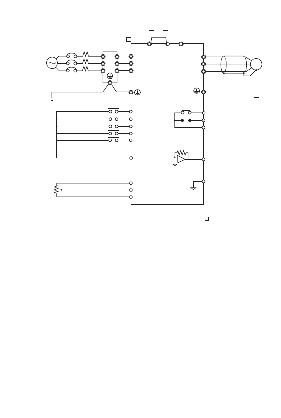
Standard Connections
Note 1: Connect single-phase 200 V AC to terminals R/L1 and S/L2 of the 3G3JV-AB .
Note 2: The braking resistor cannot be connected because no braking transistor is incorporated.
3G3JV PFI
Noise Filter
L1
L2
L3
3-phase 200 V AC
single-phase 200 V AC
(see note 1)
+1 +2
L1í
R/L1
L2í
S/L2
L3í
T/L3
M
Forward/Stop
Multi-function input 1 (S2)
Multi-function input 2 (S3)
Multi-function input 3 (S4)
Multi-function input 4 (S5)
Sequence input common
Frequency reference power
External frequency
adjuster
(2 kΩ 1/4 W min.)
supply 20mA at +12V
Frequency reference input
Frequency reference common
S1
S2
S3
S4
S5
SC
FS
FR
FC
Multi-function contact output
MA
NO
MB
NC
MC
Common
AM
Analogue monitor output
AC
Analogue monitor output
common
Page 3
NPN
PNP
SW7
SW7
OFF
SW8
SW8
VI
Control circuit
terminal block
Control circuit
terminal block
Forward/Stop
Multi-function Input 1
Multi-function input 2
Multi-function input 3
Multi-function input 4
Sequence Input Common
Frequency reference Power Supply
Frequency Reference Input
Frequency Reference Common
Multi-function output: NO
Multi-function output: NC
Multi-function output Common
Analogue Monitor output
Analogue Monitor output Common
Forward at ON/Stops at OFF
Set by parameter n36
(Reverse/Stop)
Set by parameter n37
(External Fault: NO)
Set by parameter n38 (Fault Reset)
Set by parameter n39
(Multi-step reference 1)
Common for S1 through S5
DC power supply for frequency
reference use
Input terminal for frequency
reference use
Common for frequency
reference use
Set by parameter n40
(during running)
Common for MA amd MB use
Set by parameter n44
(Output frequency)
Common for AM use
Photocoupler
8 mA at 24VDC
Note: NPN is the
default setting for
these terminals.
No external power
supply is required.
Refer to connections
shown below.
20mA at 12VDC
0 to 10VDC
(20Kohms)
4 to 20mA
0 to 20mA
Relay output
1A max. at 30VDC
and 250 VAC
12mA max. at 0 to
10VDC
S1
S2
S3
S4
S5
SC
FS
FR
FC
MA
MB
MC
AM
AC
Input
Output
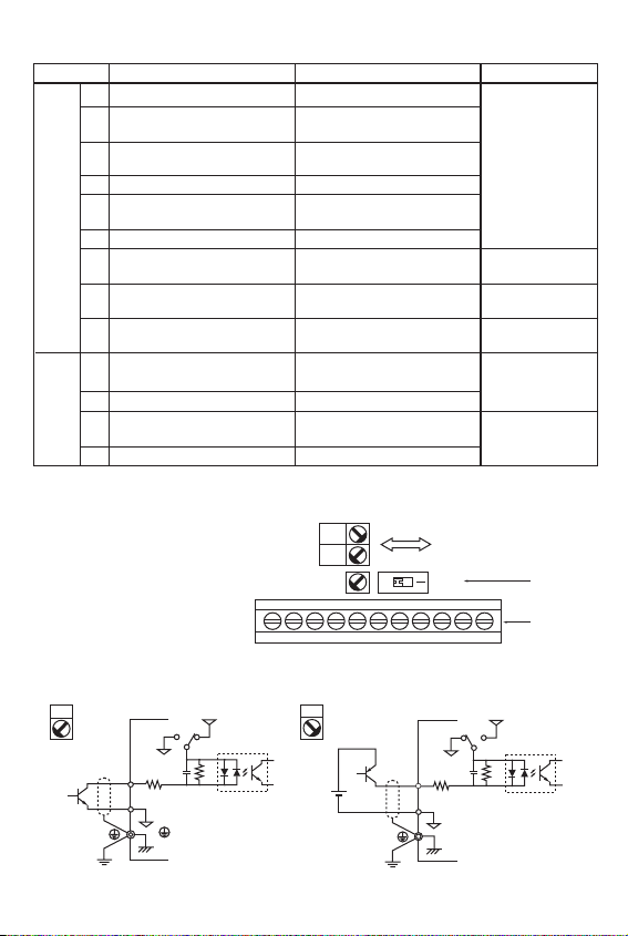
Control Circuit Terminals
Selecting Input Method
Symbol Name Function Signal Level
Note: Functions in parentheses are default settings.
Switches SW7 and SW8, both of which are
located above the control circuit terminals,
are used for input method selection.
Remove the front cover and optional cover
to use these switches.
Selecting Sequence Input Method
By using SW7, NPN or PNP input can be selected as shown below.
(Default setting)
NPN
GND
S1 to 5
3.3k
SC
GND
24V
SW7
0.1
µ
360
PNP
24 V DC
(±10%)
S1 to 5
24V
SW7
GND
0.1
µ
360
3.3k
SC
GND
Page 4

L
169
169
169
169
169
169
169
169
169
169
174
174
W
71
71
71
111
111
111
111
111
111
111
144
144
H
45
45
45
50
50
50
50
50
50
50
50
50
X
156
156
156
156
156
156
156
156
156
156
161
161
Y
51
51
51
91
91
91
91
91
91
91
120
120
d
5
5
5
5
5
M5
M5
M5
M5
M5
M5
M5
Model
3G3JV
AB001
AB002
AB004
AB007
AB015
A4002
A4004
A4007
A4015
A4022
A4030
A4040
Filter
3G3JV
PFI1010E
PFI1010E
PFI1010E
PFI1020E
PFI1020E
PFI3005E
PFI3005E
PFI3010E
PFI3010E
PFI3010E
PFI3020E
PFI3020E
Installation
Dimensions
Rated
Voltage
Model
3G3JV-
Supply Recommendations
Noise Filter Specifications
Y
W
X
d
H
L
H
128
128
128
128
128
128
128
128
128
128
128
128
H1
118
118
118
118
118
118
118
118
118
118
118
118
W
68
68
68
108
108
108
108
108
108
108
140
140
W1
56
56
56
96
96
96
96
96
96
96
128
128
D
70
70
112
129
154
81
99
129
154
154
161
161
AB001
AB002
AB004
AB007
AB015
A4002
A4004
A4007
A4015
A4022
A4030
A4040
Single Phase
200 VAC
MCCB (A)
5
5
10
20
20
5
5
5
10
10
20
20
Wire (mm2)
2
2
2
3.5
5.5
2
2
2
3.5
3.5
5.5
5.5
Two, 5 dia. holes
H1
H
5
6
W1
W
8.5
D
5
Page 5

Displays relevant data items, such as frequency reference,
output frequency and parameter set values.
Sets the frequency reference within a range between 0Hz
and the maximum frequency.
The frequency reference can be monitored or set while this
indicator is lit.
The output frequency of the Inverter can be monitored or
set while this indicator is lit.
The output current of the inverter can be monitored while
this indicator is lit.
The values set in U01 through U10 are monitored while
this indicator is lit.
The direction of rotation can be selected while this indicator
is lit when operating the Inverter with the RUN Key.
The operation of the Inverter through the Digital Operator
or according to the set parameteres is selectable while this
indicator is lit.
Note: The status of this indicator can be only monitored
while the Inverter is in operation. Any RUN
command input is ignored while this indicator is lit.
The parameter in n01 through to n79 can be set or monitored while this indicator is lit.
Note: While the Inverter is in operation, the parameters
can be only monitored and only some parameters
can be changed. Any RUN command input is
ignored while this indicator is lit.
Switches the setting and monitor item indicators in
sequence.
Parameter being set will be cancelled if this key is pressed
before entering the setting.
Increases multi-function monitor numbers, parameter numbers and parameter set values.
Decreases multi-function monitor numbers, parameter
numbers and parameter set values.
Enters multi-function monitor numbers, parameter numbers
and internal data values after they are set or changed.
Starts the Inverter running when the 3G3JV is in operation
with the Digital Operator.
Stops the Inverter unless parameter n06 is not set to
disable the STOP Key.
Data display
FREQ adjuster
FREF indicator
FOUT indicator
IOUT indicator
MNTR indicator
F/R indicator
LO/RE indicator
PRGM indicator
Mode Key
Increment Key
Decrement Key
Enter Key
RUN Key
STOP/RESET Key
Appearance Name Function
Keys
Data display
FREQ adjuster
Indicators
(Setting/Monitor
item indicators)
Page 6

Parameter Access:
0 - Limited Parameter access
1 - Full Parameter access
8 - Factory Parameter Initialise
Operation Mode Selection:
0 - Stop/Reset key or Keypad enabled
1 - Multi-function terminal input is enabled
Freq. Ref. Selection:
0 - Digital Operator
1 - Speeds from Digital Inputs (n21 - n28)
2 - Analogue Freq. Ref. (0-10V)
3 - Analogue Freq. Ref. (4-20mA)
4 - Analogue Freq. Ref. (0-20mA)
Maximum Frequency (FMAX)
Maximum Voltage (VMAX)
Maximum Voltage Frequency (FA)
Acceleration time 1
Deceleration time 1
Frequency Reference 1
Frequency Reference 2
"
Frequency Reference 8
Rated Motor Current
Multi-function input 1 (S2)
Multi-function input 2 (S3)
Multi-function input 3 (S4)
Multi-function input 4 (S5)
Multi-function output (MA/MB and MC)
Analogue Monitor Output:
0 - Output Frequency
1 - Output Current
Carrier Frequency Selection
DC Injection Braking Current
DC Injection Braking at Stop Time
DC Injection Braking at Start Time
Stall pevention during deceleration:
0 = Stall Prevention Enabled
1 = Braking Resistor Enabled
n01
n02
n03
n09
n10
n11
n16
n17
n21
n22
"
n28
n32
n36
n37
n38
n39
n40
n44
n46
n52
n53
n54
n55
0 to 9
0,1
0 to 4
20 to 400
1 to 255V
0.2 to 400
0.0 to 999
0.0 to 999
0.0 to FMAX
"
2 to 8, 10 to 22
0.2 to 8, 10 to 22
2 to 8, 10 to 22
2 to 8, 10 to 22,34
0 to 7, 10 to 17
0,1
1 to 4, 7 to 9
0 to 100%
0.0 to 25.5
0.0 to 25.5
0,1
1
0
0
60
200
60
10
10
6
0
"
0
0 to 150% of
rated inverter
output current
2
5
3
6
1
0
Varies with
the capacity
50
0.5
0
0
5-2
5-7
5-8
5-4
5-4
5-4
5-15
5-15
5-11
5-11
"
5-11
5-3
5-19
5-19
5-19
5-19
5-22
5-24
6-2
6-5
6-5
6-5
6-7
Parameter No. Description Range Default Manual Ref. Page
Quick Start Parameter List (Refer to manual for complete list)
Page 7

Power ON
Press the Mode Key repeatedly until the PRGM
indicator is lit.
Use the Increment or Decrement Key to set the
parameter number.
Press the Enter Key.
The data of the selected parameter number will be
displayed.
Use the Increment or Decrement Key to set the
data. At that time the display will flash.
Press the Enter Key so that the set value will be
entered and the data display will be lit. (see note 1)
The parameter number will be displayed.
In approx. 1s
Key sequence Indicator Display example
Explanation
Example of Parameter Settings
Multi-function Inputs
Value Function
2 Reverse/Stop
3 External fault (NO)
4 External fault (NC)
5 Fault reset
6 Multi-step speed reference 1
7 Multi-step speed reference 2
8 Multi-step speed reference 3
10 Inching command
12 External base block (NO)
13 External base block (NC)
17 Local/Remote selection
Multi-function Outputs
Value Function
0 Fault output
1 During RUN
2 Frequency agree
6 Overtorque being monitored (NO)
12 RUN mode
13 Inverter ready
15 Undervoltage in progress
Analogue Output Functions
Value Function
0 Output frequency
1 Output current
Note: Refer to Section 5-20 to 24 for full set value listings
Note 1: To cancel the set value, press the Mode Key instead. The parameter number will be displayed.
Note 2: There are parameters that cannot be changed while the Inverter is in operation. Refer to the list of
parameters. When attempting to change such parameters, the data display will not change by pressing
the Increment or Decrement Key.
Cancels
set data
In approximately 1s
Page 8

Check output for short circuit or ground fault.
The Load is too large, reduce it or use larger Inverter.
Check motor FLA rating compared to Inverter and V/F setting.
Load inertia is too large and the motor is regenerating.
Increase deceleration time (n020 or n022).
Connect an external braking resistor and set n092 to 1.
Check braking resistor and wiring.
Check mains power supply voltage and connections.
Check correct supply for Inverter being used.
Monitor for mains dips or interruptions.
Refer to manual for installation guidelines and recommendations.
Check cooling fan (if fitted).
Check V/F characteristic or reduce Carrier frequency.
Check and reduce the load.
Check V/F characteristic (Vmax and Fmax).
Increase the running speed of the motor.
Increase acceleration/deceleration times.
Check your control terminal wiring.
A multi-functional digital input has been set to 3 or 4.
Run signal must be removed before this can be reset.
Inverter must be stopped when Local/Remote switching
attempted.
Inverter must be stopped when Comms/Remote switching
attempted.
Check your control terminal wiring.
A multi-function digital input has been set to 12 or 13.
Forward and reverse run signal have been applied
simultaneously.
Overcurrent
Output current is higher than
250% of Inverter rated current.
Overvoltage
DC bus voltage has exceeded
detection level.
Main circuit undervoltage
DC bus voltage is below
detection level.
Unit overheated
Temperature inside the inverter
has exceeded 110°C.
Motor overload
The Inverter is protecting the motor
from overload based on an internal
I≈T calculation using n036 setting.
External fault
An external fault has been input.
Sequence error
Sequence input when Inverter
running.
External baseblock
An external baseblock command
has been input.
Sequence error has occurred
OC
OV
uV1
OH
OL1
EF*
SER
(flashing)
bb
(flashing)
EF
(flashing)
Fault Display Fault name and meaning Possible cause and remedy
Protective and Diagnostic Functions
Note: Refer to Section 7-2 for full fault code listings.
Improper procedures can result in personal injury or
equipment damage. Use the Quick Start Guide only if you
are familiar with standard safety precautions common to
variable speed drives. See Operation Manual I528 for
further details.
 Loading...