

Omron 3G3JV-AB007, 3G3JV-AB001, 3G3JV-AB015, 3G3JV-A4004, 3G3JV-A4002 Quick Start Manual
...
3G3JV
quick start guide
020 8450 8087
020 8450 0173
www.omron.co.uk
oeeuk_sales@eu.omron.com
1 Apsley Way, Staples Corner, London, NW2 7HF
Fax number
020 8233 1468
Factory automation technical support
24hr technical helpsheet/datasheet faxback service
020 8450 4646
General telephone enquiries and technical support
UK website
Direct e-mail address for sales enquiries
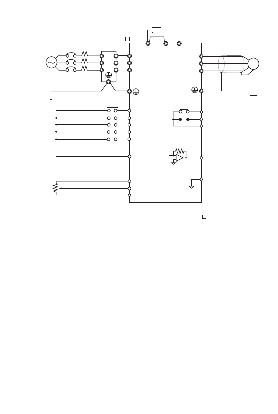
Standard Connections
Note 1: Connect single-phase 200 V AC to terminals R/L1 and S/L2 of the 3G3JV-AB .
Note 2: The braking resistor cannot be connected because no braking transistor is incorporated.
3G3JV PFI
Noise Filter
L1
L2
L3
3-phase 200 V AC
single-phase 200 V AC
(see note 1)
+1 +2
L1í
R/L1
L2í
S/L2
L3í
T/L3
M
Forward/Stop
Multi-function input 1 (S2)
Multi-function input 2 (S3)
Multi-function input 3 (S4)
Multi-function input 4 (S5)
Sequence input common
Frequency reference power
External frequency
adjuster
(2 kΩ 1/4 W min.)
supply 20mA at +12V
Frequency reference input
Frequency reference common
S1
S2
S3
S4
S5
SC
FS
FR
FC
Multi-function contact output
MA
NO
MB
NC
MC
Common
AM
Analogue monitor output
AC
Analogue monitor output
common
NPN
PNP
SW7
SW7
OFF
SW8
SW8
VI
Control circuit
terminal block
Control circuit
terminal block
Forward/Stop
Multi-function Input 1
Multi-function input 2
Multi-function input 3
Multi-function input 4
Sequence Input Common
Frequency reference Power Supply
Frequency Reference Input
Frequency Reference Common
Multi-function output: NO
Multi-function output: NC
Multi-function output Common
Analogue Monitor output
Analogue Monitor output Common
Forward at ON/Stops at OFF
Set by parameter n36
(Reverse/Stop)
Set by parameter n37
(External Fault: NO)
Set by parameter n38 (Fault Reset)
Set by parameter n39
(Multi-step reference 1)
Common for S1 through S5
DC power supply for frequency
reference use
Input terminal for frequency
reference use
Common for frequency
reference use
Set by parameter n40
(during running)
Common for MA amd MB use
Set by parameter n44
(Output frequency)
Common for AM use
Photocoupler
8 mA at 24VDC
Note: NPN is the
default setting for
these terminals.
No external power
supply is required.
Refer to connections
shown below.
20mA at 12VDC
0 to 10VDC
(20Kohms)
4 to 20mA
0 to 20mA
Relay output
1A max. at 30VDC
and 250 VAC
12mA max. at 0 to
10VDC
S1
S2
S3
S4
S5
SC
FS
FR
FC
MA
MB
MC
AM
AC
Input
Output
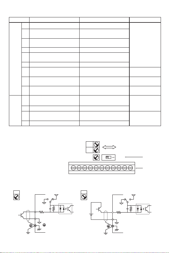
Control Circuit Terminals
Selecting Input Method
Symbol Name Function Signal Level
Note: Functions in parentheses are default settings.
Switches SW7 and SW8, both of which are
located above the control circuit terminals,
are used for input method selection.
Remove the front cover and optional cover
to use these switches.
Selecting Sequence Input Method
By using SW7, NPN or PNP input can be selected as shown below.
(Default setting)
NPN
GND
S1 to 5
3.3k
SC
GND
24V
SW7
0.1
µ
360
PNP
24 V DC
(±10%)
S1 to 5
24V
SW7
GND
0.1
µ
360
3.3k
SC
GND
 Loading...