

Page 1
Simple, Compact Inverters
3G3JV
Series
Note: Do not use this document to operate the Unit.
OMRON Corporation
FA Systems Division H.Q.
66 Matsumoto
Mishima-city, Shizuoka 411-8511
Japan
Tel:(81)55-977-9181
Fax:(81)55-977-9045
Regional Headquarters
OMRON EUROPE B.V.
Wegalaan 67-69, NL-2132 JD Hoofddorp
The Netherlands
Tel:(31)2356-81-300/Fax:(31)2356-81-388
OMRON ELECTRONICS LLC
1 East Commerce Drive, Schaumburg, IL 60173 U.S.A.
Tel:(1)847-843-7900/Fax:(1)847-843-8568
OMRON IDM Controls
9510 North Houston, Tx. 77088 U.S.A.
Tel: (1)800-395-4106/Fax: (1)713-849-4666
OMRON ASIA PACIFIC PTE. LTD.
83 Clemenceau Avenue, #11-01, UE Square,
Singapore 239920
Tel:(65)6835-3011/Fax:(65)6835-2711
Authorized Distributor:
Note: Specifications subject to change without notice.
Cat.No.I905-E1-05
Printed in Japan
0204-1M
Page 2
Contents
There has been a great demand for inverters that provide easier motor
speed control. OMRON's simple, compact 3G3JV Series meets the demand.
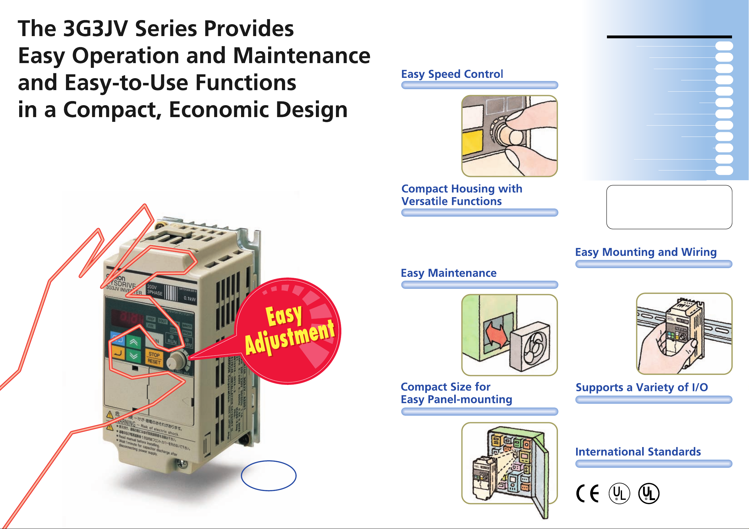
The 3G3JV Inverters provide versatile functions and ensure powerful performance.
The front panel of the 3G3JV Inverter has a frequency adjuster that makes it
possible to start the motor and easily control the motor speed.
The 3G3JV Inverters are easy to mount and operate and support a wide range
of applications for efficient motor control.
The frequency
adjuster on the front
panel makes it
possible to easily
adjust the speed of
the motor.
The Inverter can be
operated immediately
after the power is
turned ON.
The 3G3JV Inverter performs versatile speed control, such as
multi-step speed control up to a maximum of nine steps,
acceleration and deceleration (UP/DOWN) control, and jog
operations. Furthermore, the 3G3JV Inverter provides a variety
of useful functions, including slip compensation, overtorque
detection, and speed search functions.
Features
Applications
Nomenclature
Using Digital Operator
List of Parameters
Function of Each Parameter
Specifications
Dimensions
Standard Connections
Protective and Diagnostic Functions
Options
Inverter Models
This catalog provides information for the
selection of models, but does not provide
operational precautions. For information on
the operation of the 3G3JV Inverters and
operational precautions, be sure to read the
operation manual.
11
14
22
27
28
29
34
47
2
4
6
8
The cooling fan can
be easily mounted or
dismounted. The
cooling fan can also
be turned on only
when the 3G3JV
Inverter is in operation,
prolonging the life of
the fan.
The 3G3JV Inverters
are compact and
space-saving to
mount easily into a
panel.
The 3G3JV Inverter incorporates main circuit terminals
arranged in two rows on the top and bottom of the housing,
making it possible to
mount the 3G3JV
Inverter like a
contactor. The
optional DIN Track
Mounting Bracket
makes it possible to
easily mount a
3G3JV Inverter to a
DIN track.
The 3G3JV Inverter supports a variety of I/O, such as analog
inputs between 0 and 10V, 4 to 20 mA, or 0 to 20 mA, multifunction I/O, and analog monitor outputs. Multi-function inputs
can set to either PNP or NPN, providing flexibility in input
signals.
Actual
Standard models meet CE and UL/cUL standards.
Size
Three-phase 100 W at 200 V
68 x 128 x 78.5 mm (W x H x D)
2
C
3
Page 3
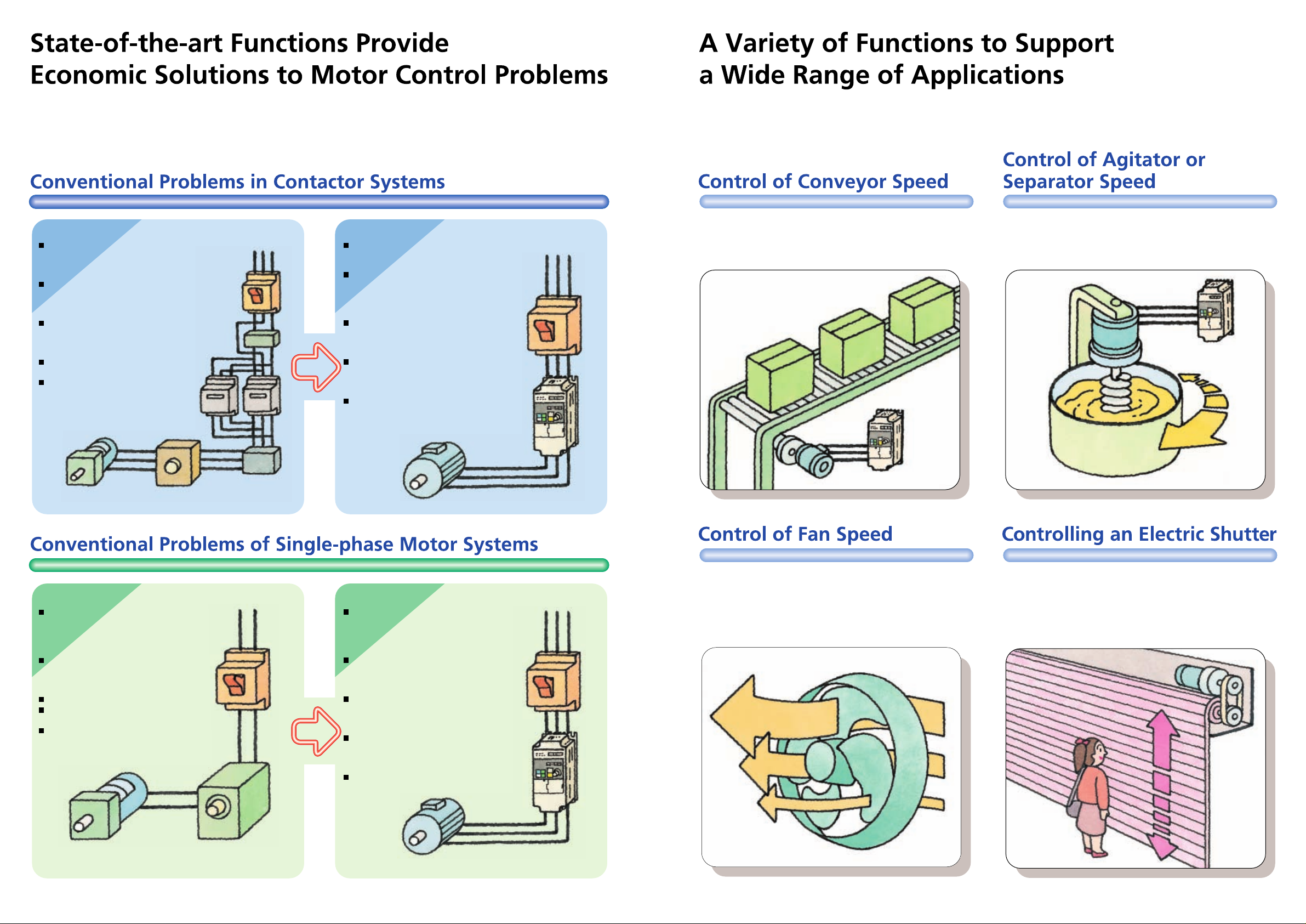
Conventional Systems
Conventional Systems
Relay contact welding occurs, which
may put the system and operators in
danger. Furthermore, the life of the
system is comparatively short.
The system employs a gearbox for
speed control, the designing and
adjustment of which require time and
labor.
To ensure the safety of the system, the
system needs peripheral safety
devices, the wiring of which requires
time and labor.
The motor always rotates at top speed,
consuming a high amount of power.
A strong shock is produced when the
motor is driven, which may cause
loads to shift, deteriorate the quality of
products, or put the system and
operators in danger.
Three-phase
inductive
motor
Gear box
Starter
Contactor
Breaker
Open-phase
detection
Current leakage
detection
3G3JV Inverter Solutions
3G3JV Inverter Solutions
A 3G3JV Inverter has no mechanical
relay contacts and thus allows a safe,
long-life system operation.
A 3G3JV Inverter performs versatile
speed control, such as multi-step speed
control for up to nine steps, acceleration
and deceleration (UP/DOWN) control,
and jog operations.
A 3G3JV Inverter provides a variety of
protective functions, such as a highspeed current limit, ground fault
protection, and undervoltage protection.
A 3G3JV Inverter drives the motor at
flexible speeds within the rated speed
range of the motor, thus reducing motor
power consumption.
A 3G3JV Inverter provides soft-start and
soft-stop functions, preventing loads
from shifting and deterioration of product
quality, while ensuring the safety of the
system.
Three-phase
inductive motor
Breaker
3G3JV
Inverter
A 3G3JV Inverter provides soft-start and soft-stop functions to
prevent loads from shifting. Furthermore, a 3G3JV Inverter
performs flexible speed control of the conveyor up to nine
steps.
A 3G3JV Inverter performs flexible speed control of a compact
agitator or separator.
Conventional Systems
Conventional Systems
A strong shock results at the moment
the motor is driven, which may cause
load shifting, deteriorates the quality of
products, or puts the system and
operators in danger.
The capacity of the motor is small.
Therefore, the rotation speed of the
motor will drop if a speed reducer is
used for the maintenance of the torque.
The rotation of the motor fluctuates.
Failures in the motor are not detected
by the host controller.
The types of available motors are
limited.
Gear box
4
Breaker
Speed controller
3G3JV Inverter Solutions
3G3JV Inverter Solutions
A 3G3JV Inverter provides soft-start and
soft-stop functions, preventing loads
from shifting and deterioration of
product quality while ensuring the safety
of the system.
The 3G3JV Inverters are available up to
a maximum motor capacity of 3.7 kW
and ensure smooth rotation speed and
torque in the motor.
A three-phase motor has less speed
fluctuation compared with a singlephase motor, ensuring the safe
operation of the system.
A 3G3JV Inverter can report errors in
contact outputs or data to a host
controller, such as a Programmable
Controller.
A wide range of motors is available.
Three-phase
inductive motor
Breaker
3G3JV
Inverter
A 3G3JV Inverter provides optimum control of fan speed
according to the room temperature. The 3G3JV Inverter has
no mechanical relay contacts, ensuring the safety and
reliability of the system compared with the ON/OFF control of
contactors. Optimum control of fan speed also saves energy.
A 3G3JV Inverter provides multi-step speed control to open
and close an electric shutter safely and efficiently. The shutter
opens quickly at a high speed, but closes at a medium-range
speed while the system checks the safety of the operation and
decelerates to low speed before it is fully closed to prevent
people from being caught by the shutter.
5
Page 4

Nomenclature
Panel
Top protection cover:
Remove this cover when wiring the upper terminal block.
Upper terminal block:
A terminal block on the input side of the main circuit.
Digital Operator:
Used to set parameters, perform various
monitoring, and start and stop the Inverter.
ALARM indicator:
RUN indicator:
Displays the operating status of the Inverter.
Alarm (Red): Lights when an error occurs. Flashes when a warning
occurs.
RUN (Green): Flashes when no RUN command is input during normal
status. Lights when a RUN command is input during normal status.
Optional cover:
Remove this cover when setting the input method selector.
Front cover:
Remove this cover when wiring the upper or lower terminal block.
Front cover mounting screw:
A screw for fixing the front cover.
Lower terminal blocks:
A terminal block on the output side of the main
circuit and a terminal block for the control circuit.
Bottom protection cover:
Remove this cover when wiring the lower terminal blocks.
6
Page 5
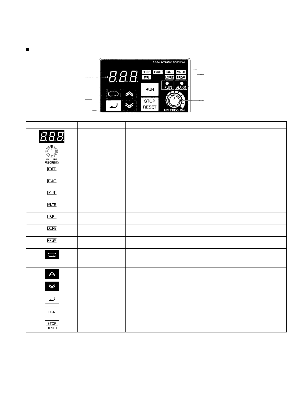
Digital Operator
Nomenclature
Data display
Keys
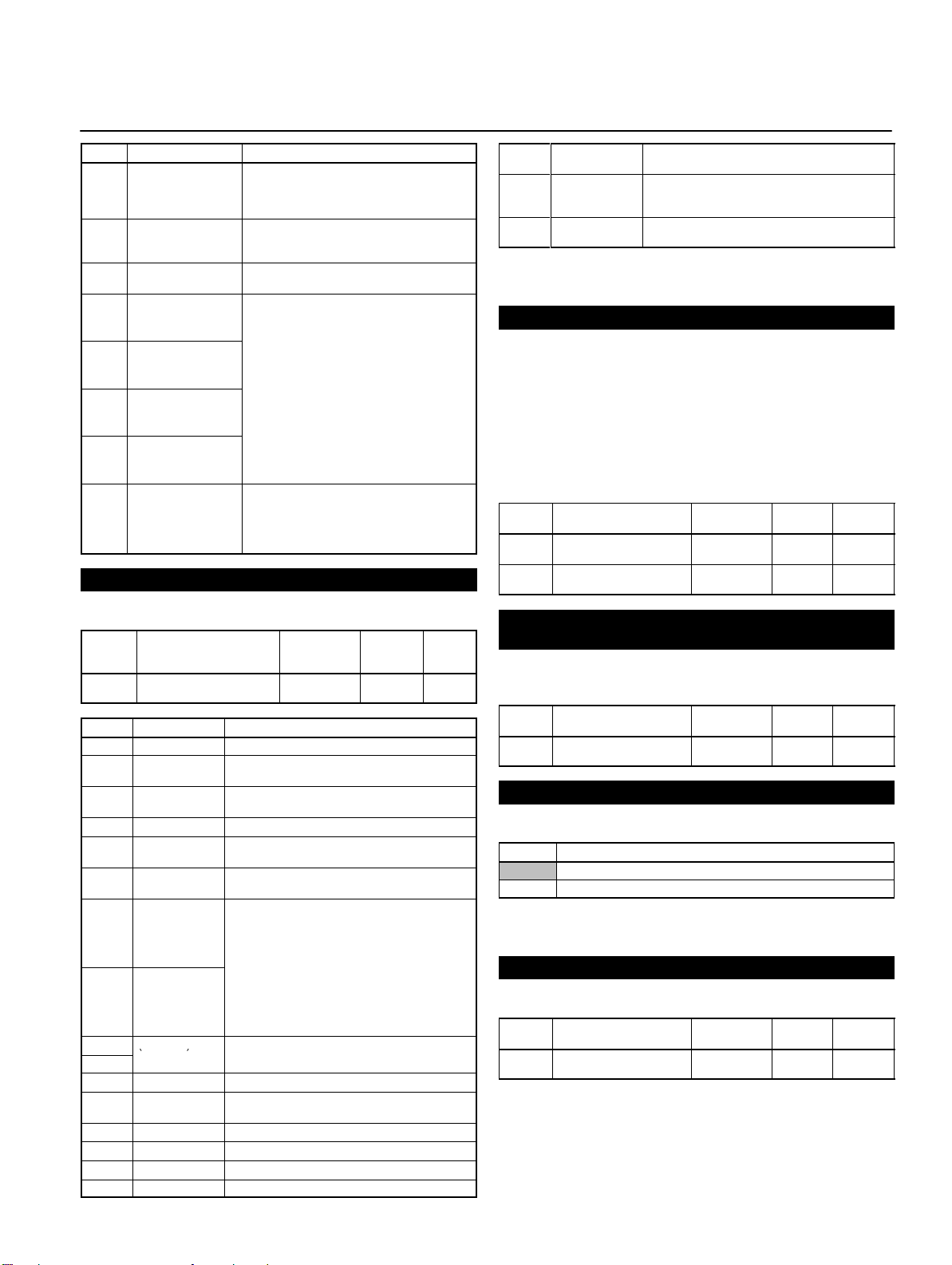
Appearance Name Function
Data display Displays relevant data items, such as frequency reference, output frequency,
and parameter set values.
Frequency adjuster Sets the frequency reference within a range between 0 Hz and the maximum
frequency.
Frequency reference
indicator
Output frequency
indicator
Output current
indicator
Multi-function
monitor indicator
Forward/Reverse
selection indicator
Local/Remote
selection indicator
Parameter setting
indicator
Mode Key Switches the setting and monitor item indicators in sequence.
Increment Key Increases multi-function monitor numbers, parameter numbers, and
Decrement Key Decreases multi-function monitor numbers, parameter numbers, and
Enter Key Enters multi-function monitor numbers, parameter numbers, and internal
RUN Key Starts the Inverter running when the 3G3JV is in operation with the Digital
The frequency reference can be monitored or set while this indicator is lit.
The output frequency of the Inverter can be monitored while this indicator is
lit.
The output current of the Inverter can be monitored while this indicator is lit.
The values set in U01 through U10 are monitored while this indicator is lit.
The direction of rotation can be selected while this indicator is lit when
operating the Inverter with the RUN Key.
The operation of the Inverter through the Digital Operator or according to the
set parameters is selectable while this indicator is lit. (See note 1.)
The parameters in n01 through n79 can be set or monitored while this
indicator is lit. (See note 2.)
Parameter being set will be canceled if this key is pressed before entering
the setting.
parameter set values.
parameter set values.
data values after they are set or changed.
Operator.
Indicators
(Setting/Monitor item
indicators)
FREQ adjuster
STOP/RESET Key Stops the Inverter unless parameter n06 is set to disable the STOP Key.
Used to reset the Inverter when an error occurs. (See note 3.)
Note: 1. The status of the local/remote selection indicator can be only monitored while the Inverter is in operation. Any RUN com-
mand input is ignored while this indicator is lit.
2. While the Inverter is in operation, the parameters can be only monitored and only some parameters can be changed. Any
RUN command input is ignored while the parameter setting indicator is lit.
3. For safety reasons, the reset function cannot be used while an operation instruction (forward/reverse) is being input. Turn
the operation instruction OFF before using this function.
7
Page 6
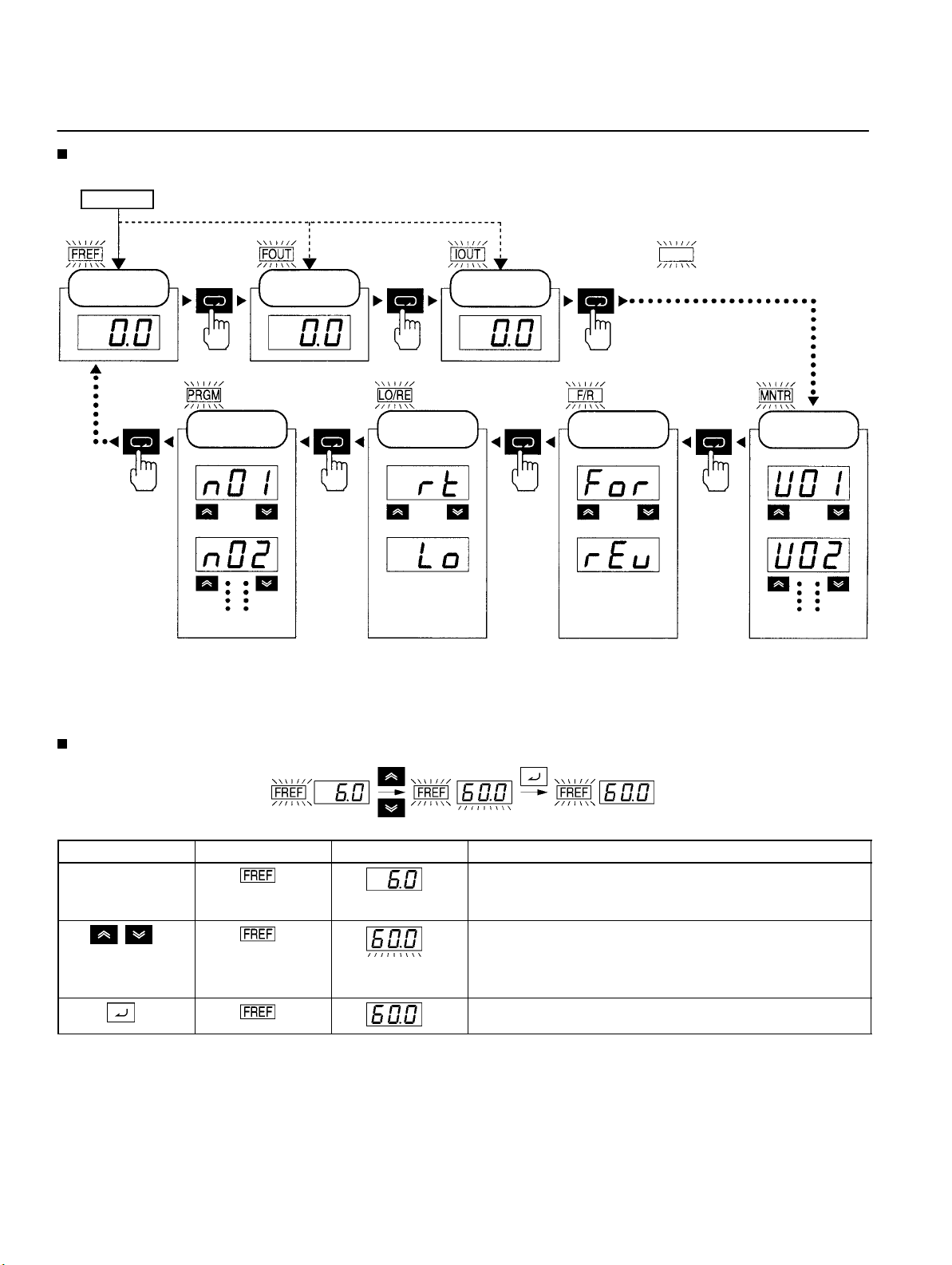
Using Digital Operator
Selecting Indicators
Power ON
Frequency
reference
Output
frequency
Output current
represents a lit indicator.
Parameter
settings
Parameter n01
Parameter n02
Other parameters
Note: If the power is turned OFF with the FOUT or IOUT indicator lit, the same indicator will light when the power is turned ON again.
In other cases, the FREF indicator will light when the power is turned ON.
Local/Remote
selection
Remote mode
Local mode
Direction of
rotation
Forward
Reverse
Multi-function
monitor
Frequency reference
Output frequency
Other monitor items
Example of Frequency Reference Settings
Flashing
Key sequence Indicator Display example Explanation
Power ON
Note If the FREF indicator has not been lit, press the Mode
Key repeatedly until the FREF indicator is lit.
Use the Increment or Decrement Key to set the frequency
reference.
The data display will flash while the frequency reference is
set. (see note 1)
Press the Enter Key so that the set value will be entered and
the data display will be lit. (see note 1)
Note: The Enter Key need not be pressed when performing the setting for n08. The frequency reference will change when the set
value is changed with the Increment or Decrement Key while the data display is continuously lit.
8
Page 7
Using Digital Operator
p
p
g(
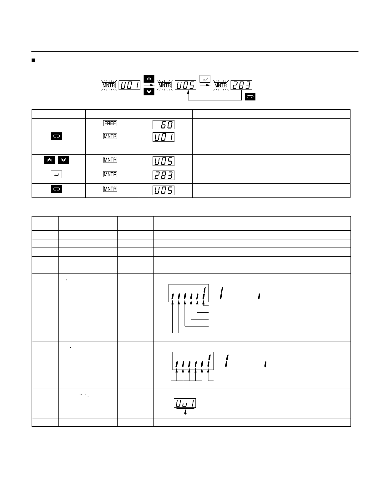
Example of Multi-function Display
Frequency
reference
Key sequence Indicator Display Explanation
DC bus
voltage
Monitor
data
Complete
Power ON
Press the Mode Key repeatedly until the MNTR indicator is
lit.
U01 will be displayed.
Use the Increment or Decrement Key to select the monitor
item to be displayed.
Press the Enter Key so that the data of the selected monitor
item will be displayed.
The monitor number display will appear again by pressing
the Mode Key.
Status Monitor
Item Display Display
unit
U01 Frequency reference Hz Monitors the frequency reference. (Same as FREF)
U02 Output frequency Hz Monitors the output frequency. (Same as FOUT)
U03 Output current A Monitors the output current. (Same as IOUT)
U04 Output voltage V Monitors the internal output voltage reference value of the Inverter.
U05 DC bus voltage V Monitors the DC voltage of the internal main circuit of the Inverter.
U06 Input terminal status ---
U07 Output terminal ---
status
U09 Error log (most
recent one)
---
Shows the ON/OFF status of inputs.
Terminal S1: Forward/Stop
Terminal S2: Multi-function input 1 (S2)
Terminal S3: Multi-function input 2 (S3)
Not
used
Shows the ON/OFF status of outputs.
Not
used
Displays the latest error.
Terminal S4: Multi-function input 3 (S4)
Terminal S5: Multi-function input 4 (S5)
Terminal MA: Multi-function contact
output
Function
: Input ON : No input
: Closed : Open
Error
U10 Software No. --- OMRON use only.
9
Page 8
Using Digital Operator
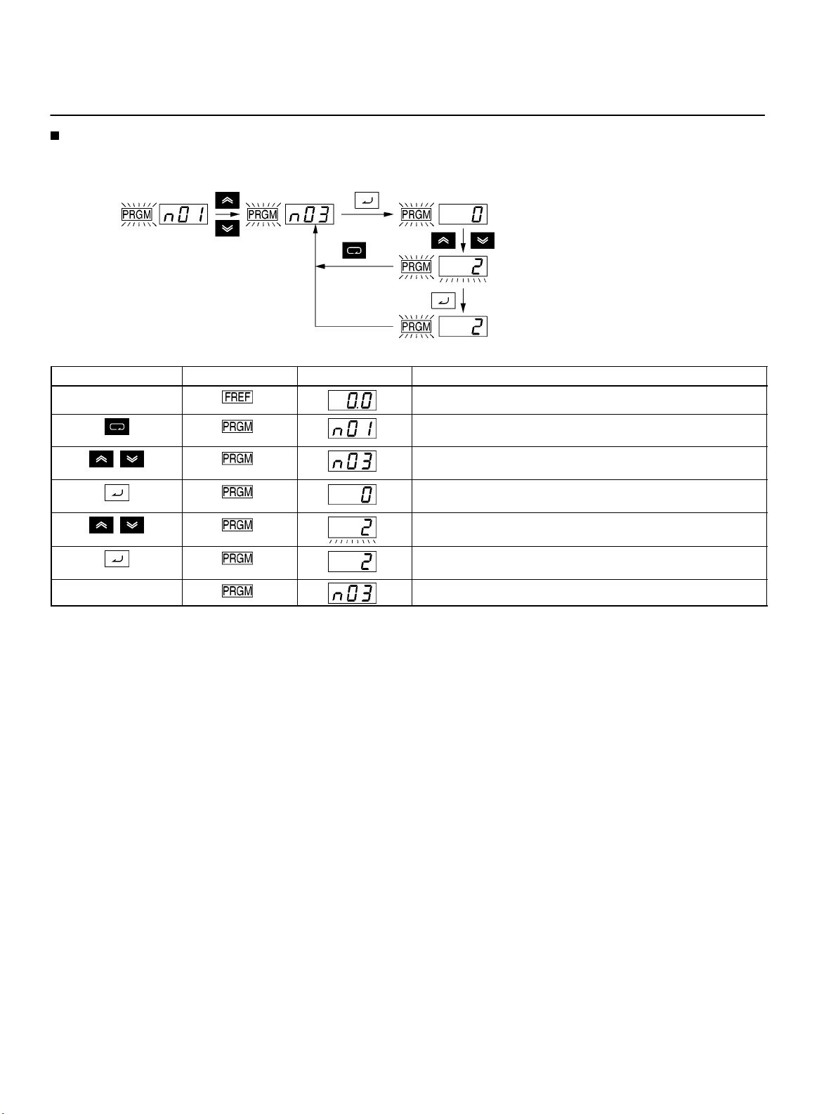
Example of Parameter Settings
The following example shows how to set 2 to enable the frequency reference control terminal for 0- to 10-V input in parameter n03
(Frequency Reference Selection).
Cancels set
data.
In approximately 1 s.
Key sequence Indicator Display example Explanation
Power ON
Press the Mode Key repeatedly until the PRGM indicator is
lit.
Use the Increment or Decrement Key to set the parameter
number.
Press the Enter Key.
The data of the selected parameter number will be displayed.
Use the Increment or Decrement Key to set the data. At that
time the display will flash.
Press the Enter Key so that the set value will be entered and
the data display will be lit. (see note 1)
In approximately 1 s. The parameter number will be displayed.
Note: 1. To cancel the set value, press the Mode Key instead. The parameter number will be displayed.
2. There are parameters that cannot be changed while the Inverter is in operation. Refer to the list of parameters. When attempting to change such parameters, the data display will not change by pressing the Increment or Decrement Key.
Enable the frequency reference
control terminal for 0- to 10-V input.
Complete
10
Page 9
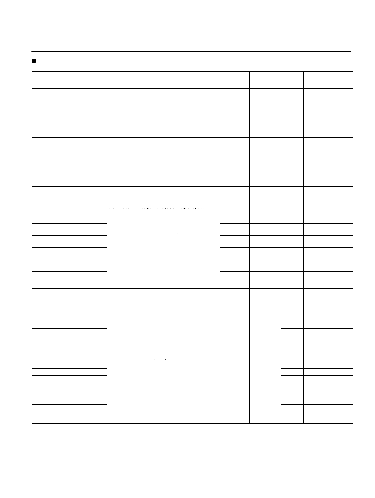
List of Parameters
the Inverter with output voltage per frequency set.
gp
(
Acceleration/Deceleration time
(Acceleration/De
Uqy
00
0
ti-step speed references (multi-function input). See
the reference pages for the relationship between
List of Parameters
Param-
eter
No.
n01 Parameter
n02 Operation mode selec-
n03 Frequency reference
n04 Interruption mode selec-
n05 Reverse rotation-prohibit
n06 STOP/RESET Key func-
n07 Frequency selection in
n08 Key sequential
n09 Maximum frequency
n10 Maximum voltage
n11 Maximum voltage fre-
n12 Middle output
n13 Middle output
n14 Minimum output
n15 Minimum output
n16 Acceleration time 1
n17 Deceleration time 1
n18 Acceleration time 2
n19 Deceleration time 2
n20 S-shape acceleration/de-
n21 Frequency reference 1
n22 Frequency reference 2
n23 Frequency reference 3
n24 Frequency reference 4
n25 Frequency reference 5
n26 Frequency reference 6
n27 Frequency reference 7
n28 Frequency reference 8 0.0 No 15
n29 Inching frequency com-
Name Description Setting
write-prohibit selection/
parameter initialization
tion
selection
tion
selection
tion selection
local mode
frequency setting
(FMAX)
(VMAX)
quency (FA)
frequency (FB)
frequency voltage (VC)
frequency (FMIN)
frequency voltage
(VMIN)
celeration characteristic
mand
Used to prohibit parameters to be written, sets
parameters, or change the monitor range of
parameters.
Used to initialize parameters to default values.
Used to select the input method for the RUN and STOP
commands in remote mode.
Used to set the input method for the frequency reference in remote mode.
Used to set the stopping method for use when the
STOP command is input.
Used to select the operation with the reverse command
input.
Used to select the stop method in remote mode with
n02 for operation mode selection set to 1.
Used to set the input method for the frequency reference in local mode.
Used to enable the Enter Key for setting the frequency
reference with the Increment and Decrement Keys.
Used to set the V/f pattern as the basic characteristic of
the Inverter with output voltage per frequency set.
Note Set the parameters so that the following condition
will be satisfied.
n14 x n12 < n11 x n09
Note The value set in n13 will be ignored if parameters
n14 and n12 are the same in value.
Acceleration time: The time required to go from 0% to
100% of the maximum frequency.
Deceleration time: The time required to go from 100%
to 0% of the maximum frequency.
Note The actual acceleration or deceleration time is ob-
tained from the following formula.
Acceleration/Deceleration time =
celeration time set value) × (Frequency reference
value) ÷ (Max. frequency)
Used to set S-shape acceleration/deceleration characteristics.
Used to set internal frequency references. 0.0 to max.
Note Frequency reference 1 is enabled in remote mode
with n03 for frequency reference selection set to 1.
Note These frequency references are selected with mul-
the reference pages for the relationship between
multi-step speed references and frequency references.
Used to set the inching frequency command. 6.0 No 15
Acceleration/De-
=
-
range
0, 1, 6, 8, 9 1 1 No 14
0, 1 1 0 No 14
0 to 4 1 0 No 14
0, 1 1 0 No 14
0, 1 1 0 No 14
0, 1 1 0 No 14
0, 1 1 0 No 14
0, 1 1 0 No 14
50.0 to 400 0.1 Hz 60.0 No 14
1 to 255
(see note 1)
0.2 to 400 0.1 Hz 60.0 No 14
0.1 to 399 0.1 Hz 1.5 No 14
1 to 255
(see note 1)
0.1 to 10.0 0.1 Hz 1.5 No 14
1 to 50
(see note 1)
0.0 to 999 0.1 s
-
0 to 3 1 0 No 15
frequency
Unit of
setting
(see note 2)
1 V 200 (see
1 V 12 (see
1 V 12 (see
0.1 Hz
Default
setting
note 1)
note 1)
note 1)
10.0 Yes 15
10.0 Yes 15
10.0 Yes 15
10.0 Yes 15
6.0 No 15
0.0 No 15
0.0 No 15
0.0 No 15
0.0 No 15
0.0 No 15
0.0 No 15
Changes
during op-
eration
No 14
No 14
No 14
Refer-
ence
page
Note: 1. With 400-class Inverters, the default settings and maximum values setting ranges for n10, n13, and n15 are double those
given in the table.
2. Values longer than 3 digits are rounded up to the next unit multiple.
11
Page 10

List of Parameters
limits in percentage based on the maximum frequency
minals S2 through S5.
n39
Multi-function input 4
2 to 34
16No
16
references.
qyjp
Note These values must satisfy the following condi
UpC g
Param-
eter
No.
n30 Frequency reference
n31 Frequency reference
n32 Rated motor current Used to set the rated motor current for motor overload
n33 Motor protection
n34 Motor protective
n35 Cooling fan opera-
n36 Multi-function input 1
n37 Multi-function input 2
n38 Multi-function input 3
n39 Multi-function input 4 2 to 34 1 6 No 16
n40 Multi-function output
n41 Frequency reference
n42 Frequency reference
n43 Analog frequency
n44 Analog monitor
n45 Analog monitor
n46 Carrier frequency
n47 Momentary power
n48 Fault retry Used to set the number of times the Inverter is reset
n49 Jump frequency 1
n50 Jump frequency 2
n51 Jump width
n52 DC control current
n53 Interruption DC
n54 Startup DC control
n55 Stall prevention
n56 Stall prevention level
n57 Stall prevention level
n58 Frequency detection
Name Description Setting
Used to set the upper and lower frequency reference
upper limit
lower limit
characteristics
time setting
tion function
(Input terminal S2)
(Input terminal S3)
(Input terminal S4)
(Input terminal S5)
(MA/MB and MC
output terminals)
gain
bias
reference filter time
output
output gain
selection
interruption compensation
control time
time
during deceleration
during acceleration
during operation
level
limits in percentage based on the maximum frequency
as 100%.
detection (OL1) based on the rated motor current.
Note Motor overload detection (OL1) is disabled by set-
ting the parameter to 0.0.
Used to set the motor overload detection (OL1) for the
electronic thermal characteristics of the motor.
Used to set the electric thermal characteristics of the
motor to be connected in 1-minute increments.
Used to operate the Cooling Fan of the Inverter while
the Inverter is turned on or only while the Inverter is in
operation.
Used to select the functions of multi-function input terminals S2 through S5.
Used to select the functions of multi-function output
terminals.
Used to the input characteristics of analog frequency
references.
Used to set the digital filter with a first-order lag for analog frequency references to be input.
Used to set the output frequency or current as a monitored item.
Used to set the output characteristics of analog monitor
output.
Used to set the carrier frequency. 1 to 4, 7 to91 Varies
Used to specify the processing that is performed when
a momentary power interruption occurs.
and restarted automatically in the case the Inverter has
an overvoltage fault, overcurrent fault, or ground fault.
Used to set the frequency jump function.
tion: n49 y n50
Used to impose DC on the induction motor for braking
control.
Used to select a function to change the deceleration
time of the motor automatically so that there will be no
overvoltage imposed on the motor during deceleration.
Used to select a function to stop the acceleration of the
motor automatically for stall prevention during
acceleration.
Used to select a function to reduce the output
frequency of the Inverter automatically for stall
prevention during operation.
Used to set the frequency to be detected. 0.0 to 400 0.1 Hz 0.0 No 19
range
0 to 110 1% 100 No 16
0 to 110 1% 0 No 16
0.0 to 120%
of rated output current
0 to 2 1 0 No 16
1 to 60 1 min 8 No 16
0, 1 1 0 No 16
2 to 22 1 2 No 16
0 to 22 1 5 No 16
2 to 22 1 3 No 16
0 to 7, 10 to171 1 No 17
0 to 255 1% 100 Ye s 17
–99 to 99 1% 0 Ye s 17
0.00 to 2.00 0.01 s 0.10 No 17
0, 1 1 0 No 17
0.00 to 2.00 0.01 1.00 Ye s 17
0 to 2 1 0 No 18
0 to 10 1 0 No 18
0.0 to 400 0.1 Hz 0.0 No 18
0.0 to 400 0.1 Hz 0.0 No 18
-
-
0.0 to 400 0.1 Hz 0.0 No 18
0 to 100 1% 50 No 18
0.0 to 25.5 0.1 s 0.5 No 18
0.0 to 25.5 0.1 s 0.0 No 18
0, 1 1 0 No 18
30 to 200 1% 170 No 19
30 to 200 1% 160 No 19
Unit of
setting
(see note)
0.1 A Varies
Default
setting
with the
capacity.
with the
capacity.
Changes
during op-
eration
No 16
No 18
Reference
page
Note: Values longer than 3 digits are rounded up to the next unit multiple.
12
Page 11
List of Parameters
OO
g
Param-
eter
No.
n59 Overtorque
n60 Overtorque
n61 Overtorque
n62 UP/DOWN
n63 Torque
n64 Motor rated slip Used to set the rated slip value of the motor in use. 0.0 to 20.0 0.1 Hz Varies
n65 Motor no-load
n66 Slip compensation
n67 Slip compensation
n68 to
n74
n75 Low-speed carrier
n76
n77
n78 Error log Used to display the latest error recorded.
Name Description Setting
Used to enable or disable overtorque detection and
detection function
selection
detection level
detection time
command frequency
memory
compensation gain
current
gain
time constant
OMRON’s control
reference use
frequency reduction
selection
OMRON’s control
reference use
select the processing method after overtorque
detection.
Used to set overtorque detection level. 30 to 200 1% 160 No 19
Used to set the detection time of overtorque. 0.1 to 10.0 0.1 s 0.1 No 19
Used to store the adjusted frequency reference with the
UP/DOWN function.
Used to set the gain of the torque compensation
function.
Used to set the no-load current of the motor in use
based on the rated motor current as 100%.
Used to set the gain of the slip compensation function. 0.0 to 2.5 0.1 0.0 Ye s 21
Used for the response speed of the slip compensation
function.
Do not change the set value. --- --- --- --- ---
Used to select a function to reduce the carrier
frequency when Inverter is at low speed.
Do not change the set value. --- --- --- --- ---
range
0 to 4 1 0 No 19
0, 1 1 0 No 20
0.0 to 2.5 0.1 1.0 Ye s 21
0 to 99 1% Varies
0.0 to 25.5 0.1 s 2.0 No 21
0.1 1 0 No ---
--- --- --- --- ---
Unit of
setting
(see note)
Default
setting
with the
capacity.
with the
capacity.
Changes
during op-
eration
Yes 21
No 21
Reference
page
Display
Note “– – –” will be displayed if no error has been re-
corded.
Note This parameter is monitored only.
n79 Software number Used to display the software number of the Inverter for
OMRON’s control reference use.
Note This parameter is monitored only.
Note: Values longer than 3 digits are rounded up to the next unit multiple.
--- --- --- --- ---
13
Page 12
Function of Each Parameter
Note: The shaded values indicate default settings.
Parameter Write-prohibit Selection/Parameter
Initialization (n01)
This parameter makes it possible to write-prohibit parameters,
change the parameter set or displayed range, or initialize all parameters to default values.
Value Description
0 Only n01 can be displayed and set. The n02 through n79
1 The n01 through n79 parameters can be displayed and set.
6 Only the error log memory is cleared.
8 Enables the initialization of all parameters in 2-wire sequence so
9 Enables the initialization of all parameters in 3-wire sequence.
parameters can be displayed only.
that the parameters will return to default values.
Operation Mode Selection (n02)
Select the method of operation mode input to start or stop the Inverter in remote mode.
Value Description
0 The RUN and STOP/RESET Keys of the Digital Operator are
1 Multi-function input in 2- or 3-wire sequence through the control
Note: In local mode, RUN commands can be entered using the
enabled.
circuit terminals is enabled.
Digital Operator only.
Reverse Rotation-prohibit Selection (n05)
Select the operation to be performed when the reverse rotation
command is input.
Value Description
0 Reverse rotation possible (command accepted)
1 Reverse rotation prohibited (command not accepted)
STOP/RESET Key Function Selection (n06)
When parameter n02 is set to 1, set whether or not to use the
STOP/RESET Key of the Digital Operator to stop the Inverter in
remote mode. The STOP/RESET Key is always enabled in local
mode regardless of the setting in n02.
Value Description
0 The STOP/RESET Key of the Digital Operator is enabled.
1 The STOP/RESET Key of the Digital Operator is disabled.
Frequency Reference Selection (n07)
(Local Mode)
Select the input method of frequency references in local mode.
Value Description
0 The FREQ adjuster of the Digital Operator is enabled.
1 Key sequences on the Digital Operator are enabled.
Frequency Reference Selection (n03)
(Remote Mode)
Select the method for inputting the frequency reference to the Inverter in remote mode.
Value Description
0 The FREQ adjuster of the Digital Operator is enabled.
1 Frequency reference 1 (n21) is enabled.
2 The frequency reference control terminal (for 0- to 10-V input) is
3 The frequency reference control terminal (for 4- to 20-mA current
4 The frequency reference control terminal (for 0- to 20-mA current
enabled.
input) is enabled.
input) is enabled.
Interruption Mode Selection (n04)
Select the stopping method to be used when the STOP command is input.
Value Description
0 Frequency deceleration stop (Decelerates to stop in preset time.)
1 Free running (Output shut OFF by STOP command.)
Key Sequential Frequency Setting (n08)
Select whether to enable the Enter Key when setting the frequency reference with the Increment and Decrement Keys on
the Digital Operator.
Value Description
0 The Enter Key is enabled. (The setting is made valid by pressing
1 The Enter Key is disabled. (The setting is directly treated as a
the Enter Key.)
frequency reference without the Enter Key being pressed.)
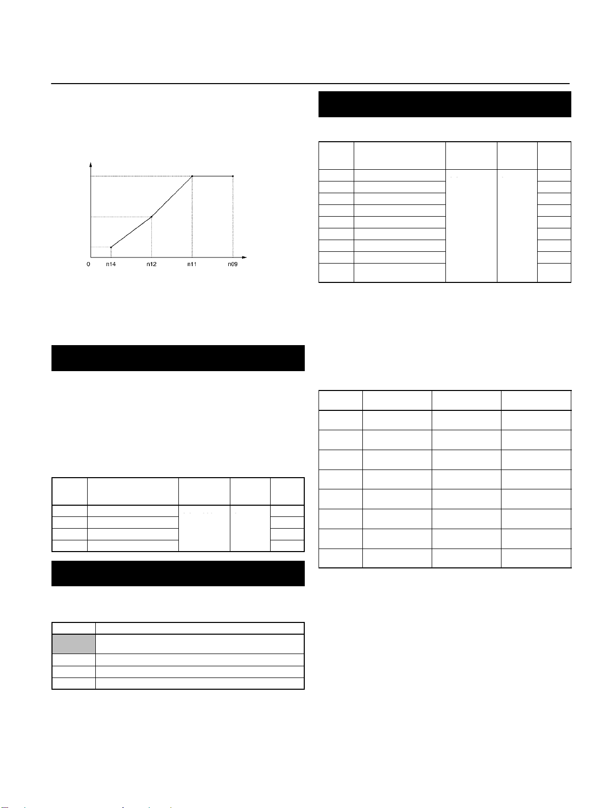
V/f Pattern Settings (n09 to n15)
Set the V/f pattern as the basic characteristic of the Inverter with
output voltage per frequency set.
Value Name Setting
n09 Maximum Frequency
n10 Maximum Voltage (VMAX) 1 to 255 1 V 200
n11 Maximum Voltage
n12 Middle Output Frequency
n13 Middle Output Frequency
n14 Minimum Output
n15 Minimum Output
(FMAX)
Frequency (FA)
(FB)
Voltage (VC)
Frequency (FMIN)
Frequency Voltage (VMIN)
range
50.0 to 400 0.1 Hz 60.0
0.2 to 400 0.1 Hz 60.0
0.1 to 399 0.1 Hz 1.5
1 to 255 1 V 12
0.1 to 10.0 0.1 Hz 1.5
1 to 50 1 V 12
Unit of
setting
Default
settings
14
Page 13
Function of Each Parameter
0 0 999
0
00
1)
Note: For n09, n11, and n12, the unit of setting is as follows:
Values will be set in 0.1-Hz increments if the frequency is
less than 100 Hz and 1-Hz increments if the frequency is
100 Hz or greater.
Output
voltage (V)
n10
n13
n15
Frequency
(Hz)
Note: 1. Set the parameters so that the following condition will
be satisfied.
n14 x n12 < n11 x n09
2. The value set in n13 will be ignored if parameters n14
and n12 are the same in value.
Acceleration/Deceleration Time Settings
(n16 to n19)
The acceleration time is the time required to go from 0% to 100%
of the maximum frequency and the deceleration time is the time
required to go from 100% to 0% of the maximum frequency. The
actual acceleration or deceleration time is obtained from the following formula.
Acceleration/Deceleration time =
(Acceleration/Deceleration time set value) × (Frequency reference value) ÷ (Max. frequency)
Value Name Setting
n16 Acceleration time 1
n17 Deceleration Time 1
n18 Acceleration time 2 10.0
n19 Deceleration Time 2 10.0
range
0.0 to 999 0.1 s
Unit of
setting
Default
set-
tings
10.0
10.0
S-shape Acceleration/Deceleration Characteristic
(n20)
Any one of three S-shape acceleration/deceleration times (0.2,
0.5, and 1.0 s) is selectable.
Value Description
0 No S-shape acceleration/deceleration characteristic
1 S-shape acceleration/deceleration characteristic time is 0.2 s
2 S-shape acceleration/deceleration characteristic time is 0.5 s
3 S-shape acceleration/deceleration characteristic time is 1.0 s
(Trapezoidal acceleration/deceleration)
Setting the Frequency References 1 to 8 and the
Inching Frequency Command (n21 to n28 and n29)
Set internal frequency references.
Value Name Setting
n21 Frequency reference 1
n22 Frequency reference 2
n23 Frequency reference 3
n24 Frequency reference 4 0.0
n25 Frequency reference 5 0.0
n26 Frequency reference 6 0.0
n27 Frequency reference 7 0.0
n28 Frequency reference 8 0.0
n29 Inching frequency com-
mand
range
0.0 to max.
frequency0(see note
Note: 1. Values will be set in 0.1-Hz increments if the frequency is less
than 100 Hz and 1-Hz increments if the frequency is 100 Hz
or over.
2. Frequency reference 1 is enabled with n03 for frequency reference selection set to 1. (Remote mode)
3. Frequency references 1 to 8 are enabled by setting multistep speed references 1, 2, and 3 in n36 to n39 for multi-function input. Refer to the following table for the relationship between multi-step speed references 1 to 3 and frequency references 1 to 8.
Frequency
reference
Frequency
reference 1
Frequency
reference 2
Frequency
reference 3
Frequency
reference 4
Frequency
reference 5
Frequency
reference 6
Frequency
reference 7
Frequency
reference 8
Multi-step speed
reference 1
OFF OFF OFF
ON OFF OFF
OFF ON OFF
ON ON OFF
OFF OFF ON
ON OFF ON
OFF ON ON
ON ON ON
Multi-step speed
reference 2
Note: 1. “ON” and “OFF” represent “input ON” and “input OFF,” re-
spectively.
2. Inching frequency commands take precedence over multistep speed references.
Unit of
setting
0.1 Hz
Multi-step speed
6.0
0.0
0.0
6.0
reference 3
Default
set-
tings
Note: When the S-shape acceleration/deceleration character-
istic time is set, the acceleration and deceleration times
will be lengthened according to the S-shape at the beginning and end of acceleration/deceleration.
15
Page 14
Function of Each Parameter
8.
Frequency Reference Upper and Lower Limit
Settings (n30 and n31)
Set the upper and lower frequency reference limits in percentage based on the maximum frequency as 100%.
Value Name Setting
n30 Frequency Reference
n31 Frequency Reference
Upper Limit
Lower Limit
range
0 to 110 1% 100
0 to 110 1% 0
Unit of
setting
Default
settings
Note: If n31 is set to a value less than the minimum output fre-
quency (FMIN) (n14), the Inverter will have no output
when a frequency reference less than the minimum output frequency input is ON.
Rated Motor Current Setting (n32)
Set the rated motor current as the reference value for motor
overload detection (OL1).
Note: 1. Setting 0.0 disables the motor overload detection (OL1) func-
Value Name Setting range Unit of
n32 Rated Motor Current 0.0% to 120% (A) of
tion.
2. The rated motor current value is factory-set for each Inverter
according to the maximum applicable motor capacity.
Default
settings
the capacity.
rated output current
of Inverter
setting
0.1 A Varies with
Motor Protection Characteristic Selection (n33)
Set the motor overload detection (OL1) for the electronic thermal
characteristics of the motor.
Value Description
0 Protection characteristics for general-purpose induction motors
1 Protection characteristics for Inverter-dedicated motors
2 No protection
Note: When connecting multiple motors to one Inverter, set 2
(equivalent to n32 = 0.0). In addition, take overload prevention measures by mounting a thermal relay in each
motor, for example.
Motor Protective Time Setting (n34)
Set the electronic thermal characteristics of the motor to be connected in 1-minute increments.
Value Name Setting
n34 Motor Protective Time
Setting
range
1 to 60 1 min 8
Note: 1. The default setting does not need any changes in normal op-
eration.
2. To set the parameter according to the characteristics of the
motor, confirm the thermal time constant with the motor
manufacturer and set the parameter with some margin. In
other words, set the value a little shorter than the thermal time
constant.
3. To detect motor overloading more quickly, reduce the set value, provided that it does not cause any application problems.
Unit of
setting
Default
settings
Cooling Fan Operation Function Selection (n35)
This parameter is used to operate the cooling fan of the Inverter
while the Inverter is turned on or only while the Inverter is in operation.
Value Description
0 The fan rotates only while the RUN command is input and for 1
1 The fan rotates while the Inverter is turned ON.
Note: 1. This parameter is available only if the Inverter incorporates a
minute after the Inverter stops operating.
cooling fan.
2. If the operation frequency of the Inverter is low, the life of the
fan can be prolonged by setting the parameter to 0.
Multi-function Input Selection (n36 to n39)
Select the functions of multi-function input terminals S2 to S5.
Value Name Setting
n36 Multi-function Input 1
n37 Multi-function Input 2
n38 Multi-function Input 3
n39 Multi-function Input 4
Value Function Description
0 Forward/Reverse
2 Reverse/Stop Reverse rotation command (2-wire
3 External fault (NO) ON: External fault
4 External fault (NC) OFF: External fault
5 Fault reset ON: Fault reset
6 Multi-step speed
7 Multi-step speed
8 Multi-step speed
10 Inching frequency
11 Acceleration/Decel-
12 External base block
13 External base block
14 Search command
(S2)
(S3)
(S4)
(S5)
rotation command
reference 1
reference 2
reference 3
command
eration time selection
command (NO)
command (NC)
(Searching starts
from maximum frequency)
3-wire sequence (to be set in n37 only)
This setting overrides the n36 setting.
sequence) (ON: Reverse)
Note Disabled while RUN command is
Signals to select frequency references 1 to
8.
ON: Inching frequency command
ON: Acceleration/deceleration time 2
ON: Output shut OFF (while motor coasting
to a stop and “bb” flashing)
OFF: Output shut OFF (with motor free
running and “bb” flashing)
ON: Speed search (Searching starts from
n09)
range
2 to 8, 10 to221 2
0, 2 to 8, 10
to 22
2 to 8, 10 to221 3
2 to 8, 10 to
22, 34
S1: RUN input (RUN when ON)
S2: STOP input
(STOP when OFF)
S3: Forward/Reverse rotation
command
(ON: Reverse)
input
Unit of
setting
1 5
1 6
Default
settings
16
Page 15
Function of Each Parameter
tact opened
(
ON (no reset required)
• Overtorque detection level (n60)
()
Value Function Description
15 Search command
(Searching starts
from preset frequency)
16 Acceleration/Decel-
eration-prohibit command
17 Local or remote
selection
19 Emergency stop
fault (NO)
20 Emergency stop
alarm (NO)
21 Emergency stop
fault (NC)
22 Emergency stop
alarm (NC)
34 Up or down com-
mand
Multi-function Output Selection (n40)
Select the functions of multi-function output terminals.
Value Name Setting
n40 Multi-function Output (MA/
Value Function Description
0 Fault output ON: Fault output
1 Operation in
2 Frequency
3 Idling ON: Idling
4 Frequency
5 Frequency
6 Overtorque
7 Overtorque
8
9
10 Alarm output ON: Alarm being detected (Nonfatal error)
11 Base block in
12 RUN mode ON: Local mode
13 Inverter ready ON: Inverter ready to operate
14 Fault retry ON: Fault retry
Value Function Description
MB and MC)
progress
detection
detection 1
detection 2
being monitored
(NO-contact
output)
being monitored
(NC-contact
output)
(Not used) ---
progress
ON: Speed search (Searching starts from
the frequency specified by n03.)
ON: Acceleration/Deceleration is on hold
ON: Local mode (operated with the Digital
Operator)
The Inverter stops according to the setting in
n04 for interruption mode selection when the
emergency stop input turns ON.
Note NO: Emergency stop with the con-
Note Fault: Fault output is ON and reset
Note “STP” is displayed (lit with fault in-
Up or down command (set in n39 only)
This setting overrides the n38 setting.
ON: Operation in progress
ON: Frequency detection
ON: Output frequency y frequency detection
level (n58)
ON: Output frequency x frequency detection
level (n58)
Output if any of the following parameter
conditions is satisfied.
• Overtorque detection function selection (n59)
• Overtorque detection level (n60)
• Overtorque detection time (n61)
Note NO contact: ON with overtorque be-
ON: Base block in progress
tact closed.
NC: Emergency stop with the con-
with RESET input. Alarm output is
ON
put ON and flashes with alarm input ON)
S4: Up command
S5: Down command
range
0 to 7, 10 to171 1
ing detected; NC contact: OFF with
overtorque being detected
.
no reset required).
Unit of
setting
.
Default
set-
tings
15 UV in progress ON: Undervoltage being monitored (main circuit
16 Rotating in
17 Speed search
reverse
direction
in progress
undervoltage UV or UV1 detected)
ON: Rotating in reverse direction
ON: Speed search in progress
Note: Use “operation in progress” or “frequency detection 1/2”
for the timing of the external brake.
Gain and Bias Settings (n41 and n42)
Set the input characteristics of analog frequency references in
n41 (for the frequency reference gain) and n42 (for the frequency reference bias).
Set the frequency of maximum analog input (10 V or 20 mA) in
n41 as percentage based on the maximum frequency as 100%.
Set the frequency of minimum analog input (0 V, 0 mA, or 4 mA)
in n42 as percentage based on the maximum frequency as
100%.
Value Name Setting
n41 Frequency Reference
n42 Frequency Reference
Gain
Bias
range
0 to 255 1% 100
–99 to 99 1% 0
Unit of
setting
Default
settings
Analog Frequency Reference Filter Time Setting
(n43)
The digital filter with a first-order lag can be set for analog frequency references to be input.
Value Name Setting
n43 Analog Frequency Refer-
ence Filter Time
range
0.00 to 2.00 0.01 s 0.10
Unit of
setting
Default
settings
Analog Monitor Output Setting (n44)
Set a monitored item for analog monitor output.
Value Description
0 Output frequency (Reference: 10 V at max. frequency)
1 Output current (Reference: 10 V with rated output current)
Note: The values in parentheses are applicable when n45 is
set to 1.00.
Analog Monitor Output Gain Setting (n45)
Set the output characteristics of analog monitor output.
Value Name Setting
n45 Analog Monitor Output
Gain
range
0.00 to 2.00 0.01 1.00
Unit of
setting
Default
settings
17
Page 16

Function of Each Parameter
Carrier Frequency Selection (n46)
Set the carrier frequency.
Value Description
1 2.5 kHz
2 5.0 kHz
3 7.5 kHz
4 10.0 kHz
7 2.5 kHz (12×): 12 times as high as output frequency (between 1.0
8 2.5 kHz (24×): 24 times as high as output frequency (between 1.0
9 2.5 kHz (36×): 36 times as high as output frequency (between 1.0
and 2.5 kHz)
and 2.5 kHz)
and 2.5 kHz)
Note: Normally, the factory setting need not be changed.
Momentary Power Interruption Compensation
(n47)
The parameter specifies the processing that will be performed
when a momentary power interruption occurs.
Value Description
0 Disabled.
1 The Inverter will continue operating if power is restored within 0.5
2 The Inverter will restart when power is restored.
s.
Fault Retry (n48)
Output
frequency
n51
Reference
n50 n49
frequency
DC Control Functions (n52 to n54)
Used to impose DC on the induction motor for braking control.
Value Name Setting
n52 DC Control Current 0 to 100 1% 50
n53 Interruption DC Control
n54 Startup DC Control Time 0.0 to 25.5 0.1 s 0.0
Time
range
0.0 to 25.5 0.1 s 0.5
DC Control Current:
Set this value in percentage based on the rated output current of
the Inverter as 100%.
Output
frequency
Unit of
setting
Default
set-
tings
Set the number of times the Inverter is to be automatically reset
and restarted when the Inverter has an overvoltage fault, overcurrent fault, or ground fault.
Value Name Setting
n48 Fault Retry 0 to 10 1 0
range
Unit of
setting
Default
set-
tings
Frequency Jump Function (n49 to n51)
Set the frequency jump function.
Value Name Setting
n49 Jump Frequency 1 0.0 to 400 0.1 Hz
n50 Jump Frequency 2 0.0 to 400 0.1 Hz
n51 Jump Width 0.0 to 25.5 0.1 Hz 0.0
Note: 1. Values will be set in 0.1-Hz increments if the frequency is less
than 100 Hz and 1 Hz-increments if the frequency is 100 Hz
or greater.
2. Make settings so that n49 y n50.
range
Unit of
setting
(see note
1)
(see note
1)
Default
settings
0.0
0.0
FMIN
(n14)
Time
n54 n53
Stall Prevention during Deceleration (n55)
Select a function to change the deceleration time of the motor
automatically so that there will be no overvoltage imposed on the
motor during deceleration.
Value Description
0 Stall prevention during deceleration
1 No stall prevention during deceleration
Output
frequency
Deceleration time is
controlled to prevent
overvoltage.
Time
Deceleration time (Set value)
18
Page 17

Function of Each Parameter
Stall Prevention Level during Acceleration (n56)
Set the operation level of a function to stop the acceleration of
the motor automatically for stall prevention during acceleration.
Set this value in percentage based on the rated output current of
the Inverter as 100%.
Value Name Setting
n56 Stall Prevention Level
during Acceleration
range
30 to 200 1% 170
Stall Prevention during Acceleration
Output
current
Output
frequency
The output frequency is
controlled so that the
Inverter will not stall.
n56
Unit of
setting
Default
settings
Time
Time
Stall Prevention Level during Operation (n57)
Select the operation level of a function to reduce the output frequency of the Inverter automatically for stall prevention during
operation. Set this value in percentage based on the rated output
current of the Inverter as 100%.
Value Name Setting
n57 Stall Prevention Level
during Operation
range
30 to 200 1% 160
Unit of
setting
Default
settings
Overtorque Detection Function Selection
(n59 to n61)
Set n59 to enable or disable overtorque detection and select the
processing to be performed after overtorque detection.
Value Description
0 Inverter does not monitor overtorque.
1 Inverter monitors overtorque only when speed is matched.
2 Inverter monitors overtorque only when speed is matched.
3 Inverter always monitors overtorque during operation.
4 Inverter always monitors overtorque during operation.
Set the overtorque detection level in n60 and the overtorque
detection time in n61.
Value Name Setting
n60 Overtorque Detection
n61 Overtorque Detection
Note: 1. In n60, set the overtorque detection level in percentage
Overtorque Detection
It continues operation (issues warning) even after overtorque is
detected.
It discontinues operation (through protective function) when
overtorque is detected.
It continues operation (issues warning) even after overtorque is
detected.
It discontinues operation (through protective function) when
overtorque is detected.
Unit of
setting
Level
Time
range
30 to 200 1% 160
0.1 to 10.0 0.1 s 0.1
based on the rated output current of the Inverter as 100%.
2. In n61, set the overtorque detection time in 0.1-s increments.
See note.
Output
n60
current
Default
set-
tings
Stall Prevention during Operation
Output
n57
current
Time
Output
frequency
The output frequency is
controlled so that the
Inverter will not stall.
Time
Frequency Detection Level (n58)
Set the frequency to be detected.
Note: When frequency detection 1 and 2 are to be output, n40
(multi-function output) must be set.
Value Name Setting
n58 Frequency Detection
Level
range
0.0 to 400 0.1 Hz 0.0
Unit of
setting
Default
settings
Overtorque
detection
(NO)
Time
n61
Time
Note: Overtorque detection will be canceled if the out-
put current decreases from the detection level by
approximately 5% of the Inverter rated current.
19
Page 18

Function of Each Parameter
UP/DOWN Command Frequency Memory
Selection (n62)
Select whether to store the frequency reference adjusted with
the UP/DOWN function.
Value Description
0 The frequency on hold is not retained.
1 The frequency on hold for 5 s or more is retained.
The UP/DOWN function uses UP and DOWN commands to
change frequency references.
When using the UP/DOWN function, set multi-function input 4
(n39) to 34 (UP or DOWN command). The terminals for multifunction input 3 (S4) and multi-function input 4 (S5) will be set to
function in the following way:
Multiple-function input 3 (S4): UP command
Multiple-function input 4 (S5): DOWN command
Operation of UP/DOWN Function
RUN command
(Forward rotation)
UP command (S4)
DOWN command
(S5)
Output frequency
Upper limit
Use n62 (UP/DOWN command frequency memory) to set
whether the frequency reference on hold is stored or not when
an UP or DOWN command is sent to the multi-function input terminals.
If n62 is set to 1, the output frequency held by the UP/DOWN
function for 5 s or more will be stored in the memory. This value
will be stored in memory even if power is interrupted. When a
RESET command is input, operation will start with this value as
the frequency.
If n62 is set to 0, the frequency will be cleared. If parameter initialization is performed (i.e.: n01 is set to 8 or 9), the stored frequency will be initialized.
Note: If the UP/DOWN function is used in remote mode, fre-
quency references can only be given with UP/DOWN
commands and inching commands. Multi-step speed
references will be invalid.
Time
Time
Time
20
Lower limit
Status
Frequency
detection
Time
Time
Status U: UP (acceleration)
D: DOWN (deceleration)
H: Hold
U1: Frequency acceleration restricted by upper limit.
D1: Frequency deceleration restricted by lower limit.
Page 19

Function of Each Parameter
Torque Compensation Gain (n63)
Set the gain of the torque compensation function.
Note: Normally, the factory setting need not be changed.
Value Name Setting
n63 Torque Compensation
Gain
range
0.0 to 2.5 0.1 1.0
Unit of
setting
Default
settings
Slip Compensation Functions (n64 to n67)
In n64, set the rated slip value of the motor in use.
In n65, set the no-load current of the motor in use based on the
rated motor current as 100%.
In n66, set the gain of the slip compensation function.
In n67, set the response speed of the slip compensation function.
Value Name Setting
n64 Motor Rated Slip 0.0 to 20.0 0.1 Hz
n65 Motor No-load Cur-
n66 Slip Compensation
n67 Slip Compensation
rent
Gain
Time Constant
range
0 to 99 1%
0.0 to 2.5 0.1 0.0
0.0 to 25.5 0.1 s 2.0
Note: If 0.0 is set for n66, the slip compensation function will be
disabled.
Unit of set-
ting
Default
settings
Varies
with the
capacity.
21
Page 20

3p
Sg p
Op
C
Specifications
Specifications
3-phase
200-V AC
models
Single-phase
200-V AC
models
Model 3G3JV- A2001 A2002 A2004 A2007 A2015 A2022 A2037
Power
supply
Heat radiation (W) (see note 2) 13.0 18.0 28.1 45.1 72.8 94.8 149.1
Weight (kg) 0.5 0.5 0.8 0.9 1.3 1.5 2.1
Cooling method Natural cooling Cooling fan
Model 3G3JV- AB001 AB002 AB004 AB007 AB015 --- ---
Power
supply
Heat radiation (W) (see note 2) 14.1 20.0 31.9 51.4 82.8 --- ---
Weight (kg) 0.5 0.5 0.9 1.5 1.5 --- ---
Cooling method Natural cooling Cooling fan
Rated voltage and frequency 3-phase 200 to 230 V AC at 50/60 Hz
Allowable voltage fluctuation –15% to 10%
Allowable frequency
fluctuation
Input power supply capacity
(kVA) (see note 1)
Rated voltage and frequency Single-phase 200 to 240 V AC at 50/60 Hz
Allowable voltage fluctuation –15% to 10%
Allowable frequency
fluctuation
Input power supply capacity
(kVA) (see note 1)
±5%
0.4 0.9 1.6 2.7 4.3 5.9 9.3
±5%
0.5 0.9 1.6 2.7 4.3 --- ---
Note: 1. The power supply capacity, is the capacity when the Inverter is operating at its rated output. The value will vary with the
impedance at the input power supply side. (Because the power factor of the input power supply changes, the power factor
will improve if an AC reactor is inserted.) The ratio with the rated current of the motor used and the rated output current of
the Inverter will vary.
2. The “heat radiation” is the power consumed in the Inverter when it is operating at its rated output.
Max. applicable motor capacity (kW) 0.1 0.2 0.4 0.75 1.5 2.2 3.7
Output
specifications
Control
characteristics
Protective
functions
Rated output capacity (kW) 0.3 0.6 1.1 1.9 3.0 4.2 6.7
Rated output current (A) 0.8 1.6 3.0 5.0 8.0 11.0 17.5
Rated output voltage (V) 3-phase 200 to 230 V AC (according to the input voltage)
Max. output frequency 400 Hz parameter setting
Harmonic-current countermeasures DC reactor (option) connection possible
Control method Sine wave PWM (V/f control)
Carrier frequency 2.5 to 10.0 kHz (in vector control)
Frequency control range 0.1 to 400 Hz
Frequency precision (temperature
characteristics)
Frequency setting resolution Digital commands: 0.1 Hz (less than 100 Hz) and 1 Hz (100 Hz or over)
Output frequency resolution 0.01 Hz (calculated resolution)
Overload capacity 150% of rated output current for 1 min
External frequency set signal Selectable with FREQ adjuster: 0 to 10 V DC (20 kΩ), 4 to 20 mA (250 Ω), and 0 to 20 mA
Acceleration/deceleration time 0.0 to 999 s (Independent acceleration and deceleration time settings)
Braking torque Approx. 20%
Voltage/frequency characteristics Set a user V/f pattern
Motor protection Protection by electronic thermal
Instantaneous overcurrent protection Stops at approx. 250% of rated output current
Overload protection Stops in 1 min at approximately 150% of rated output current
Overvoltage protection Stops when main-circuit DC voltage is approximately 410 V
Undervoltage protection Stops when main-circuit DC voltage is approximately 200 V (160 V for single-phase 200-V AC
Momentary power interruption
compensation (selection)
Cooling fin overheating Detects at 110°C ± 10°C
Grounding protection Protection at rated output current level
Charge indicator (RUN indicator) Lit when the main circuit DC voltage is approximately 50 V or less.
Digital commands: ±0.01% (–10°C to 50°C)
Analog commands: ±0.5% (25°C ± 10°C)
Analog commands: 0.06 Hz/60 Hz (equivalent to 1/1000)
(250 Ω)
model)
Stops for 15 ms or more. By setting the Inverter to momentary power interruption mode,
operation can be continued if power is restored within approximately 0.5 s.
22
Page 21

Specifications
Environment
Degree of protection Panel-mounting models: Conforms to IP20
Location Indoors (with no corrosive gas, oil spray, or metallic dust)
Ambient temperature Operating: –10°C to 50°C
Ambient humidity Operating: 95% max. (with no condensation)
Ambient temperature –20°C to 60°C
Altitude 1,000 m max.
Insulation resistance 5 MΩ min. (Do not carry out any insulation resistance or withstand voltage tests)
Vibration resistance 9.8 m/s2 max. between 10 to 20 Hz
2
max. between 20 and 50 Hz
2.0 m/s
23
Page 22

Specifications
3p
Op
C
3-phase
400-V AC
models
Model 3G3JV- A4002 A4004 A4007 A4015 A4022 A4037
Power
supply
Heat radiation (W) (see note 2) 23.1 30.1 54.9 75.7 83.0 117.9
Weight (kg) 1.0 1.1 1.5 1.5 1.5 2.1
Cooling method Natural cooling Cooling fan
Rated voltage and frequency 3-phase 380 to 460 V AC at 50/60 Hz
Allowable voltage fluctuation –15% to 10%
Allowable frequency
fluctuation
Input power supply capacity
(kVA) (see note 1)
±5%
1.3 1.9 3.6 5.1 5.9 9.1
Note: 1. The power supply capacity, is the capacity when the Inverter is operating at its rated output. The value will vary with the
impedance at the input power supply side. (Because the power factor of the input power supply changes, the power factor
will improve if an AC reactor is inserted.) The ratio with the rated current of the motor used and the rated output current of
the Inverter will vary.
2. The “heat radiation” is the power consumed in the Inverter when it is operating at its rated output.
Max. applicable motor capacity (kW) 0.2 0.4 0.75 1.5 2.2 3.7
Output
specifications
Control
characteristics
Protective
functions
Environment
Degree of protection Panel-mounting models: Conforms to IP20
Rated output capacity (kW) 0.9 1.4 2.6 3.7 4.2 6.6
Rated output current (A) 1.2 1.8 3.4 4.8 5.5 8.6
Rated output voltage (V) 3-phase 380 to 460 V AC (according to the input voltage)
Max. output frequency 400 Hz parameter setting
Harmonic-current countermeasures DC reactor (option) connection possible
Control method Sine wave PWM (V/f control)
Carrier frequency 2.5 to 10.0 kHz (in vector control)
Frequency control range 0.1 to 400 Hz
Frequency precision (temperature
characteristics)
Frequency setting resolution Digital commands: 0.1 Hz (less than 100 Hz) and 1 Hz (100 Hz or over)
Output frequency resolution 0.01 Hz (calculated resolution)
Overload capacity 150% of rated output current for 1 min
External frequency set signal Selectable with FREQ adjuster: 0 to 10 V DC (20 kΩ), 4 to 20 mA (250 Ω), and 0 to 20 mA
Acceleration/deceleration time 0.0 to 999 s (Independent acceleration and deceleration time settings)
Braking torque Approx. 20%
Voltage/frequency characteristics Set a user V/f pattern
Motor protection Protection by electronic thermal
Instantaneous overcurrent protection Stops at approx. 250% of rated output current
Overload protection Stops in 1 min at approximately 150% of rated output current
Overvoltage protection Stops when main-circuit DC voltage is approximately 820 V
Undervoltage protection Stops when main-circuit DC voltage is approximately 400 V
Momentary power interruption
compensation (selection)
Cooling fin overheating Detects at 110°C ± 10°C
Grounding protection Protection at rated output current level
Charge indicator (RUN indicator) Lit when the main circuit DC voltage is approximately 50 V or less.
Location Indoors (with no corrosive gas, oil spray, or metallic dust)
Ambient temperature Operating: –10°C to 50°C
Ambient humidity Operating: 95% max. (with no condensation)
Ambient temperature –20°C to 60°C
Altitude 1,000 m max.
Insulation resistance 5 MΩ min. (Do not carry out any insulation resistance or withstand voltage tests)
Vibration resistance 9.8 m/s2 max. between 10 to 20 Hz
Digital commands: ±0.01% (–10°C to 50°C)
Analog commands: ±0.5% (25°C ± 10°C)
Analog commands: 0.06 Hz/60 Hz (equivalent to 1/1000)
(250 Ω)
Stops for 15 ms or more. By setting the Inverter to momentary power interruption mode,
operation can be continued if power is restored within approximately 0.5 s.
2
max. between 20 and 50 Hz
2.0 m/s
24
Page 23

Terminal Block
terminals
3G3JV-A4j: 3-phase 380 to 460 V AC
3G3JV A2j: 3 phase 200 to 230 V AC
3G3JV-A4j: 3-phase 380 to 460 V AC
When driving the Inverter with DC power, input the DC power to terminals +1
Position of Terminal Block
Ground terminal
Specifications
Main circuit input
terminals
Control circuit
terminals
Main circuit
output terminals
Note: This illustration shows the terminal block with the front cover removed.
Ground
terminal
Arrangement of Control Circuit Terminals
Main Circuit Terminals
Symbol Name Description
R/L1
S/L2
T/L3
U/T1
V/T2
W/T3
+1
+2
–
Power supply input
Motor output terminals 3-phase power supply output for driving motors.
Connection terminals +1
and +2:
DC reactor connection
terminals
+1 and –:
–
DC power supply input
terminals
Ground terminal Be sure to ground the terminal under the following conditions.
3G3JV-A2j: 3-phase 200 to 230 V AC
3G3JV-ABj: Single-phase 200 to 240 V AC
-
Note Connect single-phase input to terminals R/L1 and S/L2.
3G3JV-A2j: 3-phase 200 to 230 V AC
3G3JV-ABj: 3-phase 200 to 240 V AC
3G3JV-A4j: 3-phase 380 to 460 V AC
Note The maximum output voltage corresponds to the input power supply
Connect the DC reactor for suppressing harmonics to terminals +1 and +2.
When driving the Inverter with DC power, input the DC power to terminals +1
and –.
(Terminal +1 is a positive terminal.)
3G3JV-A2j: Ground at a resistance of 100 Ω or less.
3G3JV-ABj: Ground at a resistance of 100 Ω or less.
3G3JV-A4j: Ground at a resistance of 10 Ω or less. Connect to a neutral point
on the power supply to conform to EC Directives.
Note Be sure to connect the ground terminal directly to the motor frame
-
voltage for the Inverter.
ground.
25
Page 24

Specifications
p
p
( pu peda ce 0 )
ug)
aa30 C
Control Circuit Terminals
Symbol Name Function Signal level
Input
Output
S1 Forward/Stop Forward at ON. Stops at OFF.
S2 Multi-function input 1 (S2) Set by parameter n36 (Re-
verse/Stop)
S3 Multi-function input 2 (S3) Set by parameter n37 (Fault
reset)
S4 Multi-function input 3 (S4) Set by parameter n38 (Exter-
nal fault: Normally open)
S5 Multi-function input 4 (S5) Set by parameter n39 (Multi-
step reference 1)
SC Sequence input common Common for S1 through S5
FS Frequency reference power
supply
FR Frequency reference input Input terminal for frequency
FC Frequency reference common Common for frequency refer-
MA Multi-function contact output
(Normally open)
MB Multi-function contact output
(Normally closed)
MC Multi-function contact output
common
AM Analog monitor output Set by parameter n44 (Output
AC Analog monitor output com-
mon
DC power supply for frequen-
cy reference use
reference use
ence use
Set by parameter n40 (during
running)
Common for MA and MB use
frequency)
Common for AM use
Photocoupler
8 mA at 24 V DC (see note 2)
20 mA at 12 V DC
0 to 10 V DC
(Input impedance = 20 kΩ)
Relay output
1 A max. at 30 V DC
1 A max. at 250 V AC
2 mA max. at 0 to 10 V DC
Note: 1. Functions in parentheses are default settings.
2. The input method is set to NPN by default, so use the GND common for wiring. An external power supply is not required.
When a power supply is used and a common on the plus side is used for wiring, set SW7 to PNP and use a 24-V DC (±10%)
power supply.
26
Page 25

Dimensions
3G3JV
p
gp
3G3JV
p
gp
p
3G3JV
Dimensions
3G3JV-A2001 to 3G3JV-A2007 (0.1 to 0.75 kW)
3-phase 200-V AC Input
3G3JV-AB001 to 3G3JV-AB004 (0.1 to 0.4 kW)
Single-phase 200-V AC Input
Rated voltage Model
3-phase 200 V AC
Single-phase 200 V AC
3G3JV-
A2001 70 3 Approx. 0.5
A2002 70 3 Approx. 0.5
A2004 102 5 Approx. 0.8
A2007 122 5 Approx. 0.9
AB001 70 3 Approx. 0.5
AB002 70 3 Approx. 0.5
AB004 112 5 Approx. 0.9
Dimensions
(mm)
D t
Weight (kg)
3G3JV-A2037 (3.7 kW) 3-phase 200-V AC Input
3G3JV-A4037 (3.7 kW) 3-phase 400-V AC Input
3G3JV-A2015 to 3G3JV-A2022 (1.5 to 2.2 kW)
3-phase 200-V AC Input
3G3JV-AB007 to 3G3JV-AB015 (0.75 to 1.5 kW)
Single-phase 200-V AC Input
3G3JV-A4002 to 3G3JV-A4022 (0.2 to 2.2 kW)
3-phase 400-V AC Input
Two, 5-dia. holes
t
Rated voltage Model
3-phase 200 V AC
Single-phase 200 V AC
3-phase 400 V AC
3G3JV-
A2015 129 Approx. 1.3
A2022 154 Approx. 1.5
AB007 129 Approx. 1.5
AB015 154 Approx. 1.5
A4002 81 Approx. 1.0
A4004 99 Approx. 1.1
A4007 129 Approx. 1.5
A4015 154 Approx. 1.5
A4022 154 Approx. 1.5
Dimensions
(mm)
D
Weight (kg)
Rated voltage Model
3G3JV-
3-phase 200 V AC A2037 161 Approx. 2.1
3-phase 400 V AC A4037 161 Approx. 2.1
Dimensions
(mm)
D
Weight (kg)
27
Page 26

Standard Connections
Standard Connections
DC reactor
(optional)
Noise Filter
3-phase 200 V AC
Single-phase 200 V AC (see note 1)
3-phase 400 V AC
Multi-function contact output
NO
NC
Common
Analog monitor output
Analog monitor output common
FREQ adjuster
(2 kΩ, 1/4 W min.)
Forward/Stop
Multi-function input 1 (S2)
Multi-function input 2 (S3)
Multi-function input 3 (S4)
Multi-function input 4 (S5)
Sequence input common
Frequency reference power supply
20 mA at +12 V
Frequency reference input
Frequency reference common
Note: 1. Connect single-phase 200 V AC to terminals R/L1 and S/L2 of the 3G3JV-ABj.
2. The braking resistor cannot be connected because no braking transistor is incorporated.
Input Method Selection
Switches SW7 and SW8, both of which are located above the control circuit terminals, are used for input method selection.
Remove the front cover and optional cover to use these switches.
Selector
Control circuit terminal block
Sequence Input Method Selection
By using SW7, NPN or PNP input can be selected as shown below.
24 V
(Factory setting)
S1 to 5
24 V DC
(±10%)
S1 to 5
Frequency Reference Input Method Selection
By using SW8, frequency reference voltage or current input can be selected.
Parameter settings are required together with the selection of the frequency reference input method.
Frequency reference input method SW8 setting Frequency reference selection (parameter n03)
Voltage input V (OFF) Set value 2
Current input I (ON) Set value 3 or 4
28
Page 27

Protective and Diagnostic
Functions
Fault Detection (Fatal Error)
The Inverter will detect the following faults if the Inverter or motor burns or the internal circuitry of the Inverter malfunctions. When the
Inverter detects a fault, the fault code will be displayed on the Digital Operator, the fault contact output will operate, and the Inverter
output will be shut off causing the motor to coast to a stop. The stopping method can be selected for some faults, and the selected
stopping method will be used with these faults. If a fault has occurred, refer to the following table to identify and correct the cause of
the fault. Use one of the following methods to reset the fault after restarting the Inverter. If the operation command is being input,
however, the reset signal will be ignored. Therefore, be sure to reset the fault with the operation command turned off.
• Turn on the fault reset signal. A multi-function input (n36 to n39) must be set to 5 (Fault Reset).
• Press the STOP/RESET Key on the Digital Operator.
• Turn the main circuit power supply off and then on again.
Fault Displays and Processing
Fault display Fault name and meaning Probable cause and remedy
%c
%U
uU1
%h
Overcurrent (OC)
The Inverter output current is as high
as or higher than 200% of the rated
output current.
Overvoltage (OV)
The main circuit DC voltage has
reached the overvoltage detection level
(200-V models: 410 V DC min.; 400-V
models: 820 V DC min.).
Main circuit undervoltage (UV1)
The main circuit DC voltage has
reached the undervoltage detection
level (200 V DC for the 3G3JV-A2j,
160 V DC for the 3G3JV-ABj, and 400
V DC for the 3G3JV-A4j).
Radiation fin overheated (OH)
The temperature of the radiation fins of
the Inverter has reached 110_C ±
10_C.
• A short-circuit or ground fault has occurred and at the Inverter output.
→ Check and correct the motor power cable.
• The V/f setting is incorrect.
→ Reduce the V/f set voltage.
• The motor capacity is too large for the Inverter.
→ Reduce the motor capacity to the maximum permissible motor capacity.
• The magnetic contactor on the output side of the Inverter has been opened and closed.
→ Rearrange the sequence so that the magnetic contactor will not open or close while the Inverter
has current output.
• The output circuit of the Inverter is damaged.
→ Replace the Inverter.
• The deceleration time is too short.
→ Increase the deceleration time.
• The power supply voltage is too high.
→ Decrease the voltage so it will be within specifications.
• There is excessive regenerative energy due to overshooting at the time of acceleration.
→ Suppress the overshooting as much as possible.
• Power supply to the Inverter has phase loss, power input terminal screws are loose, or the power
cable is disconnected.
→ Check the above and take necessary countermeasures.
• Incorrect power supply voltage
→ Make sure that the power supply voltage is within specifications.
• Momentary power interruption has occurred.
→ Use the momentary power interruption compensation (Set n47 so that the Inverter restarts after
power is restored)
→ Improve the power supply.
• The internal circuitry of the Inverter is damaged.
→ Change the Inverter.
• The ambient temperature is too high.
→ Ventilate the Inverter or install a cooling unit.
• The load is excessive.
→ Reduce the load.
→ Decrease the Inverter capacity.
• The V/f setting is incorrect.
→ Reduce the V/f set voltage.
• The acceleration/deceleration time is too short.
→ Increase the acceleration/deceleration time.
• The ventilation is obstructed.
→ Change the location of the Inverter to meet the installation conditions.
• The cooling fan of the Inverter does not work.
→ Replace the cooling fan.
29
Page 28

Protective and Diagnostic Functions
Fault display Probable cause and remedyFault name and meaning
%l1
%l2
%l3
gf
efj External fault j (EFj)
f00
f01
f04
f05
f07
Motor overload (OL1)
The electric thermal relay actuated the
motor overload protective function.
Inverter overload (OL2)
The electronic thermal relay has
actuated the Inverter overload
protective function.
Overtorque detection (OL3)
There has been a current or torque the
same as or greater than the setting in
n60 for overtorque detection level and
that in n61 for overtorque detection
time. A fault has been detected with
n59 for overtorque detection function
selection set to 2 or 4.
Ground fault (GF)
The ground fault current at the output
of the Inverter has exceeded the rated
output current of the Inverter.
An external fault has been input from a
multi-function input.
A multi-function input 1, 2, 3, or 4 set to
3 or 4 has operated. The EF number
indicates the number of the
corresponding input (S2 to S5).
Digital Operator transmission fault 1
(F00)
An initial memory fault has been
detected
Digital Operator transmission fault 2
(F01)
A ROM fault has been detected.
Initial memory fault (F04)
An error in the built-in EEPROM of the
Inverter has been detected.
Analog-to-digital converter fault
(F05)
An analog-to-digital converter fault has
been detected.
Digital Operator fault (F07)
An error in the built-in control circuit of
the Digital Operator has been detected.
• The load is excessive.
→ Reduce the load.
→ Decrease the Inverter capacity.
• The V/f setting is incorrect.
→ Reduce the V/f set voltage.
• The value in n11 for maximum voltage frequency is low.
→ Check the motor nameplate and set n11 to the rated frequency.
• The acceleration/deceleration time is too short.
→ Increase the acceleration/deceleration time.
• The value in n32 for rated motor current is incorrect.
→ Check the motor nameplate and set n32 to the rated current.
• The Inverter is driving more than one motor.
→ Disable the motor overload detection function and install an electronic thermal relay for each of
the motors.
The motor overload detection function is disabled by setting n32 to 0.0 or n33 to 2.
• The motor protective time setting in n34 is short.
→ Set n34 to 8 (the default value).
• The load is excessive.
→ Reduce the load.
• The V/f setting is incorrect.
→ Reduce the V/f set voltage.
• The acceleration/deceleration time is too short.
→ Increase the acceleration/deceleration time.
• The Inverter capacity is insufficient.
→ Use an Inverter model with a higher capacity.
• The mechanical system is locked or has a failure.
→ Check the mechanical system and correct the cause of overtorque.
• The parameter settings were incorrect.
→ Adjust the n60 and n61 parameters according to the mechanical system.
Increase the set values in n60 and n61.
• A ground fault has occurred at the Inverter output.
→ Check the connections between the Inverter and motor and reset the fault after correcting its
cause.
• An external fault was input from a multi-function input.
→ Remove the cause of the external fault.
• The sequence is incorrect.
→ Check and change the external fault input sequence including the input timing and NO or NC
contact.
• The internal circuitry of the Inverter has a fault.
→ Turn the Inverter off and on.
→ Replace the Inverter if the same fault occurs again.
• The internal circuitry of the Inverter has a fault.
→ Turn the Inverter off and on.
→ Replace the Inverter if the same fault occurs again.
• The internal circuitry of the Inverter has a fault.
→ Initialize the Inverter with n01 set to 8 or 9 and turn the Inverter off and on.
→ Replace the Inverter if the same fault occurs again.
• The internal circuitry of the Inverter has a fault.
→ Turn the Inverter off and on.
→ Replace the Inverter if the same fault occurs again.
• The internal circuitry of the Digital Operator has a fault.
→ Turn the Digital Operator off and on.
→ Replace the Digital Operator if the same fault occurs again.
30
Page 29

Protective and Diagnostic Functions
Fault display Probable cause and remedyFault name and meaning
ce
OFF Power supply error
Communications time-over (CE)
Normal RS-422A/485 communications
were not established within 2 s. The
Inverter will detect this error if n68
(RS-422A/485 communications
time-over detection selection) is set to
0, 1, or 2.
Emergency stop (STP)
An emergency stop alarm is input to a
multi-function input. (A multi-function
input 1, 2, 3, or 4 set to 19 or 21 has
operated.)
• Insufficient power supply voltage
• Control power supply fault
• Hardware fault
• A short-circuit, ground fault, or disconnection has occurred on the communications line.
→ Check and correct the line.
• The termination resistance setting is incorrect.
→ Set the termination resistance of only the Inverter located at each end of the network to ON.
• Noise influence.
→ Do not wire the communications line along with power lines in the same conduit.
→ Use the twisted-pair shielded wire for the communications line, and ground it at the Master.
• Master’s program error.
→ Check and correct the program so that communications will be performed more than once every
2-s period.
• Communications circuit damage.
→ If the same error is detected as a result of a self-diagnostic test, change the Inverter.
• An emergency stop alarm is input to a multi-function input.
→ Remove the cause of the fault.
• The sequence is incorrect.
→ Check and change the external fault input sequence including the input timing and NO or NC
contact.
• No power supply is provided.
→ Check and correct the power supply wire and voltage.
• Terminal screws are loosened.
→ Check and tighten the terminal screws.
• The Inverter is damaged.
→ Replace the Inverter.
Warning Detection (Nonfatal Error)
The warning detection is a type of Inverter protective function that does not operate the fault contact output and returns the Inverter to
its original status once the cause of the error has been removed. The Digital Operator flashes and display the detail of the error. If a
warning occurs, take appropriate countermeasures according to the table below.
Note: Some warnings or some cases stop the operation of the Inverter as described in the table.
Fault display Warning name and Meaning Probable cause and remedy
uU
(flashing)
%U
(flashing)
%h
(flashing)
cal
(flashing)
%l3
(flashing)
Main Circuit Undervoltage (UV)
The main circuit DC voltage has
reached the undervoltage detection
level (200 V DC for the 3G3JV-A2j,
160 V DC for the 3G3JV-ABj, and 400
V DC for the 3G3JV-A4j).
Main Circuit Overvoltage
The main circuit DC voltage has
reached the overvoltage detection level
(200-V models: 410 V DC min.; 400-V
models: 820 V DC min.).
Radiation fin overheated (OH)
The temperature of the radiation fins of
the Inverter has reached 110_C ±
10_C.
Communications standby (CAL)
No normal DSR message has been
received during RS-422A/4895
communications.
The Inverter detects this warning only
when RUN command selection (n02) is
set to 2 or frequency reference
selection (n03) is set to 6. Until the
warning is reset, no input other than
communications input will be ignored.
Overtorque detection (OL3)
There has been a current or torque the
same as or greater than the setting in
n60 for overtorque detection level and
that in n61 for overtorque detection
time. A fault has been detected with
n59 for overtorque detection function
selection set to 1 or 3.
• Power supply to the Inverter has phase loss, power input terminal screws are loose, or the power
line is disconnected.
→ Check the above and take necessary countermeasures.
• Incorrect power supply voltage
→ Make sure that the power supply voltage is within specifications.
• The power supply voltage is too high.
→ Decrease the voltage so it will be within specifications.
• The ambient temperature is too high.
→ Ventilate the Inverter or install a cooling unit.
• A short-circuit, ground fault, or disconnection has occurred on the communications line.
→ Check and correct the line.
• The termination resistance setting is incorrect.
→ Set the termination resistance of only the Inverter located at each end of the network to ON.
• Master’s program error.
→ Check the start of communications and correct the program.
• Communications circuit damage.
→ If a CAL or CE error is detected as a result of a self-diagnostic test, change the Inverter.
• The mechanical system is locked or has a failure.
→ Check the mechanical system and correct the cause of overtorque.
• The parameter settings were incorrect.
→ Adjust the n60 and n61 parameters according to the mechanical system.
Increase the set values in n60 and n61.
31
Page 30

Protective and Diagnostic Functions
Fault display Probable cause and remedyWarning name and Meaning
ser
(flashing)
bb
(flashing)
ef
(flashing)
(flashing)
fRn
(flashing)
ce
Sequence error (SER)
A sequence change has been input
while the Inverter is in operation.
Local or remote selection is input while
the Inverter is in operation.
Note The Inverter coasts to a stop.
External base block (bb)
The external base block command has
been input.
Note The Inverter coasts to a stop.
Forward- and reverse-rotation input
(EF)
The forward and reverse commands
are input to the control circuit terminals
simultaneously for 0.5 s or more.
Note The Inverter stops according
to the method set in n04.
Emergency stop (STP)
The Digital Operator stops operating.
The STOP/RESET Key on the Digital
Operator is pressed while the Inverter
is operating according to the forward or
reverse command through the control
circuit terminals.
Note The Inverter stops according
to the method set in n04.
The emergency stop alarm signal is
input as multi-function input.
A multi-function input 1, 2, 3, or 4 set to
20 or 22 has been used.
Note The Inverter stops according
to the method set in n04.
Cooling fan fault (FAN)
The cooling fan has been locked.
Communications time-over (CE)
Normal RS-422A/485 communications
were not established within 2 s. The
Inverter will detect this error if n68
(RS-422A/485 communications
time-over detection selection) is set to
0, 1, or 2.
• A sequence error has occurred.
→ Check and adjust the local or remote selection sequence as multi-function input.
• The external base block command has been input as multi-function input.
→ Remove the cause of external base block input.
• The sequence is incorrect.
→ Check and change the external fault input sequence including the input timing and NO or NC
contact.
• A sequence error has occurred.
→ Check and adjust the local or remote selection sequence.
• The parameter setting was incorrect.
→ Turn off the forward or reverse command once, check that the n06 parameter setting for
STOP/RESET Key function selection, and restart the Inverter.
• An emergency stop alarm is input to a multi-function input.
→ Remove the cause of the fault.
• The sequence is incorrect.
→ Check and change the external fault input sequence including the input timing and NO or NC
contact.
• The cooling fan wiring has a fault.
→ Turn off the Inverter, dismount the fan, and check and repair the wiring.
• The cooling fan in not in good condition.
→ Check and remove the foreign material or dust on the fan.
• The cooling fan is beyond repair.
→ Replace the fan.
• A short-circuit, ground fault, or disconnection has occurred on the communications line.
→ Check and correct the line.
• The termination resistance setting is incorrect.
→ Set the termination resistance of only the Inverter located at each end of the network to ON.
• Noise influence.
→ Do not wire the communications line along with power lines in the same conduit.
→ Use the twisted-pair shielded wire for the communications line, and ground it at the Master.
• Master’s program error.
→ Check and correct the program so that communications will be performed more than once every
2-s period.
• Communications circuit damage.
→ If the same error is detected as a result of a self-diagnostic test, change the Inverter.
32
Page 31

Protective and Diagnostic Functions
(g)
Fault display Probable cause and remedyWarning name and Meaning
%p1
(flashing)
%p2
(flashing)
%p3
(flashing)
%p4
(flashing)
%p5
(flashing)
Operation error (OPj)
(Parameter setting error)
• The values in n36 through n39 for multi-function inputs 1 through 4 have been duplicated.
→ Check and correct the values.
• The V/f pattern settings do not satisfy the following condition.
n14 x n12 t n11x n09
→ Check and correct the set value.
• The rated motor current set in n32 exceeds
150% of the rated output current of the Inverter.
→ Check and correct the value.
• The frequency reference upper limit set in n30 and the frequency reference lower limit set in n31 do
not satisfy the following condition.
n30 y n31
→ Check and correct the set values.
• The jump frequencies set n49, n50 do not satisfy the following condition.
n49 y n50
→ Check and correct the set values.
33
Page 32

Overview of Options
Options
Power Supply
3G3JV-A2j: 3-phase 200 V AC
3G3JV-ABj: single-phase 200 V AC (connect to R/L1, S/L2)
3G3JV-A4j: 3-phase 400 V AC
Suppresses harmonic current generated from the
Inverter and improves the power factor of the
Inverter. Connect the AC Reactor to the Inverter if
the capacity of the power supply is much larger
than that of the Inverter.
Dedicated Option
DC Reactor
3G3HV-PUZDABj
Suppresses harmonic current generated
from the Inverter and improves the power
factor of the Inverter.
+1
+2
Molded case circuit breaker
or leakage breaker
Electromagnetic contactor Supplied by the customer
Recommended Option
AC Reactor
3G3IV-PUZBABj
Recommended Option
Input Noise Filter
S/L2
R/L1
T/L3
Supplied by the customer
Eliminates noise in the power line connected to the Inverter and
suppresses noise leaking from the Inverter to the power line. There
are 2 types available: the EMC-conforming Input Noise Filter and the
Simple Input Noise Filter.
Simple Input Noise Filter
3G3EV-PLNFDj
Dedicated Option
DIN Track Mounting Bracket
3G3IV-PEZZ08122j
An adapter making it possible to easily
mount the Inverter to DIN tracks.
Separately Mounted Option
Process Meter
K3MA-J
Adapter Panel
3G3JV-PSI232J (permanent)
3G3JV-PSI232JC (removable)
Digital Operator
3G3IV-PJVOP146
3G3IV-PJVOP140+
3G3IV-PEZZ08386 (Digital Operator Case)
Digital Operator Connection Cable
3G3IV-PCN126 (1 m)
3G3IV-PCN326 (3 m)
An Adapter Panel is required as an interface to connect
a Digital Operator (3G3IV-PJVOP140 or 3G3IV-PJVOP146)
to the 3G3JV Inverter.
There are two models of Adapter Panel available. The
3G3JV-PSI232J is permanently installed and cannot be
removed and the 3G3JV-PSI232JC for copying parameters
is installed so that it can be removed.
Dedicated Option
+
+
34
U/T1 V/T2 W/T3
Recommended Option
Output Noise Filter
3G3IV-PLFj
3-phase Inductive Motor
Mounted Option
Fan Unit
3G3IV-PFANj
Replacement for the existing cooling fan
of the Inverter.
Connect this Filter to the output side of the Inverter to
suppress the noise generated by the Inverter from being
transmitted to the output line.
Dedicated Option
RS-422/485 Communications Unit
3G3JV-PSI485J
The RS-422/485 Communications Unit (3G3JVPSI485J) functions as an interface for RS-422/485
general-purpose communications. The communications protocol conforms to MODBUS (same protocol
as 3G3MV and 3G3RV Inverters). Communications
can be used for Inverter control inputs, frequency references, monitoring Inverter operating status, and
reading/writing parameter settings.
Page 33

Mounted Option
Name Model Description Refer-
Fan Unit
3G3IV-PFANj
Replacement for the existing cooling fan of the Inverter.
Replace the cooling fan if it has reached the end of its service life or a
warning of cooling fan failure (FAN) is indicated.
Separately Mounted Option
Name Model Description Refer-
Process Meter K3MA-J Connected to the multi-function analog output of the Inverter.
Displays the rpm or speed of the machine or line in actual units.
Dedicated Options
Name Model Description Refer-
DC Reactor
DIN Track Mounting
Bracket
Adapter Panel 3G3JV-PSI232J
Digital Operator 3G3IV-PJVOP146
Digital Operator Connection
Cable
RS-422/485
Communications Unit
3G3HV-PUZDABj
3G3IV-PEZZ08122j
(permanent)
3G3JV-PSI232JC
(removable)
3G3IV-PJVOP140+
3G3IV-PEZZ08386A
(Digital Operator Case)
3G3IV-PCN126 (1 m)
3G3IV-PCN326 (3 m)
3G3JV-PSI485J The RS-422/485 Communications Unit (3G3JV-PSI485J) functions as an
Suppresses harmonic current generated from the Inverter and improves
the power factor of the Inverter.
An adapter making it possible to easily mount the Inverter to DIN tracks. 38
An Adapter Panel is required as an interface to connect a Digital Operator
(3G3IV-PJVOP140 or 3G3IV-PJVOP146) to the 3G3JV Inverter.
There are two models of Adapter Panel available. The 3G3JV-PSI232J is
permanently installed and cannot be removed and the 3G3JV-PSI232JC
for copying parameters is installed so that it can be removed.
The Digital Operator is used to control the Inverter from a distance. There
are two models available. The 3G3IV-PJVOP140 is equipped with an
adjuster and the 3G3IV-PJVOP146 is not.
Always use the 3G3IV-PJVOP140 together with a Digital Operator Case.
Without the Case, the Digital Operator’s connection cable cannot be
wired. Using the Case also enables mounting to a control panel.
The Digital Operator Connection Cable is required to connect a Digital
Operator to a 3G3JV Inverter.
interface for RS-422/485 general-purpose communications. The
communications protocol conforms to MODBUS (same protocol as
3G3MV and 3G3RV Inverters). Communications can be used for Inverter
control inputs, frequency references, monitoring Inverter operating status,
and reading/writing parameter settings.
Options
ence
page
36
ence
page
36
ence
page
37
39
40
41
41
Recommended Options
Name Model Description Refer-
AC Reactor (Yaskawa
Electric)
EMC-conforming Input
Noise Filter (Rasmi)
Simple Input Noise Filter
(Yaskawa Electric)
Output Noise Filter (Tokin)
3G3IV-PUZBABj
3G3JV-PRSj
3G3EV-PLNFDj
3G3IV-PLFj
Suppresses harmonic current generated from the Inverter and improves
the power factor of the Inverter. Connect the AC Reactor to the Inverter if
the capacity of the power supply is much larger than that of the Inverter.
A Noise Filter on the input side meeting the EC Directive’s EMC
requirements.
Each of these Filters connected to the power input side eliminates noise in
the power line connected to the Inverter and suppresses noise leaking
from the Inverter to the power line.
Connect this Filter to the output side of the Inverter to suppress the noise
generated by the Inverter from being transmitted to the output line.
ence
page
42
43
45
46
35
Page 34

Options
3p 00 C
3p 00 C
3G3 0 5J
pyp
Op yp
current inputs
Fan Unit
3G3IV-PFANj
The Fan Unit is a replacement for the presently installed cooling fan of the Inverter. Replace the cooling fan if it has reached the end of its service life or
a warning of cooling fan failure (FAN) is indicated.
Inverter Fan Unit
3-phase 200 V AC
Single-phase 200 V AC 3G3JV-AB015 3G3IV-PFAN2015J
3-phase 400 V AC
Process Meter
K3MA-J
The Process Meter is connected to the analog monitor output of the Inverter to display the rpm and speed
values of machines and lines in actual units.
Models and Applications
Input type Output type
100 to 240 V AC
(50/60 Hz)
DC voltage/
current inputs
None K3MA-J:
Relay:
2SPST-NO
100 to 240 V AC
K3MA-J-A2, 100
to 240 V AC
3G3JV-A2007 3G3IV-PFAN2007
3G3JV-A2015/-A2022 3G3IV-PFAN2015J
3G3JV-A2037 3G3IV-PFAN2037
3G3JV-A4015/-A4022
3G3JV-A4022
3G3JV-A4037 3G3IV-PFAN2037
Power supply voltage
24 V AC (50/60 Hz),
24 V DC
K3MA-J:
24 V AC/DC
K3MA-J-A2,
24 V AC/DC
3G3IV-PFAN2015J
Standard Specifications
Input signals DC voltage/current (0 to 20 mA, 4 to 20 mA, 0 to 5 V,
A/D conversion Double integral method
Input impedance Current input: 45 Ω max.;
Sampling period 250 ms
Display refresh
period
Max. displayed
digits
Display type 7-segment digital display
Sign display Minus sign (–) displayed automatically for negative
Zero suppression
(leftmost digits)
Scaling Programmed (The displayed range corresponds to the
1 to 5 V, ±10 V)
voltage input: 1 MΩ min.
Sampling period (with average value processing:
Sample period x No. of averages)
5 (–19,999 to 99,999)
input signals.
Supported
maximum number of displayed digits.)
The decimal point position can be set as required.
Wiring Example
Circuit breaker
for wiring
Threephase
power
supply
Inverter’s
internal
circuitry
Analog
monitor
Analog output
–10 to +10 V DC
Hold functions Maximum value hold, minimum value hold
Comparative output
hysteresis
Other functions Forced–zero by front-panel keys, zero reset, scaling
Output form Relay: DPST-NO
Comparative output
response time
Enclosure ratings Front panel: NEMA4X for indoor use (equivalent to
Memory protection Nonvolatile memory (100,000 overwrites)
Programmed with front-panel keys (0001 to 9999)
teaching, display color switching (green [red], green,
red [green], red), comparative output switching (upper
limit, lower limit, upper/lower limits), average value
processing (simple averaging: OFF, 2, 4, or 8 times)
750 ms max.
IP66), Rear case: IP20
Terminals: IP00 + finger protection (VDE0106/100)
Dimensions (mm)
Terminal cover
(included)
Recommended panel cutout
36
Terminals: M3, Terminal cover included.
Main display LED size
Page 35

DC Reactor
g
Options
3G3HV-PUZDABj
Applicable Models
Inverter DC Reactor
Voltage
class
200 V
400 V
Max. applicable motor
capacity (kW)
0.1 to 0.75 3G3HV-PUZDAB5.4A8MH
1.5 to 3.7 3G3HV-PUZDAB18A3MH 18 3 18
0.2 to 0.75 3G3HV-PUZDAB3.2A28MH
1.5 to 2.2 3G3HV-PUZDAB5.7A11MH 5.7 11 11
3.7 3G3HV-PUZDAB12A6.3MH 12 6.3 16
External Dimensions (mm)
External Dimensions 1
The DC Reactor suppresses harmonic current generated
from the Inverter and improves the power factor of the
Inverter. The DC Reactor suppresses harmonic current
more effectively than the AC Reactor. Furthermore, the DC
Reactor can be used in combination with the AC Reactor.
Used with 3-phase or single-phase 200-V AC Inverters, or
3-phase 400-V AC Inverters.
Model Rated voltage
(V)
800 V DC
800 V DC
External Dimensions 2
Rated current
(A)
5.4 8 8
3.2 28 9
Two, d2 mounting holes
Inductance
(mH)
Loss (W)
Two, d1 mounting holes
Four, d1 mounting
holes
Model 3G3HV-
PUZDABj
5.4A8MH 1 53 85 74 60 32 --- 0.8 M4 --- 0.8
18A3MH 2 76 86 60 72 55 80 1.2 M4 M5 2.0
3.2A28MH 1 53 85 74 60 32 --- 0.8 M4 --- 0.8
5.7A11MH 1 60 90 80 60 32 --- 0.8 M4 --- 1.0
12A6.3MH 2 76 86 60 72 55 80 1.2 M4 M5 2.0
External
dimensions
H W W1 D D1 D2 t d1 d2
Dimension (mm)
Weight
(kg)
37
Page 36

Options
3p 00 C
Sg p 00 C
3p 00 C
DIN Track Mounting Bracket
3G3IV-PEZZ08122j
An adapter making it possible to easily mount the Inverter to DIN tracks.
Applicable Models
Inverter DIN Track Mounting Bracket
3-phase 200 V AC
Single-phase 200 V AC
3-phase 400 V AC
External Dimensions (mm)
3G3IV-PEZZ08122A
3G3JV-A2001/-A2002/-A2004/-A2007 3G3IV-PEZZ08122A
3G3JV-A2015/-A2022 3G3IV-PEZZ08122B
3G3JV-A2037 3G3IV-PEZZ08122C
3G3JV-AB001/-AB002/-AB004 3G3IV-PEZZ08122A
3G3JV-AB007/-AB015 3G3IV-PEZZ08122B
3G3JV-A4002/-A4004/-A4007/-A4015/-A4022 3G3IV-PEZZ08122B
3G3JV-A4037 3G3IV-PEZZ08122C
3G3IV-PEZZ08122B
3G3IV-PEZZ08122C
Four, M4 tap
(35.1)
DIN track
Four, M4 tap
Four, M4 tap
(35.1)
DIN track
38
Page 37

Options
Adapter Panel
3G3JV-PSI232Jj
An Adapter Panel is required as an interface to connect a Digital Operator (3G3IV-PJVOP140 or 3G3IV-PJVOP146) to the 3G3JV
Inverter.
There are two models of Adapter Panel available. The 3G3JV-PSI232J is permanently installed and cannot be removed and the
3G3JV-PSI232JC for copying parameters is installed so that it can be removed.
Connections
3G3JV
Inverter
External Dimensions (mm)
3G3JV-PSI232J (Permanent)
Adapter Panel
3G3JV-PSI232J (permanent)
3G3JV-PSI232JC (removable)
Digital Operator Connection
Cable
3G3IV-PCN126 (1 m)
3G3IV-PCN326 (3 m)
Digital Operator
3G3IV-PJVOP146
3G3IV-PJVOP140 + 3G3IVPEZZ08386A (Digital Operator Case)
3G3JV-PSI232JC (Removable)
39
Page 38

Options
Digital Operator
3G3IV-PJVOP140/PJVOP146
The Digital Operator (3G3IV-PJVOP140/PJVOP146) is used to control the Inverter from a distance. There are two models available.
The 3G3IV-PJVOP140 is equipped with an adjuster and the 3G3IV-PJVOP146 is not.
Always use the 3G3IV-PJVOP140 together with a Digital Operator Case (3G3IV-PEZZ08386A). Without the Case, the Digital Operator’s connection cable cannot be wired. Using the Case also enables mounting to a control panel.
Note: When a Digital Operator is connected, the Operator on the Inverter cannot be used to control operation (i.e., only display
functions will work).
3G3IV-PJVOP140 (with Adjuster)
8 max.
3G3IV-PJVOP146 (without Adjuster)
3.6 dia
Four, 4.4-dia. mounting holes
Four depressions for M4
bolts (Depth: 3.5)
40
Page 39

Options
Digital Operator Case
3G3IV-PEZZ08386A
The Digital Operator Case (3G3IV-PEZZ08386A) is used to secure the 3G3IV-PJVOP140 Digital Operator. Without this Case, the
Digital Operator’s connection cable cannot be wired. Always use the 3G3IV-PJVOP140 and the Digital Operator Case together.
Four, 4.4-dia. mounting holes
Four depressions for
M4 bolts (Depth: 3.5)
Digital Operator Connection Cable
3G3IV-PCN126/PCN326
The Digital Operator Connection Cable (3G3IV-PCN126/PCN326) is required to connect a Digital Operator to a 3G3JV Inverter.
Models and Specifications
Digital Operator Connection Cable Cable length
3G3IV-PCN126 1 m
3G3IV-PCN326 3 m
RS-422/485 Communications Unit
3G3JV-PSI485J
The RS-422/485 Communications Unit (3G3JV-PSI485J) functions as an interface for RS-422/485 general-purpose communications. The communications protocol conforms to MODBUS (same protocol as 3G3MV and 3G3RV Inverters). Communications can
be used for Inverter control inputs, frequency references, monitoring Inverter operating status, and reading/writing parameter settings.
External Dimensions (mm)
41
Page 40

Options
g
applicable
3G3IV-
(A)
nce
(W)
(kg)
g
applicable
3G3IV-
(A)
nce
(W)
(kg)
AC Reactor
3G3IV-PUZBABj (Yaskawa Electric)
The AC Reactor suppresses harmonic current generated from the Inverter and improves the power factor of the Inverter. Connect the
AC Reactor to the Inverter if the capacity of the power supply is much larger than that of the Inverter. Select the AC Reactor model
from the following table according to the motor capacity.
Note: The AC Reactor can be used with either 3-phase or single-phase 200-V AC Inverters.
Connection Example
MCCB AC Reactor
Motor
Power supply
capacity (kVA)
Applicable Range
AC Reactor required
for smooth operation
under present power
supply conditions
AC Reactor
not required
Inverter capacity (kVA)
Applicable Models and Dimensions
200-V Class
Max.
applicable
motor capacity
(kW)
0.1 to 0.2 2A7.0MH 2 7.0 8 2.5 120 71 --- 115 40 50 105 20 M6 10.5 7 M4
0.4 2.5A4.2MH 2.5 4.2 15 2.5 120 71 --- 120 40 50 105 20 M6 10.5 7 M4
0.75 5A2.1MH 5 2.1 15 2.5 120 71 --- 120 40 50 105 20 M6 10.5 7 M4
1.5 10A1.1MH 10 1.1 25 3 130 88 --- 130 50 65 130 22 M6 11.5 7 M4
2.2 15A0.71MH 15 0.71 30 3 130 88 --- 130 50 65 130 22 M6 11.5 7 M4
3.7 20A0.53MH 20 0.53 35 3 130 88 11 4 105 50 65 130 22 M6 11.5 7 M5
Model
3G3IV-
PUZBABj
Current
(A)
Inducta
nce
(mH)
Loss
(W)
Weight
(k
)
A B B1 C D E F H J K L M
400-V Class
Max.
applicable
motor capacity
(kW)
0.2 to 0.4 1.3A18.0MH 1.3 18.0 15 2.5 120 71 --- 120 40 50 105 20 M6 10.5 7 M4
0.75 2.5A8.4MH 2.5 8.4 15 2.5 120 71 --- 120 40 50 105 20 M6 10.5 7 M4
1.5 5A4.2MH 5 4.2 25 3 130 88 --- 130 50 70 130 22 M6 9 7 M4
2.2 7.5A3.6MH 7.5 3.6 35 3 130 88 --- 130 50 70 130 22 M6 9 7 M4
3.7 10A2.2MH 10 2.2 43 3 130 88 --- 130 50 65 130 22 M6 11.5 7 M4
External dimensions for AC Reactors are shown below. “External Dimensions 2” shows the dimensions of the 200-V-class AC Reactor for 3.7-kW motors. “ External Dimensions 1” shows the dimensions of all other models.
Model
3G3IV-
PUZBABj
Current
(A)
Inducta
nce
(mH)
Loss
(W)
Weight
(k
)
A B B1 C D E F H J K L M
Dimension (mm)
Dimension (mm)
External
Dimensions 1
42
Mounting Dimensions
M Terminal
4-J mounting bolt
Nameplate
External
Dimensions 2
Mounting Dimensions
M Terminal
4-J mounting bolt
Nameplate
Page 41

Options
3p 00 C
Sg p 00 C
3p 00 C
EMC-conforming Input Noise Filter
3G3JV-PRSj (Rasmi)
The Input Noise Filter is connected between the power supply input terminals (R/L1, S/L2, T/L3) of the Inverter and the power supply
in order to meet the EC Directive’s EMC requirements.
Connection Example
Applicable Models
Inverter EMC-conforming Input Noise Filter
Voltage Model Model Rated current (A) Weight (kg)
3-phase 200 V AC
Single-phase 200 V AC
3-phase 400 V AC
3G3JV-A2001/-A2002/-A2004/-A2007 3G3JV-PRS2010J 10 0.8
3G3JV-A2015/-A2022 3G3JV-PRS2020J 16 1.0
3G3JV-A2037 3G3JV-PRS2030J 26 1.3
3G3JV-AB001/-AB002/-AB004 3G3JV-PRS1010J 10 0.6
3G3JV-AB007/-AB015 3G3JV-PRS1020J 20 1.0
3G3JV-A4002/-A4004 3G3JV-PRS3005J 5 1.0
3G3JV-A4007/-A4015/-A4022 3G3JV-PRS3010J 10 1.0
3G3JV-A4037 3G3JV-PRS3020J 15 1.1
MCCB Noise Filter
3-phase 200 V AC,
single-phase 200 V AC,
or 3-phase 400 V AC
Clamp core
External Dimensions
3G3JV-PRS2010J
Three,
5-dia. holes
Two, M4 holes
3G3JV-PRS2020J
Three, 5-dia. holes
Four, M4 holes
3G3JV-PRS2030J
Three,
5-dia. holes
3G3JV-PRS1010J
Three,
5-dia. holes
Four, M4 holes
(for Inverter mounting
use)
Two, M4 holes
43
Page 42

Options
3G3JV-PRS1020J 3G3JV-PRS3010J
Three,
5-dia holes
Four, M4 holes
Three,
5-dia holes
Four, M4 holes
(for Inverter mounting
use)
3G3JV-PRS3005J 3G3JV-PRS3020J
Three,
5-dia holes
Four, M4 holes
(for Inverter mounting
use)
Three,
5-dia holes
Four, M4 holes
(for Inverter mounting
use)
44
Page 43

Simple Input Noise Filter
3p 00 C
Sg p 00 C
3p 00 C
3
3G3EV-PLNFDj (Yaskawa Electric)
Applicable Models
Inverter Simple Input Noise Filter
Voltage Model Model
3-phase 200 V AC
Single-phase 200 V AC
3-phase 400 V AC
3G3JV-A2001/-A2002/-A2004/-A2007 PLNFD2103DY 10 0.2
3G3JV-A2015 PLNFD2153DY 15 0.2
3G3JV-A2022 PLNFD2203DY 20 0.4
3G3JV-A2037 PLNFD2303DY 30 0.5
3G3JV-AB001/-AB002 PLNFB2102DY 10 0.1
3G3JV-AB004 PLNFB2152DY 15 0.2
3G3JV-AB007 PLNFB2202DY 20 0.2
3G3JV-AB015 PLNFB2302DY 30 0.3
3G3JV-A4002/-A4004/-A4007 PLNFD4053DY 5 0.3
3G3JV-A4015/-A4022 PLNFD4103DY 10 0.4
3G3JV-A4037 PLNFD4153DY 15 0.4
Options
The Simple Input Noise Filter is connected to the
power input side to eliminate the noise in the
power line connected to the Inverter and suppress
noise leaking from the Inverter to the power line.
3G3EV-
Rated current (A) Weight (kg)
Connection Example
3-phase input Single-phase input
Noise filter Noise filter
Input Noise Filter
Connection Example
Input Noise Filter
Connection Example
External Dimensions
External Dimensions 1
(Single-phase Input)
Model
3G3EV- dimensions
PLNFD2103DY
PLNFD2153DY 120 80 55 108 --- 68 M4 × 4, 20 mm
PLNFD2203DY 170 90 70 158 --- 78 M4 × 4, 20 mm
PLNFD2303DY 3 170 11 0 70 --- 79 98 M4 × 4, 20 mm
PLNFB2102DY
PLNFB2152DY 120 80 50 108 --- 68 M4 × 4, 20 mm
PLNFB2202DY 120 80 50 108 --- 68 M4 × 4, 20 mm
PLNFB2302DY 130 90 65 118 --- 78 M4 × 4, 20 mm
PLNFD4053DY
PLNFD4103DY
PLNFD4153DY 170 130 95 --- 79 11 8 M4 × 6, 30 mm
External
figure (above)
2
1
3
120 80 55 108 --- 68 M4 × 4, 20 mm
120 80 50 108 --- 68 M4 × 6, 20 mm
170 130 75 --- 79 11 8 M4 × 6, 30 mm
170 130 95 --- 79 11 8 M4 × 6, 30 mm
External Dimensions 2
(Three-phase Input)
Dimension (mm)
W D H max. A A’ B Mounting screw
External Dimensions 3
(Three-phase Input)
45
Page 44

Options
g
Output Noise Filter
3G3IV-PLFj (Tokin)
Connection Example
Applicable Models
Inverter Output Noise Filter
Voltage class Max. applicable motor
200-V class
400-V class
capacity (kW)
0.1 0.3
0.2 0.6
0.4 1.1
0.75 1.9
1.5 3.0
2.2 4.2
3.7 6.7
0.2 0.9
0.4 1.4
0.75 2.6
1.5 3.7
2.2 4.2
3.7 6.6
The Output Noise Filter suppresses the generated noise of
the Inverter from being transmitted to the output line. Connect the Output Noise Filter to the output side of the
Inverter.
Noise filter
Output Noise Filter Connection Example
Inverter capacity (kVA) Model Rated current (A)
3G3IV-PLF310KA 10
3G3IV-PLF320KA 20
3G3IV-PLF310KB 10
External Dimensions
Model
3G3IV-
PLF310KA TE-K5.5 M4 140 100 100 90 70 45 7 × 4.5 dia.
PLN320KA TE-K5.5 M4 140 100 100 90 70 45 7 × 4.5 dia. 0.6
PLF310KB TE-K5.5 M4 140 100 100 90 70 45 7 × 4.5 dia. 0.5
46
Terminal board A B C D E F G H
Dimensions (mm)
4.5 dia.
Weight
(kg)
0.5
Page 45

p
gyp (q )
gp
gyp (q )
p
gyp (q )
Inverter Models
Inverter Models
Rated voltage Degree of protection Max. applicable motor
capacity
3-phase 200 V AC Closed wall-mounting type (equivalent to IP20)
Single-phase 200 V AC Closed wall-mounting type (equivalent to IP20)
3-phase 400 V AC Closed wall-mounting type (equivalent to IP20)
0.1 kW 3G3JV-A2001
0.2 kW 3G3JV-A2002
0.4 kW 3G3JV-A2004
0.75 kW 3G3JV-A2007
1.5 kW 3G3JV-A2015
2.2 kW 3G3JV-A2022
3.7 kW 3G3JV-A2037
0.1 kW 3G3JV-AB001
0.2 kW 3G3JV-AB002
0.4 kW 3G3JV-AB004
0.75 kW 3G3JV-AB007
1.5 kW 3G3JV-AB015
0.2 kW 3G3JV-A4002
0.4 kW 3G3JV-A4004
0.75 kW 3G3JV-A4007
1.5 kW 3G3JV-A4015
2.2 kW 3G3JV-A4022
3.7 kW 3G3JV-A4037
Explanation of Product Code
Model
3G3JV-A2007
Series name:
3G3JV Series
Max. applicable motor capacity
001 0.1 kW
002 0.2 kW
004 0.4 kW
007 0.75 kW
015 1.5 kW
022 2.2 kW
037 3.7 kW
Voltage class
3-phase 200 V AC (200-V class)
2
Single-phase 200 V AC (200-V class)
B
3-phase 400 V AC (400-V class)
4
Degree of protection
A
Panel-mounting type (IP10 or higher)/closed wall-mounting type
47
Page 46

48
Page 47

Warranty and Application Considerations
Read and Understand this Catalog
Please read and understand this catalog before purchasing the product. Please consult your OMRON representative if you have any questions or comments.
Warranty and Limitations of Liability
WARRANTY
OMRON’s exclusive warranty is that the products are free from defects in materials and workmanship for a period of one year (or other period
if specified) from date of sale by OMRON.
OMRON MAKES NO WARRANTY OR REPRESENTATION, EXPRESS OR IMPLIED, REGARDING NON-INFRINGEMENT, MERCHANTABILITY, OR FITNESS FOR PARTICULAR PURPOSE OF THE PRODUCTS. ANY BUYER OR USER ACKNOWLEDGES THAT THE BUYER OR USER ALONE HAS DETERMINED THAT THE PRODUCTS WILL SUITABLY MEET THE REQUIREMENTS OF THEIR INTENDED
USE. OMRON DISCLAIMS ALL OTHER WARRANTIES, EXPRESS OR IMPLIED.
LIMITATIONS OF LIABILITY
OMRON SHALL NOT BE RESPONSIBLE FOR SPECIAL, INDIRECT, OR CONSEQUENTIAL DAMAGES, LOSS OF PROFITS OR COMMERCIAL LOSS IN ANY WAY CONNECTED WITH THE PRODUCTS, WHETHER SUCH CLAIM IS BASED ON CONTRACT, WARRANTY,
NEGLIGENCE, OR STRICT LIABILITY.
In no event shall the responsibility of OMRON for any act exceed the individual price of the product on which liability is asserted.
IN NO EVENT SHALL OMRON BE RESPONSIBLE FOR WARRANTY, REPAIR, OR OTHER CLAIMS REGARDING THE PRODUCTS UNLESS OMRON’S ANALYSIS CONFIRMS THAT THE PRODUCTS WERE PROPERLY HANDLED, STORED, INSTALLED, AND MAINTAINED AND NOT SUBJECT TO CONTAMINATION, ABUSE, MISUSE, OR INAPPROPRIATE MODIFICATION OR REPAIR.
Application Considerations
SUITABILITY FOR USE
OMRON shall not be responsible for conformity with any standards, codes, or regulations that apply to the combination of products in the customer’s application or use of the products.
At the customer’s request, OMRON will provide applicable third party certification documents identifying ratings and limitations of use that
apply to the products. This information by itself is not sufficient for a complete determination of the suitability of the products in combination
with the end product, machine, system, or other application or use.
The following are some examples of applications for which particular attention must be given. This is not intended to be an exhaustive list of
all possible uses of the products, nor is it intended to imply that the uses listed may be suitable for the products.
• Outdoor use, uses involving potential chemical contamination or electrical interference, or conditions or uses not described in this catalog.
• Nuclear energy control systems, combustion systems, railroad systems, aviation systems, medical equipment, amusement machines,
vehicles, safety equipment, and installations subject to separate industry or government regulations.
• Systems, machines, and equipment that could present a risk to life or property.
Please know and observe all prohibitions of use applicable to the products.
NEVER USE THE PRODUCTS FOR AN APPLICATION INVOLVING SERIOUS RISK TO LIFE OR PROPERTY WITHOUT ENSURING
THAT THE SYSTEM AS A WHOLE HAS BEEN DESIGNED TO ADDRESS THE RISKS, AND THAT THE OMRON PRODUCTS ARE PROPERLY RATED AND INSTALLED FOR THE INTENDED USE WITHIN THE OVERALL EQUIPMENT OR SYSTEM.
PROGRAMMABLE PRODUCTS
OMRON shall not be responsible for the user’s programming of a programmable product, or any consequence thereof.
Disclaimers
CHANGE IN SPECIFICATIONS
Product specifications and accessories may be changed at any time based on improvements and other reasons.
It is our practice to change model numbers when published ratings or features are changed, or when significant construction changes are
made. However, some specifications of the products may be changed without any notice. When in doubt, special model numbers may be
assigned to fix or establish key specifications for your application on your request. Please consult with your OMRON representative at any
time to confirm actual specifications of purchased products.
DIMENSIONS AND WEIGHTS
Dimensions and weights are nominal and are not to be used for manufacturing purposes, even when tolerances are shown.
PERFORMANCE DATA
Performance data given in this catalog is provided as a guide for the user in determining suitability and does not constitute a warranty. It may
represent the result of OMRON’s test conditions, and the users must correlate it to actual application requirements. Actual performance is
subject to the OMRON Warranty and Limitations of Liability.
ERRORS AND OMISSIONS
The information in this catalog has been carefully checked and is believed to be accurate; however, no responsibility is assumed for clerical,
typographical, or proofreading errors, or omissions.
49
Page 48

OMRON Corporation
FA Systems Division H.Q.
66 Matsumoto
Mishima-city, Shizuoka 411-8511
Japan
Tel: (81)55-977-9181/Fax: (81)55-977-9045
Regional Headquarters
OMRON EUROPE B.V.
Wegalaan 67-69, NL-2132 JD Hoofddorp
The Netherlands
Tel: (31)2356-81-300/Fax: (31)2356-81-388
OMRON ELECTRONICS LLC
1 East Commerce Drive, Schaumburg, IL 60173
U.S.A.
Tel: (1)847-843-7900/Fax: (1)847-843-8568
OMRON IDM CONTROLS, INC.
9510 N. Houston-Rosslyn Rd.
Houston, Texas 77088
Tel: (1)713-849-1900/Fax: (1)713-849-4666
OMRON ASIA PACIFIC PTE. LTD.
83 Clemenceau Avenue,
#11-01, UE Square,
Singapore 239920
Tel: (65)6835-3011/Fax: (65)6835-2711
Authorized Distributor:
Cat. No. I905-E1-04
Note: Specifications subject to change without notice.
Printed in Japan
0503-0.6M
 Loading...