

Omron 3G3HV-series, 3G3HV-A2075-E, 3G3HV-A2110-E, 3G3HV-A2150-E, 3G3HV-B2185-E User Manual
...Page 1

Thank you for choosing this SYSDRIVE 3G3HV-series product. Proper use and
handling of the product will ensure proper product performance, will length
product life, and may prevent possible accidents.
Please
read this manual thoroughly and handle and operate the product with care.
NOTICE
1. This manual describes the functions of the product and relations with other products.
Y
ou should assume that anything not described in this manual is not possible.
2. Although care has been given in documenting the product, please contact your
OMRON representative if you have any suggestions on improving this manual.
3. The
product contains potentially dangerous parts under the cover. Do not attempt
to
open the cover
under any circumstances. Doing so may result in injury or death
and
may damage the product. Never attempt to repair or disassemble the product.
4. We
recommend that you add the following precautions to any instruction manuals
you prepare for the system into which the product is being installed.
S Precautions on the dangers of high-voltage equipment.
S Precautions
on touching the terminals of
the product even after power has been
turned off. (These terminals are live even with the power turned off.)
5. Specifications and functions may be changed without notice in order to improve
product performance.
Items to Check Before Unpacking
1. Check the following items before removing the product from the package:
S Has
the correct product been delivered (i.e., the correct model number and speci
-
fications)?
S Has the product been damaged in shipping?
S Are any screws or bolts loose?
Page 2

High-capacity General-purpose Inverter
USER’S MANUAL
SYSDRIVE 3G3HV SERIES
Page 3

Page 4

!
!
!
Notice:
OMRON products are manufactured for use according to proper procedures by a qualified
operator and only for the purposes described in this manual.
The following conventions are used to indicate and classify precautions in this manual.
Always heed the information provided with them. Failure to heed precautions can result in
injury to people or damage to property.
DANGER Indicates
an imminently hazardous situation which, if not avoided, will
result in death
or serious injury.
WARNING Indicates
a potentially hazardous situation which, if not avoided, could result in death
or serious injury.
Caution Indicates
a potentially hazardous situation which, if not avoided, may result in minor
or moderate injury, or property damage.
OMRON Product References
All OMRON products are capitalized in this manual. The word “Unit” is also capitalized when
it refers to an OMRON product, regardless of whether or not it appears in the proper name
of the product.
The abbreviation “Ch,” which appears in some displays and on some OMRON products,
often means “word” and is abbreviated “Wd” in documentation in this sense.
The abbreviation “PC” means Programmable Controller and is not used as an abbreviation
for anything else.
Visual Aids
The following headings appear in the left column of the manual to help you locate different
types of information.
Note Indicates information of particular interest for efficient and convenient operation of the product.
OMRON, 1996
All rights reserved. No part of this publication may be reproduced, stored in a retrieval system, or transmitted,
in any form, or by any means, mechanical, electronic, photocopying, recording, or otherwise, without the prior
written permission of OMRON.
No patent liability is assumed with respect to the use of the information contained herein. Moreover
, because
OMRON is constantly striving to improve its high-quality products, the information contained in this manual
is subject to change without notice. Every precaution has been taken in the preparation of this manual. Nevertheless, OMRON assumes no responsibility for errors or omissions. Neither is any liability assumed for dam
-
ages resulting from the use of the information contained in this publication.
Page 5

!
!
!
!
!
!
!
!
!
General Precautions
Observe the following precautions when using the SYSDRIVE Inverters and peripheral
devices.
This manual may include illustrations of the product with protective covers removed in order
to describe the components of the product in detail. Make sure that these protective covers
are on the product before use.
Consult your OMRON representative when using the product after a long period of storage.
WARNING Do not touch the inside of the Inverter. Doing so may result in electrical shock.
WARNING Operation, maintenance, or inspection must be performed after turning OFF the
power
supply, confirming that the CHARGE indicator (or status indicators) are OFF
,
and after waiting for the time specified on the front cover
. Not doing
so
may result in
electrical shock.
WARNING Do
not damage, pull on, apply stress to, place heavy objects on, or pinch the cables.
Doing so may result in electrical shock.
WARNING Do
not touch the rotating parts of the motor under operation. Doing so may result in
injury.
WARNING Do
not modify the product. Doing so may result in injury or damage to the
product.
Caution Do not store, install, or operate the product in the following places. Doing so may
result in electrical shock, fire or damage to the product.
S Locations subject to direct sunlight.
S Locations subject to temperatures or humidity outside the range specified in the
specifications.
S Locations
subject to condensation as the result of severe changes in temperature.
S Locations subject to corrosive or flammable gases.
S Locations subject to exposure to combustibles.
S Locations subject to dust (especially iron dust) or salts.
S Locations subject to exposure to water, oil, or chemicals.
S Locations subject to shock or vibration.
Caution Do not touch the Inverter radiator, regenerative resistor, or Servomotor while the
power
is being supplied or soon after the
power is turned OFF
. Doing so may result in
a skin burn due to the hot surface.
Caution Do not conduct a dielectric strength test on any part of the Inverter. Doing so may
result in damage to the product or malfunction.
Caution Take
appropriate and suf
ficient
countermeasures when installing systems in the fol
-
lowing locations. Not doing so may result in equipment damage.
S Locations subject to static electricity or other forms of noise.
S Locations subject to strong electromagnetic fields and magnetic fields.
S Locations subject to possible exposure to radioactivity.
S Locations close to power supplies.
Page 6

!
!
!
!
!
!
!
!
!
!
!
!
Transportation Precautions
Caution Do
not hold by front cover or panel , instead, hold by the radiation fin (heat sink) while
transporting the product. Doing so may result in injury.
Caution Do
not pull on the cables. Doing so may result in damage to the product or malfunc
-
tion.
Caution Use
the eye-bolts only for transporting the Inverter
. Using them for transporting the
machinery may result in injury or malfunction.
Installation Precautions
WARNING Provide an appropriate stopping device on the machine side to secure safety. (A
holding
brake is not a stopping device
for securing safety
.) Not doing so may result in
injury.
WARNING Provide
an external emergency stopping device that allows an instantaneous stop
of
operation and power interruption. Not doing so may result in injury.
Caution Be sure to install the product in the correct direction and provide specified clear-
ances between the Inverter and control panel or with other devices. Not doing so
may result in fire or malfunction.
Caution Do
not allow foreign objects to enter inside the product.
Doing so may result in fire or
malfunction.
Caution Do not apply any strong impact. Doing so may result in damage to the product or
malfunction.
Wiring Precautions
WARNING Wiring must be performed only after confirming that the power supply has been
turned OFF. Not doing so may result in electrical shock.
WARNING Wiring must be performed by authorized personnel. Not doing so may result in
electrical shock or fire.
WARNING Be
sure to confirm operation only after wiring the emergency stop circuit. Not doing
so may result in injury.
WARNING Always
connect the ground terminals to a ground of 100 Ω or less for the 200-V AC
class,
or 10 Ω or less for the 400-V AC class. Not connecting to a proper ground may
result in electrical shock.
Page 7

!
!
!
!
!
!
!
!
!
!
!
!
!
Caution Install
external breakers and take other safety measures against short-circuiting in
external wiring. Not doing so may result in fire.
Caution Confirm
that the rated input voltage of the Inverter is the same as the AC power sup
-
ply voltage. An incorrect power supply may result in fire, injury, or malfunction.
Caution Connect
the Braking Resistor and Braking Resistor Unit as specified in the manual.
Not doing so may result in fire.
Caution Be
sure to wire correctly and securely
. Not doing so may result in injury or damage
to
the product.
Caution Be
sure
to firmly tighten the screws on the terminal block. Not doing so may result in
fire, injury, or damage to the product.
Caution Do
not connect an AC power to the U, V
, or W output. Doing so may result in
damage
to the product or malfunction.
Operation and Adjustment Precautions
WARNING Turn
ON the input power supply only after mounting the front cover
, terminal covers,
bottom cover, Operator, and optional items. Not doing so may result in electrical
shock.
WARNING Do
not remove the front cover
, terminal covers, bottom cover
, Operator
, or optional
items
while the power is being supplied. Not doing so may result in electrical shock or
damage to the product.
WARNING Do not operate the Operator or switches with wet hands. Doing so may result in
electrical shock.
WARNING Do not touch the inside of the Inverter. Doing so may result in electrical shock.
WARNING Do
not come close to the
machine when using the error retry function because the
machine
may abruptly start when stopped by an alarm. Doing so may result in injury
.
WARNING Do not come close to the machine immediately after resetting momentary power
interruption
to avoid an unexpected restart (if operation is set to be continued in the
processing
selection function after momentary power interruption is reset). Doing
so
may result in injury.
WARNING Provide
a separate emergency stop switch because the ST
OP Key on the Operator
is
valid
only when function settings are performed. Not doing so may result in injury
.
Page 8

!
!
!
!
!
!
!
!
!
!
!
WARNING Be sure confirm that the RUN signal is turned OFF before turning ON the power
supply, resetting the alarm, or switching the LOCAL/REMOTE selector. Doing so
while the RUN signal is turned ON may result in injury.
Caution Be sure to confirm permissible ranges of motors and machines before operation
because the Inverter speed can be easily changed from low to high. Not doing so
may result in damage to the product.
Caution Provide
a separate holding brake when necessary
. Not doing so may result in injury
.
Caution Do
not perform a signal check during
operation. Doing so may result in injury or dam
-
age to the product.
Caution Do not carelessly change settings. Doing so may result in injury or damage to the
product.
Maintenance and Inspection Precautions
WARNING Do not touch the Inverter terminals while the power is being supplied.
WARNING Maintenance or inspection must be performed only after turning OFF the power
supply, confirming that the CHARGE indicator (or status indicators) is turned
OFF
,
and
after waiting for the time specified on the front cover
. Not doing so may result in
electrical shock.
WARNING Maintenance, inspection, or parts replacement must be performed by authorized
personnel. Not doing so may result in electrical shock or injury.
WARNING Do not attempt to take the Unit apart or repair. Doing either of these may result in
electrical shock or injury.
Caution Carefully handle the Inverter because it uses semiconductor elements. Careless
handling may result in malfunction.
Caution Do not change wiring, disconnect connectors, the Operator, or optional items, or
replace
fans while power is being supplied. Doing so may result in injury
, damage to
the product, or malfunction.
Page 9
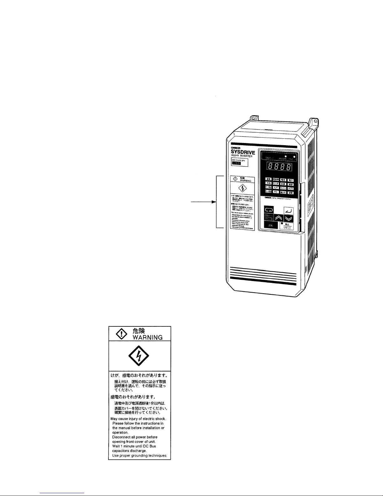
Warning Labels
Warning labels are pasted on the product as shown in the following illustration. Be sure to
follow the instructions given there.
H Warning Labels
Warning
label
H Contents of Warning
Page 10
Checking Before Unpacking
H Checking the Product
On delivery, always check that the delivered product is the SYSDRIVE 3G3HV Inverter that you
ordered.
Should you find any problems with the product, immediately contact your nearest local sales
representative.
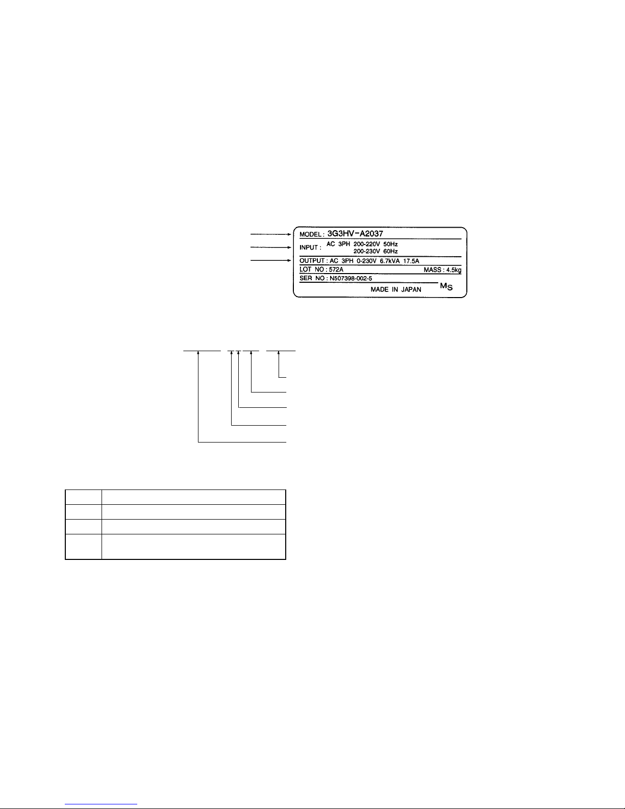
D Checking the Nameplate
Inverter
model
Input specifications
Output specifications
D Checking the Model
3G3HV-A2037-CUE
Applicable standards
Maximum applicable motor capacity
Voltage class
Enclosure rating
Series name: 3G3HV Series
Specification
(non) Japanese models
-E English models
-CE Conforms to EN standards
-CUE Conforms to EN and UL/cUL
standards
Page 11

Maximum Applicable Motor Capacity
037 3.7 kW
055 5.5 kW
075 7.5 kW
110 11 kW
150 15 kW
185 18.5 kW
220 22 kW
300 30 kW
370 37 kW
450 45 kW
550 55 kW
750 75 kW
11K 110 kW
16K 160 kW
18K 185 kW
22K 220 kW
30K 300 kW
Voltage Class
2 Three-phase 200-V AC input (200-V class)
4 Three-phase 400-V AC input (400-V class)
Enclosure Rating
A Panel-mounting (IP10 min.) or closed wall-mounting model
B Panel-mounting (IP00)
D Checking for Damage
Check
the overall appearance and check for damage or scratches resulting from transportation.
Check
that parts connected by screws are securely fastened.
H Checking the Accessories
Note
that this manual is the only accessory provided with the 3G3HV. Set screws and other necessary
parts must be provided by the user.
Page 12

About this Manual
This manual is divided into the chapters described in the following table. Information is organized by
application area to enable you to use the manual more efficiently.
Chapter Contents
Chapter 1 Introduction Describes functions and nomenclature.
Chapter 2 Installation Provides dimensions, installation methods, and wiring methods.
Chapter 3 Preparing for Operation Describes procedures required for preparing the Inverter and Digital
Operator for operation. It is divided into the following areas:
Preparation Procedure
Outlines the procedures required to use the Inverter from purchase
right up to actual operation.
Using the Digital Operator
Describes the nomenclature, operating methods, such as Digital
Operator key operations, and monitor functions.
Test Run
Describes how to perform a test run using the Digital Operator to
confirm operation for the Inverter and the system in which it is to be
used.
Basic Operation
Describes the functions used for the basic control. The functions
described here are the minimum required for running a motor with an
Inverter.
Applied Operation
Describes all the applied functions that are available with the Inverter.
This includes explanations for functions that can be used to improve
the responsiveness (torque characteristic) and the speed accuracy, as
well as additional functions such as PID control and overtorque
detection.
Chapter 4 Operation Provides information related to Inverter maintenance. This includes
possible causes and countermeasures for errors, as well as inspection
procedures.
Chapter 5 Specifications Provides Inverter specifications, as well as the specifications and
dimensions of peripheral devices.
Chapter 6 Appendix Provides notes on using the Inverter on a motor and gives a list of
standard models. It also provides ordered lists of parameters for easy
reference. The parameter lists include page references.
Page 13

Table of Contents
Chapter 1. Introduction .
. . . . . . . . . . . . . . . . . . . . . . . . . . . . . . . . . . . .
1-1 Function . . . . . . . . . . . . . . . . . . . . . . . . . . . . . . . . . . . . . . . . . . . . . . . . . . . . . . . . . . . . . . . . . . .
1-2 Nomenclature . . . . . . . . . . . . . . . . . . . . . . . . . . . . . . . . . . . . . . . . . . . . . . . . . . . . . . . . . . . . . . .
1-3 Additional Functions . . . . . . . . . . . . . . . . . . . . . . . . . . . . . . . . . . . . . . . . . . . . . . . . . . . . . . . . .
Chapter
2. Installation. . . . . . . . . . . . . . . . . . . . . . . . . . . . . . . . . . . . . .
2-1 Mounting . . . . . . . . . . . . . . . . . . . . . . . . . . . . . . . . . . . . . . . . . . . . . . . . . . . . . . . . . . . . . . . . . .
2-1-1 Dimensions . . . . . . . . . . . . . . . . . . . . . . . . . . . . . . . . . . . . . . . . . . . . . . . . . . . . . . . . . .
2-1-2 Installation Conditions . . . . . . . . . . . . . . . . . . . . . . . . . . . . . . . . . . . . . . . . . . . . . . . . .
2-2 Wiring . . . . . . . . . . . . . . . . . . . . . . . . . . . . . . . . . . . . . . . . . . . . . . . . . . . . . . . . . . . . . . . . . . . .
2-2-1 Removing and Mounting the Front Cover . . . . . . . . . . . . . . . . . . . . . . . . . . . . . . . . . .
2-2-2 Terminals . . . . . . . . . . . . . . . . . . . . . . . . . . . . . . . . . . . . . . . . . . . . . . . . . . . . . . . . . . . .
2-2-3 Standard Connection Diagram . . . . . . . . . . . . . . . . . . . . . . . . . . . . . . . . . . . . . . . . . . .
2-2-4 Wiring Around the Main Circuit . . . . . . . . . . . . . . . . . . . . . . . . . . . . . . . . . . . . . . . . .
2-2-5 Wiring Control Circuit Terminals . . . . . . . . . . . . . . . . . . . . . . . . . . . . . . . . . . . . . . . . .
Chapter 3. Pr
eparing for Operation. . . . . . . . . . . . . . . . . . . . . . . . . . .
3-1 Preparation Procedure . . . . . . . . . . . . . . . . . . . . . . . . . . . . . . . . . . . . . . . . . . . . . . . . . . . . . . . .
3-2 Using the Digital Operator . . . . . . . . . . . . . . . . . . . . . . . . . . . . . . . . . . . . . . . . . . . . . . . . . . . .
3-2-1 Nomenclature . . . . . . . . . . . . . . . . . . . . . . . . . . . . . . . . . . . . . . . . . . . . . . . . . . . . . . . .
3-2-2 Summary . . . . . . . . . . . . . . . . . . . . . . . . . . . . . . . . . . . . . . . . . . . . . . . . . . . . . . . . . . . .
3-3 Test Run . . . . . . . . . . . . . . . . . . . . . . . . . . . . . . . . . . . . . . . . . . . . . . . . . . . . . . . . . . . . . . . . . . .
3-4 Basic Operation . . . . . . . . . . . . . . . . . . . . . . . . . . . . . . . . . . . . . . . . . . . . . . . . . . . . . . . . . . . . .
3-5 Applied Operation . . . . . . . . . . . . . . . . . . . . . . . . . . . . . . . . . . . . . . . . . . . . . . . . . . . . . . . . . . .
3-5-1 Energy-saving Mode . . . . . . . . . . . . . . . . . . . . . . . . . . . . . . . . . . . . . . . . . . . . . . . . . . .
3-5-2 PID Control . . . . . . . . . . . . . . . . . . . . . . . . . . . . . . . . . . . . . . . . . . . . . . . . . . . . . . . . . .
3-5-3 List of Parameters . . . . . . . . . . . . . . . . . . . . . . . . . . . . . . . . . . . . . . . . . . . . . . . . . . . . .
3-5-4 Parameters in Detail . . . . . . . . . . . . . . . . . . . . . . . . . . . . . . . . . . . . . . . . . . . . . . . . . . .
Chapter
4. Operation. . . . . . . . . . . . . . . . . . . . . . . . . . . . . . . . . . . . . . .
4-1 Protective and Diagnostic Functions . . . . . . . . . . . . . . . . . . . . . . . . . . . . . . . . . . . . . . . . . . . . .
4-2 Troubleshooting . . . . . . . . . . . . . . . . . . . . . . . . . . . . . . . . . . . . . . . . . . . . . . . . . . . . . . . . . . . . .
4-3 Maintenance and Inspection . . . . . . . . . . . . . . . . . . . . . . . . . . . . . . . . . . . . . . . . . . . . . . . . . . .
Chapter
5. Specifications. . . . . . . . . . . . . . . . . . . . . . . . . . . . . . . . . . . .
5-1 Specifications of Inverters . . . . . . . . . . . . . . . . . . . . . . . . . . . . . . . . . . . . . . . . . . . . . . . . . . . . .
5-2 Specifications of Peripheral Devices . . . . . . . . . . . . . . . . . . . . . . . . . . . . . . . . . . . . . . . . . . . . .
5-2-1 Peripheral Devices . . . . . . . . . . . . . . . . . . . . . . . . . . . . . . . . . . . . . . . . . . . . . . . . . . . .
5-2-2 3G3HV-PCMA2 Voltage/Current Conversion Card . . . . . . . . . . . . . . . . . . . . . . . . . . .
5-2-3 K3TJ-V11j Scaling Meter . . . . . . . . . . . . . . . . . . . . . . . . . . . . . . . . . . . . . . . . . . . . .
5-2-4 3G3IV-PJVOP96j Analog Operator (Standard Model with Steel Casing) . . . . . . . .
5-2-5 3G3IV-PJVOP95j Analog Operator (Miniature Model with Plastic Casing) . . . . . .
5-2-6 3G3IV-PCDBRjB Braking Unit (Yaskawa Electric) . . . . . . . . . . . . . . . . . . . . . . . . .
5-2-7 3G3IV-PLKEBj Braking Resistor Unit . . . . . . . . . . . . . . . . . . . . . . . . . . . . . . . . . . .
5-2-8 3G3HV-PUZDABjAjMH DC Reactor . . . . . . . . . . . . . . . . . . . . . . . . . . . . . . . . . . .
5-2-9 3G3IV-PUZBABjAjMH AC Reactor . . . . . . . . . . . . . . . . . . . . . . . . . . . . . . . . . . . . . .
5-2-10 Simple Input Noise Filter and Input Noise Filter . . . . . . . . . . . . . . . . . . . . . . . . . . . . .
5-2-11 3G3IV-PLFj Output Noise Filter (Tokin Corp.) . . . . . . . . . . . . . . . . . . . . . . . . . . . . .
Page 14

Table of Contents
Chapter
6. Appendix. . . . . . . . . . . . . . . . . . . . . . . . . . . . . . . . . . . . . . . .
6-1 Notes on Using the Inverter for a Motor . . . . . . . . . . . . . . . . . . . . . . . . . . . . . . . . . . . . . . . . . .
6-2 List of Parameters . . . . . . . . . . . . . . . . . . . . . . . . . . . . . . . . . . . . . . . . . . . . . . . . . . . . . . . . . . .
Revision History . . . . . . . . . . . . . . . . . . . . . . . . . . . . . . . . .
Page 15

Chapter 1
Introduction
1-1 Function
1-2 Nomenclature
1-3 Additional Functions
1
Page 16

1-2
1-1 Function
The
3G3HV High-capacity General-purpose Inverter is an easy-to-use inverter that has
advanced features, such as PID control and energy-saving operations.
H SYSDRIVE 3G3HV Inverter Models
• The following 200- and 400-V class 3G3HV Inverter models are available.
• A
total of 21 types of Inverter are available for maximum applicable
motor capacities of 0.4 to 300 kW
.
Voltage class Protective structure Maximum applied motor
capacity
Model
200-V Class
NEMA1 type
3.7 kW 3G3HV-A2037-E
(3-phase)
y
5.5 kW 3G3HV-A2055-E
7.5 kW 3G3HV-A2075-E
11 kW 3G3HV-A2110-E
15 kW 3G3HV-A2150-E
Open chassis type
18.5 kW 3G3HV-B2185-E
y
22 kW 3G3HV-B2220-E
30 kW 3G3HV-B2300-E
37 kW 3G3HV-B2370-E
45 kW 3G3HV-B2450-E
55 kW 3G3HV-B2550-E
75 kW 3G3HV-B2750-E
400-V Class
NEMA1 type
3.7 kW 3G3HV-A4037-E
(3-phase)
y
5.5 kW 3G3HV-A4055-E
7.5 kW 3G3HV-A4075-E
11 kW 3G3HV-A4110-E
15 kW 3G3HV-A4150-E
Open chassis type
18.5 kW 3G3HV-B4185-E
y
22 kW 3G3HV-B4220-E
30 kW 3G3HV-B4300-E
37 kW 3G3HV-B4370-E
45 kW 3G3HV-B4450-E
55 kW 3G3HV-B4550-E
75 kW 3G3HV-B4750-E
110 kW 3G3HV-B411K-E
160 kW 3G3HV-B416K-E
185 kW 3G3HV-B418K-E
220 kW 3G3HV-B422K-E
300 kW 3G3HV-B430K-E
Introduction Chapter 1
Page 17

1-3
H Energy-saving Operation
• The rotation speed of a three-phase induction motor does not decrease when the supply voltage
drops
if the motor has a light load. The 3G3HV Inverter in energy-saving operation automatically de
-
tects
the current consumption of the motor connected to the Inverter
, estimates its load, and drops the
output voltage, thus saving the power consumption of the motor efficiently.
• Use
the auto-tuning function of the Inverter in energy-saving mode to reduce the power consumption
of the motor most efficiently if the ratings of the motor are unknown.
• The Inverter in energy-saving mode is ideal for the following applications.
S Rotation control of fans and blowers
S Flow control of pumps
S Control of machines with variable loads, such as metal-working machines, wood-working ma-
chines, and food-processing machines
S Control of machines that mainly operate with light loads
H PID Control
• The Inverter has a PID control function, thus performing follow-up control with ease.
• Follow-up control is a control method in which the Inverter uses a sensor and senses the rotation
speed of the motor and changes the output frequency to control the rotation speed of the motor.
• Follow-up control can be applied to a variety of control operations.
• PID control is ideal for the following applications.
S Speed control: With a speed sensor, such as a tachometric generator, the Inverter regu-
lates
the rotation speed of the motor regardless of the load of the motor or
synchronizes the rotation speed of the motor with that of another motor.
S Pressure control: With a pressure sensor, the Inverter performs constant pressure control.
S Current control: With a current sensor, the Inverter performs precise current control.
S Temperature control: With
a temperature sensor and fan,
the Inverter performs temperature con
-
trol.
H Frequency Reference
• The
following three types of frequency references
are possible to control the output frequency of the
Inverter.
S Numeric input from the Digital Operator of the Inverter
S Voltage input within a range from 0 to 10 V
S Current input within a range from 4 to 20 mA
The Inverter can use one of the above if it is designated with parameters.
• A
maximum of four frequency references can be registered with the Inverter
. With remote multi-step
input, the Inverter can be in multi-step speed operation with a maximum of four speed steps.
H Frequency Jump
• The
frequency jump function prevents the Inverter from generating any frequency that causes the ma
-
chine to resonate.
Introduction Chapter 1
Page 18

1-4
H Acceleration/Deceleration Time Settings
• The
acceleration time and deceleration time of the Inverter can be set independently within a range of
0.0 to 3,600 s.
• Two
acceleration times and two deceleration times can be
set with the Inverter
, any of which can be
selected with remote output.
H V/f Settings
• Select a V/f pattern out of the 15 V/f patterns preset with the Inverter according to the application.
• An optional V/f pattern can be set with the Inverter.
H Monitor Function
• The following items can be monitored with the Digital Operator.
Frequency
reference, output frequency
, output current, output voltage, DC voltage, output power
,
status of input terminals, inverter status, power interruption error, PROM number, total operating
time, and PID feedback value
H Low Noise (3.7- to 160-kW Models)
• The
output transistor of the Inverter is an IGBT (insulated gate bipolar transistor). Using a sine-wave
PWM method with a high-frequency carrier, the motor does not generate metallic noise.
H High Torque at Low Output Frequency Range
• A
torque rate of 150% can be achieved even in a low
speed range where output frequency is only 3 Hz.
H Automatic Torque Boost
• The
Inverter automatically adjusts the output according to the required torque of the motor that is
rotat
-
ing at constant or accelerative speed, thus ensuring the powerful rotation of the motor.
H Harmonic Countermeasures (3.7- to 160-kW Models)
• DC reactors (optional) can be connected to 3.7- to 15-kW models.
• Models of 18.5- to 160-kW have a built-in DC reactor and also employ 12-pulse rectification, which
suppresses harmonics better than a reactor.
Introduction Chapter 1
Page 19
1-5
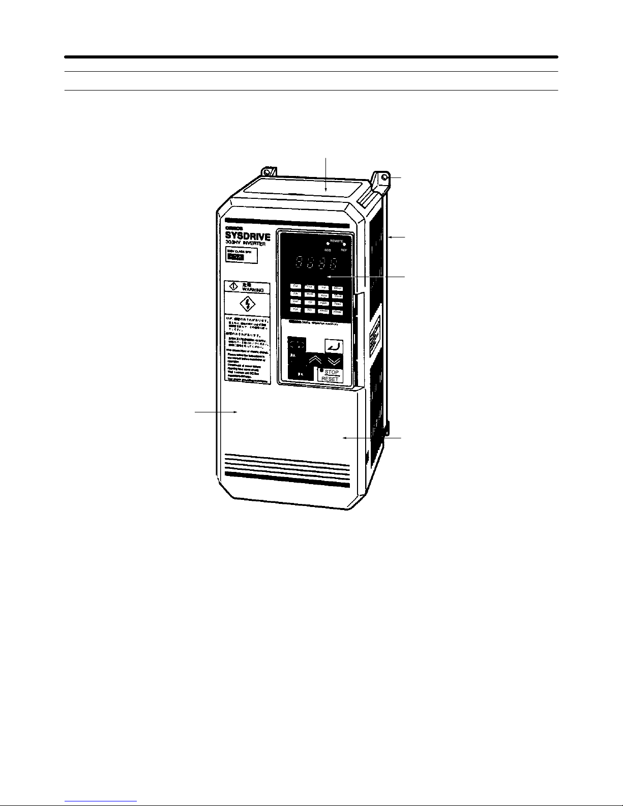
1-2 Nomenclature
H Panel
Protection cover (top and bottom)
Mounting hole
Heat sink
Digital Operator
Front cover
Terminals
Introduction Chapter 1
Page 20
1-6
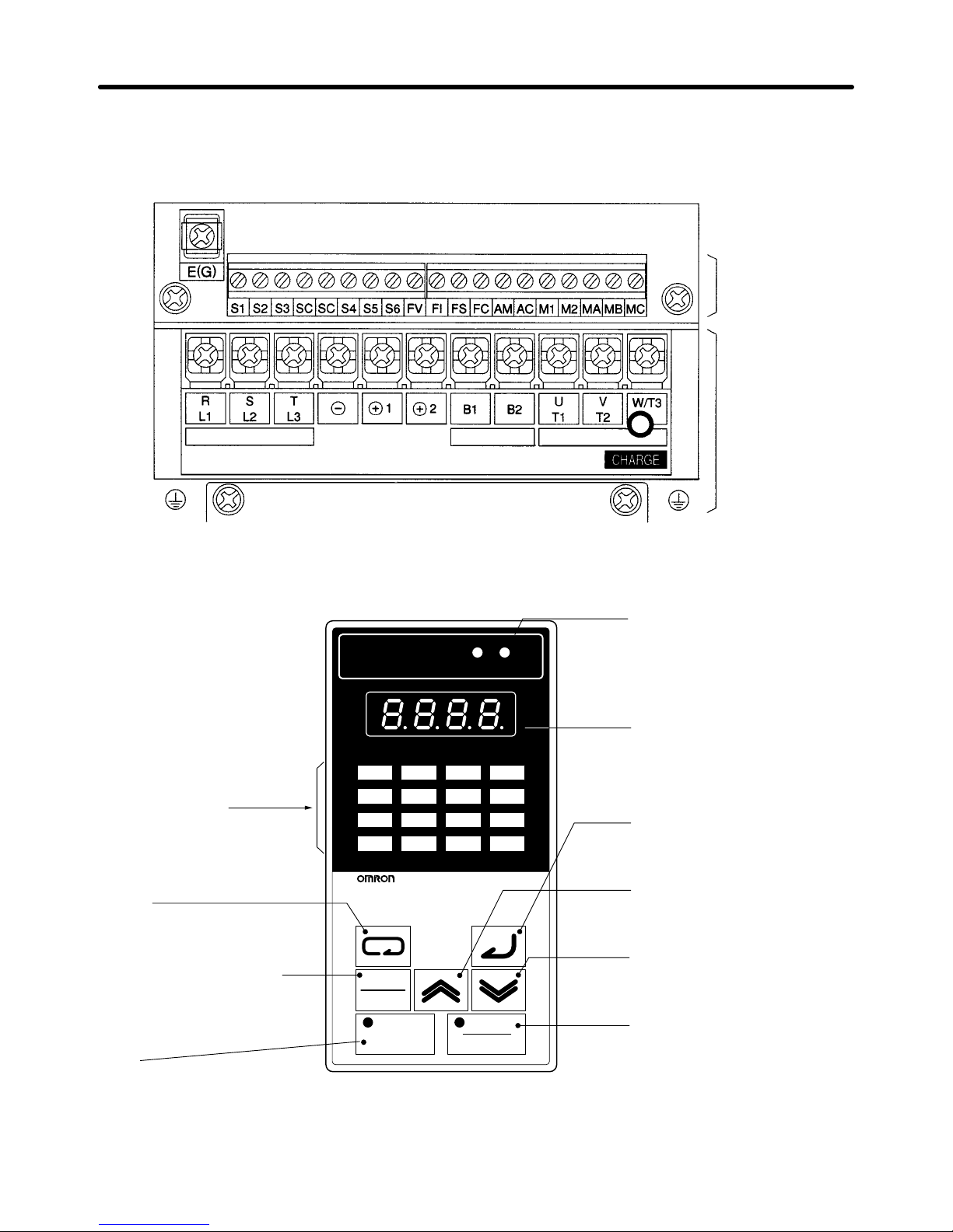
D Terminals (with Front Cover Removed)
Example: 200-V Class Inverter with 3.7-kW Output
Power
input
Braking
Resistor
Motor
output
Control
circuit
terminals
Main circuit
terminals
H Digital Operator
Easy-setting
indicators
Displays basic parameter
constants and monitor items.
Mode Key
Switches basic parameter
constant and monitor items.
Operation Mode Selection Key
Switches between operation by
the Digital Operator and operation
specified in the operation mode
selection parameter (n002).
Run Key
Starts the Inverter
.
Operation Mode Indicators
External Operation:
Lit when operating references from exter
-
nal terminals are in ef
fect.
Analog Input:
Lit when high-frequency references from
external analog terminals are in ef
fect.
Data Display
Displays frequency reference, out
-
put frequency
, output current,
constant set values, Inverter status,
etc.
Enter Key
Enters set value when pressed after
constant has been set.
Increment Key
Increments numbers when pressed
during setting of constant number
and constant data.
Decrement Key
Decrements numbers when
pressed during setting of constant
number and constant data.
Stop/Reset Key
Stops the Inverter
. Also resets after
alarm has been generated. (See note.)
DIGITAL OPERATOR PJVOP131E
Fref Fout Iout kWout
F/R Montr Accel Decel
Vmtr V/F Fgain Fbias
FLA PID kWsav PRGM
LOCAL
REMOTE
RUN
STOP
RESET
REMOTE
SEQ REF
Note For
safety reasons, the reset function cannot be
used while the run command (forward/reverse) is
being input. Turn the run command OFF before using the reset function.
Introduction Chapter 1
Page 21

1-7
1-3 Additional Functions
New functions have been added to the following versions, for which production was
started in April 1997.
3.7 to 15-kW models: Software version S2011 (VSP102011) or later
18.5 to 55-kW models: Software version S3012 (VSP103012) or later
Note:
The software version can be confirmed by viewing the 4-digit PROM number with
the monitor function. This number is set to the number of the software version.
The
functions that have been added with these versions and outlines of these functions
are given below. For details of the functions, refer to
Section 4 Operation
.
H Independent Initialization for Motor Rotation Direction
Although
the functionality of the forward/reverse rotation selection parameter (n005) itself has not been
changed,
with new models it will not be initialized when the parameter write prohibit selection/parame
-
ter initialization parameter (n001) is set to 6 or 7.
H V/f Default Settings Changed (Inverters of 55 kW or More)
The
default settings for V/f patterns have been changed for
the Inverters of 55 kW or more as shown
below.
Model Intermediate output frequency
voltage (n016)
Minimum output frequency
voltage (n018)
3G3HV-A2550 12.0 V 6.0 V
3G3HV-A4550 24.0 V 12.0 V
H Output Frequency Upper Limit Changed
The upper limit of the setting range for the output frequency upper limit parameter (n030) has been
changed.
The addition of a slip compensation function means that frequencies greater than the maxi
mum frequency (n012) may occur (because the frequency reference is added to the compensation
value).
For this reason, the upper limit of the setting range of the output frequency upper limit parameter
(n030) has been increased from 100% to 109%.
H PID Input Characteristic Selection Function (n039)
A
PID input characteristic selection input (set value: 27) function has been added to the multi-function
input 5 parameter (n039) that determines the function of terminal S6.
H Carrier Frequency Settings Increased (n050)
The setting 7.0 Hz (set value: 10) has been added to the available carrier frequency settings.
H Minimum Baseblock Time Setting Range Increased (n053)
The
setting range for the minimum baseblock time has been increased from the range 0.5 to 5.0 s to the
range 0.5 to10.0 s for increased motor responsiveness.
H Slip Compensation Function (n109 to n111)
A
function that compensates for motor slip, a characteristic of induction motors, has been added. Using
this
function, the amount of slip is estimated
from the output current of the Inverter
, and the output fre
-
Introduction Chapter 1
Page 22

1-8
quency
is compensated accordingly
. By using the slip compensation function, speed fluctuations of the
load can be reduced more effectively than with previous models.
H Changing Parameters while Inverter is Running
It
is now possible to change some
parameters and, related to this, monitor and set the items in the bot
tom
two lines of
easy-setting indicators while the Inverter is running. Using this feature, set values for
some
parameters can be adjusted while monitoring operation. For details of which parameters can be
changed while the Inverter is running, refer to the parameter lists.
H Operation Selection at Digital Operator Interruption Function (n112)
A
function that detects communications errors between the Digital Operator and the Inverter itself, and
interrupts Inverter outputs has been added.
H Settable Detection Width (n113)
The
detection width of the optional frequency agreement and
the optical frequency detection can be set
with parameters. With previous models this setting was fixed.
H Operation Selection at Operation Mode Switching (Local/Remote
Switching) (n114)
Using
the Operation Mode Selection Key on the Digital Operator or operation mode selection input set
using the multi-function input parameters (set value: 5), it is possible to switch between operation from
the
Digital Operator and operation according
to the setting of the operation mode selection parameter
(n002). A function that selects whether run signals input while the operation mode is switching are
enabled or disabled after the mode has changed, has been added.
Note If
this setting is set to enable run commands, when the operation mode changes the Inverter will
start running immediately. Take steps to ensure safety for such operation.
Introduction Chapter 1
Page 23

Chapter 2
Installation
2-1 Mounting
2-2 Wiring
2
Page 24
2-2
2-1 Mounting
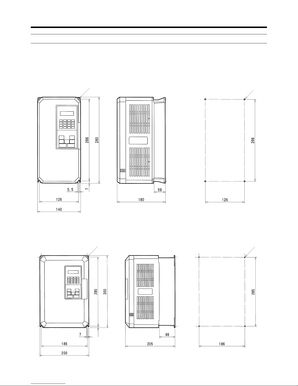
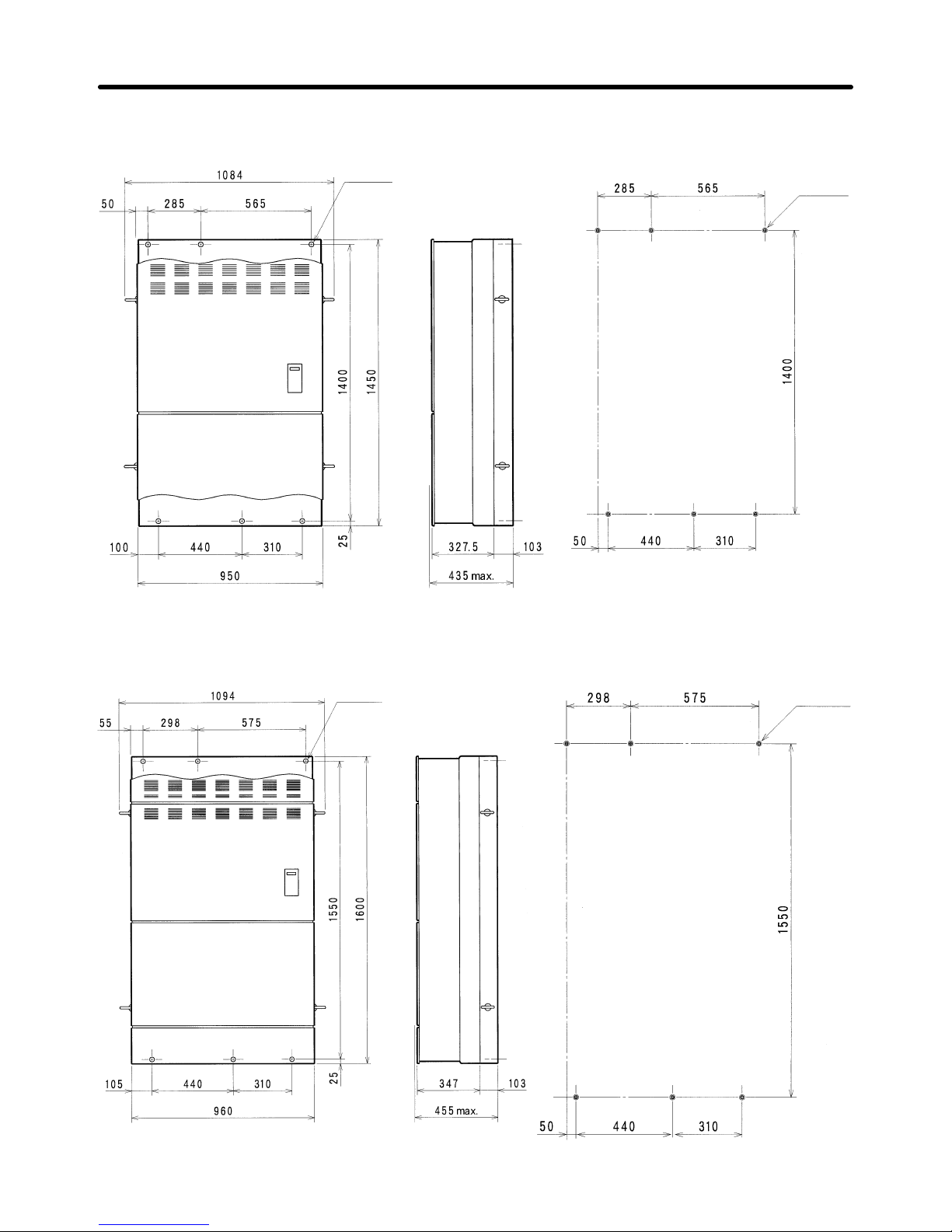
2-1-1 Dimensions
H 3G3HV-A2037/-A4037
D External Dimensions D Mounting Dimensions
Two,
5.5-dia.
Four, M5
H 3G3HV-A2055/-A2075/-A4055/-A4075
8
D External Dimensions D Mounting Dimensions
Two,
7-dia.
Four, M5
Installation Chapter 2
Page 25
2-3
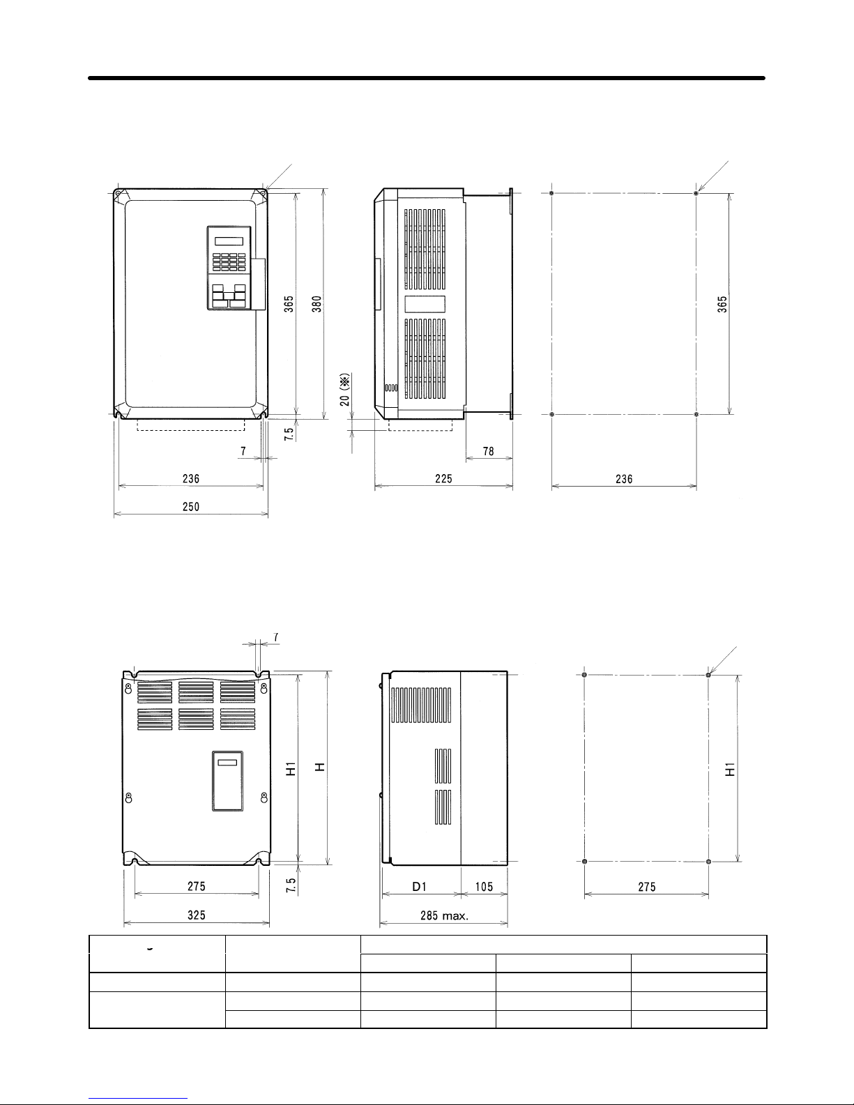
H 3G3HV-A2110/-A2150/-A4110/-A4150
D External Dimensions D Mounting Dimensions
Two,
7-dia.
Four, M5
Note *The dashed lines apply only to the A2150.
H 3G3HV-B2185/-B2220/-B4185/-B4220/-B4300/-B4450
D External Dimensions D Mounting Dimensions
Four, M5
Voltage class
Model 3G3HV-
Dimensions (mm)
g
H H1 D1
200-V B2185/B2220 450 435 174.5
400-V
B4185/B4220 450 435 174.5
B4300/B4370/B4450 526 610 175
Installation Chapter 2
Page 26
2-4
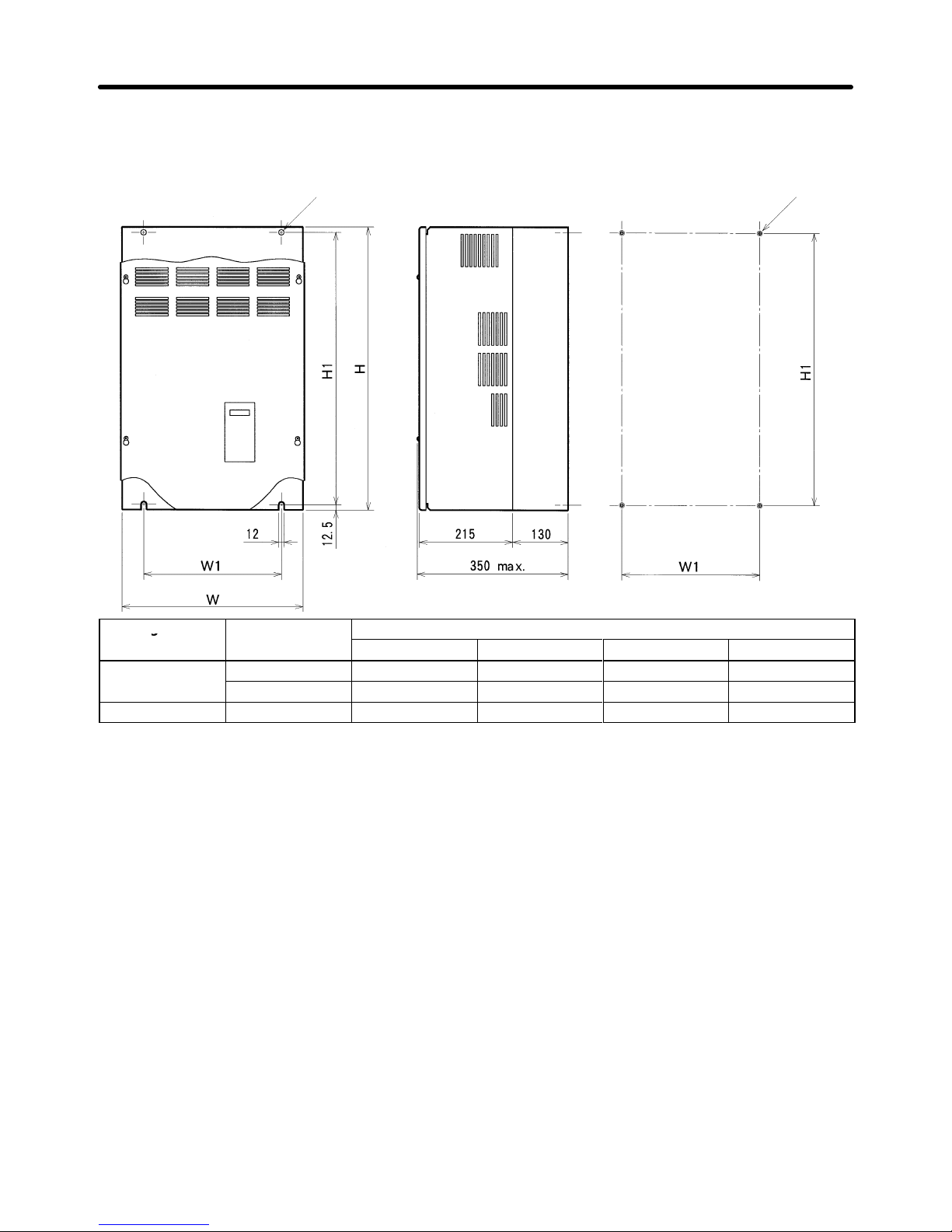
H 3G3HV-B2300/-B2370/-B2450/-B2550/-B4550/-B4750
D External Dimensions D Mounting Dimensions
Two,
12-dia.
Four
, M10
Voltage class Model 3G3HV-
Dimensions (mm)
g
W H W1 H1
200-V
B2300/B2370 425 675 320 650
B2450/B2550 475 800 370 775
400-V B4550/B4750 455 820 350 795
Installation Chapter 2
Page 27
2-5
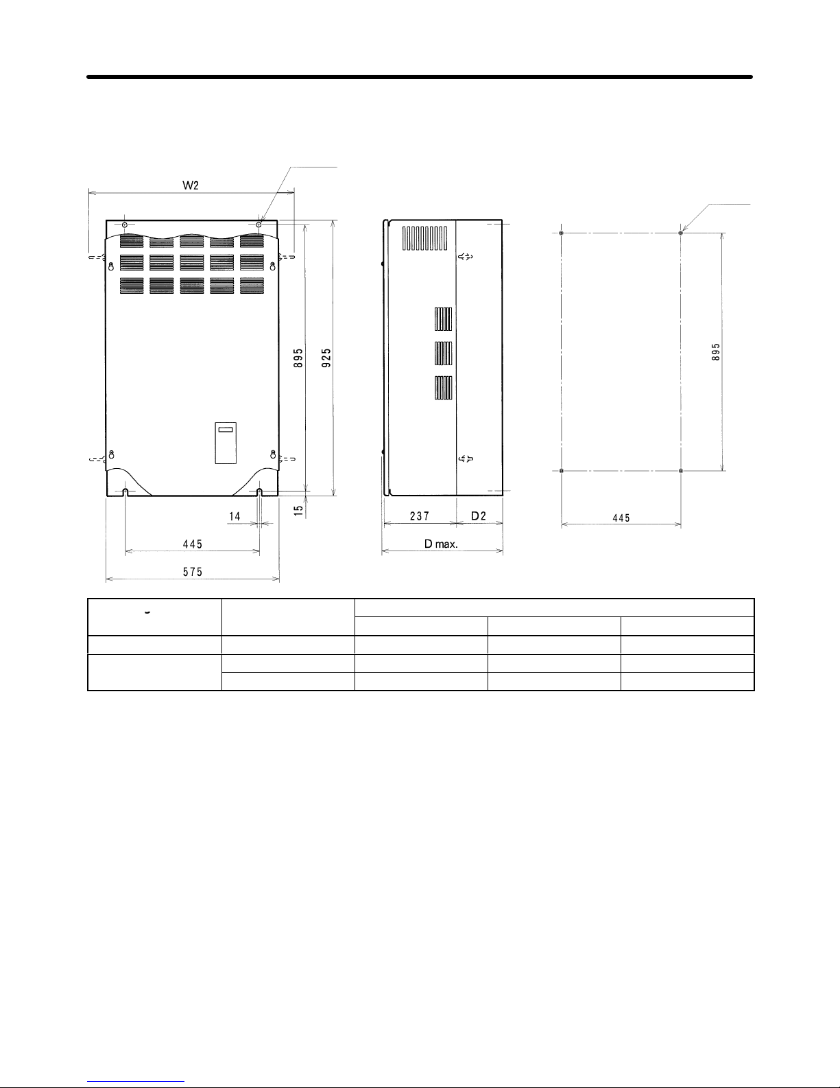
H 3G3HV-B2750/-B411K/-B416K
Two,
14 dia.
Four
, M12
D External Dimensions D Mounting Dimensions
Voltage
class
Model 3G3HV-
Dimensions (mm)
g
D D2 W2
200-V B2750 400 max. 158 695
400-V
B411K 375 max. 130 695
B416K 400 max. 158 695
Installation Chapter 2
Page 28
2-6
H 3G3HV-B418K/-B422K
Six,
14 dia.
Six, M12
D External Dimensions D Mounting Dimensions
H 3G3HV-B430K
D External Dimensions D Mounting Dimensions
Six,
14 dia.
Six, M12
Installation Chapter 2
Page 29
!
!
!
!
!
2-7
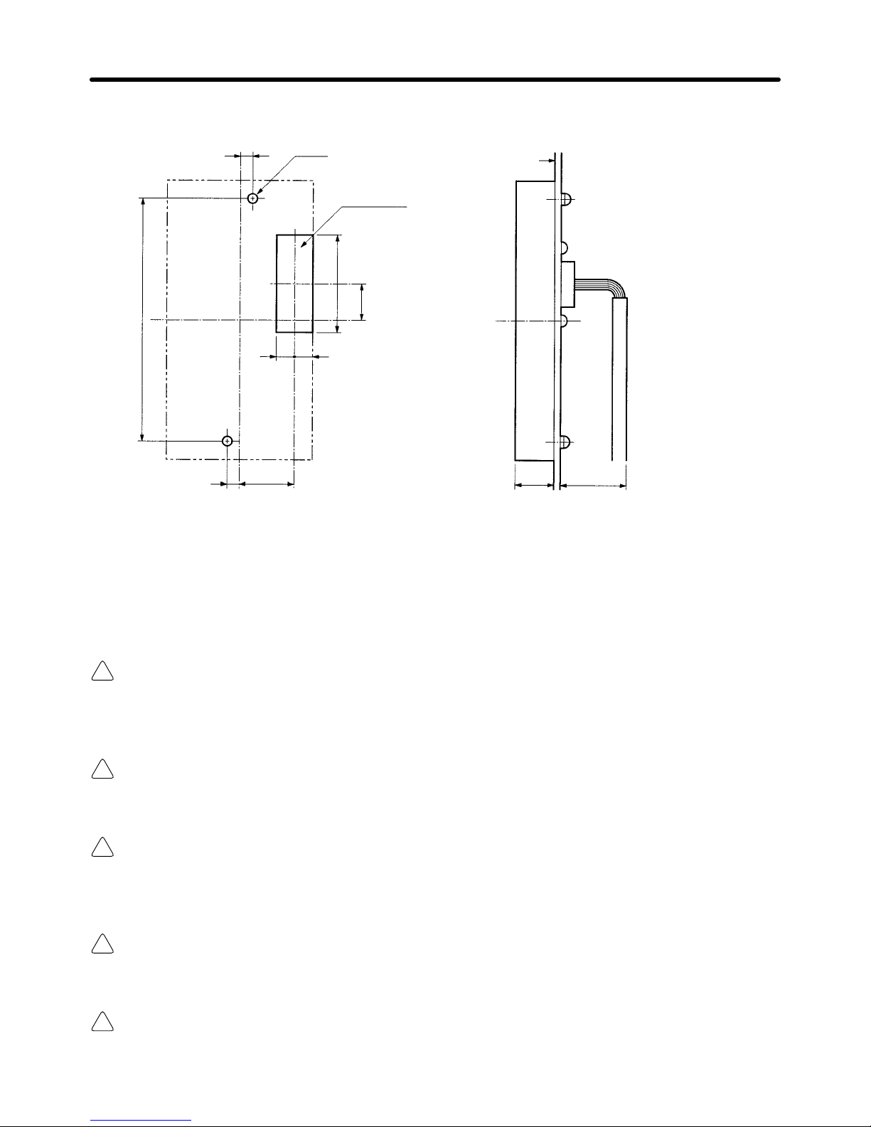
D Digital Operator Installation
Panel cutout
(for cables)
Two, 4 dia.
Panel face
Front side of panel
Back side of panel
30 min.
4
125
4
27
88
16
39
18.8
2-1-2 Installation Conditions
H Cautions and Warnings
WARNING Provide an appropriate stopping device on the machine side to secure safety. (A
holding
brake is
not a stopping device for securing safety
.) Not doing so may result in
injury.
WARNING Provide
an external emergency stopping device that
allows an instantaneous stop of
operation and power interruption. Not doing so may result in injury.
Caution Be sure to install the product in the correct direction and provide specified clear-
ances between the Inverter and control panel or with other devices. Not doing so
may result in fire or malfunction.
Caution Do
not allow foreign objects to
enter inside the product. Doing so may result in fire or
malfunction.
Caution Do not apply any strong impact. Doing so may result in damage to the product or
malfunction.
Installation Chapter 2
Page 30
2-8
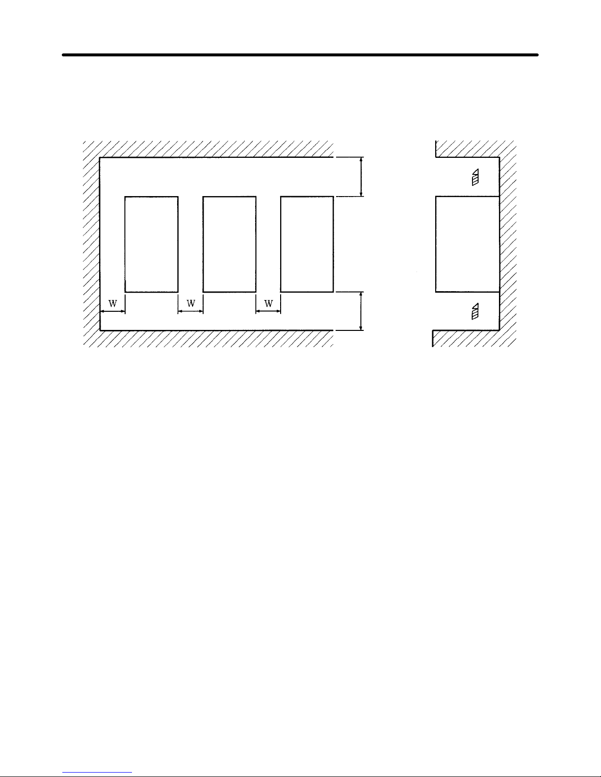
H Direction and Space
• Install
the Inverter on a vertical surface so that the characters on the nameplate are oriented upward.
• When
installing the Inverter
, always provide the following installation space to allow normal heat dis
-
sipation from the Inverter.
W = 30 mm min.
Inverter Inverter Inverter
120 mm min.
120 mm min.
Air
Side
Air
H Installation Site
• Install the Inverter under the following conditions.
NEMA1 Type
Ambient temperature for operation: –10 to 40°C
Humidity: 90% RH or less (no condensation)
Open Chassis Type
Ambient temperature for operation: –10 to 45°C
Humidity: 90% RH or less (no condensation)
Note A
protection cover is attached to the top and bottom of the Inverter
. Be sure to remove the protec
-
tion
covers before installing the 200- or 400-V Class Inverter that has an output of 15 kW or less to
a panel.
• Install
the Inverter in a clean location free from oil mist and dust. Alternatively
, install it in a totally en
-
closed panel that is completely shielded from floating dust.
• When
installing or operating the Inverter, always take special care so that metal powder
, oil, water
, or
other foreign matter does not get into the Inverter.
• Do not install the Inverter on inflammable material such as wood.
H Ambient Temperature Control
• To
enhance operation reliability
, the Inverter should be installed in an environment free from extreme
temperature rises.
• If
the Inverter is installed in an enclosed environment such as a box, use a cooling fan or air conditioner
to maintain the internal air temperature below 45°C.
Installation Chapter 2
Page 31

2-9
H Protecting Inverter from Foreign Matter during Installation
• Place a cover over the Inverter during installation
to shield it from metal power produced by drilling.
• Upon
completion of installation, always remove the cover from the Inverter
. Otherwise, ventilation will
be affected, causing the Inverter to overheat.
Installation Chapter 2
Page 32

!
!
!
!
!
!
!
!
!
!
2-10
2-2 Wiring
WARNING Wiring must be performed only after confirming that the power supply has been
turned OFF. Not doing so may result in electrical shock.
WARNING Wiring must be performed by authorized personnel. Not doing so may result in
electrical shock or fire.
WARNING Be
sure to confirm operation only after wiring the emergency stop circuit. Not doing
so may result in injury.
WARNING Always
connect the ground terminals to a ground of 100 Ω or less for
the 200-V AC
class,
or 10 Ω or less for the 400-V AC class. Not connecting to a
proper ground may
result in electrical shock.
Caution Install
external breakers and take other safety measures
against short-circuiting in
external wiring. Not doing so may result in fire.
Caution Confirm
that the rated input voltage of the Inverter is the same as the AC power sup
-
ply voltage. An incorrect power supply may result in fire, injury, or malfunction.
Caution Connect
the Braking Resistor and Braking Resistor Unit as specified
in the manual.
Not doing so may result in fire.
Caution Be
sure to wire correctly and securely
. Not doing so may result
in injury or damage to
the product.
Caution Be
sure to firmly tighten the screws on the terminal block. Not doing so may result in
fire, injury, or damage to the product.
Caution Do
not connect an AC power to the U, V
, or W output. Doing
so may result in damage
to the product or malfunction.
Installation Chapter 2
Page 33

2-11
2-2-1 Removing and Mounting the Front Cover
Remove
the front cover
to wire the terminals. Remove the Digital Operator from the front
cover
before removing the front cover
. Do not remove or mount the front cover without
first removing the Digital Operator, otherwise Digital Operator may malfunction due to
imperfect contact.
H Removing the Digital Operator
• Press
the lever on the side of the Digital Operator in the arrow 1 direction to unlock the Digital Opera
-
tor and lift the Digital Operator in the arrow 2 direction to remove the Digital Operator as shown in the
following illustration.
H Removing the Front Cover
• Press
the left and right sides of the front cover in
the arrow 1 directions and lift the bottom of the cover
in the arrow 2 direction to remove the front cover as shown in the following illustration.
Installation Chapter 2
Page 34

2-12
H Mounting the Front Cover
• Mount
the front cover to the Inverter
by taking in reverse order to the steps to remove the front cover
after wiring the terminals.
• Do not mount the front cover with the Digital Operator attached to the front cover, otherwise Digital
Operator may malfunction due to imperfect contact.
• Insert
the tab of the
upper part of the front cover into the groove of the Inverter and press the lower part
of the front cover onto the Inverter until the front cover snaps shut.
H Attaching the Digital Operator
• Hook
the Digital Operator on clicks A of the front cover in the arrow 1 direction as shown
in the follow
-
ing illustration.
• Press the Digital Operator in the arrow
2
direction until it snaps shut with clicks B.
Clicks A
Clicks B
Note Do
not remove or attach the
Digital Operator or mount or remove the front cover using methods
other
than those mentioned above, otherwise the Inverter may malfunction due to imperfect con
-
tact or break.
H Removing the Front Cover of the Inverter with 18.5-kW Output or More
• The
front cover can be removed without removing the Digital Operator from the Inverter provided that
the Inverter is a model with an output of 18.5 kW or more.
• Loosen
the four screws of the front cover and move the front cover slightly upwards to remove the front
cover.
Installation Chapter 2
Page 35

2-13
2-2-2 Terminals
H Terminal Block Configuration (200-V Class with 3.7-kW Output)
Power
input
Braking
Resistor
Motor
output
Control
circuit
terminals
Main circuit
terminals
H Main Circuit Terminals
D 200-V Class
Model 3G3HV- A2037 to A2075 A2110 to A2150 B2185 to B2750
Maximum
applied motor
capacity
3.7 to 7.5 kW 11 to 15 kW 18.5 to 75 kW
L1 (R)
Power supply input terminals, 3-phase, 200 to 230 VAC,
Power supply input
L2 (S)
y,, ,
50/60 Hz
y
terminals, 3-phase, 200 to
L3 (T)
230 VAC, 50/60 Hz
L11 (R1)
--L21 (S1)
L31 (T1)
T1 (U)
Motor output terminals, 3-phase, 200 to 230 VAC (correspond to input voltage)
T2 (V)
,, ( g)
T3 (W)
B1
Braking Resistor Unit
---
B2
g
connection terminals
1
+
DC reactor connection
-
DC reactor connection
-
---
2
+
terminal ( 1-2)
DC power supply input
+ +
terminal ( 1-2)
DC power supply input
+ +
–
DC ower su ly in ut
terminal ( 1- )
+ –
DC ower su ly in ut
terminal ( 1- )
+ –
3
+
---
BrakingUnit
connection
terminal ( 3- )
+ –
Ground the terminal at a resistance of less than 100 Ω.
Installation Chapter 2
Page 36

2-14
D 400-V Class
Model 3G3HV- A4037 to A4150 B4185 to B416K B418K to B430K
Maximum
applied motor
capacity
3.7 to 15 kW 18.5 to 160 kW 185 to 300 kW
L1 (R)
Power supply input Power supply input Power supply input
L2 (S)
y
terminals, 3-phase, 380 to
y
terminals, 3-phase, 380 to
y
terminals, 3-phase, 380 to
L3 (T)
460 VAC, 50/60 Hz 460 VAC, 50/60 Hz 460 VAC, 50/60 Hz
L11 (R1)
--- --L21 (S1)
L31 (T1)
T1 (U)
Motor output terminals, 3-phase, 380 to 460 VAC (correspond to input voltage)
T2 (V)
,, ( g)
T3 (W)
B1
Braking Resistor Unit
---
B2
g
connection terminals
1
+
DC reactor connection
terminal ( 1- 2)
+ +
---
DC power supply input
terminal ( 1- )
+ –
2
+
()
DC power supply input
---
–
terminal ( 1- )
+ –
Braking Unit connection
3
+
---
terminal ( 3- )
+ –
Ground the terminal at a resistance of less than 10 Ω.
Installation Chapter 2
Page 37

2-15
H Control Circuit Terminals for All 3G3HV Models
Symbol Name Function Signal
level
Input
S1 Forward run/Stop Stops at OFF.
Photocoupler
S2 Multi-function input 1 (S2) Set by constant n035 (reverse run/stop).
24 VDC, 8 mA
S3 Multi-function input 2 (S3) Set by constant n036 (external error a).
S4 Multi-function input 3 (S4) Set by constant n037 (error reset).
S5 Multi-function input 4 (S5) Set by constant n038 (multi-step speed
reference 1).
S6 Multi-function input 5 (S6) Set by constant n039 (multi-step speed
reference 2).
SC Sequence input common Common for S1 to S6.
FS Frequency reference power supply DC power supply for frequency reference. 15 VDC, 20 mA
FV Frequency reference input (voltage) Voltage input terminal for frequency refer-
ence.
0 to 10 VDC (Input impedance:
20 kΩ)
FI Frequency reference input (current) Current input terminal for frequency refer-
ence.
4 to 20 mA (Input impedance:
250 kΩ)
FC Frequency reference input common Common for FV, F1. --E
(G)
Shielded wire connection ground Shielded terminal for sequence and fre-
quency reference inputs. (see note 2)
---
Output
MA Multi-function contact output 1 (normally
open)
Set by constant n040 (error) Contact output
30 VDC, 1 A
MB Multi-function contact output 1 (normally
closed)
,
max.
250 VAC, 1 A
MC Multi-function contact output 1 common Common for MA, MB
max.
M1 Multi-function contact output 2 (normally
open)
Set by constant n041 (running)
M2 Multi-function contact output 2 common Common for M1
AM
Multi-function analog output
Set by constant n048 (output frequency)
0 to 10 VDC,
AC Multi-function analog output common Common for AM
,
2 mA
Note 1. Parameter
settings can be used
to select various functions for multi-function inputs 1 to 5 and
the multi-function contact output.
The functions in parentheses are the default settings.
Note 2. Do not connect a grounding wire to the E (G) terminal. Connect the grounding wire to the
ground terminal of the main circuit terminals.
Installation Chapter 2
Page 38

2-16
2-2-3 Standard Connection Diagram
D For Inverter Models of 200- to 400-V Class with 3.7- to 15-kW Output
Three-phase,
200 (400) VAC
DC reactor (External
connection possible)
Forward rotation/Stop
Multi-function
input
1
Multi-function
input 2
Multi-function
input 4
Multi-function
input 5
Multi-function
input 3
Common
Shielded wire
Variable resistor for
frequency reference
(voltage input)
(2 kΩ, 1/4 W min.)
Frequency
reference
(current input)
Note: These terminals of the 3G3HV-A2110 and 3G3HV-A2150
connect to the Braking Unit and Braking Resistor Unit.
Braking Resistor Unit
(see note) (optional)
Three-phase induction
motor
Multi-function contact output 1
(Normally open contact)
(Normally closed contact)
Common
Common
Multi-function contact output 2
Common
Multi-function analog output
Voltmeter
L1 (R)
L2 (S)
L3 (T)
T1 (U)
T2 (V)
T3 (W)
D Example of Wiring for 3-wire Sequential Operation
Stop switch
(NC)
Operation switch
(NO)
Run command (Operates when the
operation switch is closed)
Stop command (Stops when the stop
switch is open)
Forward/Reverse rotation command
Installation Chapter 2
Page 39

2-17
D For Inverter Models of 200- to 400-V Class with 18.5- to 300-kW Output
Three-phase,
200 (400) VAC
Forward rotation/Stop
Multi-function
input
1
Multi-function
input 2
Multi-function
input 4
Multi-function
input 5
Multi-function
input 3
Common
Shielded wire
Variable resistor for
frequency reference
(voltage input)
Frequency
reference
(current input)
Note 1. The Braking Unit or Braking Resistor Unit cannot be connected to the Inverter
(18.5 kW to 160 kW). However, 185-kW to 300-kW models can be connected.
Note 2. Make sure that terminals R and R1, S and S1, and T and T1 are short-circuited.
These terminals are short-circuited
with short bars before shipping. Be sure to re
-
move the short bars, however, when using 12-pulse rectification.
Note 3. Terminals
L1
1 (R1), L21 (S1), and L31 (T1) are not available on the 185- to 300-kW
Inverters.
Note 4. The
185- to 300-kW Inverters do not have built-in DC
reactors, nor can DC reactors
be externally connected.
Three-phase induction
motor
Multi-function contact output 1
(Normally open contact)
(Normally closed contact)
Common
Common
Multi-function contact output 2
Common
Multi-function analog output
Voltmeter
L1 (R)
L2 (S)
L3 (T)
T1 (U)
T2 (V)
T3 (W)
L1
1 (R1)
L21 (S1)
L31 (T1)
See note 3
D Example of Wiring for 3-wire Sequential Operation
Stop switch
(NC)
Operation switch
(NO)
Run command (Operates when the
operation switch is closed)
Stop command (Stops when the stop
switch is open)
Forward/Reverse rotation command
Installation Chapter 2
Page 40

2-18
2-2-4 Wiring Around the Main Circuit
System
reliability
and noise resistance are af
fected by the wiring method used. There
-
fore,
always follow the instructions given below when connecting the Inverter to periph
-
eral devices and other parts.
H Wire Size and Round Solderless Terminal
For the main circuit and ground, always use 600-V polyvinyl chloride (PVC) cables.
If
the cable is long and may cause voltage drops, increase the wire size
according to the cable length.
D Wire Sizes
Voltage class Model Terminal Terminal
screw
Wire
thickness
(mm2)
200-V Class 3G3HV-A2037
L1, L2, L3, (–), (+)1, (+)2, B1, B2, T1, T2, T3
M4 5.5
3G3HV-A2055
L1, L2, L3, (–), (+)1, (+)2, B1, B2, T1, T2, T3
M5
8
5.5 to 8
3G3HV-A2075
L1, L2, L3, (–), (+)1, (+)2, B1, B2, T1, T2, T3
M5
8
5.5 to 8
3G3HV-A2110
L1, L2, L3, (–), (+)1, (+)2, (+)3, T1, T2, T3
M6
22
8
3G3HV-A2150
L1, L2, L3, (–), (+)1, (+)2, (+)3, T1, T2, T3 M8 30
M6 8
3G3HV-B2185
L1, L2, L3, L11, L21, L31, T1, T2, T3
M8
30
14
3G3HV-B2220
L1, L2, L3, L11, L21, L31, T1, T2, T3
M8
38
14
3G3HV-B2300
L1, L2, L3, L11, L21, L31, T1, T2, T3 M10 100
M8 22
3G3HV-B2370
L1, L2, L3, L11, L21, L31, T1, T2, T3 M10 60 x 2P
M8 22
3G3HV-B2450
L1, L2, L3, L11, L21, L31, T1, T2, T3 M10 60 x 2P
M8 22
3G3HV-B2550
L1, L2, L3, L11, L21, L31, T1, T2, T3 M10 60 x 2P
M8 30
3G3HV-B2750
L1, L2, L3, L11, L21, L31, T1, T2, T3 M12 100 x 2P
M8 50
Installation Chapter 2
Page 41

2-19
Voltage class Model Terminal Terminal
screw
Wire
thickness
(mm
2
)
400-V Class 3G3HV-A4037
L1, L2, L3, (–), (+)1, (+)2, B1, B2, T1, T2, T3
M4
2 to 5.5
3.5 to 5.5
3G3HV-A4055
L1, L2, L3, (–), (+)1, (+)2, B1, B2, T1, T2, T3
M4 3.5 to 5.5
3G3HV-A4075
L1, L2, L3, (–), (+)1, (+)2, B1, B2, T1, T2, T3
M4 5.5
3G3HV-A4110
L1, L2, L3, (–), (+)1, (+)2, B1, B2, T1, T2, T3 M5 8 to 14
M6 8
3G3HV-A4150
L1, L2, L3, (–), (+)1, (+)2, B1, B2, T1, T2, T3 M5 8 to 14
M6 8
3G3HV-B4185
L1, L2, L3, L11, L21, L31, T1, T2, T3 M6 14
M8 8
400-V Class 3G3HV-B4220
L1, L2, L3, L11, L21, L31, T1, T2, T3 M6 22
M8 8
3G3HV-B4300
L1, L2, L3, L11, L21, L31, T1, T2, T3
M8
22
8
3G3HV-B4370
L1, L2, L3, L11, L21, L31, T1, T2, T3
M8
30
14
3G3HV-B4450
L1, L2, L3, L11, L21, L31, T1, T2, T3
M8
50
14
3G3HV-B4550
L1, L2, L3, L11, L21, L31, T1, T2, T3 M10 100
M8 22
3G3HV-B4750
L1, L2, L3, L11, L21, L31, T1, T2, T3 M10 60 x 2P
M8 22
3G3HV-B411K
L1, L2, L3, L11, L21, L31, T1, T2, T3 M10 60 x 2P
M8 30
3G3HV-B416K
L1, L2, L3, L11, L21, L31, T1, T2, T3 M12 100 x 2P
M8 50
3G3HV-B418K
L1, L2, L3, (–), (+)1, (+)3, T1, T2, T3 M16 325 x 2P
M8 50
3G3HV-B422K
L1, L2, L3, (–), (+)1, (+)3, T1, T2, T3 M16 325 x 2P
M8 60
3G3HV-B430K
L1, L2, L3, (–), (+)1, (+)3, T1, T2, T3 M16 325 x 2P
M8 60
Note The wire thickness is set for copper wires at 75°C.
Installation Chapter 2
Page 42

2-20
D Round Solderless Terminals and Tightening Torque
Wire thickness
(mm
2
)
Terminal
screw
Size Tightening
torque (NSm)
0.5 M4 1.25 – 4 1.2
0.75 M4 1.25 – 4 1.2
1.25 M4 1.25 – 4 1.2
2
M4 2 – 4 1.2
M5 2 – 5 2.0
M6 2 – 6 2.5
M8 2 – 8 6.0
3.5/5.5
M4 5.5 – 4 1.2
M5 5.5 – 5 2.0
M6 5.5 – 6 2.5
M8 5.5 – 8 6.0
8
M5 8 – 5 2.0
M6 8 – 6 2.5
M8 8 – 8 6.0
14
M6 14 – 6 2.5
M8 14 – 8 6.0
22
M6 22 – 6 2.5
M8 22 – 8 6.0
30/38 M8 38 – 8 6.0
50/60
M8 60 – 8 6.0
M10 60 – 10 10.0
80
M10
80 – 10 10.0
100 100 – 10 10.0
100
M12
100 – 12 14.0
150 150 – 12 14.0
200 200 – 12 14.0
325
M12 x 2 325 – 12 14.0
M16 325 – 16 25.0
Note Determining Wire Size
Determine
the wire size for
the main circuit so that line voltage drop is within 2% of the rated volt
-
age.
Line voltage drop is calculated as follows:
Line voltage drop (V) = √3 x wire resistance (Ω/km) x wire length (m) x current (A) x 10
–3
Installation Chapter 2
Page 43

2-21
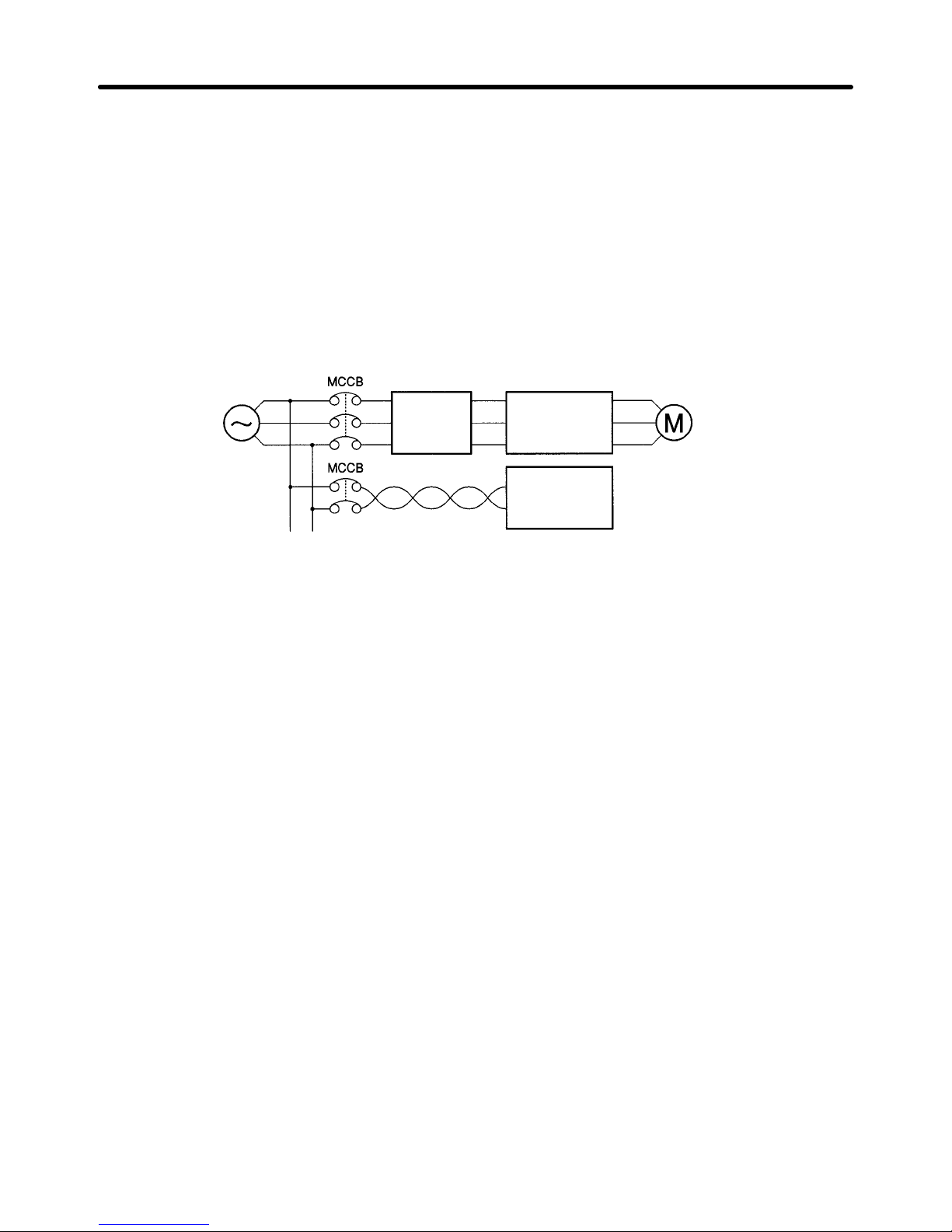
H Wiring on the Input Side of the Main Circuit
D Installing a Molded-case Circuit Breaker
Always
connect
the power input terminals (R/L1, S/L2, and T/L3) and power supply via a molded case
circuit breaker (MCCB) suitable to the Inverter.
• Install one wiring circuit breaker per Inverter.
• Choose an MCCB with a capacity of 1.5 to 2 times the Inverter’s rated current.
• For
the MCCB’
s time characteristics, be sure to consider the Inverter’s overload protection (one min
-
ute at 150% of the rated output current).
• If
the MCCB is
to be used in common among multiple Inverters, or other devices, set up a sequence
such that the power supply will be turned OFF by a fault output, as shown in the following diagram.
3-phase/
Single-phase
200 V AC
3-phase
400 V AC
Power
supply
Inverter
Fault output (NC)
(See note.)
Note Use a 400/200 V transformer for a 400-V model.
D Installing a Ground Fault Interrupter
Inverter outputs use high-speed switching, so high-frequency leakage current is generated.
In general, a leakage current of approximately 100 mA will occur for each Inverter (when the power
cable is 1 m) and approximately 5 mA for each additional meter of power cable.
Therefore,
at the power supply input area, use
a special-purpose breaker for Inverters, which detects
only the leakage current in the frequency range that is hazardous to humans and excludes high-frequency leakage current.
• For the special-purpose breaker for Inverters, choose a ground fault interrupter with a sensitivity
amperage of at least 10 mA per Inverter.
• When
using a general leakage breaker
, choose a ground fault interrupter with a sensitivity amperage
of 200 mA or more per Inverter and with an operating time of 0.1 s or more.
Installation Chapter 2
Page 44

2-22
D Installing a Magnetic Contactor
If
the power supply of the main circuit is to be shut of
f because of the sequence, a magnetic
contactor
can be used instead of a molded-case circuit breaker.
When a magnetic contactor is installed on the primary side of the main circuit to stop a load forcibly,
however, the regenerative braking does not work and the load coasts to a stop.
• A
load can be started and stopped
by opening and closing the magnetic contactor on the primary side.
Frequently opening and closing the magnetic contactor, however, may cause the Inverter to break
down.
T
o maintain the service life of the Inverter’s internal
relays and electrolytic capacitors, it is rec
-
ommended that this operation be performed no more than once every 30 minutes.
• When the Inverter is operated with the Digital Operator, automatic operation cannot be performed
after recovery from a power interruption.
• When
using the Braking Resistor Unit, be sure to arrange a sequence
in which the thermal relay of the
Unit turns the magnetic contactor OFF.
D Connecting Input Power Supply to the Terminal Block
Input power supply can be connected to any terminal on the terminal block because the phase
sequence of input power supply is irrelevant to the phase sequence (R/L1, S/L2, and T/L3).
D Installing an AC Reactor
If the Inverter is connected to a large-capacity power transformer (660 kW or more) or the phase
advance capacitor is switched, an excessive peak current may flow through the input power circuit,
causing the converter unit to break down.
To prevent this, install an optional AC reactor on the input side of the Inverter.
This also improves the power factor on the power supply side.
D Installing a Surge Absorber
Always
use a surge absorber or diode for the inductive loads near
the Inverter
. These inductive loads
include
magnetic contactors, electromagnetic
relays, solenoid valves, solenoid, and magnetic brakes.
Installation Chapter 2
Page 45
2-23
D Installing a Noise Filter on the Power Supply Side
The
Inverter’s outputs utilize high-speed switching, so noise may be transmitted from the Inverter to the
power line and adversely affect other devices in the vicinity. It is recommended that a Noise Filter be
installed at the Power Supply to minimize this noise transmission. Conversely, noise can also be reduced from the power line to the Inverter.
Wiring Example 1
Power
supply
3G3HV
SYSDRIVE
SYSMAC or
other control
device
Noise
Filter
Input Noise Filters
Simple Input Noise Filter: 3G3EV-PLNFDj
Input Noise Filter: 3G3IV-PFNj
EMC-conforming Input Noise Filter: 3G3FV-PFSj
Note Use
a noise filter designed for Inverters. A general-purpose noise filter will be less ef
fective and
may not reduce noise.
D Calculating the Inverter ’s Input Power Supply Capacity
The power supply capacity for the Inverter can be calculated in the way shown below. The value
obtained should only be as a reference; allow for some degree of variation.
Input
power supply capacity (kV
A) = Motor output (kW)/(Motor ef
ficiency× Inverter ef
ficiency× Inverter
input power factor)
Motor efficiency = 0.8 (typ.)
Inverter efficiency = 0.9 (typ.)
Inverter input power factor = 0.65 to 0.9
Note The Inverter’s input power factor varies with the impedance. If an AC reactor is used, take the
value to be 0.9, and if an AC reactor is not used, take the value to be 0.65.
To
calculate the input current, divide the input power supply capacity obtained
above by the input volt
-
age.
The Inverter has an overload capacity of 150%, and so set to a value 1.5 times the result of this
calculation.
Example: 3-phase 200-V: 1.5 × Input power supply capacity/(√3 × 200 V)
Single-phase 200-V: 1.5 × Input power supply capacity/200 V
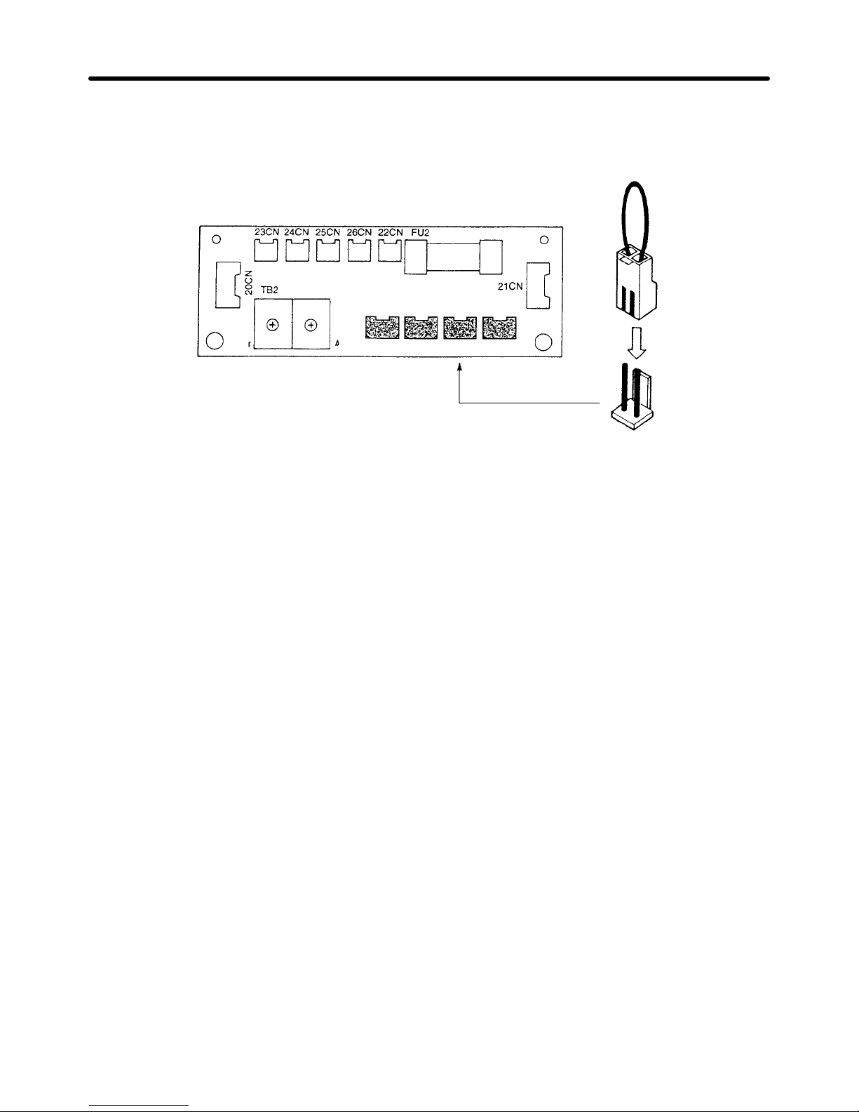
D Setting the Power Supply Voltage Short Pin (400-V Class Inverters of 18.5 kW or
More)
Set the power supply voltage short pin for 400-V Class Inverters with a capacity of 18.5 kW or more.
Short Pin Setting Procedure
1. Turn
OFF the power supply and wait for at least one minute (three minutes for
Inverters of 30 kW or
more) before removing the front panel.
Installation Chapter 2
Page 46
2-24
2. Insert the short pin mounted on the board into the voltage connector nearest to the actual power
supply voltage. The default setting is 440 V.
The following example shows board of a 400-V Class Inverter of 18.5 to 45 kW.
380 V 400/415 V 440 V 460 V
3. Put the front panel to its original position.
H Wiring on the Output Side of Main Circuit
D Connecting the Terminal Block to the Load
Connect output terminals T1 (U), T2 (V), and T3 (W) to motor lead wires T1 (U), T2 (V), and T3 (W),
respectively.
Check that the motor rotates forward with the
forward command. Switch over any two of
the output terminals to each other and reconnect if the motor rotates in reverse with the forward com
-
mand.
D Never Connect a Power Supply to Output Terminals
Never
connect a power supply to output terminals T1 (U), T2 (V), and T3 (W). If voltage is applied to the
output terminals, the internal circuit of the Inverter will be damaged.
D Never Short or Ground Output Terminals
If
the output terminals are touched with bare hands or the output wires come into contact with the Invert
-
er
casing, an electric shock or grounding will occur
. This is extremely hazardous. Also, be careful not to
short the output wires.
D Do Not Use a Phase Advancing Capacitor or Noise Filter
Never
to connect a phase advance capacitor or LC/RC noise filter to the output circuit. Doing so may
result in damage to the Inverter or cause other parts to burn.
D Do Not Use an Electromagnetic Switch or Magnetic Contactor
Do
not connect an electromagnetic switch or magnetic contactor to the output circuit. If a load is con
-
nected
to the Inverter during running, an inrush current will actuate the overcurrent protective circuit in
the Inverter.
Installation Chapter 2
Page 47

2-25
D Installing a Thermal Relay
This Inverter has an electronic thermal protection function to protect the motor from overheating. If,
however,
more than one motor is operated with one Inverter or multi-polar motor is used, always install a
thermal relay (THR) between the Inverter and the motor and set n033 to 0 (no thermal protection).
In
this case, program the sequence so that the magnetic contactor on the input side
of the main circuit is
turned off by the contact of the thermal relay.
D Installing a Noise Filter on Output Side
Connect a noise filter to the output side of the Inverter to reduce radio noise and induction noise.
Noise
filter
Power
supply
Signal line
Controller
Induction
noise
Radio noise
AM radio
3G3HV
Induction Noise: Electromagnetic
induction generates noise
on the signal line, causing the controller
to malfunction.
Radio Noise: Electromagnetic waves from the Inverter and cables cause the broadcasting radio
receiver to make noise.
D Countermeasures Against Induction Noise
As
described previously
, a noise filter
can be used to prevent induction noise from being generated on
the
output side. Alternatively
, cables can be routed through a grounded metal pipe to prevent induction
noise.
Keeping the metal pipe at least 30 cm away from the signal line considerably reduces induction
noise.
Controller
30 cm min.
Signal line
Power
supply
Metal pipe
3G3HV
Installation Chapter 2
Page 48

2-26
D Countermeasures Against Radio Interference
Radio
noise is generated from the Inverter as well as the input
and output lines. T
o reduce radio noise,
install
noise filters on both input and output sides, and also install the Inverter in a totally enclosed steel
box. The cable between the Inverter and the motor should be as short as possible.
Power
supply
Noise
filter
Noise
filter
Steel box
Metal pipe
3G3HV
D Cable Length between Inverter and Motor
As
the cable length between the Inverter and the motor
is increased, the floating capacity between the
Inverter
outputs and the ground is increased proportionally
. The increase in floating capacity at the In
verter outputs causes the high-frequency leakage current to increase, and this may adversely affect
peripheral
devices and the current detector in the Inverter’s output section. T
o prevent this from occur
ring,
use a cable of no more than 100 meters between the Inverter and the motor
. If the cable must
be
longer
than 100
meters, take measures to reduce the floating capacity by not wiring in metallic ducts, by
using a separate cable for each phase, and so on.
Also
adjust the carrier frequency according to the cable length between the Inverter and the motor
, as
shown in the table below.
Cable length 50 m max. 100 m max. More than 100 m
Carrier frequency (n050) 15 kHz max (6 max.) 10 kHz max. (4 max.) 5 kHz max. (2 max.)
Note The carrier frequency setting range varies depending on the Inverter capacity.
200-V class, 22 kW max.; 400-V class, 22 kW max.: 0.4 to 15.0 kHz
200-V class, 30 to 75 kW; 400-V class, 30 to 160 kW: 0.4 to 10.0 kHz
400-V class, 185 to 300 kW: 0.4 to 2.5 kHz
D Single-phase Motors Cannot Be Used
The Inverter is not suited for the variable speed control of single-phase motors.
Single-phase
motors are either capacitor start motors or split-phase start
motors. (The method for de
termining
rotation direction at startup is dif
ferent.) If a capacitor start motor is used, the capacitor may be
damaged
by a sudden electric discharge caused by Inverter output. If a split-phase start motor is used,
the starting coil may burn because the centrifugal switch does not operate.
Installation Chapter 2
Page 49

2-27
H Ground Wiring
• Always
use the ground terminal of the 200-V Inverter with a ground resistance of less than 100 Ω and
that of the 400-V Inverter with a ground resistance of less than 10 Ω.
• Do not share the ground wire with other devices such as welding machines or power tools.
• Always use a ground wire that complies with technical standards on electrical equipment and mini-
mize the length of the ground wire.
Leakage
current flows through the Inverter
. Therefore, if the distance between the ground electrode
and
the ground terminal is too long, potential on the ground terminal of the Inverter will become unsta
-
ble.
• When using more than one Inverter, be careful not to loop the ground wire.
Installation Chapter 2
Page 50

2-28
H Countermeasures against Harmonics
With
the continuing development of electronics, the generation of harmonics from industrial machines
has
been causing problems recently
. Refer to the following for the definition of harmonics (i.e., harmonic
currents with voltages) and countermeasures against the generation of harmonics from the Inverter.
D Harmonics (Harmonic Currents with Voltages)
• Definition
Harmonics
consist of electric power produced
from AC power and alternating at frequencies that are
integral multiples of the frequency of the AC power.
The following are the harmonic frequencies of a 60- or 50-Hz commercial power supply.
Second harmonic: 120 (100) Hz
Third harmonic: 180 (150) Hz
Basic frequency
(60 Hz)
Second harmonic (120 Hz)
Third harmonic (180 Hz)
• Problems Caused by the Harmonics Generation
The
waveform
of commercial power supply will be distorted if the commercial power supply contains
excessive harmonic currents.
Machines with such a commercial power supply will malfunction or generate excessive heat.
Third harmonic (180 Hz)Basic frequency (60 Hz)
Distorted current
waveform
D Causes of Harmonics Generation
• Usually,
electric machines have built-in circuitry that converts commercial AC power
supply into DC
power.
Such AC power
, however
, contains harmonics due to the dif
ference in current flow between AC
and DC.
• Obtaining DC from AC using Rectifiers and Capacitors
DC
voltage is obtained by converting AC voltage into a pulsating one-side voltage with rectifiers
and
smoothing the pulsating one-side voltage with capacitors. Such AC, however, contains harmonics.
Installation Chapter 2
Page 51

!
2-29
• Inverter
The
Inverter as well as normal electric machines has an output current containing harmonics because
the Inverter converts AC into DC.
The
output current of the Inverter
is comparatively high. Therefore, the ratio of harmonics in the output
current of the Inverter is higher than that of any other electric machine.
Voltage
Voltage
Voltage
Current
Time
Time
Time
Time
Rectified
Smoothed
A current flows into the capacitors. The
current is different from the voltage in
waveform.
D Countermeasures with Reactors against Harmonics Generation
• DC/AC Reactors
The
DC reactor and AC reactor suppress harmonics and currents that change suddenly and greatly
.
The
DC reactor suppresses harmonics better than the AC reactor
. The DC reactor used with the AC
reactor suppresses harmonics more effectively.
The
input power factor of the Inverter is improved by suppressing the harmonics in the input current of
the Inverter.
Note 18.5- to 160-kW Inverters have a built-in DC reactor.
185- to 300-kW Inverters cannot use a DC reactor.
• Connection
Connect the DC reactor to the internal DC power supply of the Inverter after shutting off the power
supply to the Inverter and making sure that the charge indicator of the Inverter turns off.
WARNING Do
not touch the internal circuitry of the Inverter in operation, otherwise an electric
shock or a burn injury may occur.
Installation Chapter 2
Page 52

2-30
• Wiring Method
With DC Reactor
3G3HV
200 VAC (400 V)
DC reactor
(optional)
L1 (R)
L2 (S)
L3 (T)
T1 (U)
T2 (V)
T3 (W)
Note Be sure to remove the short bar on terminals +1 and +2 before connecting the DC reactor.
With DC and AC Reactors
3G3HV
200 VAC (400 V)
DC reactor
(optional)
AC reactor
(optional)
L1 (R)
L2 (S)
L3 (T)
T1 (U)
T2 (V)
T3 (W)
Note Be sure to remove the short bar on terminals +1 and +2 before connecting the DC reactor.
• Reactor Effects
Harmonics
are ef
fectively suppressed when the DC reactor is used with the AC reactor as shown in
the following table.
Harmonic suppres-
Harmonic generation rate (%)
pp
sion method
5th har-
monic
7th har-
monic
11th
harmon-
ic
13th
harmon-
ic
17th
harmon-
ic
19th
harmon-
ic
23th
harmon-
ic
25th
har-
monic
No reactor 65 41 8.5 7.7 4.3 3.1 2.6 1.8
AC reactor 38 14.5 7.4 3.4 3.2 1.9 1.7 1.3
DC reactor 30 13 8.4 5 4.7 3.2 3.0 2.2
DC and AC reactors 28 9.1 7.2 4.1 3.2 2.4 1.6 1.4
Installation Chapter 2
Page 53

2-31
D Countermeasures with 12-pulse Rectification against Harmonics Generation
• 12-pulse Rectification
The
3G3HV
-series Inverter
with an output of 18.5 to 160 kW can employ 12-pulse rectification, which
suppresses harmonics better than reactors. The 3G3HV-series Inverter with an output of 15 kW or
less and 185 kW or more cannot employ 12-pulse rectification.
• Wiring Method
1. Terminals
L1 (R) and L1
1 (R1), L2 (S) and L21 (S1), and L3 (T) and L31 (T1) are short-circuited with
short
bars before shipping.
Be sure to remove the short bars when employing 12-pulse rectification,
otherwise the Inverter will break down.
2. Do not ground the secondary winding side of the transformer, otherwise the Inverter may break
down.
With Input Transformer for 12-pulse Rectification
200 VAC (400 V)
Input transformer for
12-pulse rectification
3G3HV
L1 (R)
L2 (S)
L3 (T)
T1 (U)
T2 (V)
T3 (W)
L11 (R1)
L21 (S1)
L31 (T1)
With Standard Transformers for 12-pulse Rectification
200 VAC (400 V)
Star-star insulating
transformer
3G3HV
Star-delta insulating
transformer
L1 (R)
L2 (S)
L3 (T)
T1 (U)
T2 (V)
T3 (W)
L11 (R1)
L21 (S1)
L31 (T1)
Note Use insulating transformers.
Installation Chapter 2
Page 54

2-32
• Input Transformers for 12-pulse Rectification
Refer
to the following table to select the input transformer for 12-pulse rectification. Refer to the mini
-
mum
currents on the secondary winding side in the table
when selecting two standard transformers
used in combination for 12-pulse rectification.
Inverter model
3G3HV-
Input voltage (V) Minimum current on
the primary winding
side (A)
Minimum current on
the secondary winding
side (A)
B2185
I/O voltage ratio: 1:1
100 50
B2220
g
200 to 230 V ±10%/
120 60
B2300
200 to 230 V ±10% at
164 82
B2370
50/60 Hz
200 100
B2450 230 115
B2550 280 140
B2750
380 190
B4185
I/O voltage ratio: 1:1
52 26
B4220
g
380 to 460 V ±10%/
66 33
B4300
380 to 460 V±10% at
82 41
B4370
50/60 Hz
100 50
B4450 120 60
B4550 180 80
B4750 206 103
B411K 280 140
B416K 380 190
• 12-pulse Rectification Effect
Harmonics are suppressed effectively with 12-pulse rectification as shown in the following table.
Harmonic suppres-
Harmonic generation rate (%)
pp
sion method
5th har-
monic
7th har-
monic
11th
harmon-
ic
13th
harmon-
ic
17th
harmon-
ic
19th
harmon-
ic
23th
harmon-
ic
25th
har-
monic
No reactor 65 41 8.5 7.7 4.3 3.1 2.6 1.8
12-pulse rectification 5.43 5.28 5.40 5.96 0.69 0.19 1.49 1.18
H Braking Resistor Unit and Braking Unit
• Connect the Braking Resistor Unit and Braking Unit to the Inverter as shown in the following.
• Set
n079 to 0 (i.e., no overheating protection of the Braking Resistor Unit) and n070 to 0 (i.e., no decel
-
erating stall prevention) before using the Inverter with the Braking Resistor Unit connected.
Note 1. Set n079 to 0 before operating the Inverter with the Braking Resistor Unit without thermal
relay trip contacts.
Note 2. The
Braking Resistor Unit cannot be used and the deceleration time cannot be shortened by
the Inverter if n070 is set to 1 (i.e., decelerating stall prevention).
• To
prevent the Unit from overheating, make a power supply sequence as shown below or connect the
thermal relay trip output of the Unit to the remote error input terminal of the Inverter to interrupt the
operation of the Inverter.
• The Braking Resistor Unit or Braking Unit cannot be connected to the Inverter with an output of
18.5 kW to 160 kW.
Installation Chapter 2
Page 55

2-33
D 200-V Class with 3.7- to 7.5-kW Output and 400-V Class with 3.7- to 15-kW Output
Inverter
Braking Resistor Unit
Thermal relay
trip contact
D 200-V Class with 11- to 15-kW Output and 400-V Class with 185- to 300-kW Output
Inverter
Thermal relay
trip contact
Control Unit
Braking Resistor Unit
Thermal relay trip contact
D Connecting Braking Units in Parallel
When connecting two or more Braking Units in parallel, use the wiring and connectors shown in the
following diagram.
There are connectors for selecting whether each Braking Unit is to be a Master or
Slave.
Select “Master” for the first Braking Unit only; select “Slave” for all other Braking Units (i.e., from
the second Unit onwards).
Inverter
Thermal
relay trip
contact
Braking
Resistor
Unit
Braking Unit #1
Braking Unit #2
Braking Unit #3
Thermal
relay trip
contact
Thermal
relay trip
contact
Braking
Resistor
Unit
Thermal
relay trip
contact
Braking
Resistor
Unit
Thermal
relay trip
contact
Thermal
relay trip
contact
Installation Chapter 2
Page 56

2-34
D Power Supply Sequence
200-V class:
Three-phase, 200 to
230 V
AC (50/60 Hz)
400-V class:
Three-phase, 380 to
460 V
AC (50/60 Hz)
Power
supply
Inverter
(See note)
Note Use a transformer with 200- and 400-V outputs for the power supply of the 400-V Inverter.
2-2-5 Wiring Control Circuit Terminals
A
control signal line must be 50 m maximum and separated from power lines. The fre
-
quency reference must be input to the Inverter through twisted-pair wires.
H Wire Size and Solderless Terminals
Use thick wires to prevent voltage drops if the wires are long.
D Wires for All Inverter Models
Terminal Terminal
screw
Wire thickness (mm2) Type
S1, S2, S3, S4, S5, S6, SC,
FV, FI, FS, FC, AM, AC, M1,
M2, MA, MB, MC
--- Stranded wire: 0.5 to 1.25
Single wire: 0.5 to 1.25
Shielded, twisted-pair wire
Shielded,
polyethylene-covered, vinyl
E (G) M3.5 0.5 to 2
yy ,y
sheath cable
D Solderless Terminals for Control Circuit Terminals
The use of solderless terminals for the control circuit terminals is recommended because solderless
terminals are easy to connect securely.
Wire thickness Model d1 d2 Manufacturer
0.5 mm
2
A1 0.5-8WH 1.00 2.60
Phoenix Contact
0.75 mm
2
A1 0.75-8GY 1.20 2.80
1 mm
2
A1 1-8RD 1.40 3.00
1.5 mm
2
A1 1.5-8BK 1.70 3.50
Installation Chapter 2
d1
dia.
d2 dia.
Page 57

2-35
Note Do
not solder wires with the control circuit terminals if wires are used instead of solderless termi
nals. Wires may not contact well with the control circuit terminals or the wires may be disconnected from the control circuit terminals due to vibration if the wires are soldered.
D Round Solderless Terminals for Ground Terminal
Wire thickness
(mm2)
Terminal
screw
Size
0.5
M3.5
1.25 to 3.5
0.75 1.25 to 3.5
1.25 1.25 to 3.5
2 2 to 3.5
H Wiring Control Circuit Terminals
D Wiring Method
1. Loosen the terminal screws with a thin-slotted screwdriver.
2. Insert the wires from underneath the terminal block.
3. Tighten the terminal screws firmly.
Note 1. Always
separate the control signal line from the main circuit cables and other power cables.
Note 2. Do
not solder the wires to the control circuit terminals. The wires may not contact well with the
control circuit terminals if the wires are soldered.
Note 3. The
end of each wire connected to the control circuit terminals must be
stripped for approxi
-
mately 7 mm.
Note 4. Use a shielded wire for the ground terminal.
Note 5. Insulate the shield with tape so that the shield will not touch any signal line or device.
Strip
the end for 7 mm if
no solderless terminal is
used.
Wires
Thin-slotted screwdriver
Control circuit
terminal block
Solderless terminal or
wire without soldering
Blade of screwdriver
3.5 mm max.
Blade thickness: 0.6 mm max.
Note Tighten
screws to a torque between 0.5 and 0.6 NSm. T
ightening to a torque greater than this may
cause
the terminal block to be damaged. Tightening to a torque less than this may result in mal
-
function or short-circuiting.
Installation Chapter 2
Page 58

Chapter 3
Preparing for Operation
3-1 Preparation Procedure
3-2 Using the Digital Operator
3-3 Test Run
3-4 Basic Operation
3-5 Applied Operation
3
Page 59

!
!
!
!
!
!
!
!
!
!
!
!
3-2
H Cautions and Warnings
WARNING Turn
ON the input power supply only after mounting the front cover
, terminal covers,
bottom cover, Operator, and optional items. Not doing so may result in electrical
shock.
WARNING Do
not remove the front cover
, terminal covers, bottom cover
, Operator
, or optional
items
while the power is being supplied. Not doing so may result in electrical shock or
damage to the product.
WARNING Do not operate the Operator or switches with wet hands. Doing so may result in
electrical shock.
WARNING Do not touch the inside of the Inverter. Doing so may result in electrical shock.
WARNING Do
not
come close to the machine when using the error retry function because the
machine
may abruptly start when stopped by an alarm. Doing so may result in injury
.
WARNING Do not come close to the machine immediately after resetting momentary power
interruption
to avoid an unexpected restart (if operation is set to be continued in the
processing
selection function after momentary power
interruption is reset). Doing so
may result in injury.
WARNING Provide
a separate emergency stop switch because the ST
OP Key on the Operator
is valid only when function
settings
are performed. Not doing so may result in injury
.
WARNING Be sure confirm that the RUN signal is turned OFF before turning ON the power
supply, resetting the alarm, or switching the LOCAL/REMOTE selector. Doing so
while the RUN signal is turned ON may result in injury.
Caution Be sure to confirm permissible ranges of motors and machines before operation
because the Inverter speed can be easily changed from low to high. Not doing so
may result in damage to the product.
Caution Provide
a separate holding brake when necessary
. Not doing so may result in injury
.
Caution Do
not perform
a signal check during operation. Doing so may result in injury or dam
-
age to the product.
Caution Do not carelessly change settings. Doing so may result in injury or damage to the
product.
Preparing for Operation Chapter 3
Page 60

3-3
3-1 Preparation Procedure
1. Installation
Install the Inverter according to installation conditions. Refer to
page 2-7
.
S Check that all the installation conditions are met.
2. Wiring
Connect the power supply and peripheral devices. Refer to
page 2-10
.
S Select peripheral devices that meet the specifications, and wire them correctly.
3. Turning the Power ON
Check the necessary items, then turn the power ON.
S Check
that the power voltage is correct and the power input terminals (L1 (R), L2 (S), and L3 (T))
are wired correctly. Supply three-phase, 200 to 230 VAC (50/60 Hz) to the 200-V Inverter and
three-phase 380 to 460 VAC (50/60 Hz) to the 400-V Inverter.
S Check
that the motor output terminals (T1 (U), T2
(V), and T3 (W)) and motor are connected cor
-
rectly.
S Check that the control circuit terminals and controller are connected correctly.
4. Checking the Display Status
Check the Inverter for errors.
S If
everything is normal, the data display will show the
data selected with a monitor item indicator
.
S
If the Inverter is error
, the data display will show data indicating that the Inverter is error
. Refer to
Section 4 Operation
for details.
5. Setting the Parameters
Use the Digital Operator to set parameters required for operation. Refer to
page 3-4
.
S Set each parameter as described in this manual.
6. Test RUN
Use the Digital Operator to rotate the motor. Refer to
page 3-10
.
S Check that the motor is rotating normally.
7. Operation
Basic operation (The Inverter operates with basic settings). Refer to
page 3-13
.
Applied
operation (The Inverter performs energy-saving control, PID
control, or other applied con
-
trol). Refer to
page 3-25
.
S Refer to
3-4 Basic Operation
for operation with basic parameters only.
S Refer to
3-4 Basic Operation
and
3-5 Applied Operation
for energy-saving control, PID control,
frequency jumping, error retrying, or S-shaped acceleration and deceleration.
S Refer to
3-5 Applied Operation
for parameters in detail.
Preparing for Operation Chapter 3
Page 61

3-4
3-2 Using the Digital Operator
3-2-1 Nomenclature
Easy-setting
indicators
Displays basic parameter
constants and monitor items.
(See note 1.)
Mode Key
Switches basic parameter
constant and monitor items.
Operation Mode Selection Key
Switches between operation by the
Digital Operator and operation
specified in the operation mode
selection parameter (n002).
Run Key
Starts the Inverter
.
Operation Mode Indicators
External Operation:
Lit when operating references from exter
-
nal terminals are in ef
fect.
Analog Input:
Lit when high-frequency references from
external analog terminals are in ef
fect.
Data Display
Displays frequency reference, out
-
put frequency
, output current,
constant set values, Inverter status,
etc.
Enter Key
Enters set value when pressed after
constant has been set.
Increment Key
Increments numbers when pressed
during setting of constant number
and constant data.
Decrement Key
Decrements numbers when
pressed during setting of constant
number and constant data.
Stop/Reset Key
Stops the Inverter
. Also resets after
alarm has been generated. (See note 2.)
DIGITAL OPERATOR PJVOP131E
Fref Fout Iout kWout
F/R Montr Accel Decel
Vmtr V/F Fgain Fbias
FLA PID kWsav PRGM
LOCAL
REMOTE
RUN
STOP
RESET
REMOTE
SEQ REF
Note 1. The
Inverter does not start while any indicator
on the bottom two lines is lit. T
o start the Invert
-
er,
press the Mode Key to light up an indicator on
the top two lines and press the RUN Key
.
Note 2. For safety reasons, the reset function cannot be used while the run command (forward/re-
verse) is being input. Turn the run command OFF before using the reset function.
Preparing for Operation Chapter 3
Page 62
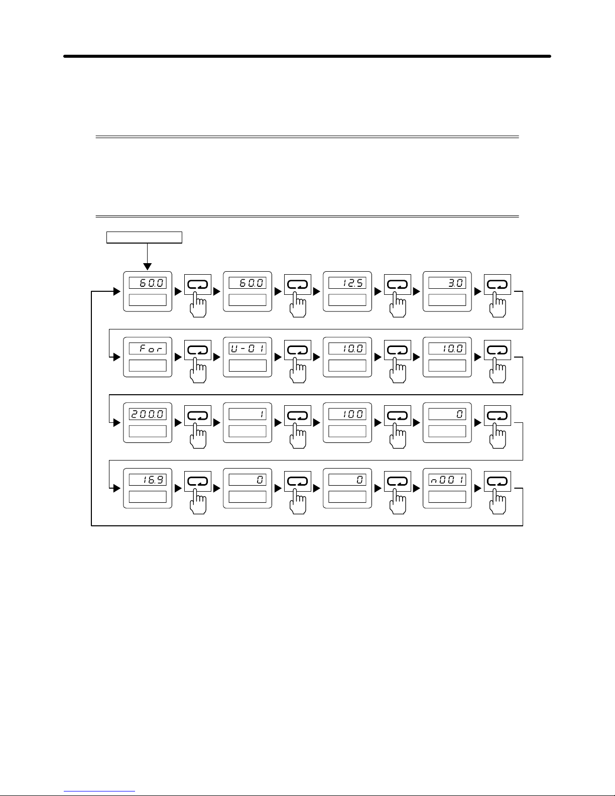
3-5
3-2-2 Summary
H Data Display
Press the Mode Key to select the item displayed on the data display.
The items on the first two lines of the monitor item indicators can be set or monitored
while the Inverter is running.
All
the items of the monitor item indicators can be set or monitored while the Inverter is
not running.
Speed
setting/Monitor
Output frequency
monitor
Output current monitor
Output power monitor
Operator forward/
reverse selection
Monitor selection
Acceleration time
setting
Deceleration time
setting
Motor rated
voltage setting
V/f pattern selection
Frequency reference
gain
Frequency reference
bias
Motor rated
current setting
PID control selection
Energy-saving control
selection
Constant setting mode
Power supply ON
Fref Fout Iout kWout
F/R Montr Accel Decel
Vmtr V/F Fgain Fbias
FLA PID kWsav PRGM
Note The following items can be set or monitored with the monitor item indicators.
Preparing for Operation Chapter 3
Page 63

3-6
Indicator Item Function
Fref Speed setting/Monitor The frequency reference can be set or monitored. The unit to
be used can be set with n024.
Fout Output frequency
monitor
The output frequency can be monitored. The setting unit can
be set with n024.
Iout Output current
monitor
The output current can be monitored in 0.1-A units.
kWout Output power monitor The output power can be monitored in 0.1-kW units.
F/R Operator
forward/reverse
selection
The forward or reverse rotation of the motor can be set or
checked. This item can be set with the Digital Operator only.
Montr Monitor selection Thirteen items can be monitored.
Accel Acceleration time
setting
Acceleration time 1 can be set or checked with n019 in 1-s
units if acceleration time 1 is set to 1,000 or a larger value and
0.1-s units if acceleration time 1 is set to a value less than
1,000.
Decel Deceleration time
setting
Deceleration time 1 can be set or checked with n020 in 1-s
units if the deceleration time is set to 1,000 or a larger value
and 0.1-s units if the deceleration time is set to a value less
than 1,000.
Vmtr Motor rated voltage
setting
The rated input voltage of the motor can be set with n011 while
the Inverter is not running.
V/F V/f pattern selection The V/f pattern can be set with n010 while the Inverter is not
running.
Fgain Frequency reference
gain
The frequency reference gain can be set with n046 while the
Inverter is not running.
Fbias Frequency reference
bias
The frequency reference bias can be set with n047 while the
Inverter is not running.
FLA Motor rated current
setting
The rated input current of the motor can be set with n032 while
the Inverter is not running.
PID PID control selection The PID control function can be selected with n084 while the
Inverter is not running.
kWsav Energy-saving control
selection
The energy-saving control function can be selected with n095
while the Inverter is not running.
PRGM Constant setting
mode
All parameters can be set or checked.
Preparing for Operation Chapter 3
Page 64

3-7
H Parameters
Parameters can be set with the monitor item indicators or by designating the corresponding
parameter numbers. Basic parameters can be set with the monitor item indica
tors. Parameter settings with the monitor item indicators are different in method from
parameter settings by designating the corresponding parameter constants.
D Setting Parameter Constants with the Indicators
Example: Changing Acceleration Time From 10 s to 50 s
Acceleration
time:
10 s
Change
data
Data flashes
during change
Enter
data
Acceleration
time: 50 s
T
o another
setting
Accel Accel Accel
D Setting Parameter Constants by Specifying Parameter Constant Number
Example: Setting Constant No. 025 (Frequency Reference 1)
Display
constant
Change
constant
number
Display
constant no. 25
Return to constant
number display
T
o another
constant
setting
Display contents of
constant no. 25
Change
data
Data flashes
during change
Enter
data
Displayed for
approx. 1 s
PRGM PRGM PRGM
PRGM PRGM PRGM PRGM
Note There are some parameters that cannot be changed while the Inverter is running. To change
these parameter, stop the Inverter first.
H Checking Monitor Contents
Example: Checking Output Voltage (Monitor Item No. U-04)
Display
monitor
Change
monitor
item
Display
U-04
Check
monitor
contents
Monitor
output
voltage
T
o another
monitor
Montr Montr Montr
Preparing for Operation Chapter 3
Page 65

3-8
D Monitor Display Table
Monitor No. Monitor item Description
U-01 Frequency
reference
The frequency reference can be monitored. The display unit can be set
with n024. The frequency reference can be monitored with the FREF
indicator as well.
U-02 Output frequency The output frequency can be monitored. The display unit can be set
with n024. The output frequency can be monitored with the
FREQUENCY indicator as well.
U-03 Output current The output current can be monitored in 0.1-A units. The output current
can be monitored with 0.1-A units with the IOUT indicator as well.
U-04 Output voltage The output voltage can be monitored in 1-V units.
U-05 DC voltage The DC voltage can be monitored in 1-V units.
U-06 Output power The output power can be monitored in 0.1-kW units. The output power
can be monitored in 0.1-kW units with the POWER indicator as well.
U-07 Input terminal
status
The statuses of input terminals S1 to S6 can be monitored.
Lit when S1 is ON.
Lit when S2 is ON.
Lit when S3 is ON.
Lit when S4 is ON.
Lit when S5 is ON.
Lit when S6 is ON.
Not used (Not lit).
U-08 Inverter status The status of the Inverter can be monitored.
Lit while the Inverter is running.
Lit when the reverse rotation command is given.
Lit when the Inverter is ready to operate.
Lit when the Inverter is error.
Not used (Not lit).
Lit when MA, MB, and MC outputs are ON.
Lit when outputs M1 and M2 are ON.
U-09 Error before
power interruption
The four most-recent errors before the power supplied to the Inverter is
turned OFF can be checked.
U-10 PROM number For the manufacturer’s use.
U-11 Total operating
time (rightmost 4
digits)
The accumulated operating time can be monitored with 1-h units. The
maximum value is 279,620 h.
Accumulated operating time (h) = U-12 value x 10,000 + U-11 value
U-12 Total operating
time (leftmost 2
digits)
g() ,
U-13 PID feedback
value
The PID feedback can be monitored in 0.1-Hz units.
H Operation Mode Selection Key/Operation Mode Selection Input
The operation mode of the Inverter can be changed using the Operation Mode Selection Key on the
Digital
Operator
. Using this key
, it is possible to switch between the two operation modes shown below
.
Preparing for Operation Chapter 3
Page 66

3-9
The same kind of switching is also possible with control circuit terminals set using the multi-function
input parameters 1 to 5 (set value: 5).
Operation mode Description Contents
Remote Inverter operates according to control
signals from a higher level control
system.
Run commands and frequency
references determined by the setting of
the operation mode selection parameter
(n002).
Local Inverter operates alone in order to check
operation directly related to the Inverter.
Run commands: RUN and STOP/RESET
Keys.
Frequency reference: Value set with the
Digital Operator.
Note Performs operation for a operation
mode selection parameter value
(n002) of 0.
Note 1. The
operation mode will always be
Remote mode when power is supplied. Therefore, to start
operation
immediately after power is supplied, set n002 to the required settings in advance.
Note 2. If n002 is set to 0, there is no difference in the two modes.
Note 3. Frequencies
set from the Digital Operator using the speed setting
will be entered in frequency
reference parameters 1 to 4 (n025 to n028) or the inching frequency reference parameter
(n029) regardless of whether the mode is Remote mode or Local mode.
Note 4. Multi-function
inputs 1 to 5 will be enabled regardless of whether the mode is Remote mode
or
Local mode. The following settings, however, will be disabled in Local mode.
S Reverse rotation/stop (2-wire sequence selection); Set value: 0
S Stop command (3-wire sequence selection); Set value: 1
Note 5. For
safety reasons, run signals input while changing
from Local mode to Remote mode are
usually ignored. Input the run signal again after the mode has changed. It is possible, however,
to stop such run signals being ignored
by setting the Operation Selection at Operation
Mode
switching (Local/Remote switching) parameter (n1
14) to 1. If this setting is made, when
the
mode
changes from Local mode to Remote mode, the Inverter will start running immedi
-
ately. Take steps to ensure the safety of the system for such operation.
Preparing for Operation Chapter 3
Page 67

3-10
3-3 Test Run
After
wiring is complete, perform a test run of the Inverter
. First, start the motor through
the
Digital Operator without connecting the motor to the mechanical system. Next, con
-
nect
the motor to the mechanical system and perform a test run. Finally
, operate the con
-
troller
to make sure that the sequence of operations
is correct. Refer to the following to
perform a test run of the Inverter.
1. Wiring
S Check that power is connected to power input terminals L1 (R), L2 (S), and L3 (T).
Supply
three-phase, 200 to 230 V
AC (50/60 Hz) to the
200-V Inverter and three-phase 380 to 460
VAC (50/50 Hz) to the 400-V Inverter.
S Check
that terminals T1 (U), T2 (V), and T3 (W) are correctly connected to the motor power cables.
S Do not load the motor with a mechanical system. Check that the motor has no load.
S Check
that the forward/stop and reverse/stop inputs are OFF before connecting signal lines to the
control circuit terminals.
2. Turning Power ON and Checking Indicator Display
S Supply power to the Inverter.
S Check that the data display is not showing any error.
3. Parameter Initialization
S Set n001 to 6 to initialize all parameters.
Key Indicator Data example Explanation
Mode Key PRGM n001 Press the Mode Key until the PRGM indicator is lit.
Enter Key PRGM 1 Check that “n001” is displayed and press the Enter
Key so that the data of n001 will be displayed.
If “n001” is not displayed, press the Increment Key or
Decrement Key so that “n001” will be displayed.
Then press the Enter Key.
Up/Down Key PRGM 6
(Flashing)
Press the Increment Key or Decrement Key so that
“6” will be displayed, in which case the data display
will flash.
Enter Key PRGM end Press the Enter Key.
“End” will appear for approximately 1 s.
PRGM 1 After “End” appears, n001 will be initialized and “1”
will be displayed.
Mode Key PRGM n001 Press the Mode Key so that “n001” will be displayed.
4. Rated Input Voltage of Motor
S Set the rated input voltage of the motor with the Digital Operator.
S The
200-V Inverter is set to 200.0 V and the 400-V Inverter is set to 400.0 V as rated input voltages
of motors before shipping.
Preparing for Operation Chapter 3
Page 68

3-11
S Check the rated input voltage of the motor and set the rated input voltage of the motor.
Example: Motor with Rated Input Voltage of 180 V
Key Indicator Data example Explanation
Mode Key Vmtr 200.0 Press the Mode Key until the MOTOR VOLTAGE
indicator is lit.
Down Key Vmtr 180.0
(Flashing)
Press the Increment Key so that “180.0” will be
displayed, in which case the data display will flash.
Enter Key Vmtr 180.0 Press the Enter Key.
5. Rated Input Current of Motor
S Set the rated input current of the motor with the Digital Operator.
S The default-set value varies with the Inverter model.
S Check the rated input current of the motor and set the rated input current.
Example: Motor with Rated Input Current of 8.5 A
Key Indicator Data example Explanation
Mode Key FLA 14.1 Press the Mode Key until the MOTOR CURRENT
indicator is lit.
Down Key FLA 8.5
(Flashing)
Press the Increment Key so that “8.5” will be
displayed, in which case the data display will flash.
Enter Key FLA 8.5 Press the Enter Key.
6. Frequency Reference
S Set the frequency according to the rotation speed of the motor.
S Press
the Mode Key until the FREF indicator is lit, press the Increment Key or Decrement Key
to
set the frequency, and press the Enter Key.
7. Operation With No Load
S Press the Operation Mode Selection Key.
S Check
that the operation mode indicators (i.e., the remote RUN indicator and analog input indica
-
tor) are not lit.
S Press the RUN Key to start the motor.
S To
change the rotation direction of the motor
, press the Mode Key until the F/R indicator is lit, press
the Increment Key or Decrement Key to set the rotation direction, and press the Enter Key.
Indicator Data example Explanation
F/R
f%r Forward rotation command
reU Reverse rotation command
S Check that the motor is rotating without error vibration or noise after the frequency reference or
rotation direction is changed.
S To stop the motor, press the STOP/RESET Key.
8. Mechanical System
S Load the motor with the mechanical system after making sure that the motor rotates normally.
S Before
loading
the motor with the mechanical system, check that the output of the Inverter is inter
-
rupted and the motor stops by pressing the STOP/RESET Key.
9. V/f Pattern
S Set the V/f pattern according to the characteristics of the mechanical system.
Preparing for Operation Chapter 3
Page 69

3-12
S Press the Mode Key until the V/F indicator is lit.
S The following two methods are available to set the V/f pattern.
S Select
one of the fixed 15
V/f patterns preset with the Inverter
, in which case set the V/f pattern
to 0, 1, 2, 3, 4, 5, 6, 7, 8, 9, A, b, C, d, or E.
S Set the V/f pattern to F for an optional V/f pattern.
S The
following are the fixed V/f patterns preset
with the Inverter
. Refer to
3-4 Basic Operation
for
details.
Characteristic Use Set
value
Specification
General These V/f patterns are mainly used for
0 50 Hz
purpose
y
general purposes, such as the control
pp
1 60 Hz
of straight conveyor lines.Applythese
V/f patterns to the motor if the rotation
speed of the motor must change in
2 60 Hz. Voltage saturation at
50 Hz.
s eed of the motor must change in
almost direct proportion to the load
factor of the motor.
3 72 Hz. Voltage saturation at
60 Hz.
Reduced
These V/f patterns are mainly used for
p
p
pp
p
4 50 Hz with cube reduction.
torque fan pumps. Apply these V/f patterns to
the motor if the rotation speed of the
5 50 Hz with square reduction.
the motor if the rotation s eed of the
motor must change in square or cube
p
p
6 60 Hz with cube reduction.
proportiontotheloadfactor o
fth
e
motor.
7 60 Hz with square reduction.
High starting These V/f patterns are usually
8 50 Hz with low starting torque.
gg
torque
y
unnecessary because the Inverter has
9 50 Hz with high starting torque.
afull automatic torque boost function to
pp
p
A 60 Hz with low starting torque.
su ly enough ower to meet the
starting torque of the motor.
B 60 Hz with high starting torque.
Constant power
operation
These V/f patterns are used to rotate
the motor with an output at 60 Hz or
C 90 Hz. Voltage saturation at
60 Hz.
o e at o
t e oto t a out ut at 60 o
more. Apply these V/f patterns to the
motor to impose a constant voltage at
D 120 Hz. Voltage saturation at
60 Hz.
60 Hz min. on the motor.
E 180 Hz. Voltage saturation at
60 Hz.
S Select a V/f pattern suited to the mechanical system from the above V/f patterns.
S Set
the V/f pattern to F for an optional V/f pattern to be determined with n012 to n018. The optional
V/f pattern set with the Inverter before shipping is the same as the V/f pattern obtained with the set
value 1.
10. Operation with Actual Load
S Be ready to press the STOP/RESET Key for any error operation of the Inverter or the load.
S Use
the Digital
Operator to operate the Inverter in the same way as the operation of the Inverter
with no load.
S Set
the frequency reference so that
the motor will rotate at an approximately 10% of the rotation
speed of the motor in actual operation.
S Set
the frequency reference according to the actual rotation speed of the motor after making sure
that the mechanical system operates correctly and smoothly.
S Change the frequency reference and the rotation direction of the motor and check that the me-
chanical system operates without error vibration or noise.
Preparing for Operation Chapter 3
Page 70

3-13
3-4 Basic Operation
Refer
to the following for the basic settings required to start and stop operating the In
verter. Only these settings are required for the Inverter in basic operation. These settings
as well as other settings are required by the Inverter for any applied operation, such
as energy-saving control or PID control.
H Parameter Write Prohibit Selection (n001)
S The parameters used by the Inverter are classified into the following three groups.
Group 1: n001 to n034
Group 2: n035 to n049
Group 3: n050 to n108 (Up to n102 can be used.)
S The
Inverter is default-set so that only parameters of group 1 can be set and checked and the pa
-
rameters of groups 2 and 3 can only be checked.
S The
Inverter in basic operation uses the parameters
of groups 1 and 2. Therefore, set n001 to 2 or
3 so that these parameters can be checked and set.
n001 Parameter Write Prohibit Selection/Parameter Initialization
Setting range 0, 1, 2, 3, 6, and7Unit --- Default setting 1
Set Values
Set value Description
0 The parameters n001 can be set and checked and the parameters n002 to n108 can be only
checked.
1 The parameters of group 1 (i.e., n001 to n034) can be set and checked and the parameters of
groups 2 and 3 (i.e., n035 to n049 and n050 to n108) can be only checked.
2 The parameters of groups 1 and 2 can be set and checked and the parameters of group 3 can
only be checked.
3 The parameters of groups 1, 2, and 3 can be set and checked.
6 All parameters will be set to default-set values.
7 All parameters will be initialized with a three-wire sequence.
Note Do not set n001 to any value other than the above.
H Operation Mode Selection (n002)
S The Inverter has four operation modes. Select one of the modes with n002.
n002 Operation Mode Selection
Setting range 0 to 3 Unit --- Default setting 3
Set Values
Set value Run command Frequency reference
0 Digital Operator (RUN/STOP Key) Digital Operator (Frequency reference 1)
1 Control circuit terminals
(Forward/reverse/stop input)
Digital Operator (Frequency reference 1)
2 Digital Operator (RUN/STOP Key) Control circuit terminals (Analog input)
3 Control circuit terminals
(Forward/reverse/stop input)
Control circuit terminals (Analog input)
Preparing for Operation Chapter 3
Page 71

3-14
Note 1. Do not set n002 to any value other than the above.
Note 2. The
frequency reference input according to the operation mode selection setting
will be used
as frequency reference 1 in multi-step speed operation. If the frequency reference is determined
by control circuit terminals, the frequency reference input using the control circuit ter
-
minals’
analog input will be enabled and the frequency
reference 1 parameter setting (n025)
will
be ignored. (If, however
, the mode is changed to Local mode using the Digital Operator
,
then the value set in n025 will be enabled.)
Note 3. Frequency
references 2 to 4 (n026
to n028) and the inching frequency reference (n029) used
in
multi-step speed operation will be determined by the parameter settings, regardless of the
operation mode selection setting.
H Frequency Reference Type Selection (n042, n046, and n047) through
Control Circuit Terminal
S Select
the FV terminal to input the frequency reference within a voltage range from 0 to 10 VDC or
the
FI terminal to
input the frequency reference within a current range from 4 to 20 mA with n042.
n042 Analog Frequency Reference Voltage/Current Selection
Setting range 0, 1 Unit --- Default setting 0
Set Values
Set value Description
0 The FV terminal can be used for the analog frequency reference within a voltage range from 0
to 10 VDC.
1 The FI terminal can be used for the analog frequency reference. Set the input level with n043.
Note 1. The
FI terminal is a current input terminal for 4 to 20 mA. The FI terminal can be a voltage input
terminal
by changing
the FI input level with n043 and cutting jumper wire of the PCB. Do not,
however,
change the FI terminal to a voltage input terminal unless the Inverter is used for PID
control.
Note 2. Set n042 according to the type of frequency reference.
S Set the frequency reference gain with n046 and the frequency reference bias with n047.
n046 Frequency Reference Gain
Setting range 0 to 200 Unit % Default setting 100
n047 Frequency Reference Bias
Setting range –100 to 100 Unit % Default setting 0
Set Values
S n046: The
frequency for 10-V or 20-mA input can be
set in 1% units based on the maximum fre
-
quency set with n012 as 100%.
Preparing for Operation Chapter 3
Page 72

3-15
S n047: The frequency for 0-V or 4-mA input can be set in 1% units based on the maximum fre-
quency set with n012 as 100%.
Maximum frequency x
frequency reference
gain/100
Maximum frequency x
frequency reference
bias/100
Items in parentheses apply
when the frequency reference
is input with current.
Frequency
reference
0 V
(4 mA)
10 V
(20 mA)
Note The frequency reference gain and frequency reference bias can be set with
the GAIN indicator
and BIAS indicator.
H Frequency Reference Selection (n024 to n029) through Digital
Operator
S Frequency
references can be input through the Digital Operator by setting the unit of the
frequency
references
with n024 and the values of the frequency references with
n025 to n028. The inching
frequency reference must be set with n029 if an inching frequency is required.
n024 Unit of Frequency Reference
Setting range 0 to 3,999 Unit --- Default setting 0
Set Values
Set value Description
0 0.1-Hz units
1 0.1% units based on the maximum frequency as 100%.
2 to 39 r/min (r/min = 120 x frequency/n024
Set n024 to the number of poles of the motor.
40 to
3,999
Determine the display method of the maximum frequency set with n012. A frequency less
than the maximum frequency will be displayed proportionally.
Example: Set n024 to 1100 so that “10.0” will be displayed at the maximum frequency.
10.0 →1100
Value with no decimal point.
Decimal point position
S
Set frequency references 1 to 4 with n025 to n028. The multi-step speed command must be se
-
lected
to use frequency references 2 to 4. Refer to
page
3-17, Multi-function Input Selection (n035
to n039)
for details.
n025 Frequency Reference 1
Setting range 0 to maximum
frequency
Unit Set with n024 Default setting 6.0
n026 Frequency Reference 2
Setting range 0 to maximum
frequency
Unit Set with n024 Default setting 0.0
Preparing for Operation Chapter 3
Page 73

3-16
n027 Frequency Reference 3
Setting range 0 to maximum
frequency
Unit Set with n024 Default setting 0.0
n028 Frequency Reference 4
Setting range 0 to maximum
frequency
Unit Set with n024 Default setting 0.0
S The inching frequency reference must be set with n029 if an inching frequency is required. The
inching
command must be selected to use the inching frequency reference. Refer to
page
3-17,
Multi-function Input Selection (n035 to n039)
for details.
n029 Inching Frequency Reference
Setting range 0 to maximum
frequency
Unit Set with n024 Default setting 6.0
H Acceleration/Deceleration Time Selection (n019 to n022)
S Acceleration time and deceleration time can be set with n019 to n022.
S The
acceleration/deceleration time
switching command must be selected to use acceleration time
2 and deceleration time 2. Refer to
page 3-17, Multi-function Input Selection (n035 to n039)
for
details.
n019 Acceleration Time 1
Setting range 0.0 to 3,600 Unit s Default setting 10.0
n020 Deceleration Time 1
Setting range 0.0 to 3,600 Unit s Default setting 10.0
n021 Acceleration Time 2
Setting range 0.0 to 3,600 Unit s Default setting 10.0
n022 Deceleration Time 2
Setting range 0.0 to 3,600 Unit s Default setting 10.0
Set Values
S Acceleration time: The
time required for the output
frequency to be 100% from 0% of the maxi
-
mum frequency.
S Deceleration time: The
time required for the output
frequency to be 0% from 100% of the maxi
-
mum frequency.
S Acceleration time 2 and deceleration time 2 is available if the acceleration/deceleration time
switching command is set.
H Motor Rotation Direction Selection (n005 and n006)
S Set the rotation direction of the motor with n005 so that the motor will rotate in the set direction
when the forward rotation command is input.
Preparing for Operation Chapter 3
Page 74

3-17
S Set the rotation direction of the motor with n006 so that the motor will rotate in the set direction
when
the reverse rotation command is input or set n006 so that
the reverse rotation command will
be ignored.
n005 Forward/Reverse Rotation Selection
Setting range 0, 1 Unit --- Default setting 0
Set Values
Set value Description
0 The motor seen from the load side rotates counterclockwise.
1 The motor seen from the load side rotates clockwise.
Note The
forward/reverse rotation selection
setting (n005) is not initialized when the parameter initial
ization is performed by setting the parameter write prohibit selection/parameter initialization
parameter (n001) to 6 or 7. To change this setting, change the value of the parameter directly.
n006 Reverse Rotation-inhibit Selection
Setting range 0, 1 Unit --- Default setting 0
Set Values
Set value Description
0 The motor can rotate reversely.
1 The motor cannot rotate reversely.
H Multi-function Input Selection (n035 to n039)
S Set
n035 to n039 so that the Inverter can use multi-function input terminals 2 to 6 to perform the
following.
Three-wire sequential operation
Multi-step operation
Inching operation
Operation using acceleration time 2 and deceleration time 2
S Refer to
3-5-3 List of Parameters
for details.
n035 Multi-function Input 1 (S2)
Setting range 0 to 24 Unit --- Default setting 0
n036 Multi-function Input 2 (S3)
Setting range 2 to 24 Unit --- Default setting 2
n037 Multi-function Input 3 (S4)
Setting range 2 to 24 Unit --- Default setting 4
n038 Multi-function Input 4 (S5)
Setting range 2 to 24 Unit --- Default setting 9
Preparing for Operation Chapter 3
Page 75

3-18
n039 Multi-function Input 5 (S6)
Setting range 2 to 25 Unit --- Default setting 10
Set Values
Set value Description
0 Reverse rotation/Stop (2-wire sequence)
1 Stop command (3-wire sequence). S3 will be used for the forward/reverse rotation command
and the value set with n036 will be ignored.
9 Multi-step speed command 1
10 Multi-step speed command 2
11 Inching command
12 Acceleration/Deceleration time switching command
D Example of Wiring for 2-wire Sequential Operation (Set Value: 0)
Forward rotation/Stop
Reverse rotation/Stop
D Example of Wiring for 3-wire Sequential Operation (Set Value: 1)
Stop switch
(NC)
Operation switch
(NO)
Run command (Operates when the
operation switch is closed)
Stop command (Stops when the stop
switch is open)
Forward/Reverse rotation command
D Example of Multi-step Operation (Set Values: 9 and 10)
Select
multi-step speed command 1 for the Inverter in two-step speed operation and multi-step
speed
commands 1 and 2 for the Inverter in four-step speed operation.
Forward
rotation/Stop
Frequency
reference
1
Frequency
reference 2
Frequency
reference 3
Frequency
reference 4
Multi-step speed
command 1
Multi-step speed
command 2
Frequency
reference
Preparing for Operation Chapter 3
Page 76

3-19
D Example of Inching Operation (Set Value: 11)
Frequency
reference
Forward
rotation/Stop
Inching
command
Inching
operation
reference
Inching operation
reference
Frequency
reference
1
D Example of Acceleration/Deceleration Time Switching (Set Value 12)
Frequency
reference
Forward
rotation/Stop
Acceleration/
Deceleration
time switching
Maximum
frequency
(n012)
Acceleration
time
1
Deceleration
time 1
Acceleration
time 2
Deceleration
time 2
Note The
acceleration time and deceleration time of the Inverter will be switched the
moment the accel
-
eration/deceleration
time
switching command is input while the Inverter is accelerating or decel
-
erating the motor.
H V/f Pattern Selection (n010 to n018)
S Set the V/f pattern according to the characteristics of the mechanical system.
S Set
the rated input
voltage of the motor with n01
1 according to the rated input voltage of the motor
before setting the V/f pattern. This set value will be used to calculate the voltage axis of the V/f
pattern.
n011 Motor Rated Voltage
Setting range 150.0 to 255.0
(510.0)
Unit V Default setting 200.0 (400.0)
Note The figures in the parentheses apply to the 400-V Inverter.
S Set the V/f pattern.
n010 V/f Pattern Selection
Setting range 0 to F Unit --- Default setting 1
Set Values
S The following two methods are available to set the V/f pattern.
Preparing for Operation Chapter 3
Page 77

3-20
S Select
one of the 15 V/f patterns preset with the Inverter
, in which case set n010 to 0, 1, 2, 3, 4, 5,
6, 7, 8, 9, A, b, C, d, or E.
S Set n010 to F for an optional V/f pattern.
S The following are the V/f patterns preset with the Inverter.
Characteristic Use Set
value
Specification
General
p
p
These V/f patterns are mainly used for
p
p
0 50 Hz
purpose general purposes, such as the control of
straight conveyor lines. Apply these V/f
1 60 Hz
straight conveyor lines.A ly these V/f
patterns to the motor if the rotation speed
2 60 Hz. Voltage saturation at 50 Hz.
o
fth
e motor must changein almos
tdi
rec
t
proportion to the load factor of the motor.
3 72 Hz. Voltage saturation at 60 Hz.
Reduced These V/f patterns are mainly used for fan
4 50 Hz with cube reduction.
torque
y
pumps. Apply these V/f patterns to the
p
5 50 Hz with square reduction.
motor if the rotation speed of the motor
p
p
6 60 Hz with cube reduction.
must change in square or cube ro ortion
to the load factor of the motor.
7 60 Hz with square reduction.
High starting These V/f patterns are usually
8 50 Hz with low starting torque.
gg
torque
y
unnecessary because the Inverter has a
9 50 Hz with high starting torque.
f
ull automatic torque boost function to
pp
p
A 60 Hz with low starting torque.
su ly enough ower to meet the starting
torque of the motor.
B 60 Hz with high starting torque.
Constant
p
These V/f patterns are used to rotate the
p
pp
C 90 Hz. Voltage saturation at 60 Hz.
power
operation
motor w
ith
output a
t60H
z or more. Apply
these V/f patterns to the motor to impose a
D 120 Hz. Voltage saturation at 60 Hz.
constant voltage at 60 Hz minimum on the
motor.
E 180 Hz. Voltage saturation at 60 Hz.
Note 1. Set n010 so that the Inverter will produce high starting torque only in the following cases.
S The wiring distance between the Inverter and the motor is approximately 150 m or more.
S The
motor requires high
starting torque. The motor requires high starting torque if the motor
is connected a vertical-axis load.
S Power is input to or output from the Inverter through an AC or DC reactor.
Note 2. The set values of n012 to n018 will change automatically if any of the patterns listed in the
above table is selected.
Note 3. Refer to the following graphs for the characteristics of the V/f patterns.
The maximum voltage shown in each of the graphs is 200 V. The actual voltage, however,
corresponds to the set value of n011 (i.e., the rated input voltage of the motor). All voltage
values
will
change in proportion to the set value of n01
1. For example, the default-set value of
n011
of
the 400-V Inverter is 400 (V). Therefore, double all the voltage values when using the
400-V Inverter.
Preparing for Operation Chapter 3
Page 78

3-21
Characteristics of V/f Patterns
D General Characteristics (Set Value: 0 to 3)
Set value 0 Set value 1 Set value 2 Set value 3
(12)
(6)
(12)
(6)
(12)
(6)
(12)
(6)
D Reduced Torque Characteristics (Set Value: 4 to 7)
Set value 4 Set value 5 Set value 6 Set value 7
(5) (5)
(6) (6)
D High Starting Torque Characteristics (Set Value: 8 to b)
Set value 8 Set value 9 Set value A Set value b
(15)
(7)
(15)
(7)
(20)
(9)
(20)
(11)
D Constant Power Operation Characteristics (Set Value: C to E)
Set value C Set value d Set value E
(12)
(6)
(12)
(6)
(12)
(6)
Note Figures in parentheses apply to 55-kW or higher Inverters.
Preparing for Operation Chapter 3
Page 79

3-22
S An optional V/f pattern is available and n012 to n018 can be set if the V/f pattern is set to F.
n012 Maximum Frequency (FMAX)
Setting range 50.0 to 400.0 Unit Hz Default setting 60.0
n013 Maximum Voltage (VMAX)
Setting range 0.1 to 255.0
(510.0)
Unit V Default setting 200.0 (400.0)
n014 Maximum Voltage Frequency (FA)
Setting range 0.2 to 400.0 Unit Hz Default setting 60.0
n015 Intermediate Output Frequency (FB)
Setting range 0.1 to 399.9 Unit Hz Default setting 3.0
n016 Intermediate Output Frequency Voltage (VC)
Setting range 0.1 to 255.0
(510.0)
Unit V Default setting 15.0 (30.0)
(See note 2.)
n017 Minimum Output Frequency (FMIN)
Setting range 0.1 to 10.0 Unit Hz Default setting 1.5
n018 Minimum Output Frequency Voltage (VMIN)
Setting range 0.1 to 50.0
(100.0)
Unit V Default setting 10.0 (20.0)
(See note 2.)
Note 1. Figures in parentheses apply to the 400-V Inverter.
Note 2. The default settings for 55-kW or higher Inverters are as follows:
200-V 55-kW or higher Inverters: n016 = 12.0 V, n018 = 6.0 V
400-V 55-kW or higher Inverters: n016 = 24.0 V, n018 = 12.0 V
Optional V/f Pattern in Detail
Voltage
Frequency
(Hz)
Preparing for Operation Chapter 3
Page 80

3-23
Note The
V/f pattern is a straight line if there is no dif
ference between n015 and n017 in set value, in
which case the set value of n016 will be ignored.
H Interruption Mode and Protective Function Selection (n003, n004,
n008, n032, and n033)
S Set the input voltage of the Inverter to determine the voltage protective level of the Inverter.
n003 Input Voltage Selection
Setting range 150.0 to 255.0
(510.0)
Unit V Default setting 200.0 (400.0)
S Set the stop mode of the Inverter with n004.
n004 Interruption Mode Selection
Setting range 0 to 3 Unit --- Default setting 0
Set Values
Set value Description
0 Deceleration stop (See notes 1 and 2.)
1 Free running stop (See note 3.)
2 Free running stop 1 with timer. The run command during acceleration time 1 or 2 will be ignored.
3 Free running stop 2 with timer. The constant run command is valid. The motor will start running
after deceleration time 1 or 2 passes.
Note 1. If multi-function inputs 1 to 5 (n035 to n039) are not set to acceleration/deceleration time
switching
command (set value: 12), the motor will decelerate to a stop according to the setting
of
deceleration time 1 (n020). If any one of the multi-function inputs is set to acceleration/de
-
celeration
time switching command, then the motor will decelerate according
to the decelera
-
tion time selected at the time the stop signal is input.
Note 2. If
a run signal is input while the motor is decelerating, deceleration will stop and the motor will
accelerate at the same rate.
Note 3. During
free running stop, do not input the run signal if the speed at
which the motor is rotating
has
not dropped suf
ficiently
. If
the run signal is input in this state, the motor will be decelerated
to a low frequency very rapidly, and an overvoltage and overcurrent will be detected.
In this case, use free running stop (1 or 2) with timer, and set deceleration times that will
ensure
that the speed of the motor has reduced suf
ficiently
. (In either case, the motor will not
start running before the deceleration time has passed.)
To
start running
during free running stop, turn ON speed search for one of the multi-function
inputs 1 to 5 (n035 to n039). Speed search will detect when the motor has reached an
appropriate speed to start running.
S Set n008 so that the STOP/RESET Key will function properly.
n008 Stop Key Function Selection
Setting range 0, 1 Unit --- Default setting 1
Set Values
Set value Description
0 The STOP/RESET Key will function only when the Inverter is running with the run command
through the Digital Operator.
1 The STOP/RESET Key will be available anytime.
Preparing for Operation Chapter 3
Page 81

3-24
S Set the rated input current of the motor with n032 and the electronic thermal protective function
with n033 to determine the motor protective characteristics.
n032 Motor Rated Current
Setting range See note 1 Unit --- Default setting 1
Note 1. The set value range is from 10% to 200% of the rated output current.
Note 2. The default-set value varies with the Inverter model.
Note 3. Be sure to set n032 after checking the rated input current of the motor.
n033 Electronic Thermal Protection Function Selection
Setting range 0 to 4 Unit --- Default setting 1
Set Values
Set value Description
0 No protection.
1 For standard motors with standard ratings (with a time constant of 8 min).
2 For standard motors with short-time ratings (with a time constant of 5 min).
3 For dedicated motors with standard ratings (with a time constant of 8 min).
4 For dedicated motors with short-time ratings (with a time constant of 5 min).
Preparing for Operation Chapter 3
Page 82

3-25
3-5 Applied Operation
3-5-1 Energy-saving Mode
The
Inverter in energy-saving mode will automatically save unnecessary power supply
to the motor if the load is light and the motor is a standard motor or dedicated motor for
inverters.
The Inverter in energy-saving mode will estimate the load factor
of the motor from the
current
consumption of the motor
and controls the output voltage to supply only neces
-
sary
power if the load is light. Energy-saving mode is appropriate for loads with little fluc
-
tuation.
It is not appropriate for control that requires a response time of less than 50 ms.
The
longer the energy-saving time of the Inverter is, the more ef
fectively the power sup
-
plied
to the load is saved.
The power supplied to the load will be hardly saved if the load
exceeds 70% of the rated output torque of the motor.
The
Inverter in energy-saving mode cannot save
unnecessary power supply to special
motors, such as spindle motors and submersible motor.
Refer
to the following for the settings of the Inverter enabling it
to perform energy-saving
control.
H Energy-saving Control
The following are the energy-saving control steps of the Inverter.
1. The Inverter starts accelerating the motor normally. The Inverter does not perform energy-saving
control while the Inverter is accelerating the motor.
2. The
Inverter will perform energy-saving control when the output frequency corresponds to the fre
-
quency specified by the frequency reference.
3. The Inverter calculates the ideal output voltage from the running condition of the Inverter and the
energy-saving coefficient K2 set with n096.
4. The output voltage is changed to the ideal output voltage.
5. The
Inverter uses the auto-tuning function (search operation) to find the minimum output power that
the Inverter supplies to the motor.
Auto-tuning function (search operation):
Finds
the minimum output power that the Inverter supplies to the motor by changing the output
volt
-
age with the auto-tuning voltage steps set with n101 and n102.
6. The
Inverter starts decelerating the motor normally
. The Inverter does not perform energy-saving
control while the Inverter is decelerating the motor.
Preparing for Operation Chapter 3
Page 83

3-26
The
most ef
ficient input voltage imposed on the motor varies with the load factor of the motor
. The In
-
verter
in energy-saving mode calculates the ideal output voltage and adjusts
the ideal output voltage so
that the actual power supplied to the motor can be minimized.
Power
consumption
Load factor: 100%
Motor voltage
Load factor: 50%
H Energy-saving Control Settings
n095 Energy-saving Control Selection
Setting range 0, 1 Unit --- Default setting 0
Set Values
Set value Description
0 Inhibits the Inverter from performing energy-saving control.
1 Permits the Inverter to perform energy-saving control.
Note Set n095 to 1 so that the Inverter will perform energy-saving control.
n096 Energy-saving Coefficient K2
Setting range 0.00 to 655.0 Unit --- Default setting See note
Note The default-set value of n096 varies with the Inverter model.
Set Values
S Set the K2 value according to the capacity of the motor.
S The
K2 value of each Inverter model is set to the following before shipping according to the maxi
-
mum capacity of the motor that can be connected to the Inverter model.
Preparing for Operation Chapter 3
Page 84

3-27
200-V class 400-V class
Capacity of motor (kW) Energy-saving
coefficient K2 (n096)
Capacity of motor (kW) Energy-saving
coefficient K2 (n096)
0.4 288.2 0.4 576.4
0.75 223.7 0.75 447.4
1.5 169.4 1.5 338.8
2.2 156.8 2.2 313.6
3.7 122.9 3.7 245.8
5.5 94.75 5.5 189.5
7.5 72.69 7.5 145.4
11 70.44 11 140.9
15 63.13 15 126.3
18 57.87 18 115.7
22 51.79 22 103.6
30 46.27 30 92.54
37 38.16 37 76.32
45 35.78 45 71.56
55 31.35 55 67.20
75 23.10 75 46.20
--- --- 110 36.23
160 30.13
185 30.57
220 27.13
300 21.76
Note 1. The
above K2 values are for standard motors and dedicated motors for inverters. The Inverter
in
energy-saving mode cannot save unnecessary power supply to
high-speed motors (e.g.,
spindle
motors) or any other motor that has an ef
ficiency curve with more than one peak (e.g.,
any double squirrel-cage motor).
Note 2. The
Inverter performs energy-saving control at 15 to 120 Hz. The Inverter does not perform
energy-saving control at a frequency exceeding 120 Hz.
n100 Search Control Voltage Limit
Setting range 0 to 100 Unit % (Rated input
voltage ratio of
motor)
Default setting 0
Set Values
S Set
the range of the variable voltage of the Inverter in search operation mode with 1% units based
on the rated input voltage of the motor set with n011 as 100%.
S The value of n100 is usually set to a range from 0 to 20%. Usually n100 is set to 10%.
S The search operation will not be available if n100 is set to 0.
n097 Energy-saving Voltage Lower Limit for 60 Hz
Setting range 0 to 120 Unit % (Rated input
voltage ratio of
motor)
Default setting 50
Preparing for Operation Chapter 3
Page 85

3-28
n098 Energy-saving Voltage Lower Limit for 6 Hz
Setting range 0 to 25 Unit % (Rated input
voltage ratio of
motor)
Default setting 12
Set Values
S Set the lower output voltage limits of the Inverter in energy-saving mode.
S It is usually unnecessary to change the default-set values of n097 and n098.
S The parameters n097 and n098 set the lower output voltage limits of the Inverter to prevent the
motor from stalling.
S Set n097 and n098 to values 5% to 10% larger than the default-set values if the motor stalls.
Output voltage lower limit (%)
n099 Mean Power Time
Setting range 1 to 200 Unit x 25 ms Default setting 1
Set Values
S Set time to calculate the mean output power of the Inverter in energy-saving mode.
S It is usually not necessary to change the default-set value of n099.
S The
Inverter calculates its mean
output power during the time set with n099 for the energy-saving
control of the motor.
S The time set with n099 is used as a search operation period, in which the output voltage of the
Inverter in search operation mode changes.
S Set
n099 to a value larger than the default-set value if the load factor of the motor changes greatly
or the friction factor of the load is large and the motor vibrates.
n101 Search Operation Control Voltage Step when 100%
Setting range 0.1 to 10.0 Unit % (Rated input
voltage ratio of
motor)
Default setting 0.5
n102 Search Operation Control Voltage Step when 5%
Setting range 0.1 to 10.0 Unit % (Rated input
voltage ratio of
motor)
Default setting 0.2
Set Values
S The
values set with n101 and n102 are used
as voltage change rates, at which the output voltage
of the Inverter in search operation mode changes.
S It is usually not necessary to change the default-set values of n101 and n102.
Preparing for Operation Chapter 3
Page 86

3-29
S A voltage change rate can be set according to the output voltage of the Inverter.
S Set
n101 and n102 to values smaller than the default-set values if it is necessary to minimize the
speed ripples of the motor.
Auto-tuning voltage step (%)
Inverter voltage output
H Effective Energy-saving Control
Take the following steps to check whether the Inverter in energy-saving mode is saving unnecessary
power supply to the motor.
1. Output Power
Press
the ENERGY SA
VE Key and POWER Key to check whether the output power of the Inverter
in energy-saving mode is lower than that of the Inverter not in energy-saving mode.
2. Motor
Check
that the motor does not stall
or vibrate error when the Inverter performs energy-saving con
-
trol.
H Troubleshooting of Energy-saving Control Problems
If the Inverter in energy-saving mode stalls the motor, vibrates the motor, or does not
save unnecessary power supply to the motor, refer to the following table to check the
probable cause of the trouble and take countermeasures against the trouble.
Running
conditions of the motor may inhibit the Inverter from performing ef
fective ener
-
gy-saving control.
Problem Probable cause Remarks
Output power does not
change
Inverter is running at a
frequency exceeding 120 Hz
The Inverter does not save unnecessary
power supply to the motor while the
Inverter is running at a frequency
exceeding 120 Hz.
Preparing for Operation Chapter 3
Page 87

3-30
Problem RemarksProbable cause
Inverter does not perform
effective energy-saving control
Load factor of the motor is too
large
The Inverter does not perform effective
energy-saving control if the load factor of
the motor is too large.
Reference: Energy-saving control of motor
with 7.5-kW output
Energy saved (W)
Output frequency: 60 Hz
Load factor (%)
Constantly rotating motor
drops its rotation speed for a
moment
Value of the energy-saving
coefficient K2 is too small and
the ideal output voltage
calculated by the Inverter is
low
Set K2 with n096 according to the capacity
of the motor.
Reset K2 to the value for the capacity of a
motor one rank lower than the motor in
use if the same trouble occurs after K2 is
set according to the capacity of the motor.
Motor vibrates or does not
rotate smoothly when the load
is light
Mechanical system is
resonating with the Inverter
Set the mean power time with n099 to a
larger value.
Motor stalls Output voltage is too small Set the lower output voltage limits with
n097 and n098 to larger values.
Set the energy-saving coefficient K2 with
n096 to a larger value.
Reset K2 to the value for the capacity of a
motor one rank lower than the motor in
use if the same trouble occurs after K2 is
set according to the capacity of the motor.
Motor changes its rotation
speed periodically in
synchronization with the mean
power time
Speed ripples are generated
by the search operation
voltage change rates
Set the values of n101 and n102 to smaller
values.
Set the search operation voltage limit with
n100 to 0 so that the search operation
function will not work.
Motor is overloaded only when
the Inverter performs
energy-saving control
although the weight of the load
is the same as or less than the
rated output torque of the
motor
Search operation function is
not working and the output
voltage is high
Set the search operation voltage limit with
n100 to a smaller value.
Set the search operation voltage limit with
n100 to 0 so that the search operation
function will not work.
Preparing for Operation Chapter 3
Page 88

3-31
3-5-2 PID Control
PID
(proportional, integral, and derivative) control is a method to control a
mechanical
system
by making the feedback values obtained from the mechanical system agree with
the set point that has been preset.
This method makes it possible to control a mechanical system that has dead time.
The
Inverter is not suitable for PID
control that requires a response time of 50 ms or less.
Refer
to the following for examples of PID control that can be performed
by the Inverter
as
well as the operation of PID control in detail and the settings and adjustments of the
parameters.
H Examples of PID Control
Refer to the following for examples of PID control that can be performed by the Inverter.
Application Control Required sensor
Speed control The Inverter uses the feedback of speed data of the
mechanical system and makes the operation speed of
the mechanical system agree with the set point.
The Inverter controls the mechanical system in
synchronization with another mechanical system that
inputs its speed data as the set point to the Inverter.
Tachometric generator
Pressure control The Inverter performs constant pressure control with the
feedback of pressure data.
Pressure sensor
Flow control The Inverter performs flow control with the feedback of
flow data.
Flow sensor
Temperature control The Inverter performs temperature control using fans with
the feedback of temperature data.
Thermocouple
Thermistor
H PID Control Operation
The
following graph shows control output (output frequency) changes with a constant
deviation (i.e., the
difference between the set point and feedback is constant).
Deviation
Time
Control
output
Derivative
control
PID control
Integral control
Proportional control
Time
D Proportional Control
Control
output in proportion to the deviation is obtained through proportional control. Proportional
control alone cannot make the deviation zero.
Preparing for Operation Chapter 3
Page 89

3-32
D Integral Control
The
integrated deviation is obtained as control output from integral control. Integral control makes
the
feedback agree with the
set point ef
fectively
. Integral control, however
, cannot keep up with rap
-
id feedback changes.
D Derivative Control
The
dif
ferentiated deviation is obtained as control output from derivative control. Derivative control
can keep up with rapid feedback changes.
D PID Control
PID
control makes use of the merits of proportional
control, integral control, and derivative control to
perform ideal control.
H Types of PID Control
The
Inverter performs two types of PID control (i.e., derivative data PID
control and basic PID control).
The Inverter usually performs derivative data PID control.
D Derivative Data PID Control
Derivative
data PID control is a type of PID control which dif
ferentiates
the feedback of values and
keeps up with set point changes and control object changes.
Set
point
Control
object
Feedback
D Basic PID Control
Basic
PID control may cause overshooting or undershooting when the set point changes if the re
-
sponse of derivative control is adjusted to keep up with object changes.
Set
point
Control
object
Feedback
Preparing for Operation Chapter 3
Page 90

3-33
H PID Control Function
Refer to the following block diagram for the PID control performed by the Inverter.
Set
point
Feedback
FV
terminal
FI terminal
Feedback
ad
-
justment gain
100%:
Feedback value
corresponding to the
maximum frequency
(N012)
Inside the Inverter
Multi-function
input/PID input selection
Proportional
gain
1/Integral
time
Derivative
time
Upper
limit
of integral (I)
Internal
limit
±109%
PID of
fset
adjustment
PID
primary
delay
time constant
PID
control
selection
Inverter
fre
-
quency refer
-
ence
Derivative
time
H PID Control Settings
n084
PID Control Function Selection
Setting range 0, 1, and 2 Unit --- Default setting 0
Set Values
Set value Description
0 No PID control.
1 PID control with deviation derivative control.
2 PID control with feedback derivative control.
3 PID control with negative feedback characteristic control.
Note 1. Set n084 to 1, 2, or 3 to permit the Inverter to perform PID control.
Note 2. Usually set n084 to 2 to change set points.
Note 3. Set
n084 to
3 to perform PID control using the negative characteristic of the characteristic of
the
feedback value input from the sensor
. Using the negative characteristic means that [100%
–
feedback value] is used as the PID feedback value. This is ef
fective for negative characteris
tic control (control where the feedback value drops when the Inverter’s output frequency
rises).
Preparing for Operation Chapter 3
Page 91

3-34
• If
n084 is set to 1 or 2, the method to input the set point will be determined by the
operation mode set
with
n002 and the FI terminal will be used for feedback input. Set the FI input
level with n043 to select
current feedback input or voltage feedback input to the Inverter.
Input terminal
Operation mode selection (n002)
p
0 or 1 (Frequency reference: Digital
Operator)
2 or 3 (Frequency reference: Control
circuit terminals)
Set point input Frequency reference: n025 to n029 FV terminal: Voltage frequency reference
input
Feedback input FI terminal: Frequency reference input (default-set to current frequency reference input)
n043 FI Input Level Selection
Setting range 0, 1 Unit --- Default setting 1
Set Values
Set value Description
0 Voltage input within a range from 0 to 10 V. Be sure to cut jumper wire J1.
1 Current input within a range from 4 to 20 mA.
Note Do
not impose voltage on the Inverter without cutting jumper wire J1 if n043 is set to 0, otherwise
the input resistor of the Inverter will burn out.
D 200 V, 3.7 kW
Jumper wire
Power input
Braking
Resistor
Motor
output
Control
circuit
terminals
Main circuit
terminals
n085 Feedback Adjustment Gain
Setting range 0.00 to 10.00 Unit Times Default setting 1.00
Preparing for Operation Chapter 3
Page 92

3-35
Set Values
• Set the feedback adjustment gain with n085.
• The
feedback of the FI terminal multiplied by the feedback adjustment gain will be the feedback adjust
-
ment gain data of the Inverter.
n086 Proportional Gain (P)
Setting range 0.0 to 10.0 Unit Times Default setting 1.0
n087 Integral Time (I)
Setting range 0.0 to 100.0 Unit s Default setting 10.0
n088 Derivative Time (D)
Setting range 0.00 to 1.00 Unit s Default setting 0.00
Set Values
• The parameters n086, n087, n088 adjust PID control response.
• Set
n086, n087, and n088 to optimum values by operating the mechanical system. Refer to
page
3-36,
PID Adjustments
for details.
• Proportional
control or integral control will not be performed if n086 or n087 is set to
0.0 and derivative
control will not be performed if n088 is set to 0.00.
n089 PID Offset Adjustment
Setting range –109 to 109 Unit % (Maximum
frequency ratio)
Default setting 100
Set Values
• The parameter n089 adjusts the PID control offset of the Inverter.
• The
Inverter adjusts the of
fset of the voltage used to determine the set point and the of
fset of analog
input to the FI terminal according to the value set with n089.
• Set
n089 so that the output frequency of the Inverter will be 0 Hz when the set point and feedback are
both zero.
n090 Integral Upper Limit
Setting range 0 to 109 Unit % (Maximum
frequency ratio)
Default setting 100
Set Values
• The upper limit of integral control quotients is set with n090.
• It is usually unnecessary to change the default-set value of n090.
• Set
n090 to a small value if the response of the Inverter may damage the
load or allow the motor to go
out of control when the load factor of the motor varies greatly.
• The feedback will not agree with set point if n090 is set to a value that is too small.
n091 PID Primary Delay Constant
Setting range 0.0 to 2.5 Unit s Default setting 0.0
Preparing for Operation Chapter 3
Page 93

3-36
Set Values
• The parameter n091 works as a low-pass filter for the PID control output.
• It is usually not necessary to change the default-set value of n091.
• If
the friction factor of the mechanical system is large and the mechanical system
resonates, set n091
to
a value larger than the resonance frequency
, in which case, however
, the
PID response of the In
-
verter will be low.
n092 Feedback Loss Detection Selection
Setting range 0, 1 Unit --- Default setting 0
Set Values
Set value Description
0 Feedback loss is detected.
1 Feedback loss is not detected.
• By
setting n092 to 1, the Inverter determines that the feedback line is disconnected if the Inverter re
-
ceives a feedback value that is too low.
• The
Inverter will
have PID feedback loss output as multi-function output if the Inverter detects feed
-
back loss. Therefore, program a sequence to interrupt the operation of the Inverter.
n093 Feedback Loss Detection Level
Setting range 0 to 100 Unit % (Maximum
frequency ratio)
Default setting 0
n094 Feedback Loss Detection Time
Setting range 0.0 to 25.5 Unit s Default setting 1.0
Set Values
• Set feedback loss detection conditions with n093 and n094.
• Feedback
loss will be detected if the Inverter receives feedback values lower than the feedback loss
detection level set with n093 for the time set with n094.
• Set n093 to a value based on the maximum frequency set with n012 as 100%.
H PID Adjustments
D Step Response
The
parameter values used by the Inverter to perform PID control can be adjusted according to the step
response of the control object.
1. Step Response Waveform
Take the following steps to measure the step response waveform of the control object.
a) Connect
the load in the same way as the connection of the load to the Inverter in normal
opera
-
tion.
b) Set n084 to 0 so that the Inverter will not perform PID control.
c) Minimize the acceleration time and input step frequency reference.
d) Measure the response waveform of the feedback.
Preparing for Operation Chapter 3
Page 94
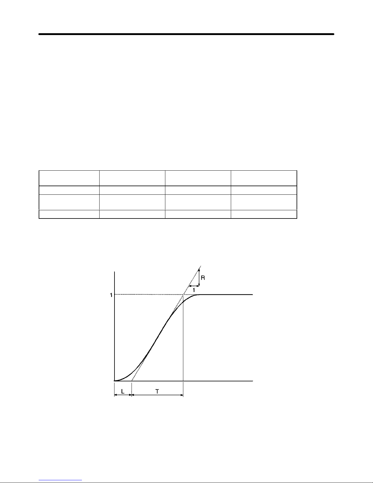
3-37
Note Measure the response waveform so that the timing of the step input will be known.
2. Calculation of PID Parameters
S Draw a tangent line contacting with the steepest inclining point of the response waveform.
S Measurement of R
Measure the gradient of the tangent line provided that the set point is 1.
S Measurement of L
Measure
the required time (seconds) between the origin and the point of intersection of the tan
-
gent line and time axis.
S Measurement of T
Measure
the required
time (seconds) between the point of intersection of the tangent line and time
axis and the point of intersection of the tangent line and set point line.
S PID Parameters
The following can be calculated from the R, L, and T values as “rules of thumb.”
Control Proportional gain (P)
(n086)
Integral time (I)
(n087)
Derivative time (D)
(n088)
Proportional control 0.3/RL --- --Proportional/Integral
control
0.35/RL 1.2T ---
PID control 0.6/RL T 0.5L
Note 1. Obtain
PID parameter values from the above
method, set the PID parameters, and tune in the
PID parameter values exactly.
Note 2. PID
parameter values
obtained from the above method may not be optimum values if the fric
-
tion factor of the mechanical system is large.
Response
Time
Set
point
D Manual Adjustments
Take
the following steps
to adjust the PID parameter values of the Inverter performing PID control by
measuring the response waveform.
1. Set n084 to 2 or 1 so that the Inverter will perform PID control.
Preparing for Operation Chapter 3
Page 95
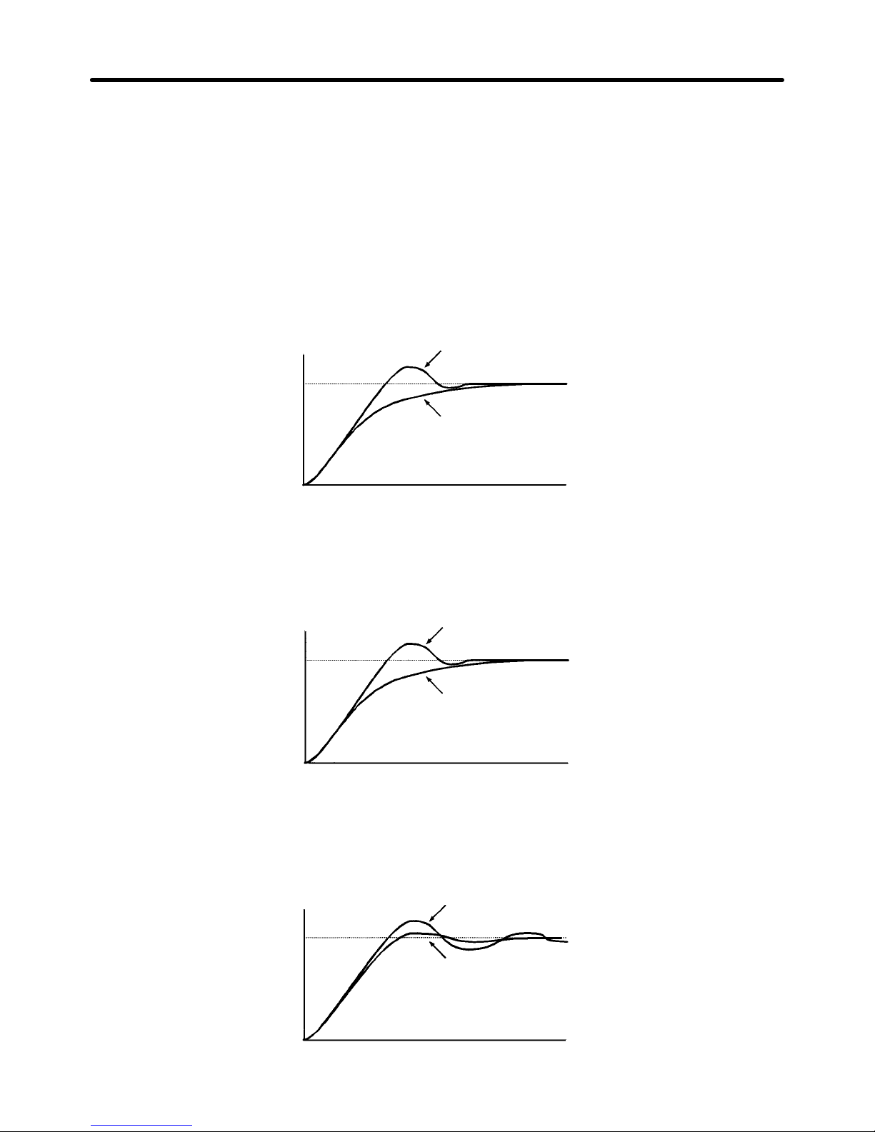
3-38
2. Increase the proportional gain with n086 within a range causing no vibration.
3. Increase the integral time with n087 within a range causing no vibration.
4. Increase the derivative time with n088 within a range causing no vibration.
H PID Fine Tuning
Refer to the following to tune in PID parameters exactly.
D Suppression of Overshooting
Set
the derivative time to a smaller value and the integral time to a larger value if overshooting results.
Response
Before fine tuning
After fine tuning
Time
D Prompt Control
Set
the integral time to a smaller value and the derivative time to a large value for the prompt control of
overshooting.
Response
Before
fine tuning
After fine tuning
Time
D Suppression of Long-cycle Vibration
Vibration with a wavelength longer than the integral time results from excessive integral control. The
vibration can be suppressed by setting the integral time to a larger value.
Response
Before
fine tuning
After fine tuning
Time
Preparing for Operation Chapter 3
Page 96

3-39
D Suppression of Short-cycle Vibration
Vibration
with a wavelength almost as long as the derivative time results from
excessive derivative con
-
trol.
The vibration can be suppressed by setting the derivative time to a smaller value. Set the propor
-
tional
gain to a smaller value or the PID primary delay constant to a larger value if the vibration cannot be
suppressed after the derivative time is set to 0.00.
Response
Before
fine-tuning
After fine-tuning
Time
Preparing for Operation Chapter 3
Page 97

3-40
3-5-3 List of Parameters
Values in brackets [ ] are default-set values.
Note Parameters that can be changed while the Inverter is running are indicated in bold type.
H Group 1: n001 to n034
Function No. Name Description Setting
range
Refer-
ence
page
Parameter
group selection
n001 Parameter
write prohibit
selection/Parameter initialization
0: The parameters n001 can be set and
checked and the parameters n002 to
n108 can be only checked.
The speed and direction of the Digital
Operator can be set.)
1: The parameters of group 1 (i.e., n001
to n034) can be set and checked and
the parameters of groups 2 and 3 (i.e.,
n035 to n049 and n050 to n108) can be
only checked.
2: The parameters of groups 1 and 2 can
be set and checked and the parame-
p
0 to 7
[1]
3-13
Parameter initialization
t
ers of group 3 can onlybe checked.
3: The parameters of groups 1, 2, and 3
can be set and checked.
6: All parameters will be set to default-set
values.
7: All parameters will be initialized with a
three-wire sequence.
Note When parameter initialization is per-
formed by setting to 6 or 7, the Forward/Reverse rotation selection
(n005) is not initialized. (It is only initialized when a CPF4 error is
detected.)
Operation
mode selection
n002 Operation
mode selection
Selects method to input run command and
frequency reference.
Run command Frequency reference
0: Digital Operator Digital Operator
1:
Control
circuit terminals
Digital Operator
2: Digital Operator Control circuit terminals
3:
Control
circuit terminals
Control circuit terminals
0 to 3
[3]
3-13
Input voltage
selection
n003 Input voltage
selection
(see note)
Set Inverter input voltage in 1-V units. 150.0
to
255.0
[200.0]
3-23
Interruption
mode selection
n004 Interruption
mode selection
0: Deceleration stop
1: Free running stop
2: Free running stop 1 with timer. The run
command during deceleration time 1 or
2 will be ignored.
3: Free running stop 2 with timer. The
constant run command is valid. The
motor will start running after deceleration time 1 or 2 passes.
0 to 3
[0]
3-23
Note With
400-V Inverters, the setting range
upper limits and default settings are double those shown
in the table.
Preparing for Operation Chapter 3
Page 98

3-41
Function No. Name Description Setting
range
Refer-
ence
page
Motor rotation
direction selection
n005 Forward/Re-
verse rotation
selection
0: When the forward rotation command is
input, the motor seen from the load
side rotates counterclockwise.
1: When the forward rotation command is
input, the motor seen from the load
side rotates clockwise.
Note This
parameter is
not initialized when
parameter initialization is performed
by
setting n001 to 6 or 7. (It is only
ini
tialized when a CPF4 error is
detected.)
0, 1 [0] 3-17
n006 Reverse rota-
tion-inhibit
selection
0: The motor can rotate in reverse.
1: The motor cannot rotate in reverse.
0, 1 [0] 3-17
Preparing for Operation Chapter 3
Page 99

3-42
Function No. Name Description Setting
range
Refer-
ence
page
Digital Operator function selection
n007 Operation
direction
selection key
permit/inhibit
0: Inhibits Operation Mode Selection Key
from functioning.
1: Permits Operation Mode Selection Key
to function.
0, 1 [1] 3-57
n008 Stop Key func-
tion selection
0: The STOP/RESET Key will function
only when the Inverter is running with
the run command through the Digital
Operator.
1: The STOP/RESET Key will function
anytime.
0, 1 [1] 3-58
n009 Frequency ref-
erence setting
selection
0: Permits frequency reference set with
the Digital Operator to be valid without
Enter Key input.
1: Permits frequency reference set with
the Digital Operator to be valid with Enter Key input.
0, 1 [1] 3-58
V/f pattern
selection
n010 V/f pattern
selection
0to E: Selects from 15 fixed V/f patterns.
F: Selects optional V/f pattern with n012
to n018 settings.
0 to F [1] 3-58
n011 Rated input
voltage of motor
(see note)
Set rated input voltage of motor with 1 V
units.
150.0 to
255.0
[200.0]
3-60
V/f pattern
selection
n012 Maximum fre-
quency
(FMAX)
Voltage
(V)
50.0 to
400.0 [60.0]
3-60
n013 Maximum volt-
age (VMAX)
(see note)
0.1 to 255.0
[200.0] (See
note 1.)
3-60
n014 Maximum volt-
age frequency
(FA)
The V/f pattern will be a straight line if
Frequency
(Hz)
0.2 to 400.0
[60.0]
3-61
n015 Intermediate
output frequency (FB)
g
there is no difference between n015 and
n017 in set value, in which case the set
value of n016 will be ignored.
0.1 to 399.9
[3.0]
3-61
n016 Intermediate
output frequency voltage (VC)
(see note)
0.1 to 255.0
[15.0] (See
note 1, 2.)
3-61
n017 Minimum out-
put frequency
(FMIN)
0.1 to 10.0
[1.5]
3-61
n018 Minimum out-
put frequency
voltage
(VMIN)
(see note)
0.1 to 50.0
[10.0] (See
note 1, 2.)
3-61
Note 1. With 400-V Inverters, the setting range upper limits and default settings are double those
shown in the table.
Note 2. The default settings for Inverters of 55 kW or more are as follows:
n016 = 12.0/24.0, n018 = 6.0/12.0
Preparing for Operation Chapter 3
Page 100

3-43
Function No. Name Description Setting
range
Refer-
ence
page
Acceleration/
Deceleration
time selection
n019 Acceleration
time 1
The time required for the output frequency
to be 100% from 0% of the maximum frequency.
0.0 to
3,600
[10.0]
3-61
n020 Deceleration
time 1
The time required for the output frequency
to be 0% from 100% of the maximum frequency.
0.0 to
3,600
[10.0]
3-61
n021 Acceleration
time 2
Valid if acceleration/deceleration time
switching command is selected for multifunction input.
0.0 to
3,600
[10.0]
3-61
n022 Deceleration
time 2
Valid if acceleration/deceleration time
switching command is selected for multifunction input.
0.0 to
3,600
[10.0]
3-62
S-shaped characteristic time
selection
n023 S-shaped char-
acteristic time
selection
0: No s-shaped characteristic time
1: 0.2 s
2: 0.5 s
3: 1.0 s
0 to 3
[1]
3-62
Frequency reference selection
n024 Unit of frequen-
cy reference
0: 0.1-Hz units
1: 0.1% units
2to 39: r/min
(r/min = 120 x frequency/n024
Set n024 to the number of poles of
the motor.)
40 to 3,999: Determine the display meth-
od of the maximum frequency
set with n012.
Example: Set n024 to 1100
so that “10.0” will be displayed at the maximum frequency.
0 to
3,999
[0]
3-62
Frequency reference selection
n025 Frequency ref-
erence 1
Set frequency reference using the unit set
with n024.
0 to
maximum
frequency
[6.0]
3-63
n026 Frequency ref-
erence 2
Frequency reference with multi-step speed
command 1 turned ON.
0 to
maxi-
3-63
n027 Frequency ref-
erence 3
Frequency reference with multi-step speed
command 2 turned ON.
a
mum
fre-
3-63
n028 Frequency ref-
erence 4
Frequency reference with multi-step speed
command 1 and 2 turned ON.
quency
[0.0]
3-63
n029 Inching fre-
quency reference
Frequency reference with inching command turned ON.
0 to
maximum
frequency
[6.0]
3-63
Output frequency limit
selection
n030 Output frequen-
cy upper limit
Set output frequency upper limit with 1%
units based on max. frequency set with
n012 as 100%.
0 to
109
[100]
3-63
n031 Output frequen-
cy lower limit
Set output frequency lower limit with 1%
units based on max. frequency set with
n012 as 100%.
0 to
100 [0]
3-63
Preparing for Operation Chapter 3
 Loading...