

Page 1

Cat. No. I516-E1-05
USER’S MANUAL
SYSDRIVE 3G3FV
High-function General-purpose Inverter
Page 2

Thank you for choosing this SYSDRIVE 3G3FV-series product. Proper use and
handling of the product will ensure proper product performance, will length
product life, and may prevent possible accidents.
Please read this manual thoroughly and handle and operate the product with care.
1. To ensure safe and proper use of the OMRON Inverters, please read this USER’S MANUAL (Cat.
No. I516-E1) to gain sufficient knowledge of the devices, safety information, and precautions before actual use.
2. The products are illustrated without covers and shieldings for closer look in this USER’S MANUAL. For actual use of the products, make sure to use the covers and shieldings as specified.
3. This USER’S MANUAL and other related user’s manuals are to be delivered to the actual end
users of the products.
4. Please keep this manual close at hand for future reference.
5. If the product has been left unused for a long time, please inquire at our sales representative.
NOTICE
1. This manual describes the functions of the product and relations with other products. You
should assume that anything not described in this manual is not possible.
2. Although care has been given in documenting the product, please contact your OMRON
representative if you have any suggestions on improving this manual.
3. The product contains potentially dangerous parts under the cover. Do not attempt to open
the cover under any circumstances. Doing so may result in injury or death and may damage
the product. Never attempt to repair or disassemble the product.
4. We recommend that you add the following precautions to any instruction manuals you prepare for the system into which the product is being installed.
Precautions on the dangers of high-voltage equipment.
Precautions on touching the terminals of the product even after power has been
turned off. (These terminals are live even with the power turned off.)
5. Specifications and functions may be changed without notice in order to improve product
performance.
Items to Check when Unpacking
Check the following items when removing the product from the package:
Has the correct product been delivered (i.e., the correct model number and speci-
fications)? Check the nameplate as shown below.
Inverter model
Input specification
Output specification
Has the product been damaged in shipping?
Are any screws or bolts loose?
Page 3

Notice:
OMRON products are manufactured for use according to proper procedures by a qualified
operator and only for the purposes described in this manual.
The following conventions are used to indicate and classify precautions in this manual.
Always heed the information provided with them. Failure to heed precautions can result in
injury to people or damage to property.
!
DANGER Indicates an imminently hazardous situation which, if not avoided, will result in death
or serious injury. Additionally, there may be severe property damage.
WARNING Indicates a potentially hazardous situation which, if not avoided, could result in death
!
or serious injury. Additionally, there may be severe property damage.
Caution Indicates a potentially hazardous situation which, if not avoided, may result in minor
!
or moderate injury, or property damage.
OMRON Product References
All OMRON products are capitalized in this manual. The word “Unit” is also capitalized when
it refers to an OMRON product, regardless of whether or not it appears in the proper name
of the product.
The abbreviation “Ch,” which appears in some displays and on some OMRON products,
often means “word” and is abbreviated “Wd” in documentation in this sense.
The abbreviation “PC” means Programmable Controller and is not used as an abbreviation
for anything else.
Visual Aids
The following headings appear in the left column of the manual to help you locate different
types of information.
Note Indicates information of particular interest for efficient and convenient operation of the product.
OMRON, 1996
All rights reserved. No part of this publication may be reproduced, stored in a retrieval system, or transmitted,
in any form, or by any means, mechanical, electronic, photocopying, recording, or otherwise, without the prior
written permission of OMRON.
No patent liability is assumed with respect to the use of the information contained herein. Moreover, because
OMRON is constantly striving to improve its high-quality products, the information contained in this manual
is subject to change without notice. Every precaution has been taken in the preparation of this manual. Nevertheless, OMRON assumes no responsibility for errors or omissions. Neither is any liability assumed for damages resulting from the use of the information contained in this publication.
Page 4

General Precautions
Observe the following precautions when using the SYSDRIVE Inverters and peripheral
devices.
This manual may include illustrations of the product with protective covers removed in order
to describe the components of the product in detail. Make sure that these protective covers
are on the product before use.
Consult your OMRON representative when using the product after a long period of storage.
WARNING Do not touch the inside of the Inverter. Doing so may result in electrical shock.
!
WARNING Operation, maintenance, or inspection must be performed after turning OFF the
!
power supply, confirming that the CHARGE indicator (or status indicators) are OFF,
and after waiting for the time specified on the front cover. Not doing so may result in
electrical shock.
WARNING Do not damage, pull on, apply stress to, place heavy objects on, or pinch the cables.
!
Doing so may result in electrical shock.
WARNING Do not touch the rotating parts of the motor under operation. Doing so may result in
!
injury.
WARNING Do not modify the product. Doing so may result in injury or damage to the product.
!
Caution Do not store, install, or operate the product in the following places. Doing so may
!
result in electrical shock, fire or damage to the product.
Locations subject to direct sunlight.
Locations subject to temperatures or humidity outside the range specified in the
specifications.
Locations subject to condensation as the result of severe changes in temperature.
Locations subject to corrosive or flammable gases.
Locations subject to exposure to combustibles.
Locations subject to dust (especially iron dust) or salts.
Locations subject to exposure to water, oil, or chemicals.
Locations subject to shock or vibration.
Caution Do not touch the Inverter radiator, regenerative resistor, or Servomotor while the
!
power is being supplied or soon after the power is turned OFF . Doing so may result in
a skin burn due to the hot surface.
Caution Do not conduct a dielectric strength test on any part of the Inverter. Doing so may
!
result in damage to the product or malfunction.
Caution Take appropriate and sufficient countermeasures when installing systems in the fol-
!
lowing locations. Not doing so may result in equipment damage.
Locations subject to static electricity or other forms of noise.
Locations subject to strong electromagnetic fields and magnetic fields.
Locations subject to possible exposure to radioactivity.
Locations close to power supplies.
Page 5

Transportation Precautions
Caution Do not hold by front cover or panel , instead, hold by the radiation fin (heat sink) while
!
transporting the product. Doing so may result in injury.
Caution Do not pull on the cables. Doing so may result in damage to the product or malfunc-
!
tion.
Caution Use the eye-bolts only for transporting the Inverter. Using them for transporting th e
!
machinery may result in injury or malfunction.
Installation Precautions
WARNING Provide an appropriate stopping device on the machine side to secure safety. (A
!
holding brake is not a stopping device for securing safety.) Not doing so may result in
injury.
WARNING Provide an external emergency stopping device that allows an instantaneous stop of
!
operation and power interruption. Not doing so may result in injury.
Caution Be sure to install the product in the correct direction and provide specified clear-
!
ances between the Inverter and control panel or with other devices. Not doing so
may result in fire or malfunction.
Caution Do not allow foreign objects to enter inside the product. Doing so may result in fire or
!
malfunction.
Caution Do not apply any strong impact. Doing so may result in damage to the product or
!
malfunction.
Wiring Precautions
WARNING Wiring must be performed only after confirming that the power supply has been
!
turned OFF. Not doing so may result in electrical shock.
WARNING Wiring must be performed by authorized personnel. Not doing so may result in
!
electrical shock or fire.
WARNING Be sure to confirm operation only after wiring the emergency stop circuit. Not doing
!
so may result in injury.
WARNING Always connect the ground terminals to a ground of 100 Ω or less for the 200-V AC
!
class, or 1 0 Ω or less for the 400-V AC class. Not connecting to a proper ground may
result in electrical shock.
Page 6

Caution Install external breakers and take other safety measures against short-circuiting in
!
external wiring. Not doing so may result in fire.
Caution Confirm that the rated input voltage of the Inverter is the same as the AC power sup-
!
ply voltage. An incorrect power supply may result in fire, injury, or malfunction.
Caution Connect the Braking Resistor and Braking Resistor Unit as specified in the manual.
!
Not doing so may result in fire.
Caution Be sure to wire correctly and securely. Not doing so may result in injury or damage to
!
the product.
Caution Be sure to firmly tighten the screws on the terminal block. Not doing so may result in
!
fire, injury, or damage to the product.
Caution Do not connect an AC power to the U, V, or W output. Doing so may result in damage
!
to the product or malfunction.
Operation and Adjustment Precautions
WARNING Turn ON the input power supply only after mounting the front cover, terminal covers,
!
bottom cover, Operator, and optional items. Not doing so may result in electrical
shock.
WARNING Do not remove the front cover, terminal covers, bottom cover, Operator, or optional
!
items while the power is being supplied. Doing so may result in electrical shock or
damage to the product.
WARNING Do not operate the Operator or switches with wet hands. Doing so may result in
!
electrical shock.
WARNING Do not touch the inside of the Inverter. Doing so may result in electrical shock.
!
WARNING Do not come close to the machine when using the error retry function because the
!
machine may abruptly start when stopped by an alarm. Doing so may result in injury.
WARNING Do not come close to the machine immediately after resetting momentary power
!
interruption to avoid an unexpected restart (if operation is set to be continued in the
processing selection function after momentary power interruption is reset). Doing so
may result in injury.
WARNING Provide a separate emergency stop switch because the STOP Key on the Operator
!
is valid only when function settings are performed. Not doing so may result in injury.
Page 7

WARNING Be sure to confirm that the RUN signal is turned OFF before turning ON the power
!
supply, resetting the alarm, or switching the LOCAL/REMOTE selector. Doing so
while the RUN signal is turned ON may result in injury.
Caution Be sure to confirm permissible ranges of motors and machines before operation
!
because the Inverter speed can be easily changed from low to high. Not doing so
may result in damage to the product.
Caution Provide a separate holding brake when necessary. Not doing so may result in injury.
!
Caution Do not perform a signal check during operation. Doing so may result in injury or dam-
!
age to the product.
Caution Do not carelessly change settings. Doing so may result in injury or damage to the
!
product.
Maintenance and Inspection Precautions
WARNING Do not touch the Inverter terminals while the power is being supplied.
!
WARNING Maintenance or inspection must be performed only after turning OFF the power
!
supply, confirming that the CHARGE indicator (or status indicators) is turned OFF,
and after waiting for the time specified on the front cover. Not doing so may result in
electrical shock.
WARNING Maintenance, inspection, or parts replacement must be performed by authorized
!
personnel. Not doing so may result in electrical shock or injury.
WARNING Do not attempt to take the Unit apart or repair. Doing either of these may result in
!
electrical shock or injury.
Caution Carefully handle the Inverter because it uses semiconductor elements. Careless
!
handling may result in malfunction.
Caution Do not change wiring, disconnect connectors, the Operator, or optional items, or
!
replace fans while power is being supplied. Doing so may result in injury, damage to
the product, or malfunction.
Page 8

Warning Labels
Warning labels are pasted on the product as shown in the following illustration. Be sure to
follow the instructions given there.
Warning Labels
Contents of Warning
Page 9

Checking Before Unpacking
Checking the Product
On delivery, always check that the delivered product is the SYSDRIVE 3G3MV Inverter that you
ordered.
Should you find any problems with the product, immediately contact your nearest local sales
representative.
Checking the Nameplate
Inverter model
Input specifications
Output specifications
Checking the Model
3G3FV-A2037-CUE
Specifications
None Japanese model
-E English model
-CE Model conforming to EN standards
-CUE Model conforming to EN and UL/cUL
standards
3G3FV-A2001
Specifications
Maximum applicable motor capacity
Voltage class
Installation type
Series name: 3G3MV Series
Page 10

Maximum Applicable Motor Capacity
004 0.4 kW
007 0.75 kW
015 1.5 kW
022 2.2 kW
037 3.7 kW
055 5.5 kW
075 7.5 kW
110 11 kW
150 15 kW
185 18.5 kW
220 22 kW
300 30 kW
370 37 kW
450 45 kW
550 55 kW
750 75 kW
11K 110 kW
16K 160 kW
18K 185 kW
22K 220 kW
30K 300 kW
Voltage Class
2 Three-phase 200-V AC input (200-V class)
4 Three-phase 400-V AC input (400-V class)
Installation Type
A Panel-mounting (IP10 min.) or closed wall-mounting models
C Closed wall-mounting models (IP00 min.)
Checking for Damage
Check the overall appearance and check for damage or scratches resulting from transportation.
Checking the Accessories
Note that this manual is the only accessory provided with the 3G3MV. Set screws and other necessary
parts must be provided by the user.
Page 11

About this Manual
This manual is divided into the chapters described in the following table. Information is organized by
application area to enable you to use the manual more efficiently.
Chapter Contents
Chapter 1 Overview Describes features and nomenclature. Also describes new functions.
Chapter 2 Installation Provides information required for system design, such as product
dimensions, installation dimensions, peripheral device design
information, and peripheral device selection information.
Chapter 3 Preparing for Operation Describes nomenclature, Digital Operator procedures, such as key
operations, for operating and monitoring Inverters, and mode contents
and configuration.
Chapter 4 Trial Operation Describes the method for controlling operation through a Digital
Operator to perform trial operation of the system.
Chapter 5 Basic Operation Describes basic Inverter control functions for users not familiar with
Inverters. The functions that must be understood to drive a motor with
an Inverter are described. Each of the four control modes of the
3G3FV-series Inverters is described in order alone with the settings
required for all modes and individual modes. Refer to the information
for all control modes and then to items required for the control mode
you will be using.
Chapter 6 Advanced Operation Describes all of the functions provided by the Inverter. These functions
will enable more advanced applications, and includes functions that
will improve motor control through the Inverter, such as
responsiveness (torque characteristics), increasing speed accuracy,
PID control, torque limits, torque controls, overtorque detection,
protective functions, and other functions. Each of the four control
modes of the 3G3FV-series Inverters is described in order alone with
the characteristics of each mode and fountains common to all modes.
Refer to the information for all control modes and then to items
required for the control mode you will be using.
Chapter 7 List of Parameters Lists basic information on Inverter parameters as a reference for users
already familiar with Inverter operation. Parameters are listed in order
with the page numbers of further information for easy reference.
Chapter 8 Maintenance Operations Provides maintenance, inspection, fault analysis, and troubleshooting
information required to deal with problems that may occur during
operation.
Chapter 9 Specifications Provides Inverter specifications, as well as the specifications and
dimensions of peripheral devices.
Page 12

Read and Understand this Manual
Á
Á
Á
Á
Á
Á
Á
Á
Á
Á
Á
Á
Á
Á
Á
Á
Please read and understand this manual before using the product. Please consult your OMRON
representative if you have any questions or comments.
Warranty and Limitations of Liability
WARRANTY
OMRON’s exclusive warranty is that the products are free from defects in materials and workmanship for
БББББББББББББББББББББББББББББББ
a period of one year (or other period if specified) from date of sale by OMRON.
БББББББББББББББББББББББББББББББ
OMRON MAKES NO WARRANTY OR REPRESENTATION, EXPRESS OR IMPLIED, REGARDING
БББББББББББББББББББББББББББББББ
NON–INFRINGEMENT, MERCHANTABILITY, OR FITNESS FOR P ARTICULAR PURPOSE OF THE
БББББББББББББББББББББББББББББББ
PRODUCTS. ANY BUYER OR USER ACKNOWLEDGES THAT THE BUYER OR USER ALONE HAS
БББББББББББББББББББББББББББББББ
DETERMINED THAT THE PRODUCTS WILL SUITABLY MEET THE REQUIREMENTS OF THEIR
INTENDED USE. OMRON DISCLAIMS ALL OTHER WARRANTIES, EXPRESS OR IMPLIED.
БББББББББББББББББББББББББББББББ
БББББББББББББББББББББББББББББББ
LIMITATIONS OF LIABILITY
OMRON SHALL NOT BE RESPONSIBLE FOR SPECIAL, INDIRECT, OR CONSEQUENTIAL
БББББББББББББББББББББББББББББББ
DAMAGES, LOSS OF PROFITS OR COMMERCIAL LOSS IN ANY WAY CONNECTED WITH THE
БББББББББББББББББББББББББББББББ
PRODUCTS, WHETHER SUCH CLAIM IS BASED ON CONTRACT, WARRANTY, NEGLIGENCE, OR
БББББББББББББББББББББББББББББББ
STRICT LIABILITY.
БББББББББББББББББББББББББББББББ
In no event shall the responsibility of OMRON for any act exceed the individual price of the product on
БББББББББББББББББББББББББББББББ
which liability is asserted.
БББББББББББББББББББББББББББББББ
IN NO EVENT SHALL OMRON BE RESPONSIBLE FOR WARRANTY, REPAIR, OR OTHER CLAIMS
БББББББББББББББББББББББББББББББ
REGARDING THE PRODUCTS UNLESS OMRON’S ANALYSIS CONFIRMS THAT THE PRODUCTS
БББББББББББББББББББББББББББББББ
WERE PROPERLY HANDLED, STORED, INSTALLED, AND MAINTAINED AND NOT SUBJECT TO
БББББББББББББББББББББББББББББББ
CONTAMINATION, ABUSE, MISUSE, OR INAPPROPRIATE MODIFICATION OR REPAIR.
Page 13

Application Considerations
Á
Á
Á
Á
Á
Á
Á
Á
Á
Á
Á
Á
Á
Á
Á
Á
Á
Á
Á
Á
Á
SUITABILITY FOR USE
OMRON shall not be responsible for conformity with any standards, codes, or regulations that apply to
БББББББББББББББББББББББББББББББ
the combination of products in the customer’s application or use of the products.
БББББББББББББББББББББББББББББББ
At the customer’s request, OMRON will provide applicable third party certification documents identifying
БББББББББББББББББББББББББББББББ
ratings and limitations of use that apply to the products. This information by itself is not sufficient for a
БББББББББББББББББББББББББББББББ
complete determination of the suitability of the products in combination with the end product, machine,
БББББББББББББББББББББББББББББББ
system, or other application or use.
БББББББББББББББББББББББББББББББ
The following are some examples of applications for which particular attention must be given. This is not
БББББББББББББББББББББББББББББББ
intended to be an exhaustive list of all possible uses of the products, nor is it intended to imply that the
БББББББББББББББББББББББББББББББ
uses listed may be suitable for the products:
БББББББББББББББББББББББББББББББ
• Outdoor use, uses involving potential chemical contamination or electrical interference, or conditions
БББББББББББББББББББББББББББББББ
or uses not described in this manual.
БББББББББББББББББББББББББББББББ
• Nuclear energy control systems, combustion systems, railroad systems, aviation systems, medical
БББББББББББББББББББББББББББББББ
equipment, amusement machines, vehicles, safety equipment, and installations subject to separate
БББББББББББББББББББББББББББББББ
industry or government regulations.
БББББББББББББББББББББББББББББББ
• Systems, machines, and equipment that could present a risk to life or property.
БББББББББББББББББББББББББББББББ
Please know and observe all prohibitions of use applicable to the products.
БББББББББББББББББББББББББББББББ
БББББББББББББББББББББББББББББББ
NEVER USE THE PRODUCTS FOR AN APPLICATION INVOL VING SERIOUS RISK TO LIFE OR
БББББББББББББББББББББББББББББББ
PROPERTY WITHOUT ENSURING THAT THE SYSTEM AS A WHOLE HAS BEEN DESIGNED TO
ADDRESS THE RISKS, AND THAT THE OMRON PRODUCTS ARE PROPERL Y RATED AND
БББББББББББББББББББББББББББББББ
INSTALLED FOR THE INTENDED USE WITHIN THE OVERALL EQUIPMENT OR SYSTEM.
БББББББББББББББББББББББББББББББ
PROGRAMMABLE PRODUCTS
OMRON shall not be responsible for the user’s programming of a programmable product, or any
БББББББББББББББББББББББББББББББ
consequence thereof.
Page 14

Disclaimers
Á
Á
Á
Á
Á
Á
Á
Á
Á
Á
Á
Á
Á
CHANGE IN SPECIFICATIONS
БББББББББББББББББББББББББББББББ
Product specifications and accessories may be changed at any time based on improvements and other
reasons.
БББББББББББББББББББББББББББББББ
БББББББББББББББББББББББББББББББ
It is our practice to change model numbers when published ratings or features are changed, or when
significant construction changes are made. However, some specifications of the products may be
БББББББББББББББББББББББББББББББ
changed without any notice. When in doubt, special model numbers may be assigned to fix or establish
БББББББББББББББББББББББББББББББ
key specifications for your application on your request. Please consult with your OMRON representative
БББББББББББББББББББББББББББББББ
at any time to confirm actual specifications of purchased products.
БББББББББББББББББББББББББББББББ
DIMENSIONS AND WEIGHTS
Dimensions and weights are nominal and are not to be used for manufacturing purposes, even when
tolerances are shown.
БББББББББББББББББББББББББББББББ
PERFORMANCE DATA
Performance data given in this manual is provided as a guide for the user in determining suitability and
БББББББББББББББББББББББББББББББ
does not constitute a warranty. It may represent the result of OMRON’s test conditions, and the users
БББББББББББББББББББББББББББББББ
must correlate it to actual application requirements. Actual performance is subject to the OMRON
БББББББББББББББББББББББББББББББ
Warranty and Limitations of Liability.
БББББББББББББББББББББББББББББББ
The information in this manual has been carefully checked and is believed to be accurate; however, no
responsibility is assumed for clerical, typographical, or proofreading errors, or omissions.
БББББББББББББББББББББББББББББББ
ERRORS AND OMISSIONS
Page 15

How to Change the Digital Operator Display from
Japanese to English
If the Digital Operator displays messages in Japanese, change to the English mode using
the following steps.
(This manual provides descriptions for the English mode.)
Power ON
<Ć3J=3 <Z2
U1Ć01= 0.00 HZ
FV* S0D^>]@8 *
D^W2L^ S0D^
FV* S0D^>]@8 *
6]7.3>/C2
9^]:^>]@8
FN]:^
A1Ć00= 1 **
FN]:^
A1Ć00= 0
English
Entry Accepted
** Main Menu **
Operation
Select Language
English
Page 16

Table of Contents
Chapter 1. Introduction 1-1. . . . . . . . . . . . . . . . . . . . . . . . . . . . . . . . . . . . .
1-1 Functions 1-2. . . . . . . . . . . . . . . . . . . . . . . . . . . . . . . . . . . . . . . . . . . . . . . . . . . . . . . . . . . . . . . . . .
1-2 Nomenclature 1-8. . . . . . . . . . . . . . . . . . . . . . . . . . . . . . . . . . . . . . . . . . . . . . . . . . . . . . . . . . . . . . .
1-3 New Functions 1-11. . . . . . . . . . . . . . . . . . . . . . . . . . . . . . . . . . . . . . . . . . . . . . . . . . . . . . . . . . . . . .
1-3-1 Software Ver. VSG101040 1-11. . . . . . . . . . . . . . . . . . . . . . . . . . . . . . . . . . . . . . . . . . . . . .
1-3-2 Software Ver. VSG101043 1-13. . . . . . . . . . . . . . . . . . . . . . . . . . . . . . . . . . . . . . . . . . . . . .
1-3-3 Software Ver. VSG101113 1-14. . . . . . . . . . . . . . . . . . . . . . . . . . . . . . . . . . . . . . . . . . . . . .
1-3-4 Software Ver. VSG101114 1-17. . . . . . . . . . . . . . . . . . . . . . . . . . . . . . . . . . . . . . . . . . . . . .
Chapter 2. Installation 2-1. . . . . . . . . . . . . . . . . . . . . . . . . . . . . . . . . . . . . .
2-1 Mounting 2-2. . . . . . . . . . . . . . . . . . . . . . . . . . . . . . . . . . . . . . . . . . . . . . . . . . . . . . . . . . . . . . . . . .
2-1-1 Dimensions 2-2. . . . . . . . . . . . . . . . . . . . . . . . . . . . . . . . . . . . . . . . . . . . . . . . . . . . . . . . . .
2-1-2 Installation Conditions 2-8. . . . . . . . . . . . . . . . . . . . . . . . . . . . . . . . . . . . . . . . . . . . . . . . .
2-2 Wiring 2-11. . . . . . . . . . . . . . . . . . . . . . . . . . . . . . . . . . . . . . . . . . . . . . . . . . . . . . . . . . . . . . . . . . . .
2-2-1 Removing and Mounting the Front Cover 2-12. . . . . . . . . . . . . . . . . . . . . . . . . . . . . . . . . .
2-2-2 Terminals 2-14. . . . . . . . . . . . . . . . . . . . . . . . . . . . . . . . . . . . . . . . . . . . . . . . . . . . . . . . . . . .
2-2-3 Standard Connection Diagram 2-18. . . . . . . . . . . . . . . . . . . . . . . . . . . . . . . . . . . . . . . . . . .
2-2-4 Wiring Around the Main Circuit 2-23. . . . . . . . . . . . . . . . . . . . . . . . . . . . . . . . . . . . . . . . .
2-2-5 Wiring Control Circuit Terminals 2-39. . . . . . . . . . . . . . . . . . . . . . . . . . . . . . . . . . . . . . . . .
2-2-6 Installing and Wiring PG Speed Control Cards 2-40. . . . . . . . . . . . . . . . . . . . . . . . . . . . . .
Chapter 3. Preparing for Operation 3-1. . . . . . . . . . . . . . . . . . . . . . . . . . .
3-1 Using the Digital Operator 3-2. . . . . . . . . . . . . . . . . . . . . . . . . . . . . . . . . . . . . . . . . . . . . . . . . . . .
3-2 Modes 3-3. . . . . . . . . . . . . . . . . . . . . . . . . . . . . . . . . . . . . . . . . . . . . . . . . . . . . . . . . . . . . . . . . . . . .
3-3 Operation Mode 3-10. . . . . . . . . . . . . . . . . . . . . . . . . . . . . . . . . . . . . . . . . . . . . . . . . . . . . . . . . . . . .
3-4 Initialize Mode 3-18. . . . . . . . . . . . . . . . . . . . . . . . . . . . . . . . . . . . . . . . . . . . . . . . . . . . . . . . . . . . . .
3-5 Program Mode 3-25. . . . . . . . . . . . . . . . . . . . . . . . . . . . . . . . . . . . . . . . . . . . . . . . . . . . . . . . . . . . . .
3-6 Auto-tuning Mode 3-28. . . . . . . . . . . . . . . . . . . . . . . . . . . . . . . . . . . . . . . . . . . . . . . . . . . . . . . . . . .
3-7 Modified Constants Mode 3-30. . . . . . . . . . . . . . . . . . . . . . . . . . . . . . . . . . . . . . . . . . . . . . . . . . . . .
3-8 Operation Mode Selection Key and Local/Remote Selection Input 3-31. . . . . . . . . . . . . . . . . . . . .
Chapter 4. Trial Operation 4-1. . . . . . . . . . . . . . . . . . . . . . . . . . . . . . . . . . .
4-1 Procedure 4-3. . . . . . . . . . . . . . . . . . . . . . . . . . . . . . . . . . . . . . . . . . . . . . . . . . . . . . . . . . . . . . . . . .
4-2 Operation Example 4-5. . . . . . . . . . . . . . . . . . . . . . . . . . . . . . . . . . . . . . . . . . . . . . . . . . . . . . . . . .
4-2-1 Power Connection 4-5. . . . . . . . . . . . . . . . . . . . . . . . . . . . . . . . . . . . . . . . . . . . . . . . . . . . .
4-2-2 Checking the Display Status 4-5. . . . . . . . . . . . . . . . . . . . . . . . . . . . . . . . . . . . . . . . . . . . .
4-2-3 Initializing Parameters 4-6. . . . . . . . . . . . . . . . . . . . . . . . . . . . . . . . . . . . . . . . . . . . . . . . .
4-2-4 Setting Input Voltage 4-6. . . . . . . . . . . . . . . . . . . . . . . . . . . . . . . . . . . . . . . . . . . . . . . . . .
4-2-5 Auto-tuning 4-8. . . . . . . . . . . . . . . . . . . . . . . . . . . . . . . . . . . . . . . . . . . . . . . . . . . . . . . . . .
4-2-6 No-load Operation 4-10. . . . . . . . . . . . . . . . . . . . . . . . . . . . . . . . . . . . . . . . . . . . . . . . . . . .
4-2-7 Actual Load Operation 4-11. . . . . . . . . . . . . . . . . . . . . . . . . . . . . . . . . . . . . . . . . . . . . . . . .
Chapter 5. Basic Operation 5-1. . . . . . . . . . . . . . . . . . . . . . . . . . . . . . . . . .
5-1 Common Settings 5-2. . . . . . . . . . . . . . . . . . . . . . . . . . . . . . . . . . . . . . . . . . . . . . . . . . . . . . . . . . . .
5-1-1 Setting the Access Level and Control Mode 5-2. . . . . . . . . . . . . . . . . . . . . . . . . . . . . . . .
5-1-2 Frequency Reference Settings from Control Circuit Terminals 5-4. . . . . . . . . . . . . . . . . .
5-1-3 Frequency Reference Settings from Digital Operator 5-8. . . . . . . . . . . . . . . . . . . . . . . . .
5-1-4 Run Source and Responsiveness Settings 5-10. . . . . . . . . . . . . . . . . . . . . . . . . . . . . . . . . . .
Page 17

Table of Contents
5-1-5 Acceleration/Deceleration Time Settings 5-11. . . . . . . . . . . . . . . . . . . . . . . . . . . . . . . . . . .
5-1-6 Disabling Reverse Operation (b1-04) 5-13. . . . . . . . . . . . . . . . . . . . . . . . . . . . . . . . . . . . . .
5-1-7 Selecting the Stopping Method (b1-03) 5-13. . . . . . . . . . . . . . . . . . . . . . . . . . . . . . . . . . . .
5-1-8 Multi-function Input Settings (H1-01 through H1-06) 5-15. . . . . . . . . . . . . . . . . . . . . . . . .
5-2 Open-loop Vector Control 5-20. . . . . . . . . . . . . . . . . . . . . . . . . . . . . . . . . . . . . . . . . . . . . . . . . . . . .
5-2-1 Auto-tuning Procedure 5-20. . . . . . . . . . . . . . . . . . . . . . . . . . . . . . . . . . . . . . . . . . . . . . . . .
5-2-2 Auto-tuning Faults 5-21. . . . . . . . . . . . . . . . . . . . . . . . . . . . . . . . . . . . . . . . . . . . . . . . . . . .
5-3 V/f Control 5-23. . . . . . . . . . . . . . . . . . . . . . . . . . . . . . . . . . . . . . . . . . . . . . . . . . . . . . . . . . . . . . . . .
5-3-1 Setting the Motor Parameters 5-23. . . . . . . . . . . . . . . . . . . . . . . . . . . . . . . . . . . . . . . . . . . .
5-3-2 V/f Pattern Selection (E1-03) 5-24. . . . . . . . . . . . . . . . . . . . . . . . . . . . . . . . . . . . . . . . . . . .
5-4 Flux Vector Control 5-29. . . . . . . . . . . . . . . . . . . . . . . . . . . . . . . . . . . . . . . . . . . . . . . . . . . . . . . . . .
5-4-1 PG Speed Control Card Settings 5-29. . . . . . . . . . . . . . . . . . . . . . . . . . . . . . . . . . . . . . . . . .
5-4-2 Setting the Zero-speed Operation Parameters 5-33. . . . . . . . . . . . . . . . . . . . . . . . . . . . . . .
5-4-3 Auto-tuning 5-35. . . . . . . . . . . . . . . . . . . . . . . . . . . . . . . . . . . . . . . . . . . . . . . . . . . . . . . . . .
5-4-4 Speed Loop (ASR) Structure 5-39. . . . . . . . . . . . . . . . . . . . . . . . . . . . . . . . . . . . . . . . . . . .
5-4-5 Adjusting Speed Control Loop (ASR) Gain 5-41. . . . . . . . . . . . . . . . . . . . . . . . . . . . . . . . .
5-5 V/f Control with PG 5-44. . . . . . . . . . . . . . . . . . . . . . . . . . . . . . . . . . . . . . . . . . . . . . . . . . . . . . . . . .
5-5-1 Setting the Motor Parameters 5-44. . . . . . . . . . . . . . . . . . . . . . . . . . . . . . . . . . . . . . . . . . . .
5-5-2 V/f Pattern Selection (E1-03) 5-45. . . . . . . . . . . . . . . . . . . . . . . . . . . . . . . . . . . . . . . . . . . .
5-5-3 PG Speed Control Card Settings 5-46. . . . . . . . . . . . . . . . . . . . . . . . . . . . . . . . . . . . . . . . . .
5-5-4 Speed Loop (ASR) Structure 5-50. . . . . . . . . . . . . . . . . . . . . . . . . . . . . . . . . . . . . . . . . . . .
5-5-5 Adjusting Speed Control Loop (ASR) Gain 5-51. . . . . . . . . . . . . . . . . . . . . . . . . . . . . . . . .
Chapter 6. Advanced Operation 6-1. . . . . . . . . . . . . . . . . . . . . . . . . . . . . .
6-1 Open-loop Vector Control 6-2. . . . . . . . . . . . . . . . . . . . . . . . . . . . . . . . . . . . . . . . . . . . . . . . . . . . .
6-1-1 Summary of Open-loop Vector Control Functions 6-2. . . . . . . . . . . . . . . . . . . . . . . . . . . .
6-1-2 Torque Limit Function 6-3. . . . . . . . . . . . . . . . . . . . . . . . . . . . . . . . . . . . . . . . . . . . . . . . .
6-1-3 Adjusting Speed Feedback 6-5. . . . . . . . . . . . . . . . . . . . . . . . . . . . . . . . . . . . . . . . . . . . . .
6-1-4 Setting Magnetic Flux Characteristics for Open-loop Vector Control 6-6. . . . . . . . . . . . .
6-1-5 Operation for Saturated Output Voltage 6-6. . . . . . . . . . . . . . . . . . . . . . . . . . . . . . . . . . . .
6-1-6 Startup Torque Compensation 6-7. . . . . . . . . . . . . . . . . . . . . . . . . . . . . . . . . . . . . . . . . . .
6-1-7 Selecting Auto-tuning Carrier Frequency 6-8. . . . . . . . . . . . . . . . . . . . . . . . . . . . . . . . . .
6-1-8 Setting/Adjusting Motor Parameters 6-8. . . . . . . . . . . . . . . . . . . . . . . . . . . . . . . . . . . . . .
6-2 Normal V/f Control 6-12. . . . . . . . . . . . . . . . . . . . . . . . . . . . . . . . . . . . . . . . . . . . . . . . . . . . . . . . . .
6-2-1 Summary of V/f Control Functions 6-12. . . . . . . . . . . . . . . . . . . . . . . . . . . . . . . . . . . . . . .
6-2-2 Energy-saving Control Function 6-13. . . . . . . . . . . . . . . . . . . . . . . . . . . . . . . . . . . . . . . . . .
6-2-3 Hunting-prevention Function 6-14. . . . . . . . . . . . . . . . . . . . . . . . . . . . . . . . . . . . . . . . . . . .
6-2-4 Setting Motor Parameters 6-15. . . . . . . . . . . . . . . . . . . . . . . . . . . . . . . . . . . . . . . . . . . . . . .
6-3 Flux Vector Control 6-16. . . . . . . . . . . . . . . . . . . . . . . . . . . . . . . . . . . . . . . . . . . . . . . . . . . . . . . . . .
6-3-1 Summary of Flux Vector Control Functions 6-16. . . . . . . . . . . . . . . . . . . . . . . . . . . . . . . . .
6-3-2 Droop Control Function 6-17. . . . . . . . . . . . . . . . . . . . . . . . . . . . . . . . . . . . . . . . . . . . . . . .
6-3-3 Zero-servo Function (Position-lock) 6-18. . . . . . . . . . . . . . . . . . . . . . . . . . . . . . . . . . . . . . .
6-3-4 Torque Control 6-20. . . . . . . . . . . . . . . . . . . . . . . . . . . . . . . . . . . . . . . . . . . . . . . . . . . . . . .
6-3-5 Speed/Torque Control Switching Function 6-27. . . . . . . . . . . . . . . . . . . . . . . . . . . . . . . . .
6-3-6 Torque Limit Function 6-28. . . . . . . . . . . . . . . . . . . . . . . . . . . . . . . . . . . . . . . . . . . . . . . . .
6-3-7 Setting/Adjusting Motor Parameters 6-31. . . . . . . . . . . . . . . . . . . . . . . . . . . . . . . . . . . . . .
6-3-8 Operation for Saturated Output Voltage 6-34. . . . . . . . . . . . . . . . . . . . . . . . . . . . . . . . . . . .
6-3-9 Selecting Auto-tuning Carrier Frequency 6-35. . . . . . . . . . . . . . . . . . . . . . . . . . . . . . . . . .
6-4 V/f Control With PG Feedback 6-36. . . . . . . . . . . . . . . . . . . . . . . . . . . . . . . . . . . . . . . . . . . . . . . . .
6-4-1 Summary of V/f Control With PG Feedback Functions 6-36. . . . . . . . . . . . . . . . . . . . . . . .
6-4-2 Energy-saving Control Function 6-37. . . . . . . . . . . . . . . . . . . . . . . . . . . . . . . . . . . . . . . . . .
6-4-3 Hunting-prevention Function 6-38. . . . . . . . . . . . . . . . . . . . . . . . . . . . . . . . . . . . . . . . . . . .
Page 18

Table of Contents
6-4-4 Setting Motor Parameters 6-39. . . . . . . . . . . . . . . . . . . . . . . . . . . . . . . . . . . . . . . . . . . . . . .
6-5 Common Functions 6-40. . . . . . . . . . . . . . . . . . . . . . . . . . . . . . . . . . . . . . . . . . . . . . . . . . . . . . . . . .
6-5-1 Summary of Common Control Functions 6-40. . . . . . . . . . . . . . . . . . . . . . . . . . . . . . . . . .
6-5-2 Application Parameters (b) 6-41. . . . . . . . . . . . . . . . . . . . . . . . . . . . . . . . . . . . . . . . . . . . . .
6-5-3 Tuning Parameters (C) 6-58. . . . . . . . . . . . . . . . . . . . . . . . . . . . . . . . . . . . . . . . . . . . . . . . .
6-5-4 Reference Parameters (d) 6-64. . . . . . . . . . . . . . . . . . . . . . . . . . . . . . . . . . . . . . . . . . . . . . .
6-5-5 Motor Parameters (E) 6-66. . . . . . . . . . . . . . . . . . . . . . . . . . . . . . . . . . . . . . . . . . . . . . . . . .
6-5-6 Option Parameters (F) 6-70. . . . . . . . . . . . . . . . . . . . . . . . . . . . . . . . . . . . . . . . . . . . . . . . . .
6-5-7 External Terminal Functions: H 6-76. . . . . . . . . . . . . . . . . . . . . . . . . . . . . . . . . . . . . . . . . .
6-5-8 Protective Functions: L 6-97. . . . . . . . . . . . . . . . . . . . . . . . . . . . . . . . . . . . . . . . . . . . . . . . .
6-5-9 Operator Parameters: o 6-110. . . . . . . . . . . . . . . . . . . . . . . . . . . . . . . . . . . . . . . . . . . . . . . . .
Chapter 7. Parameter Lists 7-1. . . . . . . . . . . . . . . . . . . . . . . . . . . . . . . . . .
7-1 Initialize Mode Parameters 7-3. . . . . . . . . . . . . . . . . . . . . . . . . . . . . . . . . . . . . . . . . . . . . . . . . . . .
7-2 Program Mode Parameter List 7-5. . . . . . . . . . . . . . . . . . . . . . . . . . . . . . . . . . . . . . . . . . . . . . . . . .
7-2-1 Application Group: b 7-5. . . . . . . . . . . . . . . . . . . . . . . . . . . . . . . . . . . . . . . . . . . . . . . . . .
7-2-2 Tuning Parameters 7-13. . . . . . . . . . . . . . . . . . . . . . . . . . . . . . . . . . . . . . . . . . . . . . . . . . . .
7-2-3 Reference Parameters List 7-21. . . . . . . . . . . . . . . . . . . . . . . . . . . . . . . . . . . . . . . . . . . . . .
7-2-4 Motor Constant Parameter Lists 7-24. . . . . . . . . . . . . . . . . . . . . . . . . . . . . . . . . . . . . . . . . .
7-2-5 Options Parameter Lists 7-29. . . . . . . . . . . . . . . . . . . . . . . . . . . . . . . . . . . . . . . . . . . . . . . .
7-2-6 Terminal Parameter Lists 7-36. . . . . . . . . . . . . . . . . . . . . . . . . . . . . . . . . . . . . . . . . . . . . . .
7-2-7 Protection Parameter Lists 7-44. . . . . . . . . . . . . . . . . . . . . . . . . . . . . . . . . . . . . . . . . . . . . .
7-2-8 Operator Parameter Lists 7-51. . . . . . . . . . . . . . . . . . . . . . . . . . . . . . . . . . . . . . . . . . . . . . .
Chapter 8. Maintenance Operations 8-1. . . . . . . . . . . . . . . . . . . . . . . . . . .
8-1 Protective and Diagnostic Functions 8-2. . . . . . . . . . . . . . . . . . . . . . . . . . . . . . . . . . . . . . . . . . . . .
8-1-1 Fault Detection 8-2. . . . . . . . . . . . . . . . . . . . . . . . . . . . . . . . . . . . . . . . . . . . . . . . . . . . . . .
8-1-2 Minor Fault Detection 8-8. . . . . . . . . . . . . . . . . . . . . . . . . . . . . . . . . . . . . . . . . . . . . . . . . .
8-1-3 Operation Errors 8-12. . . . . . . . . . . . . . . . . . . . . . . . . . . . . . . . . . . . . . . . . . . . . . . . . . . . . .
8-2 Troubleshooting 8-14. . . . . . . . . . . . . . . . . . . . . . . . . . . . . . . . . . . . . . . . . . . . . . . . . . . . . . . . . . . . .
8-3 Maintenance and Inspection 8-22. . . . . . . . . . . . . . . . . . . . . . . . . . . . . . . . . . . . . . . . . . . . . . . . . . .
Chapter 9. Specifications 9-1. . . . . . . . . . . . . . . . . . . . . . . . . . . . . . . . . . . .
9-1 Inverter Specifications 9-2. . . . . . . . . . . . . . . . . . . . . . . . . . . . . . . . . . . . . . . . . . . . . . . . . . . . . . . .
9-2 Option Specifications 9-7. . . . . . . . . . . . . . . . . . . . . . . . . . . . . . . . . . . . . . . . . . . . . . . . . . . . . . . .
Chapter 10. Appendix 10-1. . . . . . . . . . . . . . . . . . . . . . . . . . . . . . . . . . . . . . .
10-1 Notes on Using the Inverter for a Motor 10-2. . . . . . . . . . . . . . . . . . . . . . . . . . . . . . . . . . . . . . . . . .
Revision History R-1. . . . . . . . . . . . . . . . . . . . . . . . . . . . . . . . .
Page 19

Introduction
1-1 Function
1-2 Nomenclature
1-3 New Functions
1
Chapter 1
Page 20

Introduction Chapter 1 1-1 Functions
The general-purpose SYSDRIVE 3G3FV Inverter provides full current vector control
based on adv a n c e d c o n trol logic. An auto-tuning function allows for easy vector control.
The Digital Operator’s display area features a 2-line by 16-character liquid crystal display. Parameters can be displayed in up to seven languages, including Japanese. The
parameter settings and monitor items can be understood at a glance, providing an interactive feel during operation.
1-2
Page 21

yp
pyp
yp
pyp
Introduction Chapter 1
SYSDRIVE 3G3FV Inverter Models
• The following 200- and 400-V class 3G3FV Inverter models are available.
• A total of 21 types of Inverters are available for maximum applicable motor capacities of 0.4 to 300 kW.
Voltage class Protective structure Maximum applied motor capacity Model
200-V class
(3-phase)
400-V class
(3-phase)
NEMA1 type
Open chassis type
NEMA1 type
Open chassis type
0.4 kW 3G3FV-A2004
0.75 kW 3G3FV-A2007
1.5 kW 3G3FV-A2015
2.2 kW 3G3FV-A2022
3.7 kW 3G3FV-A2037
5.5 kW 3G3FV-A2055
7.5 kW 3G3FV-A2075
11 kW 3G3FV-A2110
15 kW 3G3FV-A2150
18.5 kW 3G3FV-B2185
22 kW 3G3FV-B2220
30 kW 3G3FV-B2300
37 kW 3G3FV-B2370
45 kW 3G3FV-B2450
55 kW 3G3FV-B2550
75 kW 3G3FV-B2750-E
0.4 kW 3G3FV-A4004
0.75 kW 3G3FV-A4007
1.5 kW 3G3FV-A4015
2.2 kW 3G3FV-A4022
3.7 kW 3G3FV-A4037
5.5 kW 3G3FV-A4055
7.5 kW 3G3FV-A4075
11 kW 3G3FV-A4110
15 kW 3G3FV-A4150
18.5 kW 3G3FV-B4185
22 kW 3G3FV-B4220
30 kW 3G3FV-B4300
37 kW 3G3FV-B4370
45 kW 3G3FV-B4450
55 kW 3G3FV-B4550
75 kW 3G3FV-B4750-E
110 kW 3G3FV-B411K-E
160 kW 3G3FV-B416K-E
185 kW 3G3FV-B418K-E
220 kW 3G3FV-B422K-E
300 kW 3G3FV-B430K-E
1-3
Page 22

Introduction Chapter 1
Selection of Modes for Vector Control and V/f Control
• The 3G3FV has the following four control modes.
Open-loop vector control (without PG*) [Factory default]
Flux vector control (with PG)
V/f control (without PG)
V/f control (with PG)
*PG stands for “pulse generator” (encoder).
• Vector control is a method for removing interferences with magnetic flux and torque, and controlling
torque according to references. Current vector control independently controls magnetic flux current
and torque current by simultaneously controlling the motor’s primary current and its phases. This allows smooth rotation and high torque, along with accurate speed and torque control, at very low
speeds.
• Vector control can be replaced from the conventional V/f control system. If the motor parameter required for vector control is unknown, it can be set automatically with the auto-tuning function.
• The respective control modes are effective for the following applications:
Open-loop vector control (without PG): General variable speed drive
Flux vector control (with PG): Simple servo-drive, high-precision speed control, torque control
V/f control (without PG): Conventional Inverter control mode. Used for multiple drives.
V/f control (with PG): Simple speed feedback control
• The control characteristics for each mode are shown in the following table.
Vector control V/f control
Without PG With PG Without PG With PG
Speed control range 1:100 1:1,000 1:40 1:40
Speed control precision ±0.2% ±0.02% ±2 to 3% ±0.03%
Starting torque 150% at 1 Hz 150% at 0 Hz 150% at 3 Hz
Auto-tuning Function
• This function is valid with vector control.
• The motor parameters are set automatically just by entering the motor’s rating plate value. This fea-
ture allows flux vector control to operate accurately with virtually any normal AC induction motor
regardless of the supplier.
Torque Control
• This function is valid with flux vector control (with PG).
• Torque is controlled by taking multi-function analog input signals as torque references.
• Switching is possible between torque control and speed control.
V/f Pattern Settings
• This function is valid for V/f control.
• Select a V/f pattern according to the application from among the 15 preset V/f patterns.
1-4
Page 23

Introduction Chapter 1
• Custom V/f pattern can be set.
Frequency References
• The following five types of frequency references can be used to control the output frequency of the
Inverter.
Numeric input from the Digital Operator
Voltage input within a range from 0 to 10 V
Voltage input within a range from 0 to ±10 V (With minus voltage, rotation is in the opposite direc-
tion of the run command.)
Current input within a range from 4 to 20 mA
Input by Optional Card
The Inverter can be set to use any of the above types by designating it with parameters.
• A maximum of eight frequency references can be registered in the Inverter. Including inching, this
enables multi-step speed operation with up to nine speed steps via remote multi-step reference
inputs.
PID Control
• The Inverter has a PID control function, enabling easy follow-up control.
• Follow-up control is a control method in which the Inverter varies the output frequency to match the
feedback value from the sensor with the set target value.
• Follow-up control can be applied to a variety of control operations, depending on the contents
detected by the sensor.
• PID control is available for the following applications.
Speed control: With a speed sensor, such as a tacho-generator, the Inverter regulates the
rotation speed of the motor regardless of the load of the motor or synchronizes the rotation speed of the motor with that of another motor.
Pressure control: With a pressure sensor, the Inverter performs constant pressure control.
Flow-rate control: By sensing the flow rate of a fluid, the Inverter performs precise flow-rate
control.
Temperature control: With a temperature sensor, the Inverter performs temperature control by
fan speed.
Zero-servo Control
• This function is valid with vector control (with PG).
• Even at a motor speed of zero (0 Hz), a torque of 150% of the motor’s rated torque can be generated
and the average servomotor holding power (stopping power) can be obtained.
Speed Control By Feedback
• This function is valid with PG.
• An optional PG Speed Control Card be used to enable feedback control for speeds, thereby improving
speed control accuracy.
1-5
Page 24

Introduction Chapter 1
Dwell Function
• By holding the output frequency for a constant time during acceleration and deceleration, acceleration
and deceleration can be performed without stepping out even when driving a motor with a large startup load.
Low Noise (0.4- to 160-kW Models)
• The output transistor of the Inverter is an IGBT (insulated gate bipolar transistor). Using a sine-wave
PWM method with a high-frequency carrier, the motor does not generate metallic noise.
Monitor Function
• The following items can be monitored with the Digital Operator.
Frequency reference, output frequency, output current, motor speed, output voltage reference,
main-circuit DC voltage, output power, torque reference, status of input terminals, status of output
terminals, operating status, total operating time, software number, speed deviation value, PID feedback value, fault status, fault history, etc.
• All types of data can be monitored even with multi-function analog output.
Seven-language Digital Operator (from Software Ver. VSG101113)
• Application a s a global inverter is enabled by displays in Japanese, English, French, German, Italian,
Spanish, or Portuguese.
• The Digital Operator area utilizes a 16-character x 2-line liquid crystal display. Parameter setting items
and monitor display can be easily read in any of seven languages to operate the Inverter in a conversational style.
Harmonic Countermeasures (0.4- to 160-kW Models)
• DC reactors (optional) can be connected to 0.4- to 15-kW models.
• Models of 18.5 to 160 kW have a built-in DC reactor.
Parameter Hierarchy and Three Types of Access Levels
• The 3G3FV has a number of parameters for carrying out the various functions. These parameters are
classified into hierarchical levels to make them easier to use. The levels are as follows, from top to
bottom: Mode Group Function Parameter.
Level name Contents
Mode Classified according to operation
Operation mode: For operating the Inverter. (All kinds of monitoring
are possible.)
Initialize mode: For selecting the language displayed at the Digital
Operator , setting access levels, and initializing.
Program mode: For setting parameters for operation.
Auto-tuning mode: For automatic calculation or setting motor
parameters. (Only under the vector control mode.)
Modified constants mode: For setting or referencing parameters
changes after shipping.
Group Classified by application.
Function Classified by function.
Parameter Individual parameter settings.
1-6
Page 25

Introduction Chapter 1
• The 3G3FV allows the following three kinds of access levels to be set in order to further simplify parameter setting. (An access level is a range of parameters that can be set or referenced.)
Quick-start: Sets/reads parameters required for trial operation. [Factory setting]
Basic: Sets/reads parameters that are commonly used.
Advanced: Sets/reads all the parameters that can be used.
• In general, press the Enter Key to move from an upper to a lower level. This varies somewhat, however, according to the access level, as shown in the following diagram. For the Quick-start access level,
which has few parameters that can be set, pressing the Enter Key jumps directly to the Parameter
level; whereas for the Advanced access level, which has many, pressing the Enter Key first leads to
the Group level.
[Mode] [Group] [Function] [Parameter]
MENU
Operation mode
Initialize mode
Program mode
Auto-tuning
mode
Modified
constants mode
b Application
ADVANCED
BASIC
c Tuning
b1 Sequence b1-01 Reference source
b1-02 Run source
QUICK-START
b2 DC braking
b3 Speed search
C1 Accel/Decel
b1-03 Stopping method
b2-01 Zero speed level
b2-02 DC injection braking current
b3-01 Beginning speed search
b3-02 Speed search operation current
C1-01 Accel Time 1
C1-02 Decel Time 1
1-7
Page 26

Introduction Chapter 1 1-2 Nomenclature
Panel
Protection cover (top and bottom)
Mounting hole
Heat sink
Digital Operator
Front cover
Terminals
1-8
Page 27

Introduction Chapter 1
Terminals (with Front Cover Removed)
Example: 200-V Class Inverter with 0.4-kW Output
Control
circuit
terminals
Main circuit
terminals
Power input
Braking Resistor
Motor output
1-9
Page 28

Introduction Chapter 1
Digital Operator
Operation Mode Indicators
DRIVE: Lit when in operation mode.
FWD: Lit when there is a forward command input.
REV: Lit when there is a reverse command input.
SEQ: Lit when the forward/reverse command from
REF: Lit when the frequency reference from
Two-line LCD that displays data for monitoring,
parameter names, and set values with 16 characters per line.
Execute operations such as setting parameters,
monitoring, JOG, and auto-tuning.
the control circuit terminal is enabled.
control circuit terminals 13 and 14 is enabled.
Data Display
Keys
Key Name Function
Operation Mode
Selection Key
Switches between Operator and parameter setting (run command and
frequency reference). This key can be enabled or disabled with a
parameter setting (o2-02).
Menu Key Displays each mode.
Escape Key Returns to the status before the Enter Key is pressed.
Jog Key Enables JOG operation when the 3G3FV is in operation with the
Digital Operator.
Forward/Reverse
Rotation Selection Key
Reset/Digit Selection
Key
Selects the rotation direction of the motor when the 3G3FV is in
operation with the Digital Operator.
Selects digits for parameter settings. Also acts as the reset key when
an fault has occurred. (see note)
Increment Key Selects modes, groups, functions, parameter names, and set values.
This key increases numbers when pressed.
Decrement Key Selects modes, groups, functions, parameter names, and set values.
This key decreases numbers when pressed.
Enter Key Enters modes, functions, parameters, and set values after they are
set.
Run Key Starts the 3G3FV running when the 3G3FV is in operation with the
Digital Operator.
Stop Key Stops the 3G3FV running. This key can be enabled or disabled with a
parameter setting (o2-02) in operation with the control circuit terminal.
Note For safety reasons, the reset operation will not function when a forward or reverse run command
is being input. Use the reset after turning OFF the run command.
1-10
Page 29

Introduction Chapter 1 1-3 New Functions
The following software versions have been implemented for the 3G3FV Series to add
and upgrade functions.
August 1996: Software Ver. VSG101032 (S1032)
April 1997: Software Ver. VSG101040 (S1040)
Sept. 1998: Software Ver. VSG101043 (S1043)
Sept. 1999: Software Ver. VSG101113 (S1113)
Sept. 2000: Software Ver. VSG101114 (S1114)
The software version can be confirmed using the 5-digit number display for the FLASH
ID for U1-14.
This section describes the new functions and improvements for each software version.
Refer to Chapter 5 Basic Operation and Chapter 6 Advance Operation.
1-3-1 Software Ver. VSG101040
CompoBus/D (DeviceNet) Communications Card
The CompoBus/D Communications Card can be used to connect the Inverter to a DeviceNet network.
The following function additions and improvements were made to support this new functionality.
CompoBus/D Addition to the Frequency Reference Selection (Parameter b1-01)
A function was added to Frequency Reference Selection so that the Inverter frequency reference can
be input via DeviceNet communications.
CompoBus/D Addition to the Run Source Selection (Parameter b1-02)
A function was added to Run Source Selection so that the Inverter run command can be input via DeviceNet communications.
Communications External Fault Input (Parameters F9-01 to F9-03)
A function was added to support an external fault input from DeviceNet communications to stop the
Inverter when an error occurs. Sequence settings and operation designation for errors for the communications external fault input have been added.
Two-motor Switching Control
A function was added to enable switching control between two motors using one Inverter. The following
function additions were made to support this new functionality.
Control Mode Setting Second Motor (Parameter E3-01)
A control mode setting was added so that the second motor can be set to a different mode.
Note The control mode setting was limited to 0 (
was changed in system version VSG101043 to support all control modes 0 to 3.
V/f control without PG) or 2 (open-loop vector control), but
V/f Pattern Settings for Second Motor (Parameters E4-01 to E4-06)
V/f pattern settings were added so that the second motor can be set to a different pattern.
1-11
Page 30

Introduction Chapter 1
Parameter Settings for Second Motor (Parameters E5-01 to E5-06)
Parameter settings were added so that different parameters can be set for the second motor.
Inverter Output Noise Reduction
The noise output by 400-V class Inverters was reduced to reduce the affect on peripheral devices and
conform to EN standards. The following function improvements were added to support noise reduction.
Default Setting Change for Carrier Frequency (Parameters C6-10 to C6-03)
The default carrier frequency setting for 400-V class Inverters was changed for the reduction of output
noise.
Inverter Overload Function Change (OL2 Detection)
The Inverter overload detection function was changed because the Inverter’s rated output current
would be reduced if it was set higher than the carrier frequency.
Note If an Inverter overload is detected before a motor overload (0L1), lower the Inverter’s carrier fre-
quency setting.
Operation Selection after Switching to Remote Mode (Parameter b1-07)
Operation can be switched between Digital Operator and the frequency reference (b1-01) and between
Digital Operator and the run command (b1-01) by setting the local/remote selection using the Digital
Operator’s operation mode selection key or multi-function inputs (H1-01 to H1-06). The new function
can be used to enable or disable run commands when switching between the two forms of operation.
Note If the run command is enabled when switching operation, the Inverter can start operation immedi-
ately after switching operation. You must take appropriate safety measures when using this function.
PG Disconnection Detection (PGO) Detection Time Setting (Parameter
F1-14)
A setting for PG disconnection (PGO) was added so that the detection time can be adjusted.
New Functions for Multi-function Inputs 1 to 6 (H1-01 to H1-06)
The following functions were added to the multi-function inputs.
• Sample/hold function for the analog frequency reference (setting: 1E)
• PID control integral reset (setting: 30)
Constant Output Area Settings for Flux Vector Control (E1-11 to E1-13)
Settings were added to enable controlling V/f characteristics to compensate voltage increases caused
by motor impedance when special motors, such as constant power-output motors and machine tool
shaft motors, are used in the constant output area.
Vector Control Adjustment Settings (C3-05, C5-08, C8-09, C8-30)
Adjustment functions were added for vector control.
1-12
Page 31

Introduction Chapter 1 1-3-2 Software Ver. VSG101043
CompoBus/D Communications Improved
The following functions were added for DeviceNet communications using a CompoBus/D Communications Card.
Network Reference/Network Control Support (CompoBus/D Communications
Remote I/O)
A function was added to switch between inputting the Inverter frequency reference and a run command
using CompoBus/D communications from remote I/O. The Network Reference Bit can be turned ON
and OFF to switch between the method set for the frequency reference selection (b1-01) and a frequency reference from communications. In the same way, the Network Control Bit can be turned ON
and OFF to switch between the method set for the run source selection (b1-02) and a run command
from communications.
Selection of Operation for Communications Errors (Parameter F9-06)
A setting was added to select the operation of the Inverter when a communications error is detected.
The selection can be made according to the application, e.g., a deceleration stop, free-run stop, continuing operation, etc.
Torque Limit/Torque Reference Operation Selection via Communications
(Parameter F9-05)
A function was added to set the torque limit and torque reference (for torque control) from communications. This enables controlling torque operation from communications when the vector with PG control
mode is used.
Note The CompoBus/D Communications Card does not support the torque limit/torque reference func-
tion. Leave this function disabled.
V/f Control with PG and Flux Vector Control for Two-motor Switching
Control (Parameter E3-01)
Settings were added for V/f Control with PG and Flux V ector Control to the control modes for the second
motor, enabling feedback control of 2 motors with 1 Inverter.
Note 1. Wiring for the pulse generator or encoder must be switched between the two motors.
Note 2. Use a pulse generator with the same specifications for both motors. (There is only one group
of parameters for the pulse generator.)
Motor Parameter Autotuning (Parameter C8-30)
An autotuning function was added to autotune the motor parameters for special motors.
Ground Fault Protection Operation Selection (Parameter: L8-10)
A setting was added to enabled and disable ground fault protection so that it can be disable when
required by the application.
1-13
Page 32

Introduction Chapter 1
Improved English Messages
The English messages displayed on the Digital Operator when the language is set to English (A1-00 =
0) have been improved.
1-3-3 Software Ver. VSG101113
Messages in 7 Languages
Application as a global inverter is enabled by displays in Japanese, English, French, German, Italian,
Spanish, or Portuguese.
Low-speed Rotation Inconsistencies Greatly Reduced
Improvements in the current detector for vector control and in the responsiveness of current control
have greatly reduced torque ripple. This greatly reduces the low-speed inconsistencies for the 3G3FV
Series.
Better Motor Speed Control Accuracy (Parameter C3-06)
Previously the motor speed control accuracy for vector control was greatly reduced when the limit of
Inverter’s voltage output was approached (a voltage greater than that of the input power supply cannot
be output). If the new output voltage control method is used, the output voltage will be controlled so that
the limit will not be reached, thus maintaining speed accuracy. The linear characteristic of torque control
has also been improved.
Note The current may increase by about 10% when this function is used. Be sure to select an Inverter
with ample output current capacity.
Improved Motor Parameter Autotuning
A new method has been added for autotuning to produce greater accuracy.
Improved PID Control
Additions have been made to PID control to increase the range of possible applications.
PID Control Reverse Characteristics (Parameter b5-09)
Previously, only positive characteristic PID control, in which the feedback value increases when the
Inverter’s output frequency increases, was possible. In addition to this, reverse characteristic PID control is now possible, in which the feedback value decreases when the Inverter’s output frequency
increases.
Frequency Reference + PID Control (Parameters b5-01 and b5-10)
A control method using the frequency reference and PID control has been added between the previous
frequency reference or PID control. This is ideal for applications in which the target speed is set, but fine
adjustments need to be made with PID control (such as tension control).
Reverse Motor Control for PID Control (Parameter b5-11)
Motor rotation in only one direction was possible for previous PID control, but a reverse control setting
has been added to produce rotation in the reverse direction when the PID control result is negative.
1-14
Page 33

Introduction Chapter 1
Feedback Loss Detection for PID Control (Parameters b5-12 to b5-14)
A function has been added to detect the loss of the feedback signal (e.g., as a result of line disconnection) and specify the operation when an error is detected.
PID Control Target Value Added to Multi-function Inputs (Parameters H3-05 and
H3-09)
A function was added so that both the analog frequency reference and the PID control target value can
be input as analog signals for frequency reference + PID control.
PID Integral Hold Added to Multi-function Inputs (Parameters H1-01 to H1-06)
A function was added to hold the the calculated integral value for PID control.
Jump Frequencies Added to PID Control (Parameters d3-01 to d3-04)
The setting disabled frequencies (jump frequencies) have been enabled for PID control. This function
can be used to avoid frequency ranges that cause machine vibration during PID control.
Motor Startup Responsiveness Improved
Compensation functions have been added to ensure faster motor startup.
Startup Torque Compensation Function for Open-loop Vector Control (Parameters
C4-03 to C4-05)
A startup torque compensation function has been added to ensure faster startup for open-loop vector
control. If this function is used, high torque can be output immediately after startup to enable better control of lifting and lowering operations for large machines with high friction or cranes.
Note This function cannot be used during regenerative condition or when using a second motor.
Magnetic Flex Compensation (Parameter b2-08)
Large-capacity motors have large electrical constants, and time is required to develop magnetic flex in
the motor after power has been turned ON. To improve this situation, a magnetic flex compensation
function has been added to the startup DC braking function, enabling magnetic flex to be built up in the
motor during DC braking.
Braking Function with Stall Prevention during Deceleration (Parameter
L3-04)
Even if regenerative energy is handled using a Braking Resistor or Braking Resistor Unit, overvoltages
(OV) can be detected during rapid deceleration. A stall prevention function for deceleration has been
added to the braking function (regeneration processing) to limit voltages when main circuit overvoltages
are likely to be detected, thus enabling faster braking without overvoltage detection.
Inverter Overload (OL2) Protection Selection for Low-speed Operation
(Parameters L8-17 and L8-19)
An Inverter overload protection operation selection has been added to protect from overcurrent damage at low speeds. This function allows the best protection to be selected according to the application.
1-15
Page 34

Introduction Chapter 1
Protection Setting for Motors for Vector Control (Parameter E1-02)
A special protection setting has been provided for vector-control motors, which have high resistance to
overloads even at low speeds.
Bias Function for Analog Monitor Cards (Parameters F4-05 and F4-06)
A bias function has been added to the analog output from Analog Monitor Cards to enable adjusting the
offset voltage.
NC Contact Emergency Stop Function for Multi-function Inputs
(Parameters d3-01 to d3-04)
An NC contact emergency stop function has been added to the previous NO function.
Bias Function for Reverse Motor Control for Multi-function Inputs
(Parameters H3-05 and H3-09)
A function has been added for reverse motor operation by establishing a frequency bias 2 (setting: D)
for the multi-function inputs that causes reverse operation when the sum of the bias values is negative.
Run Command Selection Outside of Drive Mode (Parameter b1-08)
A function has been added to enable or disable run command inputs in mode other than Drive Mode,
e.g., Program Mode or Initialize Mode.
Note If this function is used, a run command can be input and Inverter operation stared even when
adjusting parameters in Program Mode. Proper safety measures must be taken to prevent dangerous situations.
Motor Core Loss Adjustment for Torque Compensation (Parameter
E2-10)
A motor core loss setting has been added to enable fine adjustment of torque compensation (totally
automatic torque boast) in V/f control without PG and V/f control with PG control modes.
Changes in Default Settings and Setting Ranges
The defaults and setting ranges for the following parameters have been changed for applications.
Cumulative Operation Time Display Change (Parameter o2-07)
Previously 0 was display when the default value was set for the cumulative operation time, but this has
been changed to display the current cumulative operation time as the default.
New Parameter Setting Ranges
Parameter
number
E2-06 Motor leakage inductance All Inverters 0% to 30% 0% to 40%
E5-06 Motor 2 leakage inductance All Inverters 0% to 30% 0% to 40%
L2-03 Minimum baseblock time All Inverters 0.0 to 5.0 s 0.1 to 5.0 s
L8-02 Inverter overheat detection pre-
alarm level
Parameter name Applicable
Inverters
All Inverters 50 to 110°C 50 to 130°C
Previous setting
range
New setting
range
1-16
Page 35

Introduction Chapter 1
New Parameter Default Setting
Parameter
number
L2-04 Voltage restart time Inverters of
Parameter name Applicable
Inverters
55 kW or larger
Previous setting
range
0.6 s 1.0 s
New setting
range
1-3-4 Software Ver. VSG101114
PG Speed Deviation Detection Function Upgrade (F1-04)
This function has been changed so that the conditions can be selected for speed deviation (DEV) detection. Either of the following two conditions can be selected by means of an F1-04 parameter setting.
Detect only when the frequency reference matches the output frequency (within the range set in
L4-02).
Detect only when the frequency reference matches the PG feedback speed (within the range set
in L4-02).
1-17
Page 36

Installation
2-1 Mounting
2-2 Wiring
2
Chapter 2
Page 37

g
Installation Chapter 2 2-1 Mounting
2-1-1 Dimensions
3G3FV-A2004/-A2007/-A2015/-A2022/-A2037
3G3FV-A4004/-A4007/-A4015/-A4022/-A4037
External Dimensions Mounting Dimensions
Two, 5.5 dia.
Four, M5
200-V
400-V
2-2
Voltage class Model 3G3FV-
A2004/A2007/A2015 160
A2022/A2037 180
A4004/A4007 160
A4015/A4022/A4037 180
Dimensions (mm)
D
Page 38

Installation Chapter 2
3G3FV-A2055/-A2075/-A4055/-A4075
External Dimensions Mounting Dimensions
Two, 7 dia.
Four, M6
3G3FV-A2110/-A2150/-A4110/-A4150
External Dimensions Mounting Dimensions
Two, 7 dia.
20 (see note)
Four, M6
Note *The dashed lines apply only to the A2150.
2-3
Page 39

g
Installation Chapter 2
3G3FV-B2185/-B2220/-B4185/-B4220/-B4300/-B4450
External Dimensions Mounting Dimensions
Four, M6
Voltage class Model 3G3FV-
H H1 D1
200-V B2185/B2220 450 435 174.5
400-V
B4185/B4220 450 435 174.5
B4300/B4370/B4450 625 610 175
Dimensions (mm)
2-4
Page 40

g
Installation Chapter 2
3G3FV-B2300/-B2370/-B2450/-B2550/-B4550/-B4750-E
External Dimensions Mounting Dimensions
Two, 12 dia.
Four, M10
Voltage class Model 3G3FV-
W H W1 H1
200-V
400-V B4550/B4750-E 455 820 350 795
B2300B2370 425 675 320 650
B2450/B2550 475 800 370 775
Dimensions (mm)
2-5
Page 41

g
Installation Chapter 2
3G3FV-B2750-E/-B411K-E/-B416K-E
External Dimensions Mounting Dimensions
Two, 14 dia.
Four, M12
Voltage class Model 3G3FV-
D D2 W2
200-V B2750-E 400 max. 158 695
400-V
B411K-E 375 max. 130 695
B416K-E 400 max. 158 695
Dimensions (mm)
2-6
Page 42

Installation Chapter 2
3G3FV-B418K-E/-B422K-E
External Dimensions Mounting Dimensions
Six, 14 dia.
Six, M12
3G3FV-B430K-E
External Dimensions Mounting Dimensions
Six, 14 dia.
Six, M12
2-7
Page 43

Installation Chapter 2
Two, 4 dia.
Panel cutout
(for cables)
39
125
88
427
16
2-1-2 Installation Conditions
Panel face
Front side of panel
18.8
Back side of panel
30 min.
Cautions and Warnings
WARNING Provide an appropriate stopping device on the machine side to secure safety. (A
!
holding brake is not a stopping device for securing safety.) Not doing so may result in
injury.
WARNING Provide an external emergency stopping device that allows an instantaneous stop of
!
operation and power interruption. Not doing so may result in injury.
Caution Be sure to install the product in the correct direction and provide specified clear-
!
ances between the Inverter and control panel or with other devices. Not doing so
may result in fire or malfunction.
Caution Do not allow foreign objects to enter inside the product. Doing so may result in fire or
!
malfunction.
Caution Do not apply any strong impact. Doing so may result in damage to the product or
!
malfunction.
2-8
Page 44

Installation Chapter 2
Direction and Dimensions
• Install the Inverter on a vertical surface so that the characters on the nameplate are oriented upward.
• When installing the Inverter, always provide the following installation space to allow normal heat dis-
sipation from the Inverter.
W = 30 mm min.
Inverter Inverter Inverter
WWW
Installation Site
• Install the Inverter under the following conditions.
NEMA1 Type
Ambient temperature for operation: –10 to 40°C
Humidity: 90% RH or less (no condensation)
120 mm min.
120 mm min.
Air
Side
Air
Open Chassis Type
Ambient temperature for operation: –10 to 45°C
Humidity: 90% RH or less (no condensation)
Note A protection cover is attached to the top and bottom of the Inverter. Be sure to remove the
protection covers before installing the 200- or 400-V Class Inverter that has an output of 15 kW
or less to a panel.
• Install the Inverter in a clean location free from oil mist and dust. Alternatively, install it in a totally enclosed panel that is completely shielded from floating dust.
• When installing or operating the Inverter , always take special care so that metal powder, oil, water, or
other foreign matter does not get into the Inverter.
• Do not install the Inverter on inflammable material such as wood.
Ambient Temperature Control
• To enhance operation reliability, the Inverter should be installed in an environment free from extreme
temperature rises.
• If the Inverter is installed in an enclosed environment such as a box, use a cooling fan or air conditioner
to maintain the internal air temperature below 45°C.
2-9
Page 45

Installation Chapter 2
Protecting Inverter from Foreign Matter During Installation
• Place a cover over the Inverter during installation to shield it from metal power produced by drilling.
• Upon completion of installation, always remove the cover from the Inverter . Otherwise, ventilation will
be affected, causing the Inverter to overheat.
2-10
Page 46

Installation Chapter 2 2-2 Wiring
Cautions and Warnings
WARNING Wiring must be performed only after confirming that the power supply has been
!
turned OFF. Not doing so may result in electrical shock.
WARNING Wiring must be performed by authorized personnel. Not doing so may result in
!
electrical shock or fire.
WARNING Be sure to confirm operation only after wiring the emergency stop circuit. Not doing
!
so may result in injury.
WARNING Always connect the ground terminals to a ground of 100 Ω or less for the 200-V AC
!
class, or 1 0 Ω or less for the 400-V AC class. Not connecting to a proper ground may
result in electrical shock.
Caution Install external breakers and take other safety measures against short-circuiting in
!
external wiring. Not doing so may result in fire.
Caution Confirm that the rated input voltage of the Inverter is the same as the AC power sup-
!
ply voltage. An incorrect power supply may result in fire, injury, or malfunction.
Caution Connect the Braking Resistor and Braking Resistor Unit as specified in the manual.
!
Not doing so may result in fire.
Caution Be sure to wire correctly and securely. Not doing so may result in injury or damage to
!
the product.
Caution Be sure to firmly tighten the screws on the terminal block. Not doing so may result in
!
fire, injury, or damage to the product.
Caution Do not connect an AC power to the U, V, or W output. Doing so may result in damage
!
to the product or malfunction.
2-11
Page 47

Installation Chapter 2 2-2-1 Removing and Mounting the Front Cover
Remove the front cover to wire the terminals. Remove the Digital Operator from the front
cover before removing the front cover. For models of 15 kW or less (both 200-V and
400-V class), do not remove or mount the front cover without first removing the Digital
Operator; otherwise the Digital Operator may malfunction due to imperfect contact.
Removing the Cover (Models of 15 kW or Less)
• Removing the Digital Operator
Press the l ever on the side of the Digital Operator in the arrow 1
tor and lift the Digital Operator in the arrow 2
following illustration.
direction to remove the Digital Operator as shown in the
direction to unlock the Digital Opera-
• Removing the Front Cover
Press the left and right sides of the front cover in the arrow 1
in the arrow 2
direction to remove the front cover as shown in the following illustration.
2-12
directions and lift the bottom of the cover
Page 48

Installation Chapter 2
• Mounting the Front Cover
Mount the front cover to the Inverter by taking in reverse order to the steps to remove the front cover
after wiring the terminals.
Do not mount the front cover with the Digital Operator attached to the front cover, otherwise Digital
Operator may malfunction due to imperfect contact.
Insert the tab of the upper part of the front cover into the groove of the Inverter and press the lower part
of the front cover onto the Inverter until the front cover snaps shut.
Mounting the Digital Operator
• Hook the Digital Operator on clicks A of the front cover in the arrow 1 direction as shown in the following illustration.
• Press the Digital Operator in the arrow 2
Note Do not remove or attach the Digital Operator or mount or remove the front cover using methods
other than those mentioned above, otherwise the Inverter may malfunction due to imperfect contact or break.
direction until it snaps shut with clicks B.
Clicks A
Clicks B
Removing the Front Cover of Inverters with 18.5-kW Output or More
• The front cover can be removed without removing the Digital Operator from the Inverter provided that
the Inverter model is one with an output of 18.5 kW or more.
• Loosen the four screws of the front cover and move the front cover slightly upwards to remove the front
cover.
2-13
Page 49

Installation Chapter 2 2-2-2 Terminals
Terminal Block Configuration (200-V Class with 0.4-kW Output)
Control
circuit
terminals
Main circuit
terminals
Power input
Braking Resistor
Motor output
2-14
Page 50

pp y p , p , ,
p,p, (ppg)
g
(
2)
(
2)
(
)
input terminal
input terminal
connection terminal
g
(
)
+
gp
Installation Chapter 2
Main Circuit Terminals
200-V Class
Model 3G3FV- A2004 to A2075 A2110 to A2150 B2185 to B2220 B2300 to B2750-E
Maximum
applied motor
capacity
L1 (R)
L2 (S)
L3 (T)
T1 (U)
T2 (V)
T3 (W)
B1
B2
+
1
+
2
–
+
3
s
r
s200
s400
0.4 to 7.5 kW 11 to 15 kW 18.5 to 22 kW 30 to 75 kW
Power supply input terminals, 3-phase, 200 to 230 VAC, 50/60 Hz
Motor output terminals, 3-phase, 200 to 230 VAC (correspond to input voltage)
Braking Resistor Unit
connection terminals
DC reactor
connection terminal
+ + + +
1-
DC power supply
input terminal
+ –
( 1- )
---
--- Cooling fan power
---
Ground the terminal at a resistance of less than 100 Ω.
---
DC reactor
connection terminal
1-
DC power supply
input terminal
+ –
( 1- )
Braking Unit
connection terminal
+ –
( 3- )
DC power supply
input terminal
–
+ –
1-
Braking Unit
connection terminal
+ – Braking Unit
( 3- )
supply input terminal
---
connection terminal
–
–
3-
See note 1
See note 2
Note 1. Don’t connect a DC power supply. Otherwise, equipment trouble may occur.
Note 2. These are the cooling fan power supply and control circuit power supply input terminals.
2-15
Page 51

pp y p , p , ,
p,p, (ppg)
g
i
co ec o e a
co ec o e a
gp
,
,
p
p
Installation Chapter 2
400-V Class
Model 3G3FV- A4004 to A4150 B4185 to B4450 B4550 to B416K-E B418K-E to
B430K-E
Maximum
applied motor
capacity
L1 (R)
L2 (S)
L3 (T)
T1 (U)
T2 (V)
T3 (W)
B1
B2
+
1
+
2
–
+
3
s
r
s200
s400
0.4 to 15 kW 18.5 to 45 kW 55 to 160 kW 185 to 300 kW
Power supply input terminals, 3-phase, 380 to 460 VAC, 50/60 Hz
Motor output terminals, 3-phase, 380 to 460 VAC (correspond to input voltage)
Braking Resistor Unit
---
connection terminals
DC reactor
connection terminal
+ +
( 1- 2)
DC power supply
nput terminal
+ –
( 1- )
---
DC power supply
input terminal
+ –
( 1- )
Braking Unit
connection terminal
+ –
( 3- )
Cooling fan power
supply input terminal
---
DC power supply
input terminal
+ –
( 1- )
---
Braking Unit
connection terminal
+ –
( 3- )
See note 1
Braking Unit
connection terminal
+ –
( 3- )
See note 1
--- --See notes 2, 3 See notes 2, 3
---
Ground the terminal at a resistance of less than 10 Ω.
Note 1. Don’t connect a DC power supply. Otherwise, equipment trouble may occur.
Note 2. These are the cooling fan power supply and control circuit power supply input terminals.
Note 3. When 200-V is used, input 200 to 230 VAC from r – s200. When 400-V is used, input 380 to
460 VAC from r – s400.
Control Circuit Terminals for All 3G3FV Models
Symbol Name Function Signal level
Input
1 Forward/Stop Forward at ON. Stops at OFF.
2 Reverse/Stop Reverse at ON. Stops at OFF.
3 Multi-function contact input 1 Set by parameter H1-01 (external fault a).
4 Multi-function contact input 2 Set by parameter H1-02 (fault reset).
5 Multi-function contact input 3 Set by parameter H1-03 (multi-step refer-
ence 1).
6 Multi-function contact input 4 Set by parameter H1-04 (multi-step refer-
ence 2).
7 Multi-function contact input 5 Set by parameter H1-05 (jog frequency ref-
erence)
8 Multi-function contact input 6 Set by parameter H1-06 (external base-
block N.O.)
11 Sequence input common Common for 1 to 8.
Photocoupler
24 VDC, 8 mA
2-16
Page 52

30 VDC, 1 A
ou pu
(
)
T
d
(SPDT)
max.
( 5%), 0 o
Installation Chapter 2
Symbol Signal levelFunctionName
Input
Output
Output
15 Frequency reference power supply
(15 VDC)
33 Frequency reference power supply
(–15 VDC)
13 Frequency reference input (voltage) Frequency reference voltage input terminal
14 Frequency reference input (current) Current input terminal for frequency refer-
16 Multi-function analog input Set by parameter H3-05. 0 to 10 VDC (In-
17 Frequency reference input common Common for analog input signal. --12 Shielded wire connection ground Shielded terminal for sequence input, fre-
9 Multi-function contact output
10 Multi-function contact output common
25 Multi-function output 1 Set by parameter H2-02 (zero speed
26 Multi-function output 2 Set by parameter H2-03 (agree output ref-
27 Multi-function output 1 and 2 common Common for terminals, 25, 26.
18 Fault output (NO condition)
19 Fault output (NC condition)
20 Fault output common
21 Multi-function analog output 1 Set by parameter H4-01. (Output frequen-
23 Multi-function analog output 2 Set by parameter H4-01. (Output current:
22 Multi-function analog output common Common for analog output.
15-VDC power supply for frequency reference.
–15-VDC power supply for frequency reference.
Either 0 to +10 V or 0 to ±10 V can be selected as the parameter (H3-01).
ence.
quency reference input.
Set by parameter H2-01 (during running). Contact output
detection).
erence detection).
When fault occurs:
erminals 18 to 20: Close
Terminals 19 to 20: Open
cy: 0 to ±10 V/±100% frequency)
5 V/Inverter rated current)
15 VDC
(±10%), 20 mA
max.
–15 VDC
(±10%), 20 mA
max.
0 to 10 VDC (Input impedance:
20 kΩ)
0 to ±10 V (Input impedance:
20 kΩ)
4 to 20 mA (Input impedance:
250 kΩ)
put impedance:
20 kΩ)
0 to ±10 V (Input impedance:
20 kΩ)
---
(SPST-NO)
30 VDC, 1 A
max.
250 VAC, 1 A
max.
Open collector
output
48 V, 50 mA
max.
Contact output
SPDT
30 VDC, 1 A
max.
250 VAC, 1 A
max.
0 to ±10 VDC
(±5%), 0 to
10 VDC (±5%),
2 mA max.
Note The settings shown in parentheses in the “Function” column for multi-function inputs 1 to 6, multi-
function contact outputs, and multi-function outputs 1 and 2 indicate default settings.
2-17
Page 53

Installation Chapter 2 2-2-3 Standard Connection Diagram
Main Circuit Terminal Connections
3G3FV-A2004 to A2075, A4004 to A4150
DC reactor (optional) Braking Resistor Unit (optional)
3-phase 200 VAC
(400 VAC)
Note: Be sure to remove the short bar before connecting a DC reactor.
3G3FV-A2110 to A2150
DC reactor (optional)
3-phase VAC
(200 VAC)
L1 (R)
L2 (S)
L3 (T)
L1 (R)
L2 (S)
L3 (T)
T1 (U)
T2 (V)
T3 (W)
Braking Resistor Unit (optional)
Braking Unit (optional)
T1 (U)
T2 (V)
T3 (W)
2-18
Note: Be sure to remove the short bar before connecting a DC reactor.
Page 54

Installation Chapter 2
3G3FV-B2185 to B2220, B4185 to B4450
Braking Resistor Unit (optional)
Braking Unit (optional)
3-phase 200 VAC
(400 VAC)
3G3FV-B2300 to B2550
3-phase 200 VAC
L1 (R)
L2 (S)
L3 (T)
(See note 2)
Note: The DC reactor is built in.
L1 (R)
L2 (S)
L3 (T)
(See note 1)
(See note 2)
T1 (U)
T2 (V)
T3 (W)
Braking Resistor Unit (optional)
Braking Unit (optional)
T1 (U)
T2 (V)
T3 (W)
Note: The DC reactor is built in.
Note 1. For 200-V class, 30 to 75 kW (B2300 to B2750-E) and 400-V class, 55 to 300 kW (B4550 to
B430K), input the control circuit power supply from r–s. (For others, create the control power
supply internally from the main circuit DC power supply.)
Note 2. The r–L1 (R) and s–L2 (S) terminals are short-circuited for shipping.
2-19
Page 55

Installation Chapter 2
3G3FV-B2750-E
Braking Resistor Unit (optional)
Braking Unit (optional)
T1 (U)
T2 (V)
T3 (W)
3-phase 200 VAC
(400 VAC)
L1 (R)
L2 (S)
L3 (t)
r (See note 1)
s (See note 2)
Note: The DC reactor is built in.
Note 1. For 200-V class, 30 to 75 kW (B2300 to B2750-E) and 400-V class, 55 to 300 kW (B4550-E to
B430K-E), input the control circuit power supply from r–s. (For others, create the control power supply internally from the main circuit DC power supply.)
Note 2. The r–L1 (R) and s–L2 (S) terminals are short-circuited for shipping.
3G3FV-B4550 to B416K-E
Braking Resistor Unit (optional)
Braking Unit (optional)
L1 (R)
3-phase 400 VAC
L2 (S)
L3 (T)
(See note 1)
T1 (U)
T2 (V)
T3 (W)
(See note 2)
Note: The DC reactor is built in.
Note 1. For 200-V class, 30 to 75 kW (B2300 to B2750-E) and 400-V class, 55 to 300 kW (B4550-E to
B430K-E), input the control circuit power supply from r–s. (For others, create the control power supply internally from the main circuit DC power supply.)
Note 2. The r–L1 (R) and s (s400)–L2 (S) terminals are short-circuited for shipping.
2-20
Page 56

Installation Chapter 2
3G3FV-B418K-E to B430K-E
Braking Resistor Unit (optional)
Braking Unit (optional)
L1 (R)
L2 (S)
L3 (t)
3-phase 200 VAC
(400 VAC)
Note: Models of 185 to 300 kW can not use the DC reactor.
r (See note 1)
s200
s400 (See note 2)
T1 (U)
T2 (V)
T3 (W)
Note 1. For 200-V class, 30 to 75 kW (B2300 to B2750-E) and 400-V class, 55 to 300 kW (B4550-E to
B430K-E), input the control circuit power supply from r–s. (For others, create the control power supply internally from the main circuit DC power supply.)
Note 2. The r–L1 (R) and s (s400)–L2 (S) terminals are short-circuited for shipping.
2-21
Page 57

Installation Chapter 2
Control Circuit Terminal Connections (All Models)
Forward/stop
Reverse/stop
Multi-function contact input 1
Multi-function contact input 2
Multi-function contact input 3
Multi-function contact input 4
Multi-function contact input 5
Multi-function contact input 6
Sequence input common
Frequency reference power supply +15 V
Frequency reference power supply –15 V
Frequency reference input (voltage)
Frequency reference input (current)
Multi-function analog input
Frequency reference input common
Fault output (NO)
Fault output (NC)
Fault output common
Multi-function contact output
Multi-function contact
output common
Multi-function output 1
Multi-function output 2
Multi-function output
common
Multi-function analog output 1
Voltmeter
Multi-function
analog output 2
Voltmeter
Multi-function analog
Note Variable resistors for frequency ref-
erences must be 2 kΩ, 1/4 W min.
output common
Wiring Example
Stop switch
(NC)
Run switch
(NO)
Run command
(Operates when the run switch is closed.)
Stop command
(Stops when the stop switch is open.)
Forward/Reverse command
(Multi-function input)
11
Sequential input common
Note Wiring methods for 3G3FV--CUE (-CE) Inverters are sometimes different. Always check wiring
methods in the Installation Manual (I530 and I520).
2-22
Page 58

Installation Chapter 2 2-2-4 Wiring Around the Main Circuit
System reliability and noise resistance are affected by the wiring method used. Therefore, always follow the instructions given below when connecting the Inverter to peripheral devices and other parts.
Wire Size and Round Solderless Terminal
For the main circuit and ground, always use 600-V polyvinyl chloride (PVC) cables.
If the cable is long and may cause voltage drops, increase the wire size according to the cable length.
2-23
Page 59
Installation Chapter 2
Wire Sizes
Voltage class Model Terminal Terminal
screw
200-V Class 3G3FV-A2004
L1, L2, L3, (–), (+)1, (+)2, B1, B2, T1, T2, T3
M4 2 to 5.5
Wire
thickness
(mm2)
3G3FV-A2007
3G3FV-A2015
3G3FV-A2022
3G3FV-A2037
3G3FV-A2055
3G3FV-A2075
3G3FV-A2110
3G3FV-A2150
3G3FV-B2185
L1, L2, L3, (–), (+)1, (+)2, B1, B2, T1, T2, T3
L1, L2, L3, (–), (+)1, (+)2, B1, B2, T1, T2, T3
L1, L2, L3, (–), (+)1, (+)2, B1, B2, T1, T2, T3
L1, L2, L3, (–), (+)1, (+)2, B1, B2, T1, T2, T3
L1, L2, L3, (–), (+)1, (+)2, B1, B2, T1, T2, T3
L1, L2, L3, (–), (+)1, (+)2, B1, B2, T1, T2, T3
L1, L2, L3, (–), (+)1, (+)2, (+)3, T1, T2, T3
L1, L2, L3, (–), (+)1, (+)2, (+)3, T1, T2, T3 M8 30
L1, L2, L3, (–), (+)1, (+)2, (+)3, T1, T2, T3
M4 2 to 5.5
M4
M4 3.5 to 5.5
M4 5.5
M5
M5
M6
M6 8
M8
2 to 5.5
3.5 to 5.5
8
5.5 to 8
8
5.5 to 8
22
8
30
14
3G3FV-B2220
3G3FV-B2300
3G3FV-B2370
3G3FV-B2450
3G3FV-B2550
r, s M4 0.5 to 5.5
L1, L2, L3, (–), (+)1, (+)2, (+)3, T1, T2, T3
r, s M4 0.5 to 5.5
L1, L2, L3, (–), (+)3, T1, T2, T3 M10 100
r, s M4 0.5 to 5.5
L1, L2, L3, (–), (+)3, T1, T2, T3 M10 60 x 2P
r, s M4 0.5 to 5.5
L1, L2, L3, (–), (+)3, T1, T2, T3 M10 60 x 2P
r, s M4 0.5 to 5.5
L1, L2, L3, (–), (+)3, T1, T2, T3 M10 60 x 2P
r, s M4 0.5 to 5.5
M8
M8 22
M8 22
M8 22
M8 30
38
14
2-24
Page 60

Installation Chapter 2
Voltage class Wire
200-V Class 3G3FV-B2750-E
L1, L2, L3, (–), (+)3, T1, T2, T3 M12 100 x 2P
r, s M4 0.5 to 5.5
TerminalModel
Terminal
screw
M8 50
thickness
(mm2)
Note The wire thickness is set for copper wires at 75°C.
Voltage class Model Terminal Terminal
screw
400-V Class 3G3FV-A4004
3G3FV-A4007
3G3FV-A4015
3G3FV-A4022
L1, L2, L3, (–), (+)1, (+)2, B1, B2, T1, T2, T3
L1, L2, L3, (–), (+)1, (+)2, B1, B2, T1, T2, T3
L1, L2, L3, (–), (+)1, (+)2, B1, B2, T1, T2, T3
L1, L2, L3, (–), (+)1, (+)2, B1, B2, T1, T2, T3
M4 2 to 5.5
M4 2 to 5.5
M4 2 to 5.5
M4 2 to 5.5
Wire
thickness
(mm2)
3G3FV-A4037
3G3FV-A4055
3G3FV-A4075
3G3FV-A4110
3G3FV-A4150
3G3FV-B4185
3G3FV-B4220
3G3FV-B4300
L1, L2, L3, (–), (+)1, (+)2, B1, B2, T1, T2, T3
L1, L2, L3, (–), (+)1, (+)2, B1, B2, T1, T2, T3
L1, L2, L3, (–), (+)1, (+)2, B1, B2, T1, T2, T3
L1, L2, L3, (–), (+)1, (+)2, B1, B2, T1, T2, T3 M5 8 to 14
L1, L2, L3, (–), (+)1, (+)2, B1, B2, T1, T2, T3 M5 8 to 14
L1, L2, L3, (–), (+)1, (+)2, (+)3, T1, T2, T3 M6 14
r, s M4 0.5 to 5.5
L1, L2, L3, (–), (+)1, (+)2, (+)3, T1, T2, T3 M6 22
r, s M4 0.5 to 5.5
L1, L2, L3, (–), (+)1, (+)2, (+)3, T1, T2, T3
M4
M4 3.5 to 5.5
M5 5.5
M6 8
M6 8
M8 8
M8 8
M8
2 to 5.5
3.5 to 5.5
22
8
3G3FV-B4370
r, s M4 0.5 to 5.5
L1, L2, L3, (–), (+)1, (+)2, (+)3, T1, T2, T3
r, s M4 0.5 to 5.5
M8
30
14
2-25
Page 61

Installation Chapter 2
Voltage class Wire
400-V Class 3G3FV-B4450
3G3FV-B4550
3G3FV-B4750-E
3G3FV-B411K-E
3G3FV-B416K-E
3G3FV-B418K-E
L1, L2, L3, (–), (+)1, (+)2, (+)3, T1, T2, T3
r, s M4 0.5 to 5.5
L1, L2, L3, (–), (+)3, T1, T2, T3 M10 100
r, s200, s400 M4 0.5 to 5.5
L1, L2, L3, (–), (+)3, T1, T2, T3 M10 60 x 2P
r, s200, s400 M4 0.5 to 5.5
L1, L2, L3, (–), (+)3, T1, T2, T3 M10 60 x 2P
r, s200, s400 M4 0.5 to 5.5
L1, L2, L3, (–), (+)3, T1, T2, T3 M12 100 x 2P
r, s200, s400 M4 0.5 to 5.5
L1, L2, L3, (–), (+)1, (+)3, T1, T2, T3 M16 325 x 2P
TerminalModel
Terminal
screw
M8
M8 22
M8 22
M8 30
M8 50
M8 50
50
14
thickness
(mm2)
r, s200, s400 M4 0.5 to 5.5
3G3FV-B422K-E
3G3FV-B430K-E
L1, L2, L3, (–), (+)1, (+)3, T1, T2, T3 M16 325 x 2P
r, s200, s400 M4 0.5 to 5.5
L1, L2, L3, (–), (+)1, (+)3, T1, T2, T3 M16 325 x 2P
r, s200, s400 M4 0.5 to 5.5
Note The wire thickness is set for copper wires at 75°C.
M8 60
M8 60
2-26
Page 62

Installation Chapter 2
Round Solderless Terminals and Tightening Torque
Wire thickness
(mm2)
0.5 M4 1.25-4 1.2
0.75 M4 1.25-4 1.2
1.25 M4 1.25-4 1.2
2
3.5/5.5
8
14
22
30/38 M8 38-8 6.0
50/60
80
100 100-10 10.0
100
150 15012 14.0
200 200-12 14.0
325
Terminal
screw
M4 2-4 1.2
M5 2-5 2.0
M6 2-6 2.5
M8 2-8 6.0
M4 5.5-4 1.2
M5 5.5-5 2.0
M6 5.5-6 2.5
M8 5.5-8 6.0
M5 8-5 2.0
M6 8-6 2.5
M8 8-8 6.0
M6 14-6 2.5
M8 14-8 6.0
M6 22-6 2.5
M8 22-8 6.0
M8 60-8 6.0
M10 60-10 10.0
M10
M12
M12 x 2 325-12 14.0
M16 325-16 25.0
Size Tightening
torque (Nm)
80-10 10.0
100-12 14.0
Note Determining Wire Size
Determine the wir e s i z e f o r t h e m a i n c i rcuit so that line voltage drop is within 2% of the rated voltage.
Line voltage drop is calculated as follows:
Ǹ
Line voltage drop
(V) + 3
x wire resistance (Ω/km) x wire length (m) x current (A) x 10
–3
2-27
Page 63

Installation Chapter 2
Wiring on the Input Side of the Main Circuit
Installing a Molded-case Circuit Breaker
Always connect the power input terminals (R/L1, S/L2, and T/L3) and power supply via a molded case
circuit breaker (MCCB) suitable to the Inverter.
• Install one wiring circuit breaker per Inverter.
• Choose an MCCB with a capacity of 1.5 to 2 times the Inverter’s rated current.
• For the MCCB’s time characteristics, be sure to consider the Inverter’s overload protection (one min-
ute at 150% of the rated output current).
• If the MCCB is to be used in common among multiple Inverters, or other devices, set up a sequence
such that the power supply will be turned OFF by a fault output, as shown in the following diagram.
Inverter
Power
3-phase/
Single-phase
200 V AC
3-phase
400 V AC
supply
(See note.)
19
Fault output (NC)
20
Note Use a 400/200 V transformer for a 400-V model.
Installing a Ground Fault Interrupter
Inverter outputs use high-speed switching, so high-frequency leakage current is generated.
In general, a leakage current of approximately 100 mA will occur for each Inverter (when the power
cable is 1 m) and approximately 5 mA for each additional meter of power cable.
Therefore, at the power supply input area, use a special-purpose breaker for Inverters, which detects
only the leakage current in the frequency range that is hazardous to humans and excludes high-frequency leakage current.
• For the special-purpose breaker for Inverters, choose a ground fault interrupter with a sensitivity
amperage of at least 10 mA per Inverter.
• When using a general leakage breaker , choose a ground fault interrupter with a sensitivity amperage
of 200 mA or more per Inverter and with an operating time of 0.1 s or more.
2-28
Page 64

Installation Chapter 2
Installing a Magnetic Contactor
If the power supply of the main circuit is to be shut off because of the sequence, a magnetic contactor
can be used instead of a molded-case circuit breaker.
When a magnetic contactor is installed on the primary side of the main circuit to stop a load forcibly,
however, the regenerative braking does not work and the load coasts to a stop.
• A load can be started and stopped by opening and closing the magnetic contactor on the primary side.
Frequently opening and closing the magnetic contactor, however, may cause the Inverter to break
down. To maintain the service life of the Inverter’s internal relays and electrolytic capacitors, it is recommended that this operation be performed no more than once every 30 minutes.
• When the Inverter is operated with the Digital Operator, automatic operation cannot be performed
after recovery from a power interruption.
• When using the Braking Resistor Unit, be sure to arrange a sequence in which the thermal relay of the
Unit turns the magnetic contactor OFF.
Connecting Input Power Supply to the Terminal Block
Input power supply can be connected to any terminal on the terminal block because the phase
sequence of input power supply is irrelevant to the phase sequence (R/L1, S/L2, and T/L3).
Installing an AC Reactor
If the Inverter is connected to a large-capacity power transformer (660 kW or more) or the phase
advance capacitor is switched, an excessive peak current may flow through the input power circuit,
causing the converter unit to break down.
To prevent this, install an optional AC reactor on the input side of the Inverter.
This also improves the power factor on the power supply side.
Installing a Surge Absorber
Always use a surge absorber or diode for the inductive loads near the Inverter. These inductive loads
include magnetic contactors, electromagnetic relays, solenoid valves, solenoid, and magnetic brakes.
2-29
Page 65

Installation Chapter 2
Installing a Noise Filter on the Power Supply Side
The Inverter’s outputs utilize high-speed switching, so noise may be transmitted from the Inverter to th e
power line and adversely affect other devices in the vicinity. It is recommended that a Noise Filter be
installed at the Power Supply to minimize this noise transmission. Conversely, noise can also be reduced from the power line to the Inverter.
Wiring Example 1
Input Noise Filters
Simple Input Noise Filter: 3G3EV-PLNFD
Input Noise Filter: 3G3IV-PFN
EMC-conforming Input Noise Filter: 3G3FV-PFS
Power
supply
Noise
Filter
3G3FV
SYSDRIVE
SYSMAC or
other control
device
Note Use a noise filter designed for Inverters. A general-purpose noise filter will be less effective and
may not reduce noise.
Calculating the Inverter Input Power Supply Capacity
The following formula can generally be used to calculate the input power supply capacity for the
Inverter. Always select an Inverter with more than sufficient capacity.
Input power supply capacity [kVA] =
Motor output [kW]/(Motor efficiency x Inverter efficiency x Inverter input power factor)
Normal motor efficiency = 0.8, Normal inverter efficiency = 0.9, Inverter input power factor = 0.65 to 0.9
Note The Inverter’s input power factor will vary with the impedance of the power supply facilities. Use
0.9 when using an AC reactor and 0.65 when not using an AC reactor.
For the input current, divide the input power supply capacity by the input voltage. Assuming the Inverter’s resistance to overloads to be 150%, the calculated value can be multiplied by 1.5.
Example for 3-phase 200 V: 1.5 x input power supply capacity/(p3 x 200 V)
Example for single-phase 200 V: 1.5 x input power supply capacity/200 V
Wiring on the Output Side of Main Circuit
Connecting the Terminal Block to the Load
Connect output terminals T1 (U), T2 (V), and T3 (W) to motor lead wires T1 (U), T2 (V), and T3 (W),
respectively . Check that the motor rotates forward with the forward command. Switch over any two of
the output terminals to each other and reconnect if the motor rotates in reverse with the forward command.
2-30
Page 66

Installation Chapter 2
Never Connect a Power Supply to Output Terminals
Never connect a power supply to output terminals T1 (U), T2 (V), and T3 (W). If voltage is applied to the
output terminals, the internal circuit of the Inverter will be damaged.
Never Short or Ground Output Terminals
If the output terminals are touched with bare hands or the output wires come into contact with the Inverter casing, an electric shock or grounding will occur. This is extremely hazardous. Also, be careful not to
short the output wires.
Do Not Use a Phase Advancing Capacitor or Noise Filter
Never to connect a phase advance capacitor or LC/RC noise filter to the output circuit. Doing so may
result in damage to the Inverter or cause other parts to burn.
Do Not Use an Electromagnetic Switch or Magnetic Contactor
Do not connect an electromagnetic switch or magnetic contactor to the output circuit. If a load is connected to the Inverter during running, an inrush current will actuate the overcurrent protective circuit in
the Inverter.
Installing a Thermal Relay
This Inverter has an electronic thermal protection function to protect the motor from overheating. If,
however, more than one motor is operated with one Inverter or multi-polar motor is used, always install a
thermal relay (THR) between the Inverter and the motor and set n033 to 0 (no thermal protection).
In this case, program the sequence so that the magnetic contactor on the input side of the main circuit is
turned off by the contact of the thermal relay.
Installing a Noise Filter on Output Side
Connect a noise filter to the output side of the Inverter to reduce radio noise and induction noise.
Power
supply
Signal line
3G3FV
SYSDRIVE
Controller
Noise filter
Induction
noise
Radio noise
AM radio
Induction Noise: Electromagnetic induction generates noise on the signal line, causing the controller
to malfunction.
Radio Noise: Electromagnetic waves from the Inverter and cables cause the broadcasting radio
receiver to make noise.
2-31
Page 67

Installation Chapter 2
Countermeasures Against Induction Noise
As described previously, a noise filter can be used to prevent induction noise from being generated on
the output side. Alternatively, cables can be routed through a grounded metal pipe to prevent induction
noise. Keeping the metal pipe at least 30 cm away from the signal line considerably reduces induction
noise.
Power
supply
3G3FV
SYSDRIVE
Signal line
Metal pipe
30 cm min.
Controller
Countermeasures Against Radio Interference
Radio noise is generated from the Inverter as well as the input and output lines. To reduce radio noise,
install noise filters on both input and output sides, and also install the Inverter in a totally enclosed steel
box. The cable between the Inverter and the motor should be as short as possible.
Steel box
Power
supply
Noise
filter
3G3FV
SYSDRIVE
Metal pipe
Noise
filter
Cable Length between Inverter and Motor
As the cable length between the Inverter and the motor is increased, the floating capacity between the
Inverter outputs and the ground is increased proportionally. The increase in floating capacity at the Inverter outputs causes the high-frequency leakage current to increase, and this may adversely affect
peripheral devices and the current detector in the Inverter’s output section. To prevent this from occurring, use a cable of no more than 100 meters between the Inverter and the motor. If the cable must be
longer than 100 meters, take measures to reduce the floating capacity by not wiring in metallic ducts, by
using a separate cable for each phase, and so on.
Also adjust the carrier frequency according to the cable length between the Inverter and the motor, as
shown in the table below.
Cable length 50 m max. 100 m max. More than 100 m
Carrier frequency 15 kHz max. 10 kHz max. 5 kHz max.
(Set value: C06-01) (15.0) (10.0) (5.0)
(Set value: C06-02) (15.0) (10.0) (5.0)
(Set value: C06-02) (0) (0) (0)
2-32
Page 68

Installation Chapter 2
Note The carrier frequency setting range varies depending on the Inverter capacity.
200-V class, 18.5 kW max.; 400-V class, 30 kW max.: 0.4 to 15.0 kHz
200-V class, 22 to 75 kW; 400-V class, 37 to 160 kW: 0.4 to 10.0 kHz
400-V class, 185 to 300 kW: 0.4 to 2.5 kHz
Single-phase Motors Cannot Be Used
The Inverter is not suited for the variable speed control of single-phase motors.
Single-phase motors are either capacitor start motors or split-phase start motors. (The method for de-
termining rotation direction at startup is different.) If a capacitor start motor is used, the capacitor may be
damaged by a sudden electric discharge caused by Inverter output. If a split-phase start motor is used,
the starting coil may burn because the centrifugal switch does not operate.
Ground Wiring
• Always use the ground terminal of the 200-V Inverter with a ground resistance of less than 100 Ω and
that of the 400-V Inverter with a ground resistance of less than 10 Ω.
• Do not share the ground wire with other devices such as welding machines or power tools.
• Always use a ground wire that complies with technical standards on electrical equipment and mini-
mize the length of the ground wire.
Leakage current flows through the Inverter. Therefore, if the distance between the ground electrode
and the ground terminal is too long, potential on the ground terminal of the Inverter will become unstable.
• When using more than one Inverter, be careful not to loop the ground wire.
2-33
Page 69

Installation Chapter 2
Countermeasures against Harmonics
With the continuing development of electronics, the generation of harmonics from industrial machines
has been causing problems recently. Refer to the following for the definition of harmonics (i.e., harmonic
currents with voltages) and countermeasures against the generation of harmonics from the Inverter.
Harmonics (Harmonic Currents with Voltages)
• Definition
Harmonics consist of electric power produced from AC power and alternating at frequencies that are
integral multiples of the frequency of the AC power.
The following are the harmonic frequencies of a 60- or 50-Hz commercial power supply.
Second harmonic: 120 (100) Hz
Third harmonic: 180 (150) Hz
Second harmonic (120 Hz)
Basic frequency
(60 Hz)
Third harmonic (180 Hz)
• Problems Caused by Harmonics Generation
The waveform of the commercial power supply will be distorted if the commercial power supply contains excessive harmonics.
Machines with such a commercial power supply will malfunction or generate excessive heat.
Third harmonic (180 Hz)Basic frequency (60 Hz)
Distorted current
waveform
Causes of Harmonics Generation
• Usually, electric machines have built-in circuitry that converts commercial AC power supply into DC
power. Such AC power, however, contains harmonics due to the dif ference in current flow between AC
and DC.
• Obtaining DC from AC using Rectifiers and Capacitors
DC voltage is obtained by converting AC voltage into a pulsating one-side voltage with rectifiers and
smoothing the pulsating one-side voltage with capacitors. Such AC current, however, contains harmonics.
2-34
Page 70
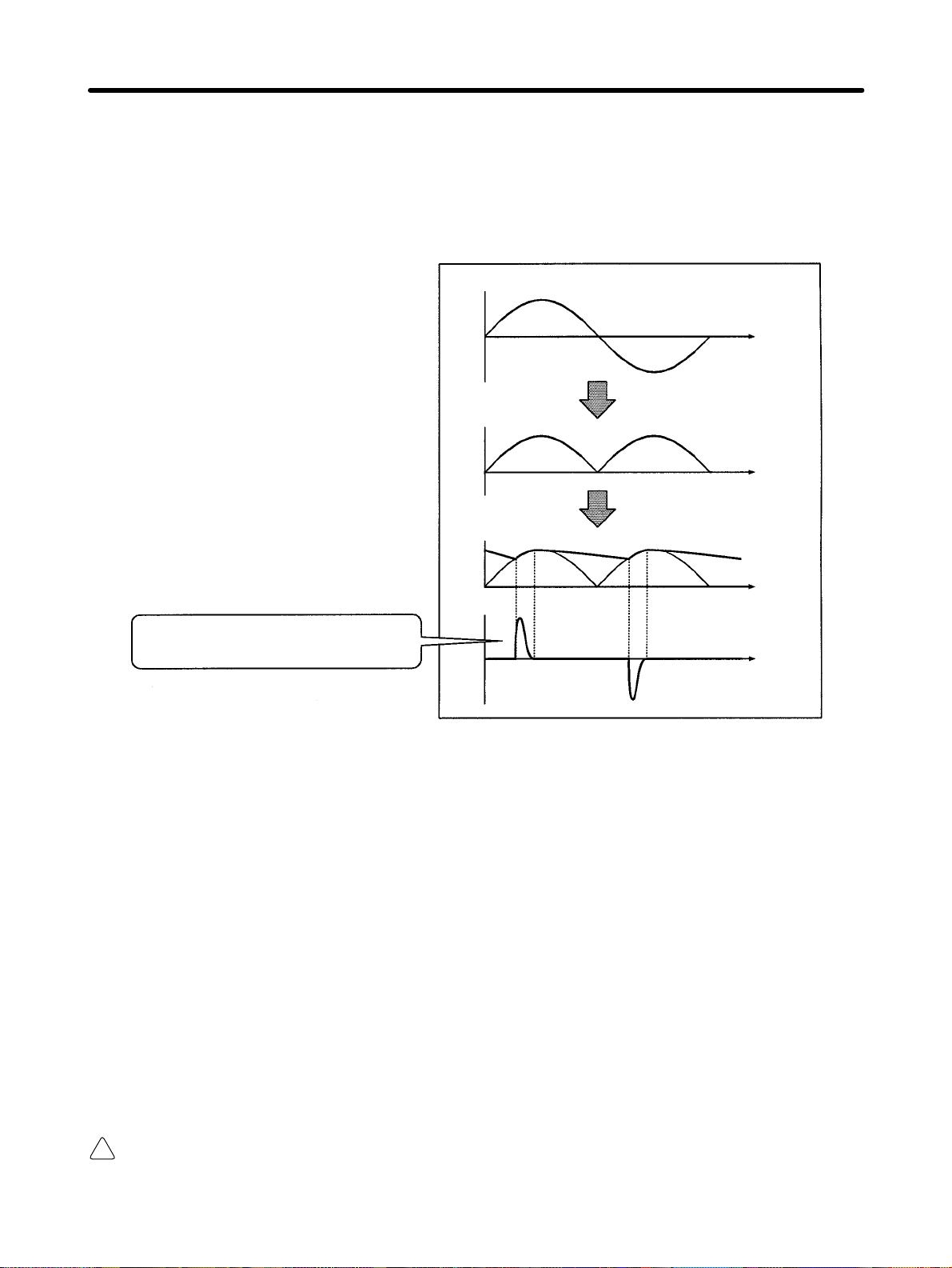
Installation Chapter 2
• Inverter
The Inverter as well as normal electric machines has an input current containing harmonics because
the Inverter converts AC into DC.
The output current of the Inverter is comparatively high. Therefore, the ratio of harmonics in the output
current of the Inverter is higher than that of any other electric machine.
Voltage
Time
Rectified
Voltage
Time
Smoothed
Voltage
Time
Current
A current flows into the capacitors. The
current is different from the voltage in
waveform.
Time
Countermeasures with Reactors against Harmonics Generation
• DC/AC Reactors
The DC reactor and AC reactor suppress harmonics and currents that change suddenly and greatly.
The DC reactor suppresses harmonics better than the AC reactor. The DC reactor used with the AC
reactor suppresses harmonics more effectively.
The input power factor of the Inverter is improved by suppressing the harmonics in the input current of
the Inverter.
Note 18.5- to 160-kW Inverters have a built-in DC reactor.
185- to 300-kW Inverters cannot use a DC reactor.
• Connection
Connect the DC reactor to the internal DC power supply of the Inverter after shutting off the power
supply to the Inverter and making sure that the charge indicator of the Inverter turns off.
WARNING Do not touch the internal circuitry of the Inverter in operation, otherwise an electric
!
shock or a burn injury may occur.
2-35
Page 71

pp
Installation Chapter 2
• Wiring Method
With DC Reactor
DC reactor
(optional)
200 VAC (400 V)
L1 (R)
L2 (S)
L3 (T)
3G3FV
Note Be sure to remove the short bar on terminals +1 and +2 before connecting the DC reactor.
With DC and AC Reactors
DC reactor
(optional)
T1 (U)
T2 (V)
T3 (W)
200 VAC (400 V)
AC reactor
(optional)
L1 (R)
L2 (S)
L3 (T)
3G3FV
T1 (U)
T2 (V)
T3 (W)
Note Be sure to remove the short bar on terminals +1 and +2 before connecting the DC reactor.
• Reactor Effects
Harmonics are effectively suppressed when the DC reactor is used with the AC reactor as shown in
the following table.
Harmonic suppres-
sion method
5th har-
monic
7th har-
monic
No reactor 65 41 8.5 7.7 4.3 3.1 2.6 1.8
AC reactor 38 14.5 7.4 3.4 3.2 1.9 1.7 1.3
DC reactor 30 13 8.4 5 4.7 3.2 3.0 2.2
DC and AC reactors 28 9.1 7.2 4.1 3.2 2.4 1.6 1.4
Harmonic generation rate (%)
11th
harmon-
ic
13th
harmon-
ic
17th
harmon-
ic
19th
harmon-
ic
23th
harmon-
ic
25th
har-
monic
2-36
Page 72

Installation Chapter 2
Connecting the Braking Resistor
• Connect the braking resistor as shown in the following diagram.
• When using a Braking Resistor Unit, set L8-01 to “1” (i.e., overheating protection of the braking resis-
tor) and set L3-04 to “0” (i.e., no decelerating stall prevention) or “2” (i.e., braking with stall prevention).
Inverter
Caution The braking resistor’s connection terminals are B1 and B2. Do not connect any other
!
terminals. Connecting any terminals other than B1 or B2 can cause the resistor to
overheat, resulting in damage to the equipment.
Braking resistor
Connecting the Braking Resistor Unit and Braking Unit
• Connect the Braking Resistor Unit and Braking Unit to the Inverter as shown in the following diagrams.
• Set L8-01 to “0” (i.e., no overheating protection of the braking resistor) and L3-04 to “0” (i.e., no decel-
erating stall prevention) or “2” (i.e., braking with stall prevention) before using the Inverter with the
Braking Resistor Unit connected.
Note 1. Set L8-01 to “1” before operating the Inverter with the braking resistor without thermal relay
trip contacts.
Note 2. The Braking Resistor Unit cannot be used and the deceleration time cannot be shortened by
the Inverter if L3-04 is set to “1” (i.e., decelerating stall prevention).
• To prevent the Unit from overheating, make a power supply sequence as shown below or connect the
thermal relay trip output of the Unit to the external fault input terminal of the Inverter to interrupt the
running of the Inverter.
200-V Class with 0.4- to 7.5-kW Output and 400-V Class with 0.4- to 15-kW Output
Braking Resistor Unit
Inverter
Thermal relay
trip contact
2-37
Page 73

Installation Chapter 2
200-V Class with 11-kW-or-more Output and 400-V Class with 18.5-or-more Output
Braking Unit
Inverter
N
Thermal relay trip contact
Braking Resistor Unit
Thermal relay
trip contact
Connecting Braking Units in Parallel
When connecting two or more Braking Units in parallel, use the wiring and connectors shown in the
following diagram. There are connectors for selecting whether each Braking Unit is to be a Master or
Slave. Select “Master” for the first Braking Unit only; select “Slave” for all other Braking Units (i.e., from
the second Unit onwards).
Thermal
relay trip
contact
Braking
Resistor
Unit
Thermal
relay trip
contact
Braking
Resistor
Unit
Thermal
relay trip
contact
Braking
Resistor
Unit
Inverter
Braking Unit #1
Thermal
relay trip
contact
Braking Unit #2
Thermal
relay trip
contact
Braking Unit #3
Thermal
relay trip
contact
2-38
Page 74

l
Installation Chapter 2
Power Supply Sequence
Power
200-V class: Three-phase, 200 to
400-V class: Three-phase, 380 to
230 VAC (50/60 Hz)
460 VAC (50/60 Hz)
supply
(See note)
Note Use a transformer with 200- and 400-V outputs for the power supply of the 400-V Inverter.
L1 (R)
L2 (S)
L3 (T)
Inverter
2-2-5 Wiring Control Circuit Terminals
A control signal line must be 50 m maximum and separated from power lines. The frequency reference must be input to the Inverter through twisted-pair wires.
Wire Size and Round Solderless Terminals
Use thick wires to prevent voltage drops if the wires are long.
Wires for All Inverter Models
Terminal Terminal
screw
1 to 11, 13 to 33 M3.5 Stranded wire: 0.5 to 1.25
12 (G) M3.5 0.5 to 2
Round Solderless Terminals for Ground Terminal
Wire thickness
(mm2)
0.5
0.75 1.25 to 3.5
1.25 1.25 to 3.5
2 2 to 3.5
Terminal
screw
M3.5
1.25 to 3.5
Wire thickness (mm2) Type
Single wire: 0.5 to 1.25
Size Screw torque
0.8
Shielded, twisted-pair wire
Shielded,
polyethylene-covered, viny
sheath cable
(N m)
Considerations When Wiring Control Circuit Terminals
• Wire control signal lines separately from the main circuit lines and other power lines.
• Wire control circuit terminals 9, 10, 18, 19, and 20 (contact outputs) separately from terminals 1 to 8,
21, 22, 23, 25, 26, 27, 33, and 11 to 17.
• Connect shielded wire to terminal 12(G).
• Insulate the shielded areas with tape to prevent contact with other signal lines and equipment.
2-39
Page 75

Installation Chapter 2 2-2-6 Installing and Wiring PG Speed Control Cards
PG Speed Control Cards are used for executing speed control using a pulse generator (PG). There are
four types of PG speed control, as shown below. Select the type that fits the application and control
method.
3G3FV-PPGA2: A-phase (single) pulse input for open collector output, special-purpose V/f control
3G3FV-PPGB2: A/B-phase pulse input for open collector output, special-purpose vector control
3G3FV-PPGD2: A-phase (single) pulse input, line driver input, special-purpose V/f control
3G3FV-PPGX2: A/B/Z-phase pulse input, line driver input, special-purpose vector control
Installing a PG Speed Control Card
1. Turn off the main-circuit power supply, and leave it off for at least one minute before removing the
front cover of the Inverter (or at least three minutes for Inverters of 30 kW or more). Check to be sure
that the CHARGE light is OFF.
2. Insert the spacer (which is provided) into the spacer hole in the Inverter’s mounting base. For Inverters of 3.7 kW or less, there are two adjacent holes. Insert the spacer into the 7CN hole. The spacer
cannot be easily removed if inserted into the wrong hole. Be very careful to insert the spacer into the
correct hole, and in the proper direction.
3. Referring to the e n l a r ged illustration in the following diagram, align the PG Speed Control Card with
the catch position as shown by (1) and (2) and fit it precisely to the Option-A connector. Then pass
the spacer through the spacer hole at the Card. (Refer to illustration A.) Check to be sure that it is
precisely aligned with the 4CN position, and snap it into the proper position.
Option A mounting spacer
PG Speed Control Card
4CN
Option-A
Connector
2CN
Option-C
Connector
3CN
Option-D
Connector
Spacer mounting hole
Control
board
Option C
PG Speed
Control Card
Option D
(Accessory: SRNT41028-9)
Inverter mounting base
Inverter mounting base
Mounting
base side
Spacer mounting
Spacer mounting hole
Spacer
Option A side
2-40
Front
Enlargement
Side
Page 76

pp y p g
t
l
i
p
pp y p g
pp
pp
pp y p g
p( p)
p( p)
Installation Chapter 2
PG Speed Control Card Terminal Blocks
3G3FV-PPGA2 (For V/f With PG Feedback Mode Only)
Terminal No. Contents Specifications
TA1
TA2 (E) Shielded-wire connection terminal ---
1
2
3
4
5
6 Pulse input common
7
8
3G3FV-PPGB2 (For Flux Vector Control Mode Only)
Power supply for pulse generator
+12-V/open collector switching
ermina
Pulse input terminal
Pulse motor output terminal
12 VDC (±5%), 200 mA max.
0 VDC (GND for power supply)
Terminal for switching between12-V voltage
nput and open collector input. For open
collector input, short across 3 and 4.
H: +4 to 12 V; L: +1 V max. (Maximum
response frequency: 30 kHz)
12 VDC (±10%), 20 mA max.
Pulse monitor output common
Terminal No. Contents Specifications
TA1
TA2
TA3 (E) Shielded-wire connection terminal ---
1
2
3
4 Pulse input common
5
6 Pulse input common
1
2
3
4
Power supply for pulse generator
A-phase pulse input terminal
B-phase pulse input terminal
A-phase monitor output terminal
B-phase monitor output terminal
12 VDC (±5%), 200 mA max.
0 VDC (GND for power supply)
H: +8 to 12 V; L: +1 V max. (Maximum
response frequency: 30 kHz)
H: +8 to 12 V; L: +1 V max. (Maximum
response frequency: 30 kHz)
Open collector output, 24 VDC, 30 mA max.
A-phase monitor output common
Open collector output, 24 VDC, 30 mA max.
B-phase monitor output common
3G3FV-PPGD2 (For V/f With PG Feedback Mode Only)
Terminal No. Contents Specifications
TA1
TA2 (E) Shielded-wire connection terminal ---
1
2
3 5 VDC (±5%), 200 mA max. (see note)
4 Pulse input + terminal
5 Pulse input – terminal
6 Common terminal --7 Pulse monitor output + terminal
8 Pulse monitor output – terminal
Power supply for pulse generator
12 VDC (±5%), 200 mA max. (see note)
0 VDC (GND for power supply)
Line driver input (RS-422 level input)
Maximum response frequency: 300 kHz
Line driver output (RS-422 level output)
Note 5 VDC and 12 VDC cannot be used at the same time.
2-41
Page 77

pp y p g
p( p)
p( p)
Installation Chapter 2
3G3FV-PPGX2 (For Flux Vector Control Mode Only)
Terminal No. Contents Specifications
TA1
TA2
TA3 (E) ---
1
2
3 5 VDC (±5%), 200 mA max. (see note)
4 A-phase + input terminal
5 A-phase – input terminal
6 B-phase + input terminal
7 B-phase – input terminal
8 Z-phase + input terminal
9 Z-phase – input terminal
10 Common terminal 0 VDC (GND for power supply)
1 A-phase + output terminal
2 A-phase – output terminal
3 B-phase + output terminal
4 B-phase – output terminal
5 Z-phase + output terminal
6 Z-phase – output terminal
7 Control circuit common Control circuit GND
Power supply for pulse generator
12 VDC (±5%), 200 mA max. (see note)
0 VDC (GND for power supply)
Line driver input (RS-422 level input)
Maximum response frequency: 300 kHz
Line driver output (RS-422 level output)
Note 5 VDC and 12 VDC cannot be used at the same time.
2-42
Page 78

Installation Chapter 2
Wiring a PG Speed Control Card
3G3FV-PPGA2 (For V/f With PG Feedback Mode Only)
Three-phase,
200 VAC (400 VAC)
Three-phase,
200 VAC (400 VAC)
3G3FV
L1
L2
L3
3G3FV
L1
L2
L3
T1
T2
T3
T1
T2
T3
E6B2-CWZ3E Encoder
+12-V power supply
0-V power supply
12-V voltage output
(A/B phase)
Pulse 0 V
Pulse monitor output
E6B2-CWZ3C Encoder
+12-V power supply
0-V power supply
Open collector output
(A/B phase)
Pulse 0 V
Pulse monitor output
Note 1. Twisted-pair shielded wire must be used for signal lines.
Note 2. Do not use the pulse generator’s power supply for anything other than the pulse generator
(encoder). Using it for another purpose can cause malfunctions due to noise.
Note 3. The length of the pulse generator’s wiring must not be more than 30 meters.
2-43
Page 79

Installation Chapter 2
I/O Circuit Configuration
PG power
supply +12 V
Pulse input
1 K
3 K
+12 V
0 V
2 K 2 K
+12 V
+12 V
0 V
3.9 K
Pulse input
1 K
+12 V
Pulse
monitor
output
0 V
0 V
Note When connecting to a voltage-output-type PG (encoder), select a PG with an output impedance
of no more than 3 kΩ.
3G3FV-PPGB2 (For Flux Vector Control Mode Only)
Three-phase 200 VAC
(400 VAC)
L1
L2
L3
T1
T2
T3
3G3FV-PPGB2
Power supply +12 V
Power supply 0 V
Power supply +12 V
A-phase pulse output
Power supply +12 V
B-phase pulse output
Encoder
A-phase pulse
monitor output
B-phase pulse
monitor output
Note 1. Twisted-pair shielded wire must be used for signal lines.
Note 2. Do not use the pulse generator’s power supply for anything other than the pulse generator
(encoder). Using it for another purpose can cause malfunctions due to noise.
Note 3. The length of the pulse generator’s wiring must not be more than 30 meters.
2-44
Page 80

Installation Chapter 2
I/O Circuit Configuration
PG power
supply +12 V
A-phase
pulse input
B-phase
pulse input
+12 V
0 V
Division rate circuit
A-phase
pulses
B-phase
pulses
A-phase pulse
monitor output
B-phase pulse
monitor output
Forward output pulses
A-phase pulses
B-phase pulses
Note When connecting to a voltage-output-type PG (encoder), select a PG that has an output imped-
ance with a c u r r e n t o f at least 12 mA to the input circuit photocoupler (diode). The E6B2-CWZ3E
cannot be used.
3G3FV-PPGD2 (For V/f With PG Feedback Mode Only)
Three-phase
200 VAC (400 VAC)
L1
L2
L3
T1
T2
T3
3G3FV-PPGD2
Power supply 0 V
Power supply 5 V
Pulse output + (A/B phase)
Pulse output –
(A/B phase)
Encoder
Pulse monitor output
Note 1. Twisted-pair shielded wire must be used for signal lines.
Note 2. Do not use the pulse generator’s power supply for anything other than the pulse generator
(encoder). Using it for another purpose can cause malfunctions due to noise.
Note 3. The length of the pulse generator’s wiring must not be more than 50 meters.
2-45
Page 81

Installation Chapter 2
3G3FV-PPGX2 (For Flux Vector Control Mode Only)
Three-phase
200 VAC (400 VAC)
L1
L2
L3
Encoder
T1
T2
T3
3G3FV-PPGX2
Power supply 0 V
Power supply 5 V
A-phase pulse output +
A-phase pulse output –
B-phase pulse output +
B-phase pulse output –
Z-phase pulse output +
Z-phase pulse output –
A-phase pulse monitor
output
B-phase pulse monitor
output
Z-phase pulse monitor
output
Note 1. Shielded, twisted-pair wire must be used for signal lines.
Note 2. Do not use the pulse generator’s power supply for anything other than the pulse generator
(encoder). Using it for another purpose can cause malfunctions due to noise.
Note 3. The length of the pulse generator’s wiring must not be more than 50 meters.
Wiring PG Speed Control Card Terminal Blocks
Use no more than 30 meters of wiring for PG (encoder) signal lines and no more than 50 meters for
3G3FV-PPGD2 and 3G3FV-PPGX2, and keep them separate from power lines. Use shielded, twistedpair wire fo r pulse i nput and pulse output monitor wire, and connect the shield to the shielded wire connection terminal.
Wires for All Inverter Models
Terminal Terminal
Pulse generator power supply
Pulse input terminal
Pulse monitor output terminal
Shielded wire connection
terminal
screw
--- Stranded wire: 0.5 to 1.25
M3.5 0.5 to 2
Wire thickness (mm2) Type
Shielded, twisted-pair wire
Single wire: 0.5 to 1.25
Shielded, polyethylene-covered, vinyl sheath cable
2-46
Page 82

Installation Chapter 2
Solderless Terminals for Control Circuit Terminals
The use of solderless terminals for the control circuit terminals is recommended because solderless
terminals are easy to connect securely.
d1 dia.
d2 dia.
Wire thickness Model d1 d2 Manufacturer
0.5 mm
0.75 mm
2
1 mm
1.5 mm
2
2
2
A1 0.5-8WH 1.00 2.60
A1 0.75-8GY 1.20 2.80
A1 1-8RD 1.40 3.00
A1 1.5-8BK 1.70 3.50
Phoenix Contact
Note Do not solder wires with the control circuit terminals if wires are used instead of solderless termi-
nals. Wires may not contact well with the control circuit terminals or the wires may be disconnected from the control circuit terminals due to vibration if the wires are soldered.
Round Solderless Terminal Sizes and Screw Torque
Wire thickness (mm2) Terminal screw Size
0.5
0.75 1.25 to 3.5
1.25 1.25 to 3.5
2 2 to 3.5
M3.5
1.25 to 3.5
Screw torque (N m)
0.8
Wiring Control Circuit Terminals
Wiring Method
1. Loosen the terminal screws with a thin-slotted screwdriver.
2. Insert the wires from underneath the terminal block.
3. Tighten the terminal screws firmly.
Note 1. Always separate the control signal line from the main circuit cables and other power cables.
Note 2. Do not solder the wires to the control circuit terminals. The wires may not contact well with the
control circuit terminals if the wires are soldered.
Note 3. The end of each wire connected to the control circuit terminals must be stripped for approxi-
mately 7 mm.
Note 4. Use a shielded wire for the ground terminal.
2-47
Page 83

Installation Chapter 2
Note 5. Insulate the shield with tape so that the shield will not touch any signal line or device.
Strip the end for 7 mm if
no solderless terminal is
used.
Thin-slotted screwdriver
Control circuit
terminal block
Solderless terminal or
wire without soldering
Wires
Blade of screwdriver
3.5 mm max.
Blade thickness: 0.6 mm max.
Note 6. Tighten the screws to a tightening torque of 0.5 to 0.6 Nm. The terminal block may be dam-
aged if the tightening torque is too strong, and malfunctions and short-circuits may result if the
tightening torque is too weak.
Selecting the Number of PG (Encoder) Pulses
3G3FV-PPGA2/-PPGB2
• The maximum response frequency is 30 kHz.
• Taking into consideration the encoder pulse deviation (phase difference: 90 ±45°) and the waveform
when the cable is long, select a smaller number of pulses than the ones shown in the following table.
Motor’s maximum speed (r/min) 1,800 1,500 900
Number of encoder pulses (p/r) 500 600 1,00
Maximum encoder frequency (kHz) 15 15 15
3G3FV-PPGD2/-PPGX2
• The maximum response frequency is 300 kHz.
• When the encoder pulse deviation (phase difference: 90 ±45°) is taken into consideration, the number
of encoder pulses can be calculated by means of the following formula:
60 x maximum response frequency (300,000 Hz)
Number of encoder pulses [p/r]
• If the motor’s maximum speed is less than 4,000 r/min, an encoder of 1,000 to 2,000 p/r is recommended. Even if an encoder with higher than required resolution is selected, it will not improve the
speed control range or precision.
x
2 x motor’s maximum rotation speed (r/min)
2-48
Page 84

3
Chapter 3
Preparing for Operation
3-1 Using the Digital Operator
3-2 Modes
3-3 Operation Mode
3-4 Initialize Mode
3-5 Program Mode
3-6 Auto-tuning Mode
3-7 Modified Constants Mode
3-8 Operation Mode Selection Key and
Local/Remote Selection Input
Page 85

Preparing for Operation Chapter 3 3-1 Using the Digital Operator
Operation Mode Indicators
DRIVE: Lit when in operation mode.
FWD: Lit when there is a forward command input.
REV: Lit when there is a reverse command input.
SEQ: Lit when the forward/reverse command from
REF: Lit when the frequency reference from
Two-line LCD that displays data for monitoring, parameter names, and set values with 16 characters
per line.
Execute operations such as setting parameters,
monitoring, JOG, and auto-tuning.
the control circuit terminal is enabled.
control circuit terminals 13 and 14 is enabled.
Data Display
Keys
Key Name Function
Operation Mode
Selection Key
Switches between Operator and parameter setting (run command and
frequency reference). This key can be enabled or disabled with a
parameter setting (o2-02).
Menu Key Displays each mode.
Escape Key Returns to the status before the Enter Key is pressed.
Jog Key Enables JOG operation when the 3G3FV is in operation with the
Digital Operator.
Forward/Reverse
Rotation Selection Key
Reset/Digit Selection
Key
Selects the rotation direction of the motor when the 3G3FV is in
operation with the Digital Operator.
Selects digits for parameter settings. Also acts as the reset key when
an fault has occurred. (See note.)
Increment Key Selects modes, groups, functions, parameter names, and set values.
This key increases numbers when pressed.
Decrement Key Selects modes, groups, functions, parameter names, and set values.
This key decreases numbers when pressed.
Enter Key Enters modes, functions, constants, and set values after they are set.
Run Key Starts the 3G3FV running when the 3G3FV is in operation with the
Digital Operator.
Stop Key Stops the 3G3FV running. This key can be enabled or disabled with a
parameter setting (o2-02) in operation with the control circuit terminal.
Note For safety reasons, the Reset Key cannot be used when a run command (forward/reverse) is be-
ing input. Turn OFF the run command before attempting to reset.
3-2
Page 86

Preparing for Operation Chapter 3 3-2 Modes
This section describes the 3G3FV’s various parameter setting and monitoring modes.
Inverter Modes
• The SYSDRIVE 3G3FV Inverter’s parameters and monitoring functions have been organized in
groups, so it is easier to make settings and read data. These function groups are known as modes.
• The 3G3FV is equipped with 5 modes, as shown in the following table.
Mode Primary function(s)
Operation mode The Inverter can be run in this mode.
Use this mode when monitoring values such as frequency references or output
current, displaying fault information, or displaying the fault history.
Initialize mode Use this mode when selecting the language displayed on the Digital Operator,
selecting the access level for setting/reading parameters, selecting the control mode,
or initializing the parameters.
Program mode Use this mode when setting/reading the parameters required for operation. The
program-mode functions are subdivided into the following groups:
Application: Operation mode selection, DC control, speed search, etc.
Tuning: Acceleration/deceleration times, S-curve characteristics, carrier
frequencies, etc.
Reference: Settings related to frequency control
Motor: V/f characteristics and motor parameters
Option: Settings for Optional Cards
Terminal: Settings for sequential I/O and analog I/O
Protection: Settings for the motor and inverter protection functions
Operator: Selects the Digital Operator’s display and key functions
Auto-tuning
mode
Modified
constants mode
(Usable only with the vector control mode)
Use this mode when running a motor with unknown motor parameters in the vector
control mode. The motor parameters are calculated and set automatically.
Use this mode to set/read parameters that have been changed from their factory-set
values.
Switching Modes
• Once the Unit has been put into operation mode by pressing the Menu Key, the Increment and Decrement Keys can be pressed to switch to other modes.
• Press the Enter Key to set/read the parameters in each mode.
3-3
Page 87

Preparing for Operation Chapter 3
• Press the Escape Key to return to the mode display from the parameter display.
All modes/parameters status
• Operation mode
** Main Menu **
Operation
• Initialize mode
** Main Menu **
Initialize
• Programming mode
** Main Menu **
Programming
Power ON
Monitor (Frequency reference value)
Frequency Ref
U1Ć01= 60.00 HZ
Operator display language selection
Select Language
English
Frequency reference input method
selection (see note 2)
Reference Source
Operator
• Auto-tuning mode (see note 1)
** Main Menu **
AutoĆTuning
Auto-tuning (Rated voltage setting)
Rated Voltage
200.0 VAC
Display parameters changed from
• Modified constants mode
** Main Menu **
Modified Consts
factory settings
Reference 1
d1Ć01= 60.00 HZ
Note 1. Auto-tuning mode will be displayed only when vector control mode has been selected. (The
factory setting is for open-loop vector control.)
Note 2. The actual display depends on the parameter access level setting (A1-01).
3-4
Page 88

Preparing for Operation Chapter 3
Parameter Access Level
The SYSDRIVE 3G3FV’s has three access levels which divide the various parameters based on their
usage, as shown below. The access level restricts which parameters can be set or displayed.
Level Function
Quick-start Allows setting/reading of parameters required for test runs. (factory-set)
Basic Allows setting/reading of general-purpose parameters.
Advanced Allows setting/reading of all parameters.
Set the access level in initialize mode with parameter A1-01.
Changing the Access Level from Quick-start to Basic
Key sequence Display Explanation
** Main Menu **
Operation
** Main Menu **
Initialize
Select Language
English
Access Level
Quick Start
A1Ć01= 2 ***
Quick Start
A1Ć01= 3
Basic Level
Entry Accepted
Access Level
Basic Level
Displays operation mode.
Displays initialize mode.
Puts the Unit in initialize mode.
Switches to the access level parameter.
Displays the access level parameter setting.
Changes the access level setting to “BASIC.”
Writes the new parameter setting.
Returns to the access level parameter display.
3-5
Page 89

Preparing for Operation Chapter 3
The following diagram shows this procedure in flowchart format.
** Main Menu **
Operation
** Main Menu **
Initialize
Select Language
English
Access Level
Quick Start
Access Level
Basic Level
A1Ć01= 2 ***
QuickĆStart
A1Ć01= 3
Basic Level
Entry Accepted
Setting Parameters in Each Access Level
• The displays in program mode differ for each access level. (There is no difference in other modes.)
• This section provides the procedure to change the acceleration time to 20 s in each access level. The
acceleration time (C1-01) is a parameter in program mode.
• If the new parameter setting is not written to the Unit (by pressing the Enter Key) within one minute
after starting the procedure, the display will automatically revert to the original parameter setting. In
this case, the procedure must be started again.
3-6
Page 90

Preparing for Operation Chapter 3
Parameter Setting Levels (Partial)
MENU
Operation mode
Initialize mode
Program mode
[Mode] [Group] [Function] [Parameter]
Application b1 Sequence b1-01 Reference source
b1-02 Run source
Tuning
Reference
Parameter to be changed
C2 S-Curve Acc/Dec
b1-03 Stopping method
C1-01 Accel Time 1C1 Accel/Decel
C1-02 Decel Time 1
Setting the Parameter in the Quick-start Access Level
The parameter level will be displayed when the Enter Key is pressed at the program mode display.
Key sequence Display Explanation
** Main Menu **
Displays operation mode.
Operation
2 times
** Main Menu **
Programming
Reference Source
Terminals
Run Source
Displays program mode.
Puts the Unit in program mode.
Displays the b1-01 Reference source selection.
Displays the b1-02 Run source selection.
Terminals
Stopping Method
Displays the b1-03 Stopping method selection.
Ramp to Stop
Accel Time 1
Displays C1-01 Acceleration time 1.
c1Ć01= 10.0 Sec
Selects the parameter so that the leading 0 flashes.
(The digit that can be changed flashes.)
Moves the cursor so that the “1” digit flashes.
Changes the 1 to a 2.
2 times
Accel Time 1
0010.0 Sec
Accel Time 1
0010.0 Sec
Accel Time 1
0020.0 Sec
Writes the new setting.
Entry Accepted
---
Accel Time 1
Returns to the C1-01 Acceleration time 1 display.
c1Ć01= 20.0 Sec
** Main Menu **
Returns to the program mode display.
Programming
3-7
Page 91

Preparing for Operation Chapter 3
Setting the Parameter in the Basic Access Level
The function level will be displayed when the Enter Key is pressed at the program mode display.
Key sequence Display Explanation
Displays operation mode.
Displays program mode.
Puts the Unit in program mode.
Displays the b1 Sequence function selection.
Displays the b2 DC Braking function selection.
Displays the C1 Accel/Decel function selection.
Displays C1-01 Acceleration time 1.
Selects the parameter so that the leading 0 flashes.
(The digit that can be changed flashes.)
Moves the cursor so that the “1” digit flashes.
Changes the 1 to a 2.
Writes the new setting.
Returns to the C1-01 Acceleration time 1 display.
Returns to the program mode display.
---
2 times
2 times
** Main Menu **
Operation
** Main Menu **
Programming
Function b1
Sequence
Function b2
DC Braking
Function C1
Accel/Decel
Accel Time 1
c1Ć01= 10.0 Sec
Accel Time 1
0010.0 Sec
Accel Time 1
0010.0 Sec
Accel Time 1
0020.0 Sec
Entry Accepted
Accel Time 1
c1Ć01= 20.0 Sec
Function C1
Accel/Decel
3-8
Page 92

Preparing for Operation Chapter 3
Setting the Parameter in the Advanced Access Level
The group level will be displayed when the Enter Key is pressed at the program mode display.
Key sequence Display Explanation
Displays operation mode.
Displays program mode.
Puts the Unit in program mode.
Displays the Group b Application group selection.
Displays the Group C Tuning group selection.
Displays the C1 Accel/Decel function selection.
Displays C1-01 Acceleration time 1.
Selects the parameter so that the leading 0 flashes.
(The digit that can be changed flashes.)
Moves the cursor so that the “1” digit flashes.
Changes the 1 to a 2.
Writes the new setting.
Returns to the C1-01 Acceleration time 1 display.
Returns to the C1 Accel/Decel function selection.
---
2 times
2 times
** Main Menu **
Operation
** Main Menu **
Programming
Group b
Application
Group C
Tuning
Function C1
Accel/Decel
Accel Time 1
c1Ć01= 10.0 Sec
Accel Time 1
0010.0 Sec
Accel Time 1
0010.0 Sec
Accel Time 1
0020.0 Sec
Entry Accepted
Accel Time 1
c1Ć01= 20.0 Sec
Function C1
Accel/Decel
3-9
Page 93

Preparing for Operation Chapter 3 3-3 Operation Mode
Operation mode is the mode in which the Inverter can run. When running the Inverter,
press the Enter Key from the operation mode display to bring up the monitor display. Run
commands can’t be received from any other display. O nce the Unit is running, it can be
switched to other modes.
Many parameters can’t be changed when the Inverter is running. Refer to Chapter 7
Parameter Lists for details.
Bring up monitor displays such as the frequency reference, output frequency, output
current, and output voltage as well as fault information and the fault history in operation
mode.
3-10
Page 94

Preparing for Operation Chapter 3
Operations in Operation Mode
All modes/parameters status
Operation mode Frequency reference setting/display
** Main Menu **
Operation
Frequency Ref
U1Ć01= 0.00 HZ
Output frequency display
Output Freq
U1Ć02= 0.00 HZ
Output current display
Output Current
U1Ć03= 0.00 A
Output voltage display
Output Voltage
U1Ć06= 0.0 VAC
Power ON
Function selection U2 (fault trace)
Function U2
Fault Trace
Function selection U3
(fault history)
Function U3
Fault History
Function selection U1 (Monitor)
Function U1
Monitor
Contents of fault trace
Contents of fault history
Various monitors
3-11
Page 95

py
pg
Preparing for Operation Chapter 3
Conditions for Monitoring
The following tables show the items that can be monitored in operation mode. The table’s “Valid access
levels” column indicates whether an item can be monitored in a particular access level and control
mode. The codes in this column have the following meanings.
Q: These items can be monitored in all access levels. (Quick-start, Basic, and Advanced)
B: These items can be monitored in the Basic and Advanced access levels.
A: These items can be monitored in the Advanced access level only.
X: These items cannot be monitored in the control mode shown.
The output signal levels for multi-function analog outputs shown in the table are for a gain of 100.0 and a
bias of 0.00.
Status Monitor
Item Display Function Output signal
U1-01 Frequency Ref Monitors/sets the frequency reference
U1-02 Output Freq Monitors the output frequency.
U1-03 Output Current Monitors the output current. 10 V: Rated current
U1-04 Control Method Shows which control mode is set. Can’t be output. --- Q Q Q Q
U1-05 Motor Speed Monitors the motor speed. 10 V:
U1-06 Output Voltage Monitors the Inverter ’s internal output
U1-07 DC Bus Voltage Monitors the DC voltage of the Inverter’s
U1-08 Output kWatts Monitors the output power. (This is an in-
U1-09 Torque Reference Monitors the internal torque reference
U1-10 Input Term Sts
(Input terminal
status)
value.
The display units can be set with param-
eter o1-01.
The display units can be set with parameter o1-01.
voltage reference value.
internal main circuit.
ternally detected value.)
value when vector control is used.
Shows the ON/OFF status of inputs.
U1-10=00000000
1: Terminal 1 ON
1: Terminal 2 ON
1: Terminal 3 ON
1: Terminal 4 ON
1: Terminal 5 ON
1: Terminal 6 ON
1: Terminal 7 ON
1: Terminal 8 ON
levels for
multi-function
analog outputs
10 V:
Max. frequency
(0 to ±10 V possible)
10 V:
Max. frequency
(0 to ±10 V possible)
(0 to +10 V output)
Max. frequency
(0 to ±10 V possible)
10 V: 200 (400) VAC
(0 to +10 V output)
10 V: 400 (800) VDC
(0 to +10 V output)
10 V:
Max. motor capacity
(0 to ±10 V possible)
10 V: Rated torque
(0 to ±10 V possible)
Can’t be output. --- Q Q Q Q
Min.
Units
0.01HzQ Q Q Q
0.01HzQ Q Q Q
0.1 A Q Q Q Q
0.01HzX Q Q Q
0.1 V Q Q Q Q
1 V Q Q Q Q
0.1kWQ Q Q Q
0.1% X X Q Q
Valid access levels
V/f V/f
w/PG
Open
Vec-
tor
Flux
Vec-
tor
3-12
Page 96

Preparing for Operation Chapter 3
Item Valid access levelsMin.
U1-11 Output Term Sts
(Output terminal
status)
U1-12 Int Ctl Sts 1
(Internal control
status)
U1-13 Elapsed Time Monitors the Inverter’s elapsed operating
U1-14 FLASH ID Manufacturer’s ID number Can’t be output. --- Q Q Q Q
U1-15 Term 13 Level
(Terminal 13 input
voltage level)
U1-16 Term 14 Level
(Terminal 14 input
current level)
U1-17 Term 16 Level
(Terminal 16 input
voltage level)
U1-18 Mot SEC Current Monitors the calculated value of the mo-
U1-19 Mot EXC Current Monitors the calculated value of the mo-
U1-20 SFS Output Monitors the output frequency after a soft
U1-21 ASR Input Monitors the input to the speed control
U1-22 ASR Output Monitors the output from the speed con-
U1-23 Speed Deviation Monitors the speed deviation within the
U1-24 PID Feedback Monitors the feedback value when PID
Shows the ON/OFF status of outputs.
U1-11=00000000
Shows the Inverter’s operating status.
U1-12=00000000
time.
The initial value and running/power-on
time selection can be set with parameters
o2-07 and o2-08.
Monitors the input voltage of the frequency reference (voltage).
An input of 10 V corresponds to 100%.
Monitors the input current of the frequen-
cy reference (current).
An input of 20 mA corresponds to 100%.
Monitors the input voltage of the multi-
function analog input.
An input of 10 V corresponds to 100%.
tor’s secondary current (Iq). The motor’s
rated current corresponds to 100%.
tor’s excitation current (Id). The motor’s
rated current corresponds to 100%.
start. The display shows the frequency
without the correction from compensation
functions such as slip compensation.
loop. The max. frequency corresponds to
100%.
trol loop. The motor’s rated current corresponds to 100%.
speed control loop. The max. frequency
corresponds to 100%.
control is used. The input for the max.
frequency corresponds to 100%.
FunctionDisplayItem
FunctionDisplay
1: Terminals 9–10 ON
1: Terminal 25 ON
1: Terminal 26 ON
Not used. (always 0)
1: Terminals 18/19–20
ON
1: Running
1: Zero-speed level
1: Reverse
1: Reset input ON
1: F.ref/F.out agree
1: Inverter ready
1: Minor fault detected
1: Major fault detected
Output signal
Output signal
levels for
levels for
multi-function
multi-function
analog outputs
analog outputs
Can’t be output. --- Q Q Q Q
Can’t be output. --- Q Q Q Q
Can’t be output. 1 hr Q Q Q Q
10 V: 100% (10 V)
(0 to ±10 V possible)
10 V: 100% (20 mA)
(0 to +10 V output)
10 V: 100% (10 V)
(0 to ±10 V possible)
10 V: Rated current
(0 to +10 V output)
10 V: Rated current
(0 to +10 V output)
10 V:
Max. frequency
(0 to ±10 V possible)
10 V:
Max. frequency
(0 to ±10 V possible)
10 V: Rated current
(0 to ±10 V possible)
10 V:
Max. frequency
(0 to ±10 V possible)
10 V:
Max. frequency
(0 to ±10 V possible)
Min.
Units
Units
0.1% B B B B
0.1% B B B B
0.1% B B B B
0.1% B B B B
0.1% X X B B
0.01HzA A A A
0.01%X A X A
0.01%X A X A
0.01%X A X A
0.01%A A A A
V/f
V/f
w/PG
Open
Vec-
tor
Flux
Vec-
tor
3-13
Page 97

Preparing for Operation Chapter 3
Item Valid access levelsMin.
U1-25 DI-16 Reference Monitors the reference value from a
3G3FV-PDI16H2 Digital Command Card.
The value will be displayed in binary or
BCD depending on parameter F3-01.
U1-26 Voltage Ref (Vq) Monitors the Inverter’s internal voltage
reference value for the motor’s secondary current control.
U1-27 Voltage Ref (Vd) Monitors the Inverter’s internal voltage
reference value for the motor’s excitation
current control.
U1-28 CPU ID Manufacturer’s CPU software ID number Can’t be output. 0.1 V A A A A
U1-32 ACR(q) Output Monitor ’s the current control output value
for the motor’s secondary current.
U1-33 ACR(d) Output Monitor ’s the current control output value
for the motor’s excitation current.
U1-34 OPE Detected Displays the first constant number for
which an OPE error was detected.
U1-35 Zero Servo Pulse Multiplies the number of PG pulses by
four to display the movement width at the
zero servo stop point.
U1-36 PID Input PID reference + PID reference bias – PID
feedback value
The max. frequency corresponds to
100%.
U1-37 PID Output PID control output
The max. frequency corresponds to
100%.
U1-38 PID Setpoint PID reference + PID reference bias
The max. frequency corresponds to
100%.
FunctionDisplayItem
FunctionDisplay
Output signal
Output signal
levels for
levels for
multi-function
multi-function
analog outputs
analog outputs
Can’t be output. --- A A A A
10 V: 200 (400) VAC
(0 to ±10 V possible)
10 V: 200 (400) VAC
(0 to ±10 V possible)
10 V: 100% 0.1% X X A A
10 V: 100% 0.1% X X A A
Can’t be output. --- A A A A
Can’t be output. 1 X X X A
10 V:
Max. frequency
10 V:
Max. frequency
10 V:
Max. frequency
Min.
Units
Units
0.1 V X X A A
0.1 V X X A A
0.01%A A A A
0.01%A A A A
0.01%A A A A
V/f
V/f
w/PG
Open
Vec-
tor
Flux
Vec-
tor
3-14
Page 98

py
pg
p
py
pg
p
Preparing for Operation Chapter 3
Fault Trace
Item Display Function Output signal
U2-01 Current Fault Information on the current fault
U2-02 Last Fault Information on the last fault
U2-03 Frequency Ref Frequency reference value when the “last
fault” occurred.
U2-04 Output Freq Output frequency when the “last fault” oc-
curred.
U2-05 Output Current Output current when the “last fault” occurred. 0.1 A Q Q Q Q
U2-06 Motor Speed Motor speed when the “last fault” occurred. 0.01HzX Q Q Q
U2-07 Output Voltage Output voltage when the “last fault” occurred. 0.1 V Q Q Q Q
U2-08 DC Bus Voltage The main circuit DC voltage when the “last
fault” occurred.
U2-09 Output kWatts Output power when the “last fault” occurred. 0.1kWQ Q Q Q
U2-10 Torque Reference Torque reference when the “last fault” oc-
curred. (The rated torque = 100%.)
U2-11 Input Term Sts Input terminal status when the “last fault” oc-
curred. (Same format as U1-10.)
U2-12 Output Term Sts Output terminal status when the “last fault”
occurred. (Same format as U1-11.)
U2-13 Inverter status Inverter operating status when the “last fault”
occurred. (Same format as U1-12.)
U2-14 Elapsed time Elapsed operating or power-on time when the
“last fault” occurred.
levels for
multi-function
analog outputs
Can’t be output.
Min.
Units
--- Q Q Q Q
--- Q Q Q Q
0.01HzQ Q Q Q
0.01HzQ Q Q Q
1 V Q Q Q Q
0.1% X X Q Q
--- Q Q Q Q
--- Q Q Q Q
--- Q Q Q Q
1 hr Q Q Q Q
Valid access levels
V/f V/f
w/PG
Open
Vec-
tor
Flux
Vec-
tor
Fault History
Item Display Function Output signal
U3-01 Last Fault Information on the last fault.
U3-02 Fault Message 2 Information on the 2nd to last fault.
U3-03 Fault Message 3 Information on the 3rd to last fault. --- Q Q Q Q
U3-04 Fault Message 4 Information on the 4th to last fault. --- Q Q Q Q
U3-05 Elapsed Time 1 Elapsed running or power-on time when the
last fault occurred.
U3-06 Elapsed Time 2 Elapsed running or power-on time when the
2nd to last fault occurred.
U3-07 Elapsed Time 3 Elapsed running or power-on time when the
3rd to last fault occurred.
U3-08 Elapsed Time 4 Elapsed running or power-on time when the
4th to last fault occurred.
levels for
multi-function
analog outputs
Can’t be output.
Min.
Units
--- Q Q Q Q
--- Q Q Q Q
1 hr Q Q Q Q
1 hr Q Q Q Q
1 hr Q Q Q Q
1 hr Q Q Q Q
Valid access levels
V/f V/f
w/PG
Open
Vec-
tor
Flux
Vec-
tor
3-15
Page 99

py
g
Preparing for Operation Chapter 3
Monitoring at Startup
• In operation mode, the frequency reference, output frequency, output current, and output voltage can
be monitored immediately if the default settings are being used. One of these four values, the output
voltage, can be changed to a different value. When a value other than the output voltage is to be monitored, set that value’s number in parameter o1-01 (user monitor selection).
• When the power is turned on, the frequency reference will appear in the Unit’s data display if the default settings are being used. Any one of the four values monitored at startup (frequency reference,
output frequency , output current, or the value set in parameter o1-01) can be selected to appear when
the power is turned on. The value that appears at startup is determined by parameter o1-02 (PowerOn Monitor).
• Parameters o1-01 and o1-02 can be changed in the Basic or Advanced access levels. These parameters can be changed during operation.
User Monitor Selection (Parameter o1-01)
Use parameter o1-01 to select the values that will be monitored at startup.
Use the last two digits from the “U1 Monitor” list (U1-) to select a value. For example, the torque
reference is U1-09, so input 9 to select the torque reference.
Parameter Display name Setting Units Default
number
o1-01 User Monitor Sel 4 to 28 --- 6 Basic or Advanced
range setting
V/f
Control
Valid access levels
V/f withPGOpen Loop
Vector
Flux
Vector
The following example shows how to change parameter o1-01 so that the output power is monitored at
startup instead of the output voltage.
Key sequence Display Explanation
Displays operation mode.
Displays program mode.
Puts the Unit in program mode.
Displays function selection o1.
Puts the Unit in function selection o1. (Monitor Select)
Displays the parameter setting for o1-01.
Sets the parameter to output power .
Writes the new setting.
Returns to the Monitor Select display.
2 times
2 times
** Main Menu **
Operation
** Main Menu **
Programming
Function b1
Sequence
Function o1
Monitor Select
User Monitor Sel
Output Voltage
o1Ć01= 6 ***
Output Voltage
o1Ć01= 8 ***
Output kWatts
Entry Accepted
User Monitor Sel
Output kWatts
Note In this example, the setting is changed in the Basic access level.
Power-On Monitor (Parameter o1-02)
Use parameter o1-02 to indicate which value will be displayed when the Unit is started.
A setting of 1 indicates the frequency reference, 2 indicates the output frequency , 3 indicates the output
current, and 4 indicates the value set in parameter o1-01.
3-16
Page 100

py
g
Preparing for Operation Chapter 3
Parameter Display name Setting Units Default
number
o1-02 Power-On
Monitor
range setting
1 to 4 --- 1 Basic or Advanced
V/f
Control
Valid access levels
V/f withPGOpen Loop
Vector
Flux
Vector
The following example shows how to change parameter o1-02 so that the output current is displayed at
startup. (The procedure continues from the end of the previous example.)
Key sequence Display Explanation
Monitor Select display (See the previous example.)
Displays the Power-On Monitor display.
Displays the parameter setting for o1-02.
Sets the parameter to output current.
Writes the new setting.
Returns to the Power-On Monitor display.
Returns to the function selection o1 display.
Returns to the program mode display.
2 times
User Monitor Sel
Output kWatts
PowerĆOn Monitor
Frequency Ref
o1Ć02= 1 ***
Frequency Ref
O1Ć02= 3
Output Current
Entry Accepted
PowerĆOn Monitor
Output Current
Function o1
Monitor Select
** Main Menu **
Programming
Note In this example, the setting is changed in the Basic access level.
3-17
 Loading...