

Omron 3G3EV-A2001-CUE, 3G3EV-A2007-CUE, 3G3EV-A2002-CUE, 3G3EV-A2004-CUE, 3G3EV-A2015-CUE Installation Manual
...
INSTALLATION MANUAL
Cat. No. I521-E1-04
SYSDRIVE 3G3EV-Ajjjj-CUE
(Standard/Multi-function Model)
(EC Directives Models)
Thank you for purchasing the compact, low-noise, and easy-to-use SYSDRIVE 3G3EV-series
Inverter (UL/CUL and EC Directives Models). This installation manual describes installation and
wiring methods for the SYSDRIVE 3G3EV-Ajjj(M)-CUE (UL/CUL and EC Directives Models).
Read this manual thoroughly along with the User’s Manual of the Inverter (Standard Model (I011)
or Multi-function Model (I013)) and handle and operate the product with care.
NOTICE
1. This manual describes the functions of the product and relations with other products. You
should assume that anything not described in this manual is not possible.
2. Although care has been given in documenting the product, please contact your OMRON representative if you have any suggestions on improving this manual.
3. The product contains potentially dangerous parts under the cover. Do not attempt to open the
cover under any circumstances. Doing so may result in injury or death and may damage the
product. Never attempt to repair or disassemble the product.
4. We recommend that you add the following precautions to any instruction manuals you prepare for the system into which the product is being installed.
S Precautions on the dangers of high-voltage equipment.
S Precautions on touching the terminals of the product even after power has been turned off.
(These terminals are live even with the power turned off.)
5. Specifications and functions may be changed without notice in order to improve product performance.
Items to Check Before Unpacking
Check the following items before removing the product from the package:
S Has the correct product been delivered (i.e., the correct model number and specifications)?
S Has the product been damaged in shipping?
S Are any screws or bolts loose?
1. To ensure safe and proper use of the OMRON Inverters, please read this INSTALLATION MANUAL (Cat. No. I521-E1) to gain sufficient knowledge of the devices, safety
information, and precautions before actual use.
2. The products are illustrated without covers and shieldings for closer look in this INSTALLATION
MANUAL. For actual use of the products, make sure to use the covers and shieldings as specified.
3. This INSTALLATION MANUAL and other related user’s manuals are to be delivered to the actual
end users of the products.
4. Please keep this manual close at hand for future reference.
5. If the product has been left unused for a long time, please inquire at our sales representative.

!
!
!
Notice:
OMRON products are manufactured for use according to proper procedures by a qualified
operator and only for the purposes described in this manual.
The following conventions are used to indicate and classify precautions in this manual. Always heed the information provided with them. Failure to heed precautions can result in injury to people or damage to property.
DANGER Indicates an imminently hazardous situation which, if not avoided, will result in death
or serious injury. Additionally, there may be severe property damage.
WARNING Indicates a potentially hazardous situation which, if not avoided, could result in death
or serious injury. Additionally, there may be severe property damage.
Caution Indicates a potentially hazardous situation which, if not avoided, may result in minor
or moderate injury, or property damage.
OMRON Product References
All OMRON products are capitalized in this manual. The word “Unit” is also capitalized when
it refers to an OMRON product, regardless of whether or not it appears in the proper name
of the product.
The abbreviation “Ch,” which appears in some displays and on some OMRON products, often means “word” and is abbreviated “Wd” in documentation in this sense.
The abbreviation “PC” means Programmable Controller and is not used as an abbreviation
for anything else.
Visual Aids
The following headings appear in the left column of the manual to help you locate different
types of information.
Note Indicates information of particular interest for efficient and convenient operation of the product.
OMRON, 1997
All rights reserved. No part of this publication may be reproduced, stored in a retrieval system, or transmitted,
in any form, or by any means, mechanical, electronic, photocopying, recording, or otherwise, without the prior
written permission of OMRON.
No patent liability is assumed with respect to the use of the information contained herein. Moreover, because
OMRON is constantly striving to improve its high-quality products, the information contained in this manual
is subject to change without notice. Every precaution has been taken in the preparation of this manual. Nevertheless, OMRON assumes no responsibility for errors or omissions. Neither is any liability assumed for damages resulting from the use of the information contained in this publication.
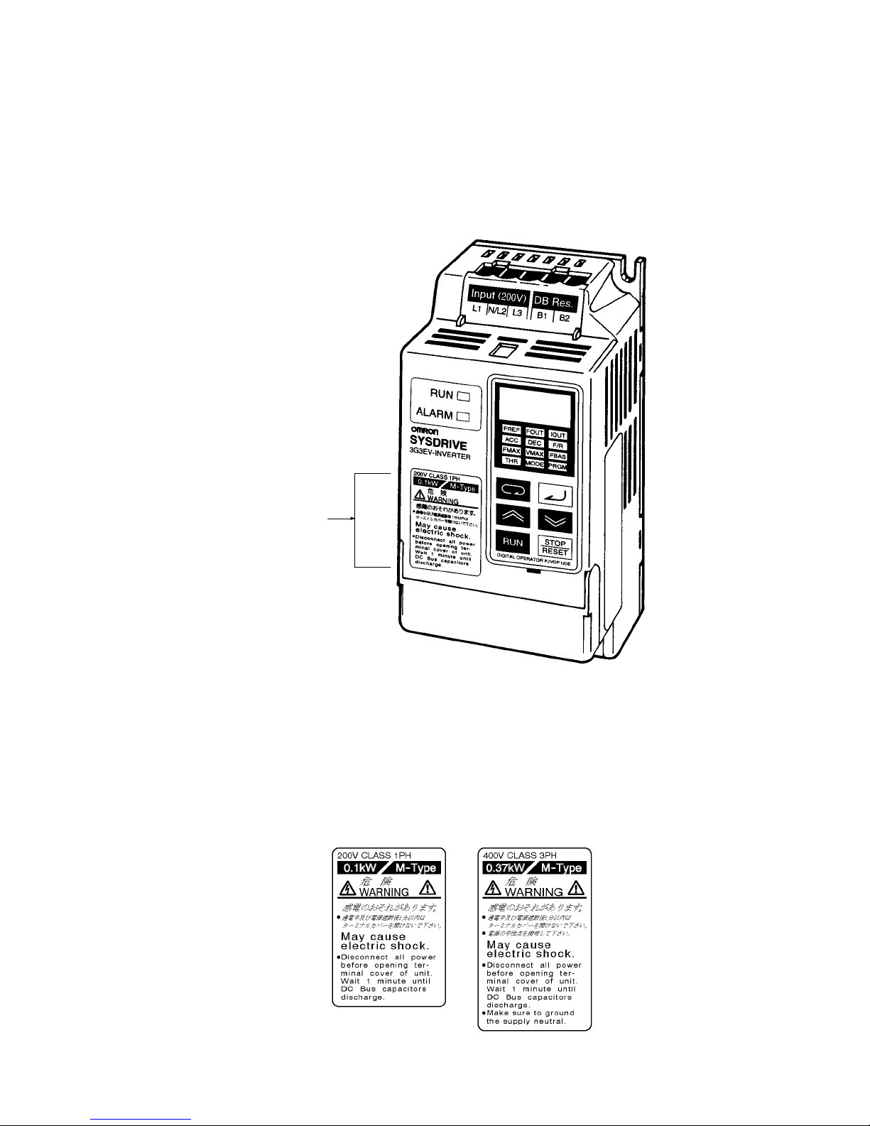
Warning Label
A warning label is attached to the product as shown in the following illustration. Be sure to
observe the precautionary items specified on the label.
Warning label
Contents of Warning Label
Read and Understand this Manual
Please read and understand this manual before using the product. Please consult your OMRON
representative if you have any questions or comments.
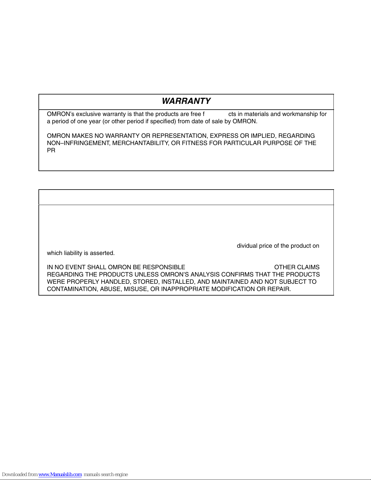
Warranty and Limitations of Liability
WARRANTY
БББББББББББББББББББББББББББББББ
Á
БББББББББББББББББББББББББББББББ
Á
БББББББББББББББББББББББББББББББ
Á
БББББББББББББББББББББББББББББББ
Á
БББББББББББББББББББББББББББББББ
Á
БББББББББББББББББББББББББББББББ
Á
OMRON’s exclusive warranty is that the products are free from defects in materials and workmanship for
a period of one year (or other period if specified) from date of sale by OMRON.
OMRON MAKES NO WARRANTY OR REPRESENTATION, EXPRESS OR IMPLIED, REGARDING
NON–INFRINGEMENT, MERCHANTABILITY, OR FITNESS FOR PARTICULAR PURPOSE OF THE
PRODUCTS. ANY BUYER OR USER ACKNOWLEDGES THAT THE BUYER OR USER ALONE HAS
DETERMINED THAT THE PRODUCTS WILL SUITABLY MEET THE REQUIREMENTS OF THEIR
INTENDED USE. OMRON DISCLAIMS ALL OTHER WARRANTIES, EXPRESS OR IMPLIED.
БББББББББББББББББББББББББББББББ
Á
LIMITATIONS OF LIABILITY
БББББББББББББББББББББББББББББББ
Á
БББББББББББББББББББББББББББББББ
Á
БББББББББББББББББББББББББББББББ
Á
БББББББББББББББББББББББББББББББ
Á
БББББББББББББББББББББББББББББББ
Á
БББББББББББББББББББББББББББББББ
Á
БББББББББББББББББББББББББББББББ
Á
БББББББББББББББББББББББББББББББ
Á
OMRON SHALL NOT BE RESPONSIBLE FOR SPECIAL, INDIRECT, OR CONSEQUENTIAL
DAMAGES, LOSS OF PROFITS OR COMMERCIAL LOSS IN ANY WAY CONNECTED WITH THE
PRODUCTS, WHETHER SUCH CLAIM IS BASED ON CONTRACT, WARRANTY, NEGLIGENCE, OR
STRICT LIABILITY.
In no event shall the responsibility of OMRON for any act exceed the individual price of the product on
which liability is asserted.
IN NO EVENT SHALL OMRON BE RESPONSIBLE FOR WARRANTY, REPAIR, OR OTHER CLAIMS
REGARDING THE PRODUCTS UNLESS OMRON’S ANALYSIS CONFIRMS THAT THE PRODUCTS
WERE PROPERLY HANDLED, STORED, INSTALLED, AND MAINTAINED AND NOT SUBJECT TO
CONTAMINATION, ABUSE, MISUSE, OR INAPPROPRIATE MODIFICATION OR REPAIR.
Application Considerations
SUITABILITY FOR USE
БББББББББББББББББББББББББББББББ
Á
БББББББББББББББББББББББББББББББ
Á
БББББББББББББББББББББББББББББББ
Á
БББББББББББББББББББББББББББББББ
Á
БББББББББББББББББББББББББББББББ
Á
БББББББББББББББББББББББББББББББ
Á
БББББББББББББББББББББББББББББББ
Á
БББББББББББББББББББББББББББББББ
Á
БББББББББББББББББББББББББББББББ
Á
БББББББББББББББББББББББББББББББ
Á
БББББББББББББББББББББББББББББББ
Á
БББББББББББББББББББББББББББББББ
Á
БББББББББББББББББББББББББББББББ
Á
БББББББББББББББББББББББББББББББ
Á
БББББББББББББББББББББББББББББББ
Á
БББББББББББББББББББББББББББББББ
Á
БББББББББББББББББББББББББББББББ
Á
БББББББББББББББББББББББББББББББ
Á
БББББББББББББББББББББББББББББББ
Á
БББББББББББББББББББББББББББББББ
Á
OMRON shall not be responsible for conformity with any standards, codes, or regulations that apply to
the combination of products in the customer’s application or use of the products.
At the customer’s request, OMRON will provide applicable third party certification documents identifying
ratings and limitations of use that apply to the products. This information by itself is not sufficient for a
complete determination of the suitability of the products in combination with the end product, machine,
system, or other application or use.
The following are some examples of applications for which particular attention must be given. This is not
intended to be an exhaustive list of all possible uses of the products, nor is it intended to imply that the
uses listed may be suitable for the products:
• Outdoor use, uses involving potential chemical contamination or electrical interference, or conditions
or uses not described in this manual.
• Nuclear energy control systems, combustion systems, railroad systems, aviation systems, medical
equipment, amusement machines, vehicles, safety equipment, and installations subject to separate
industry or government regulations.
• Systems, machines, and equipment that could present a risk to life or property.
Please know and observe all prohibitions of use applicable to the products.
NEVER USE THE PRODUCTS FOR AN APPLICATION INVOLVING SERIOUS RISK TO LIFE OR
PROPERTY WITHOUT ENSURING THAT THE SYSTEM AS A WHOLE HAS BEEN DESIGNED TO
ADDRESS THE RISKS, AND THAT THE OMRON PRODUCTS ARE PROPERLY RATED AND
INSTALLED FOR THE INTENDED USE WITHIN THE OVERALL EQUIPMENT OR SYSTEM.
БББББББББББББББББББББББББББББББ
Á
PROGRAMMABLE PRODUCTS
БББББББББББББББББББББББББББББББ
Á
OMRON shall not be responsible for the user’s programming of a programmable product, or any
consequence thereof.
Disclaimers
БББББББББББББББББББББББББББББББ
Á
CHANGE IN SPECIFICATIONS
БББББББББББББББББББББББББББББББ
Á
БББББББББББББББББББББББББББББББ
Á
БББББББББББББББББББББББББББББББ
Á
БББББББББББББББББББББББББББББББ
Á
БББББББББББББББББББББББББББББББ
Á
Product specifications and accessories may be changed at any time based on improvements and other
reasons.
It is our practice to change model numbers when published ratings or features are changed, or when
significant construction changes are made. However, some specifications of the products may be
changed without any notice. When in doubt, special model numbers may be assigned to fix or establish
key specifications for your application on your request. Please consult with your OMRON representative
at any time to confirm actual specifications of purchased products.
БББББББББББББББББББББББББББББББ
Á
DIMENSIONS AND WEIGHTS
БББББББББББББББББББББББББББББББ
Á
Dimensions and weights are nominal and are not to be used for manufacturing purposes, even when
tolerances are shown.
PERFORMANCE DATA
БББББББББББББББББББББББББББББББ
Á
БББББББББББББББББББББББББББББББ
Á
БББББББББББББББББББББББББББББББ
Á
Performance data given in this manual is provided as a guide for the user in determining suitability and
does not constitute a warranty. It may represent the result of OMRON’s test conditions, and the users
must correlate it to actual application requirements. Actual performance is subject to the OMRON
Warranty and Limitations of Liability.
БББББББББББББББББББББББББББББББ
Á
ERRORS AND OMISSIONS
БББББББББББББББББББББББББББББББ
Á
The information in this manual has been carefully checked and is believed to be accurate; however, no
responsibility is assumed for clerical, typographical, or proofreading errors, or omissions.

INSTALLATION MANUAL
(Standard/Multi-function Model)
(EC Directives Models)
SYSDRIVE 3G3EV-Ajjjj-CUE

Table of Contents
Chapter 1. Getting Started 1-1. . . . . . . . . . . . . . . . . . . . . . . . . . . . . . . . . . .
1-1 Items to be Checked when Unpacking 1-2. . . . . . . . . . . . . . . . . . . . . . . . . . . . . . . . . . . . . . . . . . .
1-2 Precautions 1-3. . . . . . . . . . . . . . . . . . . . . . . . . . . . . . . . . . . . . . . . . . . . . . . . . . . . . . . . . . . . . . . . .
Chapter 2. Overview 2-1. . . . . . . . . . . . . . . . . . . . . . . . . . . . . . . . . . . . . . . .
2-1 Features 2-2. . . . . . . . . . . . . . . . . . . . . . . . . . . . . . . . . . . . . . . . . . . . . . . . . . . . . . . . . . . . . . . . . . .
2-2 Nomenclature 2-4. . . . . . . . . . . . . . . . . . . . . . . . . . . . . . . . . . . . . . . . . . . . . . . . . . . . . . . . . . . . . . .
Chapter 3. Design 3-1. . . . . . . . . . . . . . . . . . . . . . . . . . . . . . . . . . . . . . . . . .
3-1 Installation 3-2. . . . . . . . . . . . . . . . . . . . . . . . . . . . . . . . . . . . . . . . . . . . . . . . . . . . . . . . . . . . . . . . .
3-1-1 Outside/Mounting Dimensions 3-2. . . . . . . . . . . . . . . . . . . . . . . . . . . . . . . . . . . . . . . . . . .
3-1-2 Installation Conditions 3-4. . . . . . . . . . . . . . . . . . . . . . . . . . . . . . . . . . . . . . . . . . . . . . . . .
3-2 Wiring 3-6. . . . . . . . . . . . . . . . . . . . . . . . . . . . . . . . . . . . . . . . . . . . . . . . . . . . . . . . . . . . . . . . . . . .
3-2-1 Terminal Blocks 3-7. . . . . . . . . . . . . . . . . . . . . . . . . . . . . . . . . . . . . . . . . . . . . . . . . . . . . .
3-2-2 Wiring Around the Main Circuit 3-11. . . . . . . . . . . . . . . . . . . . . . . . . . . . . . . . . . . . . . . . .
3-2-3 Wiring Control Circuit Terminals 3-19. . . . . . . . . . . . . . . . . . . . . . . . . . . . . . . . . . . . . . . . .
Chapter 4. Specifications 4-1. . . . . . . . . . . . . . . . . . . . . . . . . . . . . . . . . . . .
4-1 Specifications of Main Unit 4-2. . . . . . . . . . . . . . . . . . . . . . . . . . . . . . . . . . . . . . . . . . . . . . . . . . . .
4-2 Specifications of Noise Filter 4-6. . . . . . . . . . . . . . . . . . . . . . . . . . . . . . . . . . . . . . . . . . . . . . . . . .
Index I-1. . . . . . . . . . . . . . . . . . . . . . . . . . . . . . . . . . . . . . . . . .
Revision History R-1. . . . . . . . . . . . . . . . . . . . . . . . . . . . . . . . .

Chapter 1
Getting Started
1-1 Items to be Checked when Unpacking
1-2 Precautions
1
1-2
1-1 Items to be Checked when Unpacking
H Checking the Product
On delivery, always check that the delivered product is the SYSDRIVE 3G3EV Inverter that you ordered.
Should you find any problems with the product, immediately contact your nearest local sales representative.
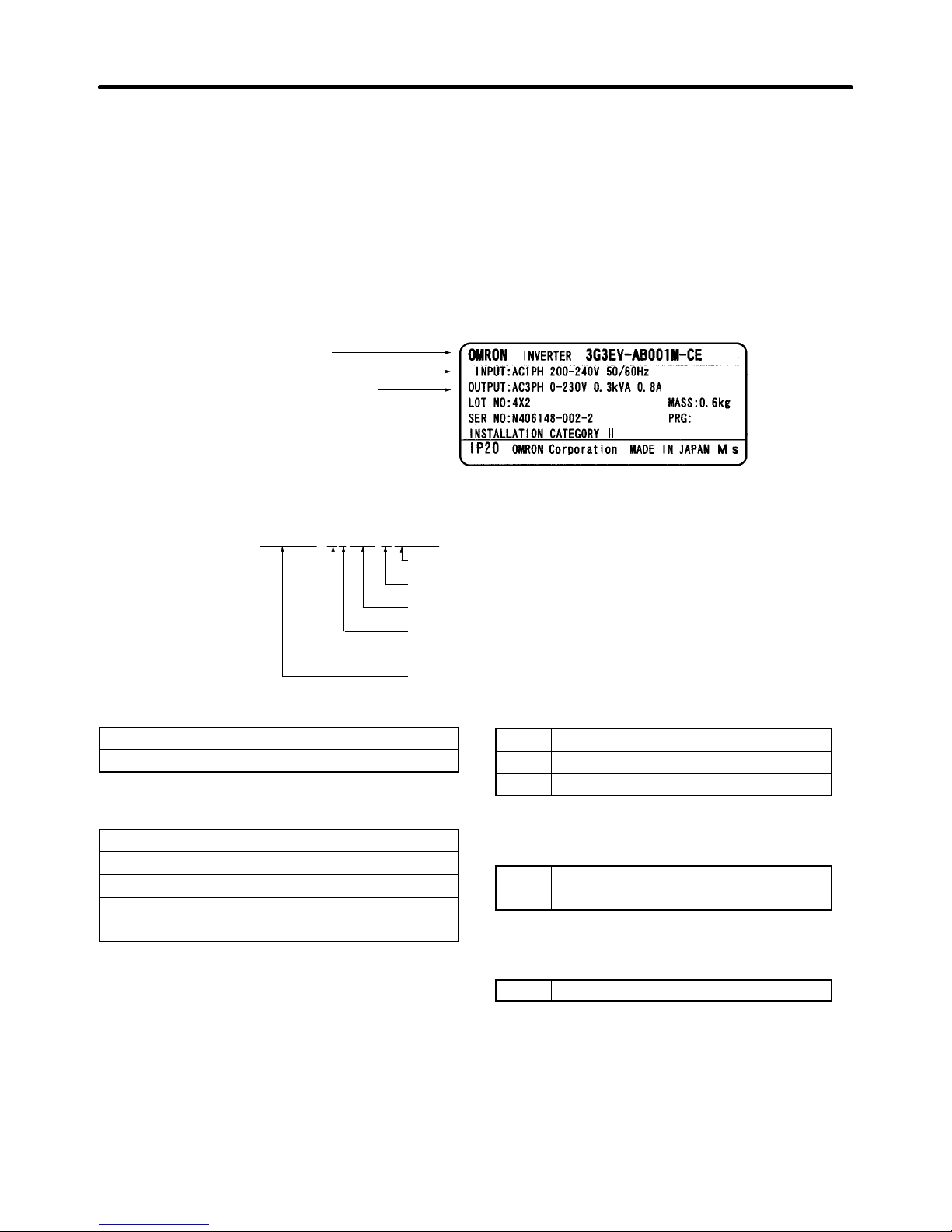
D Checking the Nameplate
Inverter model
Input specifications
Output specifications
D Checking the Model
3G3EV-A4002M-CUE
Special Specification
Specification
Maximum applicable motor capacity
Voltage class
Installation type/Option
Series name: 3G3EV Series
Specifications
Blank Standard model
M Multi-function model
Maximum Applicable Motor Capacity
001 0.1 kW
002 0.2 (0.37) kW
004 0.4 (0.55) kW
007 0.75 (1.1) kW
015 1.5 kW
Note The figures in parentheses indicate
capacities for 400-VAC class models.
Voltage Class
2 Three-phase 200-VAC input
B Single/Three-phase 200-VAC input
4 Three-phase 400-VAC input
Installation Type/Option
A Panel mounting
P Option
Special Specification
-CUE UL/CUL and EC Directives Models
D Checking for Damage
Check the overall appearance and check for damage or scratches resulting from transportation.
H Checking Accessories
Note that this manual and the User’s Manual are the accessories provided with the 3G3EV (Multi-function Model). Set screws and other necessary parts must be prepared by customers.
Getting Started Chapter 1
1-3
1-2 Precautions
To ensure safe operation of the 3G3EV, note the following items:
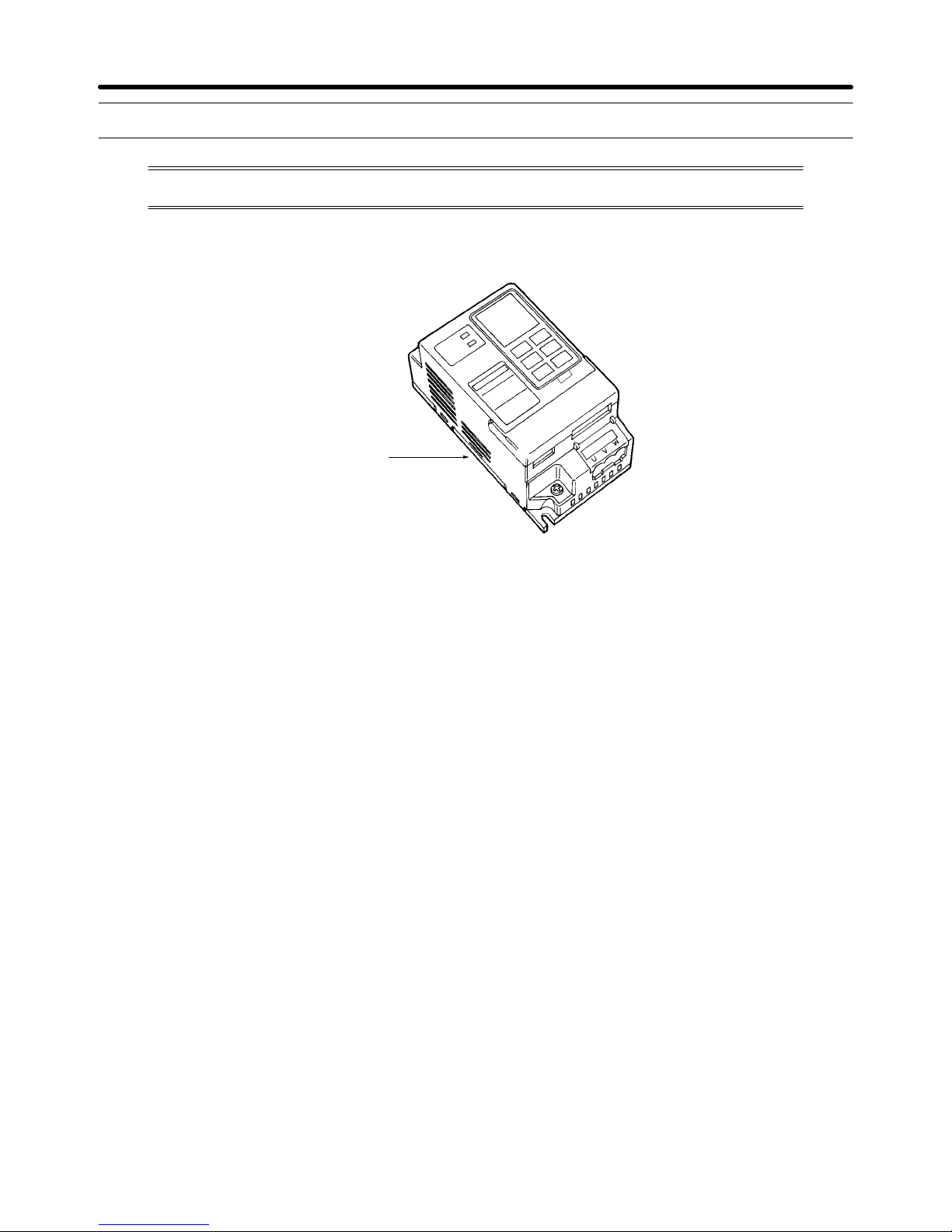
H Always Hold the Heat Sink During Removal
When moving the 3G3EV, always hold the heat sink (aluminum portion on the rear of the Unit).
Heat sink
H Watch Out for Residual Voltage On Charged Portions
After the power is turned off, residual voltage remains in the capacitor inside the Inverter. Therefore,
touching terminals immediately after turning the power off may cause an electrical shock.
If an inspection or some other task is to be performed, always wait at least one minute from the time all
indicators on the front panel go off.
(Note that this warning is applicable whenever you perform any task after turning the main circuit off.)
H Do Not Remove the Digital Operator When the Main Circuit is Still On.
Always turn the main circuit off before removing the Digital Operator.
Removing the Digital Operator with the main circuit ON may cause an electrical shock and damage the
equipment.
H Do Not Modify Wiring or Check Signals When the Main Circuit is ON
Always turn the main circuit off before modifying wiring or checking signals.
Touching terminals while the main circuit is on may cause an electrical shock and damage the equipment.
H Do Not Conduct a Dielectric Strength Test
Because the 3G3EV Inverter is an electronic control unit using semiconductor, never conduct a dielectric strength test or an insulation resistance test for the control circuit.
H Modify Constant Settings Correctly
Always modify the constant settings according to the procedures described in this manual and the
User’s Manual.
Getting Started Chapter 1

Chapter 2
Overview
2-1 Features
2-2 Nomenclature
2
2-2
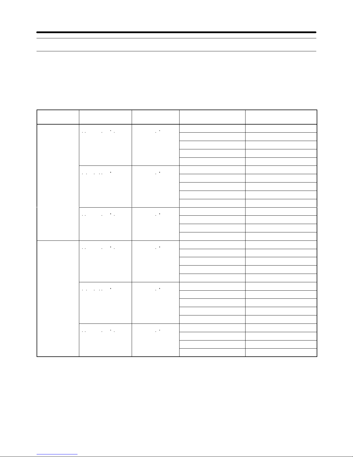
2-1 Features
H 3G3EV-series Models (EC Directives Models)
Standard and multi-function 3G3EV-series Inverters of EC Directives Models are available.
The maximum applicable motor capacities for the 200-VAC class are 0.1 to 1.5 kW (5 models) and 0.2 to
1.5 kW (4 models) for the 400-VAC class.
Type Voltage class Enclosure
rating
Max. applicable motor
capacity
Model
Standard 200-VAC input
Enclosed panel
0.1 kW 3G3EV-A2001-CUE
p
(three-phase)
p
mounted
0.2 kW 3G3EV-A2002-CUE
0.4 kW 3G3EV-A2004-CUE
0.75 kW 3G3EV-A2007-CUE
1.5 kW 3G3EV-A2015-CUE
200-VAC input
Enclosed panel
0.1 kW 3G3EV-AB001-CUE
p
(single/three-
p
mounted
0.2 kW 3G3EV-AB002-CUE
phase
)
0.4 kW 3G3EV-AB004-CUE
0.75 kW 3G3EV-AB007-CUE
1.5 kW 3G3EV-AB015-CUE
400-VAC input
Enclosed panel
0.2 (0.37) kW 3G3EV-A4002-CUE
p
(three-phase)
p
mounted
0.4 (0.55) kW 3G3EV-A4004-CUE
0.75 (1.1) kW 3G3EV-A4007-CUE
1.5 kW 3G3EV-A4015-CUE
Multi-function 200-VAC input
Enclosed panel
0.1 kW 3G3EV-A2001M-CUE
p
(three-phase)
p
mounted
0.2 kW 3G3EV-A2002M-CUE
0.4 kW 3G3EV-A2004M-CUE
0.75 kW 3G3EV-A2007M-CUE
1.5 kW 3G3EV-A2015M-CUE
200-VAC input
Enclosed panel
0.1 kW 3G3EV-AB001M-CUE
p
(single/three-
p
mounted
0.2 kW 3G3EV-AB002M-CUE
phase
)
0.4 kW 3G3EV-AB004M-CUE
0.75 kW 3G3EV-AB007M-CUE
1.5 kW 3G3EV-AB015M-CUE
400-VAC input
Enclosed panel
0.2 (0.37) kW 3G3EV-A4002M-CUE
p
(three-phase)
p
mounted
0.4 (0.55) kW 3G3EV-A4004M-CUE
0.75 (1.1) kW 3G3EV-A4007M-CUE
1.5 kW 3G3EV-A4015M-CUE
Note Model numbers with a suffix of “-CUE” indicate models approved by UL. (Approval has not been
obtained for models with a model number suffix of “-CE.”)
Overview Chapter 2

2-3
H LVD and EMC Directives
The SYSDRIVE EC Directives Models conform to the LVD (prEN50178) and the EMC (EN50081-2,
EN50082-2) Directives.
However, when the product is built into a unit, the connected switches, optional items, or motors may not
satisfy these Directives. In such a case, either use components that meet the Directives or take appropriate countermeasures such as providing surge killers or other noise prevention devices.
H Required Conditions
There are several conditions that must be satisfied for this Inverter to conform to the LVD and EMC
Directives. To satisfy the Directives, meet the instructions in this manual for the following installation
conditions.
• Installation of noise filters and clamp core.
• Shield braided cables must be used for input and output cables.
Limitations on the lengths of cables.
• Installation of recommended fuses on the input side.
H Other Functions
This manual describes installation and wiring methods for conforming to the LVD and EMC Directives.
Refer to the User’s Manual for detailed information on the functions of the Inverter.
• 3G3EV-series Standard Model:
SYSDRIVE 3G3EV Compact Low-noise Inverter (I011-E1)
• 3G3EV-series Multi-function Model:
SYSDRIVE 3G3EV Compact Low-noise Inverter (I013-E1)
Overview Chapter 2
2-4
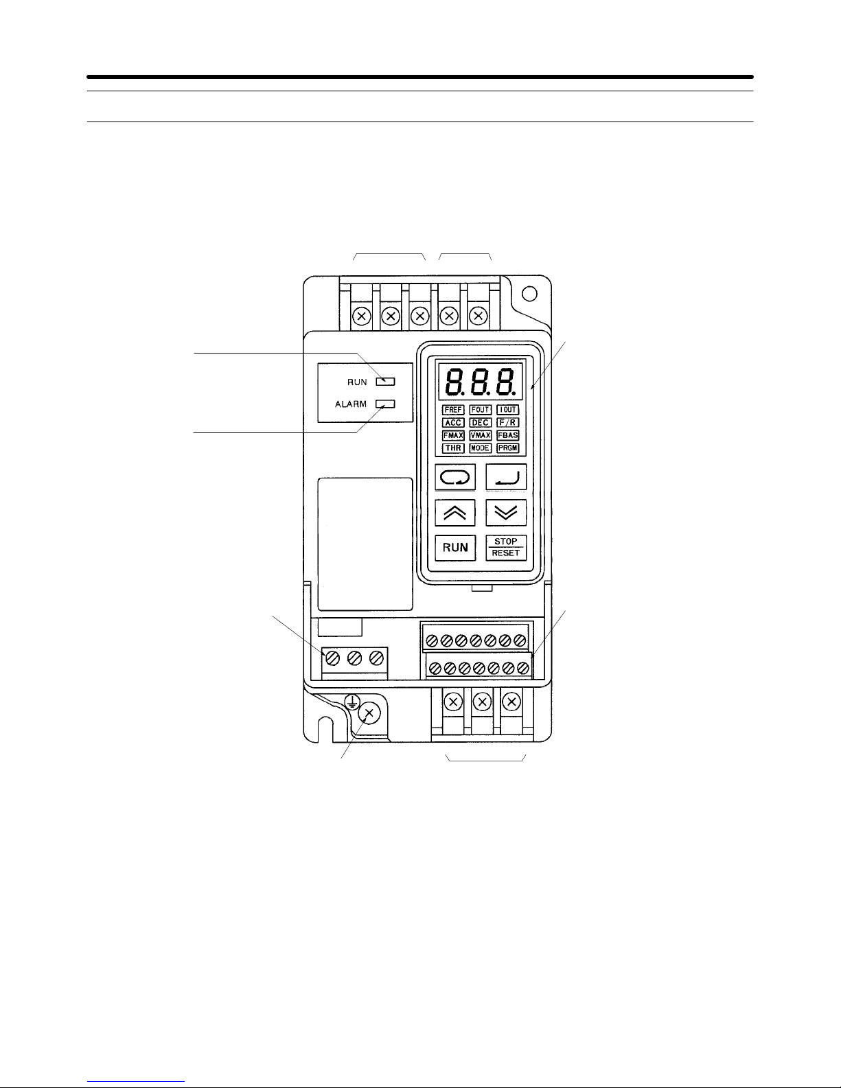
2-2 Nomenclature
H Main Unit
Main Circuit Terminals (Input)
Power input
terminals
Braking resistor
connection terminals
Run indicator
Alarm indicator
Control circuit terminals (output)
Ground terminal
Main Circuit Terminals (Output)
Motor output
terminals
Digital Operator
Control circuit terminals
(input/output)
MA MB MC
SF SR S1 SC FS FR FC
L1 N/L2 L3 B1 B2
S2 S3 SC AM AC PA PC
UV W
Note This diagram shows the Inverter with all terminal block covers removed.
The standard Inverters are not provided with the upper terminal block (S2 to PC).
Overview Chapter 2
 Loading...