


TABLE OF CONTENTS
SECTION PAGE
1. SYSTEM START AND SHUT DOWN.......................................................................................................................................................1
1.1 PROGRAM START .........................................................................................................................................................................1
1.2 PROGRAM EXIT ............................................................................................................................................................................. 1
1.3 SHUT DOWN...................................................................................................................................................................................2
1.4 SHELL MODE..................................................................................................................................................................................2
1.5 EZ update ........................................................................................................................................................................................ 5
2. SETUP ......................................................................................................................................................................................................8
2.1 SETUP SCREEN............................................................................................................................................................................. 8
2.2 SETUP MENU BAR......................................................................................................................................................................... 9
2.3 CAMERA SETUP ..........................................................................................................................................................................10
2.4 RECORD SPEED SETUP ............................................................................................................................................................. 11
2.5 RECORD SCHEDULE SETUP......................................................................................................................................................13
2.6 MOTION SETUP ...........................................................................................................................................................................15
2.7 AV MONITOR ................................................................................................................................................................................16
2.8 SENSOR & ALARM SETUP.......................................................................................................................................................... 17
2.9 AUDIO SETUP ..............................................................................................................................................................................18
2.10 ACCOUNT SETUP ...................................................................................................................................................................... 19
2.11 NETWORK SETUP .....................................................................................................................................................................21
2.12 DIET MODE SETUP.................................................................................................................................................................... 23
2.13 ETC SETUP.................................................................................................................................................................................26
2.14 SOFT KEYBOARD ...................................................................................................................................................................... 29
2.15 CONFIRM & CANCEL ................................................................................................................................................................. 29
3. MONITORING SCREEN.........................................................................................................................................................................30
3.1 INTRODUCTION ...........................................................................................................................................................................30
3.2 SCREEN DIVISION SETUP .......................................................................................................................................................... 31
3.3 RECORDING STATUS..................................................................................................................................................................33
3.4 CAMERA CONTROL..................................................................................................................................................................... 34
3.5 REAL TIME AUDIO .......................................................................................................................................................................35
3.6 DVR INFORMATION WINDOW ....................................................................................................................................................35
3.7 LOG WINDOW ..............................................................................................................................................................................36
3.8 EVENT & LOG HISTORY WINDOW ............................................................................................................................................. 36
3.9 CONNECTED USER STATUS...................................................................................................................................................... 40
4. SEARCH ................................................................................................................................................................................................. 41
4.1 INTRODUCTION ...........................................................................................................................................................................41
4.2 SEARCH SCREEN FORMATION .................................................................................................................................................42
4.3 VIDEO SEARCH............................................................................................................................................................................43

4.4 PLAY CONTROLS.........................................................................................................................................................................44
4.5 AUDIO PLAY .................................................................................................................................................................................45
4.6 IMAGE SAVE.................................................................................................................................................................................46
4.7 IMAGE PRINT ...............................................................................................................................................................................46
5. MULTI – SEARCH ..................................................................................................................................................................................47
5.1 MULTI - SEARCH.......................................................................................................................................................................... 47
5.2 INTRODUCTION ...........................................................................................................................................................................48
5.3 MULTI - SEARCH.......................................................................................................................................................................... 50
5.4 ZOOM IN MODE............................................................................................................................................................................52
5.5 BOOKMARK ..................................................................................................................................................................................53
6. PANORAMA SEARCH ...........................................................................................................................................................................54
6.1 PANORAMA SEARCH SCREEN .................................................................................................................................................. 54
6.2 INTRODUCTION ...........................................................................................................................................................................55
6.3 ADVANCED SEARCH................................................................................................................................................................... 57
6.4 IMAGE PRINT ...............................................................................................................................................................................58
6.5 PANORAMA SCREEN ZOOM ......................................................................................................................................................59
6-6.IMAGE ADJUSTMENT.................................................................................................................................................................. 60
6.7 SMART SEARCH .......................................................................................................................................................................... 61
7. FILE BACKUP.........................................................................................................................................................................................62
7.1 ENTERING THE BACKUP SCREEN ............................................................................................................................................62
7.2 INTRODUCTION ...........................................................................................................................................................................63
7.3 BACKUP SELECTED FILE ...........................................................................................................................................................64
7.4 BACKUP BY TIME.........................................................................................................................................................................65
7.5 FILE SAVING STRUCTURE OF OVR-DVR FOR BACKUP .........................................................................................................66
8. APPENDIX 1........................................................................................................................................................................................... 67
8.1 OPEN PROTOCOL .......................................................................................................................................................................67
8.2 STARTING OPEN PROTOCOL ....................................................................................................................................................67
8.3 OPEN PROTOCOL SETUP ..........................................................................................................................................................68
8.4 OPEN PROTOCOL EXAMPLE .....................................................................................................................................................69
8.5 HEXADEMICAL NUMERIC SYSTEM ...........................................................................................................................................71
9. APPENDIX 2........................................................................................................................................................................................... 72
9.1 DVR WEB WERVICE .................................................................................................................................................................... 72
9.2 WEB VIEWER ...............................................................................................................................................................................72
10.1 TCP / IP filtering...........................................................................................................................................................................74
10.2 TCP/IP setup for ‘TCP/IP filtering’ ...............................................................................................................................................74

1. SYSTEM START AND SHUT DOWN
1
1. SYSTEM START AND SHUT DOWN
1.1 PROGRAM START
After installing the DVR program, it will automatically run when the power is on. The program will be
registered in the ‘START UP’ program list. If you have shut down the program yourself or deleted the
program from the ‘START UP’ program list, please click the program icon on the desktop.
1.2 PROGRAM EXIT
When exiting the program, please exit by pressing the [Exit] button.
You will exit to the desktop.
1 Press [Exit] button on the Monitoring Screen.
2
Select [Admin] on the [USER NAME] and then enter its [PASSWORD].
(The default Password is ‘1’) Then press [OK] and the program will be closed.

1. SYSTEM START AND SHUT DOWN
2
1.3 SHUT DOWN
Any improper shutting down may cause system errors. Please follow these steps to shut down the DVR
system completely and safely.
1
After exiting the DVR program, press [Shutdown] icon.
At the shutdown dialog box, select [Shutdown] and press the [OK] button.
2 Within a minute, the system will be completely shut down.
1.4 SHELL MODE
Omnivision DVR’s provide a shell mode that allows the use of compulsory functions of Windows to keep a
DVR only as a surveillance device. With the shell mode, users cannot operate a program or access the
internet which may interrupt the proper operation of a DVR.
DVR Shell functions are as below.

1. SYSTEM START AND SHUT DOWN
3
A Open Windows Explorer.
B Start the DVR program.
C
When the user starts the [Tool Box], the window below will appear.
In [Tool box], the user can
1. See working programs through ‘Task Manager’.
2. Make/modify the network information of a DVR including IP through ‘Network’.
3. Configure a printer after installing it through ‘Printer’.
4. Set time/date for the recorded images and the search for them through ‘Date/Time’.
5. Configure multimedia devices including a sound card through ‘Multimedia’.
6. See the version number of the DVR software through ‘Version Info’.

1. SYSTEM START AND SHUT DOWN
4
D
User can update the DVR program through the appointed server.
For further information, please refer to ‘p.4, 1.5. EZ update’.
E
The user can make a shortcut icon for a program with the ‘Shortcut’ function.
Double-click the shortcut icon to open the file explorer.
Choose the file and press [Open] button.
The shortcut icon created will be displayed in the top-left of the DVR Shell screen.
To remove the icon, click the icon and press [Delete] key on a keyboard.
F Finish/Restart the system.
G Uninstall the program.
H Command Line

1. SYSTEM START AND SHUT DOWN
5
I
The user can check IP address information.
1.5 EZ update
EZ update ensures you have the most newly updated DVR software. Users should run ‘EZ update’ manually
to update the DVR software.
Please refer below for the operation of ‘EZ update’.
1
Double click the EZ update icon.
2 The following window will appear.

1. SYSTEM START AND SHUT DOWN
6
A Class
Server administrator can appoint classes.
For example, If you are operating a communication server (CS), you must
select SVNS class.
B Product
Select a model among 1000, 1800, 2000, 2200, 4000 and 4200.
For more information on the version or the model, please refer to the tool box.
C Language Select a language.
D CLOSE Stop updating and close the window.
E NEXT Finish the selection and go to the next window.
3
Updated contents are shown. Press [UPDATE] button to process the update and [BACK] button
to go back to previous window.

1. SYSTEM START AND SHUT DOWN
7
4
Update is proceeding.
5
Update is completed. Press [OK] button to finish the update process. When you start the DVR
afterward, the updated information will be automatically applied.
* EZ Update server is not activated by default.
Please contact OmniVision when you need an update for the DVR software.

2. SETUP
8
2. SETUP
2.1 SETUP SCREEN
[Login Screen] [Setup Screen]
1
Press [Setup] button on the Monitoring Screen.
The Login Window will appear.
2
Select Admin on the [User Name] box and enter the password.
(The default password is ‘1’)
Then press [OK] button. The Setup Screen will appear.
NOTE: You can only select the [User Name] by clicking the dropdown menu not by typing.

2. SETUP
9
2.2 SETUP MENU BAR
The setup menu bar consists of 11 setting buttons, a cancel button and a confirm button.
2. SETUP
10
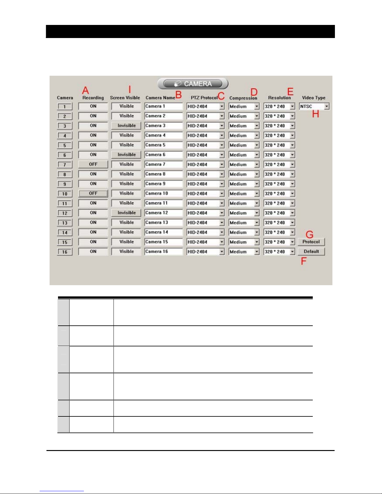
2.3 CAMERA SETUP
The Camera Settings are as followed.
A
Recording
on/off
Turn Recording on/off for each camera.
B Camera name Name each camera. (10 alphabets maximum).
C
PAN/TILT
Driver
Select the Pan/Tilt driver for the PTZ camera.
You can select various drivers for each camera.
D
Compression
rate
Sets the compression rate.
(The higher the rate, the longer the recording time)
E Resolution Select the recording resolution.
F Default Set all settings to default.

2. SETUP
11
G Protocol Able to enter a protocol of RX that is not supported by the system.
H Video signal Select the video signal between NTSC & PAL (Australia).
I Screen Visible
The Administrator can prevent cameras from being displayed on the
Monitoring Screen.
2.4 RECORD SPEED SETUP
Set the recording speed (Frame rate) in this menu.
A CAPTURE
Frames transmitted from connected cameras. For example, if a user
sets the frame rate to 7 for Camera 1, the DVR will receive 7 frames per
second from Camera 1.
B RECORDING
The frames recorded from the frames captured.
Frames recorded have to be equal or less than the frames captured.

2. SETUP
12
C COMMUNICATION
Frames which will be sent over a network (LAN, Dial-up, Broadband,
etc.). However, when the DVR is recording, the frames will be adjusted
automatically depending on the Recording speed.
D APPLY IN A LUMP
Standardize the frame rate values for Capture, Recording and Network
based on the Capture settings.
E
APPLY TO ALL
CAMERAS
Apply settings to all cameras.
F DEFAULT Set all items to the default settings.
G CAMERA Select the camera to configure.
REC TIME
Recording time setting.
(H) Always: Records images all times. Able to set the creation time
of record file every 3~10minutes.
(I) Motion: Starts recording image after motion is detected.
User can set the system to keep recording for amount of time.
(3~10 seconds)
(J) Sensor: Starts recording image after the sensor detects
something. User can set the system to keep recording for
amount of time. (3~10 seconds)
K REC Set each frame for each recording mode, especially with multi-recording

2. SETUP
13
2.5 RECORD SCHEDULE SETUP
Set the recording schedules for each camera in this menu.
1 Camera
Select the camera to record images. You can select multiple cameras by
pressing the [CTRL] key.
2 Select Time Display the selected recording time
3 Day Select Set the recording mode to the selected day
4
Recording Mode
Buttons
Select the recording mode.(Continuous/Motion/Sensor)
5 All Cameras Set all camera recording modes like the selected camera.
6 All days Set all recording schedules like the selected schedule date.
7 Default button Set all to default.

2. SETUP
14
8
Recording
Schedule
Display 24hours of the selected day. User can set the recording schedule on
this.
Schedule settings are as follows.
1 Select a camera to set the recording schedule.
2 Select the recording mode.(Continuous/Motion/Sensor)
3 Drag the mouse to set the time and date for image recording.
4 Repeat step 2 & 3 to set the recording schedule.
5
If you want to set one recording mode on a total day, select the recording mode and press the date
button. (Ex. If I want to set [Continuous] 24hours on Wednesday, select the [Continuous] and
press [Wed])
6
Press [All Cameras] to set all camera schedules same as the settings on one camera.
(Ex. If I want the set all the cameras like camera no.1 like the picture on top, press [All Cameras])
7 If you want to set every day the same, press the [All Days] button.

2. SETUP
15
2.6 MOTION SETUP
Set the motion detection and sensitivity of each camera. User can also set the brightness and contrast of
the camera.
A CAMERA Select camera for setting Motion detecting mode.
B ALL Select Whole image for Motion detecting area.
C CLEAR Clear the last surveillance area that was set.
D ZONE Use part of the camera images for Motion detecting area.
Please refer to below to set the detecting zones.
1. Select a camera.
2. Press [Zone] button.
3. Drag the desired zone. (The zone forms like a square.)
E UNDO Clear all zones.
F SENSITIVITY Set the sensitivity of the motion detection. The system gets more sensitive

2. SETUP
16
when user sets the sensitivity to lower number.
G APPLY ALL Standardize the sensitivity of all cameras as set.
H DEFAULT ALL Default all values.
I DEFAULT Default the values of a selected camera.
J
SCREEN
ADJUSTMENT
User can adjust the brightness and contrast by moving the slide bar or
choosing the number.
K DEFAULT Default the brightness and contrast of selected camera.
L DEFAULT ALL Default the brightness and contrast of all cameras.
M APPLY ALL Standardize the brightness and contrast of all cameras as set.
2.7 AV MONITOR
Set the sensor and alarm for better monitoring. The sensor will only activate when the sensor schedule is
set. The alarm will activate at sensor and motion recording mode.

2. SETUP
17
A
Set capture rotation, rotation period and visible cameras
This function can not be used with OVR4000(T) and OVR4200(T)
B Adjust overlay coordinates, width and height according to AV monitor model.
2.8 SENSOR & ALARM SETUP
Set the sensor and alarm for better monitoring. The sensor will only activate when the sensor schedule is
set. The alarm will activate at sensor and motion recording mode.
[SENSOR SETUP] [ALARM SETUP]
1 One sensor can link with 3 cameras.
2 One camera can link with 3 sensors maximum.
3
Sensor no.16 is used for communication.
It will transmit the DVR recording data to distant places.
This sensor must be made a switch type.
4 You can select a type of sensor either ‘Normal Open’ or ’Normal Close’.
5 You can set 16 alarms maximum for one camera.

2. SETUP
18
2.9 AUDIO SETUP
User can select the camera that will link with 16 audio channels. To record the sound with the recording
image, select the camera and turn the Audio.
A Camera Show the camera number
B Audio After selecting a camera, you can set the audio on/off.
C Default Set all values to [off]
D Audio Type Select “CaptureBoard” when using more than 2 audios.
NOTE:
OVR 2000/2200/4000/4200 only supports 16 audio channels.

2. SETUP
19
2.10 ACCOUNT SETUP
Admin user can add/modify/delete an ID and give it an authority for DVR functions. Previously made IDs are
on the left list and add/modify/delete for an ID is made on the right menu.
Only Admin user can do the account setup.
1 ID Show the all present IDs.
2 AUTHORITY Show authorities given to each ID.

2. SETUP
20
1 ADD Add new ID.
2 MODIFY Modify the authority of previous IDs.
3 DELETE Delete previous IDs.
4 ID Type the ID.
5 PASSWORD Type the password for new or previous ID.
6 OK Type the password above again to be sure.
7
[AUTHORITY]
Selected ID has an authority for a checked function.
1. Setup: An authority for setup.
2. Search: An authority for search.
3. Backup: An authority for backup.
4. DVR Power: An authority for DVR power on/off.
5. Duplex Audio: An authority for using the duplex audio.
6. Remote Setup: An authority for the remote setup.
7. Communication: An authority for remote access to the DVR. (Up to 5 IDs can get this authority.)

2. SETUP
21
8. Safe Mode: An authority for access in Safe Mode. (Safe Mode authority is only given to one ID.)
9. Remote Search: An authority for access in M-Client.
10. Setup: An authority for remote access to the camera channels unit as like as below picture.
8 CLEAR Delete the information.
2.11 NETWORK SETUP
User can set the functions regarding the remote access in the network setup.
1. TCP/IP access on/off
2. Modem access on/off
3. Web Server on/off
4. Connected user status and connect block
5. Maximum guest users

2. SETUP
22
A TCP/IP
(ON): Permits the access through Internet to a DVR.
(OFF): Don’t permit the access through Internet to a DVR.
B MODEM
(ON): Permit the access through a modem.
(OFF) : Don’t permit the access through a modem
C Web Server
(ON): Permit the image transmission using a web browser.
(OFF): Don’t permit the image transmission using a web browser.
Please refer to ‘9. Appendix 2’ for further information on ‘Web Server’.
D Users
User can see connected user IDs, IP and functions in use. User also can
disconnect them with [disconnect] button. User can see the connected user
status by clicking ‘Ctrl + U’ in the main screen.
E GUEST user
User can appoint the maximum number of guest users. There is no big
difference between ‘user’ and ‘Guest user’, but Guest user helps DVR

2. SETUP
23
operates stable by reducing memory working.
F Stream Port Defaulted port: 9999
G Webclient Port Defaulted port: 9995
H Safemode Port Defaulted port : 80
Tip! 1. User can appoint the maximum number of guest users. Guest user has no authority for search and
setup, and up to 100 guest users can connect to a DVR simultaneously. There is not such a big
difference between ‘User’ and ‘Guest user’, but Guest user helps your DVR system operates better
by reducing memory spending.
2. User's have to change TCP/IP filtering after changing Stream Port, WebClient Port and Safemode
Port. Please refer to 10.1 TCP/IP filtering
3. If you changed Stream port you have to change the HTML file in the OVR1000N and OVR1800
folder(C: OVR1800htmlindex.html). Please refer to the below picture.
2.12 DIET MODE SETUP
User can minimize the monitoring screen using the diet mode function.

2. SETUP
24
A
Remote
service
ON: Turns on access to DVR with TCP/IP, Modem.
OFF: Turns off access to DVR with TCP/IP, Modem.
B Rotation
ON: Turns on rotation on diet mode.
OFF: Turns off rotation on diet mode.
C Emergency
Set emergency situation on diet mode.
Return to main page: Goes back to main page for emergency.
Message popup: Pops up a note for emergency.
* No use: Do not use this mode.
D On top
ON: Always puts the monitoring screen on top.
OFF: Turns off this mode.
E
Continuous
recording
ON: Always record images.
OFF: Turns off this mode.
F Motion ON: Use motion recording on Diet mode.

2. SETUP
25
recording OFF: Turn off this mode.
G
Sensor
recording
ON: Use sensor recording on Diet mode.
OFF: Turn off this mode.
H Camera
Select the cameras to use.
(1) All: Select all cameras.
(2) Cancel: Cancel the selected cameras.
I Diet mode(↓) Activate the Diet mode.
Right click on the Diet mode screen to see the menu.
[DIET MODE]
1 Main page Return to the DVR monitoring screen.
2 On top
ON: Always puts the monitoring screen on top.
OFF: Turns off this mode.
3 Rotation
ON: Turns on rotation on diet mode.
OFF: Turns off rotation on diet mode.
4 Exit Exit the Diet mode and turn off the DVR system.

2. SETUP
26
2.13 ETC SETUP
Set various functions on this menu.
A SHELL OPTION
Select DVR Shell mode on/off.
After user changes the setup, the system will restart automatically.
B
Emergency Data
Transfer
If you installed a sensor board, you can not use this function.
If you didn’t install a sensor board, this function will transmit the DVR recording
data to distant places.
C Ctrl + Alt + Del
By setting this function [Off], user can block other users from the system using
[Ctrl + Alt + Delete] function key.
D WATCHDOG
Watchdog is a system that automatically reboots the program when there is an
error on the system.
E
CD-Writer
PROGRAM
To save recorded image files in a CD, you must set the CD Writer program.
(Before this, the CD Writer program must be installed on the Windows)
F
ROTATION
TIME (SEC)
Set the rotation time of the monitoring screen.

2. SETUP
27
G
POWER
OPTION (SEC)
There are 3 types of power options.
Exit to window: Exit to window when the DVR program is over.
DVR system restart: Restart the DVR system when the DVR program is over.
DVR power off: Power off the DVR system when the DVR program is over.
H MATRIX MODE Set location of each screen as user pleases just by dragging.
I
CYCLE FOR
REMOVING
EVENT LOG
To avoid the waste of HDD with event log file, the DVR will delete the event log
information regularly.
J
RECORDING
HDD
If there are multiple HDD's in your system, user can select which HDD to
record,
‘HDD Available’ stands for the available HDD’s, ‘HDD In USE’ stands for the
HDD’s that are in use of recording images.
K CODEC SM4 & MPEG4 for OVR2000, 2200, 4000, 4000(T), 4200, 4200(T), 4400
L
EMERGENCY
POPUP (sec)
When emergency situation (e.g. Motion & Sensor recording mode) in VR, pop-up
window appears in the screen. Only over OVR4000 model.
M
LOW SPEED
LINE
For 56K modem you can choose high A/B/C in the compression of camera set-
up. Please refer to below picture.
N CAPTION
User can choose caption of screen like as time, camera name and recording
type

2. SETUP
28
User can select a CD-Writer program as below.
1 Press ‘Search’ at on the picture above.
2
A window will pop up after pressing
the [Search] button. You can press
[Search] on this window to find the
program file you wan
t.
3 When the search is over, press [OK] to end the setting.
4 Go to the Monitoring screen and press the [Save] button to save.

2. SETUP
29
2.14 SOFT KEYBOARD
The Soft Keyboard is a function that can be used when there is no keyboard connected.
User can use this by clicking the Soft Keyboard button. Move and click the mouse on the Soft Keyboard
to use.
.
2.15 CONFIRM & CANCEL
Confirm Save all settings and exits the program
Cancel Cancel all settings and exits the program

3. MONITORING
30
3. MONITORING
3.1 INTRODUCTION
1 Camera Display Show user the video from related camera.
2 Sensor Indicator
Show user status of sensor inputs. During sensor activation, the related
indicator will turn to red.
3 Camera Button
Allow user to select a camera for control. Pressing any one of these buttons
will show user a selected camera in a single screen view.
4 Alarm Indicator
Show status of sensor outputs. During sensor activation, the related
indicator will turn to red.
5
Screen Division
Button
Allow user to select screen division
6 Exit Button Exit the program.
7 Backup Button Bring up Backup Screen.

3. MONITORING
31
8 Search Button Bring up Search Screen.
9 Setup Button Bring up Setup Screen.
10 Log Window Show DVR status.
11 Brightness/Contrast Allow user to adjust brightness and contrast.
12 Sound Button
Allow user to turn on/off and control the sound.
Right click on sound button will show the sound selection option as below.
13
Camera Control
Panel
Allow user to control a selected camera.
3.2 SCREEN DIVISION SETUP
A Show 4 division screens of camera 1~4.
B Show 4 division screens of camera 1~8.
C Show 4 division screens of camera 9~12.
D Show 4 division screens of camera 13~16.
E Show camera 1~16.
[BASIC DIVISION
F Show other division screens.

3. MONITORING
32
G Show full screen of image. (To exit this mode, right click on the screen) MENU
H
Switch camera images using the mode on. (This function only on
1/4/8division mode)
NOTE:
If user press [ETC] button, user can select more types of the split-screen – 6/7/8/9/10/13.
a Show 6 division screens of camera 1~6.
b Show 6 division screens of camera 6~11.
c Show 6 division screens of camera 11~16.
d Show 7 division screens of camera 1~7.
e Show 7 division screens of camera 5~11.
f Show 7 division screens of camera 10~16.
g Show 8 division screens of camera 1~8.
h Show 8 division screens of camera 9~16.
i Show 9 division screens of camera 1~9.
j Show 9 division screens of camera 8~16.

3. MONITORING
33
A CAMERA NAME
B RECORDING STATUS
k Show 10 division screens of camera 1~10.
l Show 10 division screens of camera 7~16.
m Show 13 division screens of camera 1~13.
n Show 13 division screens of camera 4~16
NOTE: When using DVRX-1000, user can use Light On/Off function in the [ETC] button. In case of
using this function, you can control the light connected with DVRX-1000.
3.3 RECORDING STATUS
B Recording Status
While recording or using audio, some characters will be presented as below.
A: Set the Audio function.
C: Continuous recording
M: Motion recording
S: Sensor recording

3. MONITORING
34
3.4 CAMERA CONTROL
Follow these steps to control the PTZ camera.
1
Select a camera by pressing Camera Button or double-click desired
video from the Monitoring Screen.
2 The selected Camera Button will be indicated pressed.
3 Using Camera Control Panel, user can move the selected camera and also can adjust the lens.
4 Each function of the Camera Control Panel is as bellow.
A Move the selected camera up.
B Move the selected camera down.
C Auto-panning Button
D Move the selected camera left.
E Move the selected camera right.
F Zoom in
G Zoom out
H Focus on a near object.
I Focus on a far object.

3. MONITORING
35
3.5 REAL TIME AUDIO
1 Press the Audio button ‘ON’ on the monitoring screen.
2 Control the volume by setting the slide bar on top of the Audio button.
NOTE:
User can hear the audio only when the audio is set to ‘ON’ in the audio setup.
(Please refer to p.15 - ‘2.8 Audio Setup’)
3.6 DVR INFORMATION WINDOW
You can see the version and kind of the DVR you have, by pressing [Ctrl + V].
You can see the version and the build date of the DVR.

3. MONITORING
36
3.7 LOG WINDOW
Every event occurred in a DVR program is shown on the log window and recorded in a log file. The entire
event can be also shown on the event log window.
Below events are shown on the log window.
1. System Start and Stop
2. Setup Operation
3. Sensor Input and Output Activation
4. Motion Detection and Sensor Output Activation
3.8 EVENT & LOG HISTORY WINDOW
Every important operation will be written in the log file. Follow these steps to trace the log history.
1 Holding down [Ctrl] key, press [E].
2 Event and Log History Window will appear.
3 Press [OK] Button to close this window.

3. MONITORING
37
Below messages are shown on the event log window.
DVR Start Show that the DVR has started.
DVR Exit Show that the DVR has ended.
Setup-In Show that user has entered the setup page.
Setup-Out Show that user has exited the setup page.
Search-in Show that user has entered the search page.
Search-Out Show that user has exited the search page.
Save-in Show that user has entered the save page in Multi Search.
Save-Out Show that user has exited the save page in Multi Search.
Motion Detection Show that there was motion detection.
Sensor Show that the sensor has activated.
Water marking On Show that the Watermarking is started.
Water marking Off Show that the Watermarking is ended.
Remote login Show that there is a remote login on the system.
Remote logout Show that the remote login has ended.
Remote login :
User Failure
Show that an expelled user ID has tried to log in to the system.
Remote login :
Password Failure
Show that a user has entered a wrong password.
Diet mode On Show that the Diet mode has started.
Diet mode Off Show that the Diet mode has ended.

3. MONITORING
38
In the LOG2 you can find setup information like as camera, frame, schedule, motion, audio, network,
authority and ETC.

3. MONITORING
39

3. MONITORING
40
3.9 CONNECTED USER STATUS
You can check the connected user state from remote sites by pressing [Ctrl+U].
1. Present state
2. User ID
3. Remote site (IP)
[Refresh] button: Refresh the present status of connected users.
[Disconnect] button: Disconnected the selected user from the system.
[Close] button: Close the window.

4. SEARCH
41
4. SEARCH
4.1 INTRODUCTION
Follow these steps to enter the search screen
1 Press ‘Search’ button from the monitoring screen.
2 Select a User ID and enter its password.(The default password is ‘1’)
3 Press the [OK] button to enter the Search Screen.

4. SEARCH
42
4.2 SEARCH SCREEN FORMATION
1 Calendar Allow user to select a date to search.
2 Camera Button Allow user to select a camera to search.
3
Recording
Mode Button
Allow user to filter the recorded video by its recording mode.
4 Indexed List
Show user the recorded video list fit to option A ~ C.
User can select a video to replay from the list.
5 Load Button Load a selected video.
6
Search by Time
Button
Allow user to find recorded video included in the selected time range.
7 Exit Button Exit to the Monitoring screen.
8 Multi Search Display the Multi Search Screen
9 Print Button Print sequential images out from a loaded video.

4. SEARCH
43
10 Save Button Save a still image of a loaded video into a floppy disk.
11 Play Controls Allow user to view a loaded video in various speed.
12 Zoom Button Allow user zoom in and out.
13
Video
Information
Show user information of a loaded video.
14 Play Status
Show user the play progress. Using slide bar, user can jump to specific section
of a loaded video.
15 Video Display Display a loaded video.
4.3 VIDEO SEARCH
Follow these steps to search and find video files.
1
Select a date to search using calendar.
(The color of the date with recorded images are in blue)
2 Select a camera to search
3
Select a recording mode for filtering. (All, Always, Motion, Sensor) The
meaning of each buttons is as bellows.
All Search all video regardless to their recording modes.
Always Search only videos recorded in Continuous recording mode.
Motion Search only videos recorded in Motion Detection recording mode.
Sensor Search only videos recorded in Sensor Detection recording mode.

4. SEARCH
44
4
Enter a time range to search by pressing
[Search by Time] button. When there is no
time range selected, show all video of the
selected day.
5 Select a video and press [Load] button.
6 The selected video will appear.
4.4 PLAY CONTROLS
You can control playing by using Play Control buttons.

4. SEARCH
45
4.5 AUDIO PLAY
The followings are how to play a recorded file with audio.
1 Select video file recorded with audio.
2 Load selected data.
3 Turn on or turn off the audio by press “audio button”
4 Adjust audio volume with slide bar.

4. SEARCH
46
4.6 IMAGE SAVE
Follow these steps to save a specific image of the loaded video into a floppy diskette.
1 Press the [Stop] button at the desired frame during play.
2 Insert floppy disk into the FDD.
3 Press [Save] button.
4 Select a graphic format.
5 Pressing [OK] button will save the selected image into the floppy disk.
4.7 IMAGE PRINT
User can print out consecutive 8 images from the loaded video.
Follow these steps to print out images.
1 Press [Stop] button at the desired frame during play
2 Press [Print] button.
3 Adjust the number of frames to print out.
4 Press [OK] button will print out the selected image(s).

5. MULTI - SEARCH
47
5. MULTI – SEARCH
5.1 MULTI - SEARCH
Press the Multi Search button on the bottom of the search screen.
Press this button to move to the multi-search screen.

5. MULTI - SEARCH
48
5.2 INTRODUCTION
You can search the images of not only 1 channel but for up to 16 channels simultaneously.
1
Time display
window
Display current date and time.
2
Split function
Button
Load video data according to each split buttons.
From upper left end, [1~4ch], [5~8ch], [9~12ch], [13~16ch], [Selected 1ch],
[1~9ch], [8~16ch], [All 16ch].
3 Bookmark You can add, delete and find the bookmark frame.
4 Full screen Show the video image on full screen.

5. MULTI - SEARCH
49
5 Sound control Move the slide bar to control the volume. You can also turn on/off the sound.
6 Exit button Exit to Monitoring Screen.
7
Panoramic view
button
After several pictures loaded, user can select specific channel which is wanted
to panoramic view. Selected channel is noticed with red outline. Then press this
button to enter Panoramic view screen of selected channel.
8 Camera
Select the camera no. to search then press the load button. You will see the
loaded image on the screen ready for play.
9
Recording
mode select
button
Show 3 types of recording files on the screen (‘All’ shows all types of recording
files).
10 Play control You can control the video display.
11 Search
The recoding situation on selected date which is selected in Calendar is
displayed by recoding mode with specific colors.
12 Load button Allow user to load video data.
13 Search time
User can select time to search. Click [Time], [Minute], [Second] and [AM/PM] to
adjust a specific time to search.
14 Enlarge search You can enlarge the search screen. This is digital zoom.
15 Update
By clicking this button, you can search for files that have been not updated on
this function.
16 Calendar Allow user to select a date to search.
17 Play screen Display a loaded video.

5. MULTI - SEARCH
50
5.3 MULTI - SEARCH
Follow these steps to use the multi search function.
1
Select a date to search using calendar.
(The date with recorded images turns to blue.)
2 Select a time to search using up-down buttons.
3
Also user can select a time to search by clicking the graph. Selected time is displayed as black
vertical line.
You will see this information on the search screen.
Selected Time Black vertical line.
Always Red zone (Continuous recording mode).
Motion Blue zone (Motion Detection recording mode).
Sensor Green zone (Sensor recording mode).

5. MULTI - SEARCH
51
4 Select recording mode, DVR offers next 4 options.
All Search all video regardless to their recording modes.
Alway
s
Search only video recorded in Continuous recording mode.
Motio
n
Search only video recorded in Motion Detection recording mode
Sens
or
Search only video recorded in Sensor Detection recording mode.
5
Now select the video channel which will be
loaded. Press the video channel, and then
selected buttons are activated. Press again,
and then selected buttons are deactivated.
And User can also select 1 audio channel to
play with. User must set up same audio
channel which is set in Setup screen.
6
Another way to select video channel is
using split buttons. Split button allows user
to load split view type in selected time. Split
buttons don’t need [Load] action. Pressing
split button, selected video data will be
loaded at once.
7
After selecting date, time and channel,
press [Load] button.
8
Selected video data will be appeared like next picture. How to play is same with Search
screen.
9 To load a different image, press the [Stop] button and select another image for loading.

5. MULTI - SEARCH
52
5.4 ZOOM IN MODE
Most of button functions are same. You only shall learn below functions.
Return Return to the multi search screen.
Panorama Turn over to the Panorama zoom screen.
Exit Exit this mode and go back to the monitoring screen.

5. MULTI - SEARCH
53
5.5 BOOKMARK
1 Add
Add the desired frames on the
bookmark list.
Please refer to the right picture.
2 Delete Delete items on the bookmark list.
3 Go To Select one on the bookmark list and go to the appointed frame.
4 Close Close the bookmark menu.

6. PANORAMA SEARCH
54
6. PANORAMA SEARCH
6.1 PANORAMA SEARCH SCREEN
Panorama search is the most advanced searching option. This will help to search more efficiently by
showing a maximum of 18 frames at once.
[PANORAMA SEARCH] SCREEN
Follow these steps to enter the Panorama Search Screen.
1
In the multi-search screen, select the desired footage, then select one channel to enter the
panoramic view screen. Selected images have red out-line.
2 Press ‘Panoramic view’ button from the Multi-search screen.
NOTE:
1. A panoramic view screens allows a user to search 1 channel only. To search various channels,
users can use the Multi-search screen. To search in detail, user can use panoramic view screen.
2. Panoramic view search process is same with Multi-search process. Refer to Multi-search process.

6. PANORAMA SEARCH
55
6.2 INTRODUCTION
1 TIME Show present time.
2
ADDITIONAL
FUNCTIONS
3 VOLUME Control volume on/off
4 EXIT Stop panorama searching and go back to multi search.
5
PLAY CONTROL
BUTTONS
Control the play of images.
A bookmark B Entire screen
C
Enlarge the play
screen
D
Reduce the play
screen
E Image save F Image print
G Advanced search H Smart search(p.56)
A
B
C D E
F
G H

6. PANORAMA SEARCH
56
6 CAMERA
Same function as in the multi search. Only 1ch of audio and video are
available.
7
ENLARGE
SCREEN
Enlarge the screen and shows all the recording screens.
8 SEARCH TIME Select the time period to search. Select hour/minute/second/am/pm for search.
9 LOAD Load video file meet the conditions of camera and time.
10 SEARCH SCREEN Show the selected files from the left calendar in different color modes.
11 CALENDAR Select the date.
12 PLAY SCREEN Display the loaded images.
13 FILE UPDATE Update the recorded files on the list in panorama screen.
14
IMAGE
ADJUSTMENT
Adjust the saved images.
(Please refer to ‘P.55 6-6. Image Adjustment’)

6. PANORAMA SEARCH
57
6.3 ADVANCED SEARCH
A
Go to the next frame. You can move to the frame you want.
B
Zoom in/out. The more you click, the more it zooms.
C
Return to normal screen size.
D
Exit this mode.
E Zoom screen Drag a part in the screen then click to zoom in to that part.

6. PANORAMA SEARCH
58
6.4 IMAGE PRINT
In the panorama mode, user can print desired frames by his/her preference in various modes – 1X2, 2X4,
3X6. First, click frames user want to print out in the panorama search screen. Then the selected frames are
outlined with blue. After that, press [Print] button to open the print window. And then, select the desired print
mode and print the frames.
You can also print in various modes.
1x2 2x4 3x6

6. PANORAMA SEARCH
59
6.5 PANORAMA SCREEN ZOOM
You can also use the zoom in function in the panorama screen. You can see the panorama search screen in
full screen mode and go back to original screen.

6. PANORAMA SEARCH
60
6-6.IMAGE ADJUSTMENT
<IMAGE ADJUSTMENT>
A
BLUR Soften the selected image.
B
SHARPEN
Focus blurry images by increasing the contrast of
adjacent pixels.
C
EDGE DETECT Focus the color boundary line.
D
EMBOSSING
Make the image appear raised or stamped by
converting its fill color to gray and tracing the edges
with the original fill color.
E
GRAY Turn the image to gray-color.
F
LOG Detect the boundary line.
G
EROSION Enlarge the background and reduce the object
H
DILATION Enlarge the object and reduce the background

6. PANORAMA SEARCH
61
I
OPENING Remove the noise and keep the previous size.
J
CLOSING Soften the boundary line and remove the little holes.
K
BRIGHTNESS /
CONTRAST
Control the brightness and contrast of images.
6.7 SMART SEARCH
Smart search can detect movements in consecutive frames. This function is useful for lots of recorded
frames of zones with little movements
A In the panorama search screen, press ‘smart search’ button.
B
Set the zones (up to 5 zones) for motion detecting as motion detecting recording. While playing the
images, the DVR stop playing when it detects movements.
C
Right click the smart search button to set the sensitivity. And with [Default zone] button, user can
cancel the appointed zones.

7. FILE BACKUP
62
7. FILE BACKUP
7.1 ENTERING THE BACKUP SCREEN
1 Press [Backup] button from the monitoring screen.
2 Select a User ID and enter its password. (The default password is ‘1’)
3 Press [OK] button to bring up Backup Screen.

7. FILE BACKUP
63
7.2 INTRODUCTION
User can back up recorded video to a CD-RW, an External HDD, and a DVD.
*To back up recorded video to CD-RW, any kind of CD Writing program will be needed – Ahead Nero, Roxio
CD creator or etc.
*please refer to its manual for further information.
1 Backup Device
Allow user to select a backup media to use among DVD / CD-RW / External
HDD.
2 Path Allow user to select a path to which back up the recorded file.
3 Refresh Button Refresh a file list of the selected backup media.
4
DVD Format
Button
Format a DVD-ROM.
5 Date List
Show user the dates which have recorded video. Select one from the list
and all files of camera 1 in the selected date will be shown by default. Note
that user cannot back up video of current date.
6 Camera Button Allow user to select a camera to back up.
7
Recording Mode
Button
Allow user to select a recording mode to filtered list of video.

7. FILE BACKUP
64
8
Backup Media
Status
Show user the list of video that the selected backup media currently has.
9 File List
Show user the list of video fit to option 5, 6, and 7. User can select video to
back up from this list.
10 File Backup Allow user to back up selected video to the associated backup media.
11 Time Select This option allows user to back up video using time range.
12 Camera Select
Allow user to select a camera to back up. (This option is associated with
[Time Select] option.)
13
Recording Mode
Select
Allow user to select a recording mode of video to back up. (This option is
associated with [Time Select] option.)
14 Backup Button Back up video fit to option 11, 12, 13. .
15 Exit Button Exit to Monitoring Screen.
7.3 BACKUP SELECTED FILE
1 Select a backup media to use.
2 Select a path for backup.
3 Select a desired date to back up from [Date List].
4 Select a camera to back up.
5
Select a recording mode and select video to back
up from [Record File List]

7. FILE BACKUP
65
6
Press [File Backup]. In a while, backup process will
be completed. To exit to Monitoring Screen, press
[Exit] button after backup.
To use HDD or DVD for backup, user must specify the [Drive]. If the media is not formatted please format
that using [HDD FORMAT] or [DVD FORMAT] button prior to backup process.
7.4 BACKUP BY TIME
Follow these steps to back up video using time range.
1 Select a backup media to use.
2 Select a drive letter of the backup media.
3 Select a desired date. Using Time Option, select time range.
4
Select a camera to back up.
(Selecting [ALL] allows user to back up all cameras.)
5 Select a recording mode.
6 Pressing [Backup] button will start backup process.

7. FILE BACKUP
66
7.5 FILE SAVING STRUCTURE OF DVR FOR BACKUP
User is able to get the system to back-up as DVD or CD-RW type. In this case, hardware for the recording
time should be setup and installed by software.( for example, user need to setup CD-RW hardware and
install the software, ‘Easy CD Creator’ to back-up as CD-RW.) The tree-structure of recorded image will be
helpful for users to back-up recorded image files as DVD or CD-RW type. The structure made on D or E
driver is as follows;
To back-up the recorded images from your HDD to other types of media, DVD or CD-RW, please turn off the
DVR program to avoid any troubles. (Recorded images are in D or E drive.)

8. APPENDIX 1
67
8. APPENDIX 1
8.1 OPEN PROTOCOL
Open Protocol (user setup) is a function which enables user to customize and edit P/T/Z cameras’ protocols.
It will make the user feel safe when he/she gets new P/T/Z cameras which is not embedded in DVR.
.
8.2 STARTING OPEN PROTOCOL
User can start the open protocol from the Setup Screen. Follow these steps to edit P/T/Z cameras’ protocols
1 Enter the Setup Screen by pressing [Setup] button on the Monitoring Screen.
2
Press the [Protocol] button on the Setup Screen to bring up the Open Protocol
Window.

8. APPENDIX 1
68
8.3 OPEN PROTOCOL SETUP
Open Protocol Window is as below.
A
Product Name
and Product
List
Enter the product name of the P/T/Z camera to add. Once added, it will be stored
and shown in the list box.
B
Serial
Communicatio
n
User must adjust Baud Rate / Byte Size / Parity Bit / Stop Bit for proper
communication between DVR and P/T/Z camera. Refer to P/T/Z camera manual
to get exact values.
C
Commands
Set
User must input each command values. Please note that user should calculate
each value with the P/T/Z camera manual.
D Camera ID
Select a P/T/Z camera ID to work for. To set multiple cameras up, user must
input each different value for each camera ID. (Ex: When there are 5 P/T/Z
camera named A, user might need to input 5 different Commands Set for each
camera ID from1 to 5.)
E Timer
Check this option when the installed cameras use Timer. (To discern whether
the camera needs this, please refer to P/T/Z camera manual or contact the
manufacturer.)
F
Confirm
Buttons
User can add, delete or modify the values.

8. APPENDIX 1
69
8.4 OPEN PROTOCOL EXAMPLE
When there is a P/T/Z camera named A, user can set the camera up as following.
1. Request P/T/Z protocol manual to the manufacturer
2. Calculate the values for up / down / Left / Right commands and Zoom in /Zoom out /Focus
Near/Focus Far commands with the manual.
3. Press the [New] button to create a new command set.
4. Select the values for Serial Communication. (The most common values is 9600 / 8 / No / 1.))
5. Select a camera ID. (4 channel DVR user checks 1~4 camera IDs).
In this example, we will check camera no.1
6. Enter the calculated command.
7. Each P/T/Z camera has its own protocol commands format but most P/T/Z cameras use hex values for its
commands. So user needs to calculate hex code to get right P/T/Z command values. For example, when
there is a P/T/Z camera which uses 3 bytes P/T/Z commands.

8. APPENDIX 1
70
▒ Checksum is a value which is used for checking if the transmitted value is proper.
Checksum value will be calculated by each unique numerical formula.
Suppose that the left move command of P/T/Z camera A is ‘0x81’ and its ID is ‘0x01’.
And its checksum formula is ‘100 – (ITEM 1 + ITEM 2)’. Then the value for left command is as bellows.
[01 (Camera ID)]+ [81(‘0x’ must be removed.)]+ [100 – (01 + 81) (Checksum)] =01, 81,7e
(Each value should be separated by ‘, ‘.)
Refer to [1.5 Hexadecimal Numeration System] to calculate this in easy way.
8. Repeat step 7 until all the commands needed are filled.
When finished press the [ADD] to save the values.
9. When there is another P/T/Z camera to set up, choose a different Camera ID with the P/T/Z protocol.
And repeat step 6~8.
Press the [Modify] key to apply changed values.
10. To edit, select the model and change the value and press [Modify].
To delete the information, select the model and press [Delete].
11. When finished, press the [Exit] key to close the Open Protocol Window and select the P/T/Z protocol in
the Setup Screen.
ITEM 1 ITEM 2 ITEM 3
Camera ID Command Code Checksum*

8. APPENDIX 1
71
8.5 HEXADEMICAL NUMERIC SYSTEM
User can calculate hexadecimal numbers using a calculator provided with window.
1. Select [Start] → [Program] → [Accessories] → [Calculator].
2. Select [View] -> [Scientific] to expand the default calculator.
3. Check [Hex] and [Byte] to calculate hexadecimal byte numbers.

9. APPENDIX 2
72
9. APPENDIX 2
9.1 DVR WEB SERVICE
Web service of DVR is for remote monitoring without the need for the UniClient software in user’s PC.
It properly works under Internet Explorer version. 5.0. Type the DVR IP in the address window of internet
explorer and below window will appear.
9.2 WEB VIEWER
WEB VIEWER is very accessible because it is receiving images using a web server function. WEB VIEWER
provides easy-access and control instead of search for recorded images and audio function.
WEB VIEWER provides below functions.

9. APPENDIX 2
73
A
Show the images of camera No. 1 ~ 4.
B
Show the images of camera No. 5 ~ 8.
C
Show the images of camera No. 9 ~ 12.
D
Show the images of camera No. 13 ~ 16.
E
Control the P/T/Z camera – Pan/Tilt/Zoom and auto
panning.
F
Control the zoom of selected camera.
To use this function, auto zoom lens should be installed
first.

9. APPENDIX 2
74
G
Control the focus of selected camera.
To use this function, auto zoom lens should be installed
first.
10.1 TCP / IP filtering
What’s ‘TCP/IP filtering’?
‘TCP/IP filtering’ function invests all packets coming into a computer and only accept authorized of them.
(It’s only for a DVR system, not for a PC.)
10.2 TCP/IP setup for ‘TCP/IP filtering’
1. Right-click [My network places] icon and click [Properties].

9. APPENDIX 2
75
2. Right-click [Local Area Connection] or other connection to setup and click [Properties].
3. In [General] tab (in case you selected ‘Local Area Connection’) or another network tab (in case you
selected another connection’ in previous step), select [Internet Protocol (TCP/IP)] and click [Properties].

9. APPENDIX 2
76
4. Click [Advanced].
5. In [Option] tab, select [TCP/IP filtering] and click [Properties].

9. APPENDIX 2
77
6. Follow one of below steps.
1) If you want to use [TCP/IP filtering] over the entire adapters, select [Enable TCP/IP Filtering (All adapters)].
2) If you don’t want, deselect [Enable TCP/IP Filtering (All adapters)].
7. Set [TCP Ports], [UDP Ports] and [IP Protocols] for allowed traffic in accordance with the requirements of
‘TCP/IP filtering’

9. APPENDIX 2
78
In case of the DVR, it only uses ‘9999’, ‘9995’ and ’80’ for [TCP Ports] and [UDP Ports]. So, add ‘9999’,
‘9995’ and ‘80’ for [TCP Ports] and [UDP Ports], and select [Permit Only]. For [IP Protocols], just
select [Permit Only] and remove all the substances.
If you do so, the access by ‘Telnet’ or ‘FTP’ is denied. Accordingly, you can set DVR systems more safely
against viruses or hacking.
* Caution
This [TCP/IP filtering] is only for DVR system.
If you use [TCP/IP filtering] on your PC, it cannot access to the internet.
 Loading...