


 Loading...
IVG Installation and
Troubleshooting Guide
80-JE026-1 B
January 2016
Omnitracs, LLC
717 N. Harwood Street, Suite 1300
Dallas, TX 75201
Copyright © 2015-2016 Omnitracs, LLC. All rights reserved.
Omnitracs is a trademark of Omnitracs, LLC. All other trademarks are the property of their respective owners.
Omnitracs endeavors to ensure that the information in this document is correct and fairly stated, but Omnitracs is not liable for any errors or omissions. Published information may not be up to date, and it is important to confirm current status with Omnitracs.
This technical data may be subject to U.S. and international export, re-export or transfer (export) laws. Diversion contrary to U.S. and international law is strictly prohibited.
80-JE026-1 B
January 2016

Installation Contents
1.Component Overview
2.Activation
3.Installation Planning
4.Display Interface Unit Installation
5.Power I/O Cable Connection
6.Optional Accessories
7.System Verification
8.Appendix Contents
80-JE026-1 Rev. B |
iii |
MAY CONTAIN U.S. AND INTERNATIONAL EXPORT CONTROLLED INFORMATION
Installation Contents
iv |
80-JE026-1 Rev. B |
MAY CONTAIN U.S. AND INTERNATIONAL EXPORT CONTROLLED INFORMATION

Important Safety Information
Safety Definitions
The following Caution and Warning definitions are intended to advise the driver when it is safe to use a display unit.
CAUTION indicates a potentially hazardous situation which, if not avoided, may result in minor or moderate injury. It may also be used to alert against unsafe practices.
WARNING indicates a potentially hazardous situation which, if not avoided, could result in death or serious injury.
Safety Advice
The following Safety Advice is provided for drivers, installers, and application developers who use and/or locate all types of display units.
If you are a Driver, do not use a display unit when the vehicle is in motion.
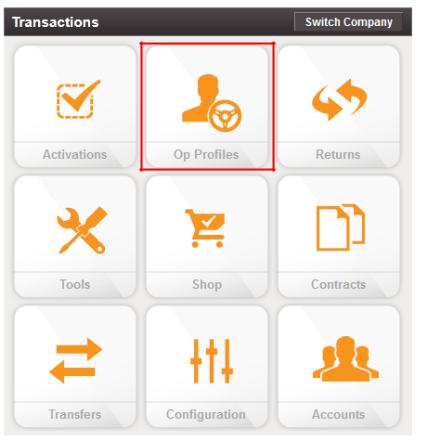
If you are an Installer, do not locate the display unit, including third-party devices, where it obstructs the driver’s field of vision, distracts the driver from the driving task, or interferes with the driver’s operation of controls or instruments. The following is displayed when ignition is turned on.
If you are a Third-party Device Manufacturer or Application Developer, it is your responsibility to provide appropriate warnings regarding the safe use of your device(s) in conjunction with Omnitracs equipment. Applications should not require the driver to divert his attention from the road while driving a vehicle.
80-JE026-1 Rev. B |
v |
MAY CONTAIN U.S. AND INTERNATIONAL EXPORT CONTROLLED INFORMATION
Safety Advice |
Important Safety Information |
vi |
80-JE026-1 Rev. B |
MAY CONTAIN U.S. AND INTERNATIONAL EXPORT CONTROLLED INFORMATION
1
Component Overview
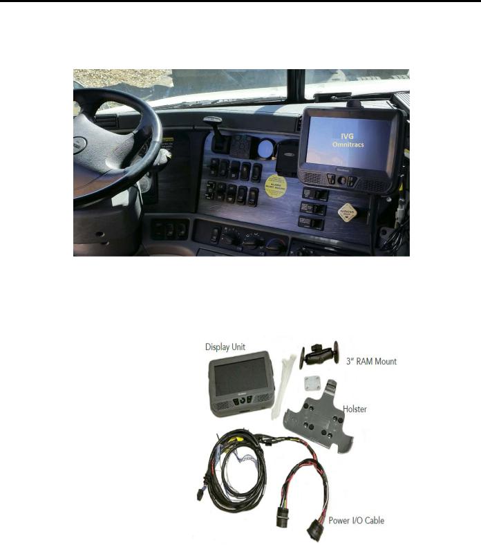
Components
IVG System
•Color, graphical touchscreen display.
•Power I/O cable
•RMA Mount
•Holster
•Hardware
80-JE026-1 Rev. B |
1-1 |
MAY CONTAIN U.S. AND INTERNATIONAL EXPORT CONTROLLED INFORMATION

IVG Display |
Component Overview |
IVG Display
•Color, graphical touchscreen display.
•Virtual on-screen keyboard
•2 USB v2.0 ports on right side
•Micro SD slot on left side
•Home button - brightness and volume controls
•Volume control and brightness control buttons
•Diagnostic LEDs
1-2 |
80-JE026-1 Rev. B |
MAY CONTAIN U.S. AND INTERNATIONAL EXPORT CONTROLLED INFORMATION
Component Overview |
Power I/O Cable (9-pin “Y” cable with standard flanged end) |
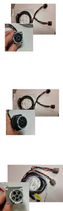
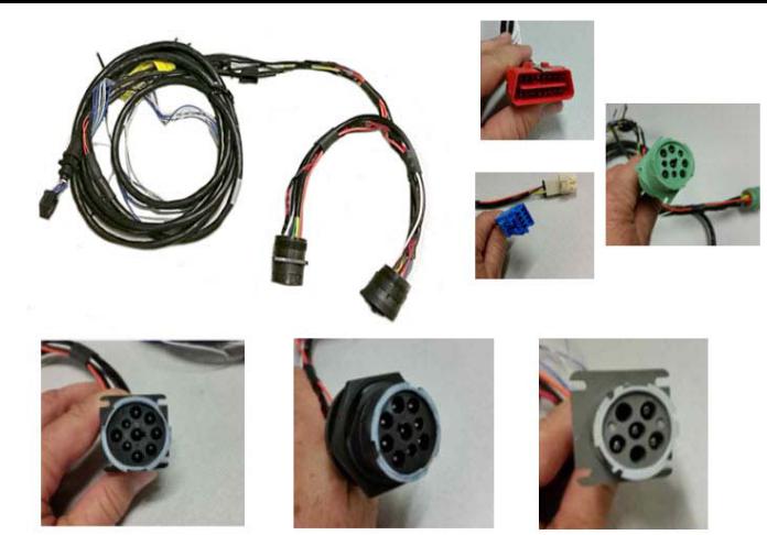
Power I/O Cable (9-pin “Y” cable with standard flanged end)
Connects to a truck’s 9-pin diagnostic connector for power and vehicle data on either J1587 or J1939 data links. This connector has a flange on the
end where connected to the truck’s dash.
• Part number 45-JC364-1A
Power I/O Cable (9-pin “Y” cable with Paccar end)
Connects to a truck’s 9-pin diagnostic connector for power and vehicle data on either J1587 or J1939 data links. This connector is slightly larger than
the flanged connector and has a nut that screws to the outside of the connector to mate it to the truck’s dash.
• Part number 45-JC373-1A
Power I/O Cable (6-pin “Y” cable)
Connects to older model year trucks (1993 to 2003 models) that have a 6-pin diagnostic connector for power and vehicle data on J1708/J1587 data link.
• Part number 45-JC365-1A
80-JE026-1 Rev. B |
1-3 |
MAY CONTAIN U.S. AND INTERNATIONAL EXPORT CONTROLLED INFORMATION

Volvo/Mack J1587/J1708 and J1939
Volvo/Mack J1587/J1708 and J1939
Volvo trucks 2014 or newer with Volvo engines and Mack trucks 2014 or newer with Mack engines will use a diagnostic connector that resembles a standard automotive OBDII connector. This connector provides power and vehicle data for J1939/J1708 (does not use the OBDII protocol).
• Part number 45-JC366-1A
Hino
For late model 2011 and 2012 or newer Hino trucks, you can connect directly to the Hino Telematics connector.
The blue connector is for Japanese manufactured trucks and the white connector is for U.S.manufactured trucks.
• Part number 45-JC375-1A
Power I/O Cable (9-pin “Y” cable 500k - green connectors)
For newer trucks with 500K green diagnostic connectors. Connects to a truck’s 9-pin diagnostic connector for power and J1939 500K vehicle data. This connector has a flange on the end where connected to the truck’s dash.
• Part number 45-JE006-1A
1-4
Component Overview
80-JE026-1 Rev. B
MAY CONTAIN U.S. AND INTERNATIONAL EXPORT CONTROLLED INFORMATION
Component Overview |
Display Holster |
Display Holster
Allows the display to be moved around the cab, or secured on the dash while the truck is operating.
• Part number CV90-JC339-710
RAM Mount
Used for mounting the display/holster to the dash.
• Part number 65-JB313-1
Backing Plate
Always use the supplied backing plate to strengthen the strengthen the support for the mount.
• Part number 50-JB290-1
Product Documentation
You should have also received the following product documentation. Ensure you leave all documents in the cab of the vehicle.
•IVG Getting Started Guide (80-JE014-1)
•HOS DOT Quick Reference Card for IVG (80-JE015-1)
•HOS MOT Quick Reference Card for IVG (80-JE016-1)
80-JE026-1 Rev. B |
1-5 |
MAY CONTAIN U.S. AND INTERNATIONAL EXPORT CONTROLLED INFORMATION
Product Documentation |
Component Overview |
1-6 |
80-JE026-1 Rev. B |
MAY CONTAIN U.S. AND INTERNATIONAL EXPORT CONTROLLED INFORMATION
2
Activation
Activation
Online Activation
Online activation process should have already been completed at least one day prior to installation. This assigns the unit to the correct customer account and registers it on the cellular network.
IVG activation requires access to the Customer Portal. Contractors and Service Centers must work with the customers to activate units.
The online activation process may take up to two hours to complete. To perform the online activation:
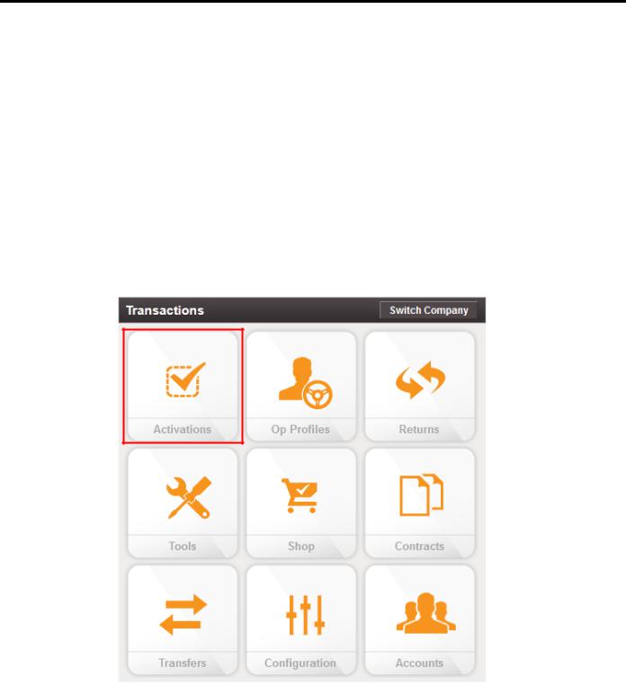
1.Using your supplied credentials, log into: https://customer.myqualcomm.com.
2.Click on the Activations icon on the home page.
80-JE026-1 Rev. B |
2-1 |
MAY CONTAIN U.S. AND INTERNATIONAL EXPORT CONTROLLED INFORMATION
Online Activation |
Activation |
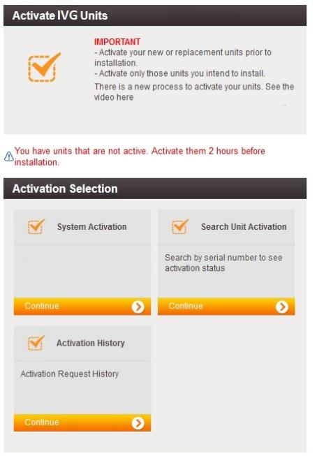
You will then see the main Activations screen. From here click Continue under System Activation.
2-2 |
80-JE026-1 Rev. B |
MAY CONTAIN U.S. AND INTERNATIONAL EXPORT CONTROLLED INFORMATION
Activation |
Application Management |
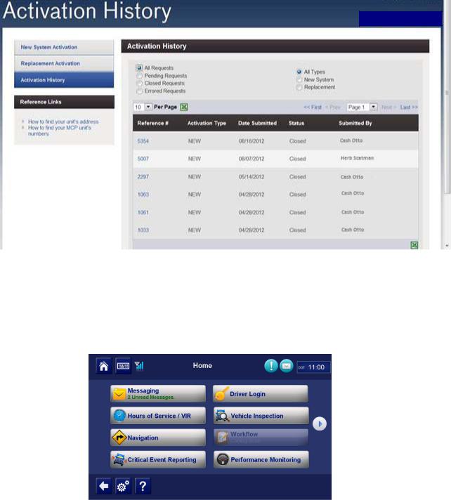
3.To verify that the unit you are installing is activated, click Activation History. Choose what types of activations you want to see. You will then see a screen similar to the following.
Note: You can only search previous replacements.
Application Management
The applications that are made available to a unit are assigned by the customer using an operational profile. A customer can select which applications a given unit should have. Those applications that are not available will not be selectable at the IVG display (grayed out).
80-JE026-1 Rev. B |
2-3 |
MAY CONTAIN U.S. AND INTERNATIONAL EXPORT CONTROLLED INFORMATION
Application Management |
Activation |
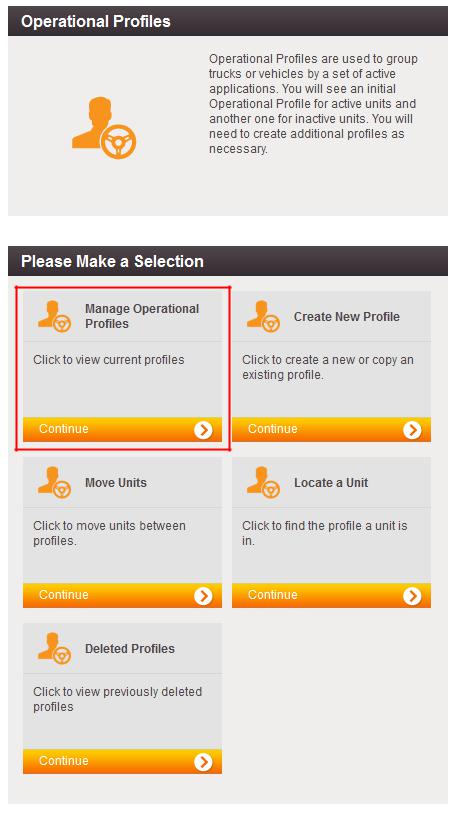
1.To make changes to operational profile, from the Customer Portal home page, click the
Operational Profiles icon.
2-4 |
80-JE026-1 Rev. B |
MAY CONTAIN U.S. AND INTERNATIONAL EXPORT CONTROLLED INFORMATION
Activation |
Application Management |
2.Click Manage Operational Profiles.
80-JE026-1 Rev. B |
2-5 |
MAY CONTAIN U.S. AND INTERNATIONAL EXPORT CONTROLLED INFORMATION

Application Management |
Activation |
3.A screen similar to the below will list the available operational profiles.
2-6 |
80-JE026-1 Rev. B |
MAY CONTAIN U.S. AND INTERNATIONAL EXPORT CONTROLLED INFORMATION

3
Installation Planning
Regulatory Compliance Information
FCC/IC Compliance Statement
This device complies with part 15 of the FCC Rules. Operation is subject to the following two conditions:
(1)This device may not cause harmful interference, and
(2)this device must accept any interference received, including interference that may cause undesired operation.
Note
This equipment has been tested and found to comply with the limits for a Class A digital device, pursuant to part 15 of the FCC Rules. These limits are designed to provide reasonable protection against harmful interference when the equipment is operated in a commercial environment. This equipment generates, uses, and can radiate radio frequency energy and, if not installed and used in accordance with the instruction manual, may cause harmful interference to radio communications. Operation of this equipment in a residential area may cause harmful interference in which case the user will be required to correct the interference at his own expense.
Caution
Any changes or modifications not expressly approved by the party responsible for compliance to this equipment would void the user's authority to operate this device.
This device complies with Industry Canada's license-exempt RSSs. Operation is subject to the following two conditions:
(1)This device may not cause interference; and
(2)This device must accept any interference, including interference that may cause undesired operation of the device.
Le présent appareil est conforme aux CNR d'Industrie Canada applicables aux appareils radio exempts de licence. L'exploitation est autorisée aux deux conditions suivantes :
1)l'appareil ne doit pas produire de brouillage;
2)l'utilisateur de l'appareil doit accepter tout brouillage radioélectrique subi, même si le brouillage est susceptible d'en compromettre le fonctionnement.
80-JE026-1 Rev. B |
3-1 |
MAY CONTAIN U.S. AND INTERNATIONAL EXPORT CONTROLLED INFORMATION
RF Exposure Information (SAR) |
Installation Planning |
CAN ICES-3 (A)/NMB-3(A)
RF Exposure Information (SAR)
Refer to Appendix I, RF Exposure Information (SAR)
Installation Guidelines
Typical Installation Steps
1.Online Activation (at least one day prior)
2.Display Installation
3.Power/IO and ignition connection
4.System verification
Safety, Reliability, and Accessibility
•Use eye protection when using a drill/performing work that may be hazardous to the eyes.
•Use ear protection in noisy work areas.
•Wear appropriate clothing/uniforms and safety shoes.
•Maintain three points of contact when climbing in and out of cab.
•Make sure you know what is behind the area before you drill.
•Install equipment so it will not cause damage to the vehicle or work loose over time.
•Make sure there are no loose components/cables and no unsecured components.
•Use solid mounting surfaces.
•Route all cables away from hot or abrasive areas.
•Choose installation locations where components can be easily serviced.
•Choose installation locations where components are safe from tampering and damage.
Tools and Supplies Recommended for Installation
•Crimpers
•Diagonal Wire Cutters
•Wire Strippers
•Screwdrivers: Phillips #2 and Slotted
•Torx Drivers: #20 and #25
•Volt/ohm Meter
•Flush Cutters
•Flash/Drop Light
3-2 |
80-JE026-1 Rev. B |
MAY CONTAIN U.S. AND INTERNATIONAL EXPORT CONTROLLED INFORMATION
4
Display Interface Unit Installation
Selecting a Mounting Location
IMPORTANT SAFETY INFORMATION
WARNING
Do not locate the display unit where it obstructs the driver’s field of vision, distracts the driver from the driving task, interferes with the driver’s operation of controls or
displays, or creates a safety hazard. Follow all laws and regulations governing the placement of equipment and mounts.
DO locate the Display where:
•it can be safely installed on a secured bracket that is robust enough to minimize any vibration and sustain the weight of the Display.
•the mounting surface is strong enough to support the mounting hardware.
•the mounting surface is flat.
•it is in the driver’s line-of-sight, easy to touch, but does not block the view of the road or mirrors.
•the surrounding area is clear of dash controls and gauges.
•it is not mounted in constant, direct sunlight.
•it does not limit a passenger’s leg room or block access to any other compartments.
•it does not interfere with anyone entering or exiting the vehicle cab.
•it is not likely to impact the driver or passenger in case of an accident or collision.
80-JE026-1 Rev. B |
4-1 |
MAY CONTAIN U.S. AND INTERNATIONAL EXPORT CONTROLLED INFORMATION
Installing the Display |
Display Interface Unit Installation |
DO NOT locate the display where it:
•obstructs the driver’s field of vision.
•distracts the driver from the driving task.
•interferes with the driver’s operation of controls or shifting.
•obstructs the area swept by the windshield wipers.
•blocks the deployment of an airbag.
Additional information for selecting an installation location:
•Installations should not obstruct the driver’s field of vision while operating the vehicle, and should comply with all applicable federal and state laws and regulations regarding appropriate installation locations (including restrictions against the mounting of objects on a vehicle’s windshield) and driver distraction.
•Consider the owner’s preference in selecting the installation location and whether there is a team or a single driver.
Installing the Display
Included with the IVG system is RAM mounting hardware. Always use the supplied backing plate to strengthen the support for the mount.
1.After a suitable location is selected, verify that there is nothing behind the mounting surface that might be damaged by drilling holes.
4-2 |
80-JE026-1 Rev. B |
MAY CONTAIN U.S. AND INTERNATIONAL EXPORT CONTROLLED INFORMATION
Display Interface Unit Installation |
Installing the Display |
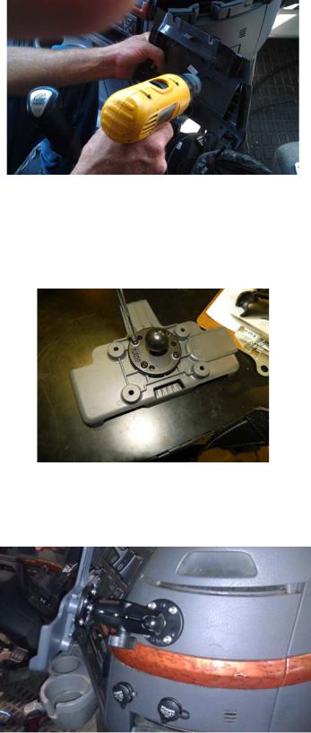
2.Drill 3/16" holes for the mounting bracket and backing plate using the backing plate as a template.
3.Attach the RAM mount ball joint to the dash using the supplied 8x32 screws, lock washers, and backing plate. This hardware is included with the RAM mount kit.
4.Attach the other RAM mount ball-joint to the holster using supplied screws and lock washers. The supplied screws are 1/2" long. DO NOT use screws that are too long or they will protrude through the holster.
5.Join the holster-side ball joint to the dash-side ball joint using the RAM mount arm. Loosen the arm lever and adjust the holster to the desired position and then tighten the arm lever to secure assembly into place. Be sure the arm is loosened prior to making adjustments and then retightened to secure in place.
80-JE026-1 Rev. B |
4-3 |
MAY CONTAIN U.S. AND INTERNATIONAL EXPORT CONTROLLED INFORMATION

Installing the Display |
Display Interface Unit Installation |
6.Snap the display into the holster by placing the bottom into the lower holster tabs and then push the top into the upper holster tab. It will snap into place.
7.Allow just enough display cable slack so the DIU can reach the driver steering wheel only. Ensure any excess cable is secured and does not interfere with the operation of the vehicle. Cable should not drape on the floor or cause a tripping hazard.
8.Add a tiewrap strain relief to the DIU cable where it comes out from under or behind the dash so it can’t be pulled out further.
WARNING
Excess cable can be a tripping hazard. Ensure cable is not draped where it will interfere with either the driver or passenger as they move within the cab.
4-4 |
80-JE026-1 Rev. B |
MAY CONTAIN U.S. AND INTERNATIONAL EXPORT CONTROLLED INFORMATION
5
Power I/O Cable Connection
The power I/O cable is used to connect to a truck’s Diagnostic Connector. It provides both power and the necessary vehicle data for the IVG system. There are multiple masterpacks depending on the truck type. See the individual Truck Installation Suggestion documents for more information. See Appendix G: Component Information for more information
Cable |
Trucks |
|
9-pin |
Most |
2006 and newer trucks |
6-pin |
Most |
2005 and older trucks |
9-pin adapter |
Late model Kenworth and Peterbilt trucks |
|
OBDII style |
2014 and newer Volvo/Mack trucks |
|
80-JE026-1 Rev. B |
5-1 |
MAY CONTAIN U.S. AND INTERNATIONAL EXPORT CONTROLLED INFORMATION
Connecting the Power I/O Cable |
Power I/O Cable Connection |
9-pin 500 Kbps |
2016 and newer model trucks with green diagnostic |
|
connectors |
Hino |
Late 2011 and newer Hino trucks |
The appropriate IVG kit/masterpack should have been ordered for your installation. If the power I/O Cable connector does not mate to the truck’s diagnostic connector, the Y portion of the power I/O Cable will need to be cut off and wires will need to be crimp spliced. See Chapter C: General Wiring and Installation Guidelines for instructions.
Connecting the Power I/O Cable
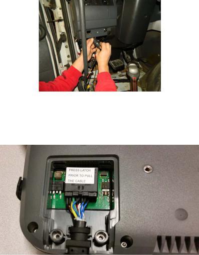
1.With the truck’s ignition OFF, remove and push back existing truck diagnostic connector. Check connector to verify it’s clean of debris and there are no bent pins.
2.Connect the power I/O cable connector to the truck’s diagnostic connector. Verify the outer ring is twisted and clicks into place so the ends do not become unconnected by accident. Verify by pull testing the connector.
3.Put the unused power I/O cable end where the truck’s diagnostic connector was located.
4.Route power cable to the IVG display location..
5.Remove torx10 screws from door panel on back side of IVG display and connect power cable to the IVG display. Ensure it latches solidly.
6.Replace door panel and secure any excess cable using tie-wraps.
5-2 |
80-JE026-1 Rev. B |
MAY CONTAIN U.S. AND INTERNATIONAL EXPORT CONTROLLED INFORMATION
6
Optional Accessories
Optional connections:
•PTO (Power Take-off)
•Trailer Tracks
•Panic Button
PTO (Power Take-off) Overview—Optional Connection
This option provides the ability to log the time the vehicle engine is used for operational idle purposes, such as when it is powering auxiliary devices using a pump or compressor.
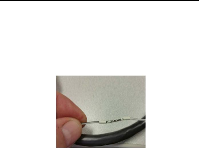
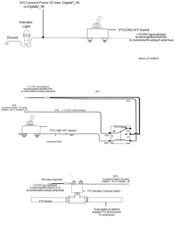
In order to log PTO time, the installation involves connecting one of the two PTO wires.
The loose white/black wire labeled PTO/DIGIN_1, in the power I/O cable is the PTO wire.
The IVG system detects an active PTO device when it sees 12 volts (active high) on this PTO/DIGIN_1 wire. A PTO switch that goes active to ground will require a relay for the 12 volt detection.
80-JE026-1 Rev. B |
6-1 |
MAY CONTAIN U.S. AND INTERNATIONAL EXPORT CONTROLLED INFORMATION
PTO Installation |
Optional Accessories |
PTO Installation
Use a multi-meter to determine which type of PTO circuit you are connecting to when engaging the PTO switch.
Wiring to Switched +12VDC Circuit
Wiring to Switched Ground Circuit
If you have a switched circuit that is activated to the ground to detect PTO time, a relay must be used.
Wiring to an Air Pressure Switch for Air-activated PTO
If the air pressure switch is not wired to 12 VDC, make sure to remove the ground wire and attach a fused wire from the IVG ignition source.
6-2 |
80-JE026-1 Rev. B |
MAY CONTAIN U.S. AND INTERNATIONAL EXPORT CONTROLLED INFORMATION
Optional Accessories |
PTO Data Input Verification Procedure |
PTO Data Input Verification Procedure
1.Start the vehicle.
2.Turn the PTO switch ON.
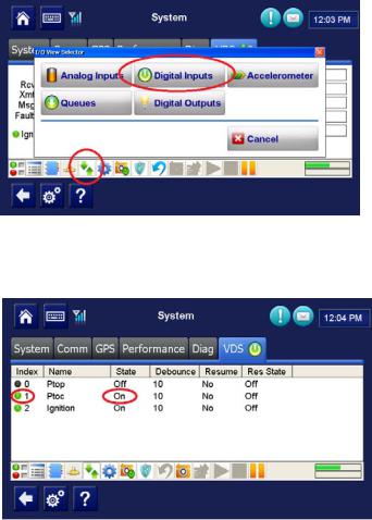
3.Navigate to the System VDS screen.
4.Tap the green up and down arrow button at bottom of the screen (circled below).
5.Verify the PTOC has a green dot under the Index column and shows “On” under the State column.
NOTE:
PTOC: PTO/DIGIN_1 in wire in the wire harness
If PTOC is not showing a green dot or "On," check the PTO wire connections.
6.Turn off PTO device. The green dot and state will change (i.e., to a black dot and “Off”).
7.At this point, the PTO wire installation verification is complete.
8.Verify through the Performance Monitoring screens that the PTO application is recording correctly.
80-JE026-1 Rev. B |
6-3 |
MAY CONTAIN U.S. AND INTERNATIONAL EXPORT CONTROLLED INFORMATION
Trailer Tracks Installation (placeholder) |
Optional Accessories |
9.Start the vehicle.
10.Turn the PTO device to ON.
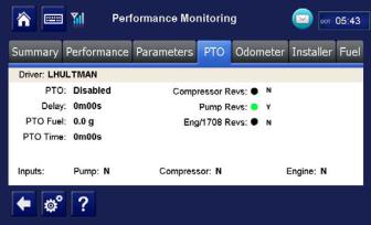
11.Navigate to the PTO screen. Tap the Performance Monitoring button, then tap the PTO tab.
Note: If the Performance Monitoring button is grayed out, Performance Monitoring is not enabled. Call your company dispatch to have this application enabled. Performance Monitoring parameters must be sent to the unit as well.
12.Verify that PTO is Enabled and the Compressor or Pump displays a Y according to what is active.
13.You should see the green indicator light according to what is active.
14.Check that the PTO Time field is incrementing. Is this field incrementing?
Note: In order for PTO time to be recorded in Performance Monitoring, RPM must be >0, speed <20 mph, and the PTO time delay (customer configured) must be reached.
•If yes, PTO verification is complete.
•If no, check the wire connections.
15.Turn off PTO device. PTO time should now stop incrementing.
Trailer Tracks Installation (placeholder)
Trailer Tracks Verification (placeholder)
Panic Button Installation (placeholder)
6-4 |
80-JE026-1 Rev. B |
MAY CONTAIN U.S. AND INTERNATIONAL EXPORT CONTROLLED INFORMATION
Loading...