

Page 1
CP TD1
Reference Manual
Page 2

CP TD1 Reference Manual V 1.44
Article Number: VESD0606 Manual Version: CPC100TD1.AE.6
© OMICRON electronics 2012. All rights reserved.
This manual is a publication of OMICRON electronics GmbH.
All rights including translation reserved. Reproduction of any kind, for example, photocopying,
microfilming, optical character recognition and/or storage in electronic data processing systems,
requires the explicit consent of OMICRON electronics. Reprinting, wholly or in part, is not permitted.
The product information, specifications, and technical data embodied in this manual represent the
technical status at the time of writing and are subject to change without prior notice.
We have done our best to ensure that the information given in this manual is useful, accurate and
entirely reliable. However, OMICRON electronics does not assume responsibility for any inaccuracies
which may be present.
The user is responsible for every application that makes use of an OMICRON product.
OMICRON electronics translates this manual from the source language English into a number of other
languages. Any translation of this manual is done for local requirements, and in the event of a dispute
between the English and a non-English version, the English version of this manual shall govern.
2
Page 3

Contents
Contents
Using this Manual . . . . . . . . . . . . . . . . . . . . . . . . . . . . . . . . . . . . . . . . . . . . . .7
Safety Rules . . . . . . . . . . . . . . . . . . . . . . . . . . . . . . . . . . . . . . . . . . . . . . . . . . .9
1 Introduction . . . . . . . . . . . . . . . . . . . . . . . . . . . . . . . . . . . . . . . . . . . . . . . . . .15
1.1 Designated Use . . . . . . . . . . . . . . . . . . . . . . . . . . . . . . . . . . . . . . . . . . . . . . . . . 15
1.2 Functional Components of the CPC 100 and CP TD1. . . . . . . . . . . . . . . . . . . . 16
1.3 Functional Components of the CP TD1 . . . . . . . . . . . . . . . . . . . . . . . . . . . . . . . 18
1.3.1 Grounding Terminal and Booster Input. . . . . . . . . . . . . . . . . . . . . . . . . . . . . . . 18
1.3.2 Serial Interface Connector and Measuring Inputs . . . . . . . . . . . . . . . . . . . . . . 18
1.3.3 High-Voltage Connector . . . . . . . . . . . . . . . . . . . . . . . . . . . . . . . . . . . . . . . . . . 19
2 Operation . . . . . . . . . . . . . . . . . . . . . . . . . . . . . . . . . . . . . . . . . . . . . . . . . . . .21
2.1 Measurement Setup . . . . . . . . . . . . . . . . . . . . . . . . . . . . . . . . . . . . . . . . . . . . . 21
2.1.1 Setup of Devices with Trolley . . . . . . . . . . . . . . . . . . . . . . . . . . . . . . . . . . . . . . 21
2.1.2 Setup of Devices without Trolley . . . . . . . . . . . . . . . . . . . . . . . . . . . . . . . . . . . 21
2.2 CP TD1 Connected to a Test Object . . . . . . . . . . . . . . . . . . . . . . . . . . . . . . . . . 22
2.3 CP TD1 Connected to CP CAL1 . . . . . . . . . . . . . . . . . . . . . . . . . . . . . . . . . . . . 23
2.4 Calibrating the CP TD1 Using a Reference Capacitor. . . . . . . . . . . . . . . . . . . . 23
2.4.1 Calibration Tips. . . . . . . . . . . . . . . . . . . . . . . . . . . . . . . . . . . . . . . . . . . . . . . . . 24
3 Test Cards . . . . . . . . . . . . . . . . . . . . . . . . . . . . . . . . . . . . . . . . . . . . . . . . . . .25
3.1 TanDelta Test Card - Main Page (1/2) . . . . . . . . . . . . . . . . . . . . . . . . . . . . . . . 25
3.2 TanDelta Test Card - Main Page (2/2) . . . . . . . . . . . . . . . . . . . . . . . . . . . . . . . 28
3.3 TanDelta Test Card - Settings Page (1/2) . . . . . . . . . . . . . . . . . . . . . . . . . . . . . 29
3.4 TanDelta Test Card - Settings Page (2/2) . . . . . . . . . . . . . . . . . . . . . . . . . . . . . 30
3.5 Templates . . . . . . . . . . . . . . . . . . . . . . . . . . . . . . . . . . . . . . . . . . . . . . . . . . . . . 31
4 Application . . . . . . . . . . . . . . . . . . . . . . . . . . . . . . . . . . . . . . . . . . . . . . . . . . .33
4.1 Preparations in Substation. . . . . . . . . . . . . . . . . . . . . . . . . . . . . . . . . . . . . . . . . 33
4.2 Connection. . . . . . . . . . . . . . . . . . . . . . . . . . . . . . . . . . . . . . . . . . . . . . . . . . . . . 33
4.3 Measurement. . . . . . . . . . . . . . . . . . . . . . . . . . . . . . . . . . . . . . . . . . . . . . . . . . . 35
4.4 Disconnection . . . . . . . . . . . . . . . . . . . . . . . . . . . . . . . . . . . . . . . . . . . . . . . . . . 36
5 Capacitance and Dissipation Factor Measurement . . . . . . . . . . . . . . . . . .39
5.1 Theory . . . . . . . . . . . . . . . . . . . . . . . . . . . . . . . . . . . . . . . . . . . . . . . . . . . . . . . . 39
3
Page 4

CP TD1 Reference Manual V 1.44
5.2 Measurement of Capacitance and Dissipation Factor / Power Factor. . . . . . . . 54
5.3 "UST" and "GST" Measurements Using the Guard Technology . . . . . . . . . . . . 58
5.4 References . . . . . . . . . . . . . . . . . . . . . . . . . . . . . . . . . . . . . . . . . . . . . . . . . . . . 63
6 Power Transformers . . . . . . . . . . . . . . . . . . . . . . . . . . . . . . . . . . . . . . . . . . .65
6.1 Introduction . . . . . . . . . . . . . . . . . . . . . . . . . . . . . . . . . . . . . . . . . . . . . . . . . . . . 65
6.2 Capacitance and DF Measurement of Transformer Windings. . . . . . . . . . . . . . 70
6.2.1 Three-Winding Transformer . . . . . . . . . . . . . . . . . . . . . . . . . . . . . . . . . . . . . . . 72
6.2.2 Two-Winding Transformer . . . . . . . . . . . . . . . . . . . . . . . . . . . . . . . . . . . . . . . . 85
6.2.3 Auto-Transformer . . . . . . . . . . . . . . . . . . . . . . . . . . . . . . . . . . . . . . . . . . . . . . . 87
6.2.4 Reactors . . . . . . . . . . . . . . . . . . . . . . . . . . . . . . . . . . . . . . . . . . . . . . . . . . . . . . 88
6.3 Transformer High-Voltage Bushing Tests . . . . . . . . . . . . . . . . . . . . . . . . . . . . . 88
6.4 Interpretation of Measurement Results . . . . . . . . . . . . . . . . . . . . . . . . . . . . . . . 88
6.4.1 Dissipation Factor Measurement . . . . . . . . . . . . . . . . . . . . . . . . . . . . . . . . . . . 88
6.4.2 Capacitance Measurement. . . . . . . . . . . . . . . . . . . . . . . . . . . . . . . . . . . . . . . . 89
6.5 References . . . . . . . . . . . . . . . . . . . . . . . . . . . . . . . . . . . . . . . . . . . . . . . . . . . . 89
7 Capacitance and DF Measurement on High-Voltage Bushings. . . . . . . . .91
7.1 Introduction . . . . . . . . . . . . . . . . . . . . . . . . . . . . . . . . . . . . . . . . . . . . . . . . . . . . 91
7.2 Types of Bushings . . . . . . . . . . . . . . . . . . . . . . . . . . . . . . . . . . . . . . . . . . . . . . . 91
7.3 Bushing Troubles. . . . . . . . . . . . . . . . . . . . . . . . . . . . . . . . . . . . . . . . . . . . . . . . 94
7.4 Capacitance and DF Measurement on High-Voltage Bushings. . . . . . . . . . . . . 96
7.5 Ungrounded Specimen Test (UST) . . . . . . . . . . . . . . . . . . . . . . . . . . . . . . . . . . 97
7.6 Grounded Specimen Test (GST) . . . . . . . . . . . . . . . . . . . . . . . . . . . . . . . . . . . . 99
7.7 Hot Collar Test. . . . . . . . . . . . . . . . . . . . . . . . . . . . . . . . . . . . . . . . . . . . . . . . . . 99
7.8 Interpretation of Measurement Results . . . . . . . . . . . . . . . . . . . . . . . . . . . . . . 104
7.9 References . . . . . . . . . . . . . . . . . . . . . . . . . . . . . . . . . . . . . . . . . . . . . . . . . . . 107
8 Capacitance and DF Measurement of Generators and Motors . . . . . . . .109
9 Capacitance and DF Measurement of Circuit Breakers . . . . . . . . . . . . . .111
9.1 Introduction . . . . . . . . . . . . . . . . . . . . . . . . . . . . . . . . . . . . . . . . . . . . . . . . . . . 111
9.2 Oil Circuit Breakers (Dead Tank). . . . . . . . . . . . . . . . . . . . . . . . . . . . . . . . . . . 111
9.3 Oil Poor Circuit Breakers (Live Tank) . . . . . . . . . . . . . . . . . . . . . . . . . . . . . . . 112
9.4 SF6 Circuit Breakers (Dead Tank with Bushings) . . . . . . . . . . . . . . . . . . . . . . 112
9.5 Vacuum Circuit Breakers . . . . . . . . . . . . . . . . . . . . . . . . . . . . . . . . . . . . . . . . . 112
9.6 Air Magnetic Circuit Breakers . . . . . . . . . . . . . . . . . . . . . . . . . . . . . . . . . . . . . 113
9.7 Oil Circuit Reclosers . . . . . . . . . . . . . . . . . . . . . . . . . . . . . . . . . . . . . . . . . . . . 113
4
Page 5

Contents
10 Capacitance and DF Measurement of Overvoltage Arresters . . . . . . . . .115
11 Technical Data . . . . . . . . . . . . . . . . . . . . . . . . . . . . . . . . . . . . . . . . . . . . . . .119
11.1 Technical Data of the CP TD1 in Combination with the CPC 100 . . . . . . . . . . 119
11.1.1 High-Voltage Output . . . . . . . . . . . . . . . . . . . . . . . . . . . . . . . . . . . . . . . . . . . . 119
11.1.2 Measurements . . . . . . . . . . . . . . . . . . . . . . . . . . . . . . . . . . . . . . . . . . . . . . . . 119
11.2 Environmental Conditions . . . . . . . . . . . . . . . . . . . . . . . . . . . . . . . . . . . . . . . . 123
11.3 CE Conformity and Safety Standards . . . . . . . . . . . . . . . . . . . . . . . . . . . . . . . 124
11.4 Cleaning. . . . . . . . . . . . . . . . . . . . . . . . . . . . . . . . . . . . . . . . . . . . . . . . . . . . . . 124
11.5 Accessories . . . . . . . . . . . . . . . . . . . . . . . . . . . . . . . . . . . . . . . . . . . . . . . . . . . 125
11.5.1 Cables and Clamps . . . . . . . . . . . . . . . . . . . . . . . . . . . . . . . . . . . . . . . . . . . . 125
11.5.2 Optional Accessories . . . . . . . . . . . . . . . . . . . . . . . . . . . . . . . . . . . . . . . . . . . 126
11.6 Ordering Information . . . . . . . . . . . . . . . . . . . . . . . . . . . . . . . . . . . . . . . . . . . . 127
12 Appendix. . . . . . . . . . . . . . . . . . . . . . . . . . . . . . . . . . . . . . . . . . . . . . . . . . . .129
12.1 Parallel and Serial Equivalent Circuit Diagrams . . . . . . . . . . . . . . . . . . . . . . . 129
12.2 Negative DF Measurements . . . . . . . . . . . . . . . . . . . . . . . . . . . . . . . . . . . . . . 130
12.3 Two- and Three-Winding Transformer Tests (IEEE C57.12.90) . . . . . . . . . . . 132
12.4 Limits for Test Voltages for C2 Testing on Bushings. . . . . . . . . . . . . . . . . . . . 133
12.5 C2 Measurement on High-Voltage Bushings. . . . . . . . . . . . . . . . . . . . . . . . . . 133
12.5.1 Abstract. . . . . . . . . . . . . . . . . . . . . . . . . . . . . . . . . . . . . . . . . . . . . . . . . . . . . . 133
12.5.2 Introduction . . . . . . . . . . . . . . . . . . . . . . . . . . . . . . . . . . . . . . . . . . . . . . . . . . . 134
12.5.3 Design/Construction of C1 and C2 Capacitance in Condenser Bushings . . . 134
12.5.4 Factors Affecting C1, C2 Capacitance and Power Factor Measurements . . . 136
12.5.5 Conclusions . . . . . . . . . . . . . . . . . . . . . . . . . . . . . . . . . . . . . . . . . . . . . . . . . . 140
12.5.6 Biography . . . . . . . . . . . . . . . . . . . . . . . . . . . . . . . . . . . . . . . . . . . . . . . . . . . . 141
12.5.7 References . . . . . . . . . . . . . . . . . . . . . . . . . . . . . . . . . . . . . . . . . . . . . . . . . . . 141
12.6 DF Limits of RBP Bushings (Micafil AG) . . . . . . . . . . . . . . . . . . . . . . . . . . . . . 142
12.7 DF Limits of Bushings (B) . . . . . . . . . . . . . . . . . . . . . . . . . . . . . . . . . . . . . . . . 143
12.8 DF Limits of Bushings (C) . . . . . . . . . . . . . . . . . . . . . . . . . . . . . . . . . . . . . . . . 144
12.9 Transformer Diagnosis. . . . . . . . . . . . . . . . . . . . . . . . . . . . . . . . . . . . . . . . . . . 146
12.9.1 Introduction . . . . . . . . . . . . . . . . . . . . . . . . . . . . . . . . . . . . . . . . . . . . . . . . . . . 147
12.9.2 Methods of Analysis . . . . . . . . . . . . . . . . . . . . . . . . . . . . . . . . . . . . . . . . . . . . 149
12.9.3 Fault Localization . . . . . . . . . . . . . . . . . . . . . . . . . . . . . . . . . . . . . . . . . . . . . . 150
12.9.4 Winding Resistance Measurement and On-Load Tap Changer Test. . . . . . . 151
12.9.5 Four-Wire Connection for Transformer Winding Resistance Measurement. . 155
12.9.6 Safety Aspects . . . . . . . . . . . . . . . . . . . . . . . . . . . . . . . . . . . . . . . . . . . . . . . . 156
12.9.7 Delta-Connected Windings . . . . . . . . . . . . . . . . . . . . . . . . . . . . . . . . . . . . . . . 157
5
Page 6

CP TD1 Reference Manual V 1.44
12.9.8 Winding Resistance Measurement of a 100 MVA Transformer . . . . . . . . . . . 158
12.9.9 Dynamic Behavior of the Diverter Switch . . . . . . . . . . . . . . . . . . . . . . . . . . . . 162
12.9.10 Turns Ratio . . . . . . . . . . . . . . . . . . . . . . . . . . . . . . . . . . . . . . . . . . . . . . . . . . . 163
12.9.11 Excitation Current . . . . . . . . . . . . . . . . . . . . . . . . . . . . . . . . . . . . . . . . . . . . . . 165
12.9.12 Leakage Reactance . . . . . . . . . . . . . . . . . . . . . . . . . . . . . . . . . . . . . . . . . . . . 166
12.9.13 Capacitance and DF Measurement . . . . . . . . . . . . . . . . . . . . . . . . . . . . . . . . 169
12.9.14 DF Measurements on Transformer Windings . . . . . . . . . . . . . . . . . . . . . . . . . 174
12.9.15 Capacitance Measurements on Transformer Windings . . . . . . . . . . . . . . . . . 175
12.9.16 Capacitance and DF Measurements on Transformer Bushings. . . . . . . . . . . 175
12.9.17 Summary . . . . . . . . . . . . . . . . . . . . . . . . . . . . . . . . . . . . . . . . . . . . . . . . . . . . 179
12.10References . . . . . . . . . . . . . . . . . . . . . . . . . . . . . . . . . . . . . . . . . . . . . . . . . . . 180
12.11Temperature Correction Factors . . . . . . . . . . . . . . . . . . . . . . . . . . . . . . . . . . . 181
12.11.1 Transformers . . . . . . . . . . . . . . . . . . . . . . . . . . . . . . . . . . . . . . . . . . . . . . . . . 181
12.11.2 Bushings. . . . . . . . . . . . . . . . . . . . . . . . . . . . . . . . . . . . . . . . . . . . . . . . . . . . . 182
OMICRON Service Centers . . . . . . . . . . . . . . . . . . . . . . . . . . . . . . . . . . . . .185
Index . . . . . . . . . . . . . . . . . . . . . . . . . . . . . . . . . . . . . . . . . . . . . . . . . . . . . . 187
6
Page 7

Using this Manual
This User Manual provides information on how to use the CP TD1 safely,
properly and efficiently. The CP TD1 Reference Manual contains important
safety rules for working with the CP TD1 and gets you familiar with operating the
CP TD1. Following the instructions in this Reference Manual will help you to
prevent danger, repair costs and possible down time due to incorrect operation.
The CP TD1 Reference Manual always has to be available on the site where the
CP TD1 is used. It must be read and observed by all users of the CP TD1.
Reading the CP TD1 Reference Manual alone does not release you from the
duty of complying with all national and international safety regulations relevant
to working on power transformers.
Operator Qualifications and Safety Standards
Working on high-voltage assets can be extremely dangerous. Testing with the
CP TD1 must be carried out only by qualified, skilled and authorized personnel.
Before starting to work, clearly establish the responsibilities.
Preface
Personnel receiving training, instructions, directions, or education on the
CP TD1 must be under constant supervision of an experienced operator while
working with the equipment.
Testing with the CP TD1 must comply with the internal safety instructions as well
as additional relevant documents.
In addition, observe the following safety standards, if applicable:
• EN 50191 (VDE 0104) "Erection and Operation of Electrical Equipment"
• EN 50110-1 (VDE 0105 Part 100) "Operation of Electrical Installations"
• IEEE 510 "IEEE Recommended Practices for Safety in High-Voltage and
High-Power Testing"
7
Page 8
CP TD1 Reference Manual V 1.44
Symbols Used
In this manual, the following symbols indicate paragraphs with special safety
relevant meaning:
Symbol Description
General
Caution: Equipment damage or loss of data possible
Warning: Personal injury or death of the operating staff or
severe damage to objects possible
Always observe the five safety rules:
• Disconnect completely
• Secure from reconnection
• Verify that the installation is dead
• Carry out grounding and short-circuiting
• Provide protection against adjacent live parts
8
Page 9

Safety Rules
Before operating the CP TD1, read the following safety rules carefully. If you do
not understand some safety rules, contact OMICRON electronics before
proceeding.
Maintenance and repair of the CP TD1 is only permitted by qualified experts at
OMICRON electronics repair centers.
Operating the Measurement Setup
Only personnel qualified in electrical engineering and trained by OMICRON
electronics are authorized to operate the CP TD1. Before starting the work,
clearly establish the responsibilities.
Personnel receiving training, instructions, directions, or education on the
CP TD1 must be under constant supervision of an experienced operator while
working with the equipment.
Preface
The operator is responsible for the safety requirements during the whole test.
Warning: Do not enter the high-voltage area if the red warning light of the
CPC 100 is on since all outputs carry dangerous voltage or current!
Always obey the five safety rules and follow the detailed safety instructions in
the respective user manuals.
9
Page 10
CP TD1 Reference Manual V 1.44
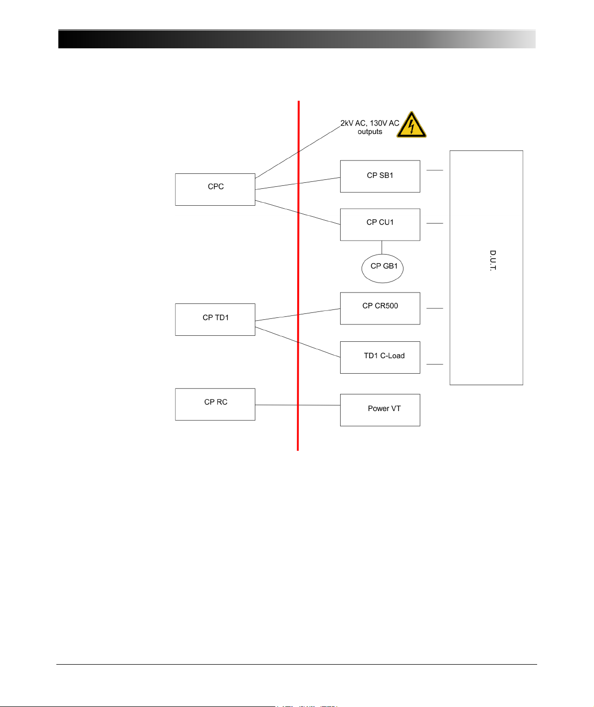
Safe area High-voltage area
Figure 1-1 Example for the separation of safe and high-voltage area using
10
different OMICRON electronics devices
Page 11

Preface
Before performing tests using high voltage, observe the following instructions:
• Do not use the test equipment without a good connection to substation
ground.
• Do not insert objects (for example screwdrivers, etc.) into any input/output
socket.
• Do not operate the CP TD1 under ambient conditions that exceed the
temperature and humidity limits listed in 11.2 "Environmental Conditions" on
page 123.
• Make sure to position the test equipment on dry, solid ground.
• Do not operate the CP TD1 in the presence of explosives, gas or vapors.
• Opening the CP TD1 invalidates all warranty claims.
• Do not use an extension cable on a cable reel to prevent an overheating of
the cord; run out the extension cord.
• If the CP TD1 does not seem to function properly, do not use it anymore.
Please call the OMICRON electronics technical support.
Handling Cables
• Always turn off the CP TD1 completely before you connect or disconnect any
cable (disconnect the CPC 100 from mains or press its Emergency Stop
button).
• The high-voltage cable must always be well attached and tightly connected
to both the CP TD1 and the test object. A loose or even falling off connector
at the test object carrying high-voltage is life-hazardous. Make sure the
connectors are clean and dry before connecting.
At the CP TD1, press the high-voltage cable’s plug to the connector tightly
and turn the screw cap until you feel a mechanical stop. If you notice a roughrunning of the screw-cap, clean the screw thread and use a lubricant
(vaseline recommended).
At the test object, insert the high-voltage cables’ plugs carefully until you feel
a "click" position. Now they are locked. Confirm this by trying to pull them out.
This should not be possible now.
Note: Tighten the plugs manually. Do not use any tools for that because that
can damage the plugs or connectors.
Insert the yellow banana plug (the high-voltage cable’s grounding) into the
respective plug socket.
11
Page 12
CP TD1 Reference Manual V 1.44
• Do not connect any cable to the test object without a visible grounding of the
test object.
• The high-voltage cable is double-shielded and therefore safe. However, the
last 50cm (20 inch) of this cable have no shield. Therefore, during a test
consider this cable a life wire and due to the high-voltage life-hazardous!
Warning: When the CPC 100 is switched on, consider this part of the cable
has to be in the high-voltage area due to a hazard of electric shock!
•Never remove any cables from the CP TD1 or the test object during a test.
• Keep clear from zones in which high voltages may occur. Set up a barrier or
establish similar adequate means.
• Both low-voltage measuring cables must always be well attached and tightly
connected to the CP TD1’s measuring inputs IN A and IN B.
Make sure to insert the red and blue marked cables into the corresponding
measuring inputs: IN A = red, IN B = blue.
Tighten the plugs by turning them until you feel a stop.
Note: Tighten the plugs manually. Do not use any tools for that because that
can damage the plugs or connectors.
Do not use any other cables than the ones supplied by OMICRON electronics.
Orderly Measures
The CP TD1 Reference Manual or alternatively the e-book in PDF format has
always to be available on site where the CP TD1 is being used. It must be read
and observed by all users of the CP TD1.
Warning: The CP TD1 may be used only as described in this Reference
Manual. Any other use is not in accordance with the regulations.
The manufacturer and/or distributor is not liable for damage resulting from
improper usage. The user alone assumes all responsibility and risk.
Following the instructions provided in this User Manual is also considered part
of being in accordance with the regulations.
12
Page 13

Preface
Disclaimer
If the equipment is used in a manner not specified by the manufacturer, the
protection provided by the equipment may be impaired.
Static Charges
Static charges on bushings or other apparatus such as transformer windings
may be induced by test potentials. While the voltage may not be significant
enough to do any damage, it can be a source for serious accidents due to falls
caused by reflex action.
High static charges may also be encountered at the bushing capacitance taps if
the covers are removed. Also, you should use safety grounds before handling.
Note: Always observe the five safety rules!
13
Page 14

CP TD1 Reference Manual V 1.44
14
Page 15

1 Introduction
1.1 Designated Use
The CP TD1 is an optionally available high-precision test system for on-site
insulation tests of high-voltage systems like power and measuring transformers,
circuit breakers, capacitors and isolators. With the add-on device CP TD1, the
CPC 100 increases its range of possible applications into high-voltage
measurements.
The internal switched mode power amplifier enables measuring at different
frequencies without interferences with the mains frequency. Automatic test
procedures reduce the testing time to a minimum. Test reports are generated
automatically.
The CP TD1 comes with its own test card named TanDelta (Tangent Delta),
which provides highly accurate measurements of the capacitance Cx and the
dissipation factor tanδ (DF) or power factor cos ϕ (PF), respectively.
Introduction
Both the dissipation factor and the power factor grant information about possible
losses in the insulation material, which are increasing with age and water
content. A change of Cx is a warning indicator for partial breakdowns between
the layers of a bushing or a capacitor.
Additionally, the CP TD1 measures the following quantities:
• Actual, apparent and reactive power
• Quality factor QF
• Inductance
• Impedance, phase angle
• Test voltage & current
The CP TD1 works as an add-on device to the CPC 100. Do not connect the
CP TD1 to any other device. Do not use the accessories for applications not
indicated in this user manual.
Any other use of the CP TD1 but the one mentioned above is considered
improper use, and will not only invalidate all customer warranty claims but also
exempt the manufacturer from its liability to recourse.
15
Page 16
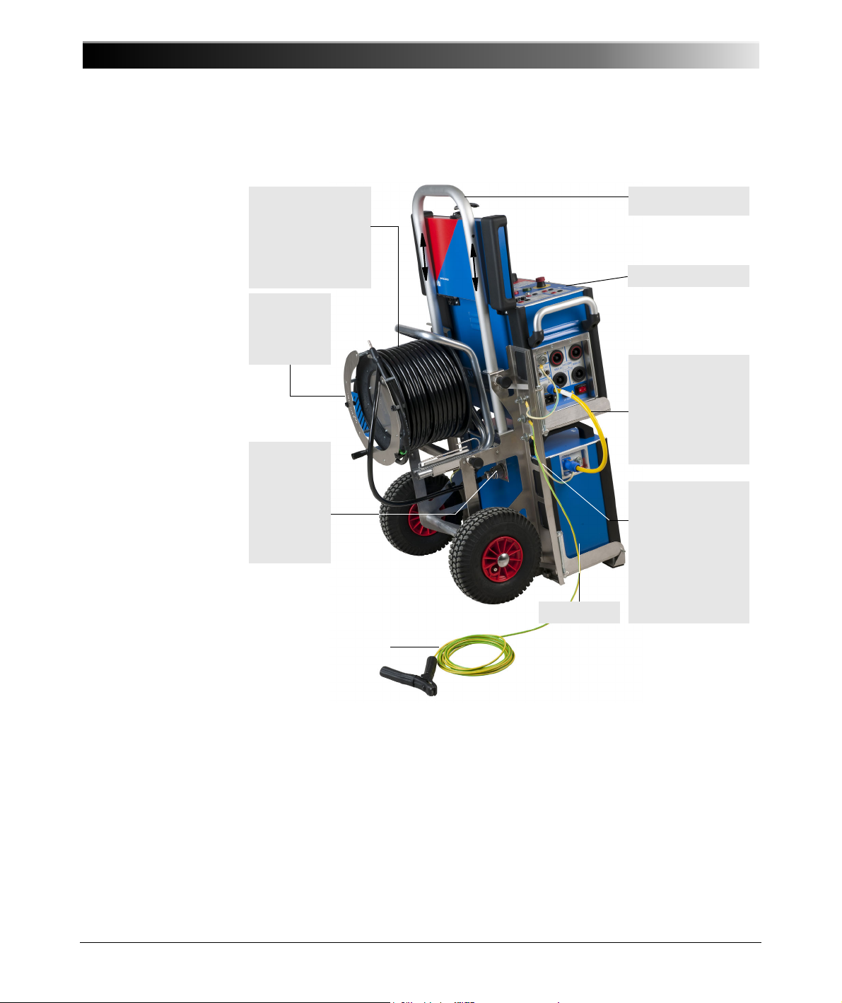
CP TD1 Reference Manual V 1.44
Cable drum with
double-shielded
output cable to feed
the high voltage to the
test object.
High-voltage
output with
attached
screw plug
and yellow
grounding
plug.
Equipment trolley
Booster cable
CPC 100
⇔ CP TD1
(short type). Via this
cable CPC 100 controls
the CP TD1 output
voltage.
CPC 100
CPC 100, CP TD1
and the equipment
trolley connected to
the trolley’s grounding
bar and led to earth.
Grounding cable min.
6mm².
CP TD1
Grounding terminal
Cable drum for
measuring
cables
1.2 Functional Components of the CPC 100 and CP TD1
16
Page 17
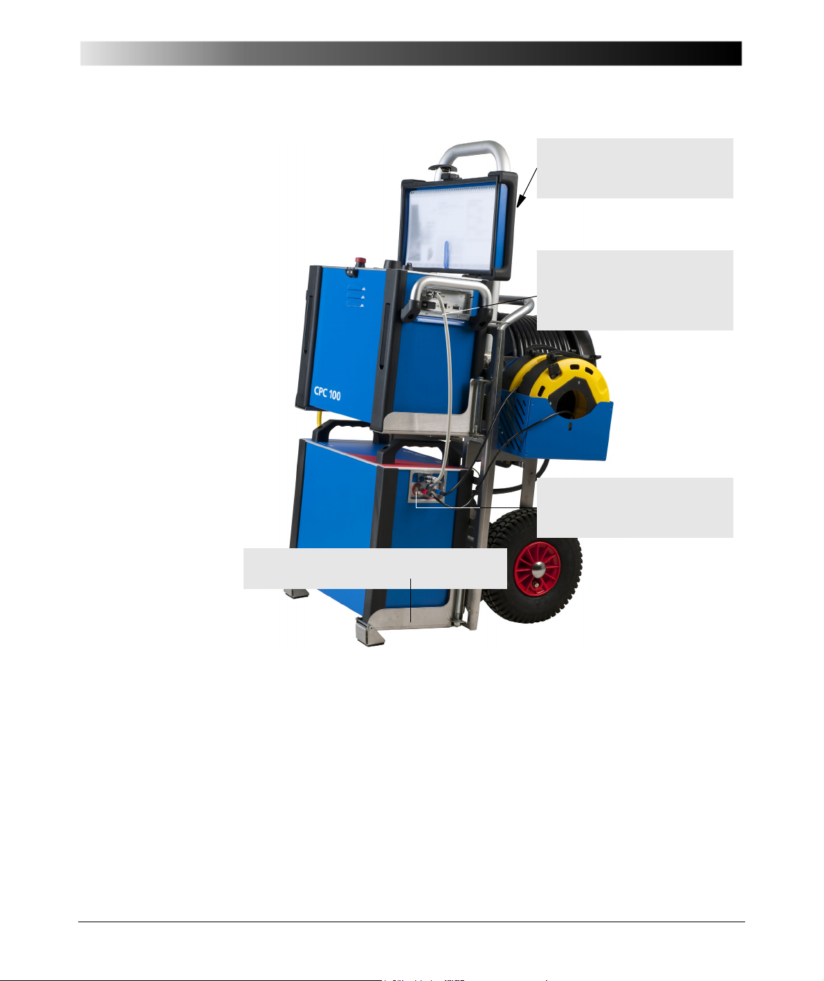
Introduction
CP TD1’s measuring inputs IN A and
IN B, connected to the cable drum for
the measuring cables.
Swivelling mounting brackets for the CPC 100 (top)
and CP TD1 (bottom).
To secure the CPC 100 while pulling
the trolley, a safety belt is available
(not shown).
Data cable CPC 100 ⇔ CP TD1
(short type). Via this data cable, the
CPC 100 software (test card
TanDelta) controls the CP TD1.
17
Page 18
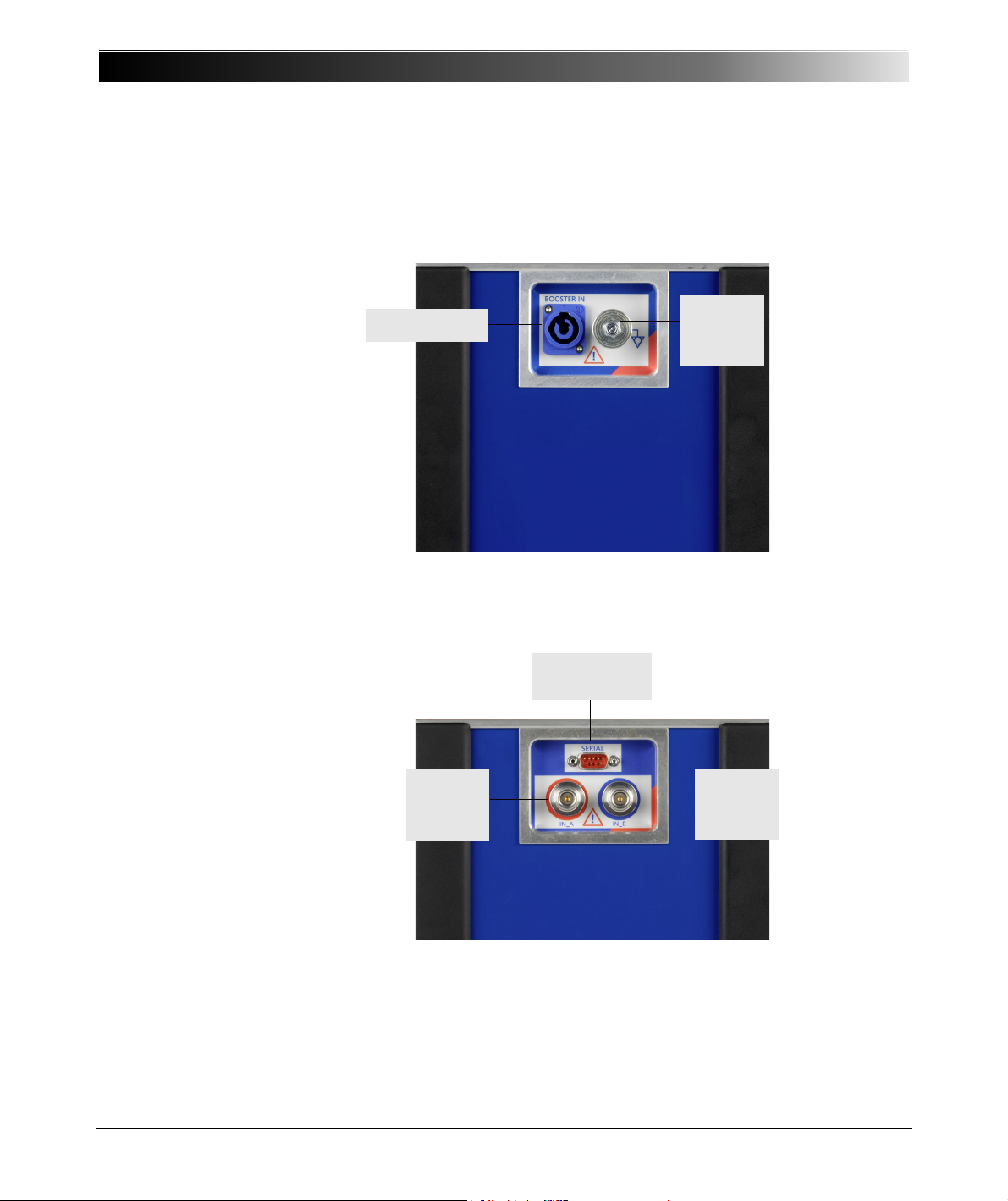
CP TD1 Reference Manual V 1.44
Booster Input
Grounding
terminal
IN_A
measuring
input
IN_B
measuring
input
Serial interface
connector
1.3 Functional Components of the CP TD1
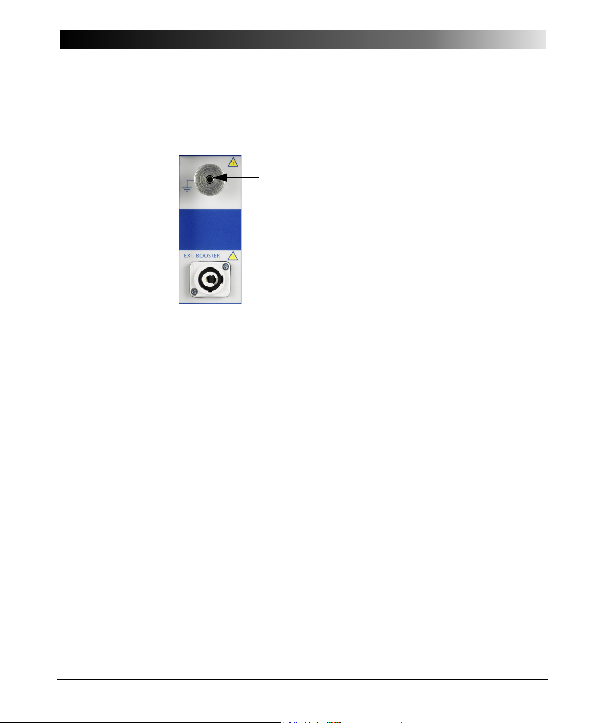
1.3.1 Grounding Terminal and Booster Input
1.3.2 Serial Interface Connector and Measuring Inputs
Figure 1-2 Grounding terminal and booster input of the CP TD1
Figure 1-3 Serial interface and measuring inputs of the CP TD1
18
Page 19
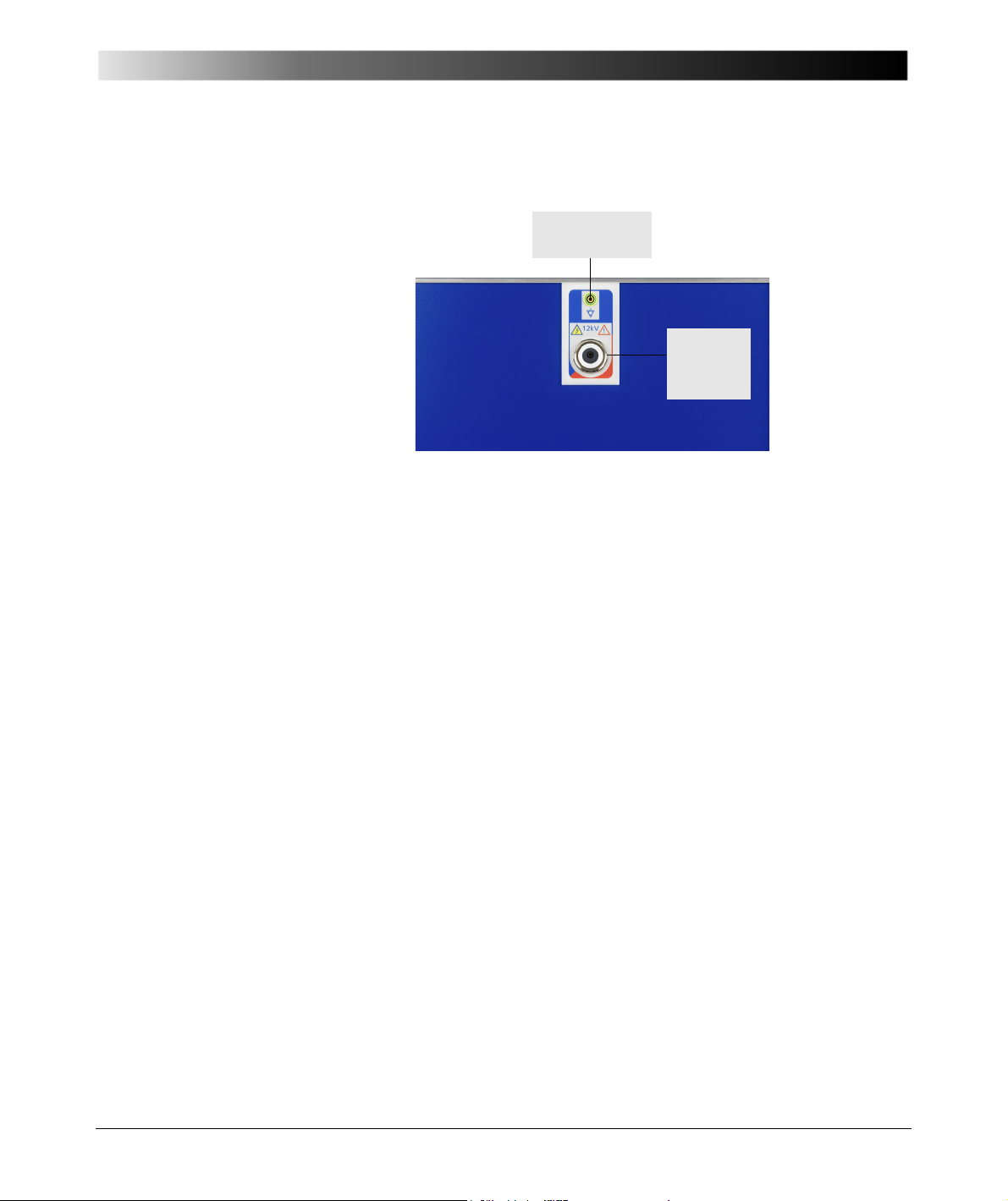
1.3.3 High-Voltage Connector
Highvoltage
connector
Grounding
terminal
Figure 1-4 High-voltage connector of the CP TD1
Introduction
19
Page 20

CP TD1 Reference Manual V 1.44
20
Page 21

2 Operation
2.1 Measurement Setup
2.1.1 Setup of Devices with Trolley
The equipment trolley holds the CPC 100, CP TD1 and all required cables. The
trolley is equipped with a grounding bar with three knurled screws to ensure a
solid connection to the grounding terminals of all devices.
2.1.2 Setup of Devices without Trolley
If the CPC 100 and CP TD1 are to be operated without trolley, place them on
their transport cases and connect them with the long type data cable
CPC 100 ⇔ CP TD1 (3m) and the long-type booster cable CPC 100 ⇔ CP TD1
(3m). Each device has to be grounded separately with a 6m grounding cable of
at least 6mm
2
.
Operation
21
Page 22
CP TD1 Reference Manual V 1.44
CP TD1
CPC 100
IN
Ix
Measurement
PE
12 kV
IN A
IN B
Power transformer
Grounding terminal
Booster Serial
Safe area
HV area
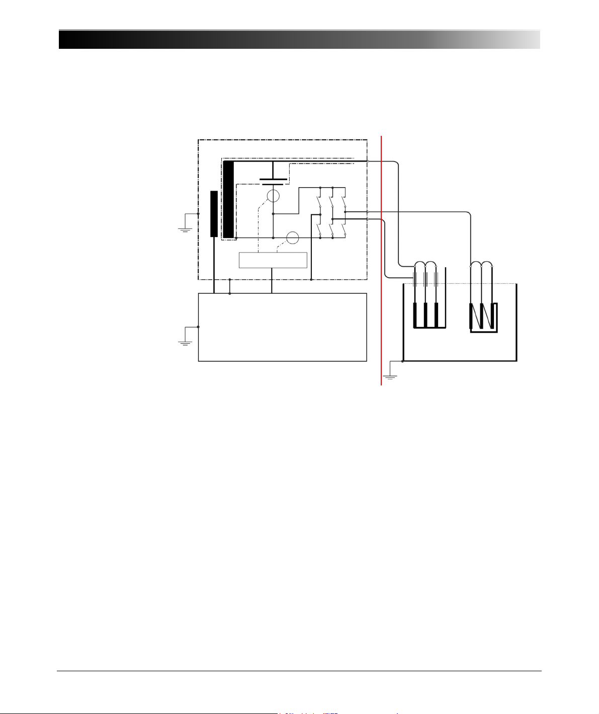
2.2 CP TD1 Connected to a Test Object
22
Page 23
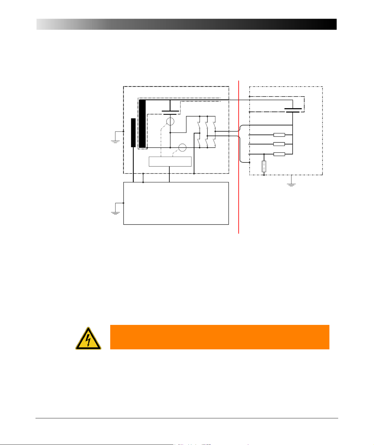
2.3 CP TD1 Connected to CP CAL1
CP TD1
CPC 100
Ix
Measurement
PE
Booster
12 kV
IN A
IN B
Grounding terminal
CP CAL1
Serial
C1
C2
C3
Safe area
HV area
Operation
Measuring mode = UST-A
When using the CP CAL1 for calibration, we recommend to take C1 as
reference and to select the calibration frequency in a range between
50 ... 200Hz.
2.4 Calibrating the CP TD1 Using a Reference Capacitor
Warning: For using the CP CAL1, make sure to apply the same procedure as
described in this Reference Manual.
By connecting a reference capacitor (e.g., optional device CP CAL1) with known
values of capacity Cref and dissipation factor DFref, in mode UST-A the values
Cx and DFx can be measured and then compared to the known reference
values.
23
Page 24

CP TD1 Reference Manual V 1.44
If you experience substantial deviations, re-calibrate the CP TD1:
• Cx = C ref / Cmeas and
•DF/PF+=DFref-DFmeas
as described in 3.3 on page 29.
A re-calibration of the CP TD1 is also shown in the test report (.xml file).
Note: If you change the factory-made calibration, the responsibility for the
accuracy of the CP TD1 will be in your hands.
2.4.1 Calibration Tips
• For calibration set the averaging factor to maximum and the filter bandwidth
to ± 5Hz (refer to 3.1 ”TanDelta Test Card - Main Page (1/2)” on page 25).
• To reset to the factory settings, select "DF/PF+" to 0.0 ppm and "Cx" to 1.000
(refer to 3.3 ”TanDelta Test Card - Settings Page (1/2)” on page 29).
24
Page 25
3Test Cards
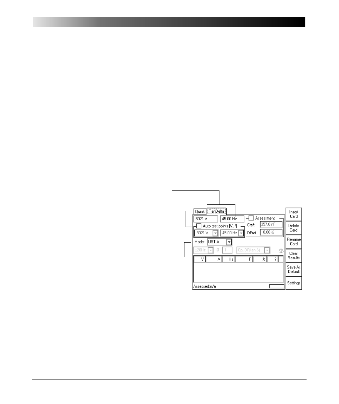
Select for automatic
measurement, clear for manual
measurement.
*)
.
Selecting enables the list boxes.
Select "Assessment" to automatically assess the test, clear for no assessment.
Enter the nominal values in the entry fields (here "Cref" and "DF ref"; availability
and naming depend on the measuring mode). These values serve as reference
for the assessment. Their tolerance range can be set on the Settings Page (refer
to page 29).
A measurement is rated as ’OK’ if both values are within their tolerance range.
The assessment is displayed in the test point tables’s column "?"
Note: While a test is running, new nominal values can already be entered.
Test voltage and frequency.
Selecting a measuring mode
and pressing the handwheel
displays an image that shows
the according arrangement of
the internal measurement
switch-matrix.
**)
Results table.
Also refer to page 30.
*)
3.1 TanDelta Test Card - Main Page (1/2)
The test card TanDelta can be accessed from C T , V T, T RANSFORMER and
O
THERS.
Test Cards
"Auto test points" cleared = manual measurement: Applies the set test
voltage and frequency to the CP TD1’s output. When the measurement is
finished, its results are displayed in the results table.
25
Page 26

CP TD1 Reference Manual V 1.44
"Auto test points" selected = automatic measurement: Enables the output
of a series of test points, e.g., combining a series of voltage values with one fixed
frequency value creates a voltage ramp. Combining a series of frequency values
with one fixed voltage value creates a frequency ramp. Furthermore, a
combination of both is possible.
– Set a test voltage and frequency of your choice, and press A
DD TO AUTO.
The values are entered into the list boxes.
– Set a second test voltage and/or frequency, and again press A
A
UTO. The value(s) is/are appended to the list.
DD TO
– Repeat this procedure as often as you need.
Note: You cannot enter the same value twice. Double entries are rejected. If you
need identical test points for an increasing and a decreasing voltage ramp, set
values very close to each other, e.g., 2000V and 2001V.
The CP TD1 then puts out the specified list of values as follows:
1. All voltages are issued in the exact order they were entered using the first
frequency value of the list.
2. All voltages are issued once more in the exact order they were entered using
the second frequency value of the list (if any).
3. ... and so forth.
Each combination is one individual measurement, and its result is displayed in
the results table with an individual line.
To delete an entry from a list box, place the cursor on the value and press
D
ELETE VALUE. Do delete all values from both list boxes, place the cursor on
"Auto test points (V, f)" and press D
ELETE LIST.
During the measurement, the list boxes display the current output values.
26
Page 27
Test Cards
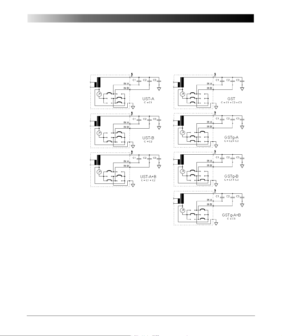
**)
Measuring modes and their according arrangements of the
internal switch-matrix in the CP TD1.
The switch-matrix determines what capacities are actually measured.
27
Page 28
CP TD1 Reference Manual V 1.44
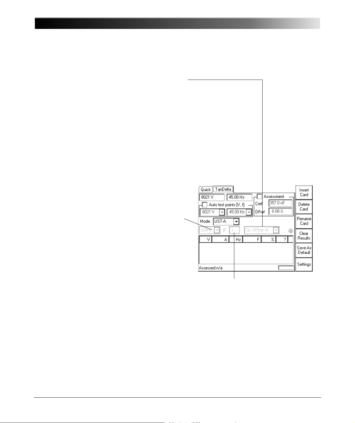
The averaging factor
determines the number of
measurements. A factor of 3
means: the CP TD1 carries out 3
measurements whose results
are then averaged. The higher
the factor, the more accurate the
measurement but the longer the
measuring time.
Filter bandwidth of measurement.
Note: If the test frequency equals the default
frequency (as set at O
PTIONS | DEVICE SETUP),
the filter bandwidth is always ± 5Hz, regardless of the
set value. This even applies if the option "use default
frequency of xx.xx Hz" is not specifically selected.
± 5Hz means that interferences at frequencies with
an offset of
≥ ± 5Hz from the measuring frequency
will not affect the results.
The smaller the filter bandwidth, the longer the
measuring time.
Compound measurement setting.
Cp, DF (tanδ) = parallel capacitance & dissipation factor
Cp, PF (cosϕ) = parallel capacitance & power factor
Cp, Ptest = parallel capacitance & power
Cp, P@10kV = parallel capacitance & power
linearly interpolated to 10 kV test voltage
Qtest, Stest = reactive & apparent power
Z = impedance with phase angle
Cp, Rp = parallel capacitance & parallel resistance
Ls, Rs = serial inductance & serial resistance
Cp, Q = parallel capacitance & quality factor
Ls, Q = series inductance & quality factor
3.2 TanDelta Test Card - Main Page (2/2)
28
Page 29
3.3 TanDelta Test Card - Settings Page (1/2)
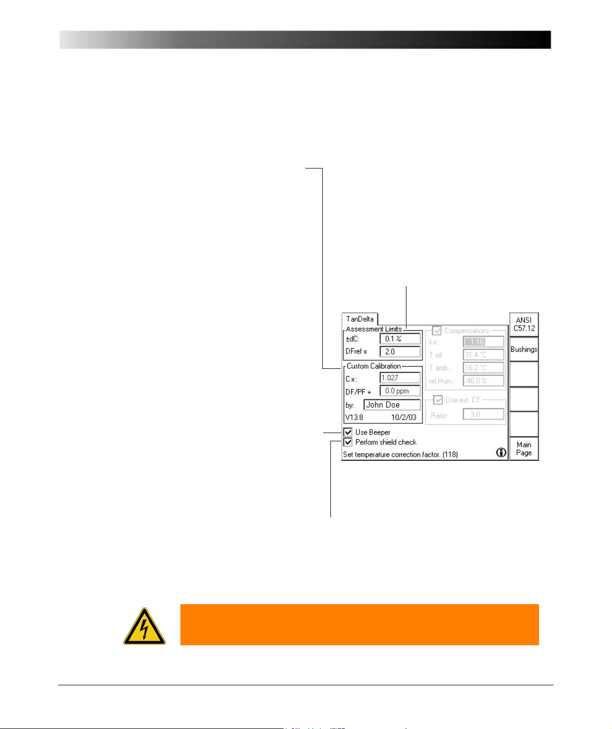
At "Assessment Limits", set the tolerance of
the Main Page’s nominal values for the
assessment.
For the capacitance, the tolerance is
entered in percent, for the dissipation factor
it’s a multiplier.
Note: Availability and naming of the entry
fields depend on the measuring mode, e.g.,
DF and PF are the same entry field.
The CP TD1 leaves
OMICRON factory-calibrated.
If a component needs to be
exchanged by a spare part, the
CP TD1 must be re-calibrated.
To re-calibrate, set the focus
onto the test card tab
designation TanDelta and
press E
DIT CALIB to enable
the entry fields:
• Cx = correction factor for
Cmeas (multiplier)
• DF/PF + = corrective value
added to dissipation or
power factor (can be + or -).
Note: You must enter your
name and press U
PDATE
C
ALIB. to complete the re-
calibration.
If selected, the beeper sounds
during the entire test to signal
the output of hazardous high
voltages. If cleared, the beeper
sounds at the beginning and
the end of the test only.
If selected, the CPC 100 checks whether the shield of the high-voltage cable is
connected. For some large inductive loads, the CPC 100 can accidentally report
shield check error even when the shield is connected. If this is the case, it makes
sense to clear the check box.
The TanDelta Settings page allows for the setting of additional measurement
options. To open it, press the S
ETTINGS button on the TanDelta Main Page.
Test Cards
Warning: Never operate the CP TD1 with unconnected shield of the high-
voltage cable. If the "Perform shield check" check box is cleared, make sure
that the shield is connected before operating the CP TD1.
29
Page 30
CP TD1 Reference Manual V 1.44
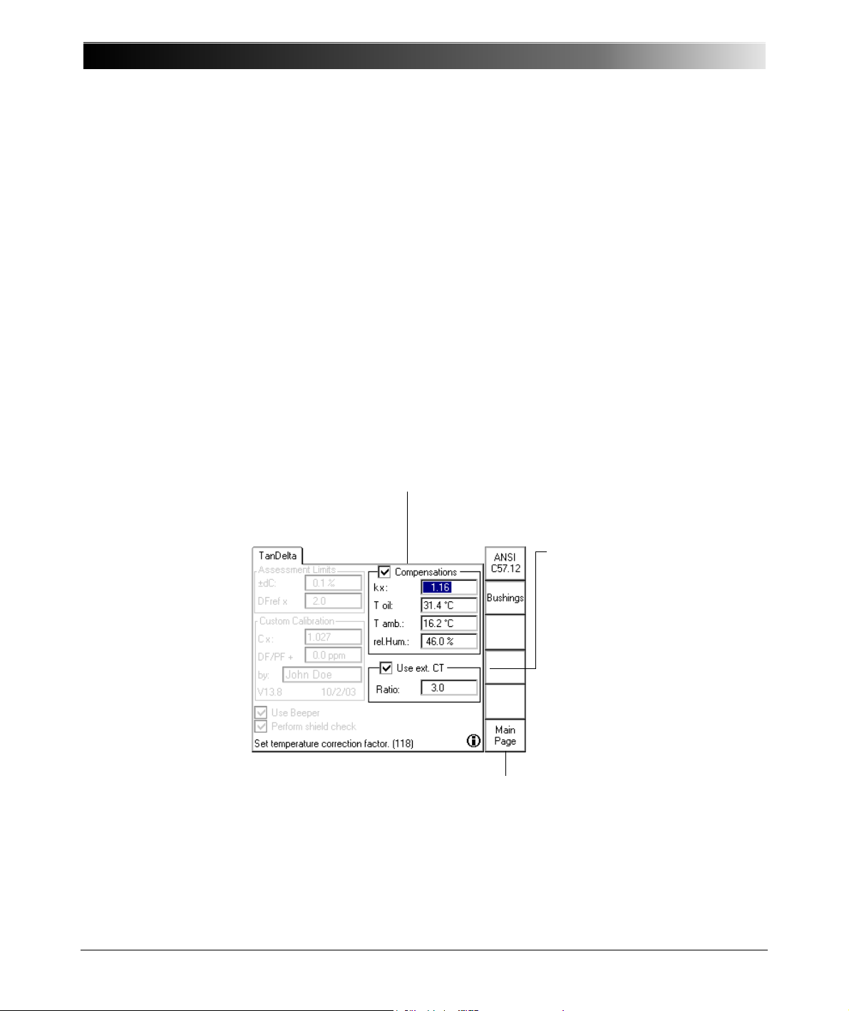
Selecting "Compensations" converts the actually measured dissipation or
power factor to normalized values corresponding to an ambient temperature of
20°C. In doing so, the values entered at "Compensations" represent the existing
ambient condition.
– Enter oil temperature, ambient temperature (at bushing) and relative
humidity first.
– Then place the cursor on "k".
The medium the measurement takes place in, oil or air, determines the k-factor.
– ANSI C57.12
The oil temperature is the determining medium for the k-factor.
– Bushings
The air temperature at the respective bushing is the determining medium for
the k-factor. B
USHINGS provides three bushing types to select from: RBP
(Resin Bonded Paper), RIP (Resin Impregnated Paper) and OIP (Oil
Impregnated Paper). The k-factor changes accordingly.
Select if you use an external
CT.
The entered ratio is used to
calculate the measured current
accordingly.
Note: "Use ext. CT" can only
be selected if there are no
measurement results yet.
Returns to TanDelta’s Main Page
3.4 TanDelta Test Card - Settings Page (2/2)
30
Page 31

3.5 Templates
The test procedures for designated applications are controlled by templates
available on the CPC Toolsets shipped with your CP TD1 or on the
CPC 100 Start Page.
The templates are pairs of XML documents and Microsoft Excel templates
designed by OMICRON electronics for designated applications. The XML
templates are predefined test procedures, often with comments, that run on the
CPC 100 and guide your through the test. Once completed, the XML file is
saved, downloaded to the PC and then loaded into the corresponding Microsoft
Excel template. There the results are post-processed and a final test report is
generated. The template pairs facilitate and speed testing with the CP TD1 and
the evaluation of results.
To perform a test using a template, open the template for your application and
run the test procedure according to the template.
Test Cards
31
Page 32

CP TD1 Reference Manual V 1.44
32
Page 33
4Application
4.1 Preparations in Substation
Warning: Prior to connecting a test object to the CP TD1, the following steps
need to be carried out by an authorized employee of the utility.
• Turn off and disconnect the high voltage from the test object.
• Protect yourself and your working environment against an accidental reconnection of high voltage by other persons and circumstances.
• Verify a safe isolation of the test object.
Warning: Earth-connect and shorten out the test object’s terminals using a
grounding set.
Application
• Protect yourself and your working environment with a suitable protection
against other (possibly live) circuits.
• Protect others from accessing the dangerous area and accidentally touching
live parts by setting up a suitable barrier and, if applicable, warning lights.
• If there is a longer distance between the location of the CP TD1 and the area
of danger (that is, the test object), a second person with an additional
"Emergency Stop" button is required.
4.2 Connection
Warning: Make sure to position the test object or CP CAL in the high-voltage
area.
Warning: Never use the CP TD1 without a solid connection to ground with at
least 6 mm². Use a ground point as close as possible to the test object.
1. Without trolley:
Properly connect the CPC 100 and CP TD1 grounding terminals to
substation ground.
33
Page 34
CP TD1 Reference Manual V 1.44
Connect the CPC 100
grounding terminal to
substation ground.
With trolley (optional):
Properly connect the CPC 100 and CP TD1 grounding terminals to the
trolley’s ground bar. Connect the ground bar to earth.
2. Switch off the CPC 100 at the mains power switch.
3. Connect the CP TD1’s "BOOSTER IN" to the CPC 100’s "EXT. BOOSTER"
with the booster cable.
4. Connect the CP TD1’s "SERIAL" to CPC 100’s "SERIAL" with the data
cable. This cable also provides the power supply for the CP TD1.
5. Make sure that all cable connectors are clean and dry before being tightly
connected.
6. Pull out the measuring cables from the cable drum and connect the test
object to the CP TD1’s measuring inputs IN A and IN B.
7. Connect the high-voltage cable from the test object to the CP TD1’s high-
voltage output.
•At the CP TD1, press the high-voltage cable’s plug to the connector tightly
and turn the screw cap manually without using any tools until you feel a
mechanical stop. If you notice a rough-running of the screw-cap, clean the
screw thread and use a lubricant (vaseline recommended).
• Insert the yellow banana plug (the high-voltage cable’s grounding) into the
respective plug socket.
• At the test object, insert the high-voltage cable’s plug carefully until you feel
a "click" position. Now they are locked. Confirm this by trying to pull them
out. This should not be possible now.
• The high-voltage cable is double-shielded and therefore safe. However, the
last 50 cm (20 inch) of this cable have no shield. Therefore, during a test
consider this cable a life wire and due to the high-voltage life-hazardous!
8. Connect the CPC 100 to the mains power supply using the provided cable.
34
Page 35
Application
9. Remove the grounding set from the test object.
Warning: Establish a barrier to the high-voltage area.
10.Turn on the CPC 100 at its mains power switch at the left-hand side.
11. An error message (313) appears if there is no ground connection, neither via
PE (protective earth wire of the power supply) nor via grounding terminal or
the power supply has no galvanic connection to ground. The latter is the
case on very special power supplies like with diesel generators or when
insulation transformers are used.
Warning: This is a safety-relevant message. If the reason for this message is
that neither PE nor grounding terminal is connected, it can cause injury or
possibly death of the operating staff.
For safe operation always make sure that both PE and grounding terminal are
connected.
12. If the PE and grounding terminal connection are intact and the error
message still appears, select the "Disable ground check" check box at the
Device Setup tab in the Options view.
Note: After the CPC 100 has been rebooted, the "Disable ground check" check
box is cleared for safety reasons.
13. The green warning light "O" lights up, showing that the CPC 100 output does
not carry a dangerous voltage or current yet.
Note: If none or both warning lights are on, the unit is defective and must not be
used anymore.
4.3 Measurement
1. Set up your test in the CPC 100 software.
For a detailed description of how to use the software refer to respective
section in the CPC 100 Reference Manual.
2. Selecting the TanDelta - PF test card from the CPC 100’s menu
automatically turns on the CP TD1. If no CP TD1 is connected to the
CPC 100, an error message occurs.
3. Set up your measurement in the TanDelta - PF test card (see 3.1 on
page 25).
35
Page 36
CP TD1 Reference Manual V 1.44
4. Once all test cards are prepared and the parameters set, make sure the
safety key lock is in position "release" (horizontal).
Warning: If you have a cardiac pacemaker, do not use the CP TD1! Before
operating the CP TD1, make sure there is no person with a cardiac pacemaker
in the immediate vicinity.
Warning: Never touch any metallic terminals and / housing components
without a visible ground connection!
5. Start the test by pressing the green I/ O (test start/stop) push-button on the
CPC 100 front panel.
Note: • A test can only be started in the Test Card View and
with all preconditions met (refer to the CPC 100
Reference Manual).
• If voltages
I/O (test start/stop) push-button for the first time a
warning message appears on the screen.
≥ 1 kV are to be applied, after pressing the
6. If a potentially hazardous voltage and/ or current level is applied to the
CPC 100 outputs, the red signal red light "I" starts flashing.
4.4 Disconnection
1. Switch off the high voltage with the I/O (test start/stop) push-button.
Note: Even if you switched off the CPC 100, wait until the red I / O warning light
is fully extinguished. As long as this warning light is lit, there is still voltage
potential on the output. The green warning light indicates that the CPC 100
outputs are not activated.
2. Press the Emergency Stop button on the CPC 100 front panel.
Only after the I/O push-button is pressed a second
time, the voltage is applied to the CPC 100 output.
Rather than starting a test and activating the outputs,
pressing the I/O (test start/stop) push-button will then
pop up a message box notifying you about this
problem.
36
Page 37

Application
3. Turn the safety key to "lock" (vertical) and remove the key to avoid anybody
accidentally turning on the high voltage.
Warning: Earth-connect and shorten out the test object’s terminals using a
grounding set.
4. Plug off the high-voltage cable from the high-voltage output of the CP TD1.
5. Disconnect the cables from the CP TD1.
37
Page 38

CP TD1 Reference Manual V 1.44
38
Page 39

Capacitance and Dissipation Factor Measurement
5 Capacitance and Dissipation Factor
Measurement
Capacitance (C) and Dissipation Factor (DF) measurement is an established
and important insulation diagnosis method. It can detect:
• Insulation failures
• Aging of insulation
• Contamination of insulation liquids with particles
• Water in solid and liquid insulation
• Partial discharges
5.1 Theory
In an ideal capacitor without any dielectric losses, the insulation current is
exactly 90° leading according to the applied voltage. For a real insulation with
dielectric losses this angle is less than 90°. The angle
angle. In a simplified diagram of the insulation, C
δ = 90° - ϕ is called loss
represents the loss-free
p
39
Page 40
CP TD1 Reference Manual V 1.44
I
CP
U C
P
I
RP
R
P
I
capacitance and R
serial equivalent circuit diagram with C
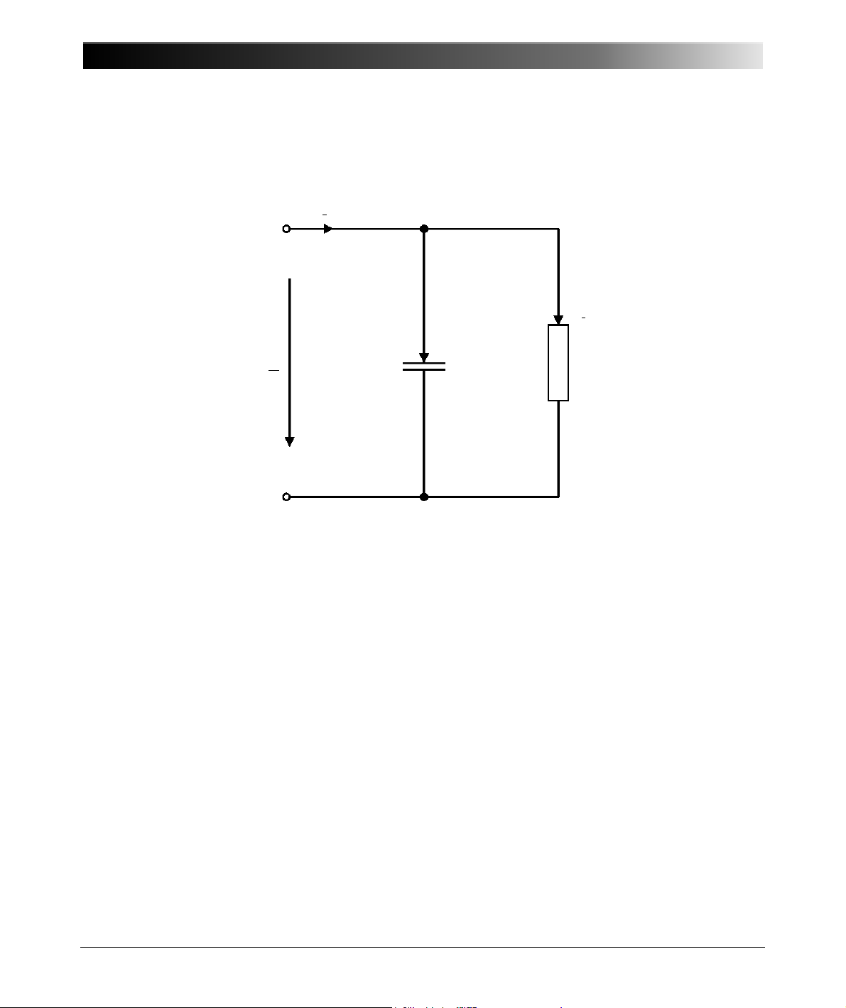
the losses (Figure 5-1). Losses can also be represented by
p
and Rs (chapter 12.1). The definition of
s
the dissipation factor and the vector diagram are shown in Figure 5-2.
Figure 5-1 Simplified circuit diagram of a capacitor
40
Page 41
Capacitance and Dissipation Factor Measurement
R
e
I
Rp
U
I
Cp
I
j
Im
δ
δtan
1
R
P
ω C
P
------------------=
Figure 5-2 Definition of dissipation factor (tan
δ) and the vector diagram
41
Page 42
CP TD1 Reference Manual V 1.44
I
m
I
CN
I
CX
δ
U
O
R
e
Withδ 1
δδϕcosδ≅tan≅
«
π
2
-- - ϕ–=
PF
DF
1 DF
2
+
------------------------=
DF
PF
1 PF
2
–
-----------------------=
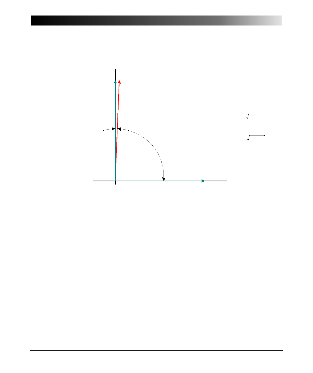
The correlation between the Dissipation Factor and Power Factor (PF = cos
and the vector diagram are shown in Figure 5-3.
Figure 5-3 Correlation between DF and PF
ϕ)
42
Page 43
Capacitance and Dissipation Factor Measurement
Kind of polarization
Suspension Rotation
Electrons Ions Dipoles
completely
reversible partly reversible
partly irreversible
All Material Glass Water
Porcelain Polar Plastics
Salt Polar Ceramics
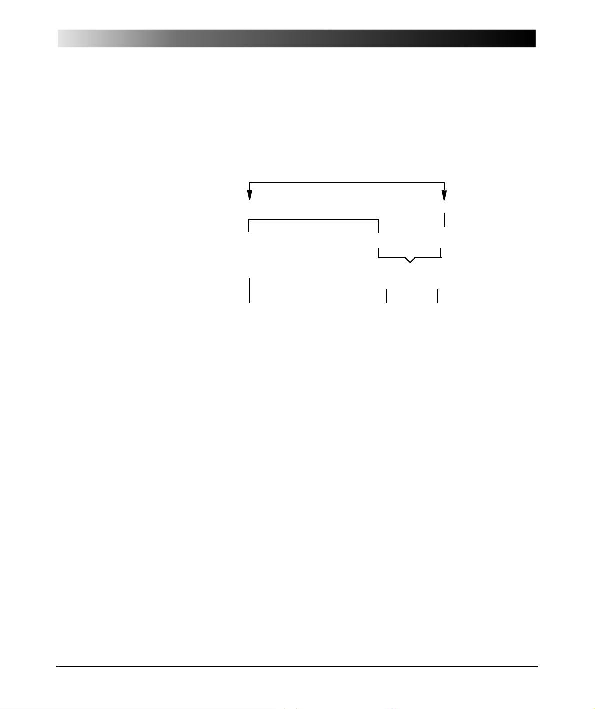
The dielectric losses in the insulation are caused by:
• movement of conductive particles
• movement of ions and electrons
• polarization effects (Figure 5-4)
Figure 5-4 Kind of polarization
43
Page 44
CP TD1 Reference Manual V 1.44
Way of electrons
without E with E
core
core
without E
with E
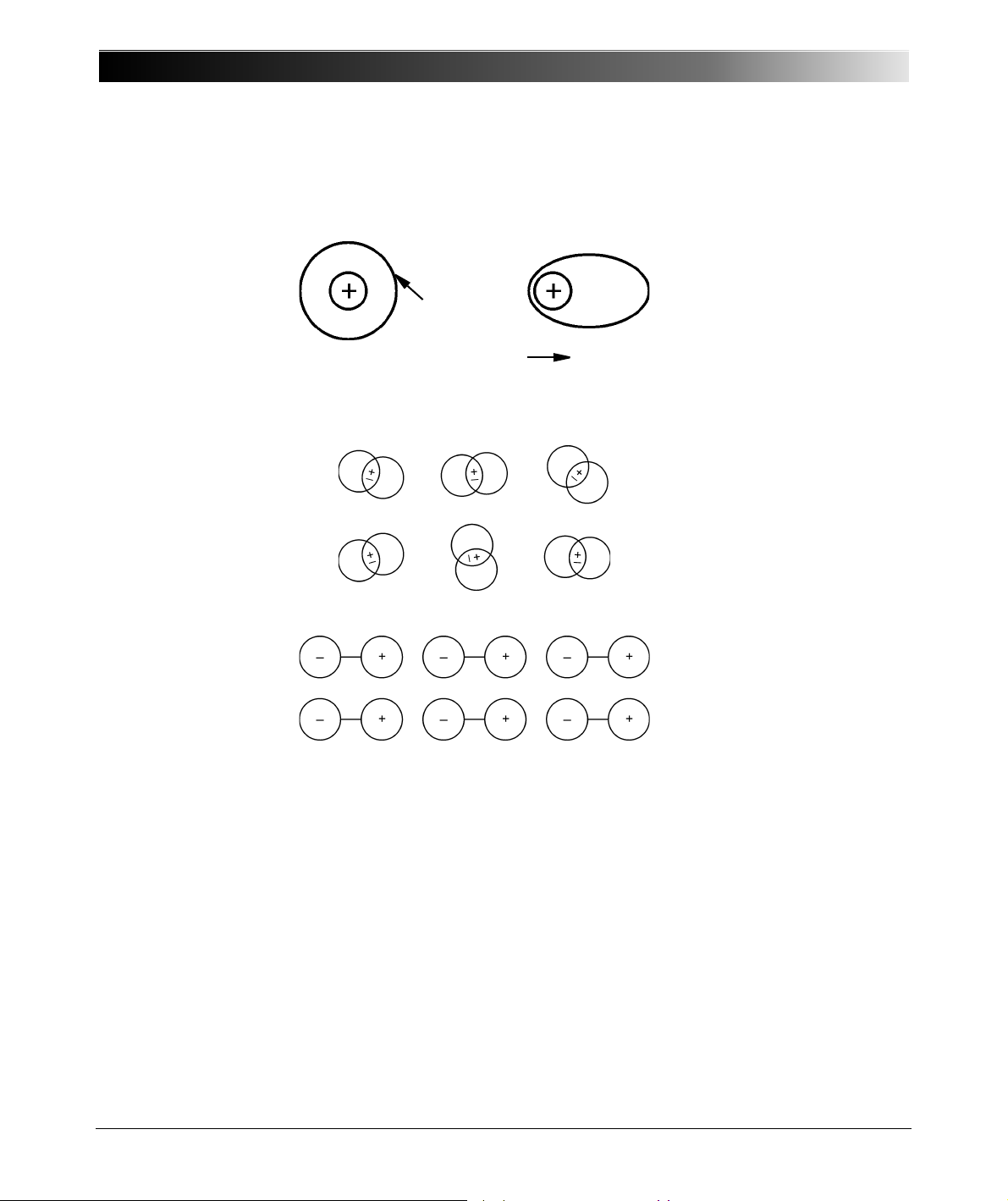
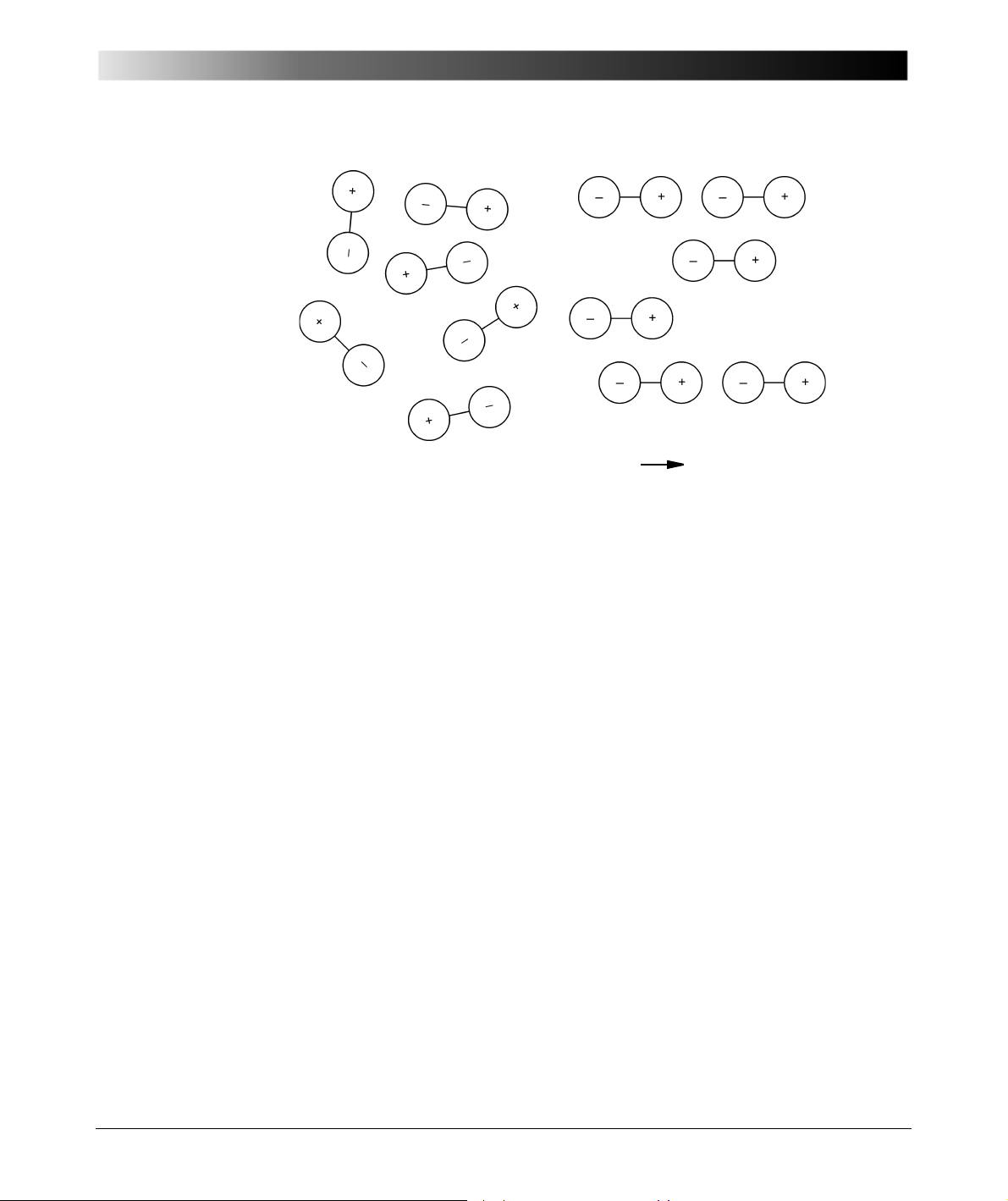
Polarization losses are generated due to suspension and rotation effects.
Suspension of electrons is completely reversible. Figure 5-5 shows this
mechanism. This kind of polarization is also called "Atom Polarization".
Figure 5-5 Polarization of electrons in the electrical field
Figure 5-6 Polarization of ions in the electrical field
44
Page 45
Capacitance and Dissipation Factor Measurement
without E with E
Figure 5-7 Polarization of dipoles in the electrical field
45
Page 46
CP TD1 Reference Manual V 1.44
E
H
+
H
+
O
2-
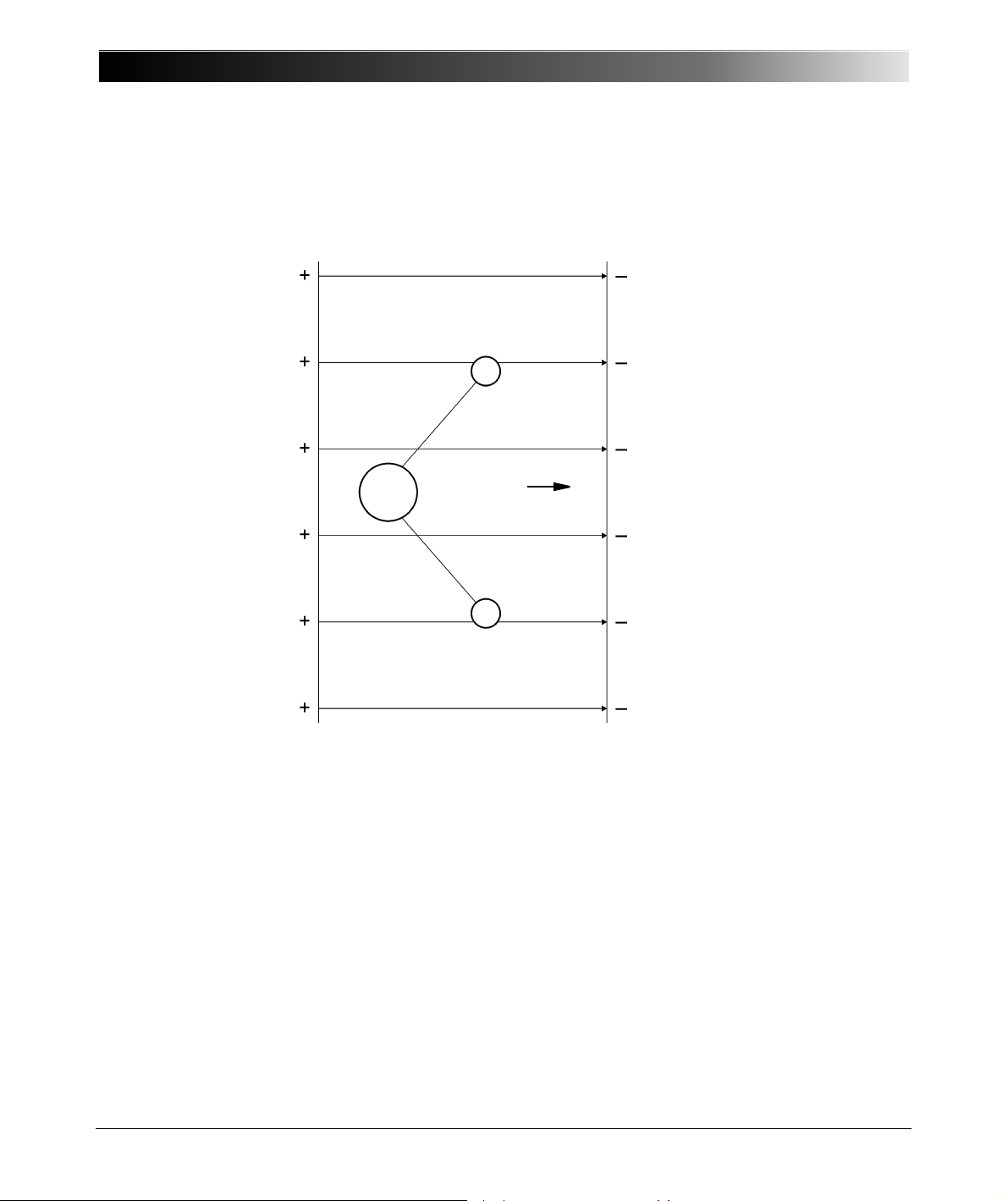
A typical dipole is a water molecule. Figure 5-8 shows such a molecule in the
electrical field. When the electrical field changes the polarity, the orientation of
the water molecule is changed by 180°. This rotation, along with the applied
frequency, causes the described losses.
Figure 5-8 Water molecule in the electrical field
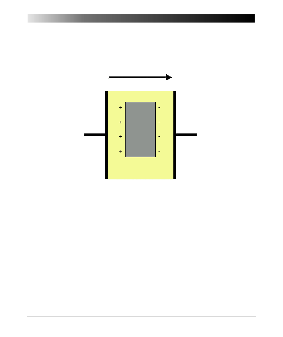
Additional losses are known as interfacial polarization. Inter-phase boundaries
(e.g., between solid and liquid insulation material) may be charged, i.e., the
electrical field moves the charge carriers in the oil; the charge carriers come to
rest upon the boundary to the solid insulation material and create a space
46
Page 47
Capacitance and Dissipation Factor Measurement
E
+—
ε 2
γ 2
ε 1 γ 1
charge region. These space charge regions are moved back and forth through
the field. This effect, for example, occurs on the interface between transformer
oil and solid insulation like paper or transformer board (Figure 5-9).
Figure 5-9 Interfacial polarization
47
Page 48
CP TD1 Reference Manual V 1.44
kV/cm
600
500
400
300
200
100
0
60
50
40
30
20
10
0
Breakdown voltage
Dissipation factor
0 20 40 60 80 100 120 140 160 180 200
Water content mg/kg
tan δ
ε
d
0
/
00
Influence of different parameters like water content,
temperature and aging on DF
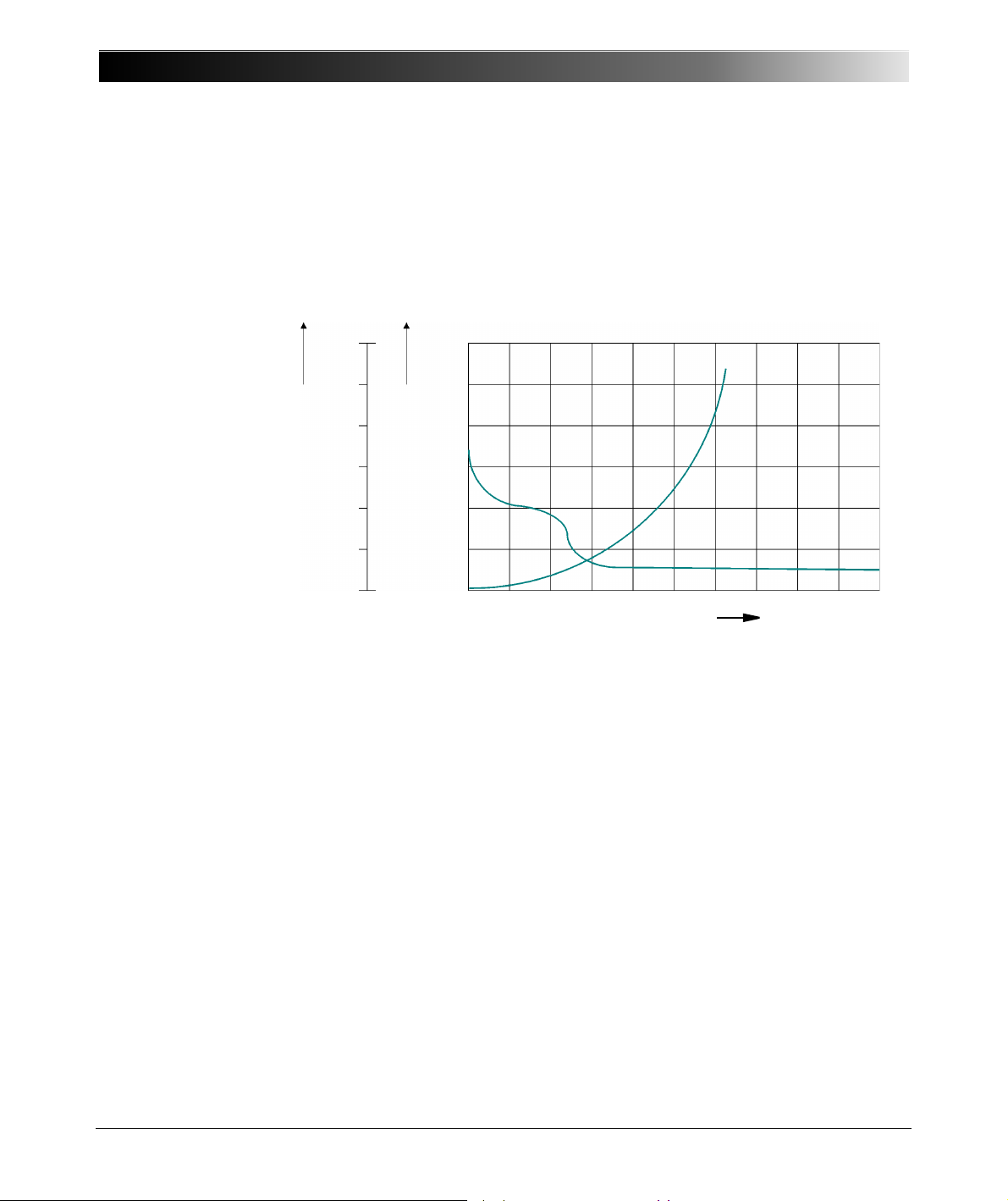
Figure 5-10 shows the breakdown voltage and the DF in oil, dependent on the
water content [2.3]. With low water content, the breakdown voltage is very
sensitive; with higher water content, the DF is a good indicator.
Figure 5-10 Breakdown voltage and DF in oil, dependent on the water
content
48
Page 49
Capacitance and Dissipation Factor Measurement
0
/
00
tan δ
10
4
10
3
10
2
10
1
1
-30 -20 -10 0 10 20 30 40 50 60 70 80 90 100 °C
Oil temperature
1
2
3
4
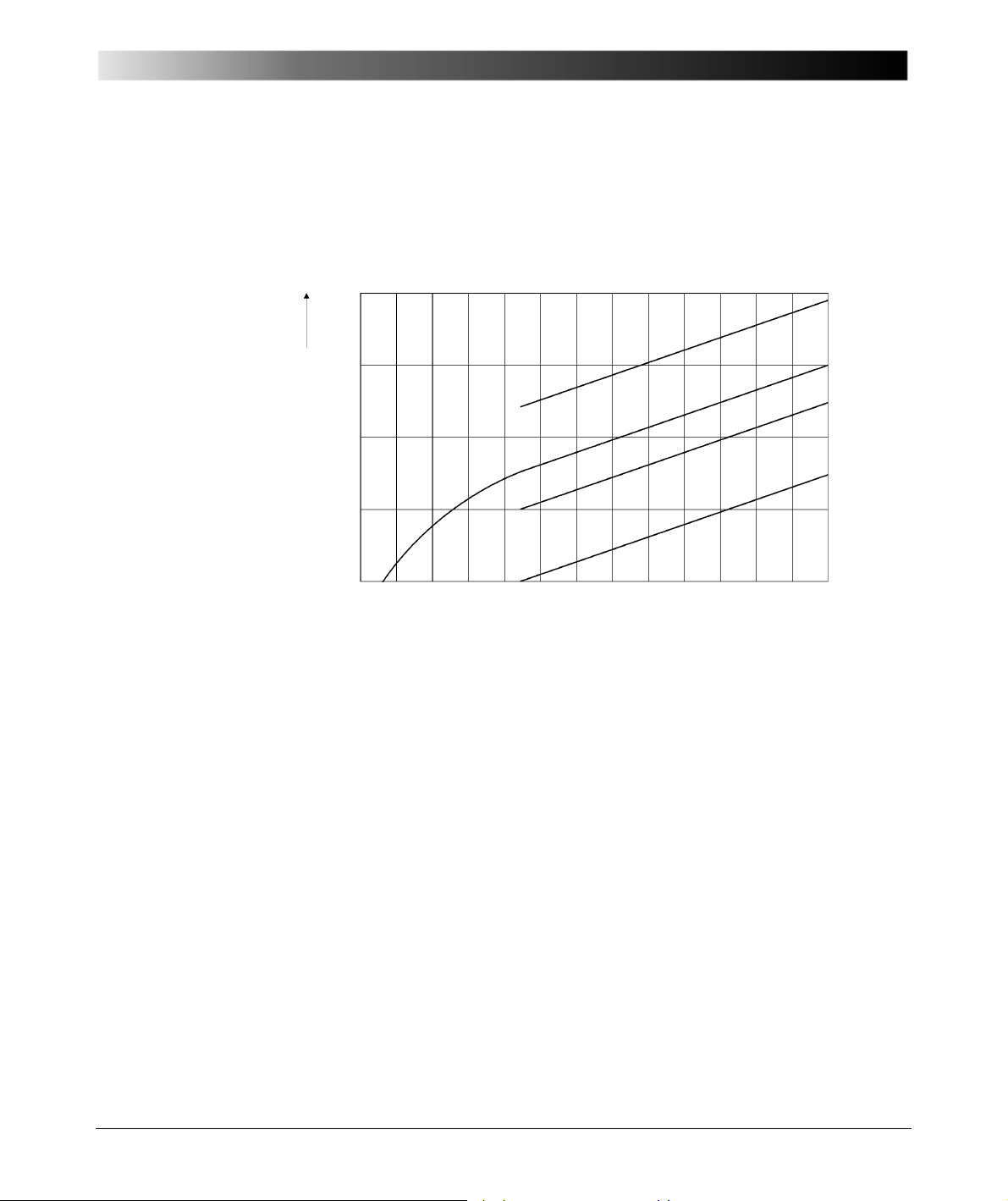
Figure 5-11 shows the DF of new and used oil, dependent on the temperature.
With higher temperatures, the viscosity of the oil decreases so the particles, ions
and electrons can move easier and faster. Thus the DF increases with
temperature [2.3].
Figure 5-11 DF of new and aged oil, dependent on temperature
Dissipation Factor: Dependency of the temperature
1 = new oil
2, 3 and 4 = used oil
49
Page 50
CP TD1 Reference Manual V 1.44
F
p20
F
pt
K
-------=
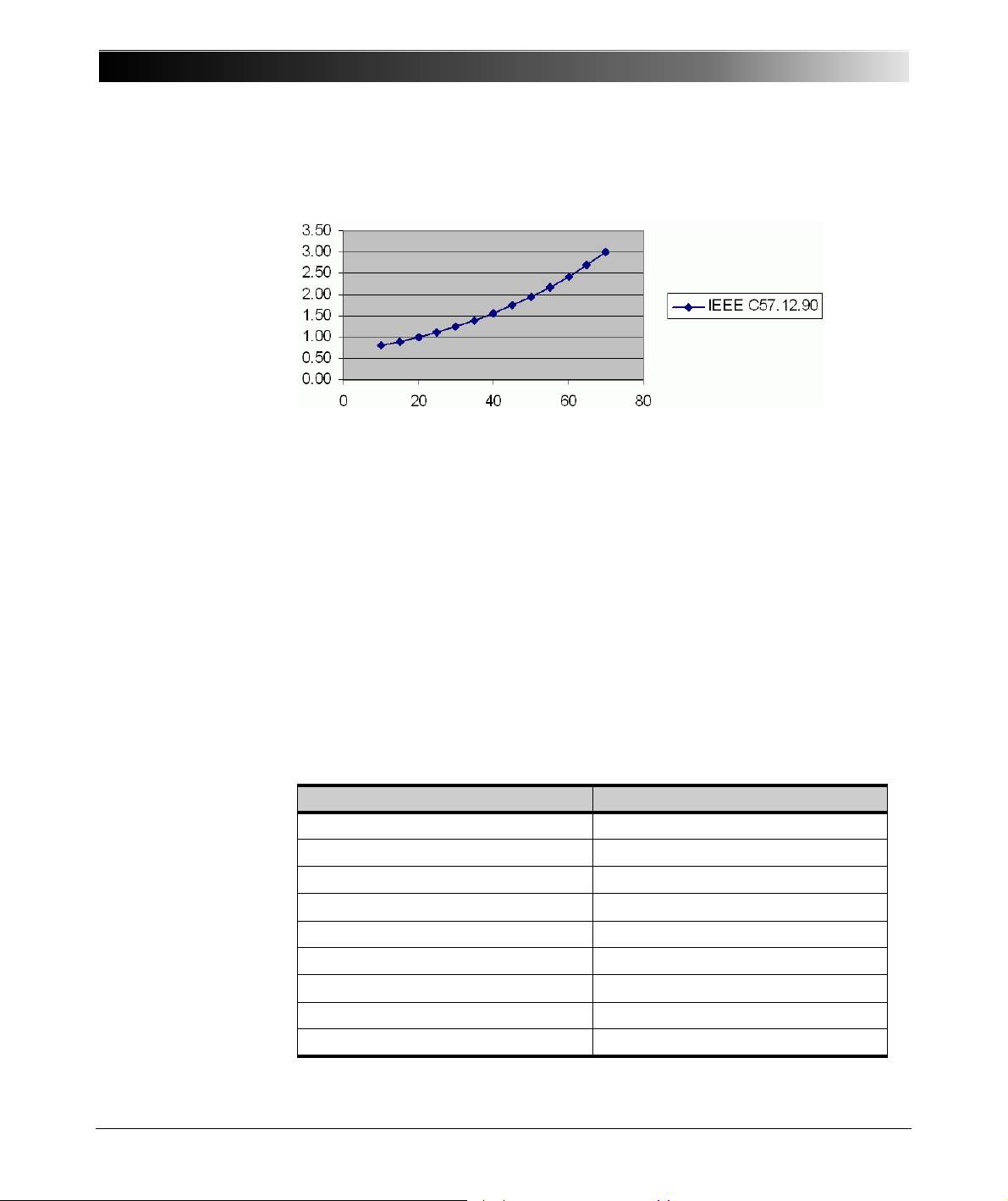
Figure 5-12 and table 5-1 show a temperature correction factor (according to
ANSI 57.12.90) for insulation based on mineral oil [2.4].
Figure 5-12 Temperature correction factor for mineral oil insulation [2.4]
where
F
is the power factor corrected to 20°C
p20
F
is the power factor measured at T
pt
T is the test temperature (°C)
K is the correction factor
Table 5-1 Temperature correction factor for mineral oil insulation [2.4]
Test temperature T (°C) Correction Factor K
10 0.80
15 0.90
20 1.00
25 1.12
30 1.25
35 1.40
40 1.55
45 1.75
50 1.95
50
Page 51
Capacitance and Dissipation Factor Measurement
0
/
00
1
0.1
0.01
Specific volume resistance ρ
10
14
10
13
10
12
020 406080°C
rr
tan δ
2
1
1,2
Table 5-1 Temperature correction factor for mineral oil insulation [2.4]
Test temperature T (°C) Correction Factor K
55 2.18
60 2.42
65 2.70
70 3.00
Note: The correction factors listed above base on insulated systems using
mineral oil as an insulating liquid. Other insulating liquids may have different
correction factors.
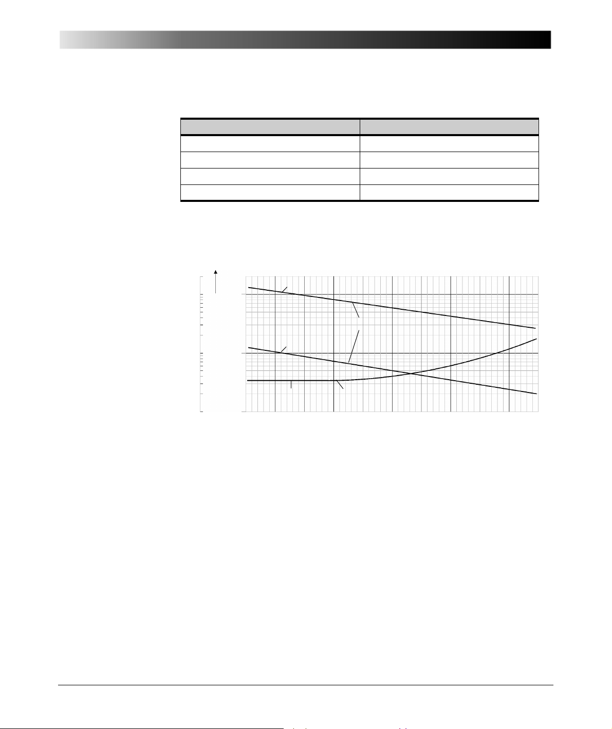
Figure 5-13 Temperature behavior of silicon liquid [2.3]
51
Page 52
CP TD1 Reference Manual V 1.44
Resin Bonded Paper
Resin Impregnated Paper
Oil Impregnated Paper
Dissipation factor x 10
2
Temperature in °C
Dissipation Factor - Dependency of the temperature
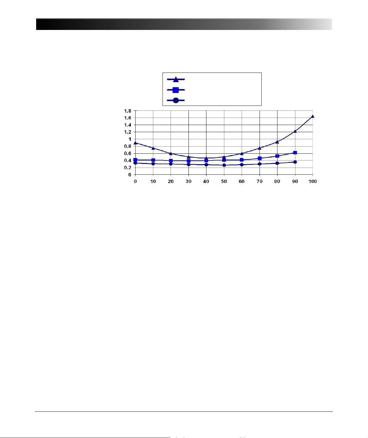
Figure 5-14 Temperature behavior RBP, RIP, and OIP bushing [2.5]
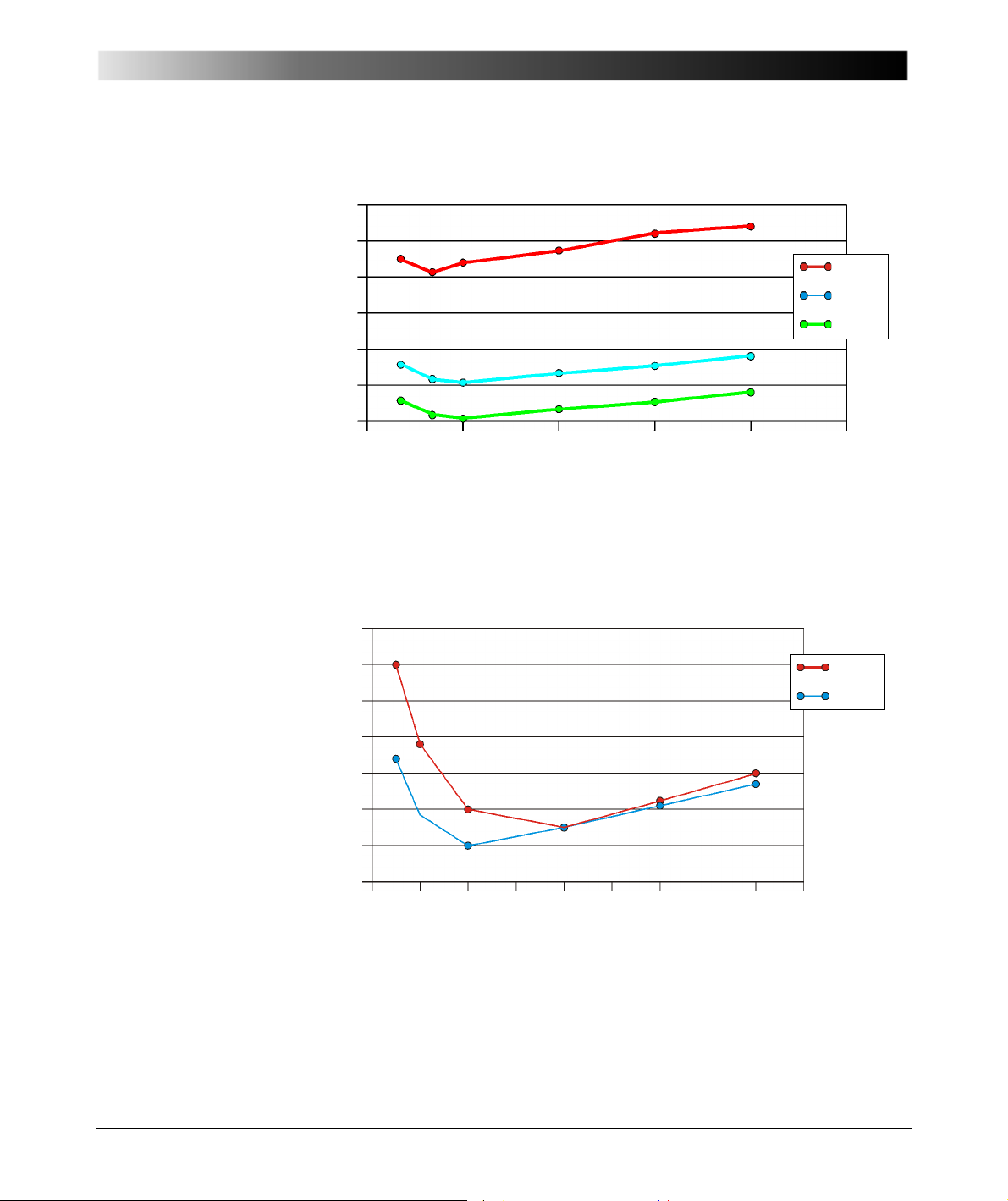
The dissipation factor is dependent on the frequency. With modern test devices
like the CPC 100 + CP TD1, it is possible to cover a wide frequency range for
capacitance and DF measurements. Up to now, fingerprint measurements for
comparison are normally available only at line frequency. The following figures
show the frequency dependency for transformer windings (oil-paper insulation)
and an OIP bushing (Figures 5-15 and 5-16).
52
Page 53
Capacitance and Dissipation Factor Measurement
0.55%
0.50%
0.45%
0.40%
0.35%
0.30%
0.25%
0.0Hz 100 Hz 200Hz 300Hz 400Hz 500Hz
L (f)
HL (f)
H (f)
0.67%
0.66%
0.65%
0.64%
0.63%
0.62%
0.61%
0.60%
0.0Hz
50.0Hz
100.0Hz
150.0Hz
200.0Hz
250.0Hz
300.0Hz
350.0Hz
400.0Hz
450.0Hz
A
B
TR 2-Winding DF (f)
Figure 5-15 Frequency scan winding to winding DF measurement (oil-
paper)
DF (f)
Figure 5-16 Frequency scan of a OIP bushing (Phase A and B)
53
Page 54
CP TD1 Reference Manual V 1.44
1.6%
1.5%
1.4%
1.3%
1.2%
1.1%
1.0%
0.9%
0.8%
0.7%
0.6%
0V 1kV 2kV 3kV 4kV 5kV 6kV 7kV 8kV
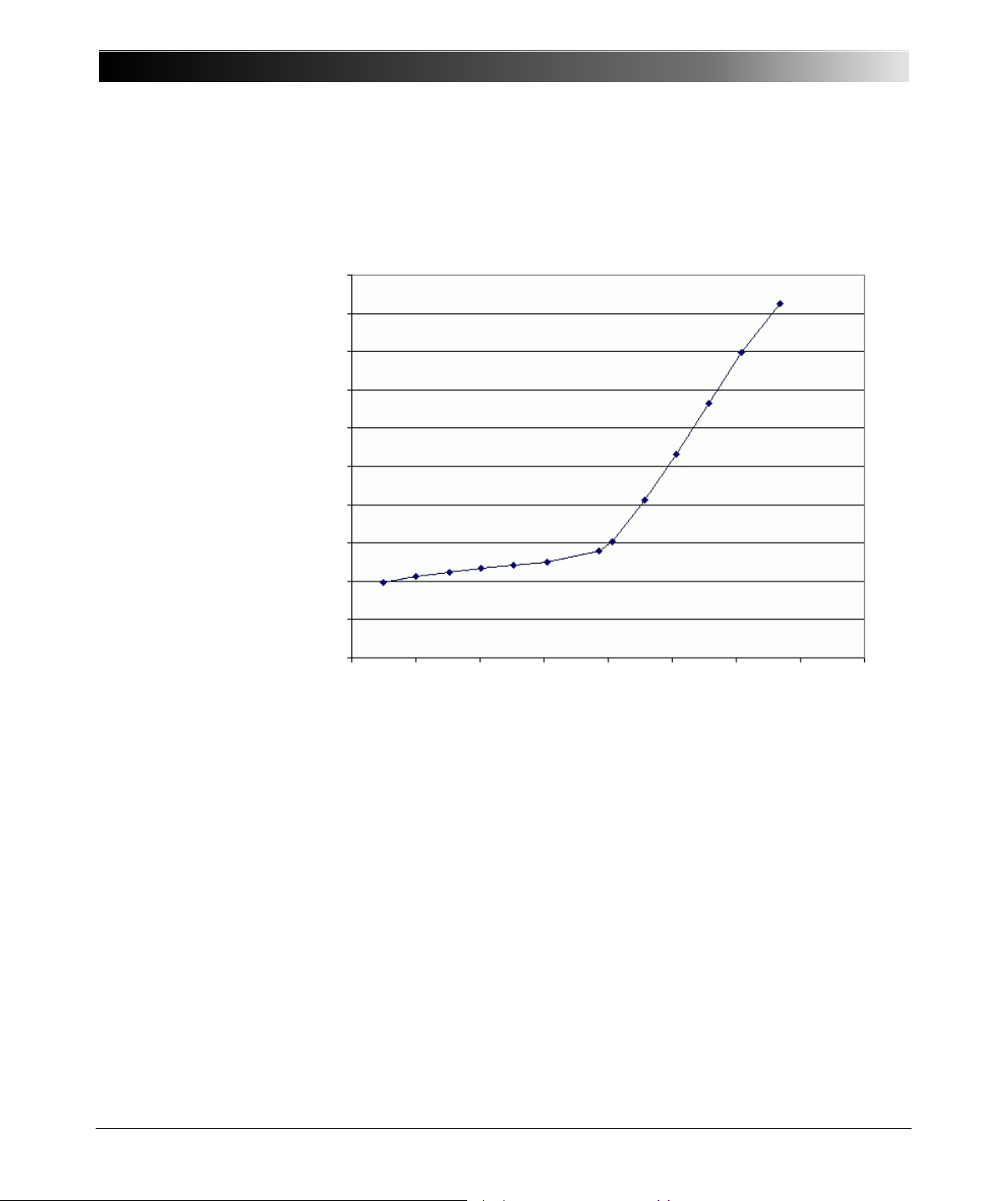
The dissipation factor is in many cases also dependent on the test voltage.
Figure 5-17 shows a measurement of a 6kV motor. Above 4kV, partial
discharges occur. This is the reason for the rise of DF.
Tan Delta Motor 6 kV
Figure 5-17 Voltage scan of a 6 kV motor
5.2 Measurement of Capacitance and Dissipation
54
Factor / Power Factor
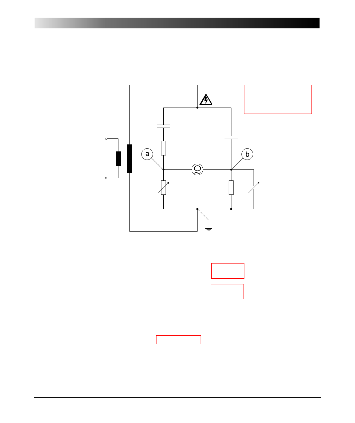
Capacitance (C) and Dissipation Factor (DF) measurement was first published
by Schering in 1919 [2.1] and utilized for this purpose in 1924 (Figure 5-18). The
serial connected C
and R1 represent the test object with losses, C2 the loss-
1
Page 55
Capacitance and Dissipation Factor Measurement
C
1
C
2
R
1
R
3
R
4
C
4
R
1
1
jω C
1
------------ -+
R
3
-------------------------
1
R
4
----- - jωC
4
+
jωC
2
-------------------------=
R
1
R
3
----- -
C
4
C
2
------
R
1
C
4
C
2
------
R
3
×==
C1R3× C2R4× C
1
R
4
R
3
----- -
C
2
×==
δtan R1ωC
1
×=
δtan C
4
R
3
C
2
------
×ω
R
4
R
3
----- -
×× C
2
×=
δωC4× R4×=tan
free reference capacitor. The parallel circuit diagram shown in Figure 5-1 can be
transferred as a direct equivalent into this serial diagram at specified frequencies
(section 12.1).
Figure 5-18 Schering bridge
Real parts:
Imaginary parts:
55
Page 56
CP TD1 Reference Manual V 1.44
U0(t)
U
N
(t) UX(t)Z
1
Z
2
I
CN
I
CX
Z
N
CXZX, L
X
C
N
Reference path Measurement path
Figure 5-19 CP TD1 measuring principle
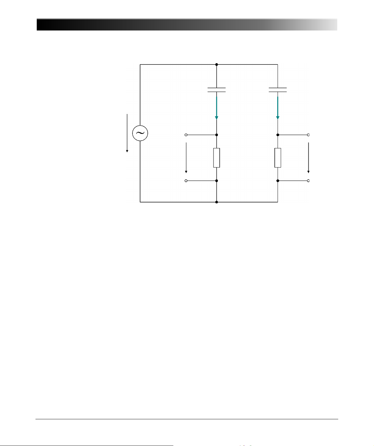
The CP TD1 test system utilizes a method similar to that of the Schering bridge.
The main difference is that the CP TD1 measuring principle (Figure 5-19) does
not require tuning for measuring C and DF. C
is a gas insulated reference
n
capacitor with losses below 10E-5. For laboratory use, such capacitors are
regularly used to obtain precise measurements, as the ambient lab temperature
normally ranges between 20 - 25 °C (68 - 77 °F). When carrying out on-site
measurements, however, temperatures can vary significantly, which results in
changes of the electrodes geometry.
56
Page 57
Capacitance and Dissipation Factor Measurement
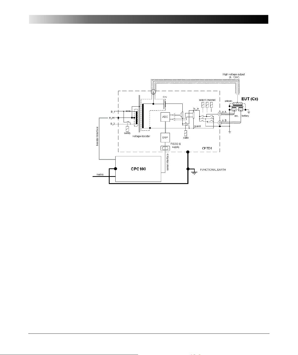
The CP TD1 takes all these effects into account and compensates for them
electronically, so it is now possible for the first time to measure in the field down
to DF = 5 x 10E-5. Figure 5-20 shows the complete equivalent circuit diagram.
Figure 5-20 CP TD1 measuring principle
To the present day, the dissipation or dissipation factor was measured only at
line frequency. With the power source described in [2.2], it is now possible to
make these insulation measurements in a wide frequency range. Beside the
possibility to apply frequency scans, measurements can be made at frequencies
different from the line frequency and their harmonics. With this principle,
measurements are possible also in the presence of high electromagnetic
interference in high-voltage substations.
57
Page 58
CP TD1 Reference Manual V 1.44
CoreTL
H
C
H
C
H-L
C
L-T
C
H-T
C
T
C
L
Tank
G
5.3 "UST" and "GST" Measurements Using the Guard Technology
In electrical devices like power transformers there are a lot of insulation gaps,
which have to be checked separately:
• Winding to winding
• Winding to tank & core
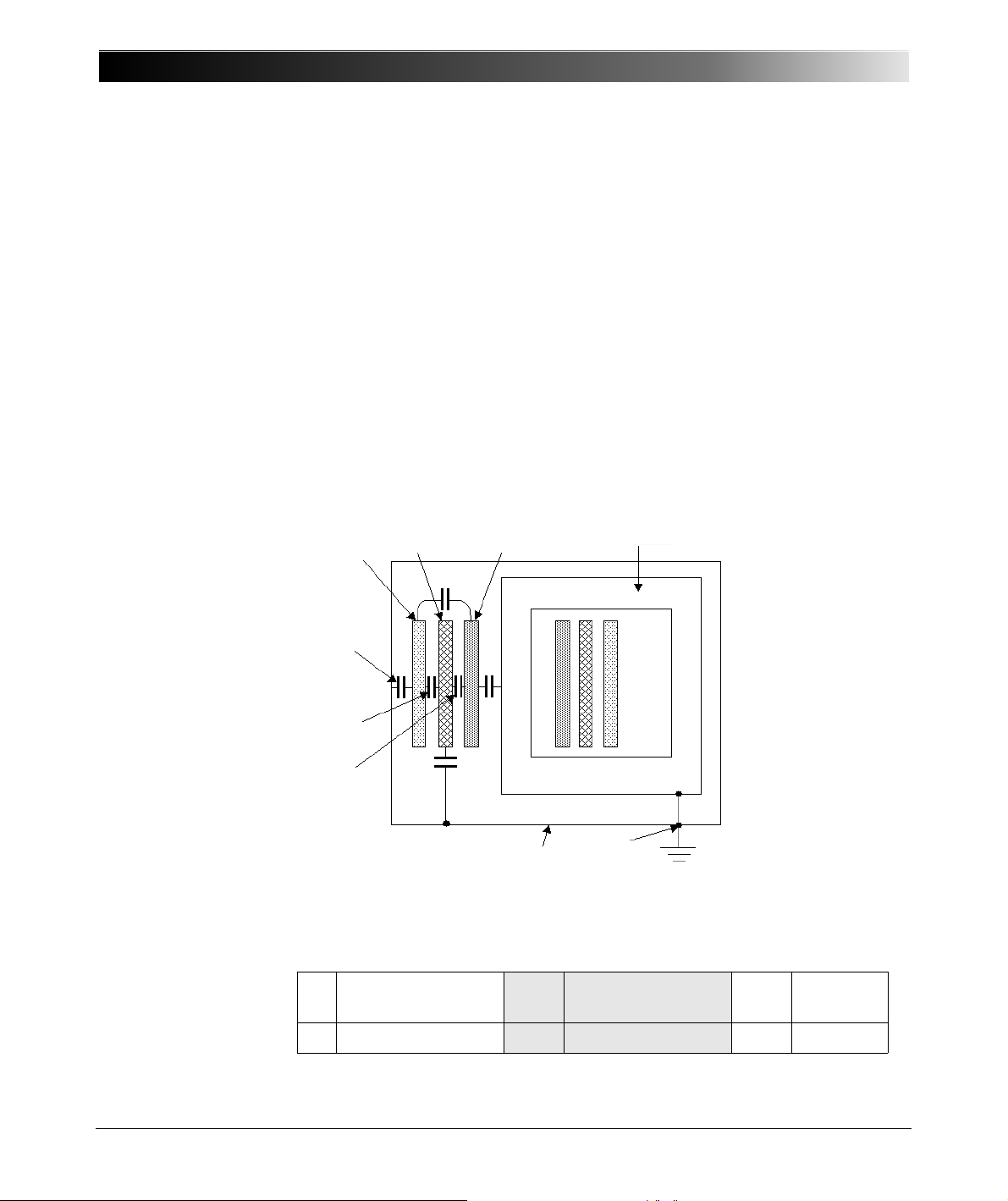
• Bushings
A three-winding transformer with the different insulation gaps is shown in figure
5-21. Only one phase is drawn. With a three-phase transformer the equivalent
circuit diagram is very similar, because normally the phases of the high-voltage
(H), the low-voltage (L) and the tertiary (T) windings are connected internally in
y or delta. This way only the sum of all three phases can be measured, the single
phases can not be measured separately.
Figure 5-21 Three-phase transformer with winding capacitances
H High-Voltage
58
winding
L Low-Voltage winding C L Cap. L to Ground C L-T Cap. L to T
C H Cap. H to Ground C H-L Cap. H to
L
Page 59
Capacitance and Dissipation Factor Measurement
IN A
IN B
C
1
C
2
C
3
UST-A
C = C
1
Guard
Measuring input
T Tertiary winding C T Cap. T to Ground C H-T Cap. H to
T
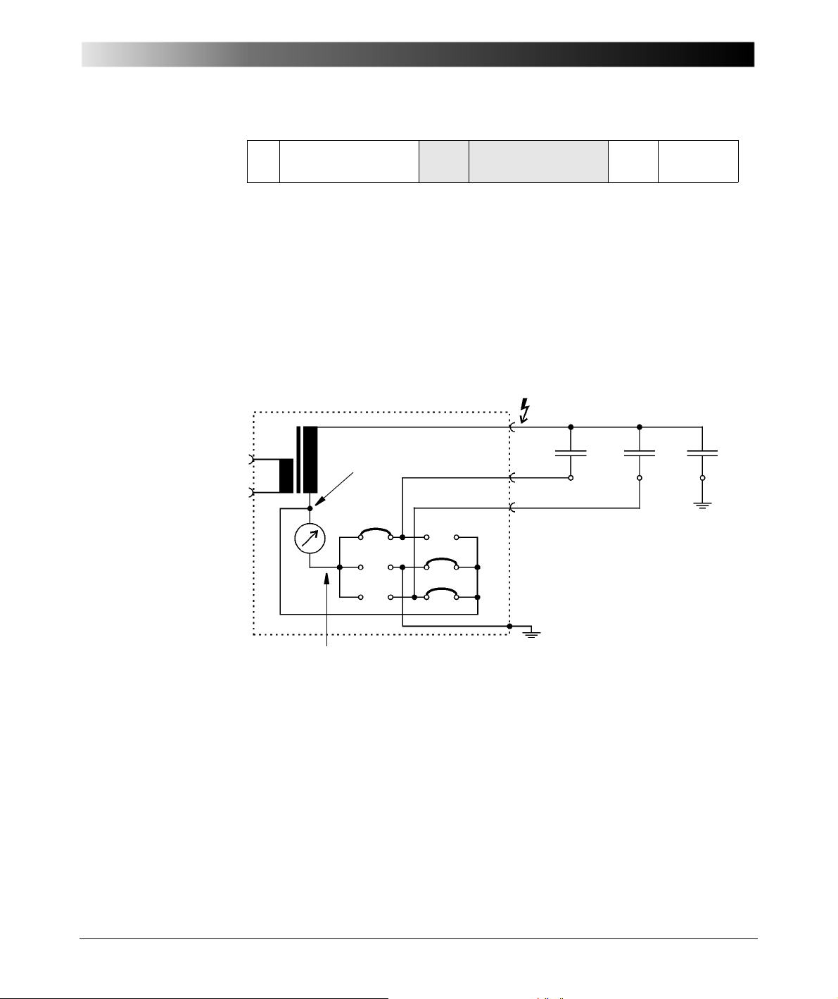
For the separate measurement of all capacitors a so-called guard technique is
necessary. The single capacitors connected to guard are energized but not
measured.
In Figure 5-22 a block diagram of the CP TD1 is shown with the guard
connection and measuring input. In the example case C
capacitors, connected to the CP TD1. C
connected to input B and C
energized. Only C
is measured, because the relay matrix only connects C1 to
1
is connected to ground. All three capacitors are
3
is connected to input A, C2 is
1
the measuring input (instrument), whereas the currents through C
bypassed. C
and C3 are connected to the foot-point of the HV transformer
2
, C2 and C3 are
1
and C3 are
2
(GUARD).
Figure 5-22 CP TD1 block diagram with GUARD and measuring input
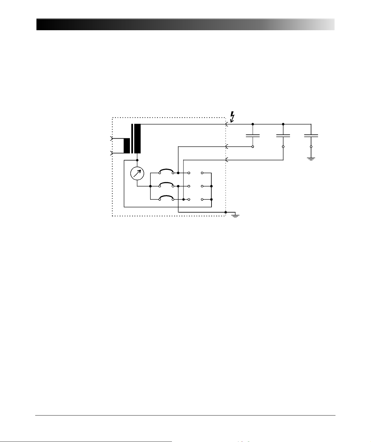
To get more familiar with this technique we want to measure C HL, C HT and C
H of Figure 5-21. The high-voltage winding is connected to the test voltage
(high-voltage output of the CP TD1), the low-voltage winding is connected to IN
A and the tertiary winding is connected to IN B.
59
Page 60
CP TD1 Reference Manual V 1.44
IN A
IN B
C
HL
C
HT
C
H
GST
C = CHL + CHT + C
H
If big capacitance values are expected, we should start with a GST
measurement first. In the GST mode all connected capacitors are measured in
parallel (C HL + C HT + C H). This way we can check if the CP TD1 is overloaded
during the measurements or not (Figure 5-23) and we can check the single
measurements. The capacitance value out of this measurement must be the
sum of the following single measurements.
60
Figure 5-23 CP TD1 block diagram of GST mode
Page 61
Capacitance and Dissipation Factor Measurement
IN A
IN B
C
HL
C
HT
C
H
UST-A
C = C
HL
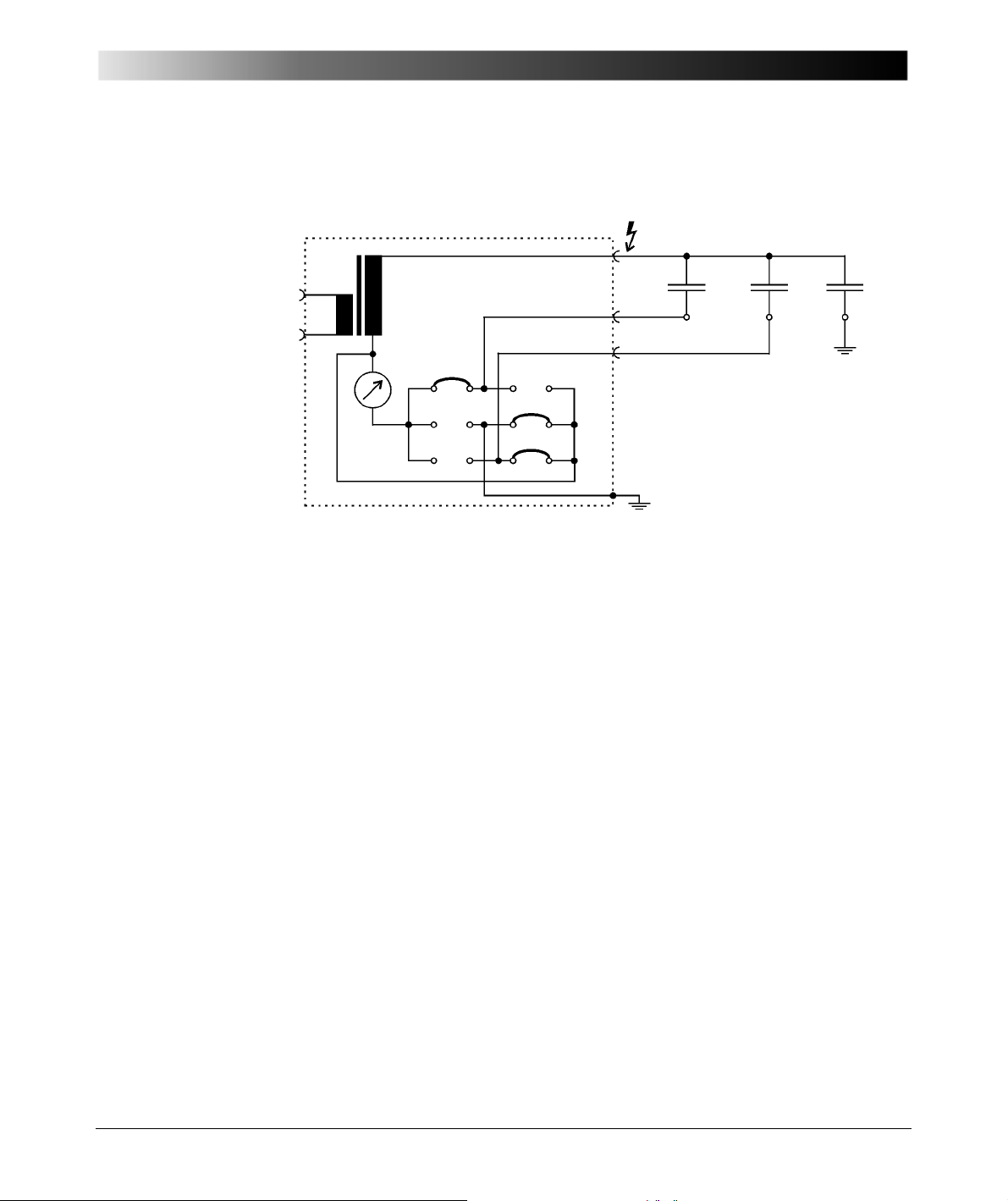
Now we want to measure C HL. The connection diagram is shown in Figure
5-24. The measuring mode is UST-A.
Figure 5-24 Measurement of C HL in UST-A mode, C HT and C H are
guarded
61
Page 62
CP TD1 Reference Manual V 1.44
IN A
IN B
C
HL
C
HT
C
H
UST-B
C = C
HT
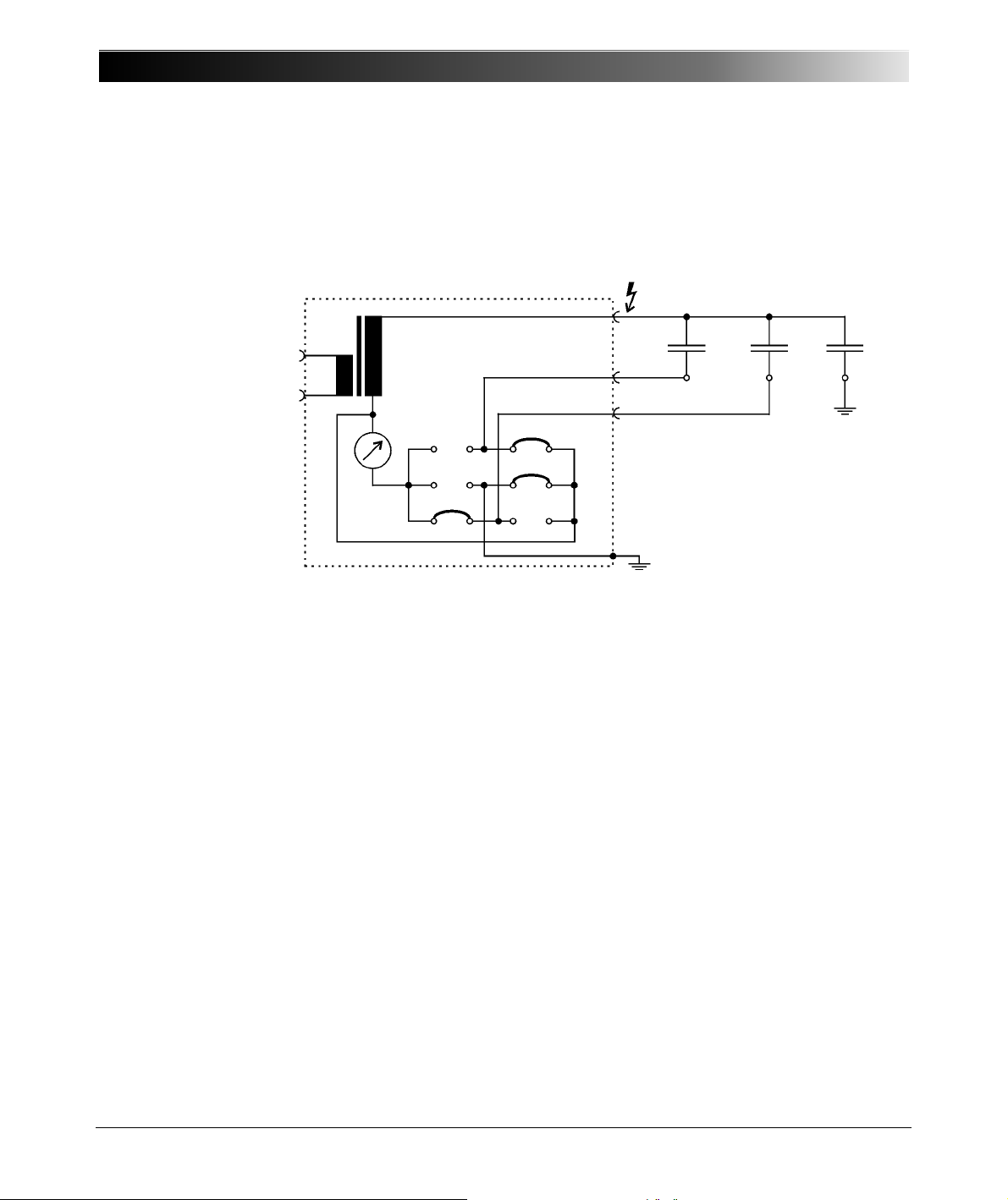
Next measurement is C HT. The connection diagram is shown in Figure 5-25.
The measuring mode is UST B. Without the GUARD technique it would not be
possible to measure C HT separately, because C HL in series to C LT are in
parallel to C HT. Only by connecting L to GUARD the current flowing to L is not
measured.
Figure 5-25 Measurement of C HT in UST-B mode, C HL and C H are
guarded
62
Page 63
Capacitance and Dissipation Factor Measurement
IN A
IN B
C
HL
C
HT
C
H
GSTg-A+B
C = C
H
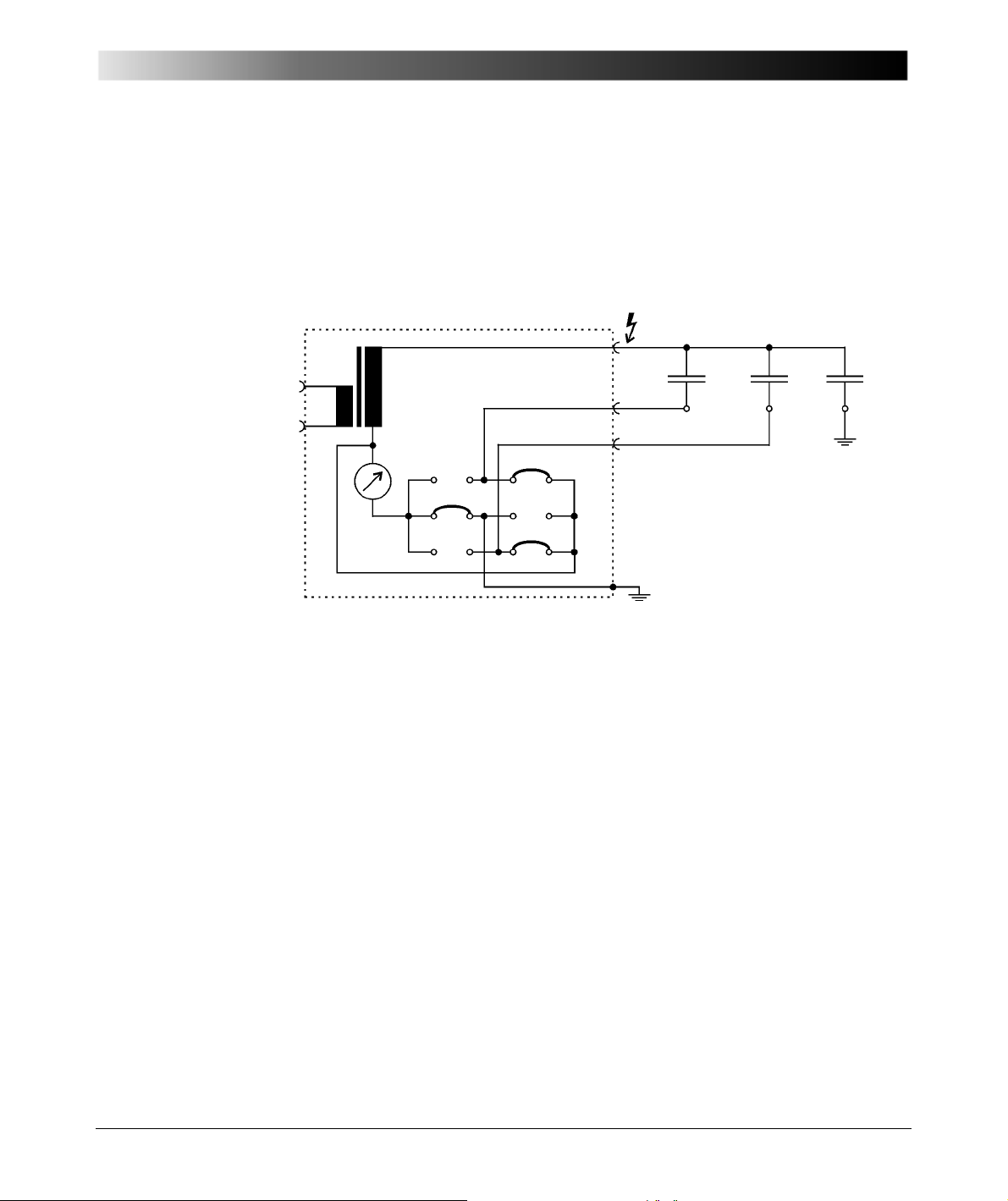
The last measurement is C H. Figure 5-26 shows this connection diagram. The
measuring mode is GSTg-A+B. C HL and C HT are not measured, because they
are connected to GUARD.
The build-in relay matrix enables the described four different measurements
without any rewiring. This principle can be used not only for transformers, but
also for any system with partial capacitors inside.
Figure 5-26 Measurement of C H in GST-gA+B mode, C HL and C HT are
5.4 References
[2.1] Schering, H.: "Brücke für Verlustmessungen", Tätigkeitsbericht
[2.2] Hensler, Th., Kaufmann, R., Klapper, U., Krüger, M., Schreiner,
[2.3] Krüger, M.: "Prüfung der dielektrischen Eigenschaften von
[2.4] "IEEE Standard Test Code for Liquid-Immersed Distribution,
guarded
der Physikalisch-Technischen Reichsanstalt, Braunschweig
1919
S.: "Portable testing device", US Patent 6608493, 2003
Isolierflüssigkeiten", ÖZE, No. 5, Vienna, May 1986
Power, and Regulating Transformers", IEEE Std C57.12.901999
63
Page 64

CP TD1 Reference Manual V 1.44
[2.5] Seitz, V.: "Vorbeugende Instandhaltung an
Leistungstransformatoren – Betriebsbegleitende Messungen
an Stufenschaltern und Durchführungen, OMICRON
Anwendertagung 2003, Friedrichshafen
64
Page 65
6 Power Transformers
Cellulose
Overheated Oil
Corona
Arcing
6.1 Introduction
Due to ever-increasing pressure to reduce costs, the power industry is forced to
keep old power facilities in operation as long as possible. In most European
countries, about one third of the transformers are over 30 years old. Even
transformers older than 50 years are still in service. A regular check of the
operating conditions becomes more and more important with the advancing age
of transformers. The Dissolved Gas Analysis is a proven and meaningful method
for finding a fault as soon as possible if increased proportions of hydrogen and
hydrocarbon gases are found in the oil. This way, important preventative
maintenance can be performed in time to avoid an unexpected total failure.
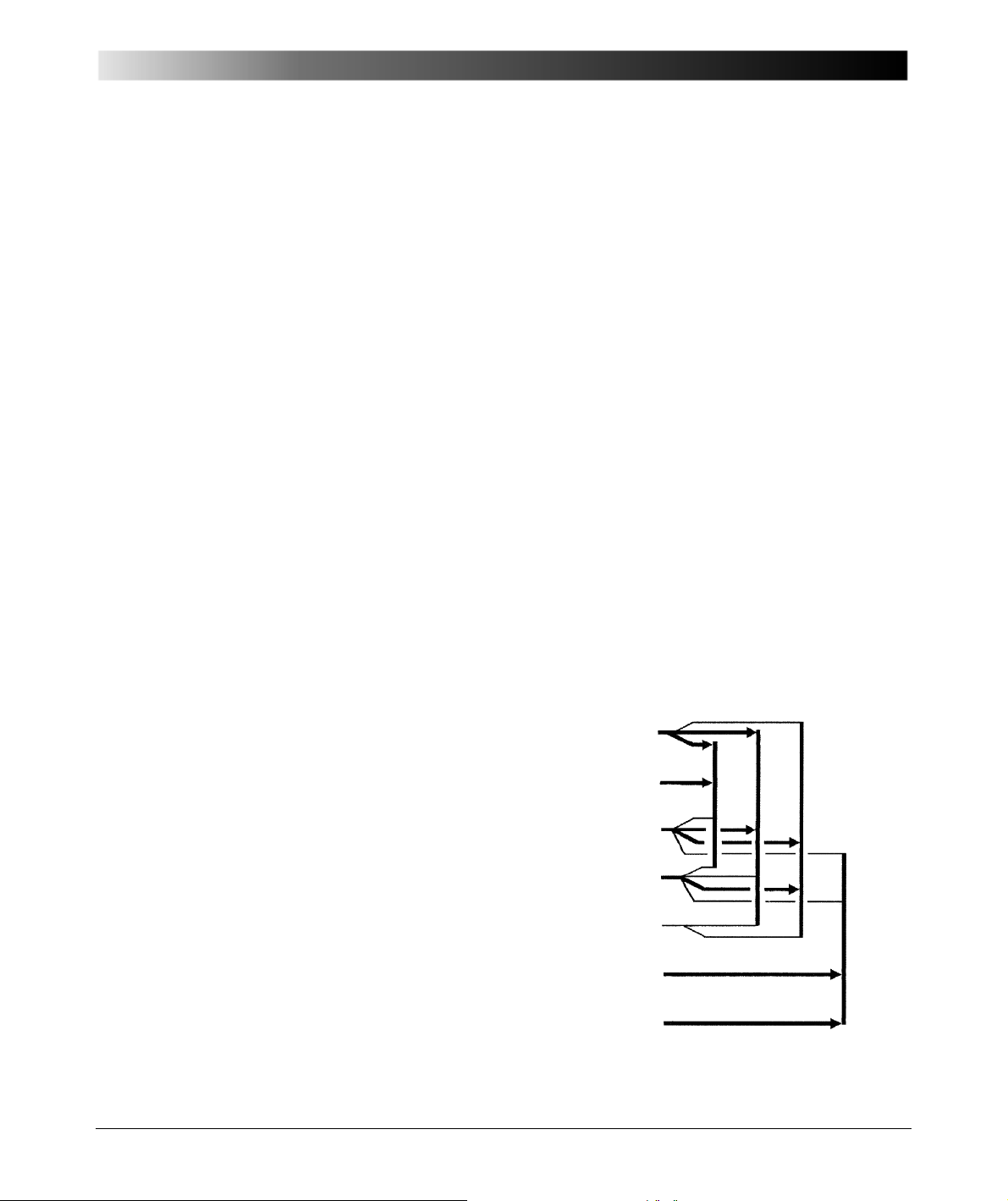
DGA analysis and interpretation of results [3.1]
On the left are gases the oil specialist looks for in the gas-in-oil-analysis. On the
right are possible origins of these gases. When these gases exceed the levels
shown in the middle columns, the analyst uses the transformer history, the type
of gases present, as well as the relative amounts, to determine any indication of
transformer problems.
Power Transformers
Hydrogen H
Acetylene C
Methane CH
Ethylene C
Ethane C
Carbon
monoxide
Carbon
dioxide
3)
CO 200
2)
CO
Gas Normal
ppm
2
2H2
4
2H4
2H6
2
200 500
2000
Abnormal
1)
ppm
515
50 120
80 170
35 75
1)
2)
500
3500
65
Page 66
CP TD1 Reference Manual V 1.44
C2H
2
C2H
4
-------------
CH
4
H
2
---------- -
C2H
4
C2H
6
-------------
Legend:
Major gases
Minor gases
1)
ppm = parts per million by volume (gas/liquid)
2)
Previous limits for CO were 500 and 700 ppm
3)
Previous limits for CO2 were 2000 and 10000 ppm
Behind the absolute value of gas content are the quotients of the gas
components, which also allow for additional information (Table 6-1) [3.2].
Table 6-1 Dissolved Gas Analysis [3.2]
Type of fault
PD Partial discharge < 0.01 < 0.1 < 0.2
D1 Discharge with low energy > 1 0.1 - 0.5 > 1
D2 Discharge with high energy 0.6 - 2.5 0.1 - 1 > 2
T1 Thermal fault T < 300°C < 0.01 > 1 < 1
T2 Thermal fault T < 700°C < 0.1 > 1 1 - 4
T3 Thermal fault T > 700°C < 0.2 > 1 > 4
66
Page 67
Power Transformers
Possible Faults and Possible Findings
Table 6-2 Possible Faults and Possible Findings [3.3]
Key gases Possible Faults Possible Findings
H
, possible trace of
2
CH
and C2H6.
4
Possible CO.
, CH4 (some CO if
H
2
discharges involve paper
insulation).
Possible trace amounts
of C
H
.
2H6
, CH4, C2H6, C2H4
2
and the key gas for
arcing C
2H2
will be
present perhaps in large
amount. If C
is being
2H2
generated, arcing is still
going on. CO will be
present if paper is being
heated.
H
, CO. Thermal fault less than
2
H
, CO, CH4, C2H6,
2
C
2H4
All the above gases and
acetylene in large
amounts.
Partial discharges
(corona)
Low energy discharges
(sparking). May be static
discharges.
High energy discharges
(arcing).
300°C in an area close
to paper insulation
(paper is being heated).
Thermal fault between
300°C and 700°C.
High energy electrical
arcing. Thermal fault of
700°C and above.
Weakened insulation
from aging and electrical
stress
Pinhole punctures in
paper insulation with
carbon and carbon
tracking.Possible carbon
particles in oil.Possible
loose shield, pour
grounding of metal
objects.
Metal fusion (poor
contacts in tap changer
or lead connections).
Weakened insulation
from aging and electrical
stress. Carbonized oil.
Paper destruction if it is
in the arc path or
overheated.
Discoloration of paper
insulation. Overloading
and/or cooling problem.
Bad connection in leads
or tap changer. Stray
current path and/or stray
magnetic flux.
Paper insulation
destroyed. Oil heavily
carbonized.
Same as above with
metal discoloration.
Arcing may have caused
a thermal fault
67
Page 68
CP TD1 Reference Manual V 1.44
Transformer Faults
Table 6-3 Transformer Faults [3.3]
Fault Examples
Partial discharges Discharges in gas-filled cavities in insulation,
Discharge of low energy Sparking or arcing between bad connections
Discharge of high energy Flashover, tracking or arcing of high local
Overheating less than 300°C Overloading the transformer in emergency
resulting from incomplete impregnation, high
moisture in paper, gas in oil supersaturation
or cavitation (gas bubbles in oil), leading to X
wax formation on paper.
of different floating potential, from shielding
rings, toroids, adjacent discs or conductors of
different windings, broken brazing, closed
loops in the core. Additional core grounds.
Discharges between clamping parts, bushing
and tank, high voltage and ground, within
windings. Tracking in wood blocks, glue of
insulating beam, winding spacers. Dielectric
breakdown of oil, load tap changer breaking
contact.
energy or with power follow-through. Short
circuits between low voltage and ground,
connectors, windings, bushings and tank,
windings and core, copper bus and tank, in oil
duct. Closed loops between two adjacent
conductors around the main magnetic flux,
insulated bolts of core, metal rings holding
core legs.
situations. Blocked or restricted oil flow in
windings. Other cooling problem, pumps
valves, etc. Stray flux in damping beams of
yoke.
68
Page 69
Power Transformers
Table 6-3 Transformer Faults [3.3]
Fault Examples
Overheating 300°C - 700°C Defective contacts at bolted connections
(especially busbar), contacts with tap
changer, connections between cable and
draw-rod of bushings. Circulating currents
between yoke clamps and bolts, clamps and
laminations, in ground wiring, bad welds or
clamps in magnetic shields. Abraded
insulation between adjacent parallel
conductors in windings.
Overheating over 700°C Large circulating currents in tank and core.
Minor currents in tank walls created by high
uncompensated magnetic field. Shorted core
laminations.
Notes on Table :
1. X wax formation comes from paraffinic oils (paraffin based). These are not
used in transformers at present in the United States but are predominate in
Europe.
2. The last overheating problem in the table says "over 700°C". Recent
laboratory discoveries have found that acetyl can be produced in trace
amounts of 500°C, which is not reflected in this table. We have several
transformers that show trace amounts of acetylene that are probably not
active arcing but are the result of high-temperature thermal faults as in the
example. It may also be the result of one arc, due to a nearby lightning strike
or voltage surge.
3. A bad connection at the bottom of a bushing can be confirmed by comparing
infrared scans of the top of a bushing with a sister bushing. When loaded,
heat from a poor connection at the bottom will migrate to the top of the
bushing, which will display a markedly higher temperature. If the top
connection is checked and found tight, the problem is probably a bad
connection at the bottom of the bushing.
69
Page 70

CP TD1 Reference Manual V 1.44
In addition to the previous table , it should be taken into account that overheating
is often caused by bad contacts in the tap selector. In order to find out the reason
for high gas values, further tests have to be performed on the transformer.
Common test methods are:
• Winding resistance measurement
• On-Load Tap Changer (OLTC) test
• Turns ratio measurement
• Excitation current measurement
• Measurement of leakage reactance
• Capacitance and Dissipation factor measurement
All the mentioned tests can be done with the CPC 100 + CP TD1. This
instrument is the ideal test and analysis instrument for transformer diagnosis
with these measuring possibilities.
6.2 Capacitance and DF Measurement of Transformer Windings
General
• The transformer must be taken out of service and completely isolated
• The proper grounding of the transformer tank has to be checked.
• The bushing high-voltage terminals must be isolated from the connection
• All bushing terminals of one winding group, which means A, B, C (and
from the power system.
lines.
Neutral) of high-voltage winding, A, B, C (and Neutral) of low-voltage
70
Page 71
Power Transformers
N (L) C (L)
A (L) B (L)
A (H) B (H) C (H) N (H)
H
L
T
B (T)
C (T)
A (T)
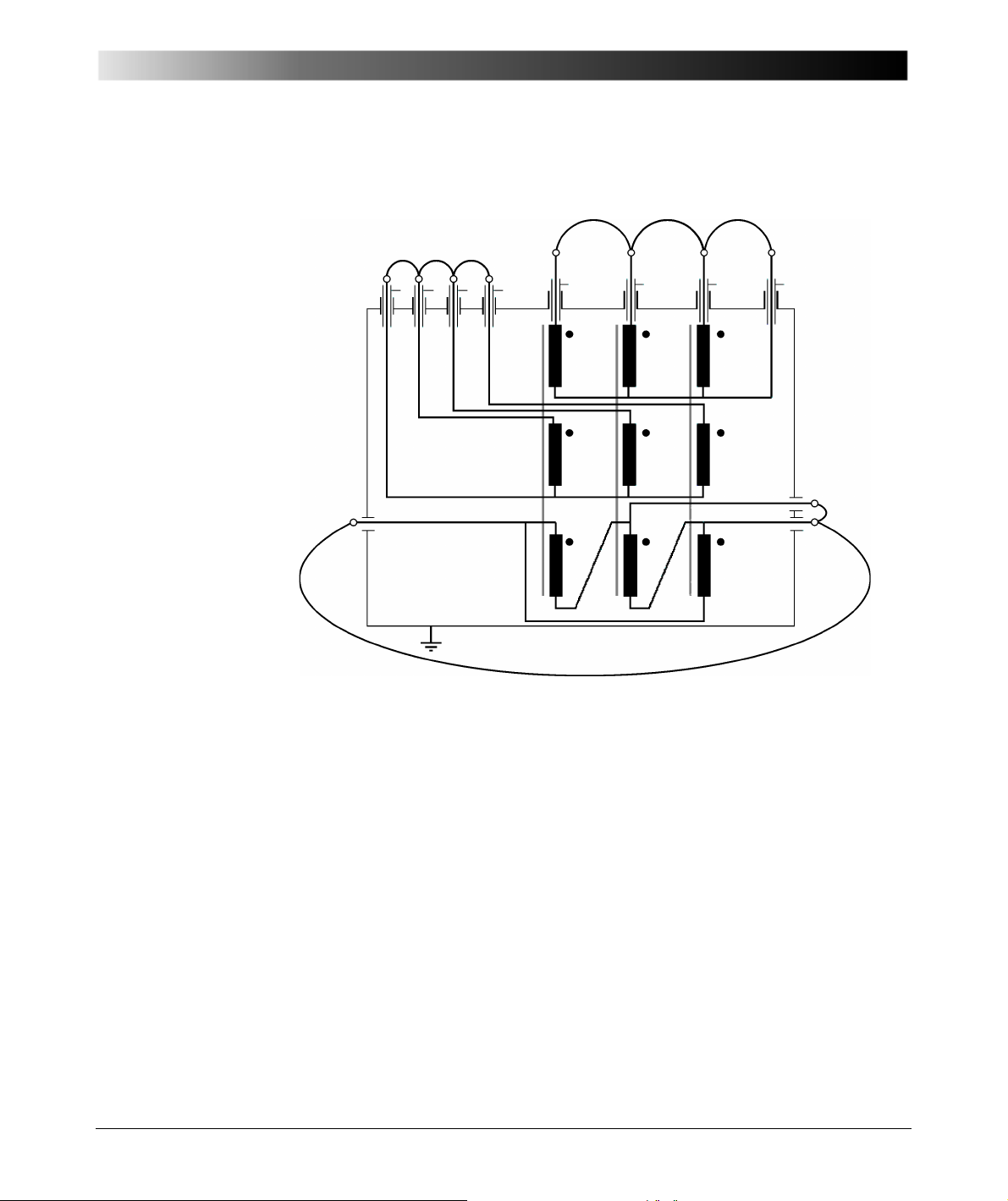
ABC
winding and A, B, C (and Neutral) of tertiary winding have to be connected
by a copper wire (see Figure 6-1).
Figure 6-1 Three-winding transformer with connected winding
• The neutral terminals of all Y-connected windings with outside-connected
Neutral have to be disconnected from ground (tank).
• If the transformer has a tap changer then it should be set to the neutral
position (0 or middle tap).
• Connect the CPC 100 + CP TD1 ground terminal to the transformer's
(substation) ground.
• Connect the high-voltage output of the CP TD1, e.g. to the high-voltage
winding (according to the connection instructions). Touching any parts
71
Page 72

CP TD1 Reference Manual V 1.44
like the bushings and the transformer tank (flashovers) with the
unscreened part of the high-voltage test cable must be avoided.
• Connect the IN A, e.g. to the low-voltage winding, IN B, e.g. to the tertiary
winding (according to the connection instructions).
• Short circuit all bushing CTs.
• Do not make high-voltage tests on transformers under vacuum.
• The test voltage should be chosen with respect to the rated voltage of the
winding.
• All tests should be made with oil temperatures near 20°C. Temperature
corrections can be calculated by using correction curves, but they depend
a great deal on the insulation material, the water content and many other
parameters. This way the correction has limited accuracy.
6.2.1 Three-Winding Transformer
A transformer contains a complicated insulation system. High- and low-voltage
windings have to be insulated to the tank and the core (ground) and against each
other. All these insulation gaps should be checked regularly. Normally in a twowinding power transformer, C-Tan-Delta measurements are made for all
insulation gaps: HV to LV, HV to ground, LV to ground.
72
Page 73
Power Transformers
N (L) B (L)A (L) C (L)
A (H) B (H) C (H) N (H)
Bushing (A) Bushing (C)Bushing (B)
C H(A) C H(C)C H(B)
C H-L (A)
C H-L(C)C H-L (B)
C H-T
(A)
C H-T
(B)
C H-T
(C)
C L-T(A)C L-T(A)
C L-T
(B)
C L-T
(C)
C L(C)
C L(B)
C L(A)
C T(C)
C T(B)
C L(A)
A B C
H
L
T
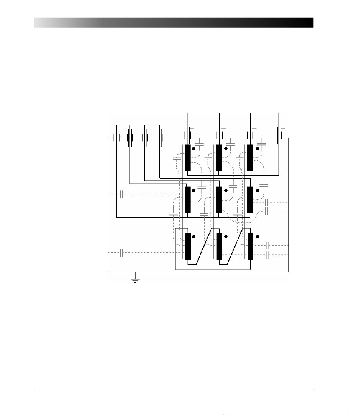
A three-winding transformer is much more complicated so more tests are
necessary to measure all gaps. In Figure 6-2, a complete 3-winding power
transformer is shown. The tertiary winding is not accessible in this case. When
the load is unbalanced, it is necessary for flux compensation in the three limbs
of the core.
Figure 6-2 Three-winding transformer with winding to winding and winding
to ground capacitors
73
Page 74
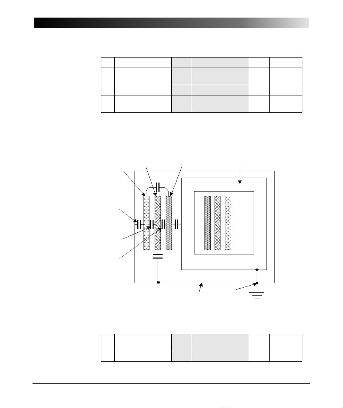
CP TD1 Reference Manual V 1.44
Core
Tank
G
C
L-T
C
H-L
C
H
C
T
C
L
H
LT
A Phase A B Phase B C Phase C
H High-Voltage
winding
C H Cap. H to Ground C H-L Cap. H to
L
L Low-Voltage winding C L Cap. L to Ground C L-T Cap. L to T
T Tertiary winding C T Cap. T to Ground C H-T Cap. H to
T
As shown in Figure 6-2, the three phases of the high-voltage (H), the low-voltage
(L) and the tertiary (T) windings are connected internally in y or delta. This way
only the sum of all three phases can be measured, the single phases can not be
measured separately. Figure 6-3 shows the simplified circuit diagram of the
three-phase transformer of Figure 6-2.
Figure 6-3 Three-phase transformer with winding capacitances
74
H High-Voltage
winding
C H Cap. H to Ground C H-L Cap. H to
L
L Low-Voltage winding C L Cap. L to Ground C L-T Cap. L to T
Page 75
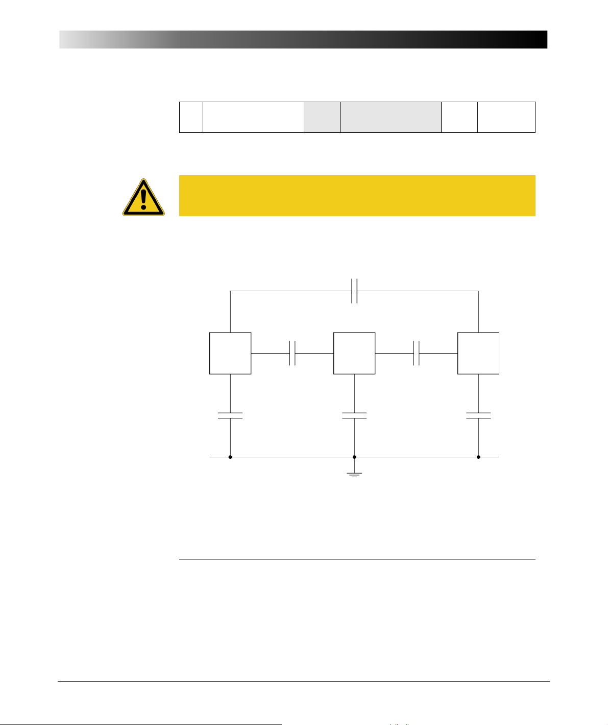
Power Transformers
TERT. LOW HIGH
C
HT
C
LT
C
HL
C
T
C
L
C
H
T Tertiary winding C T Cap. T to Ground C H-T Cap. H to
T
To check the winding insulation completely, it is necessary to measure the
capacitance and the DF of all insulation gaps (in this case six capacitors).
Caution: All phases and the neutral terminal of one winding (H, L and T) have
to be short-circuited. Due to the inductance of the windings resonant effects
may occur and influence the measurement.
In IEEE Std. 62-1995 [3.4] the test procedure is described for transformers with
two and three windings. Figure 6-4 shows the six measurements.
Figure 6-4 Three-winding transformer test according to IEEE 62-1995
Test Mode Energize Ground Guard UST Measure
GST HIGH – LOW, TERT. – C
GST LOW –
GST TERT. – HIGH, LOW – C
Supplementary test for interwinding insulations
H
TERT., HIGH
–C
L
T
75
Page 76

CP TD1 Reference Manual V 1.44
UST HIGH TERT. – LOW C
UST LOW HIGH – TERT. C
UST TERT. LOW – HIGH C
HL
LT
HT
A more detailed test procedure for two- and three- winding transformers can be
found in [3.6]. This test procedure is included in the appendix and is now used
as an example to show the test preparation of a 3-winding transformer test with
76
Page 77
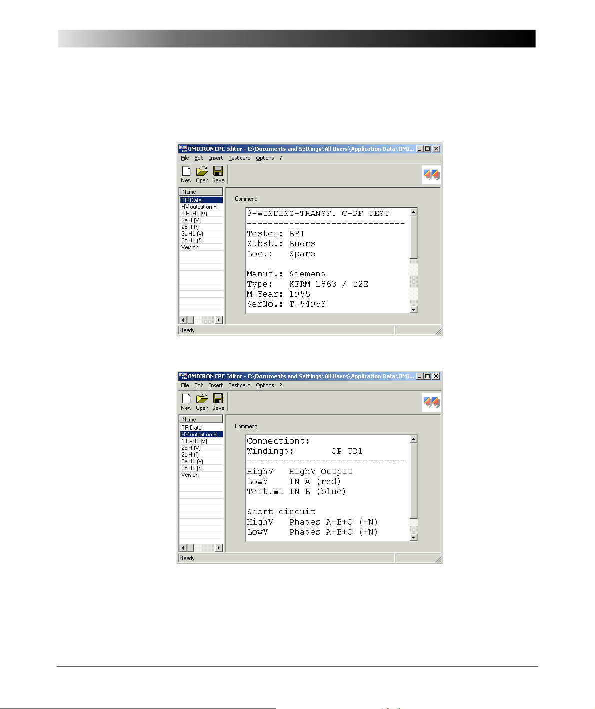
Power Transformers
the CPC Editor. Due to the high amount of measuring data, the test is split into
three single test files. The first file contains the tests with high-voltage winding
connected to the CP TD1 high-voltage output:
Figure 6-5 Input of transformer data
Figure 6-6 Instruction about test lead connections
77
Page 78
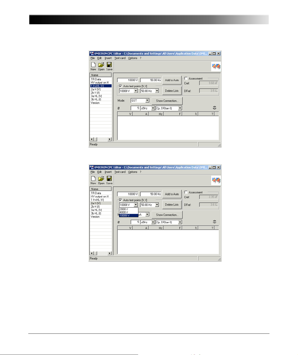
CP TD1 Reference Manual V 1.44
Figure 6-7 Measurement of C H and C H-L in GST g-B mode
78
Figure 6-8 Voltage-scan of high-voltage windings to tank and core (GST
gA+B)
Page 79
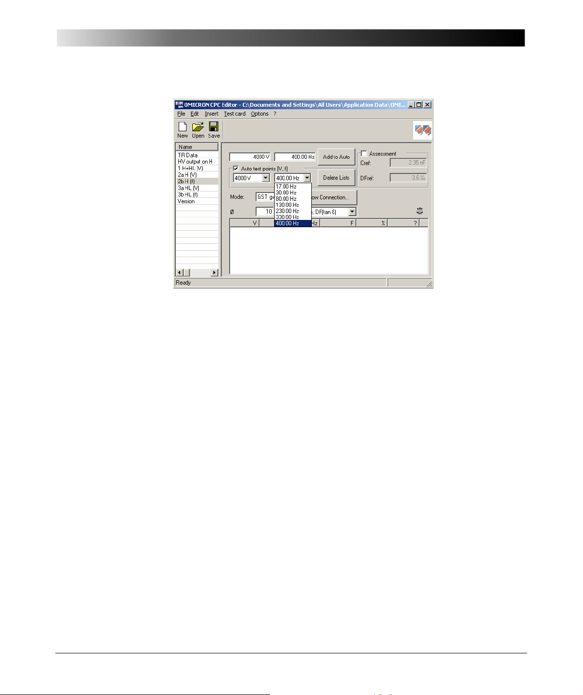
Power Transformers
Figure 6-9 Frequency-scan of high-voltage windings to tank and core (GST
gA+B)
The other tests for H-L are prepared analog to the examples.
79
Page 80
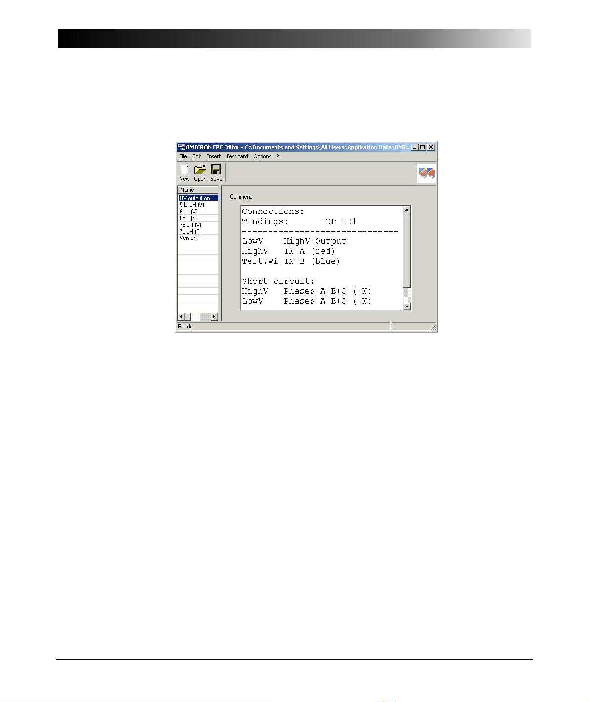
CP TD1 Reference Manual V 1.44
A second test file contains the tests with the low-voltage winding connected to
the high-voltage output of the CP TD1. Figure 6-10 shows the first screen with
the connection instructions.
Figure 6-10 Connection instructions for the tests with energized low-voltage
winding
80
Page 81
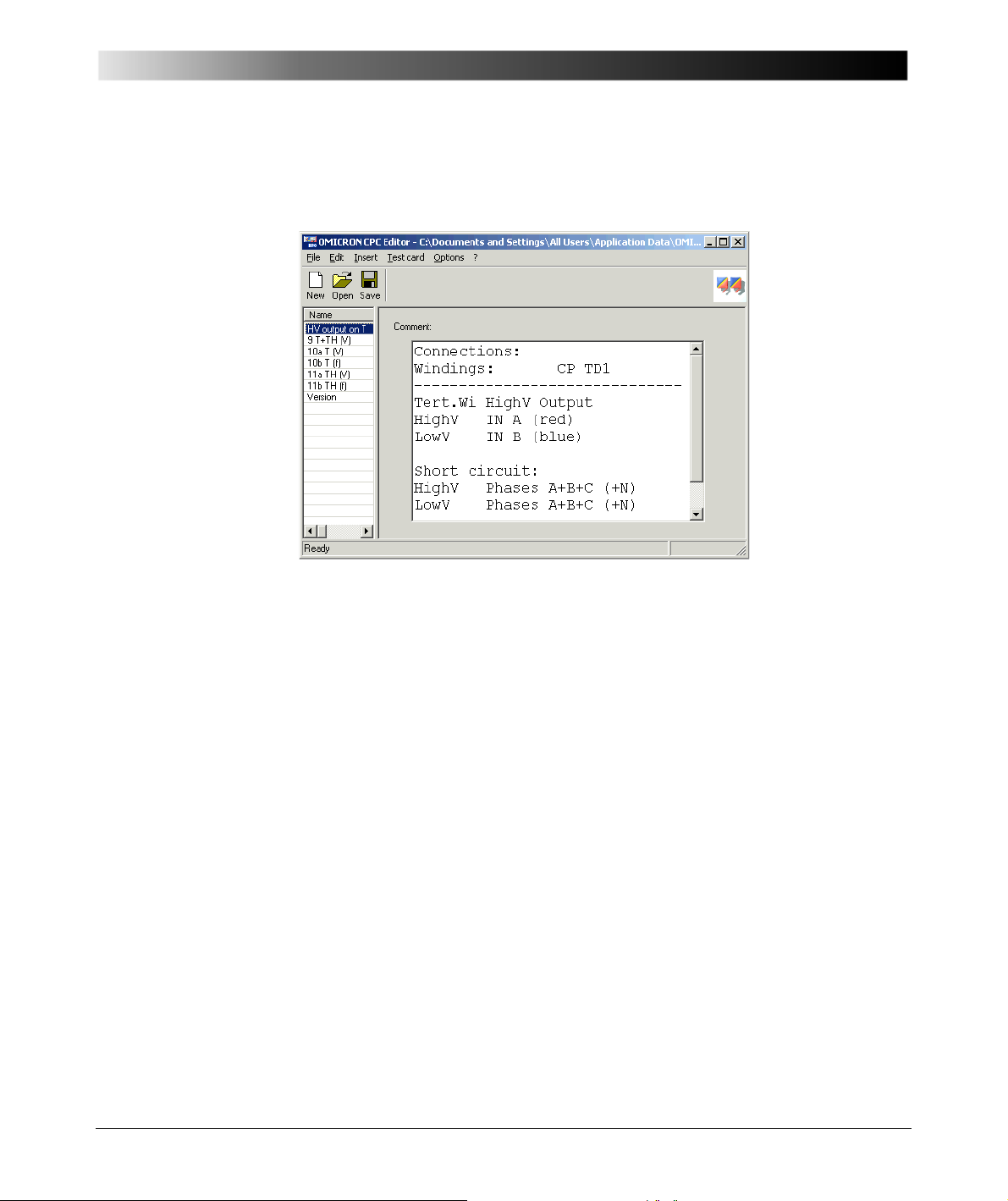
Power Transformers
A third test file is used for the tests with the tertiary winding connected to the
CP TD1 high-voltage output. 6-11 shows the connection instructions for the
tests with energized tertiary winding.
Figure 6-11 Connection instructions for the tests with energized tertiary
winding
81
Page 82
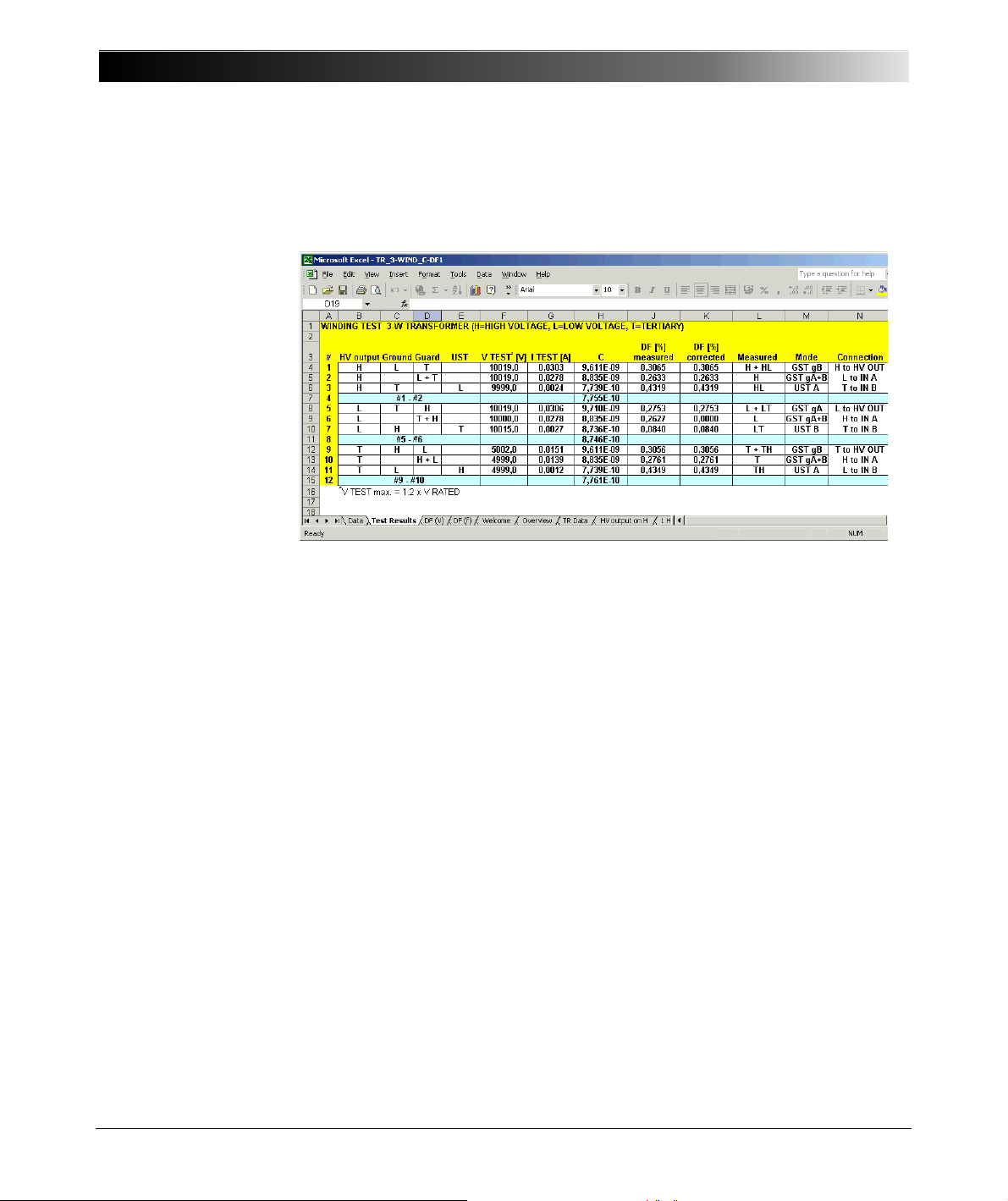
CP TD1 Reference Manual V 1.44
The prepared tests are uploaded to the CPC 100 as xml files without results.
After the test is done, this xml file with the results is downloaded to the computer
and loaded into Microsoft Excel with the OMICRON CPC 100 File Loader (the
complete test files are included on the CD-ROM).
Figure 6-12 10 kV results for a three-winding transformer (50 Hz)
Figure 6-12 shows the results for 10 kV:
•1: H+HL
•2: H
•3: HL
• 5: L+LT
•6: L
•7: LT
•9: T+TH
• 10: T
• 11: TH
In line 4, the difference of the capacity values of test 1 - test 2 is calculated so it
can be compared to test 3. In lines 8 and 12, the differences of lines 5-6 and 9-10
are calculated to also enable a comparison to tests 7 and 11. This way the
reliability of the measured values can be checked. For the tertiary winding, the
test voltage was reduced to 5 kV due to the lower rated voltage of this winding.
A voltage scan measurement is shown in Figure 6-13, a frequency scan in
Figure 6-14.
82
Page 83
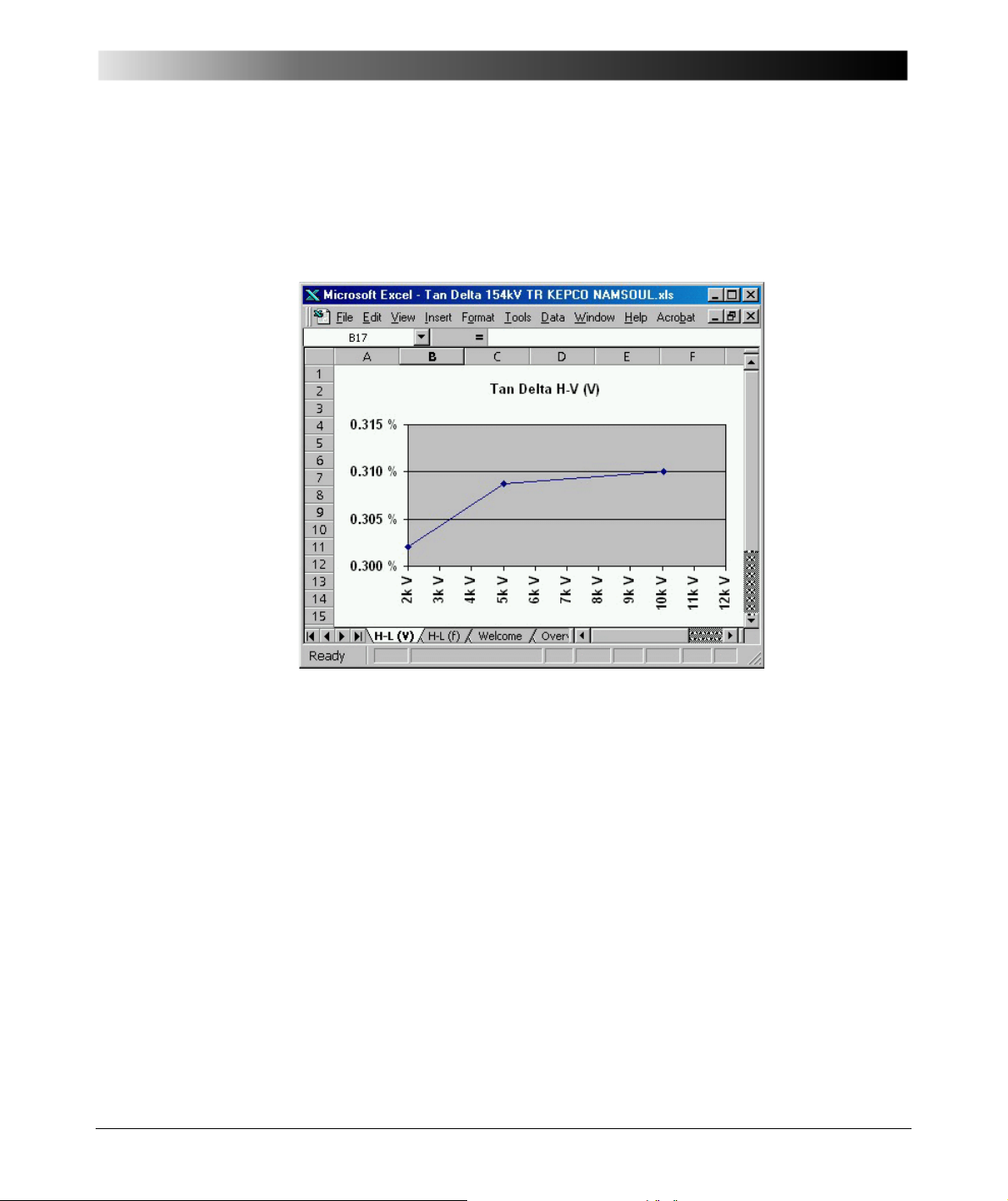
Power Transformers
Voltage and frequency scans enable additional information about the insulation
quality. They should be saved as "fingerprint" for future measurements. For all
the described measurements only three different connections of the test leads
are necessary. Preparing the test in the office by utilizing the CPC Editor, the
testing time on-site can be reduced to a minimum.
Figure 6-13 Voltage-scan for H-L (V) (50 Hz)
83
Page 84
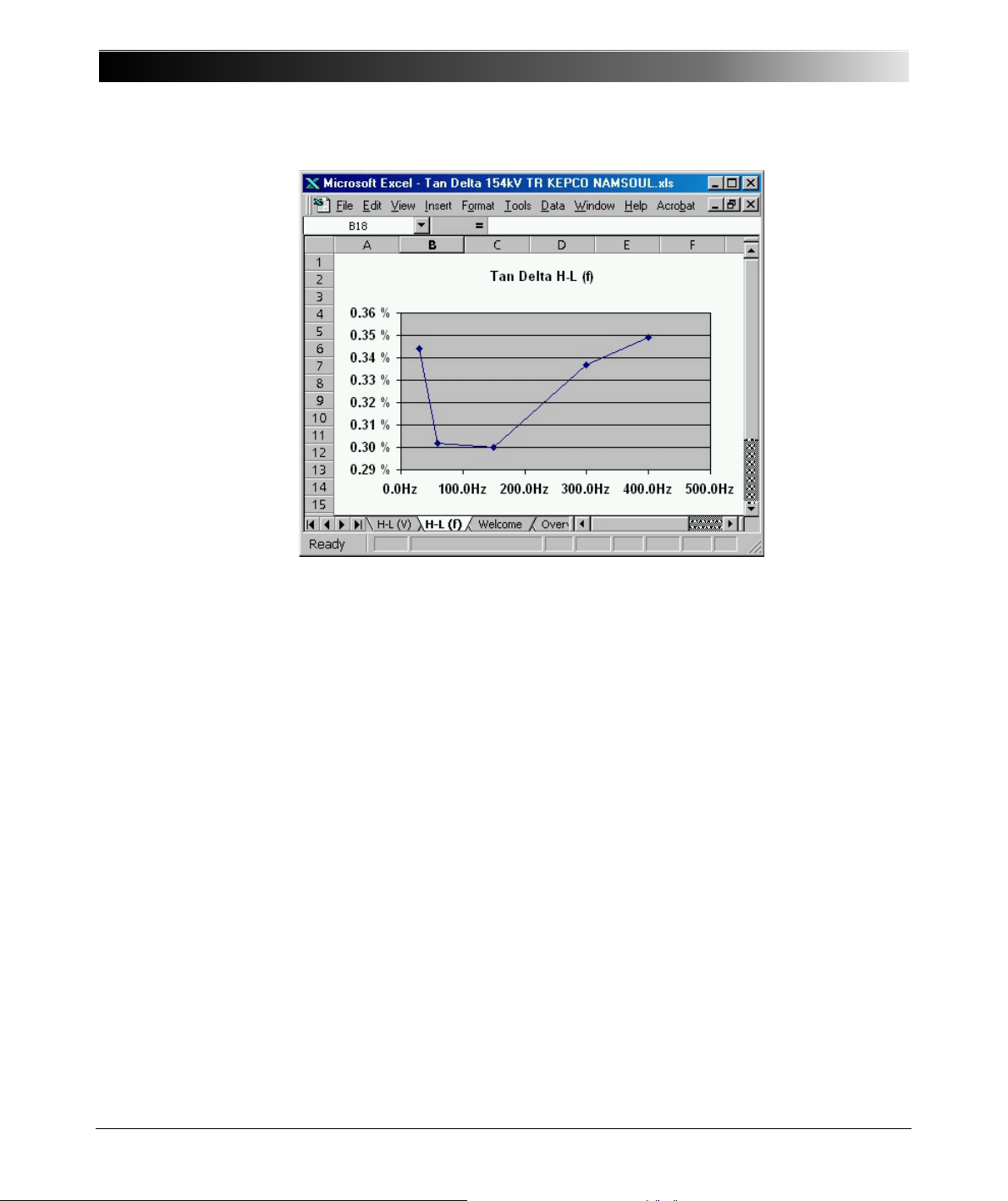
CP TD1 Reference Manual V 1.44
Figure 6-14 Frequency scan for H-L (f) (5 kV)
84
Page 85
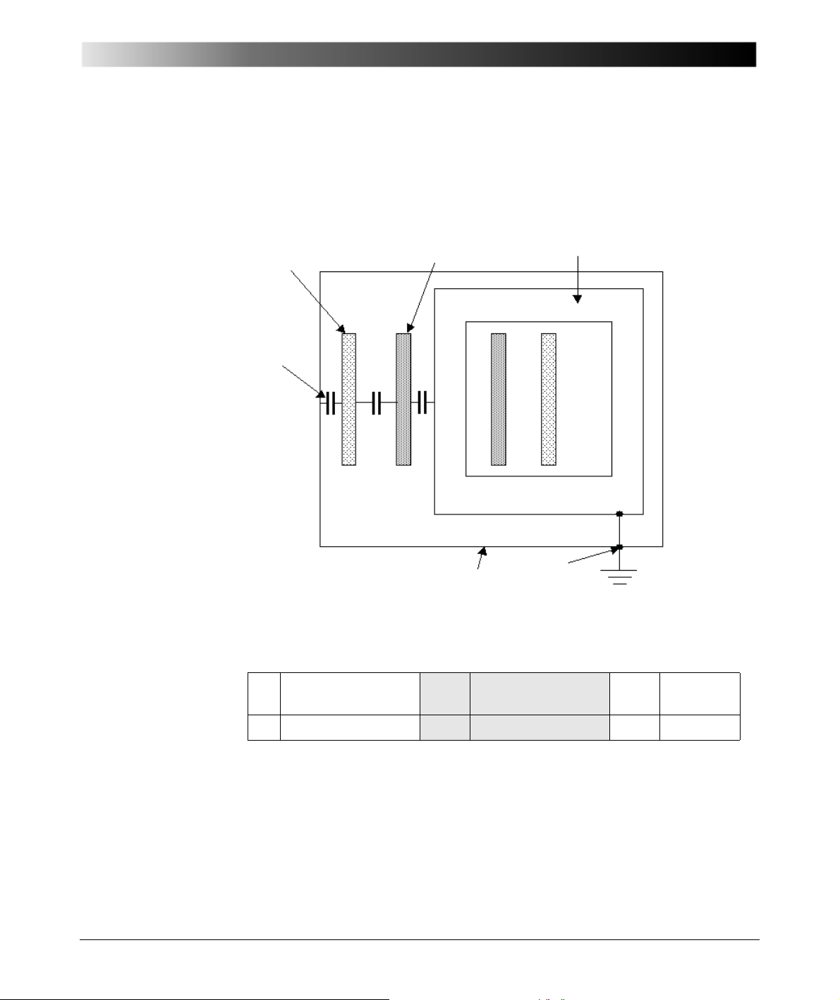
6.2.2 Two-Winding Transformer
Core
Tank
G
H
L
C
H-L
C
H
C
L
The test of two-winding transformers is easier than the described test procedure
for transformers with three windings. Figure 6-15 shows the simplified circuit
diagram of a two-winding transformer.
Power Transformers
Figure 6-15 Two-winding transformer with winding capacitances
H High-Voltage
winding
C H Cap. H to Ground C H-L Cap. H to
L
L Low-Voltage winding C L Cap. L to Ground C L-T Cap. L to T
85
Page 86
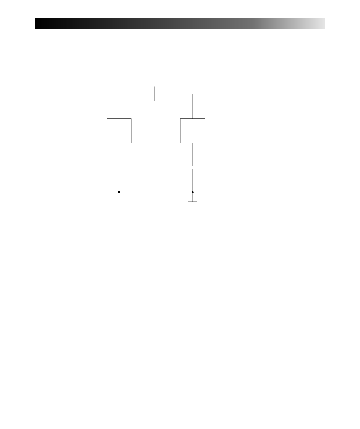
CP TD1 Reference Manual V 1.44
LOW HIGH
C
HL
C
L
C
H
In Figure 6-16, the test procedure for a two-winding transformer is shown,
according to IEEE 62 1995 [3.4].
Figure 6-16 Two-winding transformer test according to IEEE 62-1995
Test Mode Energize Ground Guard UST Measure
GST HIGH – LOW – C
GST LOW – HIGH – C
Alternative test for C
HL
UST HIGH – – LOW C
UST LOW – – HIGH C
H
L
HL
HL
86
Page 87
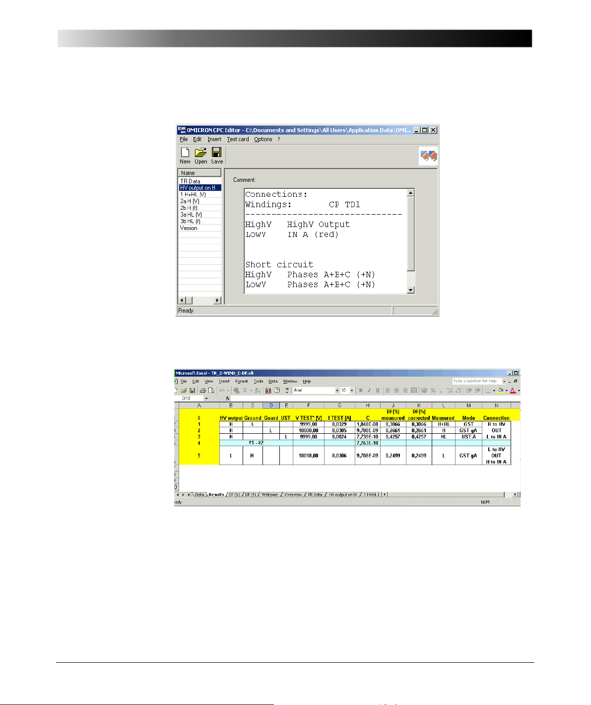
Power Transformers
Figures 6-17 and 6-18 show the preparation with the CPC Editor and the test
results in MS Excel format.
Figure 6-17 Two-winding transformer test preparation with CPC Editor
Figure 6-18 10 kV results for a two-winding transformer (50 Hz)
6.2.3 Auto-Transformer
The auto-transformer has only one winding with a tap for the low-voltage output.
Only one measurement is made of the winding to tank and core. All high-voltage
and low-voltage terminals are connected together as they are building the highvoltage electrode of the capacity.
87
Page 88

CP TD1 Reference Manual V 1.44
6.2.4 Reactors
Similar to the auto-transformers, reactors also normally have only one winding.
Often the low-voltage ends of the three phases are connected outside the tank
to the Neutral. In this case we have 2 bushings per phase, which have to be
connected for the DF test. We can measure all combinations: phase to phase
and phase to tank (ground).
6.3 Transformer High-Voltage Bushing Tests
High-voltage bushings are generally used in power transformers, but also in
circuit breakers and in other electrical apparatus. Therefore, the test of bushings
is described in chapter 7 ”Capacitance and DF Measurement on High-Voltage
Bushings” on page 91.
6.4 Interpretation of Measurement Results
Initial tests on new transformers when it arrives from the manufacturer
determines the presence of manufacturing defects or transport damage, and
also provides "fingerprint" test values for future comparisons. Periodic tests
during the life cycle of the transformer can indicate that the insulation is aging
normally or rapidly.
6.4.1 Dissipation Factor Measurement
Environmental Conditions
As already mentioned in chapter 5 ”Capacitance and Dissipation Factor
Measurement” on page 39, environmental factors can influence DF
measurements greatly. Therefore it is important to record the ambient conditions
at the time of testing when comparing test results. The tests should be made with
oil temperatures near 20°C. Temperature corrections can be calculated, utilizing
correction curves, but they depend very much on the insulation material, the
water content and a lot of other parameters. This way the correction has limited
accuracy. Testing at temperatures below freezing should be avoided, since the
measurement results are not reliable. If the water in the insulation is frozen to
ice, it may not be detected by DF testing.
Other factors like relative humidity and the general weather conditions should be
recorded in the test report for future reference.
88
Page 89
Power Transformers
For oil paper insulation, the range of the DF values for new and aged
transformers are published in some standards like [3.4] and in other literature
[3.1], [3.2]. In IEEE Std. 62-1995 [3.1] the following limits for DF values are
given:
Table 6-4 DF values for oil paper insulation
Condition of insulation
Transformer Good May be accept-
able
New DF < 0.5% - -
Service-aged DF < 0.5% 0.5% < DF < 1% DF > 1%
All values measured at 20 °C
It is always better to measure the values regularly and save them for comparison
to tests in the past and in the future. In this way, trends can be observed and the
evaluation of results is of much higher quality.
Should be investi-
gated
6.4.2 Capacitance Measurement
The capacitance of the insulation gaps between the windings to each other and
to ground depends mainly on the geometry of the winding. Windings may be
deformed after transport of the transformer or nearby through faults with high
currents. Changes in capacitance serve as an excellent indicator of winding
movement and structural problems (displaced wedging, buckling etc.). If a
winding damage is suspected then the capacitance measurement should be
supplemented by a leakage reactance measurement. A separate test can be
done for each phase with this measurement technique. Therefore this method is
more sensitive to small changes in one phase.
6.5 References
[3.1] US Bureau of Reclamation: "Maintenance of liquid insulation
mineral oils and Askarels", Facility instructions, standards and
techniques - Vol. 3-5, 1992
[3.2] Möllmann, A., Lütge, H.: IEC / VDE Standards für flüssige
Isolierstoffe zur Diagnostik von Transformatoren und Wandlern,
ETG-Fachbericht "Diagnostik elektrischer Betriebsmittel", VDEVerlag GmbH Berlin 2002, S. 205-210
89
Page 90

CP TD1 Reference Manual V 1.44
[3.3] US Bureau of Reclamation: "Transformer Maintenance",
Facility instructions, standards and techniques - Vol. 3-30, 2000
[3.4] ANSI Standard 62-1995: "IEEE Guide for Diagnostic Field
testing of Electric Power Apparatus - Part 1: Oil Filled Power
Transformers, Regulators, and Reactors", IEEE New York,
1995
[3.5] US Bureau of Reclamation: "Transformer Diagnostics", Facility
instructions, standards and techniques - Vol. 3-31, 2003
[3.6] IEEE Standard C57.12.90: "IEEE Standard Test Code for
Liquid-Immersed Distribution, Power, and Regulating
Transformers", IEEE New York, 1995
90
Page 91
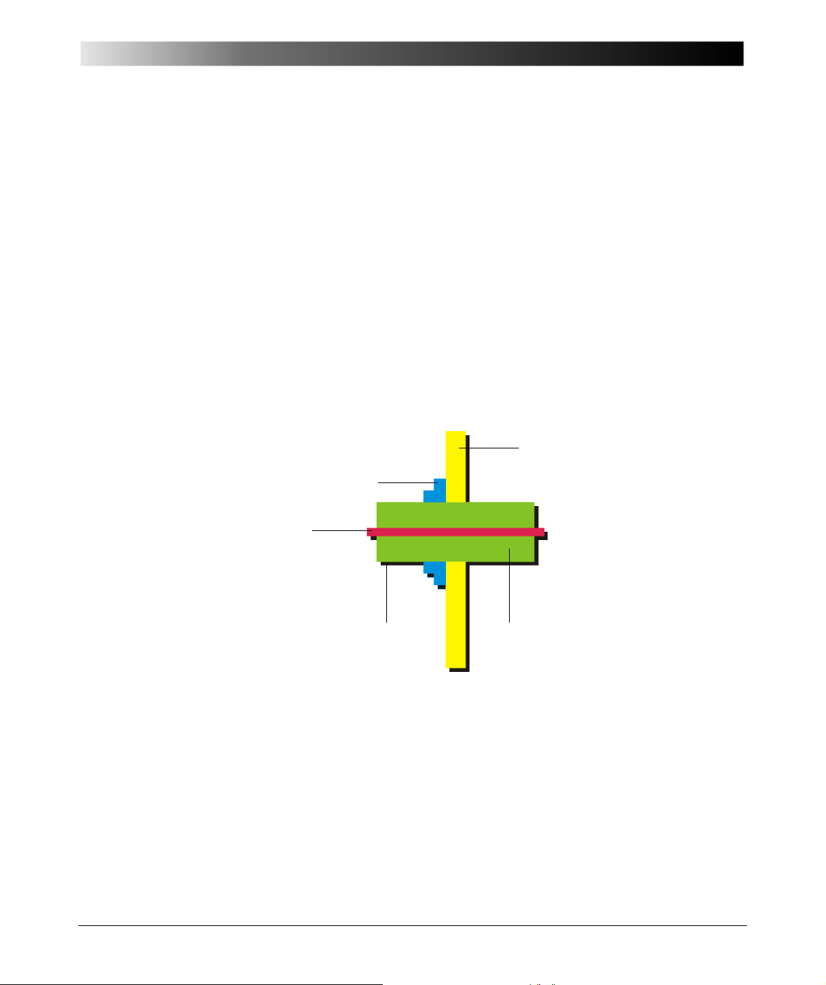
Capacitance and DF Measurement on High-Voltage Bushings
Wall,tank
Main insulation:
• Solid
Ceramic, cast insulation,
synthetic resin bonded paper,
resin impregnated paper,
composite
• Liquid: oil
•Gas
Ambient:
•Air
indoor
outdoor
•Oil
•Gas
Conductor
Flange
7 Capacitance and DF Measurement on
High-Voltage Bushings
7.1 Introduction
High-voltage bushings are essential parts of power transformers, circuit
breakers and of other power apparatus. More than 10% of all transformer
failures are caused by defective bushings [4.2]. Although the price for a bushing
is low compared to the costs of a complete transformer, a bushing failure can
damage a transformer completely. A regular capacitance and DF measurement
is highly recommended.
7.2 Types of Bushings
Figure 7-1 Principle of bushings
91
Page 92
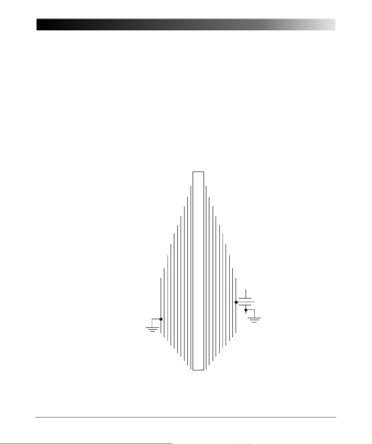
CP TD1 Reference Manual V 1.44
Tap electrode
grounded
layer/flange
Grounded
layer/flange
C
A
C
B
C
C
C
D
C
E
C
F
C
G
C
H
C
I
C
K
C
J
Testing and maintaining high-voltage bushings are essential for continued
successful operation of transformers and circuit breakers. Power outages may
occur as the result of a bushing failure. High-voltage bushings used on
transformers and breakers exist in many forms, including:
Condenser
This type is most frequently used for high-voltage bushings and it is therefore
the main one focused in this guide. Cylindrical conducting layers are arranged
coaxially with the conductor within the insulating material. The length and
diameter of the cylinders are designed to control the distribution of the electric
field in and over the outer surface of the bushing. The partial capacities are
switched in series and the voltage drops across the capacities is nearly equal to
each other (Figures 7-2 and 7-3) [4.1].
92
Figure 7-2 Condenser bushing design [4.1]
Page 93
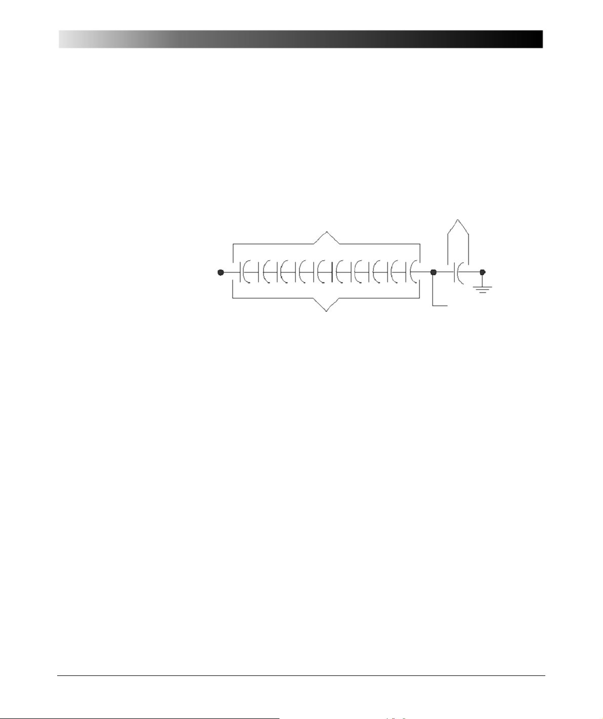
Capacitance and DF Measurement on High-Voltage Bushings
CA=CB=CC=CD=CE=CF=CG=CH=CI=C
J
V1 = V2 = V3 = V4 = V5 = V6 = V7 = V8 = V9 = V
10
C
1
C
2
C
K
Tap electrode
(normally grounded)
Grounded
layer/flange
Center
conductor
Line-to-ground system voltage
Main insulation
Tap insulation
Notes:
– Equal capacitances, C
center conductor to the grounded condenser layer and flange.
– The tap electrode is normally grounded in service except for certain designs and bushings used
with potential device.
– For bushings with potential taps, the C
power-factor tap, C
through CJ, procedure equal distribution of voltage from the energized
A
capacitance is much greater than C1. For bushings with
and C2 capacitances may be same order of magnitude.
1
2
Figure 7-3 Condenser bushing circuit diagram [4.1]
Condenser bushings may have:
• "Resin-Bonded Paper insulation (RBP)
• "Resin-Impregnated Paper insulation (RIP)
• "Oil-Impregnated Paper insulation (OIP)
Composite
A bushing where the insulation consists of two or more coaxial layers consisting
of different insulating materials.
Compound-filled
A bushing where the space between the major insulation or conductor, if no
major insulation is used, and the inside surface of a protective weather casing
(usually porcelain) is filled with a compound that contains insulating properties.
Dry or unfilled
A bushing consisting of a porcelain tube with no filler in the space between the
shell and the conductor. These are usually rated 25 kilovolts and below.
93
Page 94

CP TD1 Reference Manual V 1.44
Oil-filled
A bushing where the space between the major insulation or the conductor, and
the inside surface of a protective weather casing is filled with insulating oil.
Oil-immersed
A bushing composed of major insulators that are totally immersed in a bath of
insulating oil.
Oil-impregnated paper-insulated
A bushing where the internal structure is made of cellulose material impregnated
with oil.
Resin-bonded paper-insulated
A bushing where cellulose material bonded with resin provides the major
insulation.
Solid, ceramic
A bushing where a ceramic or other similar material provides the major
insulation.
Gas insulated
A bushing that contains compressed gas like SF6 or mixtures of SF6 with other
gasses i.e. N2. This type is frequently used for circuit breaker bushings.
7.3 Bushing Troubles
About 90 percent of all preventable bushing failures are caused by moisture
entering the bushing through leaky gaskets or other openings. Periodic
inspection and diagnostic measurements can prevent most outages due to
bushing failures. High-voltage bushings may explode with considerable violence
and cause extensive damages to adjacent equipment. Flashovers may be
caused by deposits of dirt on the bushings, particularly in areas where there are
contaminants such as salts or conducting dusts in the air. These deposits should
be removed by periodic cleaning. In [4.3] bushings faults, possible reasons and
methods of detection are explained (Table 7-1).
94
Page 95
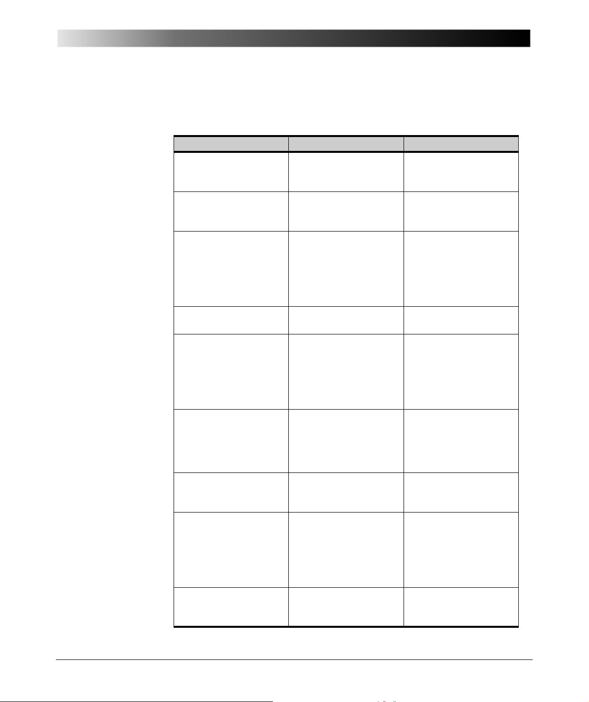
Capacitance and DF Measurement on High-Voltage Bushings
Table 7-1 Bushing faults, part 1 [4.3]
Failure Possible results Methods of detection
Cracked porcelain Moisture enters;
Oil and/or gas leaks;
Filler leaks out
Deterioration of
cemented joints
Gasket leaks Moisture enters;
Moisture in insulation Moisture enters Power factor test;
Solder seal leak Moisture enters;
Broken connection
between ground sleeve
and flange
Voids in compound Internal corona Visual inspection;
Displaced grading shield Internal sparking
Electrical flashover Cracked or broken
Moisture enters;
Oil and/or gas leaks;
Filler leaks out
Oil and/or gas leaks;
Filler leaks out
Filler leaks out
Sparking in apparatus
tank or within bushing;
Discolored oil
discolors oil
porcelain;
Complete failure
Visual inspection;
Power factor test;
Hot-collar test
Visual inspection;
Power factor test;
Hot-collar test
Visual inspection;
Power factor test;
Hot-collar test;
Hot-wire test for
moisture;
Insulation resistance
Hot-collar test
Visual inspection;
Power factor test;
Hot-collar test;
Hot-wire test for
moisture;
Leak detector
Power factor test;
Uncharacteristic odor;
Dissolved gas-in-oil
analysis (DGA);
Thermographic scanning
Power factor test;
Hot-collar test
Hot-collar test;
Uncharacteristic odor;
Thermographic
scanning;
Dissolved gas-in-oil
analysis (DGA)
Visual inspection;
Hot-collar test
95
Page 96
CP TD1 Reference Manual V 1.44
Table 7-1 Bushing faults, part 1 [4.3]
Failure Possible results Methods of detection
Lightning Cracked or broken
Corona Internal breakdown;
Short-circuited
condenser sections
Darkened oil Radio interference;
porcelain;
Complete failure
Radio interference;
Treeing along surface of
paper or internal
surfaces
Increased capacitance;
Reduced voltage at
capacitance tap terminal;
Adds internal stress to
insulation
Poor test results
Visual inspection;
Test lightning arresters
Power factor test;
Hot-collar test;
Hot wire test;
Radio-influence voltage
(RIV) test;
Thermographic
scanning;
Dissolved gas-in-oil
analysis (DGA)
Power factor test;
Voltage test at
capacitance tap;
Capacitance test;
Thermographic
scanning;
Dissolved gas-in-oil
analysis (DGA)
Power factor test;
Hot-collar test
7.4 Capacitance and DF Measurement on High-Voltage
Bushings
The dissipation factor test is the most effective known field test procedure for the
early detection of bushing contamination and deterioration. It also measures
alternating (AC) test current, which is directly proportional to bushing
capacitance.
Bushing dissipation factor and capacitance should be measured when a bushing
is first installed and also one year after installation. After these initial
measurements, bushing power or dissipation factor and capacitance should be
measured at regular intervals (3 to 5 years typically). The measured values
should be compared with previous tests and nameplate values.
96
Page 97

Capacitance and DF Measurement on High-Voltage Bushings
Note: Large variations in temperature significantly affect dissipation factor
readings on certain types of bushings. For comparative purposes, readings
should be taken at the same temperature. Corrections should be applied before
comparing readings taken at different temperatures.
Bushings may be tested by one or more of four different methods, depending
upon the type of bushing and the dissipation factor test set available. For more
detailed instructions on this test procedure, see the dissipation factor test set
instruction book from the appropriate manufacturer. The four test methods are
described as follows:
7.5 Ungrounded Specimen Test (UST)
This test measures the insulation between the center conductor and the
capacitance tap, the dissipation factor tap, and/or ungrounded flange of a
bushing. This test may be applied to any bushing in or out of the apparatus that
is either equipped with capacitance or dissipation factor taps, or with the flange
that can be isolated from the grounded tank in which the bushing is installed. The
insulation resistance between the taps or insulated flanges and ground should
be 0.5 M or greater. While in this case anything that is attached to the bushing
would also be energized, only the insulation of the bushing between the center
conductor and the ungrounded tap or flange would be measured. In the case of
bushings equipped with capacitance taps, a supplementary test should always
97
Page 98
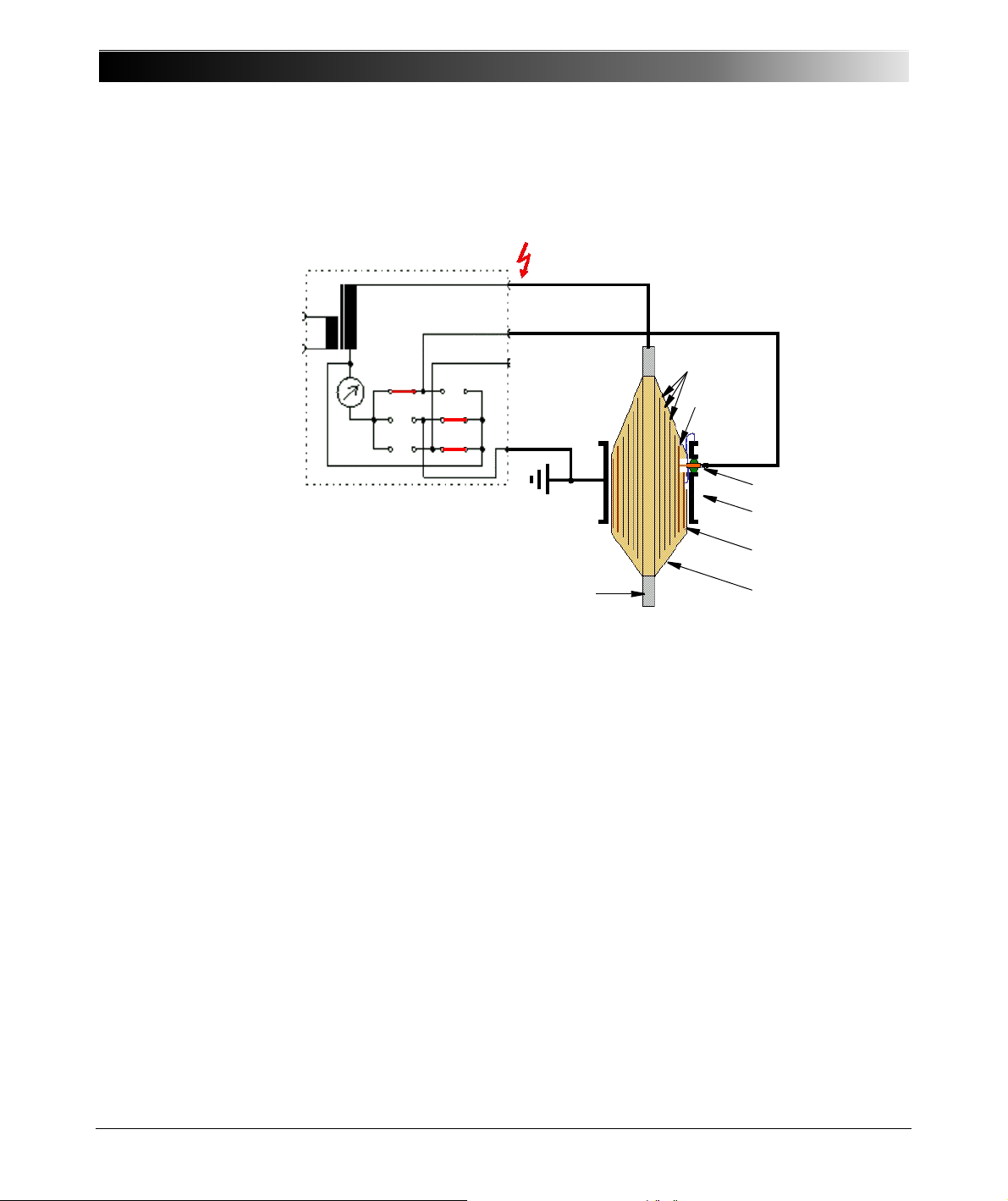
CP TD1 Reference Manual V 1.44
UST-A
Equalizers
C1 Layer
Voltage tap
Mounting flange
C2 layer (always
grounded to flange)
Paper insulation
IN A
IN B
Main conductor
be made on the insulation between the tap and the flange. Most manufacturers
list the UST dissipation factor and capacitance values on the bushing
nameplate.
98
Figure 7-4 UST bushing test (C1)
When bushings with capacitance or potential taps rated at 110 kV and above are
tested by the ungrounded test specimen method, a separate dissipation factor
test on the tap insulation should be performed as well.
For capacitance or potential taps, tests are performed at a voltage between 500
and 1,000 volts. The tap is energized with the bushing center conductor and
flange grounded. The dissipation factor of a capacitance or potential tap will
generally be of the order of 1.0 percent or less. Routine tap insulation tests are
not normally recommended for bushings that are rated 69 kilovolts and below
with dissipation factor taps. However, a dissipation factor test of the tap
insulation should be performed when UST results are questionable or visual
examination indicates the dissipation factor tap's condition is questionable. This
test procedure is similar to that used earlier for capacitance taps. In such cases,
the maximum permissible test potentials should be limited to those given in the
Page 99
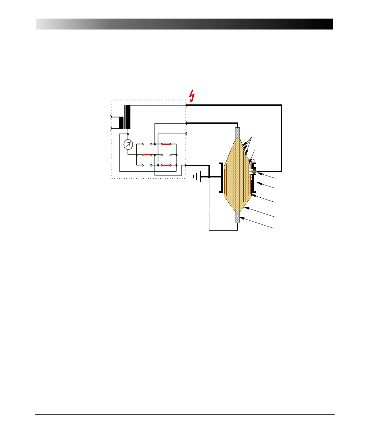
Capacitance and DF Measurement on High-Voltage Bushings
GST g A+B
Equalizers
C1 Layer
Voltage tap
Mounting flange
C2 layer (always
grounded to flange)
Paper insulation
Main conductor
IN A
IN B
appendix or as recommended by the bushing manufacturer. The dissipation
factor value of the dissipation factor tap insulation for most of the bushings
discussed earlier is generally in the order of 1.0 percent or less.
7.6 Grounded Specimen Test (GST)
7.7 Hot Collar Test
Figure 7-5 GST bushing test (C2)
This test measures the quality of the insulation between the current carrying or
center conductor and the mounting flange of a bushing. This test is conducted
on bushings that have been removed from equipment, bushings connected to
de-energized equipment, spare bushings, or bushings that have been isolated
from connected windings and interrupters. The test is performed by energizing
the bushing conductor and grounding the flange.
This test measures the condition of a specific small section of bushing insulation
between an area of the upper porcelain rain shed and the current carrying or
center conductor. The test is performed by energizing one or more electrodes
placed around the bushing porcelain with the bushing center conductor
grounded. This test is used to supplement the three previous tests. It is also
99
Page 100
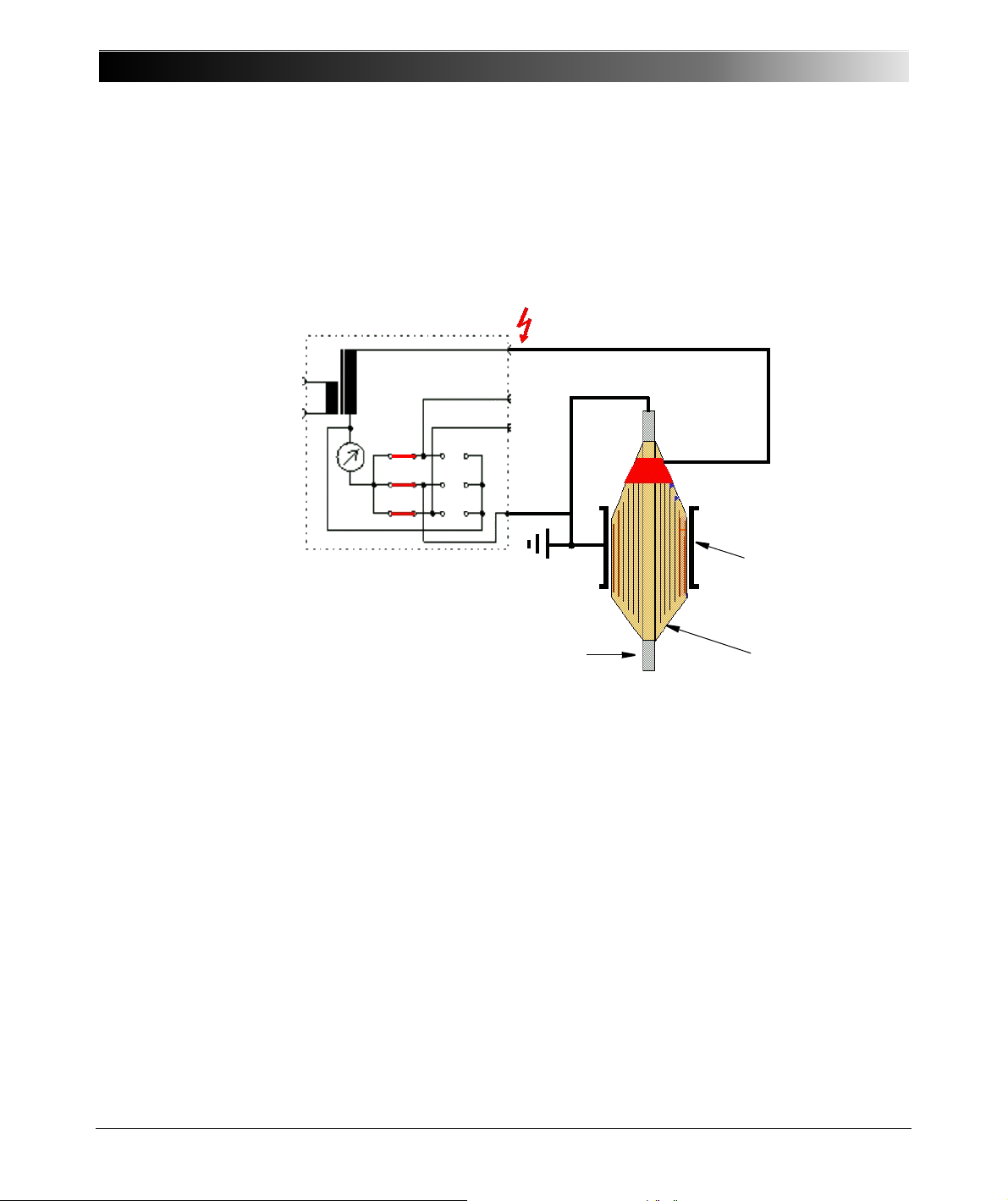
CP TD1 Reference Manual V 1.44
Mounting flange
Paper insulation
Main conductor
GST
IN A
IN B
used to test bushings in apparatus when the three tests are either inapplicable
or impractical, such as, with SF6 bushings. Perform a hot-collar test at every
third skirt on SF6 bushings. Hot-collar tests are effective in locating cracks in
porcelain, deterioration, or contamination of insulation in the upper section of a
bushing, low compound or liquid level, or voids in compound often before such
defects are noticeable with the previous tests.
100
Figure 7-6 Bushing "hot collar" test
In tables of the appendix, typical dissipation factors and dissipation factor the
manufacturers initially published limits. However, the typical or initial dissipation
factor of many bushings is listed on the nameplate. In such cases, field
measurement, particularly UST, should compare with the nameplate dissipation
factors. In general, any bushing that exhibits a history of continuing increase in
dissipation factor should be questioned and scheduled for removal from service.
Measured dissipation factor values should be temperature corrected to 20°C
before being compared with reference values which are measured at 20°C.
Temperature correction factors are average values at best, and therefore,
subject to some error. The magnitude of error is minimized if tests are performed
at temperatures near the reference temperature of 20°C. If questionable
dissipation factors are recorded at relatively high temperatures then the
bushings should not be condemned until it has been allowed to cool down to
near 20°C and repeat tests have been performed. This also applies to bushings
 Loading...