

Page 1
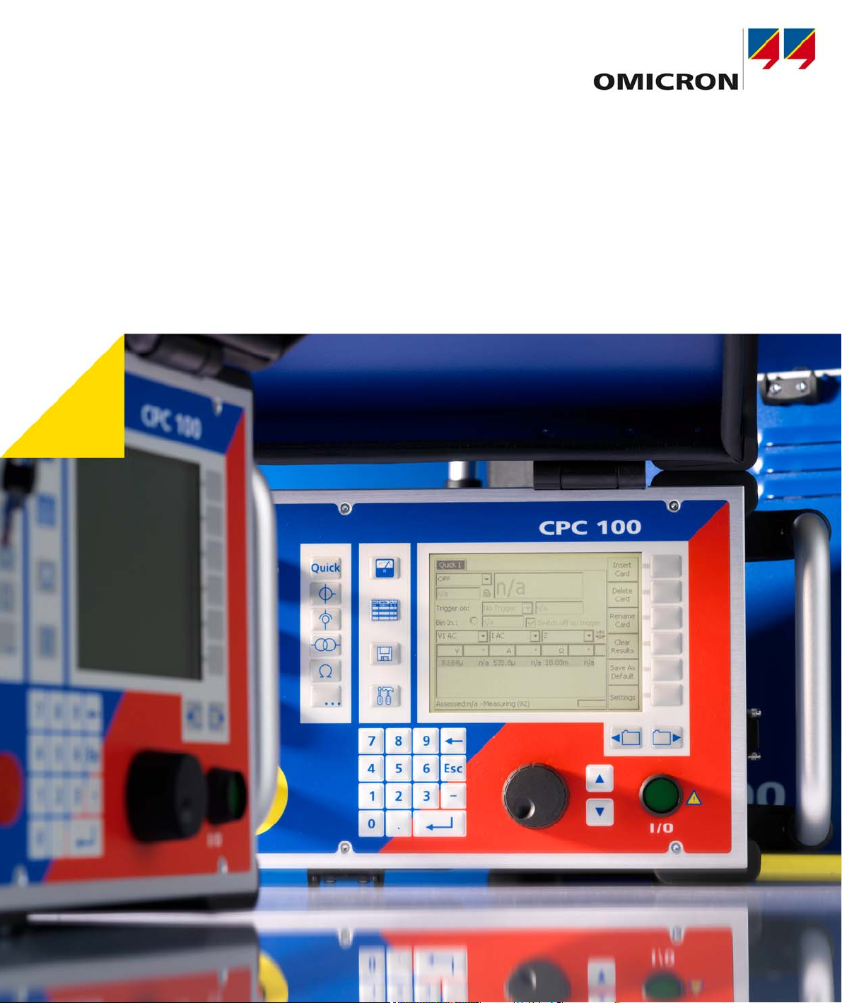
CPC 100
Reference Manual
Page 2

CPC 100 V 1.44
Article Number: VESD0600 - Manual Version: CPC100.AE.10
With regard to the functionality of the CPC 100 software this manual refers to the version V1.44.
© OMICRON electronics 2010. All rights reserved.
This manual is a publication of OMICRON electronics GmbH.
All rights including translation reserved. Reproduction of any kind, for example, photocopying,
microfilming, optical character recognition and/or storage in electronic data processing systems,
requires the explicit consent of OMICRON electronics. Reprinting, wholly or in part, is not permitted.
The product information, specifications, and technical data embodied in this manual represent the
technical status at the time of writing and are subject to change without prior notice.
We have done our best to ensure that the information given in this manual is useful, accurate and
entirely reliable. However, OMICRON electronics does not assume responsibility for any inaccuracies
which may be present.
The user is responsible for every application that makes use of an OMICRON product.
OMICRON electronics translates this manual from the source language English into a number of other
languages. Any translation of this manual is done for local requirements, and in the event of a dispute
between the English and a non-English version, the English version of this manual shall govern.
Page 3

Copyright Information
The OMICRON Bootloader software
The OMICRON Bootloader software includes software parts developed by:
• Intel Corporation (IXP400 SW Release version 2.3)
• Intrinsyc Software (Intrinsyc Bootloader)
• Swedish Institute of Computer Science, Adam Dunkels (lwIP TCP/IP stack)
• Mark Adler (puff - decompress the deflate data format)
• Jean-loup Gailly and Mark Adler ("zlib" general purpose compression library)
The following copyright notices reproduce entirely the copyright notices provided by the source code
owners.
IXP400 SW Release version 2.3
Copyright (c) 2001-2005, Intel Corporation. All rights reserved.
Redistribution and use in source and binary forms, with or without modification, are permitted provided
that the following conditions are met:
1. Redistributions of source code must retain the above copyright notice, this list of conditions and the
following disclaimer.
2. Redistributions in binary form must reproduce the above copyright notice, this list of conditions and
the following disclaimer in the documentation and/or other materials provided with the distribution.
3. Neither the name of the Intel Corporation nor the names of its contributors may be used to endorse
or promote products derived from this software without specific prior written permission.
This software is provided by the copyright holders and contributors "as is" and any express or implied
warranties, including, but not limited to, the implied warranties of merchantability and fitness for a
particular purpose are disclaimed. In no event shall the copyright owner or contributors be liable for any
direct, indirect, incidental, special, exemplary, or consequential damages (including, but not limited to,
procurement of substitute goods or services; loss of use, data, or profits; or business interruption)
however caused and on any theory of liability, whether in contract, strict liability, or tort (including
negligence or otherwise) arising in any way out of the use of this software, even if advised of the
possibility of such damage.
Page 4

CPC 100 V 1.44
Intrinsyc Bootloader
Copyright (c) 2001-2002, Intrinsyc Software. All rights reserved.
Redistribution and use in source and binary forms, with or without modification, are permitted provided
that the following conditions are met:
1. Redistributions of source code must retain the above copyright notice, this list of conditions and the
following disclaimer.
2. Redistributions in binary form must reproduce the above copyright notice, this list of conditions and
the following disclaimer in the documentation and/or other materials provided with the distribution.
3. All advertising materials mentioning features or use of this software must display the following
acknowledgement: This product includes software developed by Intrinsyc Software.
4. The name of Intrinsyc may not be used to endorse or promote products derived from this software
without specific prior written permission.
This software is provided by Intrinsyc software and contributors "as is"' and any express or implied
warranties, including, but not limited to, the implied warranties of merchantability and fitness for a
particular purpose are disclaimed. In no event shall Intrinsyc software be liable for any direct, indirect,
incidental, special, exemplary, or consequential damages (including, but not limited to, procurement of
substitute goods or services; loss of use, data, or profits; or business interruption) however caused and
on any theory of liability, whether in contract, strict liability, or tort (including negligence or otherwise)
arising in any way out of the use of this software, even if advised of the possibility of such damage.
lwIP TCP/IP stack
Author: Adam Dunkels <[email protected]>
Copyright (c) 2001, 2002 Swedish Institute of Computer Science. All rights reserved.
Redistribution and use in source and binary forms, with or without modification, are permitted provided
that the following conditions are met:
1. Redistributions of source code must retain the above copyright notice, this list of conditions and the
following disclaimer.
2. Redistributions in binary form must reproduce the above copyright notice, this list of conditions and
the following disclaimer in the documentation and/or other materials provided with the distribution.
3. The name of the author may not be used to endorse or promote products derived from this software
without specific prior written permission.
This software is provided by the author "as is'' and any express or implied warranties, including, but not
limited to, the implied warranties of merchantability and fitness for a particular purpose are disclaimed.
In no event shall the author be liable for any direct, indirect, incidental, special, exemplary, or
consequential damages (including, but not limited to, procurement of substitute goods or services; loss
Page 5

Copyright Information
of use, data, or profits; or business interruption) however caused and on any theory of liability, whether
in contract, strict liability, or tort (including negligence or otherwise) arising in any way out of the use of
this software, even if advised of the possibility of such damage.
puff (Mark Adler)
This software is provided 'as-is', without any express or implied warranty. In no event will the author be
held liable for any damages arising from the use of this software.
Permission is granted to anyone to use this software for any purpose, including commercial
applications, and to alter it and redistribute it freely, subject to the following restrictions:
1. The origin of this software must not be misrepresented; you must not claim that you wrote the
original software. If you use this software in a product, an acknowledgment in the product
documentation would be appreciated but is not required.
2. Altered source versions must be plainly marked as such, and must not be misrepresented as being
the original software.
3. This notice may not be removed or altered from any source distribution.
Mark Adler <[email protected]>
zlib (Jean-loup Gailly and Mark Adler)
Copyright (C) 1995-2002 Jean-loup Gailly and Mark Adler.
This software is provided 'as-is', without any express or implied warranty. In no event will the authors
be held liable for any damages arising from the use of this software.
Permission is granted to anyone to use this software for any purpose, including commercial
applications, and to alter it and redistribute it freely, subject to the following restrictions:
1. The origin of this software must not be misrepresented; you must not claim that you wrote the
original software. If you use this software in a product, an acknowledgment in the product
documentation would be appreciated but is not required.
2. Altered source versions must be plainly marked as such, and must not be misrepresented as being
the original software.
3. This notice may not be removed or altered from any source distribution.
Mark Adler <[email protected]>
Jean-loup Gailly <[email protected]>
The data format used by the zlib library is described by RFCs (Request for Comments) 1950 to 1952
in the files ftp://ds.internic.net/rfc/rfc1950.txt (zlib format), rfc1951.txt (deflate format) and rfc1952.txt
(gzip format).
Page 6

CPC 100 V 1.44
Page 7

Contents
Contents
Contents . . . . . . . . . . . . . . . . . . . . . . . . . . . . . . . . . . . . . . . . . . . . . . . . . . . . . . . 1
Preface . . . . . . . . . . . . . . . . . . . . . . . . . . . . . . . . . . . . . . . . . . . . . . . . . . . . . . . . 1
About this Reference Manual . . . . . . . . . . . . . . . . . . . . . . . . . . . . . . . . . . . . . . . . . . . . . . . . 1-1
Glossary of Symbols and Terms . . . . . . . . . . . . . . . . . . . . . . . . . . . . . . . . . . . . . . . . . . . . . . 1-2
Used Symbols . . . . . . . . . . . . . . . . . . . . . . . . . . . . . . . . . . . . . . . . . . . . . . . . . . . . . . . . . .1-2
Used Terms . . . . . . . . . . . . . . . . . . . . . . . . . . . . . . . . . . . . . . . . . . . . . . . . . . . . . . . . . . . . 1-3
Safety Instructions for the CPC 100 and its Accessories . . . . . . . . . . . . . . . . . . . . . . . . . . . 1-5
Principle Use According to Regulations . . . . . . . . . . . . . . . . . . . . . . . . . . . . . . . . . . . . . . . 1-5
Orderly Measures . . . . . . . . . . . . . . . . . . . . . . . . . . . . . . . . . . . . . . . . . . . . . . . . . . . . . . . . 1-5
Operator Qualifications and Primary Responsibilities . . . . . . . . . . . . . . . . . . . . . . . . . . . . 1-6
Safe Operation . . . . . . . . . . . . . . . . . . . . . . . . . . . . . . . . . . . . . . . . . . . . . . . . . . . . . . . . . .1-6
Changing Fuses. . . . . . . . . . . . . . . . . . . . . . . . . . . . . . . . . . . . . . . . . . . . . . . . . . . . . . . . . . 1-11
CPC 100 in Combination with the CP TD1 . . . . . . . . . . . . . . . . . . . . . . . . . . . . . . . . . . . . . 1-12
Designated Use . . . . . . . . . . . . . . . . . . . . . . . . . . . . . . . . . . . . . . . . . . . . . . . . . . . . . . . . . . 1-13
Functionality of the CPC 100. . . . . . . . . . . . . . . . . . . . . . . . . . . . . . . . . . . . . . . . . . . . . . . . 1-13
CPC 100 Versions . . . . . . . . . . . . . . . . . . . . . . . . . . . . . . . . . . . . . . . . . . . . . . . . . . . . . . . . 1-15
Introduction . . . . . . . . . . . . . . . . . . . . . . . . . . . . . . . . . . . . . . . . . . . . . . . . . . . . 2
Functional Components of the CPC 100 . . . . . . . . . . . . . . . . . . . . . . . . . . . . . . . . . . . . . . . . 2-2
Front Panel . . . . . . . . . . . . . . . . . . . . . . . . . . . . . . . . . . . . . . . . . . . . . . . . . . . . . . . . . . . . . 2-2
High-Voltage and High-Current Outputs . . . . . . . . . . . . . . . . . . . . . . . . . . . . . . . . . . . . . . 2-3
ePC Interfaces . . . . . . . . . . . . . . . . . . . . . . . . . . . . . . . . . . . . . . . . . . . . . . . . . . . . . . . . . . 2-4
Functional Components in Detail . . . . . . . . . . . . . . . . . . . . . . . . . . . . . . . . . . . . . . . . . . . . 2-6
CPC 100 Block Diagram (Simplified). . . . . . . . . . . . . . . . . . . . . . . . . . . . . . . . . . . . . . . . . . . 2-13
Built-in ePC . . . . . . . . . . . . . . . . . . . . . . . . . . . . . . . . . . . . . . . . . . . . . . . . . . . . . . . . . . . . . . 2-14
How to Use the CPC 100 Software . . . . . . . . . . . . . . . . . . . . . . . . . . . . . . . . . . . . . . . . . . . . 2-17
The Principles of Test Cards and Test Procedures . . . . . . . . . . . . . . . . . . . . . . . . . . . . . 2-17
Starting the Software . . . . . . . . . . . . . . . . . . . . . . . . . . . . . . . . . . . . . . . . . . . . . . . . . . . . 2-20
View Selector . . . . . . . . . . . . . . . . . . . . . . . . . . . . . . . . . . . . . . . . . . . . . . . . . . . . . . . . . .2-21
Accelerator Keys . . . . . . . . . . . . . . . . . . . . . . . . . . . . . . . . . . . . . . . . . . . . . . . . . . . . . . . 2-22
i
Page 8

CPC 100 V 1.44
Test Card View . . . . . . . . . . . . . . . . . . . . . . . . . . . . . . . . . . . . . . . . . . . . . . . . . . . . . . . . . 2-22
Test Procedure Overview . . . . . . . . . . . . . . . . . . . . . . . . . . . . . . . . . . . . . . . . . . . . . . . . 2-31
The CPC 100 File System . . . . . . . . . . . . . . . . . . . . . . . . . . . . . . . . . . . . . . . . . . . . . . . . 2-32
Navigating Through the File System . . . . . . . . . . . . . . . . . . . . . . . . . . . . . . . . . . . . . . . . 2-33
The Menus . . . . . . . . . . . . . . . . . . . . . . . . . . . . . . . . . . . . . . . . . . . . . . . . . . . . . . . . . . . .2-33
Options . . . . . . . . . . . . . . . . . . . . . . . . . . . . . . . . . . . . . . . . . . . . . . . . . . . . . . . . . . . . . . 2-35
Creating Defaults and Templates . . . . . . . . . . . . . . . . . . . . . . . . . . . . . . . . . . . . . . . . . . 2-44
Installation of the CPC 100 Toolset. . . . . . . . . . . . . . . . . . . . . . . . . . . . . . . . . . . . . . . . . . . . 2-48
Computer Requirements . . . . . . . . . . . . . . . . . . . . . . . . . . . . . . . . . . . . . . . . . . . . . . . . . 2-48
Putting the CPC 100 into Operation . . . . . . . . . . . . . . . . . . . . . . . . . . . . . . . . . . . . . . . . . . . 2-49
Safety Aspects . . . . . . . . . . . . . . . . . . . . . . . . . . . . . . . . . . . . . . . . . . . . . . . . . . . . . . . . .2-49
Preparations in Substation . . . . . . . . . . . . . . . . . . . . . . . . . . . . . . . . . . . . . . . . . . . . . . . . 2-49
Principle Steps to Carry Out a Test with the CPC 100 . . . . . . . . . . . . . . . . . . . . . . . . . . 2-50
Getting Started with Quick . . . . . . . . . . . . . . . . . . . . . . . . . . . . . . . . . . . . . . . . 3
About Quick . . . . . . . . . . . . . . . . . . . . . . . . . . . . . . . . . . . . . . . . . . . . . . . . . . . . . . . . . . . . . . 3-1
Measurement Settings. . . . . . . . . . . . . . . . . . . . . . . . . . . . . . . . . . . . . . . . . . . . . . . . . . . . . . .3-3
The Frequency-Selective Measurement . . . . . . . . . . . . . . . . . . . . . . . . . . . . . . . . . . . . . . 3-6
Power Output Settings. . . . . . . . . . . . . . . . . . . . . . . . . . . . . . . . . . . . . . . . . . . . . . . . . . . . . . . 3-7
Trigger Settings . . . . . . . . . . . . . . . . . . . . . . . . . . . . . . . . . . . . . . . . . . . . . . . . . . . . . . . . . . . 3-10
Current Transformer . . . . . . . . . . . . . . . . . . . . . . . . . . . . . . . . . . . . . . . . . . . . . 4
Scope of Current Transformer Tests . . . . . . . . . . . . . . . . . . . . . . . . . . . . . . . . . . . . . . . . . . . 4-2
CTRatio (and Burden) . . . . . . . . . . . . . . . . . . . . . . . . . . . . . . . . . . . . . . . . . . . . . . . . . . . . . . . 4-3
Testing Ratio, Polarity (and Burden) with Injection to Current Input. . . . . . . . . . . . . . . . . . 4-3
Testing Ratio, Polarity (and Burden) with a Current Clamp . . . . . . . . . . . . . . . . . . . . . . . 4-10
CTBurden . . . . . . . . . . . . . . . . . . . . . . . . . . . . . . . . . . . . . . . . . . . . . . . . . . . . . . . . . . . . . . . 4-11
Test Settings. . . . . . . . . . . . . . . . . . . . . . . . . . . . . . . . . . . . . . . . . . . . . . . . . . . . . . . . . . . 4-12
Measurements . . . . . . . . . . . . . . . . . . . . . . . . . . . . . . . . . . . . . . . . . . . . . . . . . . . . . . . . . 4-12
Automatic Test vs. Manual Test . . . . . . . . . . . . . . . . . . . . . . . . . . . . . . . . . . . . . . . . . . . 4-13
CTExcitation (Kneepoint). . . . . . . . . . . . . . . . . . . . . . . . . . . . . . . . . . . . . . . . . . . . . . . . . . . . 4-15
Test Settings. . . . . . . . . . . . . . . . . . . . . . . . . . . . . . . . . . . . . . . . . . . . . . . . . . . . . . . . . . . 4-16
Automatic Test vs. Manual Test . . . . . . . . . . . . . . . . . . . . . . . . . . . . . . . . . . . . . . . . . . . . 4-17
ii
Page 9

Contents
Demagnetization. . . . . . . . . . . . . . . . . . . . . . . . . . . . . . . . . . . . . . . . . . . . . . . . . . . . . . . . 4-19
Winding Resistance . . . . . . . . . . . . . . . . . . . . . . . . . . . . . . . . . . . . . . . . . . . . . . . . . . . . . . . .4-20
Test Settings . . . . . . . . . . . . . . . . . . . . . . . . . . . . . . . . . . . . . . . . . . . . . . . . . . . . . . . . . . 4-22
Measurements . . . . . . . . . . . . . . . . . . . . . . . . . . . . . . . . . . . . . . . . . . . . . . . . . . . . . . . . . 4-23
The "Temperature Compensation for Cu" Option . . . . . . . . . . . . . . . . . . . . . . . . . . . . . . 4-24
Voltage Withstand Test . . . . . . . . . . . . . . . . . . . . . . . . . . . . . . . . . . . . . . . . . . . . . . . . . . . . .4-25
Test Settings. . . . . . . . . . . . . . . . . . . . . . . . . . . . . . . . . . . . . . . . . . . . . . . . . . . . . . . . . . . 4-26
Measurements . . . . . . . . . . . . . . . . . . . . . . . . . . . . . . . . . . . . . . . . . . . . . . . . . . . . . . . . . 4-27
Polarity Check . . . . . . . . . . . . . . . . . . . . . . . . . . . . . . . . . . . . . . . . . . . . . . . . . . . . . . . . . . . . 4-28
Test Settings . . . . . . . . . . . . . . . . . . . . . . . . . . . . . . . . . . . . . . . . . . . . . . . . . . . . . . . . . . 4-30
Carrying Out the Polarity Check . . . . . . . . . . . . . . . . . . . . . . . . . . . . . . . . . . . . . . . . . . . . 4-31
Customizing Test Point Names . . . . . . . . . . . . . . . . . . . . . . . . . . . . . . . . . . . . . . . . . . . . 4-32
CTRatioV (with Voltage) . . . . . . . . . . . . . . . . . . . . . . . . . . . . . . . . . . . . . . . . . . . . . . . . . . . . 4-33
Test Settings. . . . . . . . . . . . . . . . . . . . . . . . . . . . . . . . . . . . . . . . . . . . . . . . . . . . . . . . . . . 4-34
Measurements . . . . . . . . . . . . . . . . . . . . . . . . . . . . . . . . . . . . . . . . . . . . . . . . . . . . . . . . . 4-35
Automatic Test vs. Manual Test . . . . . . . . . . . . . . . . . . . . . . . . . . . . . . . . . . . . . . . . . . . 4-36
CTRogowski (Ratio). . . . . . . . . . . . . . . . . . . . . . . . . . . . . . . . . . . . . . . . . . . . . . . . . . . . . . . .4-38
Test Settings . . . . . . . . . . . . . . . . . . . . . . . . . . . . . . . . . . . . . . . . . . . . . . . . . . . . . . . . . . 4-39
Measurements . . . . . . . . . . . . . . . . . . . . . . . . . . . . . . . . . . . . . . . . . . . . . . . . . . . . . . . . . 4-40
Automatic Test vs. Manual Test . . . . . . . . . . . . . . . . . . . . . . . . . . . . . . . . . . . . . . . . . . . 4-41
CTLow Power (Ratio) . . . . . . . . . . . . . . . . . . . . . . . . . . . . . . . . . . . . . . . . . . . . . . . . . . . . . . 4-43
Test Settings. . . . . . . . . . . . . . . . . . . . . . . . . . . . . . . . . . . . . . . . . . . . . . . . . . . . . . . . . . . 4-44
Measurements . . . . . . . . . . . . . . . . . . . . . . . . . . . . . . . . . . . . . . . . . . . . . . . . . . . . . . . . . 4-45
Automatic Test vs. Manual Test . . . . . . . . . . . . . . . . . . . . . . . . . . . . . . . . . . . . . . . . . . . 4-46
TanDelta . . . . . . . . . . . . . . . . . . . . . . . . . . . . . . . . . . . . . . . . . . . . . . . . . . . . . . . . . . . . . . . . 4-48
Voltage Transformer . . . . . . . . . . . . . . . . . . . . . . . . . . . . . . . . . . . . . . . . . . . . . 5
Scope of Voltage Transformer Tests . . . . . . . . . . . . . . . . . . . . . . . . . . . . . . . . . . . . . . . . . . . 5-2
VTRatio . . . . . . . . . . . . . . . . . . . . . . . . . . . . . . . . . . . . . . . . . . . . . . . . . . . . . . . . . . . . . . . . . . 5-3
Test Settings. . . . . . . . . . . . . . . . . . . . . . . . . . . . . . . . . . . . . . . . . . . . . . . . . . . . . . . . . . . . 5-4
Measurements . . . . . . . . . . . . . . . . . . . . . . . . . . . . . . . . . . . . . . . . . . . . . . . . . . . . . . . . . .5-5
Automatic Test vs. Manual Test . . . . . . . . . . . . . . . . . . . . . . . . . . . . . . . . . . . . . . . . . . . . . 5-5
iii
Page 10

CPC 100 V 1.44
VTBurden. . . . . . . . . . . . . . . . . . . . . . . . . . . . . . . . . . . . . . . . . . . . . . . . . . . . . . . . . . . . . . . . . 5-8
Test Settings. . . . . . . . . . . . . . . . . . . . . . . . . . . . . . . . . . . . . . . . . . . . . . . . . . . . . . . . . . . . 5-9
Measurements . . . . . . . . . . . . . . . . . . . . . . . . . . . . . . . . . . . . . . . . . . . . . . . . . . . . . . . . . 5-10
Automatic Test vs. Manual Test . . . . . . . . . . . . . . . . . . . . . . . . . . . . . . . . . . . . . . . . . . . . 5-10
Voltage Withstand Test . . . . . . . . . . . . . . . . . . . . . . . . . . . . . . . . . . . . . . . . . . . . . . . . . . . . .5-13
Polarity Check . . . . . . . . . . . . . . . . . . . . . . . . . . . . . . . . . . . . . . . . . . . . . . . . . . . . . . . . . . . . 5-15
Test Settings . . . . . . . . . . . . . . . . . . . . . . . . . . . . . . . . . . . . . . . . . . . . . . . . . . . . . . . . . . 5-17
Carrying Out the Polarity Check . . . . . . . . . . . . . . . . . . . . . . . . . . . . . . . . . . . . . . . . . . . 5-18
Customizing Test Point Names . . . . . . . . . . . . . . . . . . . . . . . . . . . . . . . . . . . . . . . . . . . . 5-19
VTElectronics. . . . . . . . . . . . . . . . . . . . . . . . . . . . . . . . . . . . . . . . . . . . . . . . . . . . . . . . . . . . . 5-20
Test Settings. . . . . . . . . . . . . . . . . . . . . . . . . . . . . . . . . . . . . . . . . . . . . . . . . . . . . . . . . . . 5-21
Measurements . . . . . . . . . . . . . . . . . . . . . . . . . . . . . . . . . . . . . . . . . . . . . . . . . . . . . . . . . 5-22
Automatic Test vs. Manual Test . . . . . . . . . . . . . . . . . . . . . . . . . . . . . . . . . . . . . . . . . . . 5-23
TanDelta . . . . . . . . . . . . . . . . . . . . . . . . . . . . . . . . . . . . . . . . . . . . . . . . . . . . . . . . . . . . . . . . 5-25
Transformer . . . . . . . . . . . . . . . . . . . . . . . . . . . . . . . . . . . . . . . . . . . . . . . . . . . . 6
Scope of Transformer Tests . . . . . . . . . . . . . . . . . . . . . . . . . . . . . . . . . . . . . . . . . . . . . . . . . 6-2
Transformer Ratio (per Tap) . . . . . . . . . . . . . . . . . . . . . . . . . . . . . . . . . . . . . . . . . . . . . . . . . . 6-3
Test Settings . . . . . . . . . . . . . . . . . . . . . . . . . . . . . . . . . . . . . . . . . . . . . . . . . . . . . . . . . . 6-18
Measurements . . . . . . . . . . . . . . . . . . . . . . . . . . . . . . . . . . . . . . . . . . . . . . . . . . . . . . . . . 6-21
Carrying Out a TR Ratio Test (per Tap) . . . . . . . . . . . . . . . . . . . . . . . . . . . . . . . . . . . . . 6-22
Winding Resistance . . . . . . . . . . . . . . . . . . . . . . . . . . . . . . . . . . . . . . . . . . . . . . . . . . . . . . . .6-23
Test Settings . . . . . . . . . . . . . . . . . . . . . . . . . . . . . . . . . . . . . . . . . . . . . . . . . . . . . . . . . . 6-25
Measurements . . . . . . . . . . . . . . . . . . . . . . . . . . . . . . . . . . . . . . . . . . . . . . . . . . . . . . . . . 6-26
The "Temperature Compensation for Cu" Option . . . . . . . . . . . . . . . . . . . . . . . . . . . . . . 6-27
OLTC Test (per Tap) . . . . . . . . . . . . . . . . . . . . . . . . . . . . . . . . . . . . . . . . . . . . . . . . . . . . . . .6-28
Test Settings . . . . . . . . . . . . . . . . . . . . . . . . . . . . . . . . . . . . . . . . . . . . . . . . . . . . . . . . . . 6-31
Measurements . . . . . . . . . . . . . . . . . . . . . . . . . . . . . . . . . . . . . . . . . . . . . . . . . . . . . . . . . 6-32
Examples Using the TRTapCheck Test Card . . . . . . . . . . . . . . . . . . . . . . . . . . . . . . . . . 6-34
Voltage Withstand Test . . . . . . . . . . . . . . . . . . . . . . . . . . . . . . . . . . . . . . . . . . . . . . . . . . . . .6-36
Test Settings. . . . . . . . . . . . . . . . . . . . . . . . . . . . . . . . . . . . . . . . . . . . . . . . . . . . . . . . . . . 6-37
TanDelta . . . . . . . . . . . . . . . . . . . . . . . . . . . . . . . . . . . . . . . . . . . . . . . . . . . . . . . . . . . . . . . . 6-38
iv
Page 11

Contents
Resistance . . . . . . . . . . . . . . . . . . . . . . . . . . . . . . . . . . . . . . . . . . . . . . . . . . . . . 7
Scope of Resistance Tests . . . . . . . . . . . . . . . . . . . . . . . . . . . . . . . . . . . . . . . . . . . . . . . . . . . 7-2
Resistance - µΩ Measurement . . . . . . . . . . . . . . . . . . . . . . . . . . . . . . . . . . . . . . . . . . . . . . . . 7-3
Test Settings. . . . . . . . . . . . . . . . . . . . . . . . . . . . . . . . . . . . . . . . . . . . . . . . . . . . . . . . . . . . 7-5
Measurements . . . . . . . . . . . . . . . . . . . . . . . . . . . . . . . . . . . . . . . . . . . . . . . . . . . . . . . . . .7-6
Automatic Test vs. Manual Test . . . . . . . . . . . . . . . . . . . . . . . . . . . . . . . . . . . . . . . . . . . . . 7-6
Winding Resistance . . . . . . . . . . . . . . . . . . . . . . . . . . . . . . . . . . . . . . . . . . . . . . . . . . . . . . . . . 7-9
Test Settings . . . . . . . . . . . . . . . . . . . . . . . . . . . . . . . . . . . . . . . . . . . . . . . . . . . . . . . . . . 7-11
Measurements . . . . . . . . . . . . . . . . . . . . . . . . . . . . . . . . . . . . . . . . . . . . . . . . . . . . . . . . . 7-12
The "Temperature Compensation for Cu" Option . . . . . . . . . . . . . . . . . . . . . . . . . . . . . . 7-13
RGround . . . . . . . . . . . . . . . . . . . . . . . . . . . . . . . . . . . . . . . . . . . . . . . . . . . . . . . . . . . . . . . . 7-14
Voltage Withstand Test . . . . . . . . . . . . . . . . . . . . . . . . . . . . . . . . . . . . . . . . . . . . . . . . . . . . .7-21
Others . . . . . . . . . . . . . . . . . . . . . . . . . . . . . . . . . . . . . . . . . . . . . . . . . . . . . . . . . 8
Scope of Others. . . . . . . . . . . . . . . . . . . . . . . . . . . . . . . . . . . . . . . . . . . . . . . . . . . . . . . . . . . 8-2
Sequencer . . . . . . . . . . . . . . . . . . . . . . . . . . . . . . . . . . . . . . . . . . . . . . . . . . . . . . . . . . . . . . . . 8-3
Defining a Sequence of States . . . . . . . . . . . . . . . . . . . . . . . . . . . . . . . . . . . . . . . . . . . . . . 8-4
Testing an Overcurrent Relay with ARC Function . . . . . . . . . . . . . . . . . . . . . . . . . . . . . . 8-11
Measuring a CT Ratio at Different Current Magnitudes . . . . . . . . . . . . . . . . . . . . . . . . . 8-14
Generating an Intermittent High-Current Output . . . . . . . . . . . . . . . . . . . . . . . . . . . . . . . 8-16
Ramping . . . . . . . . . . . . . . . . . . . . . . . . . . . . . . . . . . . . . . . . . . . . . . . . . . . . . . . . . . . . . . . . 8-18
Defining a Ramp. . . . . . . . . . . . . . . . . . . . . . . . . . . . . . . . . . . . . . . . . . . . . . . . . . . . . . . . 8-19
Testing PickUp/ Drop Off Value of an Overcurrent Relay . . . . . . . . . . . . . . . . . . . . . . . . 8-27
Amplifier. . . . . . . . . . . . . . . . . . . . . . . . . . . . . . . . . . . . . . . . . . . . . . . . . . . . . . . . . . . . . . . . . 8-29
Amplifier Use Case: GPS-Synchronized 3-Phase System for End-To-End Testing . . . . 8-31
Comment . . . . . . . . . . . . . . . . . . . . . . . . . . . . . . . . . . . . . . . . . . . . . . . . . . . . . . . . . . . . . . . . 8-33
Form Editor - Text Editor: . . . . . . . . . . . . . . . . . . . . . . . . . . . . . . . . . . . . . . . . . . . . . . . . 8-34
TanDelta . . . . . . . . . . . . . . . . . . . . . . . . . . . . . . . . . . . . . . . . . . . . . . . . . . . . . . . . . . . . . . . . 8-36
Common Functions . . . . . . . . . . . . . . . . . . . . . . . . . . . . . . . . . . . . . . . . . . . . . . 9
Test Assessment . . . . . . . . . . . . . . . . . . . . . . . . . . . . . . . . . . . . . . . . . . . . . . . . . . . . . . . . . . 9-2
The String Editor . . . . . . . . . . . . . . . . . . . . . . . . . . . . . . . . . . . . . . . . . . . . . . . . . . . . . . . . . . . 9-3
The Template Phrases . . . . . . . . . . . . . . . . . . . . . . . . . . . . . . . . . . . . . . . . . . . . . . . . . . . . 9-4
v
Page 12

CPC 100 V 1.44
CPC 100 in a Network . . . . . . . . . . . . . . . . . . . . . . . . . . . . . . . . . . . . . . . . . . . 10
General . . . . . . . . . . . . . . . . . . . . . . . . . . . . . . . . . . . . . . . . . . . . . . . . . . . . . . . . . . . . . . . . 10-2
Setting the Communication Parameters . . . . . . . . . . . . . . . . . . . . . . . . . . . . . . . . . . . . . . . . 10-2
CPC 100. . . . . . . . . . . . . . . . . . . . . . . . . . . . . . . . . . . . . . . . . . . . . . . . . . . . . . . . . . . . . . 10-2
PC or Notebook . . . . . . . . . . . . . . . . . . . . . . . . . . . . . . . . . . . . . . . . . . . . . . . . . . . . . . . . 10-4
OMICRON Device Browser . . . . . . . . . . . . . . . . . . . . . . . . . . . . . . . . . . . . . . . 11
General . . . . . . . . . . . . . . . . . . . . . . . . . . . . . . . . . . . . . . . . . . . . . . . . . . . . . . . . . . . . . . . . 11-2
Installation of the OMICRON Device Browser Software . . . . . . . . . . . . . . . . . . . . . . . . . . . . 11-2
Computer Requirements . . . . . . . . . . . . . . . . . . . . . . . . . . . . . . . . . . . . . . . . . . . . . . . . . 11-2
Using the OMICRON Device Browser. . . . . . . . . . . . . . . . . . . . . . . . . . . . . . . . . . . . . . . . . 11-3
Starting the OMICRON Device Browser . . . . . . . . . . . . . . . . . . . . . . . . . . . . . . . . . . . . . 11-4
Upgrading and Configuring the Network of the CPC 100 . . . . . . . . . . . . . . . . . . . . . . . . 11-5
Viewing Logfiles . . . . . . . . . . . . . . . . . . . . . . . . . . . . . . . . . . . . . . . . . . . . . . . . . . . . . . . .11-5
Viewing Test Files . . . . . . . . . . . . . . . . . . . . . . . . . . . . . . . . . . . . . . . . . . . . . . . . . . . . . . 11-6
CPC Editor . . . . . . . . . . . . . . . . . . . . . . . . . . . . . . . . . . . . . . . . . . . . . . . . . . . . 12
General . . . . . . . . . . . . . . . . . . . . . . . . . . . . . . . . . . . . . . . . . . . . . . . . . . . . . . . . . . . . . . . . 12-1
Installing the CPC Editor . . . . . . . . . . . . . . . . . . . . . . . . . . . . . . . . . . . . . . . . . . . . . . . . . 12-2
Working with the CPC Editor. . . . . . . . . . . . . . . . . . . . . . . . . . . . . . . . . . . . . . . . . . . . . . . . 12-2
Appending a Test Card . . . . . . . . . . . . . . . . . . . . . . . . . . . . . . . . . . . . . . . . . . . . . . . . . . 12-4
Inserting a Test Card . . . . . . . . . . . . . . . . . . . . . . . . . . . . . . . . . . . . . . . . . . . . . . . . . . . . 12-5
Inserting from File . . . . . . . . . . . . . . . . . . . . . . . . . . . . . . . . . . . . . . . . . . . . . . . . . . . . . . .12-5
Copying a Test Card. . . . . . . . . . . . . . . . . . . . . . . . . . . . . . . . . . . . . . . . . . . . . . . . . . . . . 12-6
Renaming a Test Card . . . . . . . . . . . . . . . . . . . . . . . . . . . . . . . . . . . . . . . . . . . . . . . . . . 12-7
Saving a Test . . . . . . . . . . . . . . . . . . . . . . . . . . . . . . . . . . . . . . . . . . . . . . . . . . . . . . . . . .12-7
Saving a Test as Template . . . . . . . . . . . . . . . . . . . . . . . . . . . . . . . . . . . . . . . . . . . . . . . . 12-7
Deleting a Test Card . . . . . . . . . . . . . . . . . . . . . . . . . . . . . . . . . . . . . . . . . . . . . . . . . . . . 12-8
Preparing a Test Offline with a PC . . . . . . . . . . . . . . . . . . . . . . . . . . . . . . . . . . . . . . . . . 12-9
CPC Excel File Loader . . . . . . . . . . . . . . . . . . . . . . . . . . . . . . . . . . . . . . . . . . . 13
General . . . . . . . . . . . . . . . . . . . . . . . . . . . . . . . . . . . . . . . . . . . . . . . . . . . . . . . . . . . . . . . . 13-1
Computer Requirements . . . . . . . . . . . . . . . . . . . . . . . . . . . . . . . . . . . . . . . . . . . . . . . . . 13-1
vi
Page 13

Contents
Installing the CPC Excel File Loader . . . . . . . . . . . . . . . . . . . . . . . . . . . . . . . . . . . . . . . . 13-1
Working with the CPC Excel File Loader. . . . . . . . . . . . . . . . . . . . . . . . . . . . . . . . . . . . . . . 13-2
Template Usage . . . . . . . . . . . . . . . . . . . . . . . . . . . . . . . . . . . . . . . . . . . . . . . . . . . . . . . . . 13-3
Technical Data . . . . . . . . . . . . . . . . . . . . . . . . . . . . . . . . . . . . . . . . . . . . . . . . . 14
General . . . . . . . . . . . . . . . . . . . . . . . . . . . . . . . . . . . . . . . . . . . . . . . . . . . . . . . . . . . . . . . . . 14-2
Power Supply. . . . . . . . . . . . . . . . . . . . . . . . . . . . . . . . . . . . . . . . . . . . . . . . . . . . . . . . . . . . . 14-4
CPC 100 Outputs. . . . . . . . . . . . . . . . . . . . . . . . . . . . . . . . . . . . . . . . . . . . . . . . . . . . . . . . . . 14-5
High-Current and High-Voltage Outputs. . . . . . . . . . . . . . . . . . . . . . . . . . . . . . . . . . . . . . 14-5
Outputs on the CPC 100 Front Panel . . . . . . . . . . . . . . . . . . . . . . . . . . . . . . . . . . . . . . 14-14
Output "Ext. Booster" (option). . . . . . . . . . . . . . . . . . . . . . . . . . . . . . . . . . . . . . . . . . . . . 14-18
Output to Input Synchronization . . . . . . . . . . . . . . . . . . . . . . . . . . . . . . . . . . . . . . . . . . 14-19
CPC 100 Inputs . . . . . . . . . . . . . . . . . . . . . . . . . . . . . . . . . . . . . . . . . . . . . . . . . . . . . . . . . . 14-21
BIN IN Binary Input . . . . . . . . . . . . . . . . . . . . . . . . . . . . . . . . . . . . . . . . . . . . . . . . . . . . . 14-21
10A IAC/DC Input . . . . . . . . . . . . . . . . . . . . . . . . . . . . . . . . . . . . . . . . . . . . . . . . . . . . . 14-22
300V V1 AC Input. . . . . . . . . . . . . . . . . . . . . . . . . . . . . . . . . . . . . . . . . . . . . . . . . . . . . . 14-23
3V V2 AC Input. . . . . . . . . . . . . . . . . . . . . . . . . . . . . . . . . . . . . . . . . . . . . . . . . . . . . . . . 14-25
10V V DC Input . . . . . . . . . . . . . . . . . . . . . . . . . . . . . . . . . . . . . . . . . . . . . . . . . . . . . . . 14-27
CPC 100 Combined Specifications . . . . . . . . . . . . . . . . . . . . . . . . . . . . . . . . . . . . . . . . . . . 14-28
Resistance Measurement . . . . . . . . . . . . . . . . . . . . . . . . . . . . . . . . . . . . . . . . . . . . . . . . 14-28
ePC Interfaces . . . . . . . . . . . . . . . . . . . . . . . . . . . . . . . . . . . . . . . . . . . . . . . . . . . . . . . . . . . 14-29
PC and Network Interfaces (CPC 100 V0 only) . . . . . . . . . . . . . . . . . . . . . . . . . . . . . . . 14-29
Network Interface (CPC 100 V1 only) . . . . . . . . . . . . . . . . . . . . . . . . . . . . . . . . . . . . . . 14-29
USB Interface (CPC 100 V1 only) . . . . . . . . . . . . . . . . . . . . . . . . . . . . . . . . . . . . . . . . . 14-29
Serial Interface Connector . . . . . . . . . . . . . . . . . . . . . . . . . . . . . . . . . . . . . . . . . . . . . . . 14-30
Connector for External Safety Functions . . . . . . . . . . . . . . . . . . . . . . . . . . . . . . . . . . . . 14-31
Environmental Conditions . . . . . . . . . . . . . . . . . . . . . . . . . . . . . . . . . . . . . . . . . . . . . . . . . . 14-32
Climate . . . . . . . . . . . . . . . . . . . . . . . . . . . . . . . . . . . . . . . . . . . . . . . . . . . . . . . . . . . . . . 14-32
Shock and Vibration . . . . . . . . . . . . . . . . . . . . . . . . . . . . . . . . . . . . . . . . . . . . . . . . . . . . 14-32
Safety Standards, Electromagnetic Compatibility (EMC) . . . . . . . . . . . . . . . . . . . . . . . . . . 14-33
Weight and Dimensions. . . . . . . . . . . . . . . . . . . . . . . . . . . . . . . . . . . . . . . . . . . . . . . . . . . . 14-33
Accessories . . . . . . . . . . . . . . . . . . . . . . . . . . . . . . . . . . . . . . . . . . . . . . . . . . . 15
vii
Page 14

CPC 100 V 1.44
Test Cards . . . . . . . . . . . . . . . . . . . . . . . . . . . . . . . . . . . . . . . . . . . . . . . . . . . . . . . . . . . . . . 15-2
Earth Resistance Accessory Set . . . . . . . . . . . . . . . . . . . . . . . . . . . . . . . . . . . . . . . . . . . . . . 15-4
Current Booster CP CB2 . . . . . . . . . . . . . . . . . . . . . . . . . . . . . . . . . . . . . . . . . . . . . . . . . . . . 15-5
Technical Data of the CP CB2 . . . . . . . . . . . . . . . . . . . . . . . . . . . . . . . . . . . . . . . . . . . . . 15-6
Operation Modes of the CP CB2 . . . . . . . . . . . . . . . . . . . . . . . . . . . . . . . . . . . . . . . . . . . 15-7
Ordering Information for the CP CB2 . . . . . . . . . . . . . . . . . . . . . . . . . . . . . . . . . . . . . . 15-11
Polarity Checker CPOL . . . . . . . . . . . . . . . . . . . . . . . . . . . . . . . . . . . . . . . . . . . . . . . . . . . . 15-12
Technical Data of the CPOL. . . . . . . . . . . . . . . . . . . . . . . . . . . . . . . . . . . . . . . . . . . . . . 15-13
Ordering Information for the CPOL. . . . . . . . . . . . . . . . . . . . . . . . . . . . . . . . . . . . . . . . . 15-13
Changing the Batteries in the CPOL . . . . . . . . . . . . . . . . . . . . . . . . . . . . . . . . . . . . . . . 15-14
Current Clamp C-Probe 1 . . . . . . . . . . . . . . . . . . . . . . . . . . . . . . . . . . . . . . . . . . . . . . . . . . 15-16
Ordering Information for the C-Probe 1 . . . . . . . . . . . . . . . . . . . . . . . . . . . . . . . . . . . . . 15-16
CP SA1 . . . . . . . . . . . . . . . . . . . . . . . . . . . . . . . . . . . . . . . . . . . . . . . . . . . . . . . . . . . . . . . . 15-17
Ordering Information for the CP SA1 . . . . . . . . . . . . . . . . . . . . . . . . . . . . . . . . . . . . . . . 15-18
Cables . . . . . . . . . . . . . . . . . . . . . . . . . . . . . . . . . . . . . . . . . . . . . . . . . . . . . . . . . . . . . . . . . 15-18
Clamps. . . . . . . . . . . . . . . . . . . . . . . . . . . . . . . . . . . . . . . . . . . . . . . . . . . . . . . . . . . . . . . . . 15-19
Plugs . . . . . . . . . . . . . . . . . . . . . . . . . . . . . . . . . . . . . . . . . . . . . . . . . . . . . . . . . . . . . . . . . . 15-20
Assembly Instructions for Odu MINI-SNAP Plug . . . . . . . . . . . . . . . . . . . . . . . . . . . . . . 15-20
Contact Information / Technical Support. . . . . . . . . . . . . . . . . . . . . . . . . . . . 16
Index . . . . . . . . . . . . . . . . . . . . . . . . . . . . . . . . . . . . . . . . . . . . . . . . . . . . . . . . . 17
viii
Page 15

Preface
Contents of this section
About this Reference Manual.......................................................... page 1-1
Glossary of Symbols and Terms ..................................................... page 1-2
Safety Instructions for the CPC 100 and its Accessories................ page 1-5
Principle Use According to Regulations ..................................... page 1-5
Orderly Measures ...................................................................... page 1-5
Operator Qualifications and Primary Responsibilities ................ page 1-6
Safe Operation ........................................................................... page 1-6
Power Supply........................................................................ page 1-6
General ................................................................................. page 1-7
DC output to test objects with a high inductance .................. page 1-8
Preface
High-voltage and high-current outputs.................................. page 1-9
Changing Fuses....................................................................... page 1-11
CPC 100 in Combination with the CP TD1 ................................... page 1-12
Designated Use............................................................................. page 1-13
Functionality of the CPC 100 ........................................................ page 1-13
CPC 100 Versions......................................................................... page 1-15
About this Reference Manual
The purpose of this Reference Manual is to familiarize users with the CPC 100
and its various application fields. It contains helpful instructions on how to use
the CPC 100 safely, properly, and efficiently.
Following these instructions will help you to prevent danger, repair costs and
possible down time due to incorrect operation. Furthermore, it ensures the
reliability and life-cycle of the CPC 100.
Note: The CPC 100 must be used in observance of all existing safety
requirements from national standards for accident prevention and
environmental protection.
1 - 1
Page 16
CPC 100 V 1.44
Reading the CPC 100 manual alone does not release the user from the duty of
complying with all national and international safety regulations relevant for
working with the CPC 100, for example, the regulation EN50191 "Erection and
Operation of Electrical Test Equipment”.
The Reference Manual always has to be available at the site where the CPC 100
is used.
It should be read and used by all people working with the CPC 100.
In addition to the Reference Manual and the applicable regulations for accident
prevention in the country and at the site of operation, the accepted technical
procedures for safe and competent work should be heeded.
Glossary of Symbols and Terms
This manual uses different symbols to highlight text passages of special safety
and/or operational relevance. These symbols are listed in the following section.
In addition, the glossary lists a number of terms that are frequently used
throughout this manual.
Used Symbols
Equipment damage or loss of data possible.
Personal injury or severe damage to objects possible.
Glossary
The arrow symbol followed by "Glossary" means that the
preceding term is explained in the manual’s glossary.
1 - 2
Page 17

Preface
Used Terms
Booster Amplifier; for example the CP C B 2 current booster option for
output currents of up to 2000 A.
Combo box
DHCP Dynamic Host Configuration Protocol; used to connect the
ePC embedded Personal Computer, that is, fully-functional PC with
Ethernet One of the most popular network connection standards
fs fs = full scale; used for determining the error value of a
Focus The term "focus" designates the currently selected (active) part
IP address IP = Internet Protocol address; used to connect the CPC 100 to
LCD LCD = Liquid Crystal Display. The CPC 100 built-in PC monitor
NIC Network Interface Card; built-in board that serves as the
Component of the software UI (
the dialog box option that is a text box with an attached list box,
for example, a measurement table.
CPC 100 to a PC network (refer to ”CPC 100 in a Network” in
chapter 10).
processor, RAM, interfaces, operating system etc. that is
embedded into the CPC 100. An ePC, however, does not
contain certain features that characterize a PC, such as floppy
disk or CD-ROM drive, a hard disk drive or a sound card.
(IEEE 802.3), based on the CSMA/CD (Carrier Sense Multiple
Access with Collision Detection) model. See also
measurement range (for an example refer to ”General” on page
14-2).
of the software user interface: "the focus is on...", that is, the
selected UI part is highlighted or inverted.
a PC network (refer to ”CPC 100 in a Network” in chapter 10).
is a LCD monitor.
interface between a device (PC, notebook, CPC 100) and the
"outside world" (PC, network hub, Internet).
The NICs used to interface with
the CPC 100 are
boards with RJ-45 connectors.
Ethernet
Glossary). Technical term for
NIC...
1 - 3
Page 18
CPC 100 V 1.44
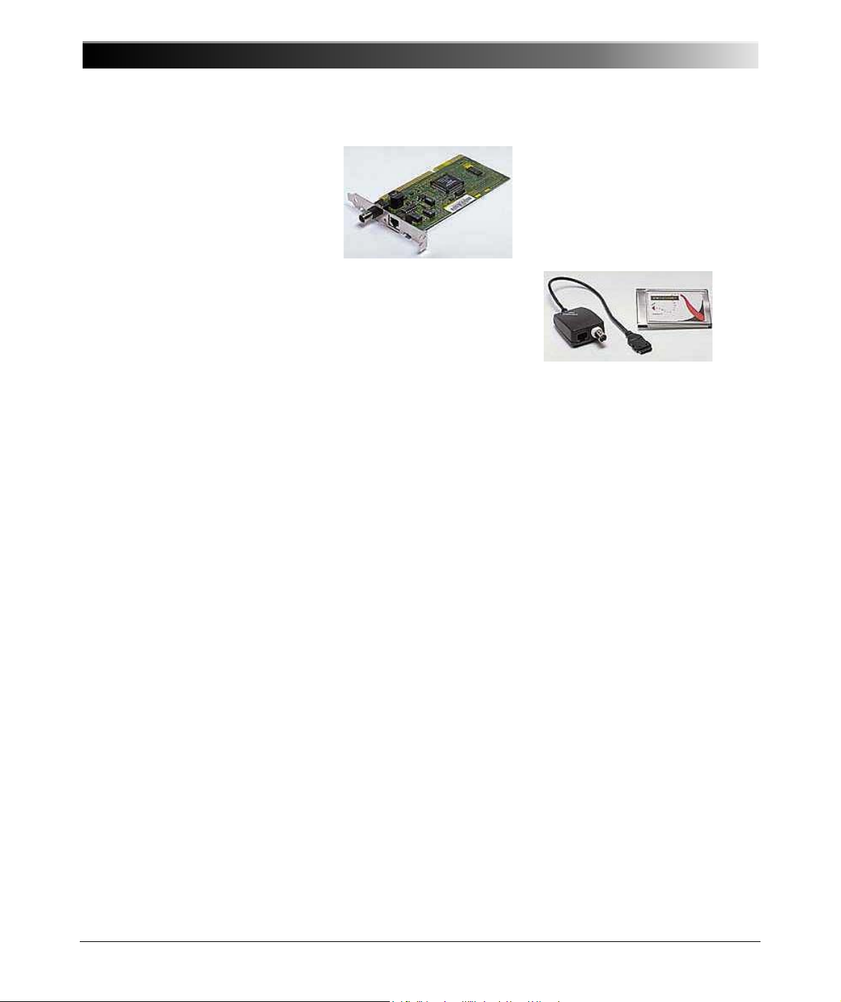
Typical Ethernet network
interface card with BNC and
RJ-45 connectors
Typical PCMCIA Ethernet
network interface card for
notebooks with BNC and
RJ-45 connectors
Offline Not connected to the CPC 100, for example, "offline test
preparation" means: preparing a test with a PC using
CPC Editor.
PC Card
Press The term "press" in the context of working with the CPC 100
PCMCIA network interface card. See also
software (for example, press the Insert Card key) means:
NIC...
a) pressing a menu or an accelerator key
b) or setting the focus (
element by navigating to it with the handwheel, and
pressing the handwheel to execute the Enter function
Quantity The term "quantity" designates a physical unit, such as Volt (V)
or Ampere (A).
rd rd = reading; used for determining the error value of a
measurement range (For an example, see ”General” on page
14-2.)
sel sel = frequency-selective measurement (see page 3-6)
Test object The object to be tested by the CPC 100, for example, a current
or voltage transformer.
Trigger A trigger is an "initiator". In this case it is an electrical signal, for
example, at CPC 100 binary input, whose occurrence causes
direct follow-up actions, such as switching off the output signals.
User
interface (UI)
V0 CPC 100 version V0 (see ”CPC 100 Versions” on page 15 of
V1 CPC 100 version V1 (see ”CPC 100 Versions” on page 15 of
Operational surface of a software. A user interface contains all
control elements necessary to work with the software.
this chapter)
this chapter)
Glossary) onto a UI ( Glossary)
1 - 4
Page 19

Preface
Safety Instructions for the CPC 100 and its
Accessories
Caution: Before operating the CPC 100, read the following safety instructions
carefully. Do not turn on and do not use the CPC 100 without understanding
the information in this manual. If some points of the safety instructions are
unclear, please contact OMICRON electronics.
Principle Use According to Regulations
•The CPC 100 should only be used in a safe manner, mindful of the dangers
while paying attention to the Reference Manual, and when it is in a technically
sound condition and when its use is in accordance with the regulations. In
particular, avoid disruptions that could in turn affect safety.
• If you have a cardiac pacemaker, do not use the CPC 100! Before operating
the CPC 100, make sure there is no person with a cardiac pacemaker in the
immediate vicinity.
•The CPC 100 is exclusively intended for the application fields specified in
detail in ”Designated Use” on page 1-13.
Any other use is deemed not to be according to the regulations. The
manufacturer/distributor is not liable for damage resulting from improper
usage. The user alone assumes all responsibility and risk.
• Following the instructions provided in this Reference Manual is also
considered part of being in accordance with the regulations.
• Do not open the CPC 100 housing.
Orderly Measures
• The Reference Manual, or alternatively the e-book in PDF format, should
always be available on the site where the CPC 100 is being used.
• Personnel assigned to use the CPC 100 should carefully read the Reference
Manual - in particular this section on safety instructions - before beginning to
work with it. On principle, this also applies to personnel who only occasionally
work with the CPC 100.
• Do not undertake any modifications, extensions, or adaptations to the
CPC 100.
•Use the CPC 100 in conjunction with original accessories only.
1 - 5
Page 20

CPC 100 V 1.44
Operator Qualifications and Primary Responsibilities
• Testing with the CPC 100 should only be carried out by authorized and
qualified personnel. Clearly establish the responsibilities!
• Personnel receiving training, instruction, direction, or education on the
CPC 100 should remain under the constant supervision of an experienced
operator while working with the equipment.
Safe Operation
When setting the CPC 100 into operation, follow the instructions in ”Putting the
CPC 100 into Operation” on page 2-49.
If you have a cardiac pacemaker, do not use the CPC 100! Before operating the
CPC 100, make sure there is no person with a cardiac pacemaker in the
immediate vicinity.
Note: Never use the CPC 100 without a solid connection to ground with at least
6 mm². Use a ground point as close as possible to the test object.
Power Supply
• Supply the CPC 100 only from a power outlet that has protective earth (PE).
• An error message (313) appears if either the PE connection is defective or
the power supply has no galvanic connection to ground. In this case, make
sure that the PE connection is intact. If the PE connection is intact and the
error message still appears, select the "Disable ground check" check box at
the Device Setup tab in the Options view (see ”Device Setup” on page 2-
35).
• Ground the isolating transformer outputs on the N (neutral) output or select
the "Disable ground check" check box as described above.
• Instead of supplying the CPC 100 from phase - neutral (L1-N, A-N), it may
also be supplied from phase - phase (for example, L1-L2; A-B). However, the
voltage must not exceed 240V AC.
• Fuse-protect the power supply (16 A automatic circuit-breaker).
• Do not use an extension cable on a cable reel to prevent an overheating of
the cord; run out the extension cord.
• Keep extension cables as short as possible to prevent power loss.
• If the power supply is
power at the 800A AC output.
190V AC, the CPC 100 cannot provide the full output
1 - 6
Page 21
Preface
The same applies when an external current booster is used. Therefore, in
order to gain the full output power, provide a sufficient power supply
(190V ... 240V AC).
Caution: The connector "Ext. Booster" is always galvanically connected to
mains, regardless whether or not an external booster is selected on the
software tab Options | Device Setup, the green warning light (0) is on, the
outputs are turned off or the Emergency Stop button is pressed.
Handle with extreme caution. Do not use any other booster cables than the
ones supplied by OMICRON electronics.
General
Warning: Before connecting or disconnecting test objects and / or cables, turn
off the CPC 100 by either the POWER ON/OFF switch or the Emergency Stop
button. Never connect or disconnect a test object while the outputs are active.
Note: Even if you switched off the CPC 100, wait until the red I / O warning light
is fully extinguished.
As long as this warning light is lit, there is still voltage and / or current potential
on one or more of the outputs.
• Make sure that a test object’s terminals that are to be connected to the
CPC 100 do not carry any voltage potential. During a test, the only power
source for a test object may be the CPC 100.
Caution: At their output sockets and especially in the cables connected to
them, in operation the high-current 400A DC and 800A AC outputs generate a
significant amount of heat (approx. 300 W/m at 800 A). To prevent burns, use
gloves when touching the cables while in operation or a short while after.
Warning: Do not insert objects (for example, screwdrivers, etc.) into any input/
output socket.
• Never use the test cards Quick and Resistance to measure the resistance
of windings with a high inductance because turning off the DC source results
in life-threatening voltage levels.
• For this kind of measurement only use the special winding resistance test
card RWinding!
• When measuring the ratio of voltage and power transformers make sure that
the test voltage is connected to the corresponding primary winding, and the
voltage of the secondary winding is the one that is measured. Accidentally
1 - 7
Page 22
CPC 100 V 1.44
mixing up the windings can generate life-threatening voltages within the
transformer.
For example: feeding a voltage of 100V /
voltage transformer that has a ratio of 400000V /
voltage of 400000V /
• Make sure that when testing a current transformer by feeding a test current
into its primary winding, all secondary windings are shorted. On open
secondary windings, life-threatening voltages can be induced!
3 in the transformer’s primary winding.
3 to the secondary winding of a
3 : 100V/3, induces a
DC output to test objects with a high inductance
Use the RWinding (winding resistance) and TRTapCheck (tap changer winding
resistance and on-load tap changer interruption check) test cards only.
Warning: As long as the CPC 100 software shows the on-screen message
"Switch off in progress", NEVER connect or disconnect test objects and / or
cables.
The message "Switch off in progress" notifies you
that, after the CPC 100 was switched off, the
connected external inductance (that is, the test
object) still "feeds" voltage potential back into the
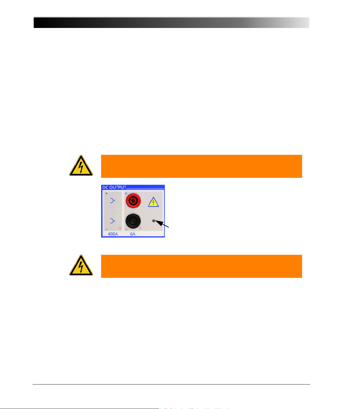
6A DC or 400A DC output.
1 - 8
The existence of this voltage potential at the 6A DC
output is also indicated by a lit LED - even if the
CPC 100 is switched off.
Warning: The CP SA1 (see ”CP SA1” on page 15-17) must be connected to
the CPC 100 VDC input sockets when using the 400A DC output to protect
yourself and the CPC 100 from high-voltage hazards.
If a test object with a big inductance was connected to the CPC 100, short-out
the test object additionally before disconnecting it from the CPC 100.
Page 23
Preface
High-voltage and high-current outputs
• Use only one CPC 100 output at a time.
• All AC and DC output sockets of the CPC 100 can carry life-hazardous
voltage potential and provide life-hazardous currents. Therefore:
– While connecting cables to the CPC 100 high-voltage or high-current
outputs or other conducting parts that are not protected against accidental
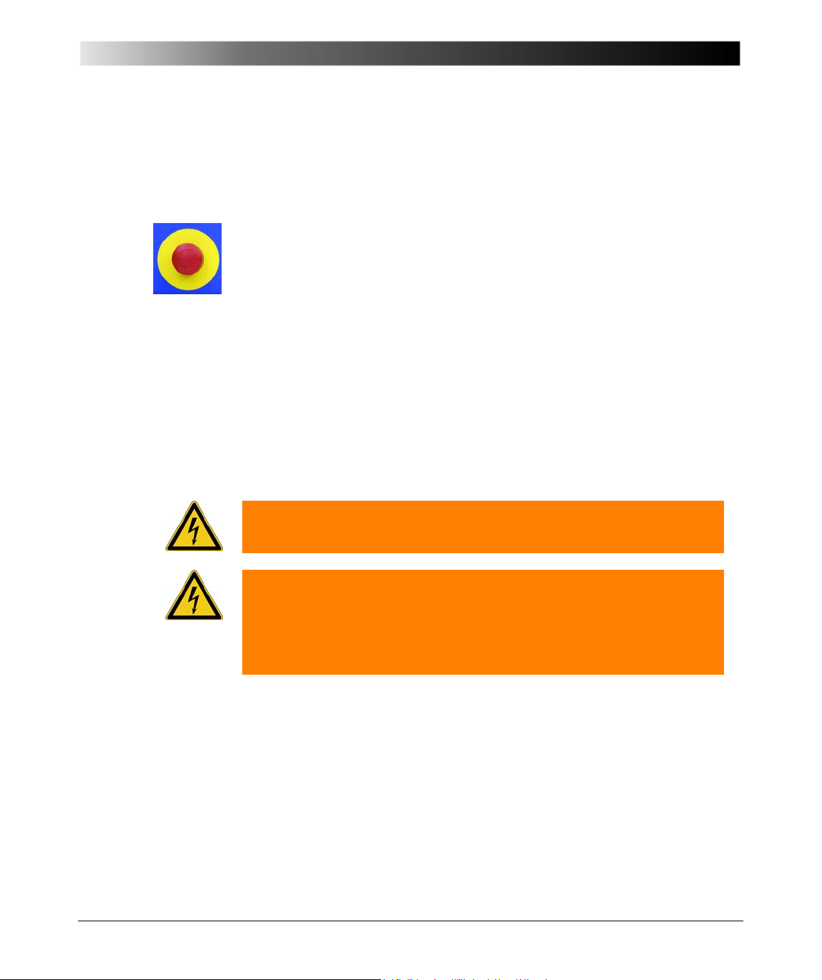
contact, press the Emergency Stop button, and keep it pressed as long
as an output signal is not absolutely necessary for the test.
– When connecting to the front panel input/output sockets, use wires with
either 4 mm safety "banana" connectors and plastic housing or, where
applicable, with the especially manufactured counterpart supplied by
OMICRON electronics (for example, for the V2 AC measuring input).
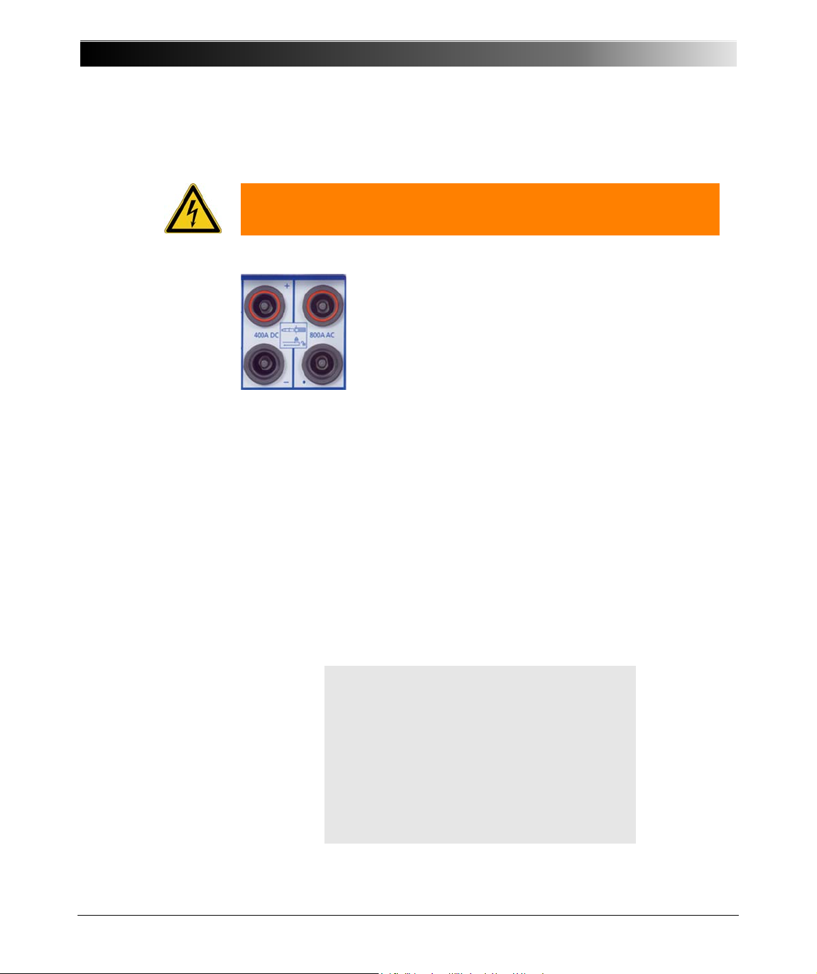
– For the high-voltage and high-current output connectors on the left-hand
side of the test set (2kV AC, 400A DC and 800 A AC, ext. Booster), only
use the specially manufactured cables supplied by OMICRON electronics
(refer to ”Cables” on page 15-18).
One end of the high-voltage cable has a coaxial safety plug that is
certified for a voltage level of 2kV AC. The other end is equipped with a
safety banana plug that is insulated with a shrink tube.
Warning: When the CPC 100 is switched on consider this part of the cable a
hazard of electric shock!
Warning: If you do not use the high-current 400A DC or 800A AC outputs or
the high-voltage 2kV AC output, disconnect any cable that may be plugged in
to these sockets.
The 400A DC or 800A AC outputs are not switched off by internal relays.
Therefore, if a test mode is selected that does not use either one of these two
outputs, they still generate current.
– Do not stand right next to or directly underneath a connection point
because the clamps may fall off and touch you.
This is a physical and an electrical hazard.
– The red warning light on the CPC 100 front panel indicates hazardous
voltage and/or current levels at the CPC 100 outputs (red light "I" on or
flashing). The green warning light indicates that the CPC 100 outputs are
not activated.
Note: If none or both warning lights are on, the unit is defective and must not
be used anymore.
1 - 9
Page 24
CPC 100 V 1.44
The counterpart of the high-current sockets are locking
connectors.
To lock these connectors safely, insert them carefully until
you feel a "click" position. Now they are locked. Confirm this
by trying to pull them out. This should not be possible now.
To remove the locking connectors again, unlock them by
pushing them in first, and then pull them out.
FOR YOUR OWN SAFETY
Always follow the 5 safety rules:
1. Insulate
2. Secure to prevent reconnecting
3. Check isolation
4. Earth and short-circuit
5. Cover or shield neighboring live parts
– Both of the high-current output sockets on the left-hand side of the test set
(400A DC and 800A AC) usually carry a relatively low-voltage potential.
Warning: However, in case of an internal insulation fault these outputs may
carry up to 300 V. Consider these outputs life-hazardous!
– Always insert connectors completely.
– The high-current cables for both the 800A AC and 400A DC outputs are
equipped with connection clamps at one end. If these connection clamps
are attached to a test object’s terminal that is situated above your head,
make sure the clamp is securely attached. Due to the weight of the cables
the clamp may become loose and fall down.
• Do not operate the CPC 100 under ambient conditions that exceed the
temperature and humidity limits listed at ”Technical Data” on page 14-1.
• Do not operate the CPC 100 in the presence of explosives, gas or vapors.
• Opening the CPC 100 invalidates all warranty claims.
•If the CPC 100 or any add-on device or accessory does not seem to function
properly, do not use it anymore. Please call the OMICRON electronics
hotline.
1 - 10
Page 25

Preface
Changing Fuses
• Turn off the CPC 100, unplug the power cord and/or press the Emergency
Stop button.
• We recommend to wait for about 30 seconds. This time is necessary for the
internal electrolytic capacitors to fully discharge.
• Ground the test object, and disconnect it from the CPC 100. By
disconnecting it you prevent a possibly faulty test object feeding power back
into the CPC 100.
• Locate the blown fuse on the front panel of the CPC 100, and replace it:
– 6.3A T (6.3 Amps slow-acting wire fuse 5x 20 mm) for AC OUTPUT in 6A
operation mode
– 3.15A T (3.15 Amps slow-acting wire fuse 5x20 mm) for AC OUTPUT in
130V operation mode.
– 10A FF (10 Amps very-quick-acting wire fuse 5x 20 mm) for measuring
inputs.
1
or for DC OUTPUT.
Note: Replace with identical fuse type only.
1. For detailed information about the difference between the 6A and the 130V operation mode refer
to ”Functional Components of the CPC 100” on page 2-2.
1 - 11
Page 26

CPC 100 V 1.44
CPC 100 in Combination with the CP TD1
The CP TD1 is an optionally available high-precision test system for on-site
insulation tests of high-voltage systems like power and measuring transformers,
circuit breakers, capacitors and isolators. The CP TD1 works as an add-on
device to the CPC 100 and is described in the CP TD1 Reference Manual
contained on the CPC 100 Toolset DVD and the CPC 100 Start Page.
On principle, the safety instructions that apply to the CPC 100 and its
accessories also apply to the CP TD1. However, the CP TD1 requires some
additional precautions and measures. They are listed in the CP TD1 Reference
Manual.
Different Symbols for PE
The CPC 100 and CP TD1 use different symbols for protective earth (PE):
This is due to a new standard and does not symbolize any functional difference.
Note: Both symbols mean exactly the same, that is, protective earth (PE) or
equipotential ground.
1 - 12
Page 27

Preface
Designated Use
The CPC 100, in conjunction with its accessories or as a stand-alone unit, is a
multi-purpose primary test set for commissioning and maintaining substation
equipment. It performs current transformer (CT), voltage transformer (VT) and
power transformer (TR) tests. Furthermore, it is used for contact and winding
resistance testing, polarity checks as well as primary and secondary protection
relay testing.
The various, partly automated tests are defined and parameterized via the front
panel control of a built-in ePC (
Glossary).
Functionality of the CPC 100
• Current transformer (CT)
– testing ratio, polarity (and burden) with injection to current input
– testing ratio, polarity (and burden) with a current clamp
– testing secondary burden
– measuring the excitation curve
– measuring winding resistance
– dielectric withstand voltage test (2kV AC)
– polarity check
– testing ratio and polarity by measuring the voltage ratio
– testing ratio and polarity of a Rogowski coil
– testing ratio and polarity of low-power current transformer
• Voltage transformer (VT)
– testing ratio and polarity
– testing secondary burden
– dielectric withstand voltage test (2kV AC)
– polarity check
– testing ratio & polarity of non-conventional electronic voltage transformers
1 - 13
Page 28

CPC 100 V 1.44
• Power transformer testing (TR)
– ratio and polarity / tap changer test
– measuring winding resistance
– testing tap changer contacts
– dielectric withstand voltage test (2kV AC)
• Resistance testing
– measuring contact resistance (µ
– measuring winding resistance (µ - k)
– measuring earth resistance (µ
– dielectric withstand voltage test (2kV AC)
• Other applications
– Ramping, a pogrammable ramping generator and determination of
thresholds
– Sequencer for automatic testing with different states in real time
– Comment card to hold a user-defined comment and/ or note regarding
the actual test procedure.
– When using the Amplifier test card, an input signal fed into a
synchronization input drives the high-current output’s magnitude,
frequency and phase angle.
• Insulation tests (TanDelta)
CP TD1 for on-site insulation tests of high-voltage systems like power and
measuring transformers, circuit breakers, capacitors and isolators.
• Automated testing of each application via front panel control
• Automatic report generation: test results are automatically recorded and
saved together with the test card
•The CPC 100 can be connected to an external PC via an Ethernet
connection. This way, test reports, for example, can be loaded onto this PC
and customized in standard applications.
•The CPC 100 provides a "dead man" function, that is the possibility to install
an additional push-button that stops remote operation if released (refer to
”ePC Interfaces” on page 2-4).
)
- k)
1 - 14
Note: Any other use of the CPC 100 but the one mentioned above is considered
improper use, and will not only invalidate all customer warranty claims but also
exempt the manufacturer from its liability to recourse.
Page 29
Preface
CPC 100 Versions
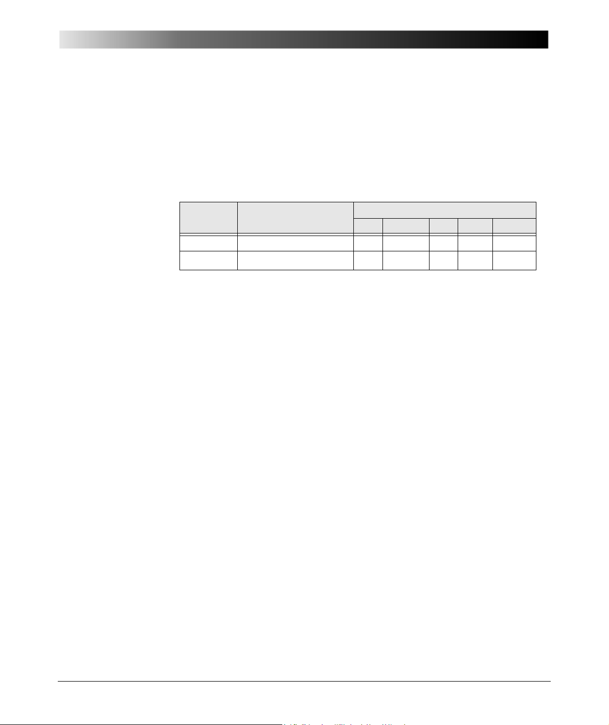
Two different CPC 100 versions exist, V0 and V1. An upgrade from the version
V0 to V1 is possible. For CPC 100 V1 units you will find the text "V1" in the
"Options" field of the nameplate on the right-hand side of your CPC 100.
Depending on the version, the CPC 100 is delivered with different processor and
ePC interface options described below.
CPC 100
Version
Processor
PC Network USB Serial Safety
ePC Interfaces
V0 66 MHz x86 compatible × × × ×
V1 400 MHz RISC CPU
1. CPC 100 V1 units are equipped with one socket for connecting the CPC 100 to both a PC and
a network hub.
1
×
1
×
×× ×
For detailed information on the ePC interfaces, see ”ePC Interfaces” on page 2-
4.
1 - 15
Page 30

CPC 100 V 1.44
1 - 16
Page 31

Introduction
Introduction
Contents of this section
Functional Components of the CPC 100......................................... page 2-2
Front Panel ................................................................................ page 2-2
High-Voltage and High-Current Outputs .................................... page 2-3
ePC Interfaces ........................................................................... page 2-4
Functional Components in Detail ............................................... page 2-6
CPC 100 Block Diagram (Simplified) ............................................ page 2-13
Built-in ePC ................................................................................... page 2-14
How to Use the CPC 100 Software ............................................... page 2-17
The Principles of Test Cards and Test Procedures ................. page 2-17
Starting the Software ............................................................... page 2-20
View Selector ........................................................................... page 2-21
Accelerator Keys...................................................................... page 2-22
Test Card View ........................................................................ page 2-22
Inserting Test Cards............................................................ page 2-23
Setting Up a Test Card ....................................................... page 2-25
Settings Page...................................................................... page 2-28
Starting a Test..................................................................... page 2-29
Temperature Monitoring...................................................... page 2-30
Test Procedure Overview ........................................................ page 2-31
The CPC 100 File System ....................................................... page 2-32
Options..................................................................................... page 2-35
Creating Defaults and Templates ............................................ page 2-44
Installation of the CPC 100 Toolset............................................... page 2-48
Computer Requirements.......................................................... page 2-48
Putting the CPC 100 into Operation.............................................. page 2-49
Principle Steps to Carry Out a Test with the CPC 100 ............ page 2-50
2 - 1
Page 32
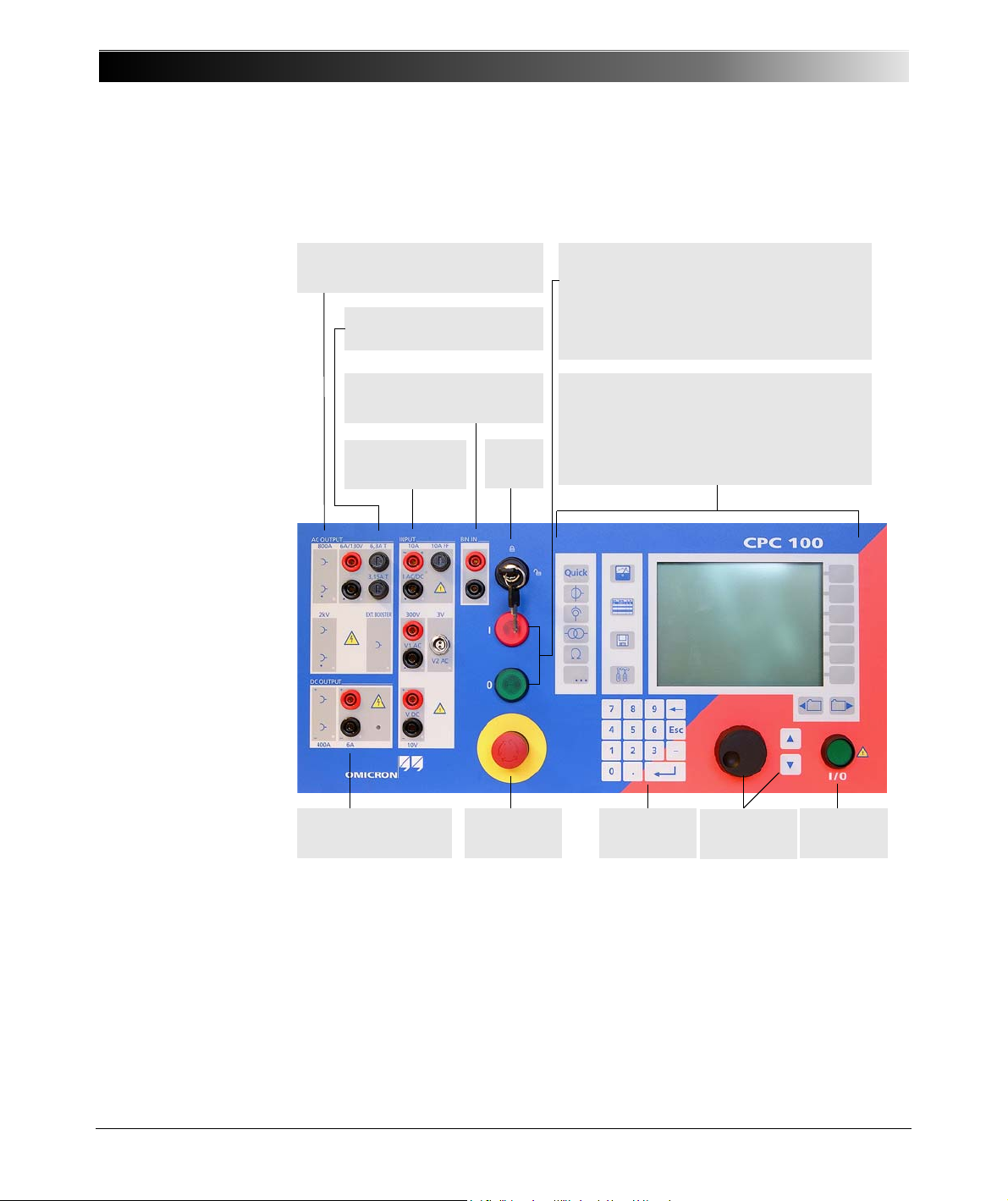
CPC 100 V 1.44
Soft-touch
keyboard
Built-in ePC
Built-in ePC with front-panel control
We recommend not to use more than 15 test cards
or 50 test results in one test procedure
(see Note below).
I / 0
Warning lights that indicate either a safe operation,
that is, no voltage at the CPC 100 outputs (green
light "0" on), or an operation with possibly
hazardous voltage and/or current levels at the
CPC 100 outputs (red light "I" flashing).
Safety
key lock
Emergency
stop button
Navigation
elements
DC OUTPUT
6A DC output
Test
Start/Stop
BIN IN
Binary trigger input
INPUT
Measuring inputs
AC OUTPUT
Fuse-protected 6A or 130V output
Fuses for 6A AC and 6A DC
outputs
Functional Components of the CPC 100
Figure 1:
CPC 100 front view
Front Panel
2 - 2
Note: With the CPC 100 V0, the number of test cards in one test procedure
should be limited to 15 to avoid memory problems. The CPC 100 V1 allows
using more test cards in one test procedure but we recommend not to use more
than 15 test cards or more than 50 test results to keep the tests clearly
structured.
Page 33
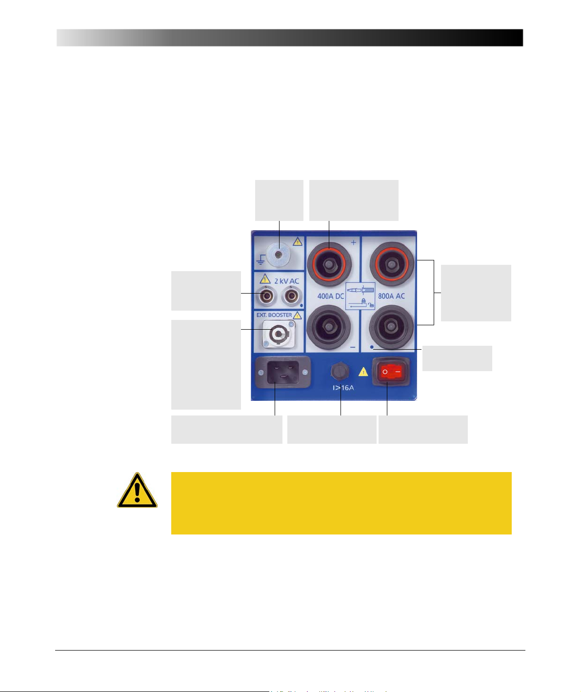
Figure 2:
800A AC
(6.1- 6.5 V AC)
High AC current
output
POWER ON /OFF
switch
Mains power supply,
1 phase, 85V-264V AC
2kVAC
High-voltage
output
400A DC
(4-4.5 V DC)
High DC current output
Ext. Booster
for example, for
the connection of
the CP CB2
current booster
option for output
currents of up to
2000A
Grounding
terminal
Automatic circuit
breaker I > 16A
Reference point
High-voltage and highcurrent outputs on lefthand side of the
CPC 100
Introduction
High-Voltage and High-Current Outputs
When the CPC 100 outputs high current, observe the allowed duty cycles that
may apply to the selected AC output range. For more information please refer to
”CPC 100 Outputs” on page 14-5.
Caution: The connector "Ext. Booster" is always galvanically connected to
mains, regardless whether or not an external booster is selected on the
software tab Options | Device Setup, the green warning light (0) is on, the
outputs are turned off or the Emergency Stop button is pressed.
Handle with extreme caution!
2 - 3
Page 34
CPC 100 V 1.44
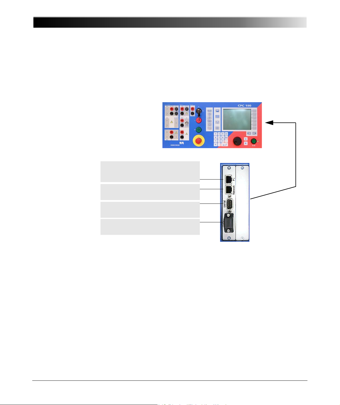
RJ-45 socket for connecting the CPC 100 to
either a PC’s Ethernet network card or a
notebook’s PC NIC ( Glossary)
RJ-45 socket for connecting the CPC 100 to a
PC network hub
Serial interface connector for connecting
optional CP TD1 test set
Connector for external safety functions (see item
3 below)
Figure 3:
ePC interfaces of the
CPC 100 V0
ePC Interfaces
The ePC interfaces are located on the right-hand side of the CPC 100 housing.
The PC and network interfaces differ depending on the CPC 100 version as
described below.
2 - 4
1. For more information on the PC and network interfaces, see ”CPC 100 in a
Network” on page 10-1.
2. For the pin assignment of the RS232 serial interface connector, see ”ePC
Interfaces” on page 14-29.
3. The connector for external safety functions allows connecting:
• an external Emergency Stop or "dead man" button
• an external "test start/ stop" push-button
• external I/O warning lights.
The attached plug contains a jumper for the emergency stop or "dead man"
function, and as long as the plug is placed on the connector, these functions
are bridged. If the plug is removed, emergency stop is active.
For the plug’s pin assignment and a wiring scheme, see ”Connector for
External Safety Functions” on page 14-31.
Page 35
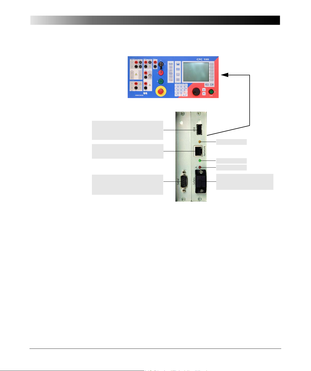
Figure 4:
USB connector for connecting
OMICRON USB memory sticks
(see below)
RJ-45 socket for connecting the
CPC 100 to a PC or a network hub
Serial interface connector for
connecting optional CP TD1 test set
(see item 2 above)
Connector for external safety
functions (see item 3 above)
Red LED
Yellow LED
Green LED
ePC interfaces of the
CPC 100 V1
Introduction
The CPC 100 V1 supports the USB interface 1.1 and 2.0 for connecting the USB
memory stick shipped with the CPC 100.
Note: The full functionality is guaranteed only for the stick delivered with the
CPC 100.
The serial and safety interfaces are identical with the CPC 100 V0 version (see
above). The network interface is an auto-crossover Ethernet connector that can
be connected to a network hub or directly to a PC or a notebook.
The CPC 100 V1 provides the following LEDs on the ePC interface:
• Green LED lights if the CPC 100 is properly connected to a PC or network.
• Yellow LED lights if data is transferred from or to the network.
• Red LED serves for diagnosis purposes.
2 - 5
Page 36
CPC 100 V 1.44
Lit LED indicates that
output is selected.
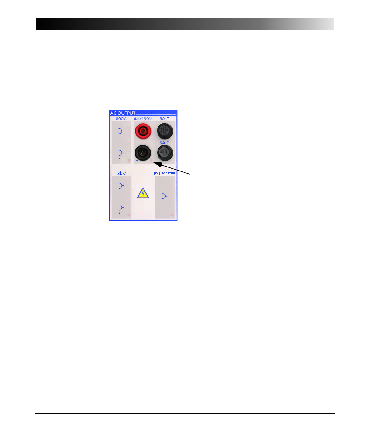
Figure 5:
Functional group
AC OUTPUT
Functional Components in Detail
AC OUTPUT
Programmable AC current and voltage outputs.
1. The front panel output 6A/130V operates as either a 0 … 6A AC or a
0 … 130 V AC output. The output range and the actual values are set by the
software.
In current mode 0 … 6 A, the maximum output voltage is 55 V (330 VA).
In voltage mode 0 … 130 V, the maximum output current is 3 A (390 VA).
The 6.3A T (6.3 Amps slow-acting wire fuse 5 x20 mm) protects both the
AC OUTPUT in 6A current mode and the DC OUTPUT.
The 3.15A T (3.15 Amps slow-acting wire fuse 5x 20 mm) protects the
AC OUTPUT in 130V voltage mode and in the 3A AC current mode.
2. The 800A output sockets are situated at the left-hand side of the CPC 100
as shown on page 2-3.
They provide an AC current of 0 … 800 A at a voltage of 6.1 … 6.5 V. The
actual output power (4880 VA max.) is range-dependent. For details refer to
”High-Current and High-Voltage Outputs” on page 14-5.
The current that flows from this output is measured internally by the
CPC 100, and displayed on the respective test card.
3. The 2kV output sockets are situated at the left-hand side of the CPC 100 as
shown on page 2-3.
2 - 6
Page 37

Introduction
They provide an output voltage of either
• 0 … 0.5 kV with a maximum current of 5 A, or
• 0 … 1 kV with a maximum current of 2.5 A, or
• 0 … 2 kV with a maximum current of 1.25 A.
For details refer to ”High-Current and High-Voltage Outputs” on page 14-5.
Both the voltage of this output and the current that flows from this output are
measured internally by the CPC 100, and displayed on the respective test
card.
All outputs are overload and short-circuit-proof and protected against external
high-voltage signals as well as over-temperature.
Note: The length of time a high current or a voltage can be applied may be
limited due to a high temperature occurrence of the internal transformer
windings and/or heat dissipaters. This high temperature occurrence may even
be increased if the CPC 100 is operated in a hot environment or is exposed to
direct sunlight.
It is highly recommended not to exceed the typical duration time t
specified
max
for each current and voltage output (refer to ”CPC 100 Outputs” on page 14-5).
If you do, and the CPC 100 develops too high an internal temperature, the
outputs are shut off automatically.
2 - 7
Page 38
CPC 100 V 1.44
LED indicates that output is
selected.
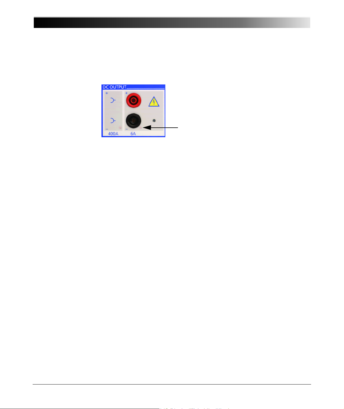
Figure 6:
Functional group
DC OUTPUT
DC OUTPUT
Programmable DC current output.
1. The 6A output provides a DC current of 0 … 6 A with a maximum output
voltage of 60V (360W). The output value is set by the software.
The 6.3A T (6.3 Amps slow-acting wire fuse 5 x20 mm, situated at the front
panel’s AC OUTPUT group) protects both the AC OUTPUT in 6A current
mode and the DC OUTPUT.
2. The 400A output is situated at the left-hand side of the CPC 100 as shown
at ”High-Voltage and High-Current Outputs” on page 2-3.
They provide an output current of 0 … 400 A at a voltage of 4 … 4.5 V. The
actual output power (2600 W max.) depends on the current magnitude. For
details refer to ”High-Current and High-Voltage Outputs” on page 14-5.
The current that flows from this output is measured internally by the
CPC 100, and displayed on the respective test card.
All outputs are overload and short-circuit-proof and protected against external
high-voltage signals as well as over-temperature.
Note: The length of time a high current or a voltage can be applied may be
limited due to a high temperature occurrence of the internal transformer
windings and/or heat dissipaters. This high temperature occurrence may even
be increased if the CPC 100 is operated in a hot environment or is exposed to
direct sunlight.
It is highly recommended not to exceed the max. duration time t
specified for
max
each current and voltage output (refer to ”CPC 100 Outputs” on page 14-5). If
you do, and the CPC 100 develops too high an internal temperature, the outputs
are shut off automatically.
2 - 8
Page 39
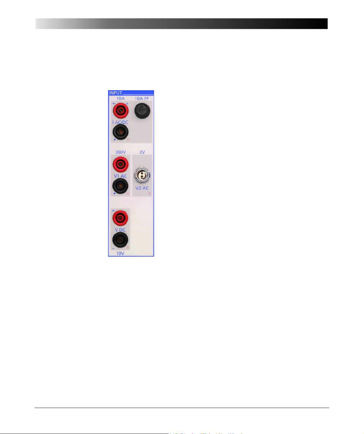
Figure 7:
1. IAC/DC current measuring input 10A AC and DC
Measuring input for AC and DC current of 0 … 10 A,
depending on the selected test card. AC current is
measured in a frequency range of 15 … 400 Hz.
For both AC and DC current measurement, the
software changes automatically between the two
measuring ranges 1 A and 10 A. In both ranges the
measuring error is < ± 0.2 %.
A 10A FF (10 Amps very quick-acting wire fuse
6.3x32 mm) protects the 0 … 10A AC/DC current
measuring input.
2. V1 AC voltage measuring input 300V AC
Measuring input for AC voltage of
0 … 300V AC voltage is measured in a frequency
range of 15 … 400 Hz.
During measurement, the software changes
automatically between the measuring ranges 0.3 V,
3 V, 30 V and 300 V.
For details about the accuracy of the individual ranges,
please refer to ”300V V1 AC Input” on page 14-23.
Functional group INPUT
Introduction
INPUT
Analog precision measuring inputs
3. V2AC low-level AC voltage measuring input
Measuring input for low-level AC voltage of 0 … 3 V in a frequency range of
15 … 400 Hz (for example, for low-power measuring transformers, or to
connect a current clamp).
The software changes automatically between the measuring ranges 0.03 V,
0.3 V and 3 V. For details about the accuracy of the individual ranges, please
refer to ”3V V2 AC Input” on page 14-25.
Note: The V1 AC and V2 AC inputs are galvanically connected. All other
inputs and outputs are separated.
4. VDC voltage measuring input 10V DC
Measuring input for DC voltage of 0 … 10 V. The software changes
automatically between the measuring ranges 0.01 V / 0.1 V / 1 V / 10 V.
2 - 9
Page 40
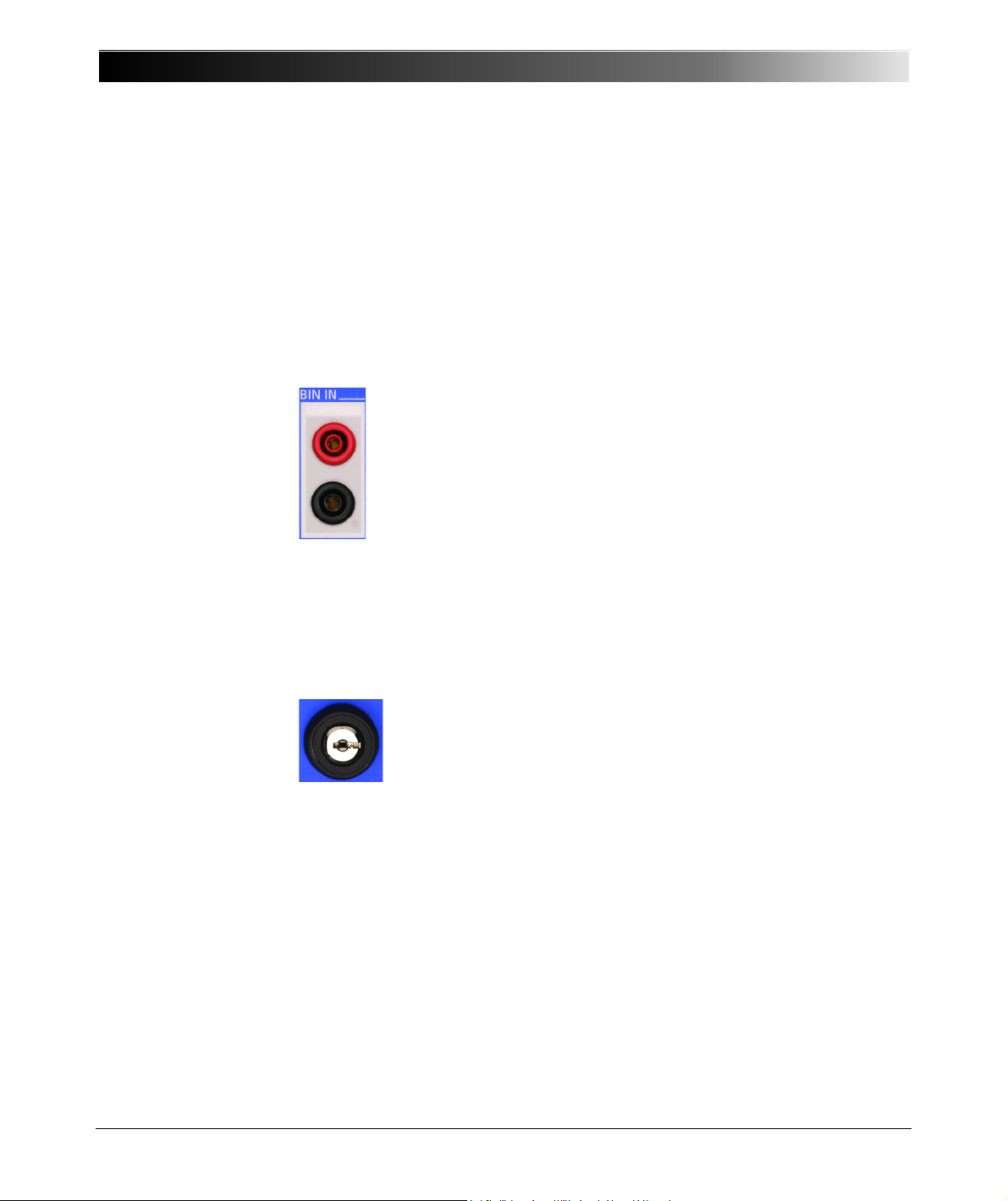
CPC 100 V 1.44
Binary trigger signal input to be used with a toggling potential-free
contact or with voltages up to 300V DC.
The response time of this input is 1 ms, and it is galvanically
separated from all other circuits.
1. Test not yet started, turn the key and remove it from key lock:
the software does not accept any more entries and/or
commands via the soft-touch keys and/ or the handwheel. The
test cannot be started by pushing the I/ O (test start / stop) pushbutton.
2. Test running, turn the key and remove it from key lock:
the current or voltage quantities presently applied are "frozen",
that is, can neither be changed by commands via the soft-touch
keys and/or the handwheel, nor turned off by pushing the
I /O (test start/ stop) push-button.
Note: Exception: the Emergency Stop button. An emergency
stop is possible at any time.
For details about the accuracy of the individual ranges, please refer to
”10V V DC Input” on page 14-27.
Figure 8:
Functional group BIN IN
Figure 9:
Safety key lock, shown
in position "enable"
Note: This measuring input is also used for resistance measuring (
in a range of 0.2
For more details about
…20k.
-measuring refer to ”Resistance” in chapter 7.
-meter)
BIN IN
Binary input for trigger signal
Safety Key Lock
To enable the CPC 100 entire functionality, put the key into the safety key lock
and turn it horizontally to the right (as shown in Figure 9).
In the "enable" position two effects are differentiated:
2 - 10
Page 41
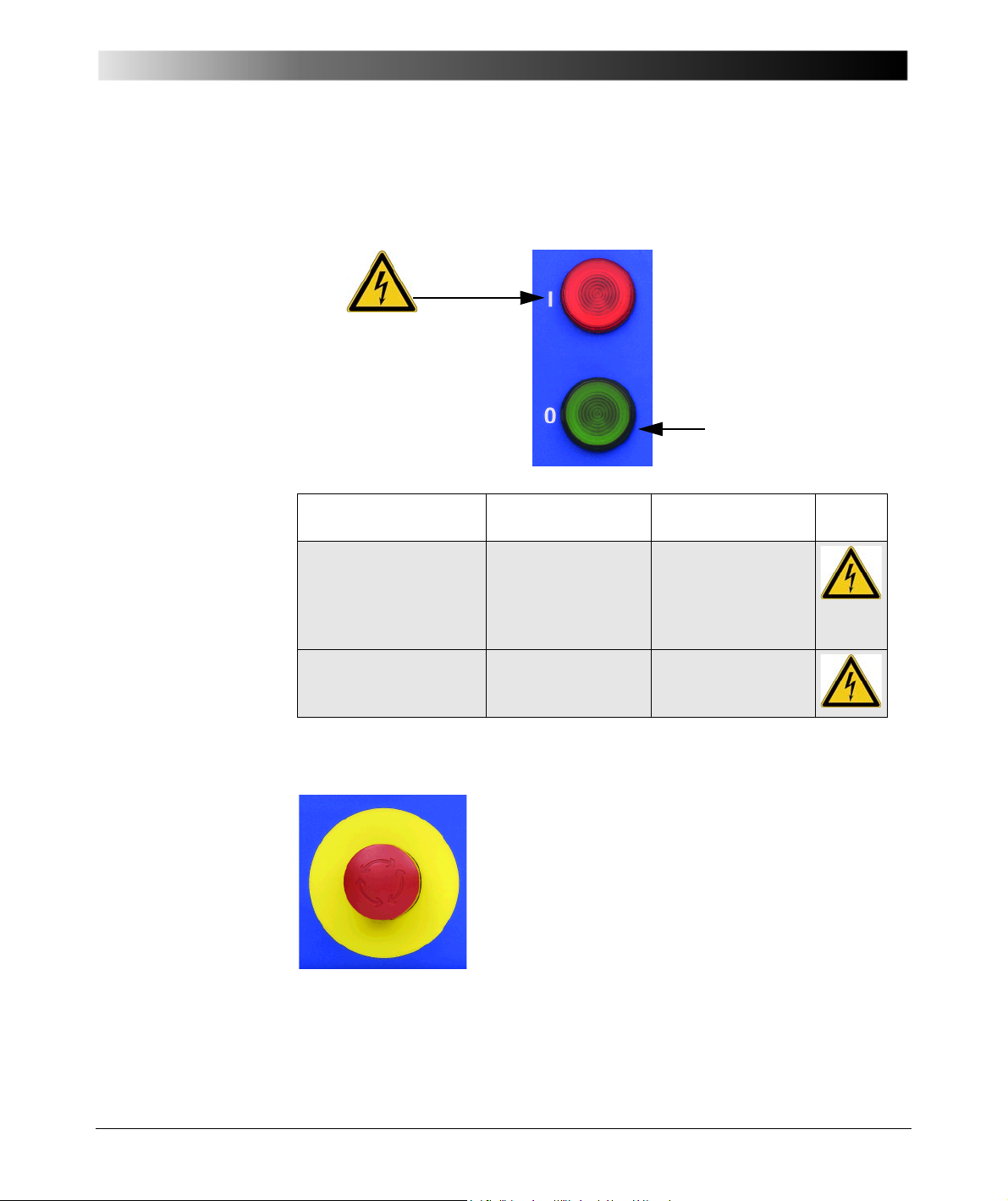
Figure 10:
Safe operating
condition
Dangerous
operating condition!
Pressing the Emergency Stop button immediately
shuts off all current and voltage outputs.
A running test is terminated, the software does not
accept any more entries and/or commands.
Once the reason for the Emergency Stop is cleared
and the Emergency Stop button released, the test
needs to be re-started by pressing the I / O
(test start/stop) push-button while in Test Card
View.
Warning lights
Introduction
Warning lights
The warning lights indicate either a safe or dangerous operating condition.
Figure 11:
Emergency Stop button
1. Outputs are
switched OFF
2. Output was selected
by the software,
Green warning light
(0) on
Red signal lamp (I)
flashes
values are set and
output is ready to be
switched ON
3. Output is switched ONRed signal lamp (I)
flashes
Emergency Stop Button
Safe operating
condition
Dangerous voltage
and/or current at
output.
Dangerous voltage
and/or current at
output.
2 - 11
Page 42

CPC 100 V 1.44
Ext. Booster
Socket to connect an external booster, for example, the CP CB2 current booster
for output currents of up to 2000 A.
Enable any external booster in the CPC 100 software on the tab
Options | Device Setup (refer to ”Device Setup” on page 35 of this chapter).
Warning: The connector "Ext. Booster" is always galvanically connected to
mains, regardless whether or not an external booster is selected on the
software tab Options | Device Setup, the green warning light (0) is on, the
outputs are turned off or the Emergency Stop button is pressed.
Handle with extreme caution!
2 - 12
Page 43
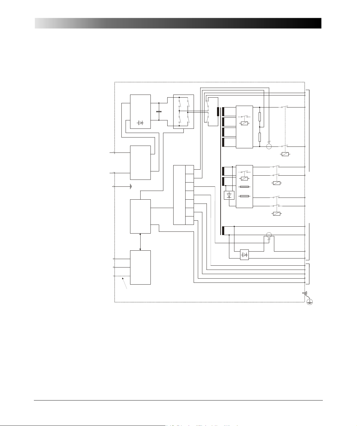
Figure 12:
+
Rectifier
& power
factor
corrector
Filter
Switched
mode
amplifier
500V 4A
1kV 2A
2kV 1A
500V
500V
500V
500V
65V
65V
3.15A
6.3A
ADC
I
U
U
U
U
I
I
DSP
(Digital
Signal
Processor)
Built-in
ePC
Ethernet
RS 232
optional
optional interfaces
(plug-in boards)
analog or digital
2kV
800A
R
R
-
+
5V / 400A DC
10A AC/DC
3V AC
300V AC
10V DC
BIN IN
65V / 6A DC
6V / 800A AC
2kV
Ext.
Booster
130V / 6A AC
Mains
100-240V
50/60Hz
to
ext.
PC
I
n
p.
O
utp
uts
L
N
PE
Simplified block
diagram of the CPC 100
Introduction
CPC 100 Block Diagram (Simplified)
2 - 13
Page 44
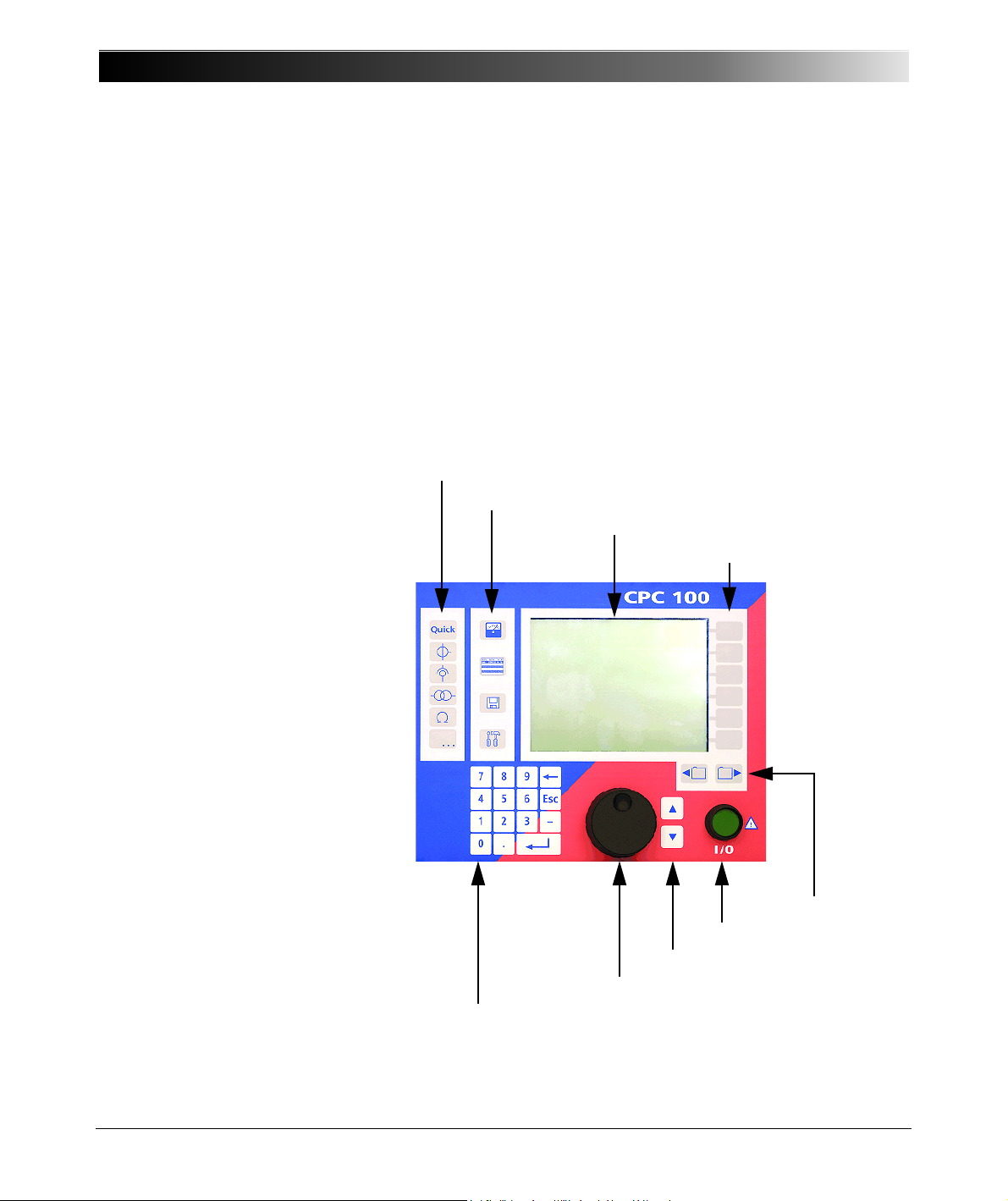
CPC 100 V 1.44
Accelerator keys
View selector
LCD monitor
Context-dependent menu keys
Tab selector
Test start/stop
Up/Down keys
Jog-dial handwheel
Soft-touch keyboard
Figure 13:
The CPC 100’s built-in
ePC, components
overview
Built-in ePC
The built-in ePC ( Glossary) of the CPC 100 runs under Microsoft
Windows CE operating system and provides front panel control.
This section provides a brief overview of the front panel control components.
Section ”How to Use the CPC 100 Software” on page 17 of this chapter
describes in detail how to work with the front panel control components, how to
set up a test, execute it and save it for later use.
Via the built-in ePC, the CPC 100 can be accessed from a stand-alone PC, for
example, a notebook, via a PC network and via the Internet (refer to ”CPC 100
in a Network” in chapter 10).
2 - 14
Page 45

Introduction
LCD monitor
The monitor is a high-contrast gray-scale graphical LCD display with a resolution
of 320x240 pixels.
Accelerator keys
Let you add the test card of your choice, for example, Quick, CT, VT... etc. (refer
to ”Accelerator Keys” on page 22 of this chapter).
View Selector
Lets you select the view of your choice, for example, Test Card View, Test
Procedure Overview, File Operations or Options (refer to ”View Selector” on
page 21 of this chapter).
Jog-dial handwheel
Advanced jog-dial handwheel with "click" (Enter) function.
In "navigation" mode, turning the handwheel navigates you through the UI
(
Glossary) elements within one test card. Pressing the Up/Down keys has
the same effect.
In "data entry" mode, that is, if the focus (
field or a combo box, and the handwheel was pressed to "enter" the field and to
enable data entry, turning the handwheel increases/decreases the entry field’s
value or browses through the preset values of the combo box, respectively.
Pressing the handwheel corresponds to the Enter function of the soft-touch
keyboard.
Furthermore, the wheel comprises an adaptive acceleration function, that is, if
the focus is, for example, set onto a data entry field, fast turning increments/
decrements a value in increasingly bigger steps, slow turning in decreasingly
smaller steps.
Up/Down keys
Soft-touch keys supplementing the handwheel. Depending on the current focus
in the software user interface, pressing these keys either navigates through the
UI elements within one test card, or - if in a data entry field, for example increments/decrements a value.
Contrary to the handwheel, the Up/Down keys change a value in fixed coarse
increments /decrements in order to ease a quick approximation to the end
value. The fine adjustment is then done with the handwheel.
Glossary) is set onto a data entry
2 - 15
Page 46
CPC 100 V 1.44
Context-dependent menu keys
Soft-touch keys that directly invoke specific commands associated with the
currently selected control of the test card and view.
Since their actual functions depend on the selected view, test mode, test card
and selected UI element, the menu keys do not hold any specific text. The
individual key function is displayed on the monitor with a labelled button symbol
right next to the menu key.
I/O (test start/stop)
If the test parameters are set in the software’s Test Card View, the Emergency
Stop button is released and the safety key lock is set to the "enable" position,
pressing this push-button enables the CPC 100 outputs and starts a test.
Pressing this push-button a second time stops the test.
Caution: Stopping a test does not shut off theCPC 100 outputs
instantaneously. First, the currently running test sequence finishes, then the
test execution is stopped.
Most test cards finish the running test sequence with a predefined ramp
function. Therefore, in a hazardous situation never press "Stop Test". Instead,
use Emergency Stop.
Tab selector
If a test procedure comprises more than one test card, use these keys to change
between the single test cards.
2 - 16
Page 47

Introduction
How to Use the CPC 100 Software
Note: This manual refers to the CPC 100 software version V 1.44. Information
about the software version of your CPC 100 can be found at the Options tab
System Info (refer to ”System Info” on page 43 of this chapter).
This section provides an overview of the front panel control components,
explains in detail how to navigate with them through the software, how to set up
a test, execute it, save it for later use, etc.
Note: The subsequent chapters (Quick, CT, VT, Resistance, Transformer...),
explaining the various test procedures from a more practice-orientated point of
view, are confined to test-relevant issues, and assume that you have read and
understood this section.
The Principles of Test Cards and Test Procedures
• Test cards
The CPC 100 software comprises a number of test cards. A test card carries
out one specific test, for example, measuring a CT excitation curve, or testing
the ratio of a voltage transformer.
A test card holds a number of user-definable test settings and - after the test
was run - test results.
• Test card default
Rather than repeatedly filling out blank test cards with frequently used
settings, any test card with its actual settings can be made a test card default
for that particular type of card, for example, filling out a CTRatioV test card
with certain values and pressing Save As Default makes this card the new
CTRatioV test card default.
Each card of this type that will later be inserted to a test procedure will
already hold these new settings.
Note: A test card default contains user-defined settings, not test results.
2 - 17
Page 48

CPC 100 V 1.44
• Test procedure
A test procedure contains multiple test cards.
The composition of such a test procedure and the settings of all single test
cards can be freely defined by the user. Within a test procedure, each test
card and its associated test is executed individually in a user-defined order.
Note: With the CPC 100 V0, the number of test cards in one test procedure
should be limited to 15 to avoid memory problems. The CPC 100 V1 allows
using more test cards in one test procedure but we recommend not to use
more than 15 test cards to keep the tests clearly structured.
• Test procedure default
A test procedure with all of its test cards and specific settings - but without
test results - can be made the test procedure default.
Note: When the CPC 100 software starts, it automatically loads the test
procedure default.
Initially, that is, as long as no user-defined test procedure default is created,
the the CPC 100 software loads one empty Quick test card.
• Report
For archiving or reporting purposes, or later processing, a test procedure with
all of its test cards, specific settings and - after the test was run - test results
and assessments can be saved. It is then considered a report.
Such a report can later be opened any time in CPC 100 File Operations
menu.
• Test procedure template
A report can be copied/ pasted to be a test procedure template.
In this process, the settings are preserved, however, the test results are
deleted.
2 - 18
Page 49
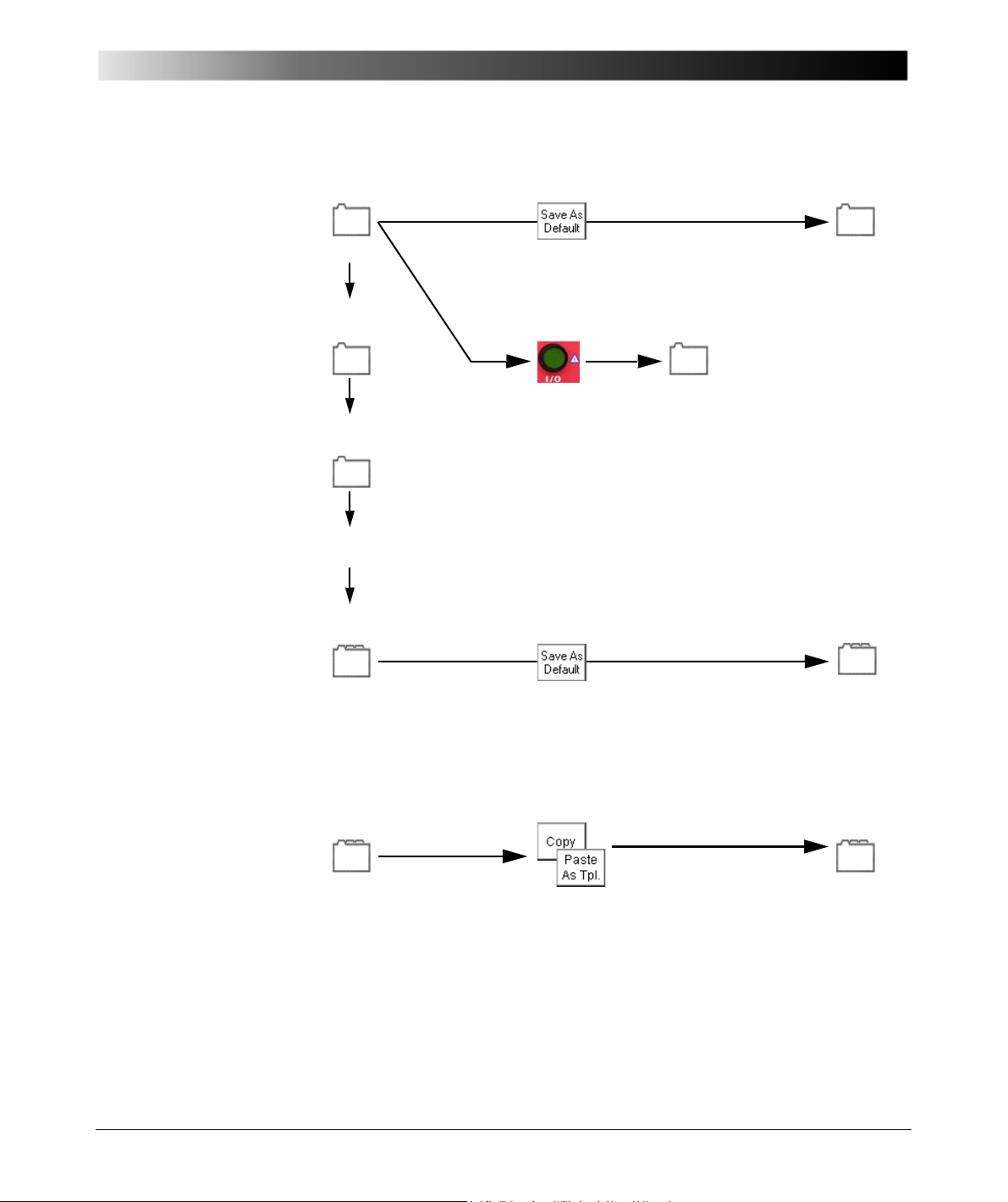
Figure 14:
Test Card
+
Test Card
+ Test
settings
settings
= Test
Procedure
settings
settings
+
results
+
Test Card
+
...
Test Procedure
Template
name.xmt
Test Card Default
(1)
Test Card
settings
settings
in Test Card View:
in Test Procedure Overview:
Test Procedure
Default
settings
Test Procedure
name.xml
(in file system)
in Test Procedure Overview:
The principles of test
cards, defaults and test
procedures
Introduction
(1) One Test Card Default for each type of test card
The following sections emphasize on test cards, defaults and templates in more
detail. Also refer to ”Creating Defaults and Templates” on page 44 of this
chapter.
2 - 19
Page 50

CPC 100 V 1.44
Starting the Software
When the CPC 100 is switched on, the operating system boots up, and the
CPC 100 software starts automatically.
During the hardware and software initialization phase, the software displays a
splash screen.
The CPC 100 software starts in the Test Card View loading the test procedure
default (refer to ”The Principles of Test Cards and Test Procedures” on page 17
of this chapter).
Initially, the test procedure default contains one empty Quick test card
However, this default can be customized according to your specific
requirements with as many test cards as needed and of all types of your choice.
By creating a user-defined test procedure default, the CPC 100 starts up loading
your most frequently used test cards already containing specific values.
To learn more about defining such a default, refer to ”Creating Defaults and
Templates” on page 44 of this chapter.
1
.
2 - 20
1. More about Quick at ”Getting Started with Quick” in chapter 3.
Page 51
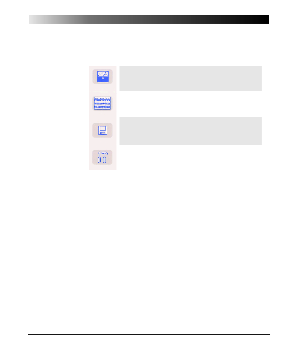
Figure 15:
Test Card View (default view upon start-up)
View to set up test cards, compose test procedures, enter test
settings, define test cards or the test procedure default, start
tests etc.
Test Procedure Overview
Provides an enhanced overview of all test cards of the currently
active test procedure. Defines the test procedure default.
File Operations
Lets you save, load, delete, copy and rename test procedures.
Some of these features call up the Phrase Editor (described at
”The String Editor” in chapter 9).
Options
Specify general parameters, such as display and regional
settings, date and time, decimal symbol, network settings,
system information and the device setup.
Note: If you are using a current clamp or an external current or
voltage booster, specify these devices at the Options tab
Device Setup before you start using them.
View selector
Introduction
View Selector
2 - 21
Page 52
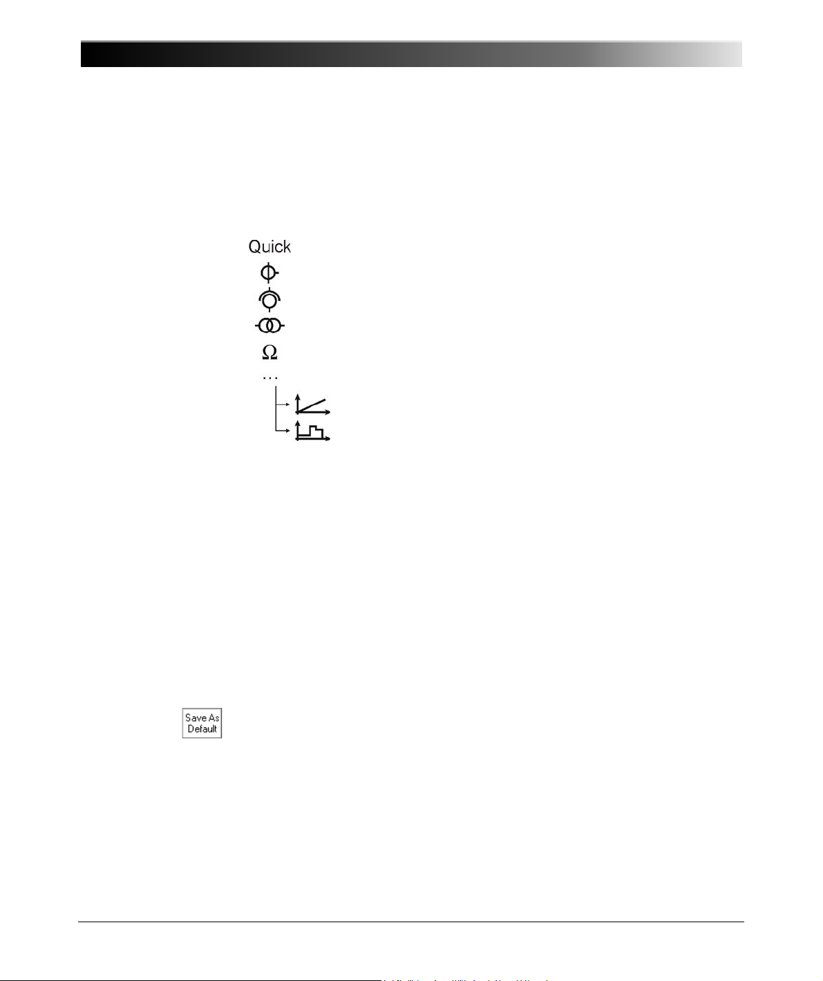
CPC 100 V 1.44
Accelerator Keys
With the exception of Quick, pressing an accelerator key opens the according
Insert a new test card dialog box and lets you select the test card of your
choice. Pressing Quick opens the Quick test card directly.
Quick test card
select from current transformer (CT) test cards
select from voltage transformer (VT) test cards
select from power transformer test cards
select from resistance test cards
select from other test applications...
– Ramping (primary / secondary protection relay testing)
– Sequencer (primary / secondary protection relay
testing)
– Amplifier card (refer to page 8-29).
– Comment card (refer to page 8-33).
TanDelta (refer to the CP TD1 Reference Manual available on
the CPC 100 Toolset DVD or the CPC 100 Start Page).
Test Card View
The Test Card View displays the test procedures. The CPC 100 software starts
in the Test Card View loading the test procedure default.
A test card inserted to the Test Card View loads the values from the respective
test card default. If no test card default has been defined yet by the user, the test
card opens with preset default values.
Any test card with its actual settings can be made a test card default for that
particular type of card, for example, filling out a CTRatioV test card with certain
values and pressing Save As Default makes this card the new CTRatioV test
card default.
Each card of this type that will later be inserted to a test procedure will already
hold these new settings.
Note: A test card default contains user-defined settings, not test results.
2 - 22
Page 53
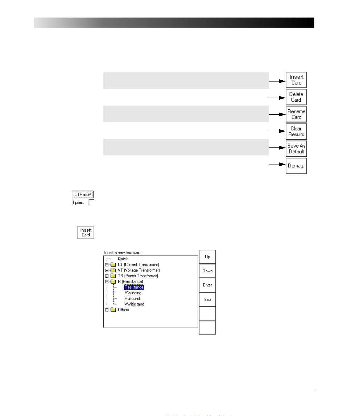
Introduction
Inserts a test card of your choice and places it after the
selected test card of the current test procedure.
Deletes the current test card from the test procedure.
Opens the String Editor. You can rename the current test card
to any new name of your choice (max. 15 characters).
Clears the results of the current test card, and thus enables the
start of a new test.
Makes the current test card with all of its settings the new
default for that particular type of card.
Context-dependent menu item
(shown here: "Demag.", CTExcitation).
The Test Card View comprises a number of context-dependent menu keys.
Some examples are given below:
Note: The actual function of the context-dependent menu keys depends on the
selected view, test mode, test card and selected UI element.
To make the above listed functions visible, the focus (
onto the test card tab designation, for example, CTRatioV.
Glossary) must be set
Inserting Test Cards
The Insert a new test card dialog box displays the available tests and their
associated test cards in a tree-like structure.
Figure 16:
Insert a test card
Use the context-dependent Up/ Down menu keys to the right, or the handwheel,
to browse through the structure.
2 - 23
Page 54

CPC 100 V 1.44
Due to usability reasons, some test cards, such as Winding Resistance,
Voltage Withstand Test or Polarity Check, appear in more than one test
mode, e.g., Winding Resistance appears in Current Transformer, Power
Transformer and Resistance.
With regard to their functionality, these test cards are identical.
To expand a collapsed group of tests , for example, CT, set the focus onto
this group, and press Enter or the handwheel.
The group of tests expands and displays all of its associated test
cards.
Browse to the test card of your choice, and when its highlighted press
Enter.
This will switch from the Insert a new test card dialog to the Test Card View,
inserting the test card of your choice after the last selected test card in the Test
Card View.
Note: Only test cards that are licensed can be inserted.
When you purchased the CPC 100, you purchased a license for a number of test
cards of your choice. Not licensed test cards are displayed in the Insert a new
test card dialog, but the attempt to insert one of them to the test procedure
results in an according on-screen message.
If you wish further information about licensing, please contact OMICRON
electronics.
2 - 24
You can insert as many test cards as needed and of all types of your choice by
repeating this process.
Note: With the CPC 100 V0, the number of test cards in one test procedure
should be limited to 15 to avoid memory problems. The CPC 100 V1 allows
using more test cards in one test procedure but we recommend not to use more
than 15 test cards to keep the tests clearly structured.
If you need more test cards in one test procedure, we recommend not to save
all cards in one, for example, the test procedure default, but to combine a smaller
number of cards to logical groups, and to save these logical groups as test
procedure templates with individual names (refer to ”Test Procedure Templates”
on page 47 of this chapter).
Pressing Esc closes Insert a new test card, and brings you back to the
previous view without inserting a new test card.
Page 55
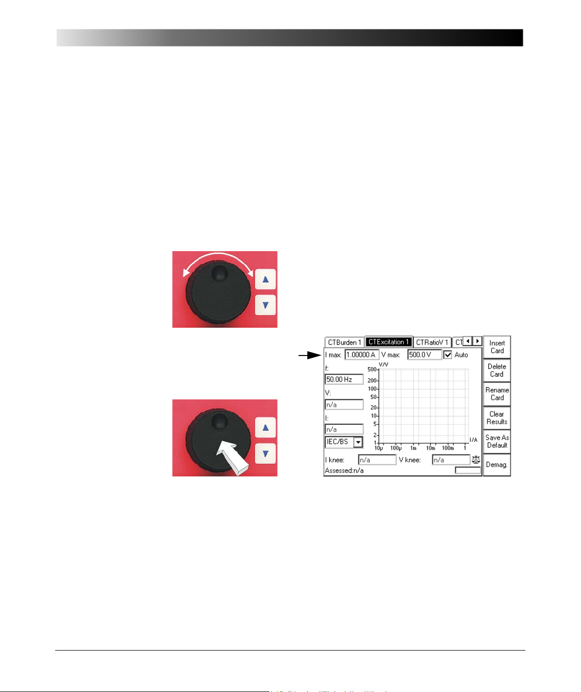
Introduction
Within one test card, to navigate to the UI element
of your choice either turn the handwheel or use the
Up/Down keys at the right-hand side of the
handwheel.
A selected UI element is entirely highlighted; it has
the focus (
Glossary).
If a data entry field, for
example, "Imax:" has the
focus, press the handwheel to
"enter" and enable the field.
Setting Up a Test Card
Note: Each parameter whose numerical value can be changed in a data entry
field has an associated minimum and maximum value as well as a preset
number of decimal characters. The parameter value can be changed freely
within this min. … max. range.
Furthermore, each numerical value has a
• fixed precision value that is used as a step size when increased/decreased
by means of the handwheel
• a coarse step value that is used as a step size when increased/decreased
by pressing the Up/Down keys.
As shown above, the value itself is highlighted, the unit is not, and at the value’s
end a blinking caret (cursor) indicates "ready for data entry".
Now either
• use the Up/Down keys to approximate the value of your choice quickly in
coarse predefined steps
• rotate the handwheel to fine-adjust the value in precision steps
• type in the value of your choice using the numeric soft-touch keys to the left
of the handwheel (refer to Figure 17).
2 - 25
Page 56
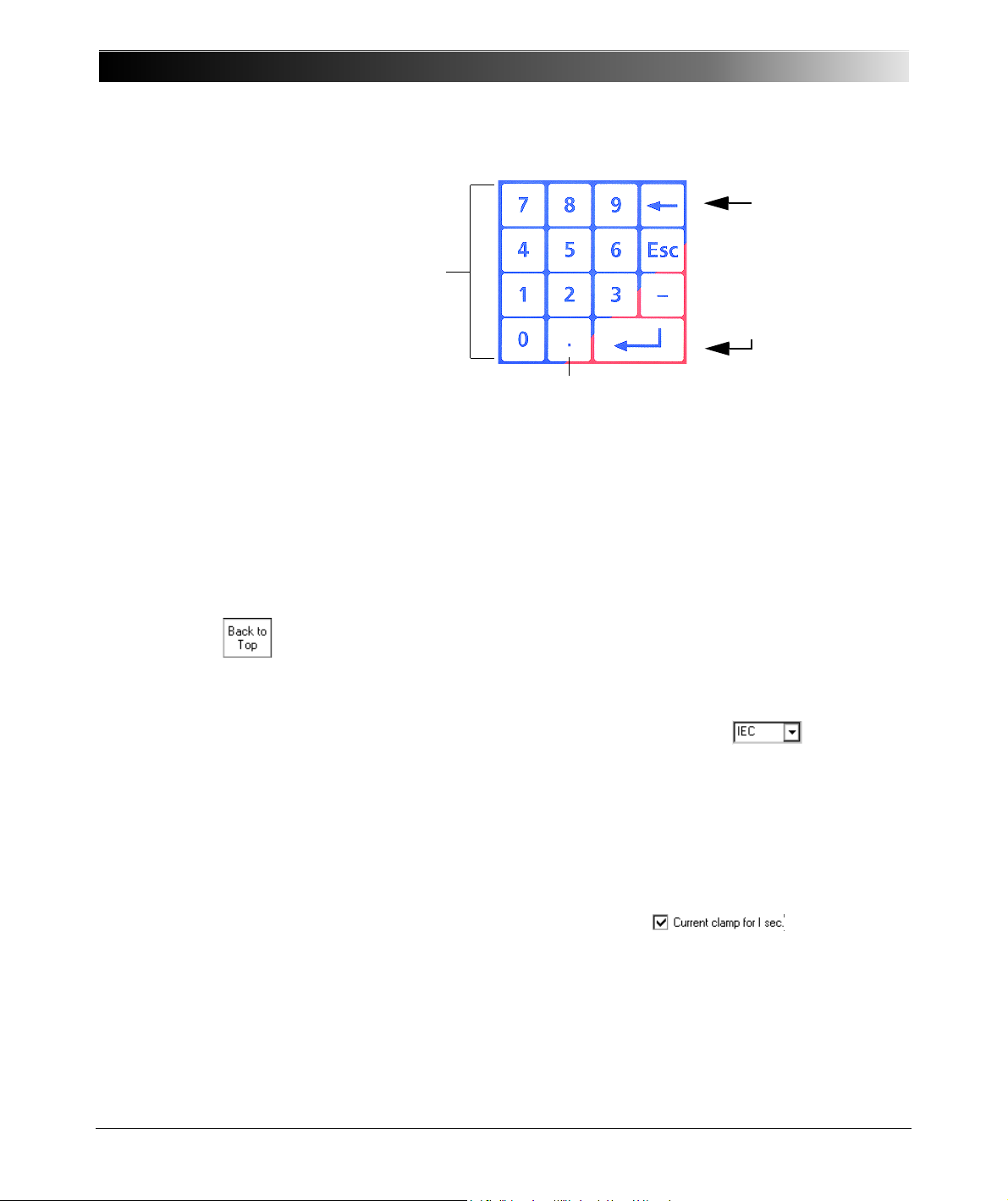
CPC 100 V 1.44
Soft-touch keys to
enter numerical
values.
Decimal point
: backspace
Esc: cancels the current
action without saving
— : prefix for negative
values, for example,
angles
: Enter
Figure 17:
Soft-touch keys to enter
numerical values
Pressing Esc on the soft-touch keyboard while entering a value, discards the
entry and restores the previous value.
When ready, press either the handwheel again or the Enter key to confirm your
entry, and move forward to the next UI element of your choice by turning the
handwheel or the Up/ Down keys.
Note: If a number key is pressed with the focus set onto a data entry field, this
number is automatically written to the data entry field, and the field is enabled
for data entry.
Pressing the context-dependent menu key Back to Top terminates the data
entry mode, accepts all current values and sets the focus onto the test card tab
designation.
Combo Box
The same principle applies at a combo box, for example, :
• press the handwheel (to "enter" the combo box for selection)
• and either navigate through the list of available parameters by rotating the
handwheel, or by using the Up/Down keys.
Pressing Esc while scrolling through the list of values closes the combo box and
returns to the previous value.
Check Box
Set the focus onto the check box, for example,
and press
either the Enter key or the handwheel to select /clear a check box.
2 - 26
Page 57
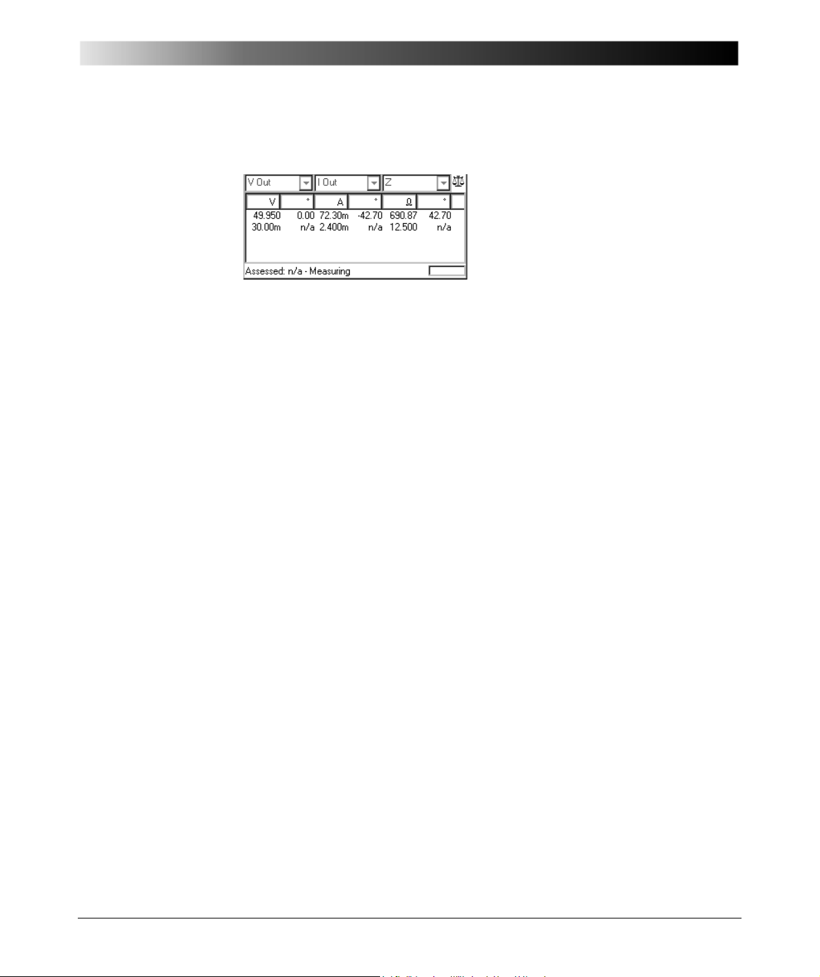
Figure 18:
Example of a list box
Introduction
List Box
List boxes are differentiated between read-only and editable list boxes:
• In a read-only list box (Figure 18), turning the handwheel scrolls from line to
line.
When using the Up/ Down keys, a read-only list box is treated as one UI
element, that is, pressing one of the keys exits the list box, and sets the focus
onto the next /previous UI element.
• In an editable list box, turning the handwheel scrolls from table cell to table
cell. Press either the handwheel or Enter to "enter" a cell and to edit the
value.
When using the Up/ Down keys, the focus proceeds to the same table cell
one line above or below.
2 - 27
Page 58

CPC 100 V 1.44
Figure 19:
Main page with
Settings menu key
Figure 20:
Settings page
Settings Page
Some test cards include the Settings menu key. Pressing the Settings menu
key opens the Settings page.
The Settings page with the exception of the TRRatio test card looks as shown
below.
2 - 28
The Settings page allows setting the test cards individually. At the
Device Setup tab in the Options view (see ”Options” on page 35 of this
chapter), the same properties can be set for all test cards of a test procedure.
As a rule, do not use the Settings page described here but the Device Setup
tab in the Options view to set the test cards. Making different settings for the
test cards is rarely a good idea. Set the test cards individually using the Settings
page only in well-founded cases.
If a test card contains results, the settings cannot be changed. When a file
containing results is loaded, the Settings page can be used to view the settings
of the test procedure.
Page 59
Introduction
Starting a Test
Note: Tests can only be started and stopped with the I / O (test start / stop) push-
button while in the Test Card View.
Each test card represents a separate test, and is started individually.
Preconditions to start a test
1. The required test card is defined, the test parameters are set.
2. The software is in the Test Card View.
3. The Emergency Stop button is released.
4. The safety key lock is set to the "enable" position.
Pressing the I/O (test start/ stop) push-button starts the test. Pressing this
push-button a second time stops the test.
Note: Stopping a test does not shut off the CPC 100 outputs instantaneously.
First, the currently running test sequence finishes, then the test execution is
stopped.
Most test cards finish the running test sequence with a predefined ramp function.
Caution: Therefore, in an emergency situation never press "Stop Test".
Instead, use Emergency Stop.
While a test is running, several functions such as changing the test card,
changing the view etc., are disabled.
To repeat the test, the test results need to be cleared beforehand. Otherwise the
start is blocked.
2 - 29
Page 60
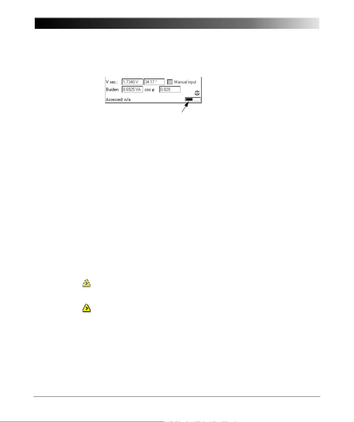
CPC 100 V 1.44
Temperature Monitoring
Each test card contains a progress bar-like temperature gauge that displays the
CPC 100 actual temperature condition. When the temperature limit is reached,
that is before an overheating condition occurs, the output is switched off
automatically.
In addition, if an output is activated, both the CPC 100 current consumption from
the power supply and the current emitted at the high-current outputs is
monitored and, together with the temperature, displayed by this temperature
gauge. The temperature gauge’s bar therewith represents an indicator for the
remaining time the CPC 100 can output power.
Just as with over-temperature, if these limit values are exceeded, the output is
switched off automatically.
With deactivated outputs, the temperature gauge’s bar represents an indicator
how much the device has already cooled off.
Note: To reach a maximum output time, we suggest to let the CPC 100 cool off
completely before switching it on again.
Note: For each line of measurement results there is a separate overload
indication top right on the CPC 100’s screen (or in the report) explained below.
No overload indication means no overload during that step of the measurement
sequence. In the test report, "No" appears in the overload field or column.
Dotted overload indication means that there was an overload during that step of
the measurement sequence but not all the time. In the test report, "Yes" appears
in the overload field or column.
Solid overload indication means a permanent overload during that step of the
measurement sequence. In the test report, "Yes!" appears in the overload field
or column.
2 - 30
Page 61
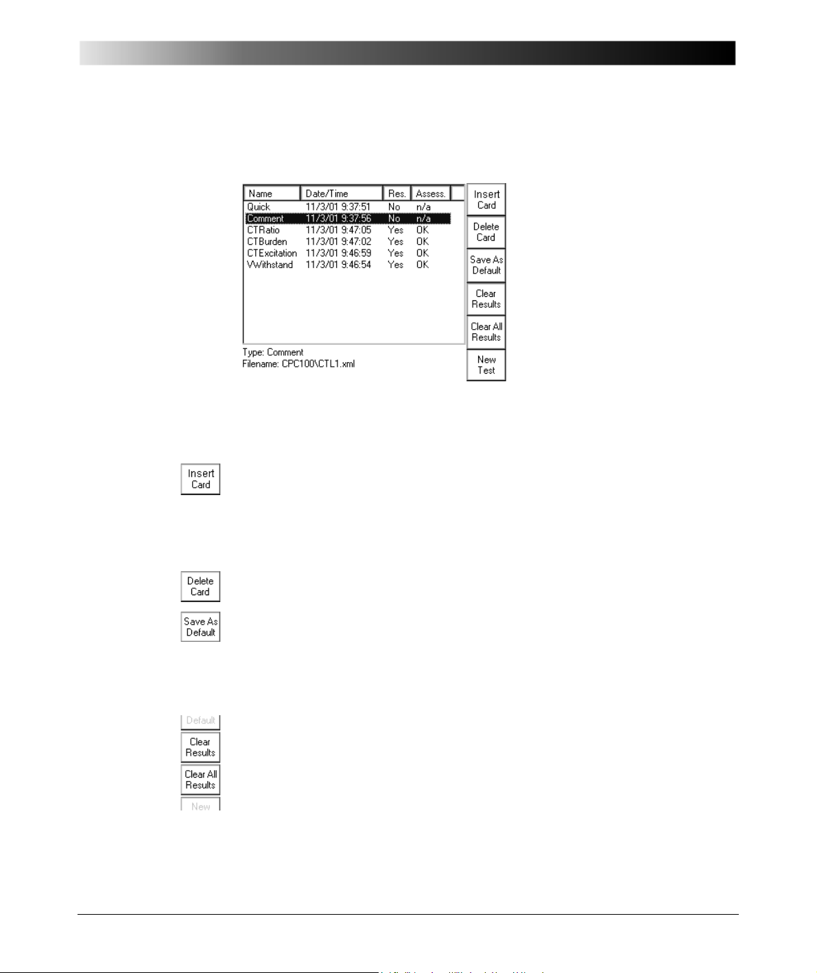
Figure 21:
Test Procedure
Overview
Introduction
Test Procedure Overview
The Test Procedure Overview lists all test cards of the currently active test
procedure in a list box showing the card’s name, its creation date and time,
whether test results are available and the test card’s assessment status.
Pressing Insert Card switches to the Insert a new test card dialog. After
inserting a new test card, the software automatically switches to the Test Card
View, inserting the test card of your choice after the last selected test card in the
Test Card View.
Pressing Esc at Insert a new test card brings you back to the previous view
without inserting a new test card.
Delete Card deletes the currently highlighted test card from the test procedure.
With Save As Default, Test Procedure Overview provides a function to save the
current test procedure as the test procedure default, that is the default the
CPC 100 software will start with in future.
To learn more about defaults, refer to section ”Creating Defaults and Templates”
on page 44 of this chapter.
Unlike in Test Card View, where all context-dependent menu keys apply for that
particular card only, the Test Procedure Overview has an additional menu item
that applies for all test cards: whereas Clear Results clears the test results of
the currently highlighted test card only ("Comment" in Figure 21), Clear All
Results applies to all test cards, that is, clears the results of all cards listed in
the Test Procedure Overview.
After both Clear Results and Clear All Results, re-start the test in the Test Card
View by pressing the I/O (test start/stop) push-button.
2 - 31
Page 62
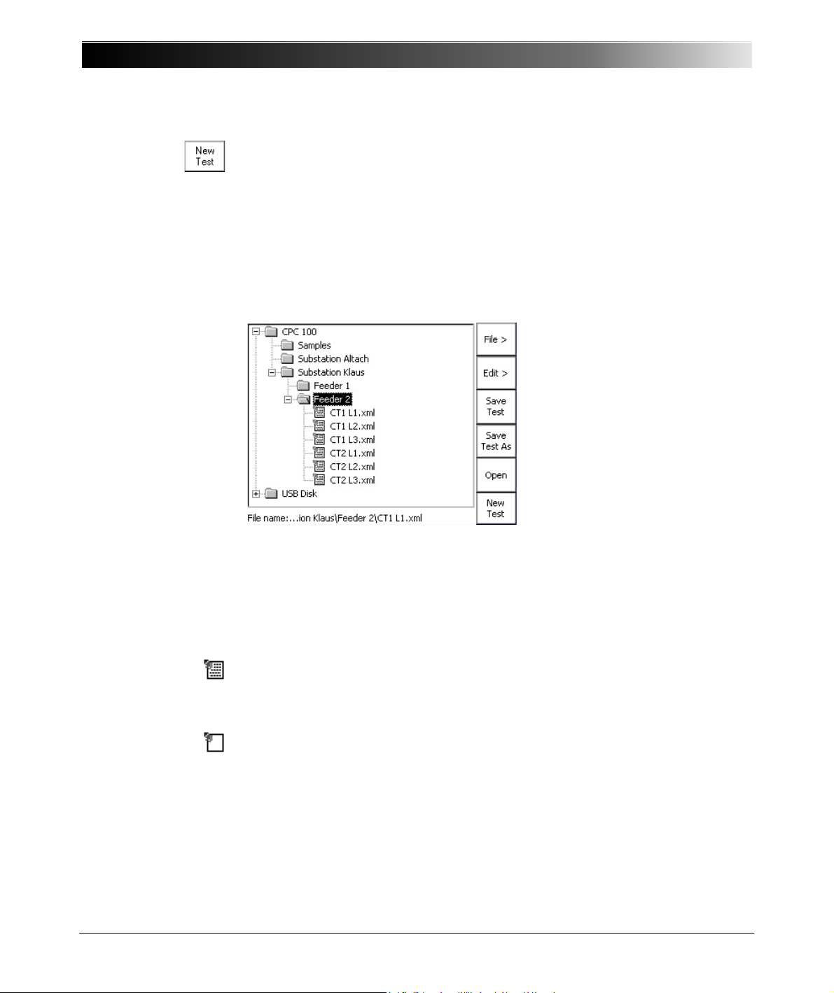
CPC 100 V 1.44
Automatically switches back to the Test Card View, and opens the test
procedure default. If the current test procedure contains unsaved data, you will
be asked whether or not you want to save them before you proceed.
The CPC 100 File System
The CPC 100 File Operations resemble the functionality known from, for
example, the Windows Explorer. File Operations comprises a File and an Edit
submenu with additional menu items as well as an Open and various Save...
functions.
2 - 32
The highest hierarchical level of the CPC 100 file system, the "root", is named
CPC 100. Below this, you can create additional folders in a tree-structure of your
choice, save tests in these folders, and carry out file operations, such as open,
save, rename, copy, paste etc. For CPC 100 V1 units with a USB memory stick
plugged in, a second tree root USB Disk is displayed as shown above.
The CPC 100 file system differentiates two file types:
name.xml A test procedure with all of its test cards and specific settings.
An .xml file may also contain test results and assessments that
were stored together with the settings as report in the CPC 100
file system for archiving purposes.
name.xmt Test procedure template, that is, a user-defined template
containing one or more test cards with all of their specific test
settings but without test results.
Note: The file containing the up-to-date measurements should be saved
regularly. If the test unit is switched off, or in case of a power outage, all unsaved
measurements will be lost.
Page 63
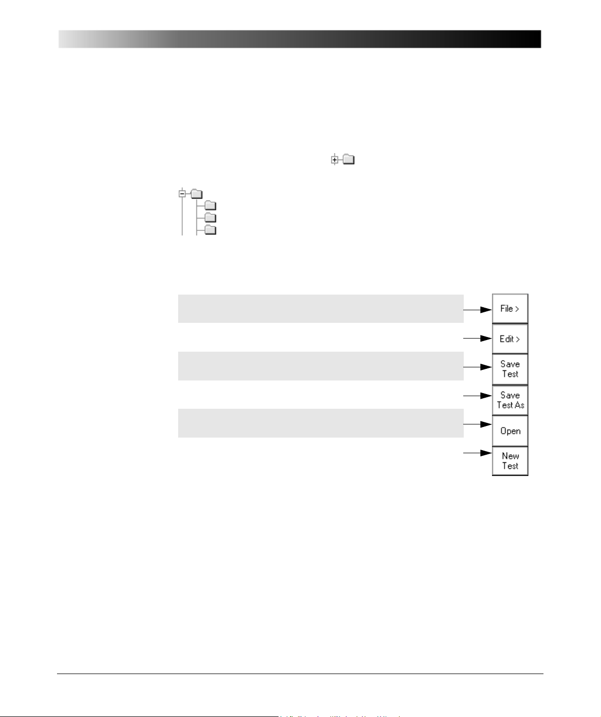
Introduction
Opens the submenu File (refer to page 2-34)
Opens the submenu Edit (refer to page 2-34)
Saves the currently open test, that is, the test card(s)
previously opened in the Test Card View (refer to Note below).
Opens the String Editor. You can save the currently open test
under a new name of your choice (15 characters max.).
Use the handwheel or the Up/ Down keys to select a test, and
press Open to open it. Changes to Test Card View.
Closes the current test card(s), changes to Test Card View and
opens the test procedure default.
Navigating Through the File System
Select, that is, highlight, a test or a folder using the handwheel or the Up/ Down
keys.
To expand a collapsed folder tree , highlight it, and press either the
handwheel or Enter.
The folder expands and displays its subfolders (if any) and the tests
it contains.
Browse to the test card of your choice, and when its highlighted press
the handwheel or Enter.
The Menus
Main File Operations menu
Note: Unlike the other menu items, the two Save... functions of the main File
Operations menu directly effect the currently open test, i.e., the test procedure
that was composed in the Test Card View, or the test that was loaded in the
CPC 100 file system beforehand.
Therefore, pressing Save, for example, does not save the test that you may
have highlighted in the folder tree, but the one that is currently open.
2 - 33
Page 64
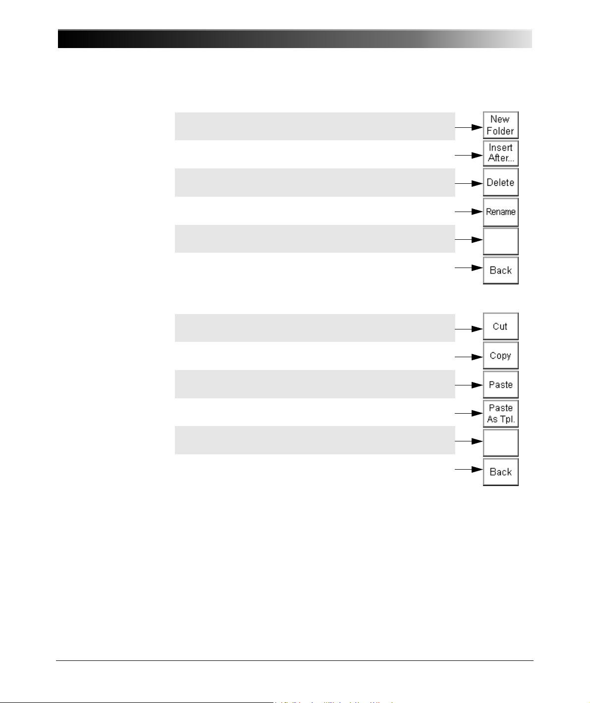
CPC 100 V 1.44
Opens the String Editor. You can create a new folder with any
name of your choice.
Appends the contents of a test file (.xml) or template (.xmt) of
your choice to the currently open test.
Deletes the currently selected test or folder from the CPC 100
disk space.
Opens the String Editor that enables you to rename the current
test to any new name of your choice.
(for future use)
Closes the submenu and returns to the main File Operations
menu.
Select the test of your choice. Press Cut to put the selected
test or folder to the Clipboard. Proceed with Paste...
Select the test of your choice. Press Copy to copy test or
folder to the CPC 100 Clipboard. Proceed with Paste...
Move to the destination folder of your choice. Press Paste to
insert the contents of the CPC 100 Clipboard to this folder.
Press Paste As Templ. to make the contents of the CPC 100
Clipboard a test procedure template.
(for future use)
Closes the Edit submenu and returns to the main File
Operations menu.
Submenu File
Submenu Edit
Note: If a folder is cut or copied to the Clipboard, the selection is recursive, that
is, all of its subfolders will also be put to the Clipboard.
Cutting or copying a test or folder, and trying to paste it in the same location,
2 - 34
opens the String Editor.
Since a test or folder cannot exist twice under the same name at the same
location, determine a new name for it using the String Editor.
For more information about the String Editor, please refer to ”The String Editor”
in chapter 9.
Page 65
Table 1:
Instantiation procedures
Introduction
Options
Note: Changes made in the Options view are automatically saved when the
view is changed (for example when Options is left to change to Test Card View).
Alternatively, changes can be saved instantly by pressing Save Options.
Upon a power supply loss or an accidental switching off of the CPC 100,
unsaved changes are lost, and the old values are restored.
Device Setup
The Device Setup tab in the Options view allows you to change the settings of
all test cards of the test procedure running on the CPC 100 and all test cards
inserted afterwards. The test cards can be instantiated in different ways and for
different purposes. Table 1: ”Instantiation procedures” below displays the
instantiation procedures and the associated default values.
Procedure Default values
New test card Booster, clamp and default frequency
set in the Options view
New test card saved as default Booster and clamp set in the Options
view
New test procedure from template
(*.xmt)
New procedure from report (*.xml) Booster, clamp and frequency remain
Booster, clamp and frequency remain
as defined in the template
as defined in the report
Because the settings of a test card containing results cannot be changed, the
settings made at the Device Setup tab in the Options view apply only to new
test cards if the currently loaded procedure contains results. To change the
settings of a test procedure containing results (for example, after pressing the
Keep Results menu key or after loading a file), clear the results by pressing the
Clear Results menu key in all test cards before setting the test procedure in the
Options view.
It is strongly recommended to set the test cards using the Options view. In wellfounded cases, you can alternatively set a test card individually using the
Settings menu key (see ”Settings Page” on page 28 of this chapter).
2 - 35
Page 66
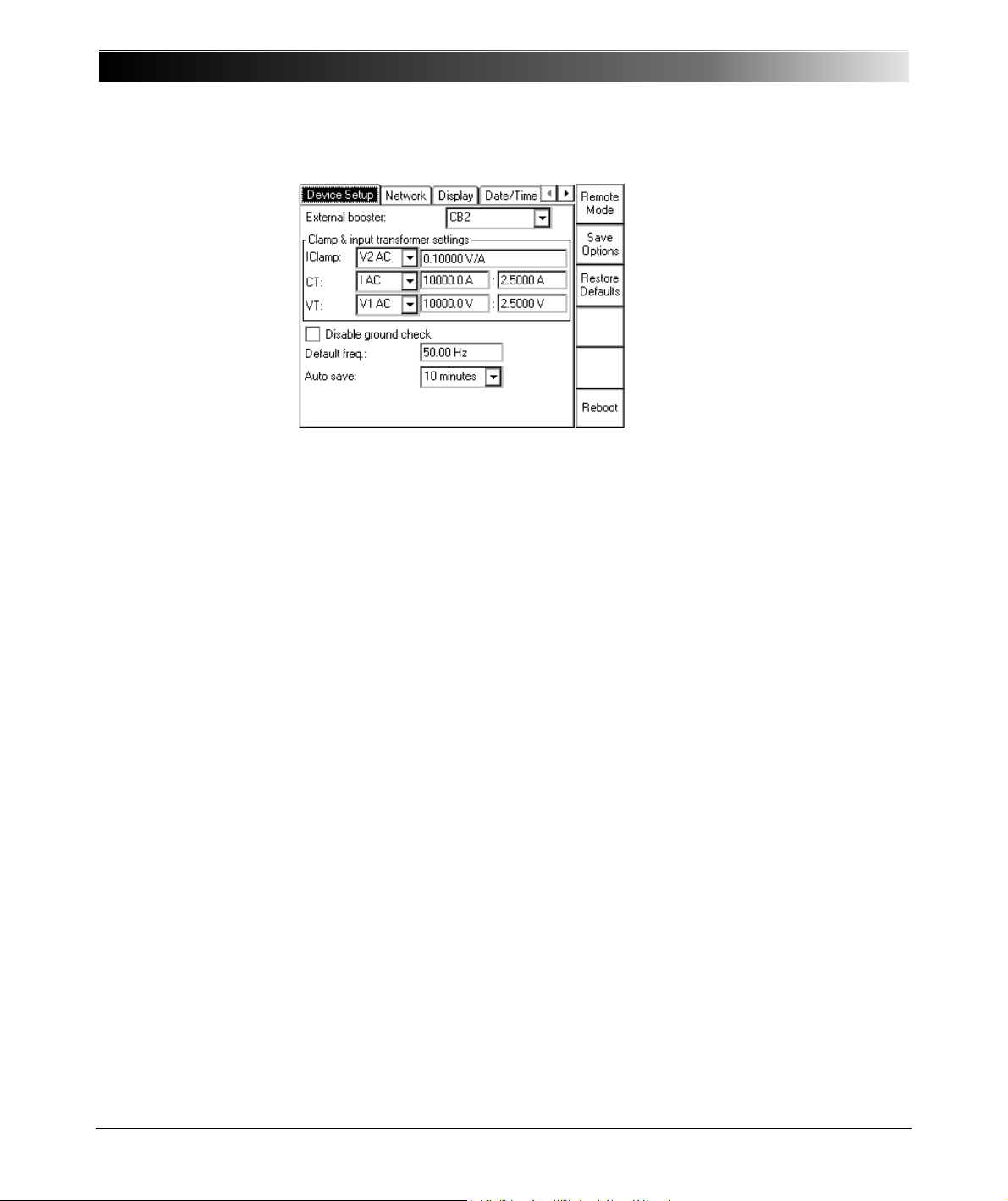
CPC 100 V 1.44
Figure 22:
Options tab Device
Setup
External booster
The "External booster" combo box allows to set the external booster:
• CB2 for the CP CB2 current booster
• CU20 for the CP CU20 coupling unit
• CU1 for the CP CU1 coupling unit
For the default value associated with different instantiation procedures, see
Table 1: ”Instantiation procedures” on page 35.
Clamp & input transformer settings
When an input is not connected to the device under test directly but using a
current clamp, a CT or a VT, the ratio of these devices can be set here.
The Clamp & input transformer settings group box displays and, if required,
allows you to change settings for external devices:
• IClamp for the current clamp parameters
• CT for the transformation ratio of the current transformer
• VT for the transformation ratio of the voltage transformer
By default, the transformation ratios of the current and voltage transformers for
the selected external device are preset. For the default value associated with
different instantiation procedures, see Table 1: ”Instantiation procedures” on
page 35.
2 - 36
Page 67

Introduction
Disable ground check
Warning: Operating the CPC 100 with the "Disable ground check" check box
selected can cause injury or possibly death of the operating staff if the power
supply is not metallically separated and the PE (protective connection) is
defective.
An error message (313) appears if either the PE connection is defective or the
power supply has no galvanic connection to ground. In this case, make sure that
the PE connection is intact. If the PE connection is intact and the error message
still appears, select the "Disable ground check" check box.
Note: After the CPC 100 has been rebooted, the "Disable ground check" check
box is cleared for safety reasons.
Default freq.
The "Default freq." data entry field allows you to enter the default frequency. For
the default value associated with different instantiation procedures, see
”Instantiation procedures” on page 35 of this chapter.
Auto Save
As the name implies, the Auto Save feature automatically saves the current test
settings in fixed intervals. These intervals can be set in the "Auto Save" box.
There are three time intervals available (10, 30 or 60 minutes), and the option
OFF which disables Auto Save.
Auto Save saves all actual data to a file named lastmeas.xml. So depending
on the set time interval, in case of a system crash, lastmeas.xml may contain
more actual data than the last manually saved test. The file is created during the
next booting process.
When Auto Save saves test settings, it pops up a dialog notifying you about it.
Auto Save works in Test Procedure Overview, File Operations or Options
without any restrictions. In Test Card View, Auto Save does not work as long as
a test is running, or as long as inputs are measured (for example, in Quick).
In a case like this, Auto Save repeats the attempt to save the test settings in
intervals until it succeeds, that is, until the test is finished and it can save the
data. After this, Auto Save returns to the set time interval.
2 - 37
Page 68

CPC 100 V 1.44
Restore Defaults
Note: Pressing the Restore defaults menu key resets all user-specific settings
made in the CPC 100 software to factory-defined defaults including:
• the test card defaults
• the test procedure default
• all settings made at the Device Setup tab (sets external booster to CB2, sets
CT and VT to "OFF", and sets the value in the "Default freq." data entry field
to 50 Hz)
•the String Editor’s template strings (refer to ”The Template Phrases” on page
9-4).
2 - 38
Page 69
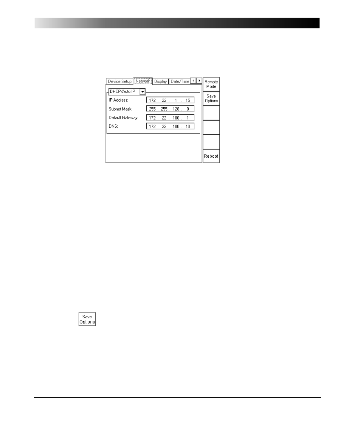
Figure 23:
Options tab Network
Introduction
Network
Via the built-in ePC, the CPC 100 can be accessed from a stand-alone PC, for
example, a notebook and via a PC network. At the Network tab the
communication settings are specified.
In the combo box select between
DHCP/Auto IP Configures all communication parameters automatically;
the DHCP server will do it for you or it will be done via the
Auto IP mechanism.
The data entry fields for IP address, Subnet Mask, Default
Gateway and DNS are read-only, no data can be entered.
This is the recommended setting.
Static IP Configure the communication parameters manually by
entering the values into the data entry fields using the softtouch keys.
Section ”CPC 100 in a Network” in chapter 10 explains in detail how to connect
the CPC 100 to either a stand-alone PC or a PC network, and how to configure
such a connection.
Once the communication parameters are configured, press Save Options to
save them to the Windows Registry.
For a change to come into effect, the operating system needs to be re-booted,
that is, the CPC 100 restarted.
2 - 39
Page 70
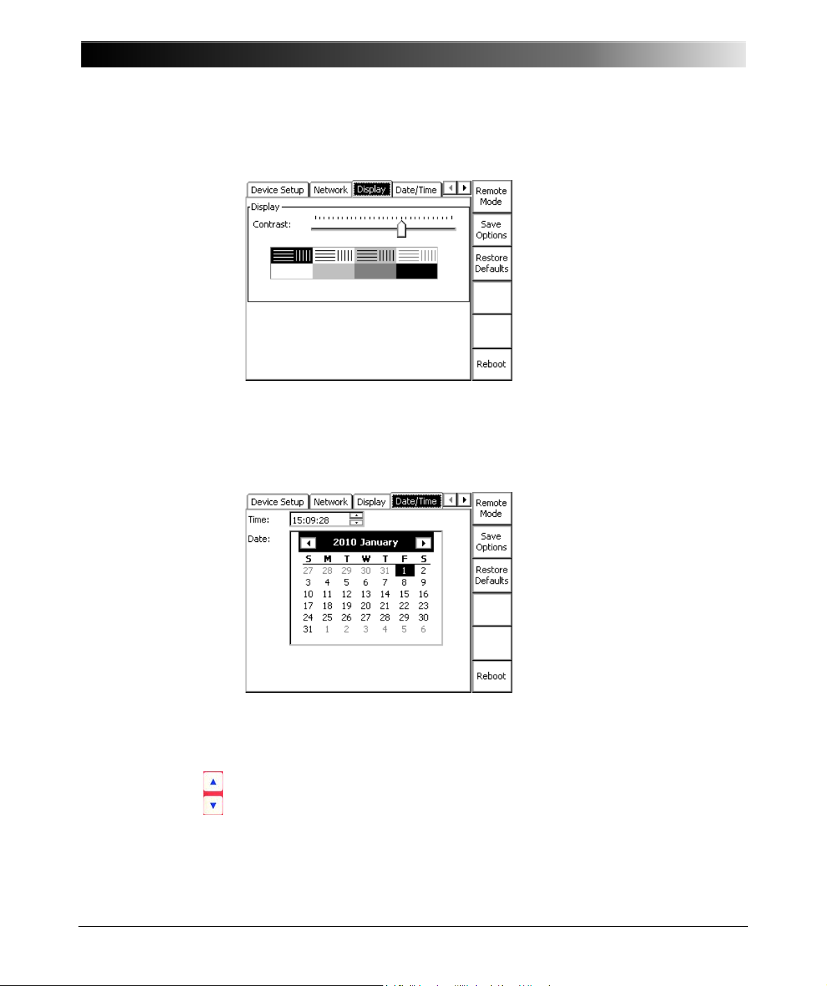
CPC 100 V 1.44
Figure 24:
Options tab Display
Display
The "sliding" regulator brightens or darkens the monitor display and the contrast
within it. Adding contrast increases the difference in shading between areas.
Date / Time
Figure 25:
Options tab Date/Time
Specify the system’s date and time here.
To set the time
• put the focus onto the “Time:” field using the handwheel
• use the Up / Down keys to select between hours, minutes and seconds
• turn the handwheel to increase or decrease the value
• press the handwheel to acknowledge your entry
Changing the current date and time does not require pressing Save Options.
2 - 40
Page 71
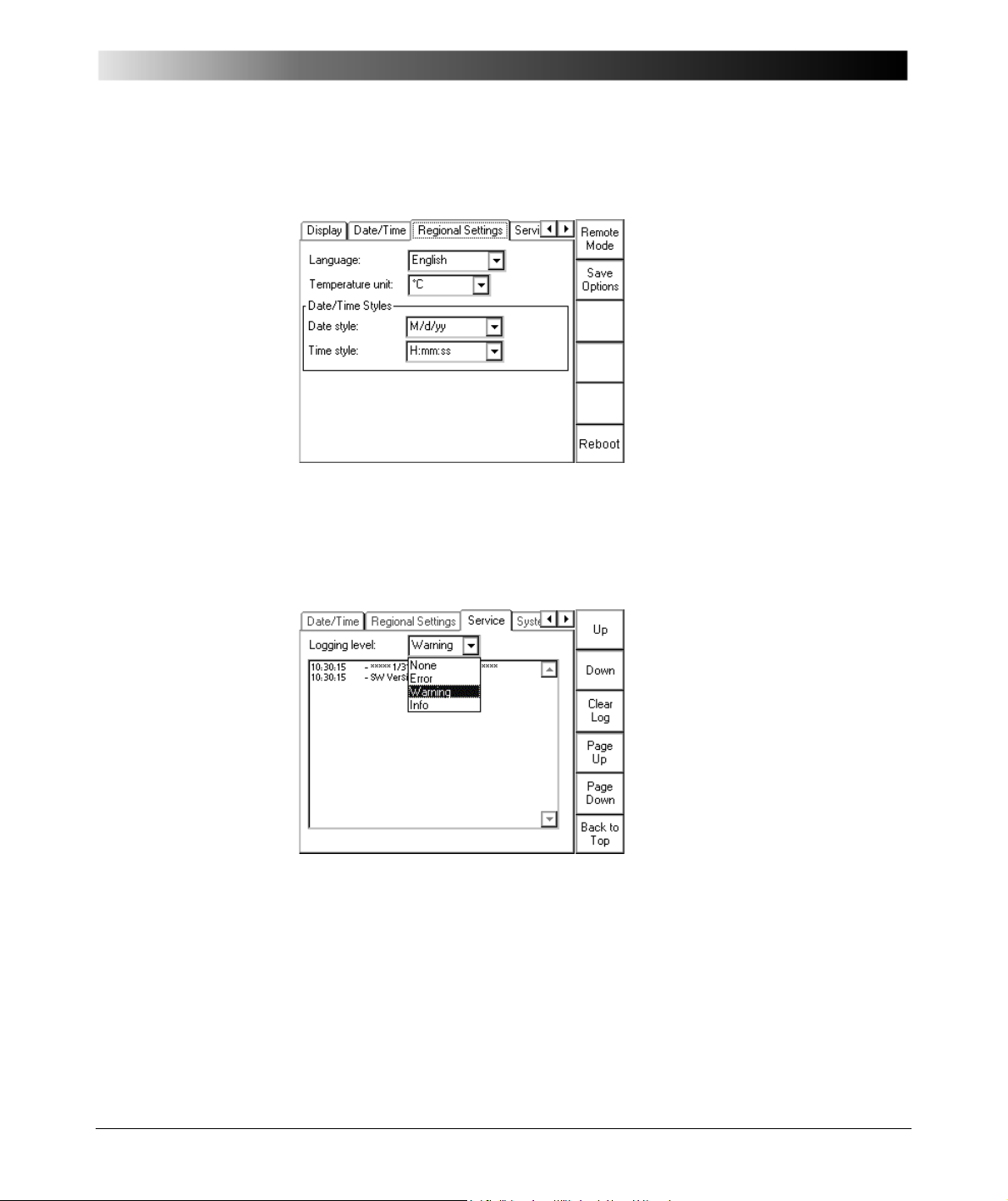
Figure 26:
Options tab Regional
Settings
Introduction
Regional Settings
Choose a regional setting for language, temperature unit, date and time style.
These settings affect the way the CPC 100 software displays and sort dates,
times, numbers and decimal points.
Figure 27:
Options tab Service
Service
During operation, the CPC 100 creates a logfile with a user-definable logging
level (see below).
Every time the CPC 100 is switched on, it generates a new logfile, and saves the
existing one as the "previous" logfile. This way, the occurrences of the previous
and the current session can be viewed.
2 - 41
Page 72

CPC 100 V 1.44
The logging level specifies the occurrences to be recorded in the logfile:
Logging level: Records
None nothing
Error internal errors, hardware errors, operational errors,
overload conditions etc.
Warning uncritical errors such as over-temperature, malfunction
etc.
Info additional operational information about the CPC 100.
This setting is suggested if the operator suspects, for
example, an incorrect functioning or an operational
malfunction of the CPC 100. This setting records every
relevant operational activity of the CPC 100.
The logfile can then be sent to OMICRON electronics for
diagnosis.
The default setting is Warning.
Note: The logging levels are hierarchical, that is, if logging level Warning is set,
Errors are also recorded, or if Info is set, the logging levels Warning and Error
also apply.
If the logfile gets quite long, use either the scroll bar or the buttons Page Up/
Page Down to navigate up and down in the list of logged occurrences.
Clear Log deletes all logfile entries and starts recording occurrences anew.
2 - 42
Page 73
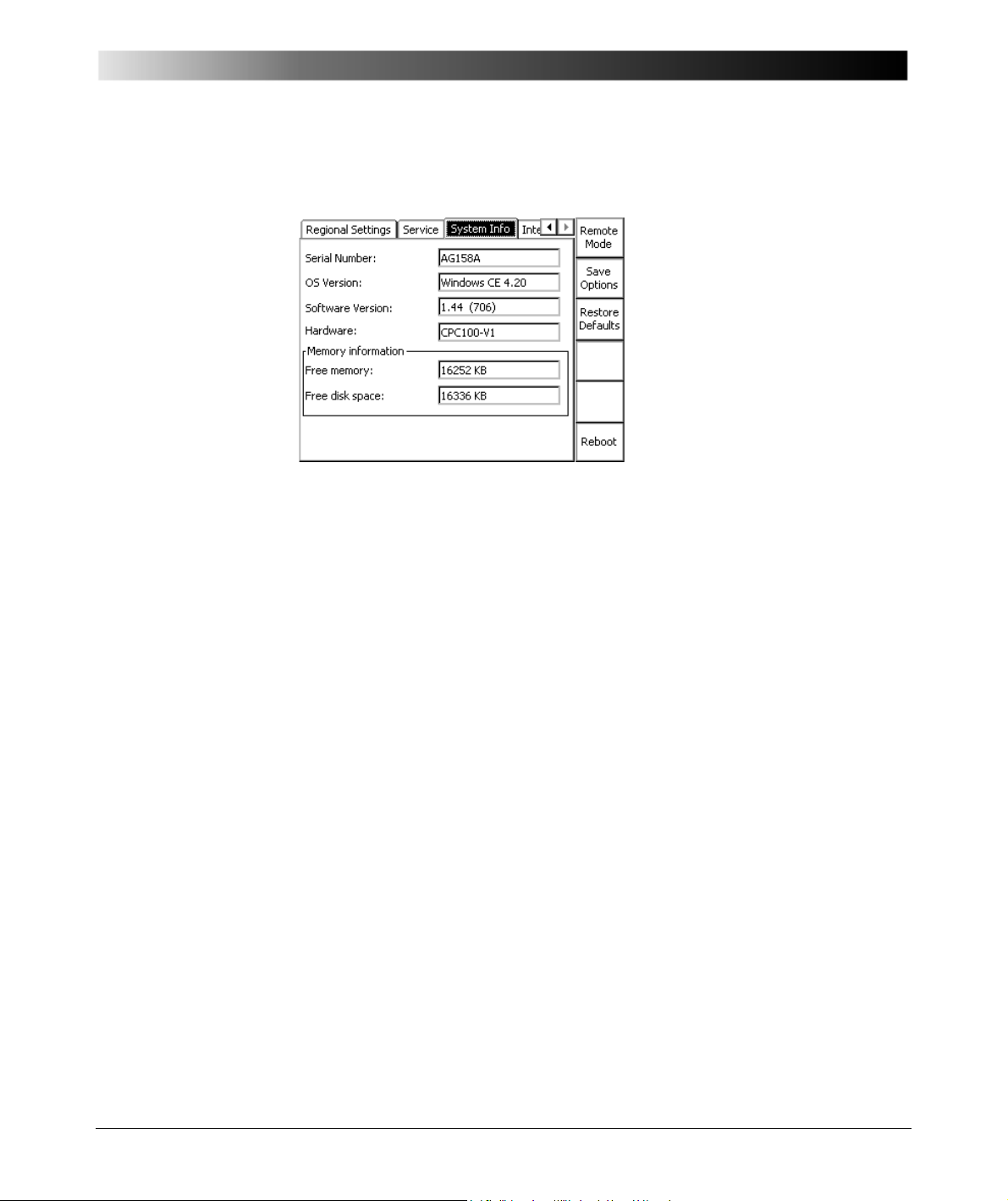
Figure 28:
Options tab System
Info
Introduction
System Info
Displays the following system information:
Serial Number: CPC 100 serial number
OS Version: operating system with version
Software Version: CPC 100 software version
Hardware: CPC 100 hardware
The last two positions indicate the CPC 100 hardware
version.
Free memory: currently available free memory (RAM)
Free disk space: free disk space
2 - 43
Page 74
CPC 100 V 1.44
Creating Defaults and Templates
The CPC 100 software differentiates three types of templates:
1. test card default
2. test procedure default (default upon start-up)
3. test procedure templates.
Note: Pressing the Restore Defaults menu key at the Options tab Device
Setup resets all user-specific settings made in the CPC 100 software to factory-
defined defaults.
This includes the test card defaults and the test procedure default.
Test Card Default
Rather than repeatedly filling out blank test cards with frequently used settings,
any test card with its actual settings can be made a test card default for that
particular type of card, for example, filling out a Quick test card with values and
pressing Save As Default makes this card the new Quick test card default.
Note: The actual function of the context-dependent menu keys depends on the
selected view, test mode, test card and selected UI element.
To make the function Save As Default visible, the focus
(
Glossary) must be set onto the test card tab designation, for
example, Quick.
Each card of this type, here Quick, that will later be inserted to a test procedure
will already hold these new settings.
Note: A test card default contains user-defined settings, not test results.
In the CPC 100 file system, a test card default is not visible as a "file" (refer to
”The CPC 100 File System” on page 2-32).
2 - 44
Page 75

Introduction
Test Procedure Default
The CPC 100 software always starts with the test procedure default. Initially,
that is, as long as no user-defined test procedure default is created, this default
contains one empty Quick test card. However, this default can be customized
according to your specific requirements with as many test cards as needed and
of all types of your choice.
Note: With the CPC 100 V0, the number of test cards in one test procedure
should be limited to 15 to avoid memory problems. The CPC 100 V1 allows
using more test cards in one test procedure but we recommend not to use more
than 15 test cards to keep the tests clearly structured.
If you need more test cards in one test procedure, we recommend not to save
all cards in one, for example, the test procedure default, but to combine a smaller
number of cards to logical groups, and to save these logical groups as test
procedure templates with individual names (refer to ”Test Procedure Templates”
on page 45 of this chapter).
In the CPC 100 file system, the test procedure default is not visible as a "file"
(refer to ”The CPC 100 File System” on page 2-32).
2 - 45
Page 76
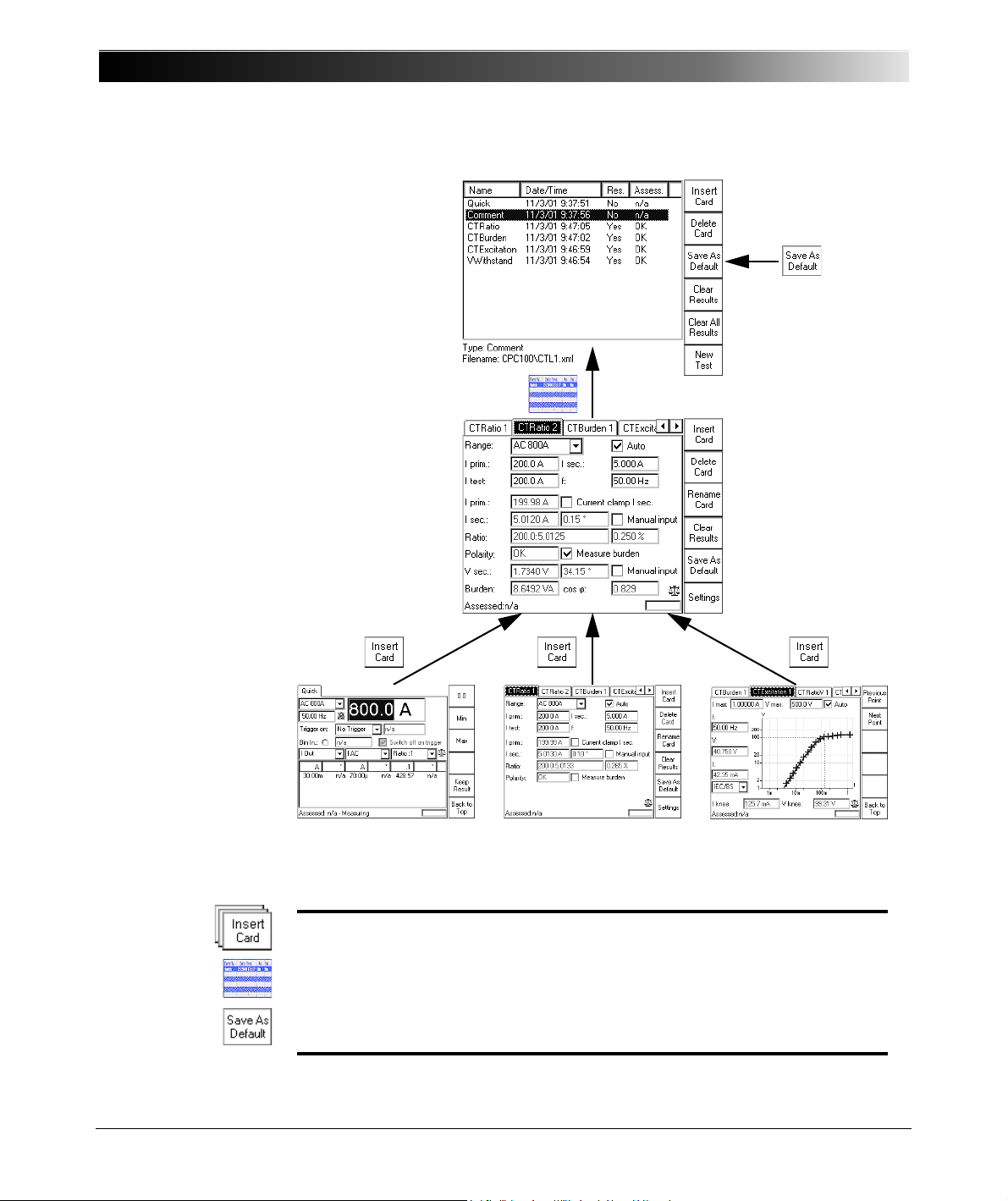
test card 1 test card 2 test card 3
A number of test
cards are inserted
to the currently
open test
procedure.
Switch to the Test
Procedure
Overview…
… and press
to make this test
procedure the new
test procedure
default.
Step 1
Step 2
Step 3
CPC 100 V 1.44
Figure 29:
Creating a user-defined
default by customizing
the test procedure
default
Step 1: In the test card view, insert as many test cards as needed to the
currently open test procedure default.
Step 2: At the CPC 100 front panel view selector, switch to the Test
Procedure Overview.
Step 3: Press Save As Default to make this test procedure the new test
procedure default.
2 - 46
Page 77

Introduction
Test Procedure Templates
A test procedure template is a user-defined test procedure, and can be created
from any test procedure that was saved to the CPC 100 file system beforehand
(a name.xml file; refer to ”The CPC 100 File System” on page 2-32).
To create a test procedure template from an .xml file
• go to "File Operations"
• highlight the name.xml file of your choice
•select Edit | Copy to copy the test procedure
•select Paste As Templ.
• a file name.xmt is generated.
If this file name.xmt already exists, you will be asked whether or not to
overwrite the existing file.
If you answer this question with No, the String Editor opens (refer to ”The
String Editor” in chapter 9).
Give the test procedure template a name of your choice (max. 15
characters), and select OK. The file name extension .xmt is appended
automatically.
In this process, the settings of the original name.xml file are taken over to the
newly created test procedure template name.xmt. The test results, however,
are not taken over.
The original file name.xml remains unchanged.
2 - 47
Page 78

CPC 100 V 1.44
Installation of the CPC 100 Toolset
The CPC 100 Toolset and its installation program Setup Wizard are stored on
the CPC 100 Toolset DVD. The installation comprises the CPC 100 Start Page,
Primary Test Manager, CPC Excel File Loader, Excel Templates (for specific
applications), CPC Editor (to create and edit CPC 100 test templates),
OMICRON Device Browser, CPC 100 Upgrade Packages, Manuals and
Application Notes, Foxit PDF Reader (redistributable), OMICRON News, and
Product Application Videos.
To start the installation:
1. Quit all other major programs running on your computer.
2. Insert the CPC 100 Toolset DVD into your computer’s DVD drive. The Setup
Wizard starts automatically displaying the CPC 100 Toolset start screen.
Note: Should the Setup Wizard not start automatically a few seconds after the
DVD has been inserted into the DVD drive, launch the Windows Explorer and
double-click setup.exe on the CPC 100 Toolset DVD.
3. On the start screen, click the language of your choice and follow the onscreen instructions.
Note: The selected language affects all subsequent dialog boxes and all
installed files.
Computer Requirements
Minimum Computer Requirements
• Pentium 200MHz
•64MB RAM
•DVD drive
• Ethernet connection
• Windows 2000/ XP/Vista/Windows 7
Please note that Windows 95 is not supported.
Note: All Windows operating systems require administrative rights on your local
machine for installation.
Recommended Computer Features
• Pentium 233 MHz or higher
• 128 MB or more RAM
2 - 48
Page 79

Introduction
Putting the CPC 100 into Operation
Note: Before setting the CPC 100 into operation and carrying out a test, it is
essential that you have read and understood the section ”Safety Instructions for
the CPC 100 and its Accessories” on page 1-5.
Always be aware that all AC and DC output sockets of the CPC 100 can carry
life-hazardous voltage potential and provide life-hazardous currents.
Safety Aspects
We strongly advise you to obey the following legal safety aspects:
• Tests with such high voltages and currents must only be carried out by
authorized and qualified personnel.
• Personnel receiving training, instructions, directions, or education on highvoltage/current tests should remain under the constant supervision of an
experienced operator while working with the equipment. The instructions
have to be renewed at least once per year.
• The instructions must be available in written form and signed by each person
assigned to do high-voltage/ current tests.
Preparations in Substation
Warning: Prior to connecting a test object to the CPC 100, the following steps
need to be carried out by an authorized employee of the utility.
• Turn off and disconnect the high voltage from the test object.
• Protect yourself and your working environment against an accidental reconnection of high voltage by other persons and circumstances.
• Verify a safe isolation of the test object.
• Earth-connect and shorten out the test object’s terminals using a grounding
set.
• Protect yourself and your working environment with a suitable protection
against other (possibly live) circuits.
• Protect others from accessing the dangerous area and accidentally touching
live parts by setting up a suitable barrier and, if applicable, warning lights.
• If there is a longer distance between the location of the CPC 100 and the
area of danger (that is, the test object), a second person with an additional
"Emergency Stop" button is required.
2 - 49
Page 80
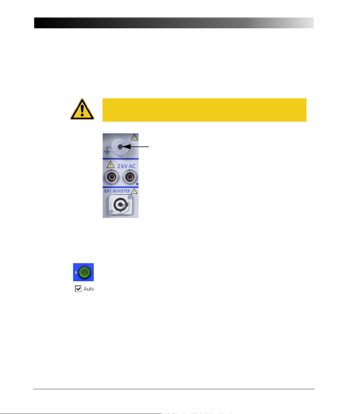
CPC 100 V 1.44
Connect the CPC 100
grounding terminal to
substation ground.
Principle Steps to Carry Out a Test with the CPC 100
1. Verify that the substation is prepared accordingly and you comply with all
safety regulations.
2.
Caution: Connect the CPC 100 grounding terminal to the substation ground.
Use a wire with a cross-section of
high voltage.
6 mm², otherwise the housing may feed
2 - 50
3. Connect the CPC 100 to the mains power supply using the provided cable.
4. With the test object grounded and shorted out, connect the CPC 100 to the
test object according to your requirements.
5. Remove the grounding set from the test object.
6. Turn on the CPC 100 at its POWER switch at the left-hand side.
The green warning light "O" lights up, showing that none of the CPC 100
outputs carries a dangerous voltage or current yet.
7. Set up your test in the CPC 100 software, and, where applicable, determine
whether you want to perform an automatic or a manual test.
The following chapters of this manual comprise an example for each
available test.
For a detailed description of how to use the software refer to section ”How to
Use the CPC 100 Software” on page 17 of this chapter.
8. Once all test cards are prepared and the parameters set, make sure the
safety key lock is in position "release" (horizontal).
Page 81
Introduction
9. Start the test by pressing the green I/ O (test start /stop) push-button on the
CPC 100 front panel.
Notes: • A test can only be started in the Test Card View and with all
preconditions met (refer to ”Starting a Test” on page 29 of this
chapter).
• If voltages
(test start/stop) push-button for the first time a warning
message appears on the screen.
Only after the I/O push-button is pressed a second time, the
voltage is applied to the CPC 100 output.
• An error message (313) appears if either the PE connection is
defective or the power supply has no galvanic connection to
ground. In this case, make sure that the PE connection is intact.
If the PE connection is intact and the error message still
appears, select the "Disable ground check" check box at the
Device Setup tab in the Options view (see ”Device Setup” on
page 2-35).
1 kV are to be applied, after pressing the I/O
Rather than starting a test and activating the outputs, pressing
the I/O (test start/stop) push-button will then pop up a message
box notifying you about this problem.
10.If a potentially hazardous voltage and/or current level is applied to the
CPC 100 outputs, the red signal red light "I" starts flashing.
11.After testing, switch off the high voltage or current immediately with the I/O
(test start/stop) push-button.
12.If you do not use the CPC 100 anymore, turn the safety key to "lock" (vertical)
and remove the key to avoid anybody accidentally turning on the high voltage
or current.
Note: After
only when the CPC 100 green warning light is on and the red one off, switch
off the safety key lock and take off its key.
13.After turning off the CPC 100 outputs, earth-connect and short-circuit the
test object’s terminals again using a grounding set.
14.Remove the connection between the CPC 100 and the test object.
Warning: Never touch any metallic terminals and / housing components
without a visible ground connection!
turning off the high voltage or current observe the warning lights:
2 - 51
Page 82

CPC 100 V 1.44
2 - 52
Page 83
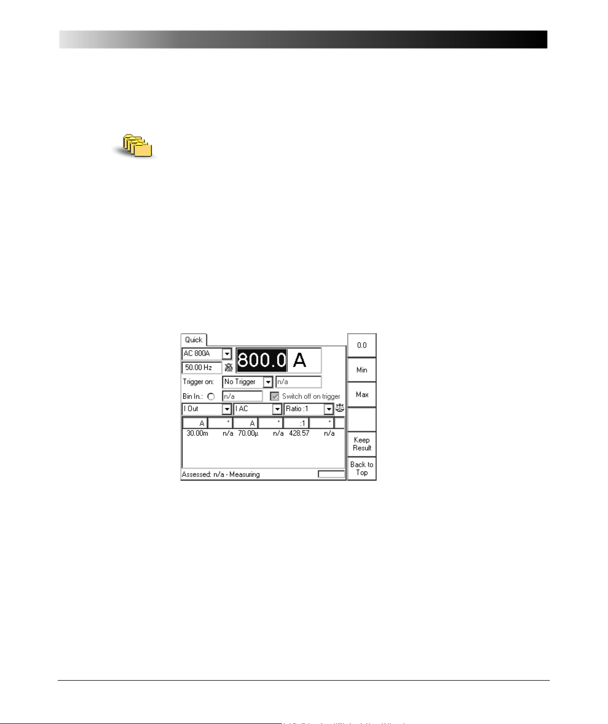
Figure 1:
Quick test card
Getting Started with Quick
Getting Started with Quick
Contents of this section
About Quick..................................................................................... page 3-1
Measurement Settings .................................................................... page 3-3
The Frequency-Selective Measurement .................................... page 3-6
Power Output Settings .................................................................... page 3-7
Trigger Settings............................................................................. page 3-10
About Quick
Quick is the most basic mode to operate all of the CPC 100 outputs in a manual-
like mode with front panel control.
The CPC 100 starts in the Test Card View (refer to ”Test Card View” on page 2-
22) with the test procedure default. Initially, the test procedure default contains
one empty Quick test card. However, this template can be customized
according to your specific requirements with as many test cards as needed and
of all types of your choice.
By creating a user-defined test procedure default, the CPC 100 starts up loading
your most frequently used test cards already containing specific values.
To learn more about defining such a template, refer to ”Creating Defaults and
Templates” on page 2-44.
3 - 1
Page 84
CPC 100 V 1.44
Quick starts in "measuring" state with de-activated outputs, displaying the
measured values in the measurement table of the Quick test card.
The measurements as well as the indication of the binary input’s signal status
(refer to ”Bin.In:” on page 11 of this chapter) are updated with an interval of
approx. 0.5 s.
After having set all necessary parameters (more about this in the following
sections), press the I/ O (test start / stop) push-button. The Quick test card
enters the "on" state, the set power output value is switched to the CPC 100
outputs, the measuring continues.
Pressing the Quick test card menu key Keep Results saves the currently
measured values and "freezes" their display in the measurement table. Both the
"measuring" and the "on" state remain active, the measurement continues in a
new line of the measurement table.
While in "on" state, pressing the I/ O (test start / stop) push-button terminates the
test. The CPC 100 outputs are turned off, and Quick returns to the "measuring"
mode.
Caution: When testing capacitive test objects using voltages 500 V, make
sure that the test object’s capacity does not exceed 25 nF.
Together with the test object’s capacity, the leakage inductance of the
CPC 100 internal output transformer forms a series resonant circuit. Especially
at frequencies > 50 / 60 Hz this may result in voltage superelevation.
Caution: Never use Quick to measure the resistance of windings with a high
inductance because turning off the DC source results in life-threatening voltage
levels.
For this kind of measurement only use the special winding resistance test card
RWinding!
Pressing the Settings menu key opens the Settings page. The Settings page
allows setting the test cards individually. As a rule, do not use the Settings page
but the Device Setup tab in the Options view (see ”Device Setup” on page 2-
35) to set the test cards. For more information, see ”Settings Page” on page 2-
28.
3 - 2
Page 85
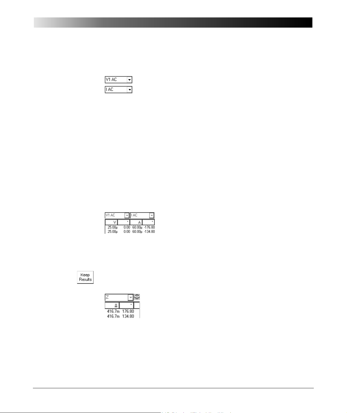
Measurement Settings
Getting Started with Quick
Measured quantities (
Combo boxes to select the first and second quantity to
measure. Possible choices at each combo box:
•V1AC
•V1ACsel
•V2AC
•V2ACsel
•VOut
•VOutsel
•VT
•VTsel
•IAC
• I AC sel
V Out and I Out represent the measured values of the
actual output range.
Each combo box has two corresponding cells in the
measurement table below that display the measured
values, where possible; otherwise"n/a" is displayed.
1. sel = frequency-selective. To learn more about frequency-selective measurements, refer to ”The
Frequency-Selective Measurement” on page 6 of this chapter.
1
Glossary)
•IOut
•IOutsel
• I Clamp
• I Clamp sel
•CT
•CTsel
•VDC
•IDC
• f V1 AC
•fOut
Note: Not all measured quantities are available in all output ranges.
After having pressed Keep Results, the combo boxes of the measured
quantities are disabled, that is, the quantities cannot be changed.
Calculated value
Both the items to select from in this combo box and the
corresponding display at the measurement table below
depend on the selected measured quantities.
In this combo box you determine what the measurement
table displays (see Table ”Display of calculated value in
measurement table” on page 4 of this chapter).
3 - 3
Page 86
CPC 100 V 1.44
Table 1:
Display of calculated
value in measurement
table
Measured
quantities
(m1) (m2)
V V Ratio:1, Ratio : 5, Diff:
Display of calculated value in
measurement table
Ratio m1/m2 and phase angle
(if phase angles are available; else "n/ a"),
and differences
I I Ratio :1, Ratio :5, Diff:
Ratio m1/m2 and phase angle
(if phase angles are available; else "n/ a"),
and differences
V I For AC: Z or R, X
Impedance Z (magnitude in
angle
in °) or R and X in
For DC: R
Resistance R (in
else "n/a"
VI
For AC: P, Q, S
Real power P (in W) and cos
power S (in VA) and cos
Q (in var) and cos
For DC: P
Real power P (in W)
else "n/a"
U and
I and
m1 - m2
.
U
m1 - m2
.
I
and phase
, apparent
, reactive power
3 - 4
Page 87
Getting Started with Quick
Measured
quantities
(m1) (m2)
V I Rs, Ls or Rp, Cp:
Resistance R and either inductance Ls in H
(series equivalent circuit) or capacity Cp
in F (parallel equivalent circuit).
This is just another representation of the
impedance Z
in its components.
Using Rs, Ls, the impedance is given by:
Z
frequency is used for the calculation.
Using Rp, Cp, the admittance is given by:
1/Z
the set frequency is used for the
calculation.
After having pressed Keep Results, the combo box for the calculated quantity
is disabled, that is, the calculated quantities cannot be changed.
Display of calculated value in
measurement table
measurement; Z is displayed
=Rs+j Ls, where =2 f and the set
=1/Rp+j Cp, where =2 f and
3 - 5
Page 88
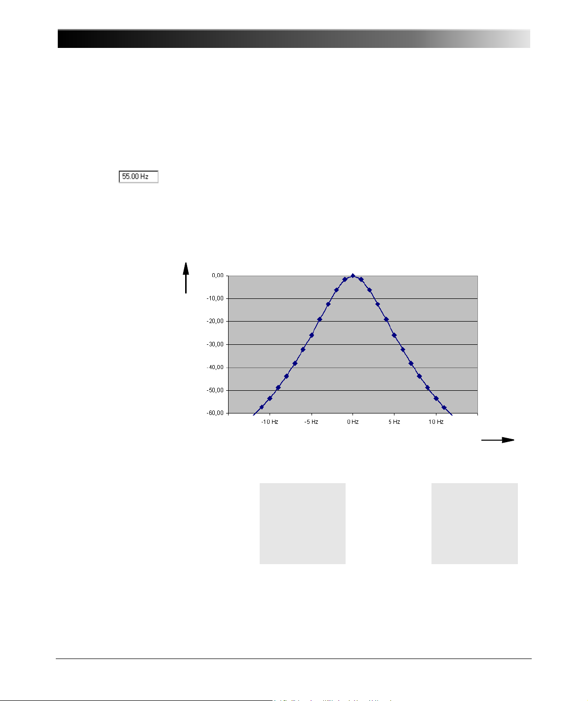
CPC 100 V 1.44
Amplitude in dB
f in Hz
Offset from output frequency
Figure 2:
Characteristics of the
frequency-selective
measurement
The Frequency-Selective Measurement
The frequency-selective measurement is used to filter out interferences as they
usually occur in substations. To do so, the frequency of the CPC 100 output
quantity is set to a value different from the substation’s frequency, for example,
the substation operates with a frequency of 50 Hz, the CPC 100 output
frequency is set to 55 Hz.
The quantity measured back at the CPC 100 input is measured selectively, that
is, only a quantity with the specified frequency is fully taken into consideration
for the measurement. Quantities with different frequencies are filtered out
according to the characteristics shown in Figure 2.
3 - 6
Apart from Quick, the frequency-selective measurement is also available for
other test cards:
CT
•CTRatio
• CTBurden
•CTRatioV
• CTLowPower
In Quick, Sequencer and Ramping the frequency-selective measurement is
selectable, whereas at the other test cards, it is preset and cannot be cleared.
VT
•VTRatio
• VTBurden
• VTElectronics
Transformer
• TRRatio
Others
• Sequencer
• Ramping
Page 89
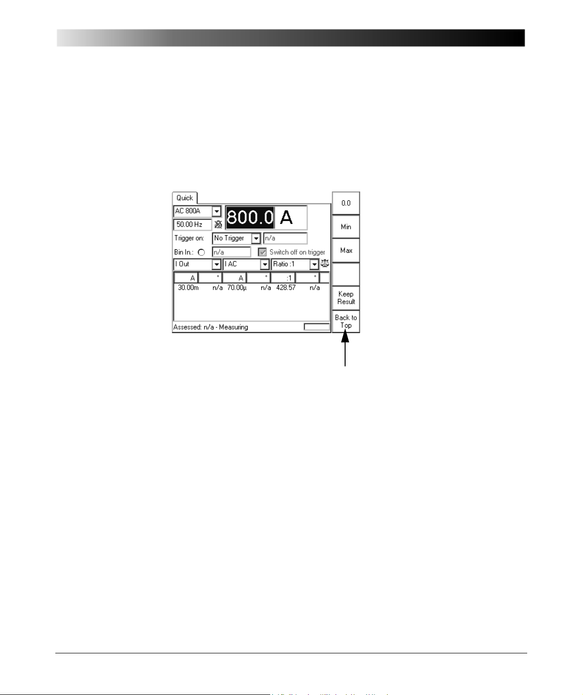
Figure 3:
Note: The designation of the menu keys changes depending on the focus.
Quick test card
Getting Started with Quick
Power Output Settings
The main settings are the range definition and the value for the power output (the
data entry field in Figure 3 that has the focus (
The power output value can be changed instantaneously with the handwheel,
even in the "on" state and while connected to a test object.
Glossary)).
3 - 7
Page 90
CPC 100 V 1.44
Range
Combo box to select between the output ranges
AC 800A, AC 6A, AC 3A, DC 400 A, DC 6 A,
AC 2kV, AC 1 kV, AC 500V, AC 130V and
CB2:1000A, CB2:2000A or
CU20:10A, CU20:20A or
CU1:10A, CU1:20A, CU1:50A, CU1:100A
Either CB2:, CU20: or CU1: output ranges are available
if the respective external booster was selected at the
Options tab Device Setup (see ”Options” on page 2-35)
or on the Settings page of the Quick test card.
Each range has an associated minimum and maximum
value, a fixed precision value as well as a preset number
of decimal characters (refer also to ”Setting Up a Test
Card” on page 2-25).
If Quick operates in the "on" state, the output range
setting is locked and cannot be changed.
While in the "measuring" state with de-activated outputs,
when a range is changed, the output changes
accordingly to a new value within the allowed range
between minimum and maximum.
After having pressed Keep Results, the output range
setting and the measurements settings are locked and
cannot be changed.
Power output value
Current (I) or voltage (V) value, depending on the
specified range (see above).
Any value between minimum and maximum as well as
the explicit value 0.0 is possible, even while in the "on"
state.
The respective minimum and maximum values depend
on the range and, for voltage ranges, also on the
frequency. For frequencies smaller than 50 Hz, and
down to the minimum frequency of 15 Hz, the possible
maximum voltage value decreases linear proportional to
the frequency value (refer to Figure 3, ”Typical maximum
output voltage of 2kV AC output depending on
frequency and power” on page 14-13).
Current ranges do not have such a dependency.
3 - 8
Page 91
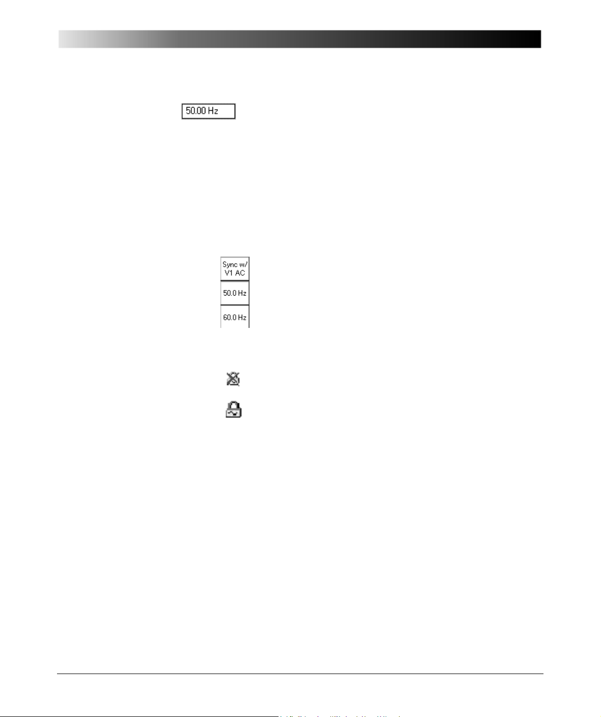
Getting Started with Quick
Frequency / Phase angle
Frequency value in Hz or - if "Sync w/ V1AC" is selected
(see below) - phase angle in degrees. For DC ranges
this data entry field is disabled.
The frequency can be set within a range of
15.00 … 400.00 Hz, even while in the "on" state.
The phase angle is displayed in a range of
-180.0 … +180.0°, and can also be changed at any time.
If this range is exceeded, the phase angle will adapt
itself automatically, that is, change from
-180.0 to +180.0°.
Sync w/ V1AC
Set Sync w/ V1AC by pressing the menu key that
appears when the focus is on the frequency/ phase
angle data entry field.
This synchronizes the CPC 100 output frequency with
the V1 AC input frequency. In this case the phase angle
of the output is displayed rather than the frequency. Set
the phase angle value relative to the phase angle of the
V1 AC input signal (we recommend a minimum input
voltage of 10 V on V1 AC, possible range 48 - 62 Hz).
The icon next to the frequency/ phase angle data entry
field reflects the actual setting.
If "Sync w/ V1AC" is disabled, the frequency returns to
the previously set frequency value and the icon
changes.
If Quick operates in the "on" state, the status of "Sync w/
V1AC" cannot be changed.
Note: Due to the PLL (phase-locked loop) technology,
the synchronization with V1 AC needs about 100 ms.
If for the particular test object the synchronism within the
first 100 ms is relevant, start with a reduced magnitude
of the output signal. Then enter the full magnitude of
your choice, and press Enter.
This procedure assures that the high-level output signal
is synchronized with V1 AC right from the beginning.
3 - 9
Page 92
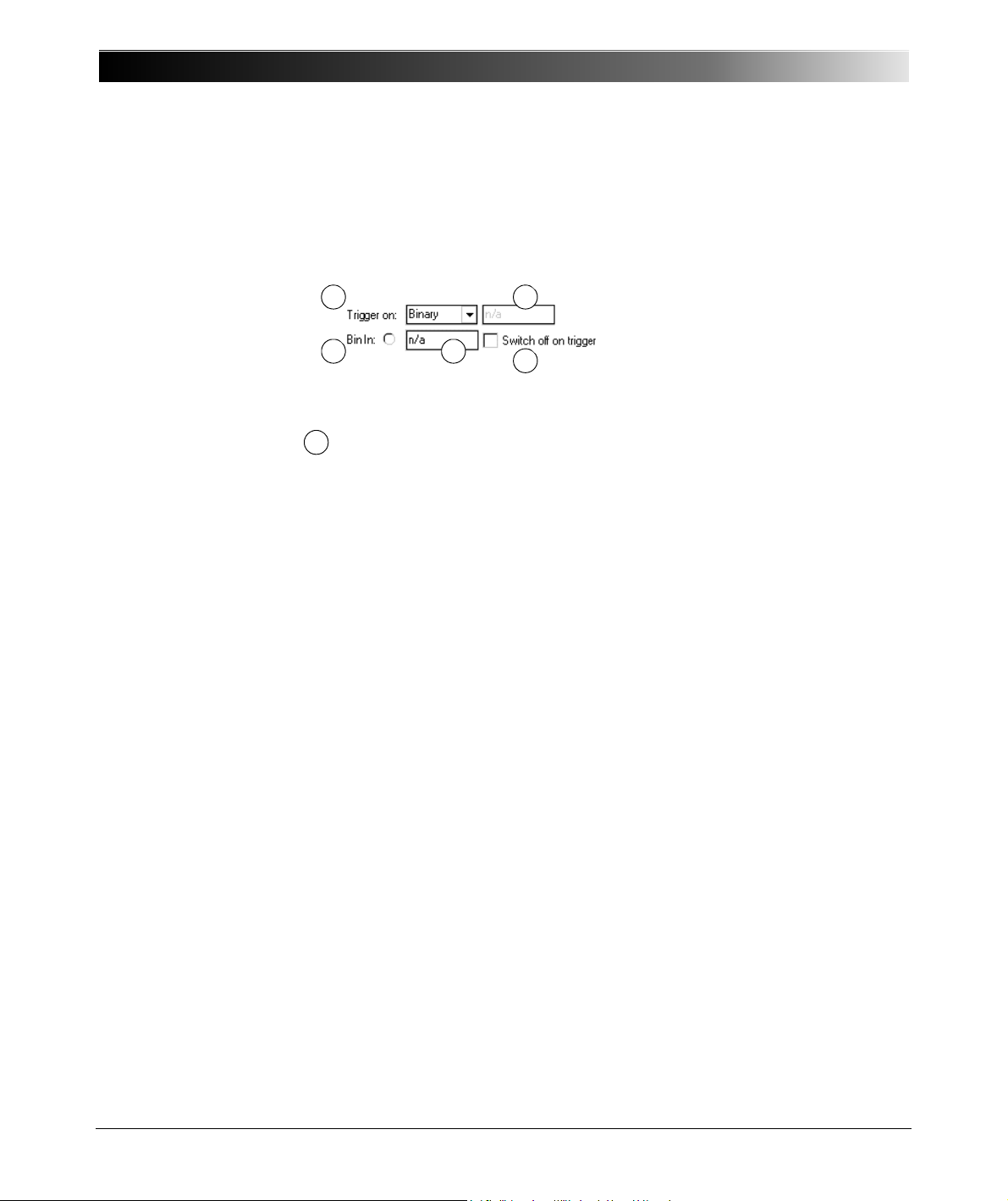
CPC 100 V 1.44
1 2
3
4
5
1
Trigger Settings
A trigger is the occurrence of a selected event, for example, a binary trigger is
the first change of the state at the binary input.
Trigger on:
Selection of trigger event
• no trigger (default)
• binary trigger = CPC 100 input BIN IN is monitored for a trigger event
• trigger = first measurement value (m1) > set threshold value
• trigger = first measurement value (m1) < set threshold value
• trigger = second measurement value (m2) > set threshold value
• trigger = second measurement value (m2) < set threshold value
• overload = the trigger event is an overload condition that occurs at
the selected output.
What is an "Overload" trigger?
3 - 10
At the 800A AC output, an overload trigger is a condition in which
the set current cannot be reached any longer, for example, because
of an opening contact or circuit breaker.
Note: Current values
current circuit opens. Therefore, if you use the trigger condition
"Overload", choose a nominal current value of
Quick differentiates two "Overload" trigger conditions:
1.the occurrence of an overload (as described above)
2.the clearing of an overload condition (clearing is delayed by 100 ms
to debounce).
50 A do not initiate an "Overload" when the
50 A.
Page 93
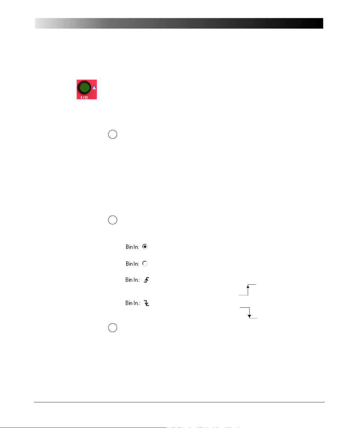
Getting Started with Quick
2
3
4
Note: Trigger conditions with "<" are meaningful in combination with
external signals only, that is, with signals that are not coming from the
CPC 100.
Reason: if the trigger signal comes from the CPC 100, the trigger
condition will always be "true" at the moment the I/O (test start / stop)
push-button is pressed.
After having pressed Keep Results, the trigger event is locked and
cannot be changed.
Data entry field for the threshold value.
Setting a threshold value is not possible ("n/ a", as shown above), if
either
• a binary trigger condition
•no trigger
•overload
was selected.
After having pressed Keep Results, data entry for the threshold value
is disabled, that is, the value cannot be changed.
Bin.In:
Indicates the signal condition at the binary input Bin In. 4 different
characteristics are possible:
Closed: potential-free contact between BinIn+ and BinIn–
closed.
Open: potential-free contact between BinIn + and BinIn –
open.
Come:
trigger signal with rising edge occurred at BinIn.
Go:
trigger signal with falling edge occurred at Bin In
Delay time display
The delay time is the time between the last change of the CPC 100
output value and the occurrence of the trigger event.
3 - 11
Page 94

CPC 100 V 1.44
5
Switch off on trigger
This option is available if the trigger condition is either binary or
overload. Else, "switch off on trigger" is preset and cannot be disabled.
"Switch off on trigger" is also locked and cannot be changed after
having pressed Keep Results.
1. Enabled
When the trigger event occurs, the CPC 100 outputs are
switched off immediately (that is, in real-time).
The measurements are updated to show the values at
the time the trigger event occurred, and are then
"frozen", that is, not updated anymore from that moment
on. Quick turns to the "off" state.
At the field for the power output value setting, the data
entry mode is automatically disabled to prevent this
value from being changed. The focus, however,
remains on that field, enabling instant navigation with
the handwheel.
Pressing the menu key Keep Results saves the
measured values in the measurement table. Quick
returns to the "measuring" state, the measurement
continues in a new line of the measurement table.
2. Disabled
The CPC 100 outputs remain active, that is, in "on"
state, after the trigger event occurred. If the trigger is
binary, the "BinIn" indicator reflects the occurrence of
the trigger event accordingly.
The focus remains in data entry mode on the field for the
power output value setting, allowing an immediate
change of the output value.
The measurements continue after the trigger event.
As soon as the output value is changed, the display of
the most recent delay time is removed.
3 - 12
Page 95

Current Transformer
Current Transformer
Contents of this section
Scope of Current Transformer Tests............................................... page 4-2
CTRatio (and Burden) ..................................................................... page 4-3
Testing Ratio, Polarity (and Burden)
with Injection to Current Input ..................................................... page 4-3
Testing Ratio, Polarity (and Burden) with a Current Clamp ..... page 4-10
CTBurden...................................................................................... page 4-11
CTExcitation (Kneepoint) .............................................................. page 4-15
Winding Resistance ...................................................................... page 4-20
Voltage Withstand Test ................................................................. page 4-25
Polarity Check ............................................................................... page 4-28
CTRatioV (with Voltage)................................................................ page 4-33
CTRogowski (Ratio) ...................................................................... page 4-38
CTLow Power (Ratio).................................................................... page 4-43
TanDelta........................................................................................ page 4-48
Note: With regard to software handling, this section confines to test-relevant
issues, and does not go into detailed procedural descriptions.
It is assumed that you have read and understood the section ”How to Use the
CPC 100 Software” on page 2-17.
4 - 1
Page 96
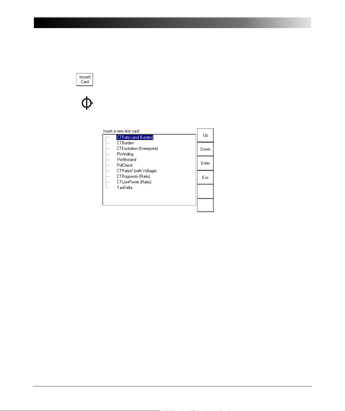
CPC 100 V 1.44
Figure 1:
Inserting CT test cards
Scope of Current Transformer Tests
Go to the Test Card View and press Insert Card.
Use the context-dependent Up/ Down menu keys to the right, or the handwheel,
to browse through the structure. On CT, press Enter.
Alternatively, press the accelerator key to open Insert a new test card.
CT comprises the following test cards:
4 - 2
Highlight the test card of your choice either by navigating with the handwheel or
by using the context-dependent Up/ Down menu keys, and press Enter.
Note: The test cards
• CTRatio (and Burden)
• CTBurden
• CTRatioV (with Voltage)
• CTLowPower (Ratio)
employ the method of frequency-selective measurement, which is used to filter
out interferences as they usually occur in substations.
To learn more about frequency-selective measurement, please refer to ”The
Frequency-Selective Measurement” on page 3-6.
Page 97
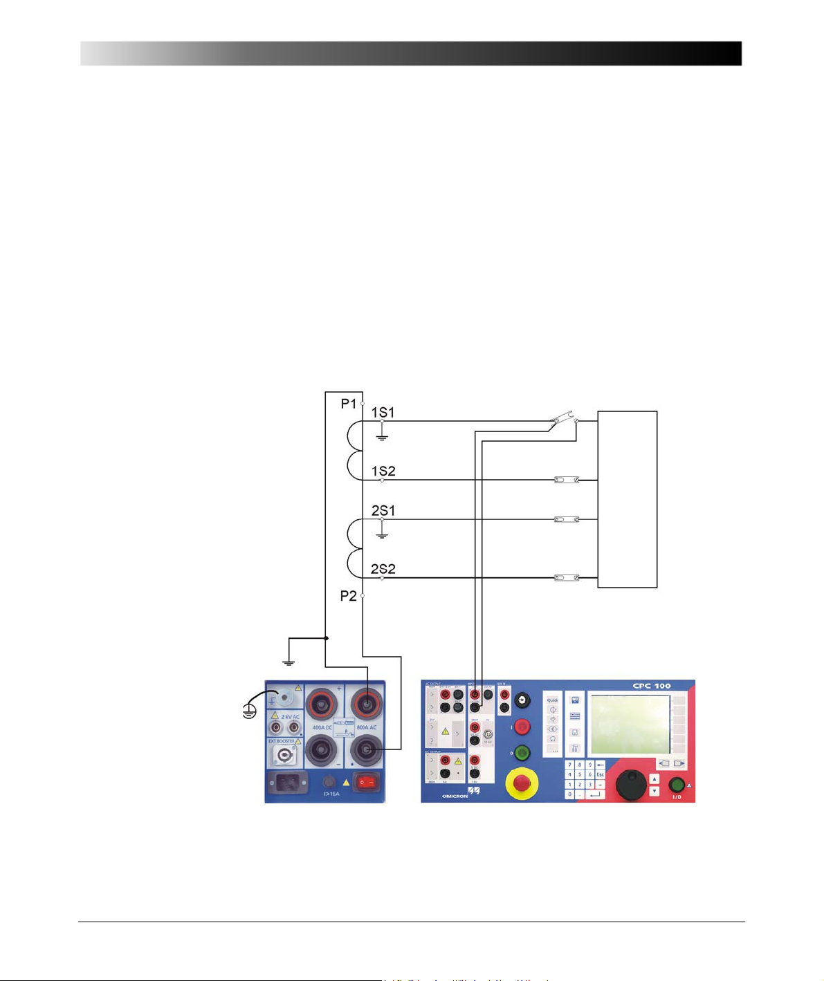
Figure 2:
CT
Burden
Setup of testing ratio,
polarity (and burden)
with injection to current
input
Current Transformer
CTRatio (and Burden)
Testing Ratio, Polarity (and Burden) with Injection to Current Input
Use the CTRatio test card to measure a current transformer’s ratio and burden
with injection on the CT’s primary side with up to 800 A from the 800A ACoutput
or up to 2000 A using the CP CB2 current booster connected to the "EXT.
BOOSTER" output.
It measures amplitude and phase angle of the current (at IAC) and voltage
(at V1 AC) on the transformer’s secondary side, and calculates the actual ratio
and the deviation from the nominal ratio.
4 - 3
Page 98
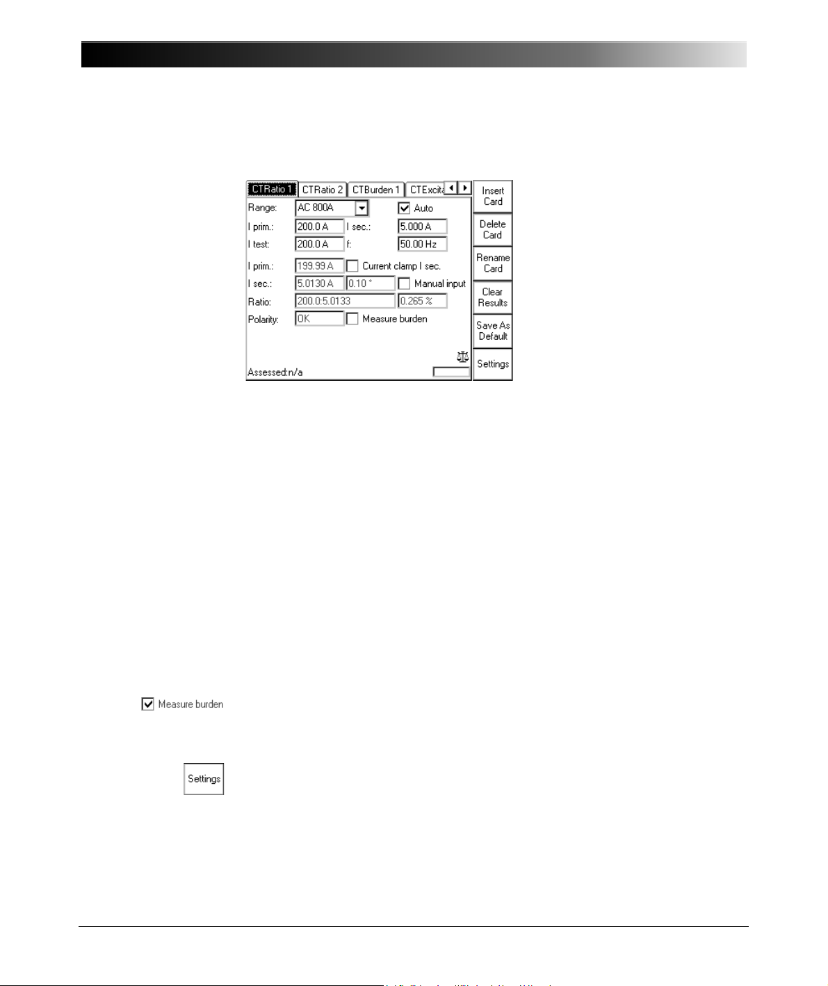
CPC 100 V 1.44
Figure 3:
CTRatio test card with
test results
Test settings
Navigate to the parameter fields, and enter the values according to your test
requirements:
Range: output range
Iprim: nominal primary current
Isec: nominal secondary current
Itest: primary injection current.
f: output frequency
Auto select check box for automatic test (default), clear for manual
test (refer to page 4-7).
Note: If the test involves either an external booster to gain a higher output
current or a current clamp to measure I sec, set these devices at the Options
tab Device Setup before starting the test.
Measure
Burden
The option Measure Burden lets you measure the burden, the
secondary voltage and the cos
(cosinus of angle between
secondary current and secondary voltage).
Pressing the Settings menu key opens the Settings page. The Settings page
allows setting the test cards individually. As a rule, do not use the Settings page
but the Device Setup tab in the Options view (see ”Device Setup” on page 2-
35) to set the test cards. For more information, see ”Settings Page” on page 2-
28.
4 - 4
Page 99

Current Transformer
Three methods to determine I sec
The secondary current Isec can be determined either
1. by leading it directly via the 10A current input IAC (refer to Figure 2 on page
4-3), and let the CPC 100 measure it.
2. by means of a current clamp that is connected, for example, to the V2 AC
low-level AC voltage measuring input (refer to ”Testing Ratio, Polarity (and
Burden) with a Current Clamp” on page 10 of this chapter).
3. by selecting the check box Manual input. This option lets you enter the value
for I sec manually, for example, when I sec was measured with an external
current clamp that is not connected to the CPC 100.
Note: Select Manual input prior to starting the test. If the test card still contains
results, clear them by pressing Clear Results.
When Manual input is selected, there is no phase available. Consequently, the
polarity and cos
cannot be calculated.
Measurements
Iprim: actual current output at the 800 A AC output that is injected into
the CT’s primary side
Isec:
measured secondary current and phase angle
relative to
Iprim
Ratio:
ratio Iprim /Isec., here 200:5.0133
1
and deviation of current ratio in %.
((Kn x Isec - I prim) / Iprim) x 100%
2
((200A / 5A * 5.013 A - 199.99A) / 199.99A) x 100 % = + 0.265%
Polarity: displays the status of the polarity
OK = phaseIsec - phaseIprim = - 45 °< 0° < +45°
NOT OK = all other cases
1. The value 5.0133 is calculated as follows:
Isec act x (Iprim nom / Iprim act); here: 5.013 A x (200A / 199.99A) = 5.0133
2. Kn = rated transformation value, here: 200A / 5A
4 - 5
Page 100
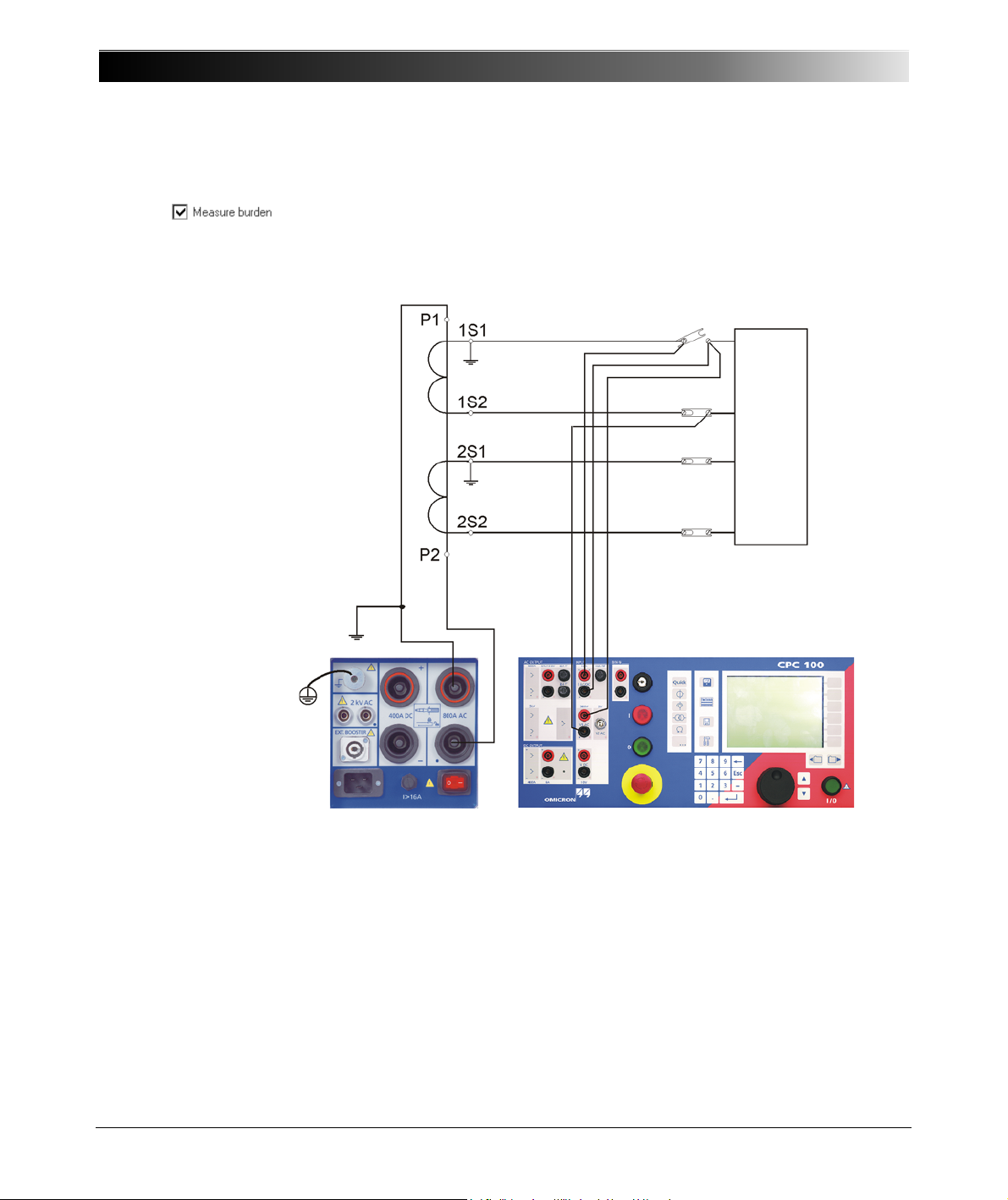
CPC 100 V 1.44
CT
Burden
Figure 4:
Setup for testing ratio,
polarity and burden with
injection to current input
The "Measure burden" option
Select the check box Measure Burden to measure the burden in VA.
Note: This option is only useful as long as the injected current I test is about of
the magnitude of the nominal current I prim.
4 - 6
Note: For CTs that have a hole rather than a primary busbar just loop the highcurrent cable through the hole and connect the high-current clamps together.
 Loading...