

Page 1

27
Reference Manual
CMGPS
Synchronization Unit
Page 2

GPS Synchronization Unit CMGPS
Article number VESD0200 - Manual version: CMGPS.AE.6 - Year 2011
© OMICRON electronics. All rights reserved.
This manual is a publication of OMICRON electronics GmbH.
All rights including translation reserved. Reproduction of any kind, e.g., photocopying, microfilming,
optical character recognition and/or storage in electronic data processing systems, requires the explicit
consent of OMICRON electronics. Reprinting, wholly or in part, is not permitted.
The product information, specifications, and technical data embodied in this manual represent the
technical status at the time of writing and are subject to change without prior notice.
We have done our best to ensure that the information given in this manual is useful, accurate and
entirely reliable. However, OMICRON electronics does not assume responsibility for any inaccuracies
which may be present.
The user is responsible for every application tha t ma ke s us e of an OM ICRO N pr od u ct.
OMICRON electronics translates this manual from the source language English into a number of other
languages. Any translation of this manual is done for local requirements, and in the eve nt of a dispute
between the English and a non-English version, the English version of this manual shall govern.
2
Page 3

Contents
Contents
Preface . . . . . . . . . . . . . . . . . . . . . . . . . . . . . . . . . . . . . . . . . . . . . . . . . . . . . . .5
1 Designated Use . . . . . . . . . . . . . . . . . . . . . . . . . . . . . . . . . . . . . . . . . . . . . . . .9
2 Introduction . . . . . . . . . . . . . . . . . . . . . . . . . . . . . . . . . . . . . . . . . . . . . . . . . .11
2.1 What is GPS? . . . . . . . . . . . . . . . . . . . . . . . . . . . . . . . . . . . . . . . . . . . . .11
2.2 Purpose of the CMGPS. . . . . . . . . . . . . . . . . . . . . . . . . . . . . . . . . . . . . .12
3 Construction and Functioning . . . . . . . . . . . . . . . . . . . . . . . . . . . . . . . . . . .13
3.1 Components . . . . . . . . . . . . . . . . . . . . . . . . . . . . . . . . . . . . . . . . . . . . . .13
3.2 LED Status Display . . . . . . . . . . . . . . . . . . . . . . . . . . . . . . . . . . . . . . . . .17
3.3 Connections and Interfaces. . . . . . . . . . . . . . . . . . . . . . . . . . . . . . . . . . .19
3.3.1 DC in Power Supply . . . . . . . . . . . . . . . . . . . . . . . . . . . . . . . . . .19
3.3.2 Antenna Input . . . . . . . . . . . . . . . . . . . . . . . . . . . . . . . . . . . . . . .20
3.3.3 ext. Interf. . . . . . . . . . . . . . . . . . . . . . . . . . . . . . . . . . . . . . . . . . .21
3.3.4 Pulse out 2 Interface. . . . . . . . . . . . . . . . . . . . . . . . . . . . . . . . . .22
3.3.5 Block Diagram of the CMGPS . . . . . . . . . . . . . . . . . . . . . . . . . .23
4 Operating the CMGPS . . . . . . . . . . . . . . . . . . . . . . . . . . . . . . . . . . . . . . . . . .25
4.1 Connecting the CMGPS to a CMC Test Set . . . . . . . . . . . . . . . . . . . . . .26
4.2 Connecting the CMGPS to a CMC 56. . . . . . . . . . . . . . . . . . . . . . . . . . .27
5 Synchronizing Two or More CMC Test Sets . . . . . . . . . . . . . . . . . . . . . . . .29
5.1 Standard Accuracy Mode . . . . . . . . . . . . . . . . . . . . . . . . . . . . . . . . . . . .30
5.2 Enhanced Accuracy Mode. . . . . . . . . . . . . . . . . . . . . . . . . . . . . . . . . . . .31
5.3 Using CMGPS in Conjunction with CMIRIG-B . . . . . . . . . . . . . . . . . . . .32
3
Page 4

GPS Synchronization Unit CMGPS
6 Technical Data . . . . . . . . . . . . . . . . . . . . . . . . . . . . . . . . . . . . . . . . . . . . . . . .35
6.1 CMGPS in General . . . . . . . . . . . . . . . . . . . . . . . . . . . . . . . . . . . . . . . . .35
6.2 GPS Receiver . . . . . . . . . . . . . . . . . . . . . . . . . . . . . . . . . . . . . . . . . . . . .35
6.3 Power Supply . . . . . . . . . . . . . . . . . . . . . . . . . . . . . . . . . . . . . . . . . . . . .36
6.4 Antenna. . . . . . . . . . . . . . . . . . . . . . . . . . . . . . . . . . . . . . . . . . . . . . . . . .36
6.5 ext. Interf.. . . . . . . . . . . . . . . . . . . . . . . . . . . . . . . . . . . . . . . . . . . . . . . . .37
6.6 Pulse Out 2 Interface. . . . . . . . . . . . . . . . . . . . . . . . . . . . . . . . . . . . . . . .38
6.7 CE Conformity, Electromagnetic Compatibility . . . . . . . . . . . . . . . . . . . .39
6.8 Insulation Coordination . . . . . . . . . . . . . . . . . . . . . . . . . . . . . . . . . . . . . .39
6.9 Safety Standards, Certificates. . . . . . . . . . . . . . . . . . . . . . . . . . . . . . . . .40
7 Faults, Possible Causes, Remedies. . . . . . . . . . . . . . . . . . . . . . . . . . . . . . .41
8 Appendix. . . . . . . . . . . . . . . . . . . . . . . . . . . . . . . . . . . . . . . . . . . . . . . . . . . . .43
8.1 Ordering Information . . . . . . . . . . . . . . . . . . . . . . . . . . . . . . . . . . . . . . . .43
8.2 Cleaning . . . . . . . . . . . . . . . . . . . . . . . . . . . . . . . . . . . . . . . . . . . . . . . . .44
Contact Information / Technical Support . . . . . . . . . . . . . . . . . . . . . . . . . .45
Index . . . . . . . . . . . . . . . . . . . . . . . . . . . . . . . . . . . . . . . . . . . . . . . . . . . . . . . .47
4
Page 5

Preface
Preface
The purpose of this reference manual is to familiarize users with the CMGPS
synchronization unit and to show how to properly use it in various application
areas.
The reference manual contains import ant tips on how to use the CMGPS
synchronization unit safely, properly, and efficiently. Its purpose is to help you
avoid danger, repair costs, and down time as well as to help maintain the
reliability and life of the CMGPS synchronization unit.
This reference manual is to be supplemented by existing national safety
standards for accident prevention and environmental protection.
The reference manual should always be available at the site wher e the CMGPS
synchronization unit is used. It should be read by all personnel operating the
synchronization unit.
Note: The OMICRON Test Universe sof tware also installs a PDF version of this
reference manual. It can directly be opened by a mou se-click from the help
topic "User Manuals". The Test Universe Help can be launched by clicking Help
on the Start Page.
In addition to the reference manual and the applicable safety regulations in the
country and at the site of operation, the usual technical proced ures for safe and
competent work should be heeded.
Note: This reference manual describes the CMGPS synchronization unit
hardware - that is, the physical device. In order to get familiar with the software
for controlling and configuring the CMGPS synchronization unit, please refer to
the software manuals and/or the OMICRON Test Universe Help.
5
Page 6
GPS Synchronization Unit CMGPS
Safety Requirements
Before operating the CMGPS, carefully read the following safety
instructions.
Only operate the CMGPS after you have read this manual and fully
understood the instructions herein.
The CMGPS may only be operated by trained personnel. Any
maloperation can result in damage to property or persons.
Principles, Designated Use
•The CMGPS should only be used when in a technically sound condition. Its
use should be in accordance with the safety regulations for the specific job
site and application. Always be aware of the dangers of the high volt ages and
currents associated with this equipment. Pay attention to the information
provided in the reference manual and the software documentation.
•The CMGPS is exclusively intended for the application areas specified in
section 1, "Designated Use" on page 9. The manufacturer/distributors are not
liable for damage resulting from unintended usage. The user alone assumes
all responsibility and risk.
• The instructions provided in this reference manual and the associated
software manuals are considered part of the rules governing proper usage.
• Do not open the CMGPS or remove any of its housing components.
Orderly Practices and Procedures
• The reference manual (or its "electronic PDF pendant", which is installed to
your computer with the OMICRON Test Universe software) should always
be available on site where the CMGPS is used.
Note: The OMICRON Test Universe software also inst alls a PDF version of
this reference manual. It can directly be opened by a mouse-click from the
help topic "User Manuals". The Test Universe Help can be launched by
clicking Help on the Start Page.
• Personnel assigned to using the CMGPS must have read this reference
manual and fully understood the instructions herein.
• Do not carry out any modifications, extensions or adaptations at the
CMGPS.
6
Page 7

Operator Qualifications
• Testing with the CMGPS should only be carried out by authorized and
qualified personnel.
• Personnel receiving training, instruction, direction, or education on the
CMGPS should remain under the constant supervision of an experienced
operator while working with the equipment.
Safe Operation Procedures
•The CMGPS is to be set into operation in accordance with the information
provided in section 4 ”Operating the CMGPS”.
•The CMGPS must not be opened! If the device is opened, no guarantee
claims can be made.
•Do not position the antenna of the CMGPS in an exposed location above
the lightning rod or in other locations endangered by lightning. Make
sure that the position of the lightning rod is higher than that of the antenna
in any case.
When installing the CMGPS, observe the general rules for lightning
protection complying with the industrial standard.
In addition to that, do not position the antenna within a control cabinet in
the vicinity of flashover-endangered spots.
•The CMGPS must not be used in connection with devices with an
operating voltage that exceeds 250 V r.m.s. (for further details refer to
section 6.8 ”Insulation Coordination”).
• The electric equipment of the CMGPS is to be regularly checked. Any
fault such as loose connections or defective cables is to be immediately
repaired.
Preface
• If work has to be carried out on components connected to the mains
supply, a second person is required who presses, in case of emergency,
the emergency stop and/or the main push button with overvoltage
release.
7
Page 8

GPS Synchronization Unit CMGPS
8
Page 9

1 Designated Use
The CMGPS is designed to either
• control one OMICRON CMC test set at a predetermined point in time
(triggering the starting point of a test process) or
• to synchronize the starting point of a test pr oc ess of two or more
OMICRON CMC test sets.
by means of the GPS signal with world-wide reception.
The test set is controlled:
1
•via the ext. Interf. input
or
• via a binary input on the front of the CMC test set.
Using the CMGPS for other purposes than those described above is not
considered the designated use.
at the rear of the CMC test set
Designated Use
The CMGPS's specifica tions have been determined in the course of a project to
develop a mobile synchronization unit for CMC test sets. The CMGPS may not
be installed stationary.
Any other use of the CMGPS is only permitted after OMICRON electronics has
expressly agreed to it.
Observance of the operating instructions and compliance with the precautions
outlined therein is part of the defined use.
1. Refer also to section 3.3.3 ”ext. Interf.”.
9
Page 10

GPS Synchronization Unit CMGPS
10
Page 11
2.1 What is GPS?
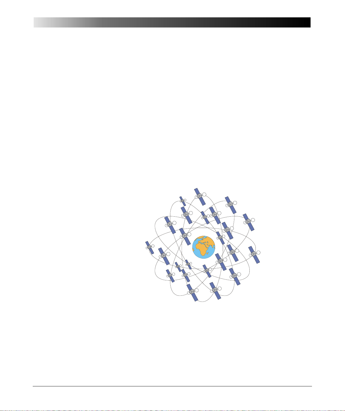
Figure 2-1:
The NAVSTAR
satellites on their orbits
Introduction
2 Introduction
The Global Positioning System (GPS) is one of two satellite navigation systems
covering the whole earth. It was developed in 1978 by the US Department of
Defence to replace TRANSIT, the first US satellite navigation system, and was
initially designed to develop the defence ability of the USA.
The second system currently being used is the GLObal NAvigation Satellite
System (GLONASS), operated by Russia. The system was completed in 1995.
Technical Principles
GPS navigation is based on the principle of determining the distance between a
certain location on the earth to the NAVSTAR satellites revolving around the
earth on six different orbits twice a day. Their orientation in relation to the
equator is approx. 55 °.
The satellites are continuously sending encoded position and time information
in a frequency range of approx. 1500 MHz.
Special GPS receivers (passive receivers) receive these signals and dete rmine
their exact position in the system of earth co-ordinates by means of the signal
code as well as measurement of the time span between receiving the signals.
At the same time, the GPS receiver’s clock is synchronized to the atomic clocks
aboard the GPS satellites.
11
Page 12
GPS Synchronization Unit CMGPS
Antenna
ext. Interf.
ext. Interf.
CMC 356
Pulse out 2
Power supply unit
2.2 Purpose of the CMGPS
Figure 2-2:
CMGPS connected to
CMC 356 test set
CMGPS is a system extension which allows for controlling (triggering) a CMC
test set at a precisely defined moment via the GPS
1
satellite signal with world-
wide reception (see also section ”Technical Principles”).
Based on this innovative test method by using two or mo re CMGPS extension
units, two or more CMC test sets can be started simultaneously with a
2
synchronization error of the CMGPS output of < 1 µs
. There may be any
distance between these test sets to be synchronized (see also
section 5 ”Synchronizing Two or More CMC Test Sets”).
By utilizing the GPS signal it is thus possible to ensure identical trigger time of
test processes of several independently operating test units, regardless of the
distance between them.
12
1. Global Positioning System
2. Depends on the accuracy set by means of the software (please also refer to chapter
5.1 ”Standard Accuracy Mode”).
Page 13

3.1 Components
Article number VEHZ3000
Article number VEHZ1103
Figure 3-1:
Synchronization unit
CMGPS
Construction and Functioning
3 Construction and Functioning
The CMGPS consists of the following components:
Figure 3-2:
Power supply unit
100 - 240 V
incl. plug-in adapter for
country-specific wall
outlets
/18 VDC
AC
13
Page 14
GPS Synchronization Unit CMGPS
Article number VEHK0003
Article number VEHZ3001
Figure 3-3:
Connection cable
CMGPS ext. Interf.
CMC test set
⇔
Figure 3-4:
Active antenna
14
Page 15
Figure 3-5:
Article number VEHK3002
Antenna
CMGPS
2 extension cables + SMA adapter (see also figure 3-7).
Article number VEHZ3003
15 m (50 ft) RG58
coaxial cable with SMA
connector (extension
cable for antenna)
Construction and Functioning
For cases that may require an extension of the antenna cabl e, an optional set of
2 × 20 m (2 x 60 ft) cables is available from OMICRON.
Figure 3-6:
CMGPS connected to
antenna via 2 × 20 m
(2 x 60 ft) extension
cables.
Note: when connecting
VEHZ3003, VEHK3002
shown in figure 3-5
cannot be used
anymore.
15
Page 16

GPS Synchronization Unit CMGPS
Connect to antenna Connect to CMGPS
Extension cables
Figure 3-7:
SMA adapter to connect
the extension cables to
CMGPS and antenna
• Protecting cap for antenna input (no illustration)
• Carrying bag for CMGPS (no illustration)
• User manual (no illustration)
16
Page 17
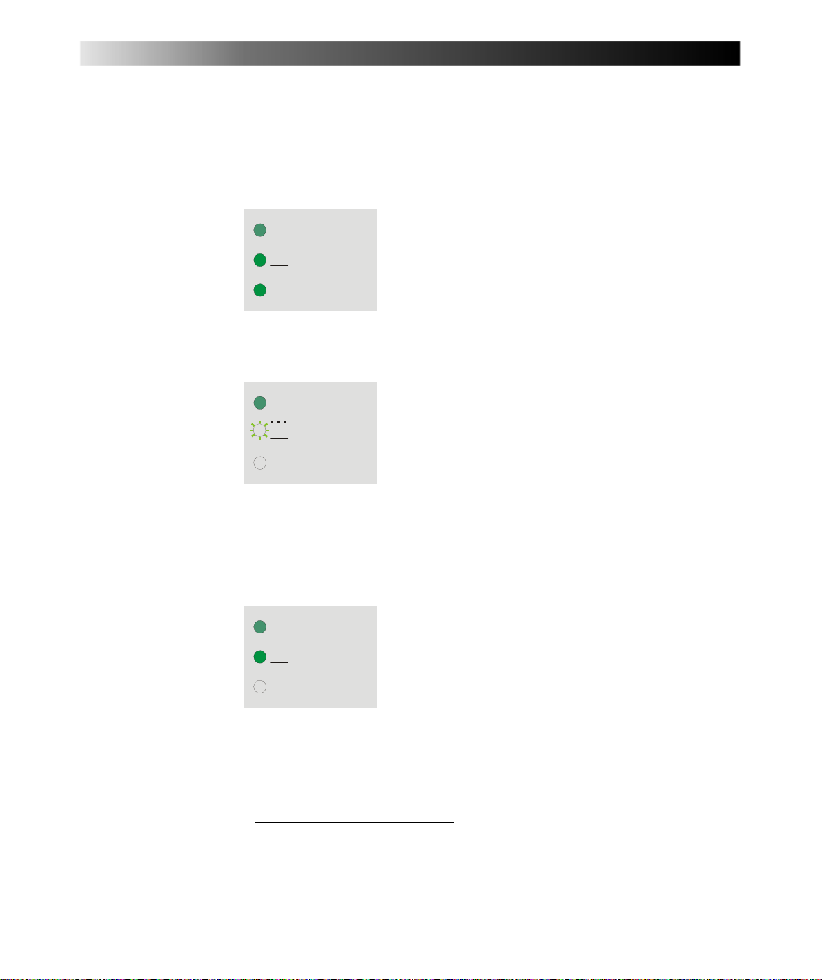
3.2 LED Status Display
On
Pulse
Searching
Locked
All 3 LEDs are lit for about 30 seconds; the GPS
receiver is initialized.
On
Pulse
Searching
Locked
LED "ON" is lit.
LED "Searching/Locked" flashes. The receiver does
not yet receive enough strong satellite signals in
order to put out the synchronization pulse.
On
Pulse
Searching
Locked
LED "ON" is lit.
LED "Searching/Locked" is lit. The receiver acquires
the necessary number of satellite signals of sufficient
strength and can therefore put out the
synchronization pulse with the unit accuracy.
1. The power supply is applied to the CMGPS
2. After the initialization of the CMGPS
Construction and Functioning
Typically, after a time period of max. 5 minutes this status is succeeded by the
condition "CMGPS ready for operation" (refer to the following item)
should not be the case, refer to section 7 ”Faults, Possible Causes, Remedies”.
3. CMGPS is ready for operation
1. This time may increase to up to 20 minutes in cases where the CMGPS was either relocated by
several hundred kilometers since the last time it was in use or out of operation for more than
6months.
1
. If this
17
Page 18
GPS Synchronization Unit CMGPS
On
Pulse
Searching
Locked
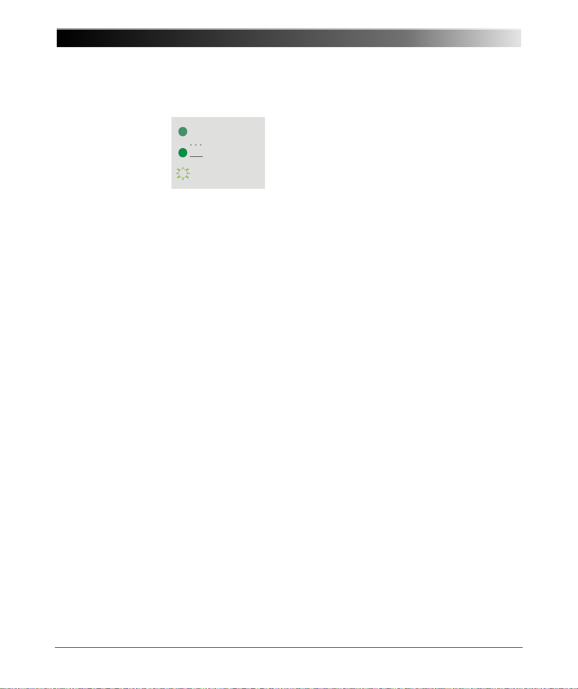
LED "ON" is lit.
LED "Searching/Locked" is lit.
LED "Pulse" is lit for approx. 500 ms during the
output of the synchronization pulse at the outputs
Pulse out 1 and/or Pulse out 2.
Synchronization pulse
Other LED conditions as those described above indica te faults and are outlined
in section 7 ”Faults, Possible Causes, Remedies” on page 41.
18
Page 19

3.3.1 DC in Power Supply
Figure 3-8:
Power supply input
DC in
3.3 Connections and Interfaces
Power supply is applied to the CMGPS by means of a power supply unit
100-240 V
country-specific wall outlets (see figure 3-2 on page 13).
The connector of this power supply unit is reverse polarity protected.
/18 VDC, which is equipped with an adapter for the various
AC
Construction and Functioning
Most of the up-to-date CMC test sets (e.g., CMC 256, CMC 256plus, CMC 353,
CMC 356 or CMC 850) provide power supply to the CMGPS via the connection
cable to the ext. Interf.. Therefore, in conjunction with one of these test sets, the
power supply unit is not needed.
In conjunction with the CMIRIG-B interface unit, use the above mentioned power
supply unit to power the CMGPS.
Note that using such a separate power supply unit keeps the CMGPS in "locked"
mode when the CMC test set is switched off.
19
Page 20

GPS Synchronization Unit CMGPS
Antenna input
3.3.2 Antenna Input
CMGPS uses an active antenna (see figure 3-4 on page 14).
Figure 3-9:
Antenna input of the
CMGPS
The antenna is connected to the antenna input of the CMGPS (SMA socket) by
means of the RG58 coaxial extension cable (see figure 3-5 on page 15).
This extension cable also serves as power supply cable for the antenna of the
CMGPS.
Note: The coaxial extension cable supplied with CMGPS has a length of 15 m
(45 ft.) If that is not sufficient, there is an optional extension set of 2 × 20 m
(2 × 60 ft.) with SMA adapters available for a total extension of 40 m (120 ft.).
Refer to figure 3-6 on page 15 for a view. For ordering information please refe r
to table 8-1 on page 43.
When applying the optional 2 × 20 m (2 × 60 ft.) extension set, the original 15 m
(45 ft.) extension cable cannot be used anymore.
20
Page 21
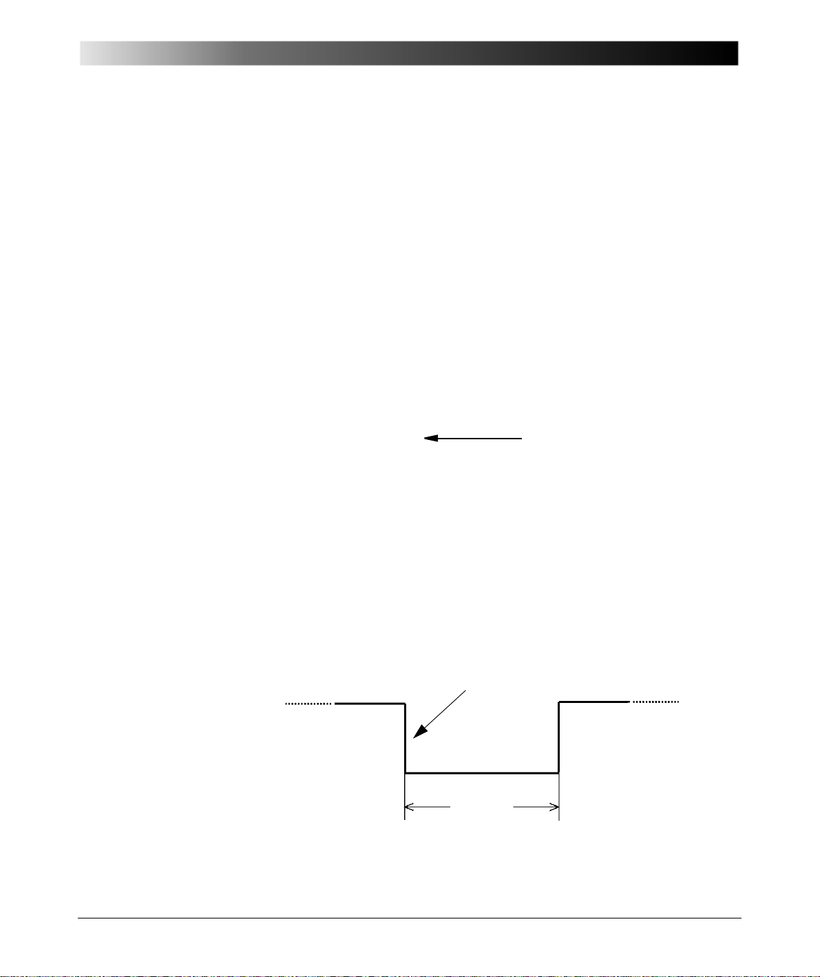
3.3.3 ext. Interf.
Communication interface to
connect CMGPS to the CMC
test set’s ext. Interf.
200 ms
The falling edge of this signal represents the synchronization point of time.
Figure 3-10: Communication interface ext. Interf.
Construction and Functioning
The ext. Interf. (Pulse out 1) is the communication interface between the
CMGPS and the CMC test set.
At this interface, the CMGPS is connected to the CMC test set by means of the
supplied connection cable (see figure 3-3 on page 14).
This interface serves to
• configure the CMGPS via software (e.g., the synchronization time)
• send the "Pulse out 1" synchronization pulse to the CMC test set.
Standardized factory setting of the synchronization pulse is 200 ms output once
per minute.
Note: This output is only to be used together with an OMICRON CMC test set.
Do not use this output for other devices or other applications.
21
Page 22

GPS Synchronization Unit CMGPS
3.3.4 Pulse out 2 Interface
The Pulse out 2 interface is represented by two safety banana sockets.
Figure 3-11:
The Pulse out 2
interface
Via these banana sockets, the synchronization pulse of the CMGPS can be
picked up potential-free by means of an internal opto-electronic coupler (see
also section 6.6 ”Pulse Out 2 Interface” on page 38).
It is put out following the standardized factory setting simultaneously to the
synchronization pulse at the ext. Interf. connector.
Standardized factory setting of the synchronization pulse is 200 ms output once
per minute.
This interface has been especially designed for the synchronization of a CMC
test set without an integrated ext. Interf. connector.
In order to be able to trigger these CMC test sets by means of the GPS signal,
the CMGPS synchronization signal from the Pulse out 2 interface may be
connected to one of the CMC's binary inputs (see also documenta tion of the test
set and/or software).
By means of the Pulse out 2 interface, the CMGPS can also be utilized as
"standalone" synchronization unit without being connected to a CMC test set.
At present, the Test Universe software supports the configuration of a pulse
output only. Therefore, the Pulse out 2 is synchronous to Pulse out 1.
22
Page 23
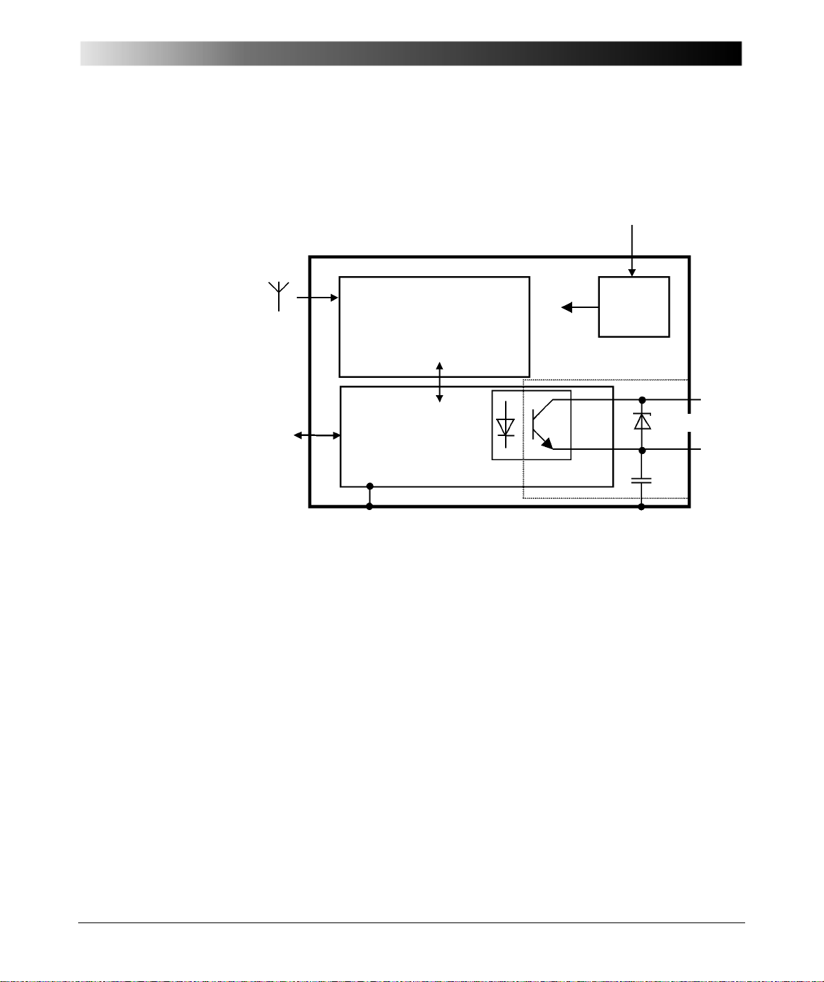
Figure 3-12:
18 VDCfrom
power supply unit
ext. Interf.
Pulse
out 1
DC input
PWR
DC/DC
Pulse out 2
(VDE884)
Housing (metal)Gnd
GPS receiver
Interface modul
(pulse preparation)
Antenna
input
+5V
Y1
Block diagram of the CMGPS
Construction and Functioning
3.3.5 Block Diagram of the CMGPS
23
Page 24

GPS Synchronization Unit CMGPS
24
Page 25

Operating the CMGPS
4 Operating the CMGPS
Please check for the availability of all components prior to operating CMGPS.
For a detailed list of the components please refer to the packaging list.
Standard scope of supply comprises:
• CMGPS synchronization unit
• antenna
• antenna extension cable
• connection cable CMGPS
• power supply unit 100 - 240 V
• CMGPS user manual.
The instructions for operating the CMGPS are based on the precondition that the
CMC test set has been operated in accordance with its manual and is ready for
use.
Operating the CMGPS is as follows:
• Connect the extension cable of the antenna to the CMGPS.
• Connect the antenna to the extension cable. Place the antenna at a
suitable position that provides sufficient open sky.
Do not position the antenna of the CMGPS in an exposed position above the
lightning rod or at another location endangered by lightning.
In addition, do not position the antenna within a control cabinet in the vicinity of
flashover-endangere d spo ts .
⇔ CMC
/18 V
AC
DC
25
Page 26
GPS Synchronization Unit CMGPS
1. Connect the ext. Interf. of the CMGPS to
the ext. Interf. input at the re ar of the CMC
test set by means of the supplied
connection cable VEHK0003 (shown in
figure 3-3).
2. Plug in the DC adapter of
the 100-240 V
AC
/18 V
DC
power supply unit to the
DC in power supply input of
the CMGPS.
3. Connect the power supply
unit to a wall outlet.
Note: The power supply
unit is not needed with upto-date test sets such as
CMC 256, CMC 256plus,
CMC 353, CMC 356 and
CMC 850. In conjunction
with the CMIRIG-B interface
unit, use the above
mentioned power supply
unit to power the CMGPS.
On
Pulse
Searching
Locked
LED "ON" is lit.
LED "Searching/Locked" is lit.
4.1 Connecting the CMGPS to a CMC Test Set
Figure 4-1:
CMGPS communication
interface ext. Interf.
Figure 4-2:
Power supply unit
100 - 240 VAC/18 VDC
incl. plug-in adapter for
country-specific wall
outlets
26
1. Section 3.2 ”LED Status Display” on page 17 describes the state of the LED
signalization during the activation and initialization of the CMGPS.
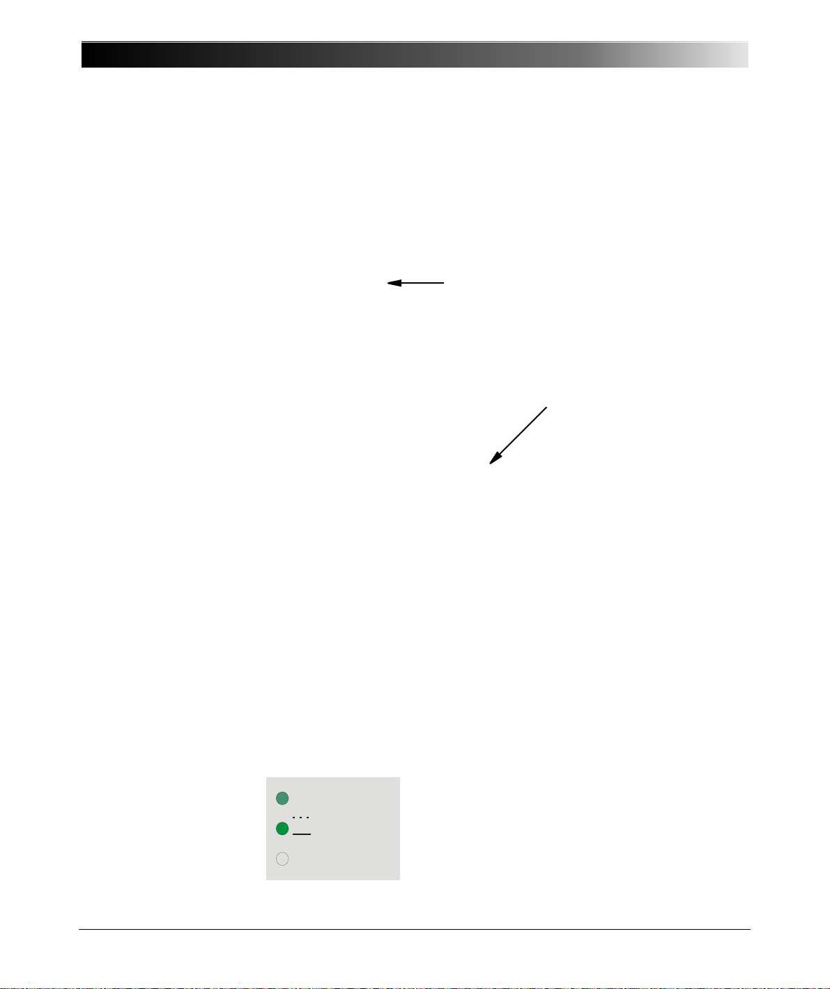
The following explanations are based on successful initialization and on the
fact that the CMGPS locked itself to the GPS signal.
The state of the LEDs of the CMGPS should then be as follows:
Page 27

Figure 4-3:
Use two suitable cables with banana plugs and
connect the Pulse out 2 interface ("+" and "-")
to a binary input of the CMC 56.
Make sure the polarity of the connection
cables is correct.
The Pulse out 2
interface
Operating the CMGPS
2. The synchronization pulse of 200 ms is sent in regular intervals of 1 minute
(synchronization on falling edge). Every synchronization pulse sent is
indicated by the "Pulse" LED that lights up for 500 ms.
3. This synchronization pulse can now be used as trigge r pulse for starting one
or several test processes. The required settings are determined by software
parameters (see respective software documentation and/or on-line help).
Typically, the CMGPS is ready for operation max. 10 minutes after the powe r
supply has been applied to it. If this should not be the case, refer to
section 7 ”Faults, Possible Causes, Remedies” on page 41.
4.2 Connecting the CMGPS to a CMC 56
Earlier versions of the CMC 56 test set do not have an ext. Interf. connector at
their rear side. If you have such a test set, connect the CMGPS to a bina ry input
instead.
27
Page 28

GPS Synchronization Unit CMGPS
28
Page 29

5 Synchronizing Two or More CMC
CMGPS CMGPS
Signal Signal
Relay Relay
CMC 356 CMC 3563V, 3I, Trip 3V, 3I, Trip
Antenna Antenna
Test Universe
software
Test Universe
software
Figure 5-1:
Example: Testing a
power transmission
line's protection system
with two
GPS-synchronized
CMC test sets
Synchronizing Two or More CMC Test Sets
Test Sets
Figure 5-1 shows a typical field application of the CMGPS synchronization unit:
Power transmission lines are usually protected by means of distance or
differential relays. Line differential relays require a signal link for comparing
currents' amplitudes or phases at both ends of the line. Distance relays are qu ite
often equipped with signal links in order to enable instantaneous tripping at
100 % of the protected line segment.
Here, two CMGPS synchronization units trigger two CMC test sets to start a test
at the exact same point of time. Since the GPS signal is available worldwide, the
physical distance between these test sets is thereby of no relevance ("end to
end" testing).
The synchronization accuracy depends on the settings made at the Time
Trigger Configuration window of the Test Universe software. Test Universe
differentiates between standard and enhanced accuracy. See th e following
chapters.
29
Page 30
GPS Syncronization Unit CMGPS
GPS output pulse
Binary input
sampling of
the CMC at
substation A
Binary input
sampling of
the CMC at
substation B
100 μs
The CMC at substation A
picks up the GPS pulse
The CMC at substation B
picks up the GPS pulse
Time difference
< 100 μs
Falling slope is within
± 1 μs to
programmed time at both sides
5.1 Standard Accuracy Mode
If such a protection scheme is to be reliably tested, it has to be tested as a
complete system, i.e. the relays on both sides of the transmission line, the
signal link and the functional interaction of all the components ha ve to be tested.
Using two CMC test sets — one at the beginning of the transmission line and
one at the end — performs this function. The two devices are synchronized by
means of a CMGPS.
After the CMGPS synchronization units have received signals from a sufficient
number of satellites, they can determine the exact time.
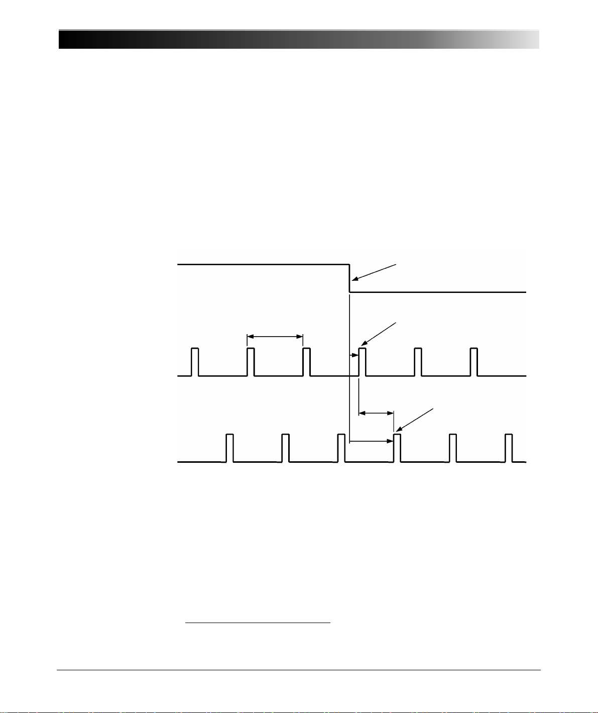
Figure 5-2:
Timing Relationship
when using CMGPS
and multiple CMC test
sets
30
The GPS output pulse is issued at the same time (+/- 1 µs1) from the GPS
receivers in both substations. The test sets have a 100 µs sampling rate for
reading the status of the binary inputs, which also applies to the external input
for the GPS output signal. The timing of the binary input sampling is not
synchronized between the two test sets. Due to this, a time dif fe re nc e of up to
100 µs can appear between the pickup of the GPS pulse by the two test sets.
This can result in an equivalent phase difference of a maximum of 1.8 ° at 50 Hz
or a maximum of 2.16 ° at 60 Hz.
1. Depending on set accuracy (configuration in software)
Page 31
5.2 Enhanced Accuracy Mode
GPS output pulse
Analog output
Waiting condition - no output
Falling slope is within
± 1 μs to
programmed time at both sides
Time difference
< 5 μs (typ.
≈ 1 μs)
Substation A
Substation B
first zero crossing
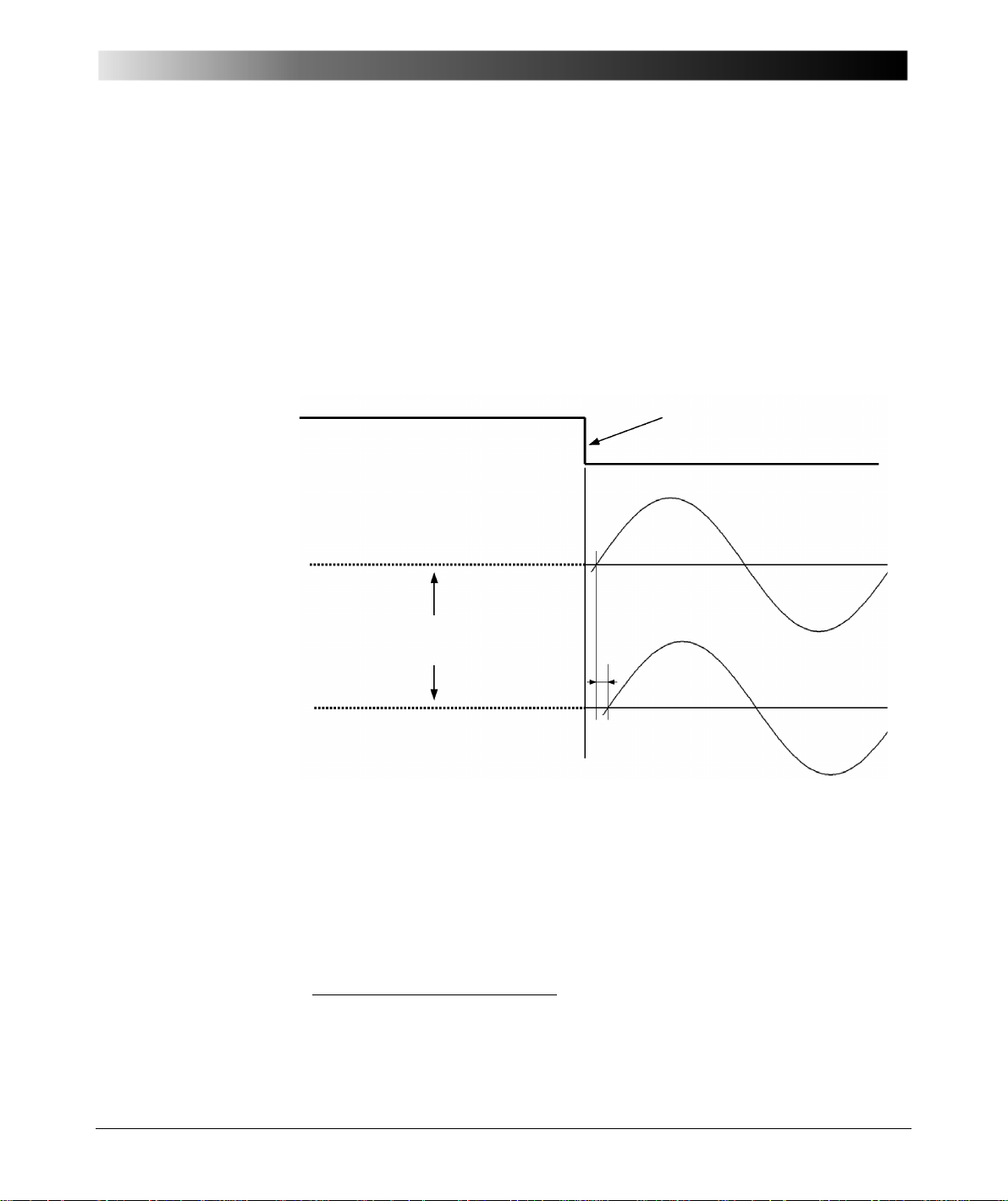
Figure 5-3:
Behaviour of the
Enhanced Accuracy
Mode
Synchronizing Two or More CMC Test Sets
For applications with very high requirements of synchronization accuracy, the
enhanced accuracy mode is provided. In this mode, the start of a test sequence
can be synchronized with a timing error of less than 5 µs. Typically this error is
1
in range of only 1 µs
.
When using this mode, there is a special behaviour of the test equipment, which
has to be considered. The test set enters a type of wait condition some
milliseconds prior to the expected occurrence of the GPS pulse.
During this wait,
there is no output of signals.
Other restrictions with the enhanced accuracy mode are:
• It applies to the test sets CMC 256, CMC 256plus, CMC 353, CMC 356 and
CMC 850, only.
• Supported by a selected range of test modules only (e.g., State Sequencer)
• The specified precision refers to the first state (start state) of a sequence
• Concurrent operation of the EnerLyzer is not supported.
Note that the 5 µs accuracy is restricted to the test start only. It does not apply
to actions triggered by the following GPS pulses
1. Error corresponds to amplifier output signals (voltage/current) of CMGPS-synchronized test sets
at configured GPS trigger event.
2. Together with the CMIRIG-B extension box, CMC outputs can be resynchronized with each
1PPS CMGPS pulse.
2
.
31
Page 32
GPS Syncronization Unit CMGPS
1
2
3
4
1
2
3
4
5.3 Using CMGPS in Conjunction with CMIRIG-B
Via the CMIRIG-B interface unit you can connect devices to CMC test sets that
either transmit or receive the IRIG-B time reference signal (DC level shift
protocol B00x). That way, two or more CMC test sets are synchronized.
Furthermore, an optional CMGPS synchronization unit can be integrated into
the test setup to serve as source of the synchronization moment or 1PPS
signal, respectively. The CMC test set decodes (when receiving) or encodes
(when transmitting) the IRIG-B protocol. The IRIG-B protocol extensions
required by standard IEEE C37.118 are supported as well.
The most significant functional enhancement of those Test Universe test
modules supporting the IRIG-B time reference is the starting and synchronizing
of CMC test set states (signal output) with high accuracy synchronous to the
IRIG-B
synchrophasor tests.
Figure 5-4:
Typical test setup with
CMIRIG-B
(not true to scale)
1
time reference or PPS/PPX2 signal, respectively; for example for PMU
Test signals (e.g., 3 x current, 3 x voltage).
IRIG-B/PPS source, e.g. GPS receiver with IRIG-B output.
IRIG-B/PPS receiver, e.g. protection relay, PMU.
Optional CMGPS synchronizatio n unit (depends on the application ).
Requirements:
•A CMC 256 test set with Ethernet ports (not with PAR-1 option), a
CMC 256plus, CMC 353, CMC 356 or a CMC 850 test set.
• IRIG-B source or receiver with 5 V/TTL level; demodulated; DC level shift
protocol (B00x).
• In conjunction with the CMIRIG-B interface unit, use the 100-240 V
18 V
1. IRIG stands for Inter Range Instrumentation Group and represents a serial time code format.
2. PPS: pulses per second. PPX: programmable PPS signal (pulse rate, e.g., 1 pulse per minute or
one pulse per 10 seconds)
power supply unit to power the CMGPS.
DC
AC
/
32
Page 33
Figure 5-5:
CMC 356 analog
outputs
IRIG-B OUT
PPX OUT
CMGPS 1PPS,
IRIG-B/PPS IN
CMIRIG-B timing in
detail
Table 5-1:
Timing specifications
Synchronizing Two or More CMC Test Sets
CMIRIG-B timing specifications
Timing specifications
T1 (delay time PPS source to PPX OUT) < 1µs typ., 1.5µs max.
T2 (time skew PPX OUT to IRIG-B OUT) < ± 0.1µs typ., ± 0.5µs max.
T3 (time error of time reference source to
analog outputs)
- Current outputs
- Voltage outputs
1
± 5µs typ., ± 20µs guar.
± 1µs typ., ± 5µs guar.
1. Valid for CMC 356 output frequencies < 100Hz and re-synchronized analog output signals.
For basic information about the IRIG time codes standard, please refer to the
CMIRIG-B Reference Manual or the Test Universe Help. Detailed information
about the IRIG-B standard can be found, for example, in the IRIG SERIAL TIME
CODE FORMATS publication at the url https://wsmrc2vger.wsmr.army.mil/
rcc/manuals/200-04/index.html.
For detailed information about the OMICRON CMIRIG-B interface unit please
refer to the CMIRIG-B Reference Manual.
Detailed information about how to configure the Test Universe software
component Time Trigger Configuration for the use of CMIRIG-B with or
without CMGPS can be found in the CMIRIG-B Reference Manual and in the
Test Universe Help, topics Time Trigger Configuration and Hardware
Configuration (IRIG-B & GPS tab).
33
Page 34

GPS Syncronization Unit CMGPS
34
Page 35
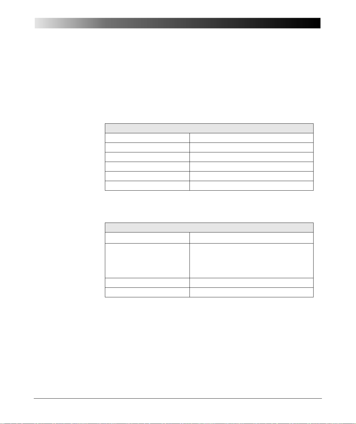
6.1 CMGPS in General
Table 6-1:
General technical
specifications of the
CMGPS
Technical Data
6 Technical Data
Guaranteed Features: The technical specifications indicated in this chapter are
valid for 1 year from date of delivery.
CMGPS in general
Dimensions (w x h x d) 140 x 70 x 40 mm (5.5 x 2.25 x 1.6 in)
Housing Metal, front panel with foil coating
Weight 440 g (0.88 lb)
Ambient temperature 0 ... 50 °C (32 ... 122 °F)
Storage and transport –25 ... +70 °C (–13 ... +158 °F)
Humidity range 5 ... 95 % relative humidity; non-condensing
6.2 GPS Receiver
Table 6-2:
Technical specifications
GPS receiver
GPS receiver
Number of SV
1
TTFF (time to first fix)
2
12 (satellites)
Typ. 5 minutes
(for a set accuracy of < ±1 µs)
Typ. 3 minutes
(for a set accuracy of < ±10 µs)
Position fault < 5 m (16.4 ft) [1 σ]
Identification antenna status OK, short circuit, defective
1. SV = "space vehicle". Max. number of satellites the receiver can use to determine position or
time. The satellites providing the highest signal quality are considered. In general, the receiver
only needs 4 - 5 satellites to determine position and time — depending on the signal quality.
2. TTFF = Time span the CMGPS needs to receive a sufficient number of satellite signals after
switching on (to be "locked" to the signals). The higher the synchronization accuracy set via
software (optimum: abs. error < ± 1
μs), the longer the time span will be.
35
Page 36
GPS Synchronization Unit CMGPS
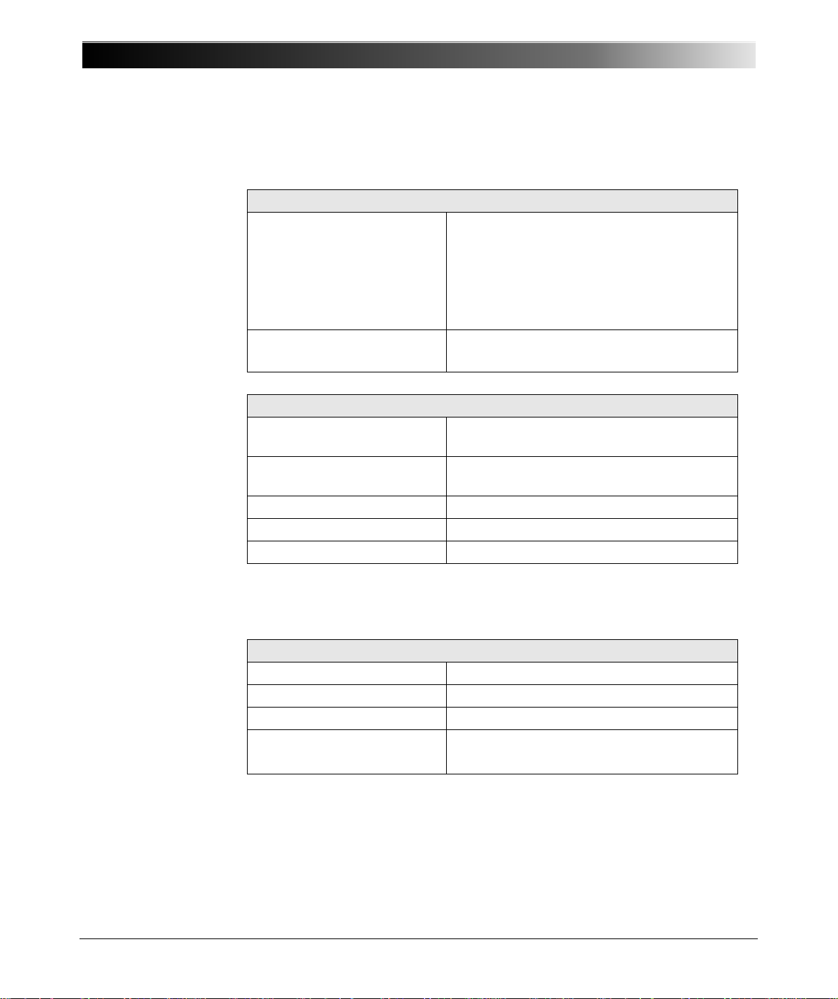
6.3 Power Supply
Table 6-3:
Power supply
Power supply unit
Supply voltage
Power supply unit
Rated current input
Frequency
• nominal freq.:
• admissible range:
Output voltage
Rated current output
Power supply CMGPS
Nominal supply voltage
CMGPS
Admissible range of power
supply voltage
Power consumption 2.5 W
Connection Reverse polarity protected
Protection class II
100 - 240 V
400 mA
50/60 Hz
47 - 63 Hz
18 V
DC
840 mA
18 V
+8 V
/ 150 mA
DC
... +30 V
DC
AC
DC
36
Table 6-4:
Antenna
6.4 Antenna
Antenna
Antenna Active
Connection of device Coaxial (SMA socket)
Connection of antenna Screw-on type (SMA plug)
Antenna extension cable
1. There is an optional extension set of 2 x 20 m (2 x 60 ft.) with SMA adapters available for a total
extension of 40 m (120 ft.); refer to Table 8-1: ”Ordering information for the CMGPS
synchronization (set)” on page 43.
RG58 50
Ω coaxial cable, 15 m (45 ft.)
(approx. 1 dB/m or 0.3 dB/ft)
1
Page 37
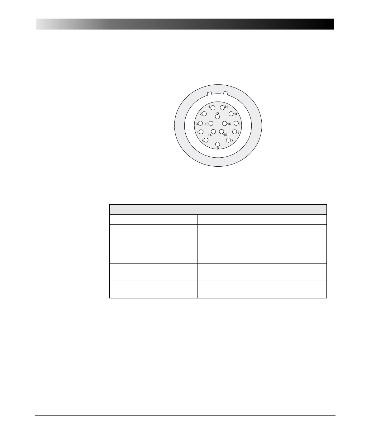
6.5 ext. Interf.
Figure 6-1:
16-pole LEMO™ socket
ext. Interf.
Table 6-5:
Technical data
ext. Interf. (output
Pulse out 1)
Technical Data
This interface serves to connect the CMGPS to the CMC test set by means of
the supplied connection cable VEHK0003 (see figure 3-3 on page 14).
ext. Interf. (output Pulse out 1)
Type CMOS output
Accuracy
Pulse length 200 ms
Pulse rate Configurable in steps of 1 second
Polarity of synchronization
signal
First synchronization point of
time
Absolute error < ± 1 µs
(1 s … 65535 s)
Configurable to descending or ascending
edge
Programmable
1
1. Accuracy of CMGPS. The synchronization of test sets depends on the accuracy set in the Test
Universe software. Also refer to chapters 5.1 ”Standard Accuracy Mode” and 5.2 ”Enhanced
Accuracy Mode”
The synchronization pulse is only put out if the CMGPS is able to meet the
accuracy configured by the software.
37
Page 38
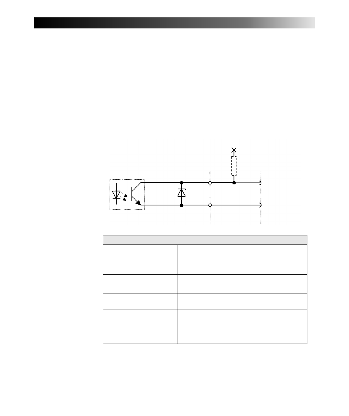
GPS Synchronization Unit CMGPS
At this interface the synchronization pulse of th e
CMGPS can be picked up potential free via an
internal opto-electronic coupler (open collector). At
present, the Test Universe software supports the
configuration of a pulse output only. Therefore,
Pulse out 2 is synchronous to Pulse out 1.
+ UB (max. 30 V)
30 V
Pull-up resistor
R
p
(optional)
Pulse out 2
Bin In +
GND
red +
black -
CMGPS CMC test set
6.6 Pulse Out 2 Interface
Figure 6-2:
Pulse out 2 interface
Figure 6-3:
Block diagram of the
Pulse out 2 interface
Table 6-6:
Technical specifications
Pulse out 2 interface
38
Interface Pulse out 2
Type Output by optoelectronic coupler (open collector)
Accuracy
Pulse length 200 ms
Pulse rate Configurable in steps of 1 s (1 s … 65535 s)
Polarity of synch. signal Configurable to falling or rising edge
First synchronization point
of time
Specifications of the open
collector output transistor:
•I
Cmax
•U
CEmax
1. Depending on accuracy set in the Test Universe software
The synchronization pulse is only put out if the CMGPS is able to meet the
accuracy configured by the software.
Absolute error < ±5 µs
Programmable
5mA
30 V (red socket +, black socket –)
1
Page 39
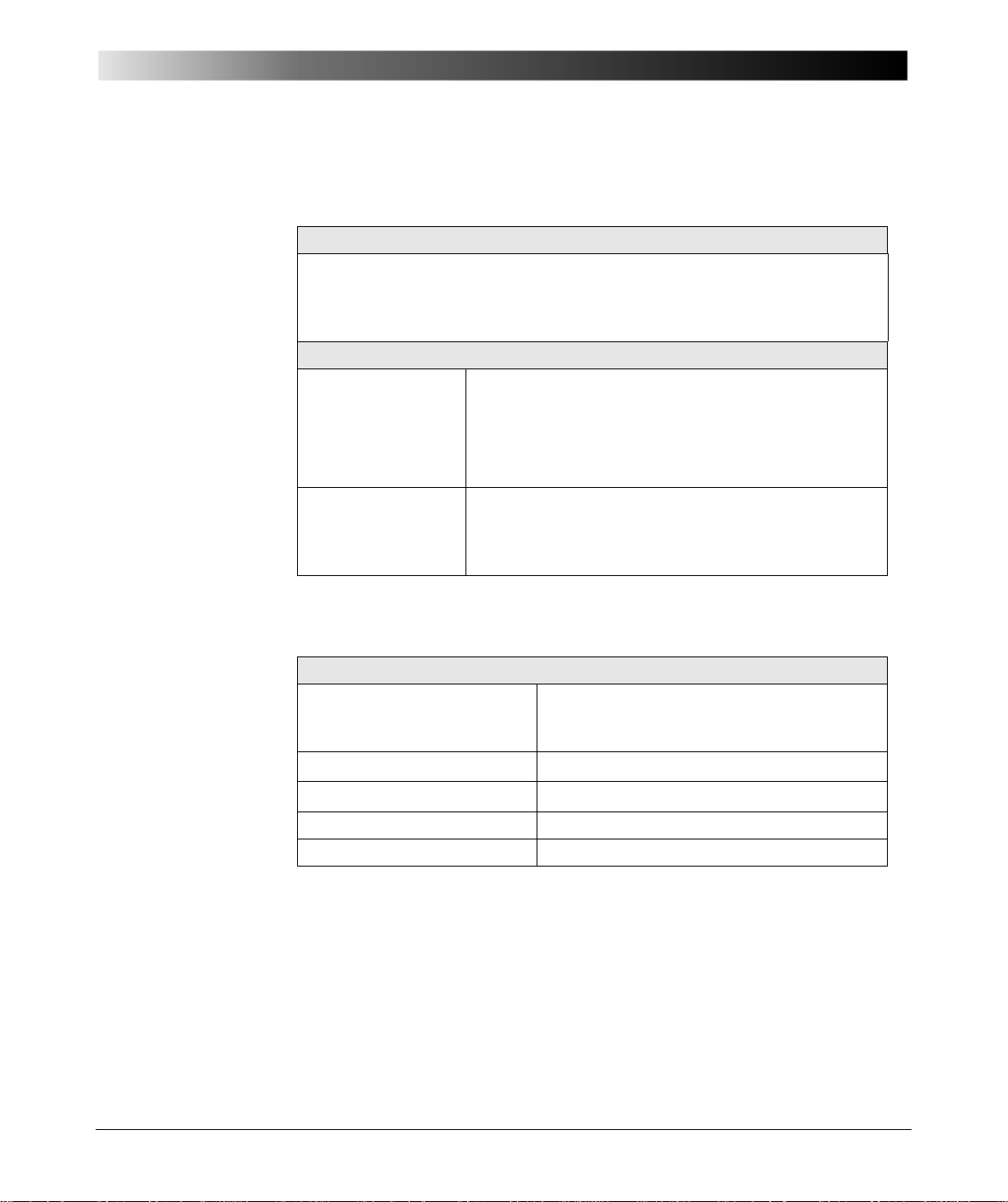
Table 6-7:
Electromagnetic
Compatibility
Technical Data
6.7 CE Conformity, Electromagnetic Compatibility
CE Conformity
The product adheres to the specifications of the guidelines of the council of the
European Community for meeting the requirements of the member states
regarding the electromagnetic compatibility (EMC) Directive 2004/108/EC and
the low voltage Directive 2006/95/EC.
Electromagnetic Compatibility (EMC)
Emission
6.8 Insulation Coordination
Table 6-8:
Insulation coordination
Europe
International
USA
EN 61326-1; EN 61000-6-4; EN 61000-3-2/3
IEC 61326-1; IEC 61000-6-4; IEC 61000-3-2/3
FCC Subpart B of Part 15 Class A
Immunity
Europe
International
EN 61326-1; EN 61000-6-2; EN 61000-4-2/3/4/5/6/11
IEC 61326-1; IEC 61000-6-2; IEC 61000-4-2/3/4/5/6/11
Insulation coordination
Insulation of Pulse out 2
Complies with EN 61010-1 and EN 60950-1
interface with regard to
housing and/or ext. Interf.
Max. operating voltage 250 V
Test voltage 3000 V
AC
AC
Air gap > 5 mm (0.2 in)
Creep path > 6 mm (0.24 in)
39
Page 40
GPS Synchronization Unit CMGPS
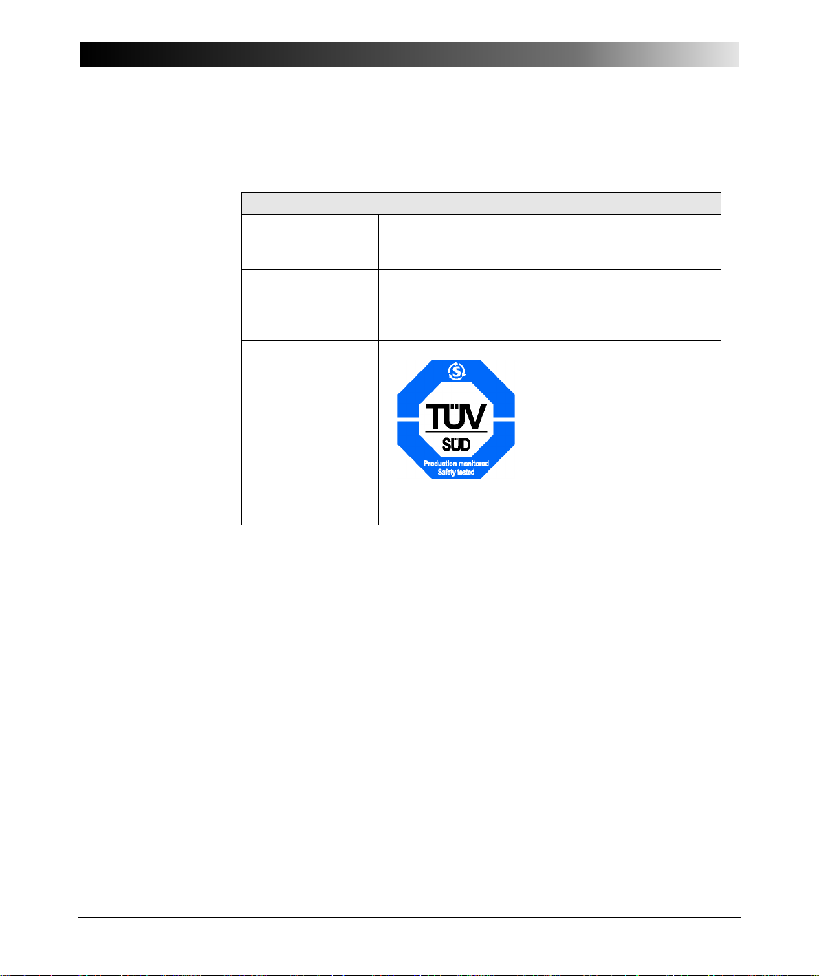
6.9 Safety Standards, Certificates
Table 6-9:
Safety Standards,
Certificates
Certified Safety Standards
Europe EN 61010-1
International
Insulation of Pulse out 2 interface with regard to
housing and/or ext. Interf. complies with EN 60950-1.
IEC 61010-1
USA
Canada
Certificate
UL 61010-1
CAN/CSA-C22.2 No 61010-1-04
Manufactured under an ISO9001 registered system.
40
Page 41
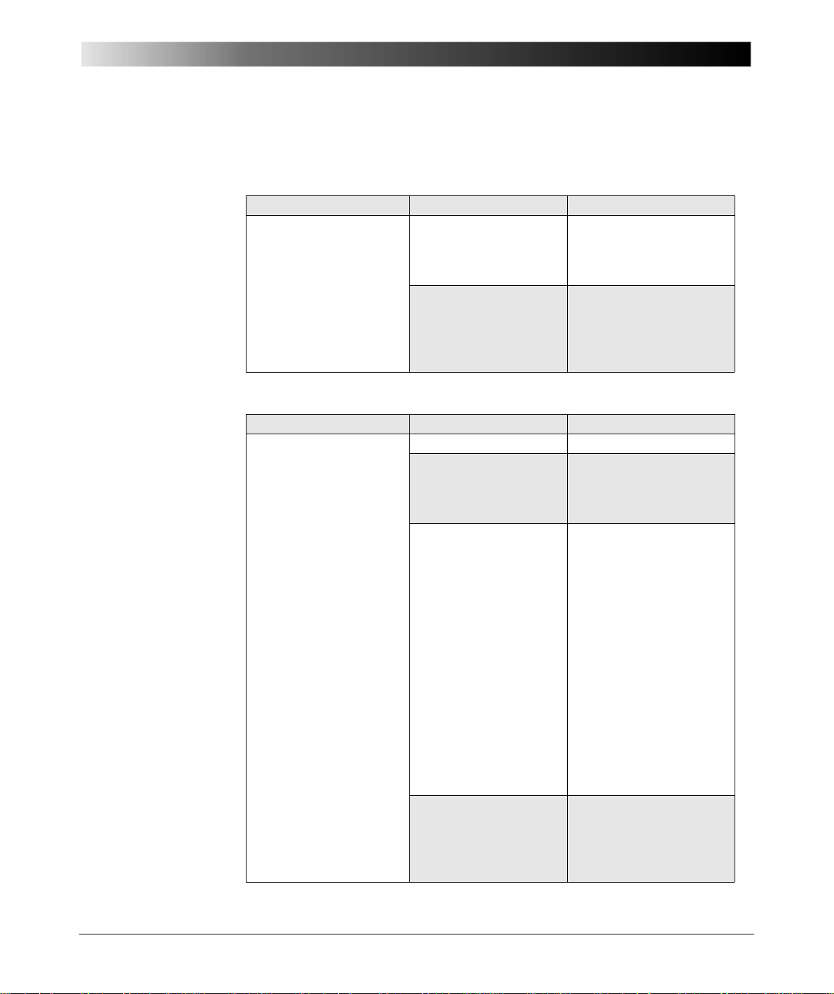
7 Faults, Possible Causes, Remedies
Table 7-1:
Faults, possible causes
and elimination - I
Table 7-2:
Faults, possible causes
and elimination - II
Fault Possible cause Remedy
CMGPS without power,
LED "ON" is off.
Fault Possible cause Remedy
Both LEDs
"Searching/Locked" and
"Pulse" are off, LED
"ON" is lit
Faults, Possible Causes, Remedies
Power supply unit
defective.
Check output voltage of
the power supply unit by
means of a voltmeter
(nominal value: 18 V
Malfunction of the
CMGPS.
Please contact the
OMICRON Technical
Support (see ”Contact
Information / Technical
Support” on page 45).
Antenna not connected Check connection.
Cable connection
antenna
⇔ CMGPS
defective.
Check screwed fittings
and contact quality of the
coaxial cable at each
connection.
Malfunction of
hardware.
Read out the fault
description via software.
For information how to do
that, start the
Test Universe Help from
the OMICRON
Start Page (or any test
module) and navigate to
the table of contents entry
--- Start Page ---. Click
OMICRON Start Page
and scroll down to the
subheader Support.
There you’ll find
Diagnosis &
Calibration.
Antenna defective. Please contact the
OMICRON Technical
Support (see ”Contact
Information / Technical
Support” on page 45).
DC
).
41
Page 42
GPS Syncronization Unit CMGPS
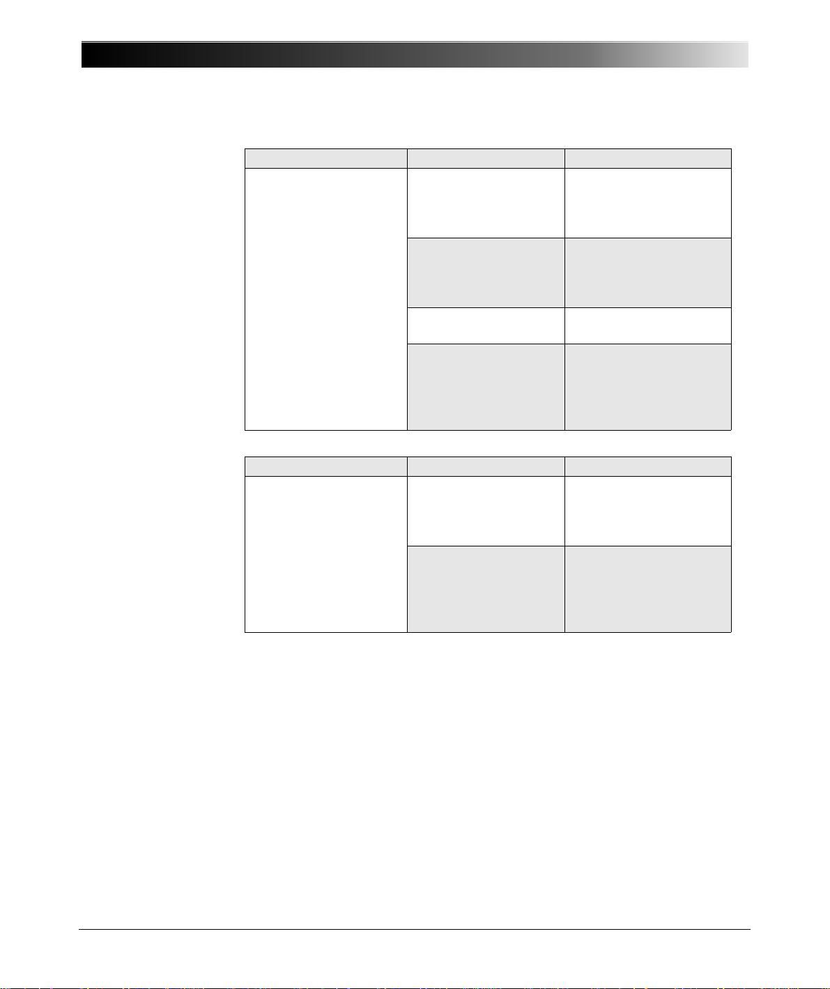
Table 7-3:
Faults, possible causes
and elimination - III
LED "Searching/Locked"
has been flashing for
approx. 20 minutes,
CMGPS cannot be
successfully locked to
the GPS signal (TTFF
considerably exceeded).
Table 7-4:
Faults, possible causes
and elimination - IV
LED "Searching/Locked"
is lit, CMGPS is locked
to the GPS signal, but
there is no
synchronization pulse.
Fault Possible cause Remedy
Cable connection
antenna
⇔ CMGPS
defective.
Check screwed fittings
and contact quality of the
coaxial cable at each
connection.
Position of antenna
inappropriate.
Place antenna in a more
exposed location that
provides sufficient open
sky.
Antenna or antenna
cable defective.
Malfunction of the
CMGPS.
Replace defective
component.
Please contact the
OMICRON Technical
Support (see ”Contact
Information / Technical
Support” on page 45).
Fault Possible cause Remedy
Timing parameter for
putting out the
synchronization pulse is
set wrong or too long.
Malfunction of the
CMGPS.
Check the settings by
means of the software. If
necessary change
settings.
Please contact the
OMICRON Technical
Support (see ”Contact
Information / Technical
Support” on page 45).
42
Page 43
8 Appendix
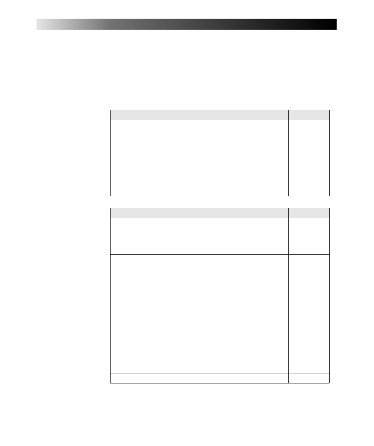
8.1 Ordering Information
Table 8-1:
Ordering information for
the CMGPS
synchronization (set)
Table 8-2:
Ordering information for
individual or optional
components
Appendix
CMGPS synchronization unit Part no.
CMGPS synchronization unit set, consisting of
VEHZ3000
– CMGPS synchronization unit (see figure 3-1 on page 13)
– power supply unit 100 - 240 V
AC
/18 V
, incl. plug-in
DC
adapter for various country-specific wall outlets
– active antenna
– 15 m (50 ft) antenna cable
– 16-pole LEMO connection cable CMGPS
⇔ CMC test set
– carrying bag
Individual and optional components Part no.
Power supply unit 100 - 240 V
AC
/18 V
, incl. plug-in adapter
DC
VEHZ1103
for various country-specific wall outlets (see figure 3-2 on page
13)
Active antenna (see figure 3-4 on page 14) VEHZ3001
Cables:
– 16-pole LEMO connection cable CMGPS
(see figure 3-3 on page 14)
– 15 m (50 ft) antenna cable (see figure 3-5 on page 15)
⇔ CMC test set
VEHK0003
VEHK3002
– 2 × 20 m (2 x 60 ft) antenna extension cable and SMA
adapter for an extension of 40 m (see figure 3-6 on page 15).
VEHZ3003
Note: when connecting VEHZ3003, VEHK3002 cannot be
used anymore.
Reference manual for CMGPS VESD0200
CMGPS carrying bag VEHP0020
CMIRIG-B interface unit with all accessories VEHZ1150
CMIRIG-B interface unit without accessories VEHZ1151
Connection cable CMIRIG-B
⇔ CMC test set VEHK0003
CMIRIG-B Reference Manual VESD1150
43
Page 44

GPS Syncronization Unit CMGPS
8.2 Cleaning
To clean the CMGPS, use a cloth dampened with isop ropanol alcohol or water.
Prior to cleaning, always unplug the CMGPS from the mains and disconnect
CMGPS from the CMC test set.
44
Page 45

Contact Information / Technical Support
Contact Information / Technical Support
North and South America
OMICRON electronics Corp. USA
12 Greenway Plaza, Suite 1510
Houston, TX 77046, USA
Phone: +1 713 830-4660 or 1 800 OMICRON
Asia, Pacific
OMICRON electronics Asia Ltd.
Suite 2006, 20/F, Tower 2
The Gateway, Harbour City
Kowloon, Hong Kong S.A.R.
Phone: +852 2634 0377
E-Mail: [email protected]
Web: http://www.omicron.at
Europe, Africa, Middle East
OMICRON electronics GmbH
Oberes Ried 1
6833 Klaus, Austria
Phone: +43 5523 507-333
For addresses of OMICRON offices with customer serv ice ce nt er s, re gio n al sale s
offices or offices for training, consulting and commissioning, please see the Contact
section of our Web site http://www.omicron.at
.
45
Page 46

Contact Information / Technical Support
46
Page 47

Index
Index
A
address
OMICRON addresses . . . . . . . . . . . . . . . 45
Antenna
CMGPS antenna input . . . . . . . . . . . . . . . 20
components list of CMGPS . . . . . . . . . . . 14
technical specifications . . . . . . . . . . . . . . 36
B
Banana sockets
Pulse out 2 interface . . . . . . . . . . . . . . . . 22
Binary input
synchronization pulse at the . . . . . . . . . . 22
triggering . . . . . . . . . . . . . . . . . . . . . . . . . 22
Block diagram of the CMGPS . . . . . . . . . . . . 23
D
data
technical data . . . . . . . . . . . . . . . . . . . . . 35
Designated use of CMGPS . . . . . . . . . . . . . . 9
Dimensions of CMGPS . . . . . . . . . . . . . . . . 35
E
electromagnetic compatibility . . . . . . . . . . . . 39
e-mail
OMICRON addresses . . . . . . . . . . . . . . . 45
EMC . . . . . . . . . . . . . . . . . . . . . . . . . . . . . . . 39
Example of use . . . . . . . . . . . . . . . . . . . . . . 29
ext. Interf. . . . . . . . . . . . . . . . . . . . . . . . . 21, 26
technical specifications . . . . . . . . . . . . . . 37
Extension cable for antenna
components of the CMGPS . . . . . . . . . . 15
F
C
CE conformity . . . . . . . . . . . . . . . . . . . . . . . . 39
certificates . . . . . . . . . . . . . . . . . . . . . . . . . . . 40
CMC56 without CMExif module . . . . . . . . . . 27
CMIRIG-B . . . . . . . . . . . . . . . . . . . . . . . . . . . 32
Components of the CMGPS . . . . . . . . . . . . . 13
Connection cable CMGPS - CMC . . . . . . . . . 14
Connections
antenna input of the CMGPS . . . . . . . . . . 20
power supply . . . . . . . . . . . . . . . . . . . . . . 19
contact information
OMICRON addresses . . . . . . . . . . . . . . . 45
Frequency range GPS . . . . . . . . . . . . . . . . . 11
G
GLONASS . . . . . . . . . . . . . . . . . . . . . . . . . . 11
GPS
technical principles . . . . . . . . . . . . . . . . . 11
what is GPS? . . . . . . . . . . . . . . . . . . . . . 11
GPS receiver
passive receiver . . . . . . . . . . . . . . . . . . . 11
technical specifications . . . . . . . . . . . . . . 35
47
Page 48

GPS Synchronization Unit CMGPS
H
hotline . . . . . . . . . . . . . . . . . . . . . . . . . . . . . . 45
Housing - technical specifications . . . . . . . . . 35
I
Insulation concept . . . . . . . . . . . . . . . . . . . . . 39
Interface Pulse out 2 . . . . . . . . . . . . . . . . . . . 22
IRIG-B time reference . . . . . . . . . . . . . . . . . . 32
N
NAVSTAR satellites . . . . . . . . . . . . . . . . . . . 11
O
Optoelectronic coupler - output Pulse out 2 . 22
T
Technical specifications CMGPS . . . . . . . . . 35
Technical Support . . . . . . . . . . . . . . . . . . . . 45
Test Universe software . . . . . . . . . . . . . . . . . 5
and pulse output "Pulse out 2" . . . . . . . . 22
Triggering via GPS . . . . . . . . . . . . . . . . . . . . 12
W
Web site
OMICRON Web site . . . . . . . . . . . . . . . . 45
Weight - technical specifications . . . . . . . . . 35
P
Power supply unit . . . . . . . . . . . . . . . . . . . . . 13
Pulse out 2 interface . . . . . . . . . . . . . . . . . . . 22
S
Safety standards . . . . . . . . . . . . . . . . . . . . . . 40
synchronization
via CMIRIG-B . . . . . . . . . . . . . . . . . . . . . . 32
via GPS . . . . . . . . . . . . . . . . . . . . . . . . . . 12
Synchronization point of time
at "Pulse out 2" . . . . . . . . . . . . . . . . . . . . 22
at the ext. Interf. . . . . . . . . . . . . . . . . . . . . 21
Synchronization pulse - time interval . . . . . . 27
48
 Loading...