

Page 1
CMC 356
User Manual
Page 2

&0&5HIHUHQFH0DQXDO
Article Number VESD2003 - Version CMC356.AE.4
© OMICRON electronics. All rights reserved.
This manual is a publication of OMICRON electronics.
All rights including translation reserved. Reproduction of any kind, e.g., photocopying, microfilming, optical
character recognition and/or storage in electronic data processing systems, requires the explicit consent of
OMICRON electronics.
Reprinting, wholly or in part, is not permitted. The product information, specifications, and technical data
embodied in this manual represent the technical status at the time of writing and are subject to change without
prior notice.
We have done our best to ensure that the information given in this manual is useful, accurate and entirely
reliable. However, OMICRON electronics does not assume responsibility for any inaccuracies which may be
present.
The user is responsible for every application that makes use of an OMICRON product.
OMICRON electronics translates this manual from the source language English into a number of other
languages. Any translation of this manual is done for local requirements, and in the event of a dispute between
the English and a non-English version, the English version of this manual shall govern.
2
Page 3

Table of Contents
TABLE OF CONTENTS
Preface...................................................................................................................... 7
Safety Instructions .................................................................................................. 8
1 Designated Use ............................................................................................ 11
2 Introduction .................................................................................................. 12
2.1 Options Available for the CMC 356 Test Set ................................................................. 12
3 Operating the CMC 356 ............................................................................... 13
3.1 System Components ..................................................................................................... 13
3.2 Safe Use of the Connecting Cables ............................................................................... 14
3.2.1 Test Lead Adapter for Non-Safety Sockets ....................................................... 14
3.3 Regular Test Leads for Safety Sockets .......................................................................... 15
3.3.1 Terminal adapters.............................................................................................. 15
3.3.2 M4 (0.15") Cable Lug Adapters ......................................................................... 16
3.3.3 M5 (0.20") Cable Lug Adapters ......................................................................... 16
3.4 Starting the Test System ................................................................................................ 17
4 Setup and Function ..................................................................................... 19
4.1 Block Diagram ............................................................................................................... 20
4.1.1 Voltage Output (Voltage Amplifier) .................................................................... 21
4.1.2 Current Output (Current Amplifier)..................................................................... 22
4.1.3 Binary / Analog Input (Binary Inputs 1 - 10) ....................................................... 23
4.1.4 Binary Output..................................................................................................... 23
4.1.5 AUX DC (DC Power for Test Objects) ............................................................... 24
4.1.6 CPU ................................................................................................................... 25
4.1.7 Power Supplies (DC-DC)................................................................................... 25
4.2 Signal Generation.......................................................................................................... 25
4.2.1 Accuracy and Signal Quality .............................................................................. 26
5 Connections and Interfaces ........................................................................ 27
5.1 Front Panel Connections ............................................................................................... 27
5.1.1 Generator Combination Socket for VOLTAGE OUTPUT and CURRENT
OUTPUT ............................................................................................................ 30
3
Page 4

CMC 356 Reference Manual
5.2 Connections on the Back Panel .................................................................................... 32
5.2.1 Ethernet Ports ETH1 and ETH2 ........................................................................ 32
5.2.2 ! Button .............................................................................................................. 33
5.2.3 Associate Button................................................................................................ 33
5.2.4 Status LED A, B................................................................................................. 34
5.2.5 Ethernet / Network Settings ............................................................................... 34
5.2.6 SELV Interfaces................................................................................................. 36
5.2.6.1 External Interface ("ext. Interf.") ......................................................... 36
5.2.6.2 LL out 1-6 (Low Level Outputs 1-6) .................................................... 37
5.2.6.3 LL out 7-12 (Low Level Outputs 7-12) - Option "LLO-2"..................... 37
6 Technical Data .............................................................................................. 39
6.1 Main Power Supply........................................................................................................ 39
6.2 Insulation Coordination.................................................................................................. 40
6.3 Outputs .......................................................................................................................... 41
6.3.1 Extended Frequency Range .............................................................................. 42
6.3.2 Current Outputs ................................................................................................. 43
6.3.3 Voltage Outputs ................................................................................................. 48
6.3.3.1 Power Diagram for Three-Phase Operation ....................................... 49
6.3.3.2 Power Diagram for Single-Phase Operation ...................................... 50
6.3.4 Operational Limits in Conjunction with Mains Supply ........................................ 51
6.3.5 Low Level Outputs "LL out" for External Amplifiers ........................................... 52
6.3.6 Low-Level Binary Outputs ("ext. Interf.")............................................................ 54
6.3.7 Binary Output Relays......................................................................................... 56
6.3.8 DC Supply (AUX DC)......................................................................................... 57
6.4 Inputs.............................................................................................................................. 58
6.4.1 Binary Inputs...................................................................................................... 58
6.4.2 Counter Inputs 100 kHz (Low Level) ................................................................. 61
6.5 Technical Data of the Ethernet Ports.............................................................................. 63
6.5.1 The NET-1B Board ............................................................................................ 63
6.5.2 The NET-1 Board............................................................................................... 64
6.6 Environmental Conditions............................................................................................... 65
6.6.1 Climate............................................................................................................... 65
6.6.2 Shock and Vibration........................................................................................... 65
6.7 Mechanical Data............................................................................................................ 65
6.8 Cleaning ........................................................................................................................ 65
6.9 Safety Standards, Electromagnetic Compatibility (EMC) and Certificates ..................... 66
6.10 Option ELT-1 ................................................................................................................. 67
4
Page 5

Table of Contents
6.10.1 General Data ..................................................................................................... 68
6.10.2 Analog DC Input (VDC, IDC) ............................................................................. 69
6.10.3 Accuracy of the Analog DC Input....................................................................... 70
6.10.4 Measuring Currents ........................................................................................... 71
6.10.5 Accuracy of Binary/Analog Inputs with Option ELT-1 ........................................ 72
6.10.6 Multimeter Mode ................................................................................................ 73
6.10.6.1 Accuracy of AC Measurements .......................................................... 74
6.10.6.2 Channel Cross-Talk............................................................................ 76
6.10.6.3 Accuracy of Phase Measurement....................................................... 77
6.10.6.4 Accuracy of Frequency Measurement................................................ 79
6.10.6.5 Accuracy of Power Measurement....................................................... 80
6.10.7 Harmonic Analysis ............................................................................................. 84
6.10.7.1 Accuracy of Frequency Measurement................................................ 85
6.10.7.2 Accuracy of Amplitude Measurement................................................. 86
6.10.7.3 Accuracy of Phase Measurement....................................................... 87
6.10.8 Transient Recording .......................................................................................... 88
6.10.9 Trend Recording ................................................................................................ 89
6.11 Option LLO-2 (Low Level Outputs)................................................................................. 90
7 Increasing the Output Power, Operating Modes ....................................... 91
7.1 Safety Instructions for High Current Output................................................................... 91
7.2 Single-Phase Operation of the CMC 356 ...................................................................... 92
7.2.1 1 x 32 A High Burden Mode (L-L-L-L)................................................................ 92
7.2.2 1 x 64 A High Burden and High Current Mode (L-L).......................................... 93
7.2.3 1 x 128 A High Current Mode (LL-LN) ............................................................... 94
7.2.4 Single-Phase Voltage ........................................................................................ 95
7.3 Two-Phase Operation..................................................................................................... 96
7.3.1 2 x 64 A High Current Mode (LL-LN) ................................................................. 96
7.3.2 2 x 32 A High Burden Mode (L-L) ...................................................................... 97
7.4 Three-Phase Current Mode with High Burden ............................................................... 98
7.5 Operation with External Amplifiers ................................................................................. 99
8 Troubleshooting ......................................................................................... 101
8.1 Troubleshooting Guide ................................................................................................ 101
8.2 Potential Errors, Possible Causes, Remedies............................................................. 102
8.3 Overheating .................................................................................................................. 103
5
Page 6

CMC 356 Reference Manual
9 CMC 356-Related Products and Accessories ......................................... 105
9.1 CMA Current Amplifiers & CMS Voltage Amplifiers .................................................... 105
9.2 CMControl-6 ................................................................................................................. 106
9.3 Time Synchronization Accessories............................................................................... 107
9.3.1 CMGPS............................................................................................................ 107
9.3.2 CMIRIG-B ........................................................................................................ 109
9.4 100TX to 100FX-SC Converter .................................................................................... 111
9.5 Current Clamp C-PROBE1........................................................................................... 112
9.6 Accessories for Meter Testing ...................................................................................... 113
9.6.1 Scanning Head OSH256 ................................................................................. 113
9.6.2 Interface Box IFB256 ....................................................................................... 114
9.6.3 Scanning Head TK 326.................................................................................... 115
9.6.4 Scanning Head TVS 6.15/1 ............................................................................. 116
9.6.5 Adapter Cable for Scanning Heads ................................................................. 117
9.6.6 CMLIB B .......................................................................................................... 118
9.6.7 CMLIB A .......................................................................................................... 119
9.6.8 CPOL Polarity Tester....................................................................................... 120
9.6.9 Connection Cable for REF 54x Relays (ABB) with Low Level Signal Inputs ... 121
9.6.10 C-Shunt............................................................................................................ 122
9.7 Wiring Accessories ....................................................................................................... 123
9.7.1 Standard Delivery Scope ................................................................................. 123
9.7.2 Optional CMC Wiring Accessory Package ...................................................... 124
9.8 Ordering Information..................................................................................................... 127
Appendix .............................................................................................................. 133
Contact Information / Technical Support ...........................................................137
Index ..................................................................................................................... 139
6
Page 7

Preface
PREFACE
The purpose of this reference manual is to familiarize users with the
CMC 356 test set and to show how to properly use it in various application
areas.
The manual contains important tips on how to use the CMC 356 safely,
properly, and efficiently. Its purpose is to help you avoid danger, repair
costs, and down time as well as to help maintain the reliability and life of the
CMC 356.
This manual is to be supplemented by existing national safety standards for
accident prevention and environmental protection.
The reference manual should always be available at the site where the
CMC 356 is used. It should be read by all personnel operating the test set.
Note: The OMICRON Test Universe software also installs a PDF version of
this reference manual. It can directly be opened by a mouse-click from the
help topic "User Manuals of OMICRON Test Universe".
In addition to the reference manual and the applicable safety regulations in
the country and at the site of operation, the usual technical procedures for
safe and competent work should be heeded.
Note: This reference manual describes the CMC 356 hardware - that is, the
physical test set. In order to get familiar with the software for controlling and
configuring the CMC 356, please refer to the software manuals and/or the
OMICRON Test Universe Help.
For Your Safety Please Note
The CMC 356 test set can output life-hazardous voltages and currents.
Throughout the manual, this symbol indicates special safety-relevant
notes/directions linked to the possibility of touching live voltages and/or
currents. Please thoroughly read and follow those directions to avoid life-
hazardous
This symbol indicates potential hazards by electrical voltages/currents
caused by, for example, wrong connections, short-circuits, technically
inadequate or faulty equipment or by disregarding the safety notes of the
following sections.
situations.
7
Page 8

CMC 356 Reference Manual
SAFETY INSTRUCTIONS
Before operating the CMC 356 test set, carefully read the following
safety instructions.
Only operate (or even turn on) the CMC 356 after you have read this
reference manual and fully understood the instructions herein.
The CMC 356 may only be operated by trained personnel. Any
maloperation can result in damage to property or persons.
Rules for Use
•The CMC 356 should only be used when in a technically sound
condition. Its use should be in accordance with the safety regulations for
the specific job site and application. Always be aware of the dangers of
the high voltages and currents associated with this equipment. Pay
attention to the information provided in the reference manual and the
software documentation.
•The CMC 356 is exclusively intended for the application areas specified
in section 1, "Designated Use" on page 11. The manufacturer/
distributors are not liable for damage resulting from unintended usage.
The user alone assumes all responsibility and risk.
• The instructions provided in this reference manual and the associated
software manuals are considered part of the rules governing proper
usage.
• Do not open the CMC 356 or remove any of its housing components.
Orderly Practices and Procedures
• The reference manual (or its "electronic PDF pendant", which is installed
to your computer with the OMICRON Test Universe software) should
always be available on site where the CMC 356 is used.
Note: The OMICRON Test Universe software also installs a PDF version
of this reference manual. It can directly be opened by a mouse-click from
the help topic "User Manuals of OMICRON Test Universe". The
Test Universe Help can be launched by clicking Help on the Start Page.
• Personnel assigned to using the CMC 356 must have read this reference
manual and fully understood the instructions herein.
• Do not carry out any modifications, extensions or adaptations at the
CMC 356.
8
Page 9

Safety Instructions
Operator Qualifications
• Testing with the CMC 356 should only be carried out by authorized and
qualified personnel.
• Personnel receiving training, instruction, direction, or education on the
CMC 356 should remain under the constant supervision of an
experienced operator while working with the equipment.
Safe Operation Procedures
• Follow the instructions in sections 3.2 and 3.4 that describe the safe use
of the connecting cables and how to set the CMC 356 into operation.
•The CMC 356 must only be used from a power outlet that has a
protective earth.
• Do not block the access to safety-relevant test set components like the
main power switch or the power cord. In cases of an emergency, these
components need free and quick access.
• Do not connect any of the front panel VOLTAGE/CURRENT OUTPUTS
1 ... 3 or VOLTAGE OUTPUT 4, respectively, to protective earth. The N
sockets, however, may be connected to protective earth.
• When connecting to the banana plug sockets, only use cables with
4 mm/0.16 " safety banana connectors and plastic housing. Always
insert plugs completely.
• Before connecting and disconnecting test objects, verify that all outputs
have been turned off. Never connect or disconnect a test object while the
outputs are active.
• When disconnecting power supply cables or test leads, always start from
the device feeding the power or signal.
• All sockets on the front panel are to be considered dangerous with
working voltages up to 300 V
respective requirements to connect to the equipment.
• Red Signal Light :
If the voltage on any of the four voltage outputs or on the "AUX DC"
output exceeds 42 V, the associated signal light lights up.
• Do not insert objects (e.g., screwdrivers, etc.) into the sockets or into the
ventilation slots.
• Do not operate the CMC 356 under wet or moist conditions
(condensation).
. Only use cables that meet these
rms
9
Page 10

CMC 356 Reference Manual
• Do not operate the CMC 356 when explosive gas or vapors are present.
• The SELV interface (SELV = S
"Host Interf." or “ETH1”, "LL out" (L
should only have external devices connected that meet the requirements
for SELV equipment according to EN 60950 or IEC 60950.
• For applications drawing DC current: The load may not exceed 3 mH
because of dangerous feedback current.
• When setting up the CMC 356, make sure that the air slots on the back,
top, and bottom of the test set remain unobstructed.
• Voltages up to 1 kV can be present inside the CMC 356! Therefore,
opening the CMC 356 is only permitted by qualified experts either at the
factory or at certified external repair centers.
•If the CMC 356 is opened by the customer, all guarantees are
invalidated.
• CMC 356 Ethernet functionality (see section 5.2.1, "Ethernet Ports ETH1
and ETH2" on page 32):
- It is a product of laser class 1 (EN 60825, IEC 60825).
- Connect ETH1 only to Ethernet ports.
•If the CMC 356 seems to be functioning improperly, please contact the
OMICRON Tecnical Support (see section "Contact Information /
Technical Support" on page 137).
afety Extra Low Voltage) of the CMC 356 -
ow Level Outputs), "ext. Interf." -
10
Changing the Power Fuse
• Unplug the power cord between the test set and the power source.
• The fuse is located at the back of the test set.
• Fuse type: T12.5 AH 250 V (wire fuse 5 × 20 mm).
For safety reasons please use only fuse types recommended by the
manufacturer. Refer to 6.1, "Main Power Supply" on page 39 for more
information.
Page 11

1DESIGNATED USE
The CMC 356 is a computer-controlled test set for the testing of:
• protection relays
• transducers
• energy meters
• PQ (power quality) analyzers.
In addition to the test functions, optional high-performance measurement
functions [0 Hz (DC) ... 10 kHz] for ten analog inputs are available.
The CMC 356 is part of the OMICRON Test Universe which, in addition to
the physical test set, consists of a test software for a computer with
Windows
current amplifiers, GPS or IRIG-B synchronization units or other
accessories.
1
operating system, and, when needed, external voltage and/or
Designated Use
Features of the CMC 356:
• Output of test quantities:
-4 × voltage
- two galvanically separated three-phase current outputs.
• Capability of protection testing with IEC 61850 devices.
• Control of external amplifiers (up to 12 additional test signals) through
the low-level interface.
• Supply of DC voltages to the test object.
• Output of binary signals.
• Capture of binary signals and counter impulses.
• Option ELT-1:
Measurement and analysis of DC and AC voltages and currents by
means of a clip-on probe (refer to section 6.10, "Option ELT-1" on page
67) or a measurement shunt.
Any other use of the CMC 356 is considered improper and may result in
damage to property or persons.
1
Windows is a US registered trademark of Microsoft Corporation.
11
Page 12

CMC 356 Reference Manual
2INTRODUCTION
2.1 Options Available for the CMC 356 Test Set
The CMC 356 is a part of the OMICRON Test Universe which, in addition to
the physical test set, consists of a test software for a computer with
Microsoft Windows operating system, and, when needed, external voltage
and/or current amplifiers, GPS or IRIG-B synchronization units or other
accessories (refer to section 9, "CMC 356-Related Products and
Accessories" on page 105).
This reference manual describes the hardware of the CMC 356. The
configuration and control of the CMC 356 is carried out by the test software
of the OMICRON Test Universe. For more detailed information, please read
the user manuals and the OMICRON Test Universe Help.
Note: The OMICRON Test Universe software also installs a PDF version of
this reference manual. It can directly be opened by a mouse-click from the
Test Universe Help topic "User Manuals".
The following options are available for the CMC 356 test set:
• ELT-1
This hardware option enables:
• Measurement of analog signals using the combined
BINARY / ANALOG INPUT sockets.
• High-precision measurement of DC signals using the ANALOG DC
INPUT sockets.
For detailed information, please refer to section 6.10, "Option ELT-1" on
page 67).
• LLO-2 (low level outputs 7-12)
SELV interface connector holding two independent generator triples
(SELV = S
analog signal sources can serve to either control an external amplifier or
to directly provide small signal outputs.
For more information please refer section 6.3.5, "Low Level Outputs
"LL out" for External Amplifiers" on page 52.
afety Extra Low Voltage). These six additional high accuracy
12
Page 13

• FL-6
In a number of countries (e.g., Japan), the export of multiphase
generators able to output steady signals with a frequency between
600 Hz and 2000 Hz is not permitted.
The FL-6 option constraints the maximum fundamental frequency that
the test set can generate to 599 Hz. Test sets with the FL-6 option can
therefore be exported without any restrictions (refer to 6.3, "Outputs" on
page 41).
3OPERATING THE CMC 356
Only operate (or even turn on) the CMC 356 after you have read this
reference manual and fully understood the instructions herein.
3.1 System Components
Operating the CMC 356
Before operating the CMC 356 for the first time, use the packing list to verify
that all components of the test system are available.
To set the CMC 356 into operation you need the following components:
• CMC 356 with (mains) power cable
• Connecting cable CMC 356 ↔ PC
• Connecting cable CMC 356 ↔ test object
• PC equipped with an Ethernet port and the OMICRON Test Universe
software.
13
Page 14
CMC 356 Reference Manual
Retractable sleeve
↔
Safety socket of, for example,
the CMC 356 test set.
↔
Regular test lead
Non-safety socket
Test lead adapter
3.2 Safe Use of the Connecting Cables
3.2.1 Test Lead Adapter for Non-Safety Sockets
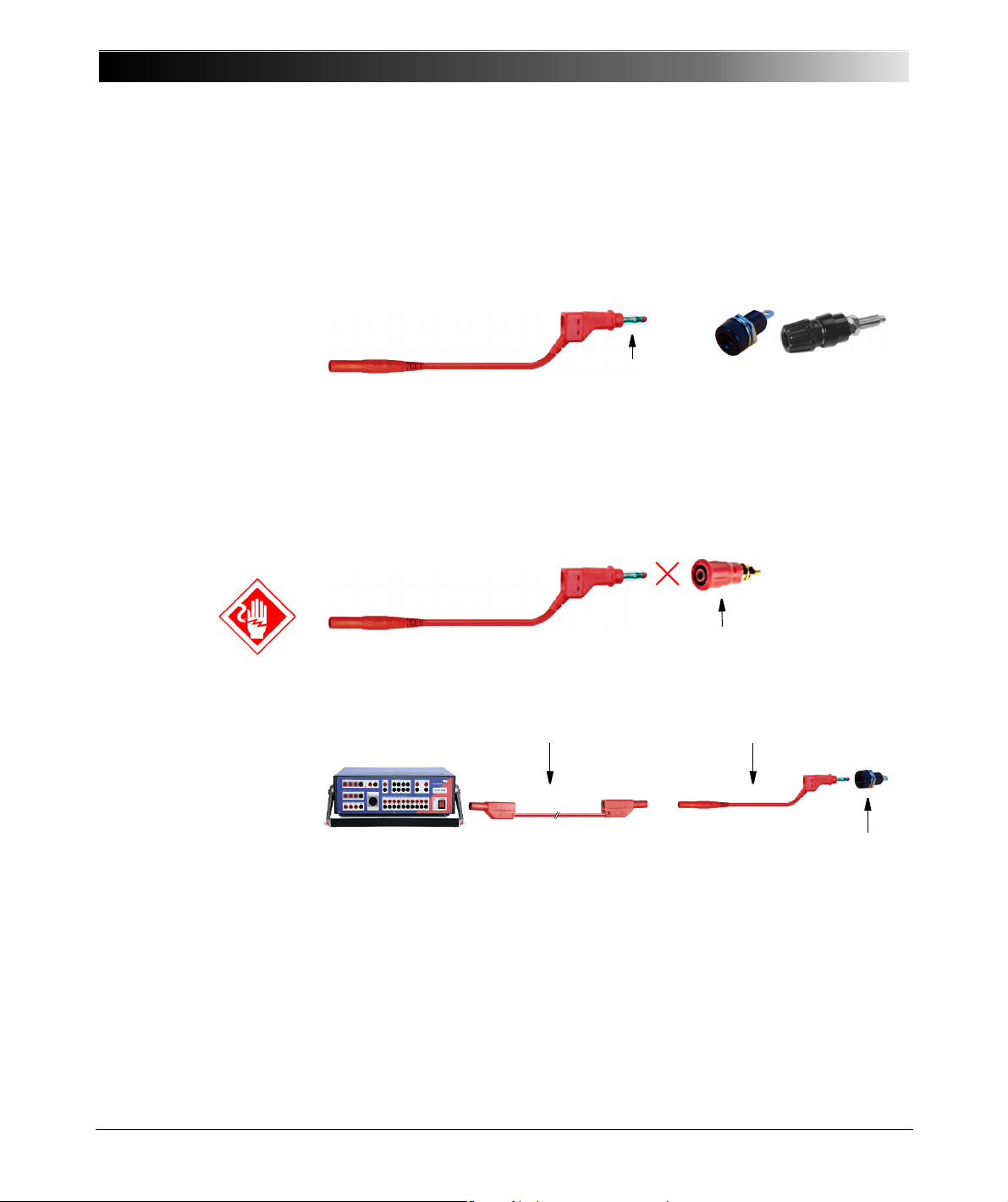
The optional CMC Wiring Accessory Package includes flexible test lead
adapters of 5 cm/2 " length with a retractable sleeve (6 x black, 6 x red).
These test leads are to be used as adapters, only. They are intended to
make the 4 mm/0.16 " banana plugs of the standard test leads fit into
non-safety sockets (see illustration above).
Never directly insert one of these retractable sleeves into a CMC 356
output socket at the front of the test set. This does not comply with the
designated purpose of these leads and is contrary to the safety regulations.
14
Plug only the regular test leads of 2.0 m/6 ft. length into the CMC 356
output safety sockets.
Page 15
3.3 Regular Test Leads for Safety Sockets
Regular test lead
or to safety socket,
e.g., at test object.
CMC 356 test set
or amplifier
to terminal strip
↔
Regular test lead
Terminal adapter
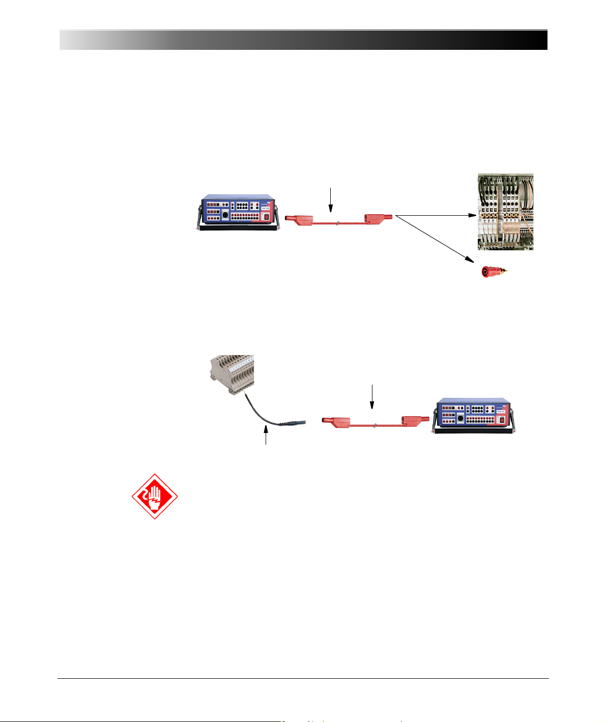
Use the regular test leads of 2.0 m/6 ft. length to connect the CMC 356
output to other safety sockets of, for example, amplifiers, test objects or to
banana adapters in control cabinets.
3.3.1 Terminal adapters
The optional CMC Wiring Accessory Package includes flexible terminal
adapters to connect the regular test leads to screw-clamp terminals.
Operating the CMC 356
The terminal adapters have blank ends. Therefore, turn off the voltage
before connecting these adapters. Always insert an adapter with its blank
end into the terminal strip first, and fasten it before connecting it to a test
lead.
15
Page 16
CMC 356 Reference Manual
↔
Regular test lead
M4 (0.15") cable lug adapter
↔
Regular test lead
M5 (0.20") cable lug adapter
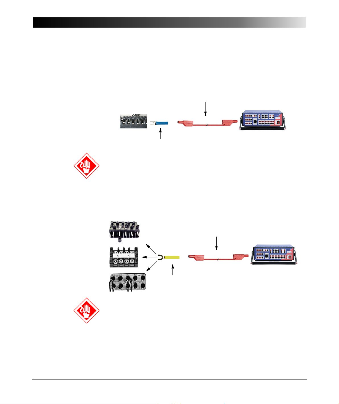
3.3.2 M4 (0.15") Cable Lug Adapters
3.3.3 M5 (0.20") Cable Lug Adapters
The optional CMC Wiring Accessory Package includes M4 (0.15") cable lug
adapters to connect regular test leads to screw-clamp terminals of
SEL/ABB/GE relays (and others).
The cable lugs have blank ends. Therefore, turn off the voltage before
connecting such a lug. Always insert the cable lug with its blank end into the
terminal strip first, and fasten it, before connecting it to a test lead.
The optional CMC Wiring Accessory Package includes M5 (0.20") cable lug
adapters to connect regular test leads to common and most widespread
screw-clamp terminal types.
The cable lugs have blank ends. Therefore, turn off the voltage before
connecting such a lug. Always insert the cable lug with its blank end into the
terminal strip first, and fasten it, before connecting it to a test lead.
16
Page 17
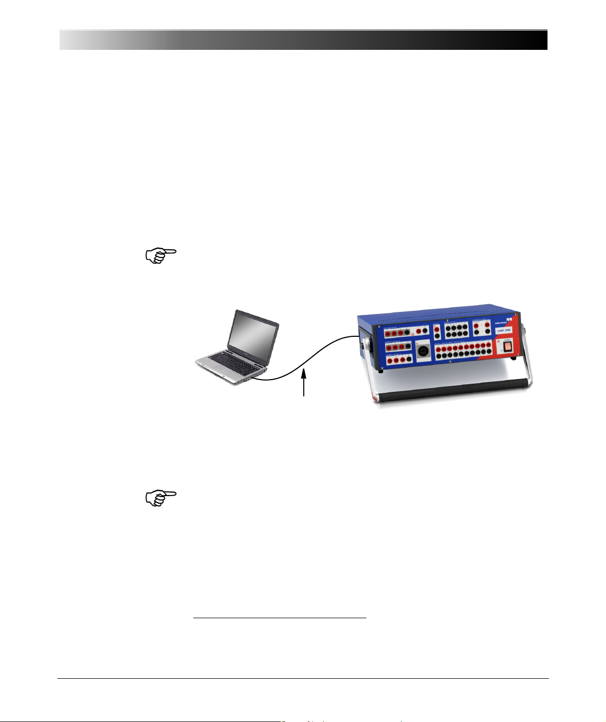
3.4 Starting the Test System
OMICRON-supplied connecting cable
Figure 3-1:
Connecting the CMC 356
to the computer
Operating the CMC 356
The following description assumes that the computer has been set up and
that the test software for the OMICRON Test Universe has been installed.
Detailed instructions for installing the software for the OMICRON Test
Universe can be found in the software manual "The Concept".
This description refers both to the computer and to the CMC 356. It does not
take into consideration any external devices. If the system is driven by
external amplifiers, follow the instructions in section 7.5, "Operation with
External Amplifiers" on page 99.
When setting up the CMC 356, it is most important to make sure that the
ventilation slots remain unobstructed.
Connecting the System Components:
1. Connect the CMC 356 to the PC with the supplied connecting cable1:
• CMC 356: Connector ETH1 at the rear sinde of the test set
• PC: Ethernet port (labeled “EtherNET”, “LAN” or similar).
For instructions to help you to incorporate network-capable CMC test
sets, such as the CMC 356 into a computer network, please refer to
the manual "Network-based CMC Test Sets". This manual is provided
in PDF format; its name is Network-based test sets.pdf. It is
available on your hard disk at
Test Universe installation folder\Test Universe\Doc\.
1
To ensure the required EMC compatibility, we recommended to only use the OMICRONsupplied connecting cable.
17
Page 18

CMC 356 Reference Manual
2. Connect the CMC 356 test set to the mains.
3. Turn on both devices.
4. Start the OMICRON Tes t U ni ver s e software.
A comprehensive hardware test is carried out on the CMC 356. In the
process, switching sounds from relays in the CMC test set can be heard.
If any irregularities are determined during the course of this self-test, the
software displays a corresponding error message on the PC monitor
(refer to section 8, "Troubleshooting" on page 101).
18
Page 19

Setup and Function
4SETUP AND FUNCTION
The computer-controlled OMICRON test system employs the concept of a
functional division between the software running on the computer and the
CMC 356 hardware connected to the test object.
OMICRON Test Universe test software running on the computer
• controls the test signals
• processes measurement data
• creates reports
• generates data entries.
The CMC 356 test set
• creates test signals (currents, voltages, binary signals)
• measures the reaction (analog and binary) from the test object
• supplies DC-current to test objects.
19
Page 20
CMC 356 Reference Manual
1* Note regarding the hardware option ELT-1:
The hardware option ELT-1 enables the measurement of analog signals
using the CMC 356. In the standard configuration (CMC 356 without option
ELT-1), the inputs BINARY/ANALOG INPUT 1 - 10 can only be used as
binary inputs, and DC inputs are not available.
1*
1*
DC
AC
Main Grou p
SELV Group
AUX DC
Internal
Supplies
VOLTAGE
CURRENT A
CURRENT B
CPU
System Control
(Signa l Genera tor)
PE
Mains
Host
Interface
DC DC
PC
Ext.
Ampl.
Counter
1,2
Bin. Out
11...14
CMGPS
IRIG-B
34
21
BINARY OUTPUT
LL out
7-12
(optional)
LL out
1-6
ext.
Interf.
U
DC
I
DC
ADC
ANALOG DC INPU TS
AFE
AFE
9
86
5
4
3
21
BINARY/ANALOG INPUT
working i solation
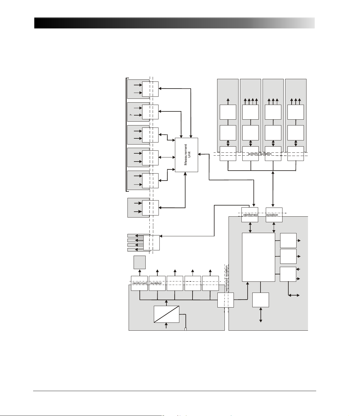
4.1 Block Diagram
Figure 4-1:
Main block diagram of
the CMC 356
10
AFE
DC
0...264V
4 x 0...300V
3 x 0...32A
3 x 0...32A
AFE
AFE
Contro l AUX DC
VOLTAGE
OUTPUT
Contro l
CURRENT
OUTPUT A
Contro l
CURRENT
OUTPUT B
Contro l
Ext.
Ampl.
20
Page 21
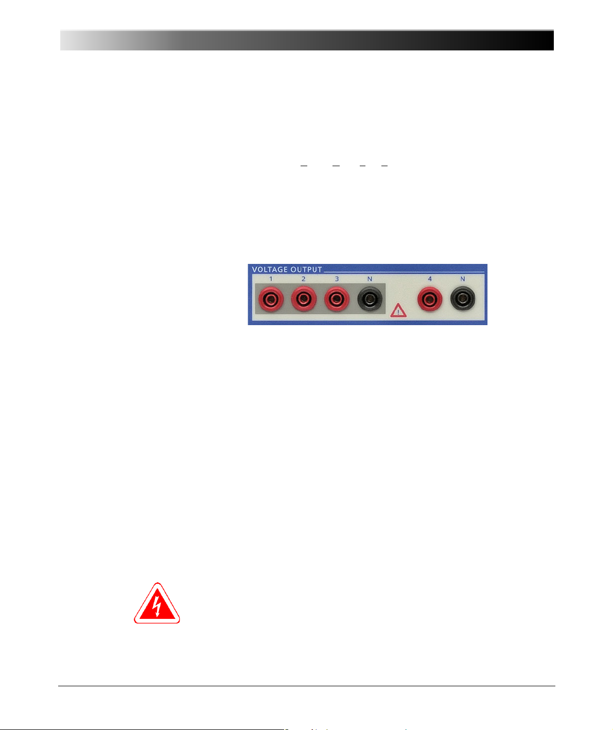
Figure 4-2:
Voltage amplifier
(voltage outputs)
The block schematic diagram in figure 4-1 shows all externally accessible
signals with gray shading. Every gray area represents a galvanic group that
is isolated from all of the other galvanic groups.
The power connection ("power supply group") and the connections for
“SELV group” (SELV = S
afety Extra Low Voltage) are available on the back
of the test set. All other gray shaded groups are available on the front of the
test set. The safety relevant isolated circuits (power ↔ SELV, power ↔ front
plate, and front plate ↔ SELV) are marked as "reinforced isolation" in the
block diagram.
4.1.1 Voltage Output (Voltage Amplifier)
Setup and Function
The four voltage outputs have a common neutral N and are galvanically
separated from all other outputs of the CMC 356. The two black sockets
labeled "N" are galvanically connected with one another.
The voltage amplifier and the current amplifiers are linear amplifiers with DC
coupling. The voltage outputs work in two ranges:
• Range 1: 4 x 0 ... 150 V
• Range 2: 4 x 0 ... 300 V
Protecting the Voltage Outputs
All voltage outputs are protected for open circuits, L-N short-circuits, and
overload. Should the heat sink overheat, a thermal switch turns off all
outputs.
Overload Warning Flagged in the Software
When a voltage output is overloaded, a corresponding warning is displayed
in the user interface of the test software of the OMICRON Tes t Uni ve rse
(like described in, for example, section 8.3, "Overheating" on page 103).
Do not connect any of the VOLTAGE OUTPUTS 1 ... 3 or VOLTAGE
OUTPUT 4, respectively, to protective earth. The N sockets, however, may
be connected to protective earth.
21
Page 22
CMC 356 Reference Manual
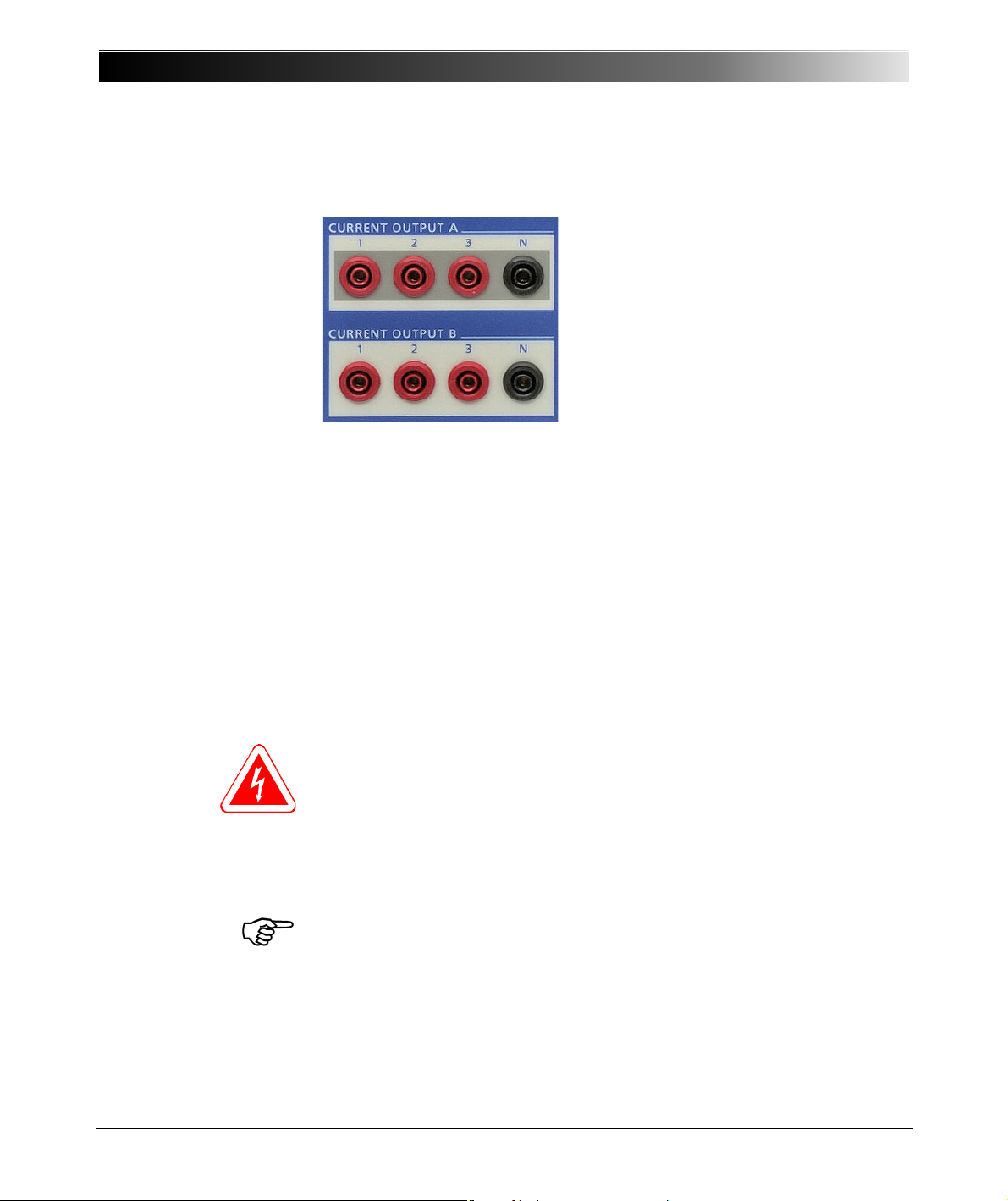
CURRENT OUTPUT A
CURRENT OUTPUT B
Two galvanically separated three-phase
current outputs, each with their own
neutral (N).
Each output is galvanically separated
from all other connections of the
CMC 356.
4.1.2 Current Output (Current Amplifier)
Figure 4-3:
CMC 356 current outputs
groups A & B
The current amplifiers are implemented as switched mode amplifiers with
DC coupling. With this technology it is possible to achieve high power
density in a very compact structure. The DC coupling enables a precise
reproduction of transients or DC offsets.
Protecting the Current Outputs
All current outputs are protected for open circuits, short-circuits, and
overload. If the heat sink overheats, a thermo switch turns off all outputs.
The output sockets are internally protected against currents > 45 A
(32A
; the CMC 356 switches off with the error message "current on
rms
neutral too high").
In non-operative state, relay contacts (as illustrated in figure 5-3) protect the
current amplifier from external power by shortening the outputs to N.
Caution: If there is an in-feed from an external source, the current outputs
can be damaged or destroyed.
Overload Warning Flagged in the Software
When a current output is overloaded, a corresponding warning is displayed
in the user interface of the test software of the OMICRON Test Universe
(like described in, for example, section 8.3, "Overheating" on page 103).
Please see also section 7.1, "Safety Instructions for High Current Output" on
page 91.
peak
22
Page 23
4.1.3 Binary / Analog Input (Binary Inputs 1 - 10)
Four binary outputs are available for use as
potential-free relay contacts.
More detailed information about the
configuration of the binary outputs can be
found in the OMICRON Test Universe
Help.
Figure 4-4:
Binary/analog inputs 1 - 10
Setup and Function
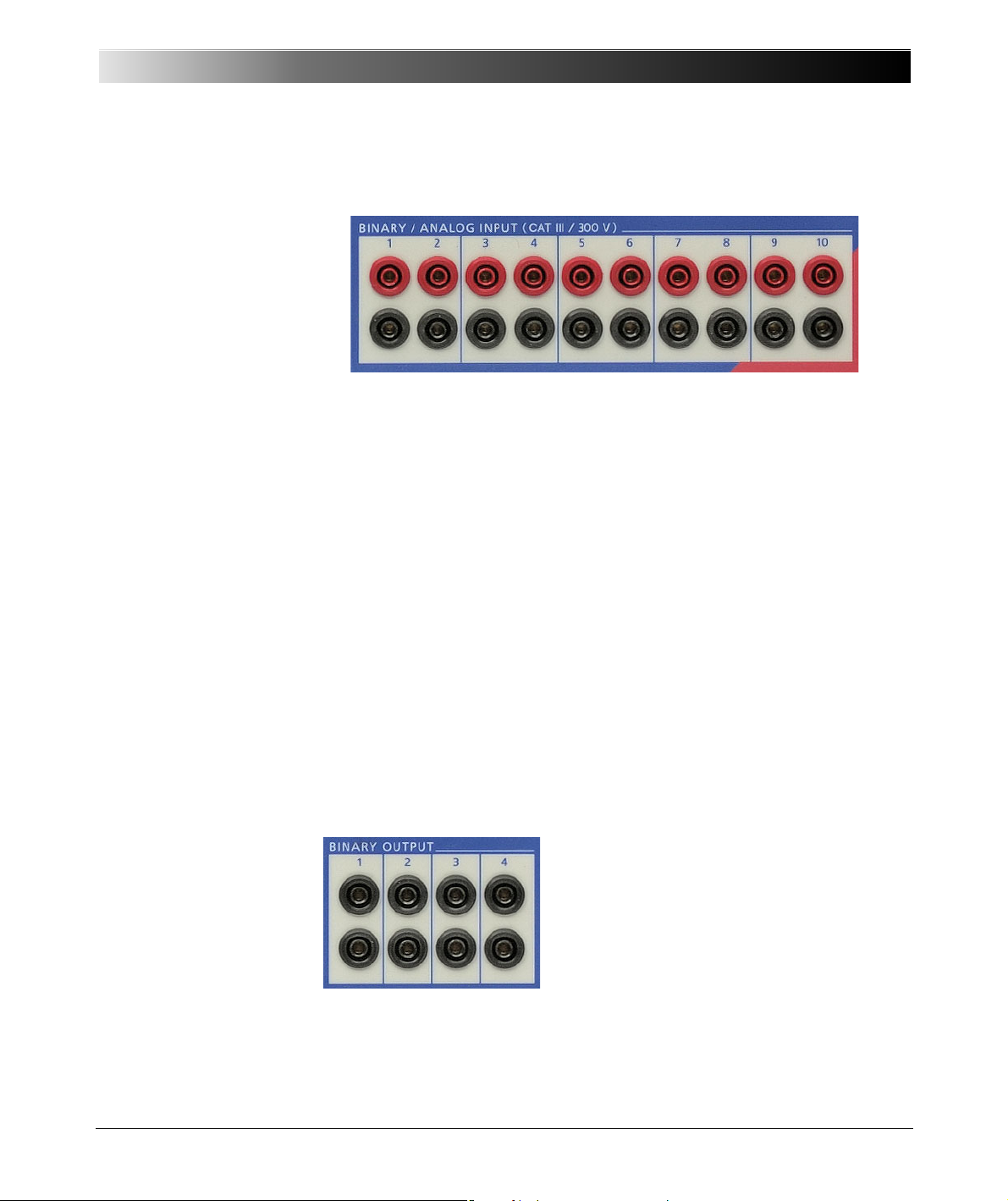
The ten binary inputs are divided into five groups of two, each group
galvanically separated from the others. If the hardware option ELT-1 is
installed, all inputs can be configured individually by the software as binary
or analog measurement inputs (refer to section 6.10, "Option ELT-1" on
page 67).
The input signals are monitored with a time resolution of 100 µs and then
evaluated in the CPU.
Figure 4-5:
Binary outputs
The binary inputs are configured from the Hardware Configuration module
of the OMICRON Tes t Un iv ers e software. When doing so, it can be specified
whether the contacts are potential-sensitive or not. When the contacts are
potential-sensitive, the expected nominal voltage and pick-up threshold can
be set for each binary input.
Moreover, the binary inputs 1 – 10 can be used as counter inputs for input
frequencies up to 3 kHz.
More detailed information about the configuration of the binary inputs can be
found in the OMICRON Test Universe Help.
4.1.4 Binary Output
23
Page 24
CMC 356 Reference Manual
4.1.5 AUX DC (DC Power for Test Objects)
Figure 4-6:
DC power for test objects
(AUX DC)
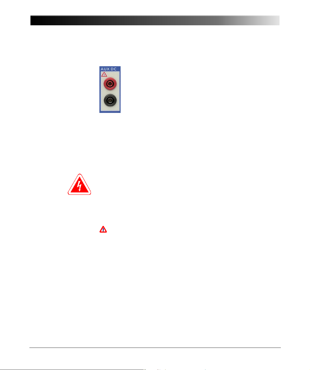
Test objects that require an auxiliary DC voltage can be fed from
the AUX DC output.
The DC voltage that is applied over the AUX DC output can vary
from 0 to 264 Volts and is configured using the software.
The AUX DC output is galvanically separated from all other
outputs.
The power-up default
By means of the test tool AuxDC you can set a so-called power-up default.
When the test set is powered-up the next time, the auxiliary DC output is
automatically set to this default value. This default value applies until it is
deliberately changed again.
Setting a power-up default value means, that immediately after the test set
is switched on, this voltage is applied to the auxiliary DC voltage output,
regardless whether a computer is connected to it or not.
Caution: The selected voltage can be life-threatening!
Consider storing a power-up default voltage of higher than 0 V a potential
danger to future users that may connect other devices to this CMC test set.
We strongly recommend to always set the default value to 0 V before storing
the device, or to otherwise attach a warning label to the device housing,
such as "This unit outputs an AuxDC voltage of ___V immediately after
powering-up".
If the voltage on the "AUX DC" output exceeds 42 V, the associated
signal light lights up.
More information about the configuration of the AUX DC supply can be
found in the OMICRON Test Universe AuxDC Help.
24
Page 25

4.1.6 CPU
The CMC 356 CPU (Central Processing Unit) carries out the following tasks:
• Communication with the computer or a network via the Ethernet ports
“ETH1” and “ETH2”.
• Digital signal generation for all outputs of the test set (including control
signals for external amplifiers).
• Generation of a high-accuracy central clock signal with synchronization
options using the CMGPS synchronization unit or the CMIRIG-B
interface box (refer to 9.3, "Time Synchronization Accessories" on page
107).
• Monitoring and control of all systems, including external amplifiers, if
applicable.
4.1.7 Power Supplies (DC-DC)
An AC/DC converter generates the required DC voltage from 85 to 264 VAC
supply voltage (see section 6.1) and ensures adequate EMC filtering.
Setup and Function
The power supply to the different modules, that each are part of their own
galvanic groups, are implemented using DC-DC converters with reinforced
insulation.
4.2 Signal Generation
The generation of sine wave signals with high amplitude and phase
accuracy is required in order to achieve output signals with the specified
accuracy.
In order to fulfill the requirement for phase-coupled signal sources, signal
generation is digitally implemented.
For this, the CMC 356 employs a high-performance digital signal processor
(DSP).
With digital signal generation the system is very flexible. An exact correction
of the amplitude, offset, and phase can be carried out in a digital manner
through the use of device-specific parameters (i.e., gain, offset, and null
phase angle on every channel).
The digital correction assures the best possible long-term drift behavior.
In addition to sine waves, any other periodic or transient signal can be
generated.
25
Page 26

CMC 356 Reference Manual
4.2.1 Accuracy and Signal Quality
The CMC 356 is a very precise test set with excellent long-term and
temperature drift behavior.
To achieve this accuracy, the philosophy was not only to solve signal
generation digitally, but also to implement the distribution of signals to the
various modules using digital methods. In doing so, the goal of galvanic
separation of the individual generator groups was also achieved without loss
of accuracy.
In achieving the amplitude accuracy, the drift behavior (temperature and
long-term) is of major importance in the voltage references, the digitalanalog converters (DAC), the accurate voltage dividers in the voltage
amplifiers, and the current shunts in the current amplifiers.
The actual (typical) data is in general about a factor of 3 better than the
guaranteed data.
The associated exact measurement media are required for the assurance of
the accuracy in the production. The measurement media used by
OMICRON are regularly calibrated by an accredited calibration institute so
that tracing to international standards can be assured.
26
Page 27
5CONNECTIONS AND INTERFACES
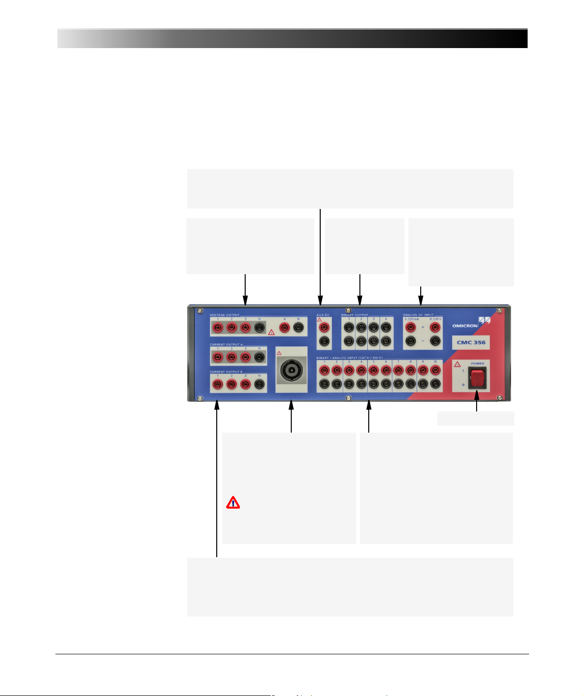
AUX DC
Output voltage in 3 ranges from 0 - 264 V; used to supply power to test objects.
VOLTAGE OUTPUT
4x300V
rms
output of the
internal voltage amplifier;
outputs 1 - 3 also applied to the
generator combination socket.
BINARY OUTPUT
Four potential-free
relay contacts.
ANALOG DC INPUT
(with option ELT-1 only)
0-±1mA / 0-±20mA:
DC current inputs.
0-±10V:
DC voltage inputs.
BINARY / ANALOG INPUT
10 binary inputs in 5 galvanically
separated groups.
Hardware option ELT-1:
The inputs can be configured as
analog measurement inputs. Without
option ELT-1 only binary inputs are
available.
CURRENT OUTPUT
Group A: 3x32A
rms
output of the internal current amplifier; also applied to the
generator combination socket.
Group B: 3x32A
rms
output of the internal current amplifier.
Generator combination socket
8-pole combination socket for
VOLTAGE OUTPUT 1-3 and
CURRENT OUTPUT A (up to
3 × 25 A max.).
Warning indication:
Dangerous Voltage!
At least one of the output
voltages exceeds 42 V.
Power Switch
5.1 Front Panel Connections
Figure 5-1:
Front view of the CMC 356
Connections and Interfaces
27
Page 28
CMC 356 Reference Manual
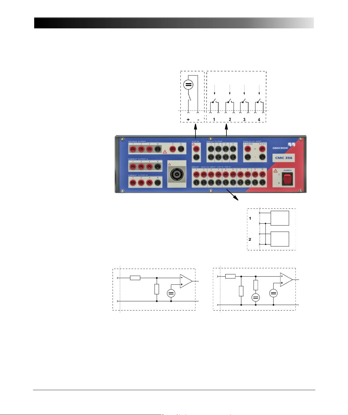
BINARY OUTPUT
Software controlled
BINARY/ANALOG INPUT
3 - 10 identical
Circuit diagram of a binary input for
potential-free operation (dry)
132 kΩ
V
th
< 20 V: 78 kΩ
Vth > 20 V: 3.2 kΩ
V
th
132 kΩ
V
th
350 kΩ
110 kΩ
11 V
Circuit diagram of a binary input with
programmable threshold voltage
(wet operation)
Each binary input can be configured individually
for wet or dry operation.
Two inputs (1 + 2, 3 + 4, ...) are one potential
group. The inputs grouped in one potential group
share a common ground.
AUX DC
Note: For simplified circuit diagrams of the inputs BINARY/ANALOG INPUTS and
ANALOG DC INPUT of the CMC 356 with hardware option ELT-1 installed, please
refer to Figure 6-20 on page 72.
Figure 5-2:
Simplified circuit diagrams
of binary inputs and
outputs (
CMC 356
standard, without option
ELT-1 installed)
28
Page 29
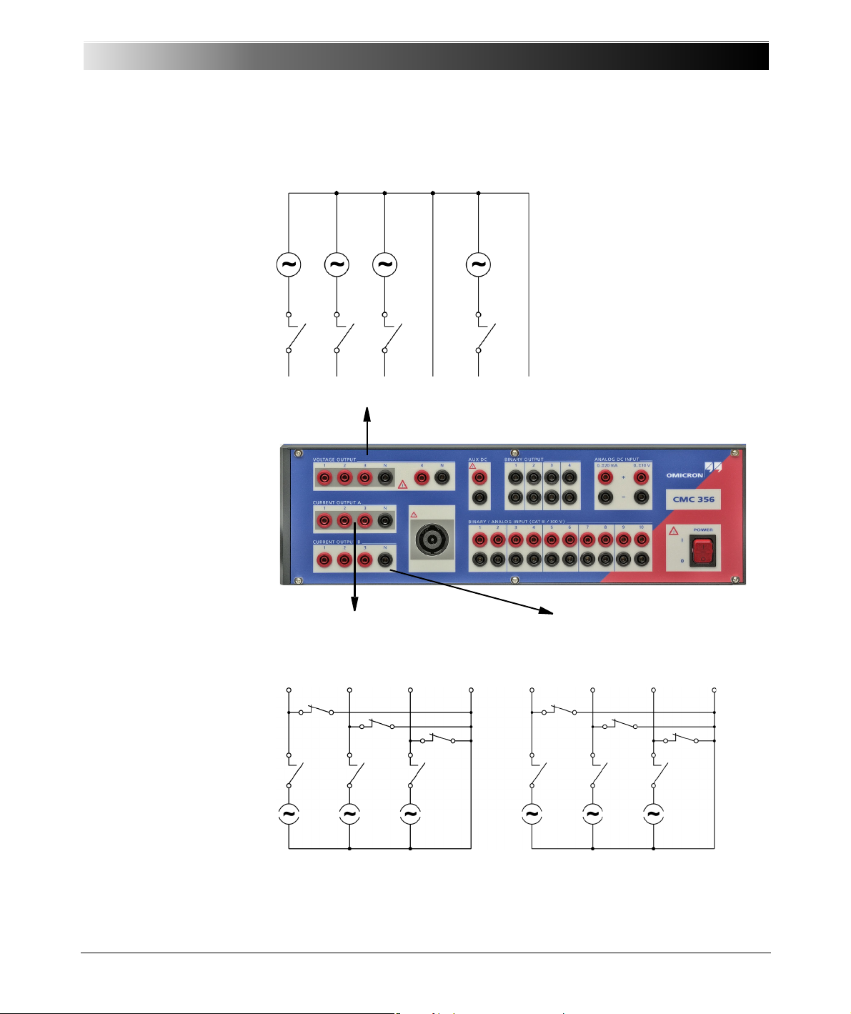
Figure 5-3:
VOLTAGE OUTPUT
4x300V
rms
CURRENT OUTPUT A
3x32A
rms
CURRENT OUTPUT B
3x32A
rms
123N4 N
123N
123N
Simplified diagrams of
current and voltage
outputs
Connections and Interfaces
In non-operative state, relay contacts (as illustrated in figure 5-3) protect the
current amplifier from external power by shortening the outputs to N.
29
Page 30
CMC 356 Reference Manual
Front view
View onto the connector from
the cable wiring side
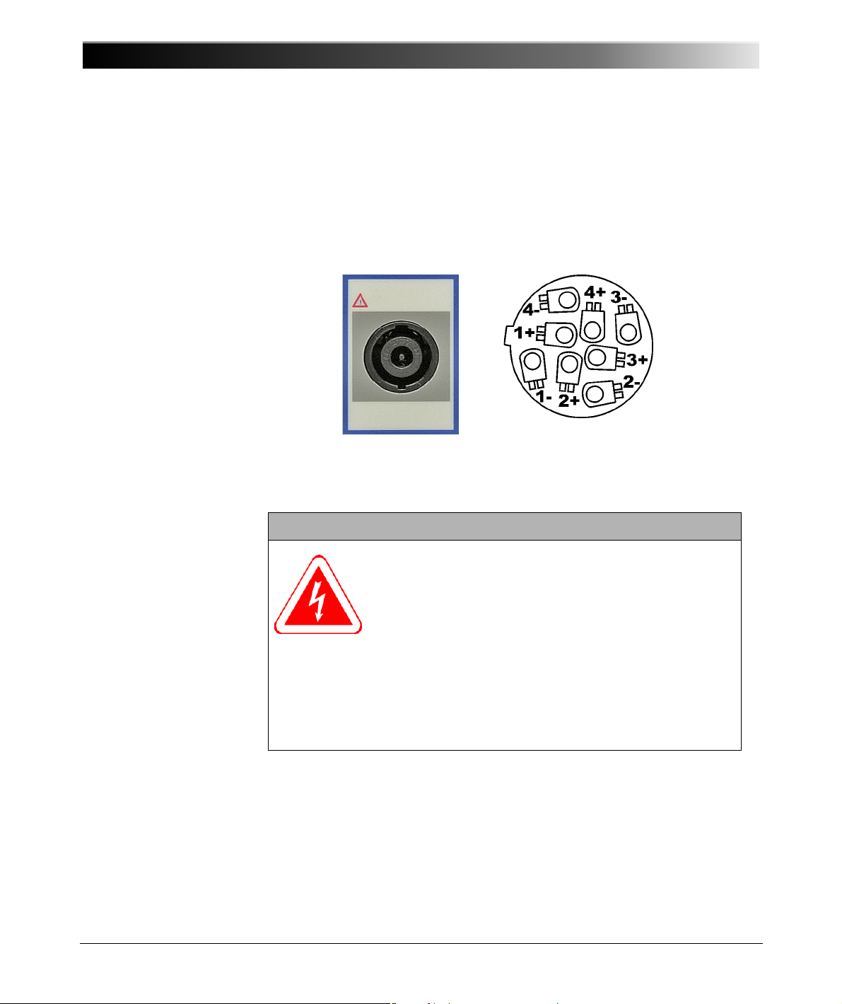
5.1.1 Generator Combination Socket for VOLTAGE OUTPUT and
Figure 5-4:
Generator combination
socket
CURRENT OUTPUT
The combination socket CURRENT OUTPUT / VOLTAGE OUTPUT
simplifies the connection of test objects to the CMC 356. The three voltage
outputs (VOLTAGE OUTPUT 1-3) as well as the CURRENT OUTPUT A are
wired to the combination socket (refer to table 5-1 on page 31).
WARNING:
The connections on the socket are dangerous when the
test set is turned on.
Follow the safety information provided at the beginning of
this manual when connecting the generator combination
sockets.
If a dangerous voltage (greater than 42 V) is applied to the socket, a
warning indicator lights above the socket.
For currents greater than 25 A, the test object (load) should be exclusively
connected to the 4 mm/0.16 " banana sockets and not on the generator
connection socket.
30
Page 31
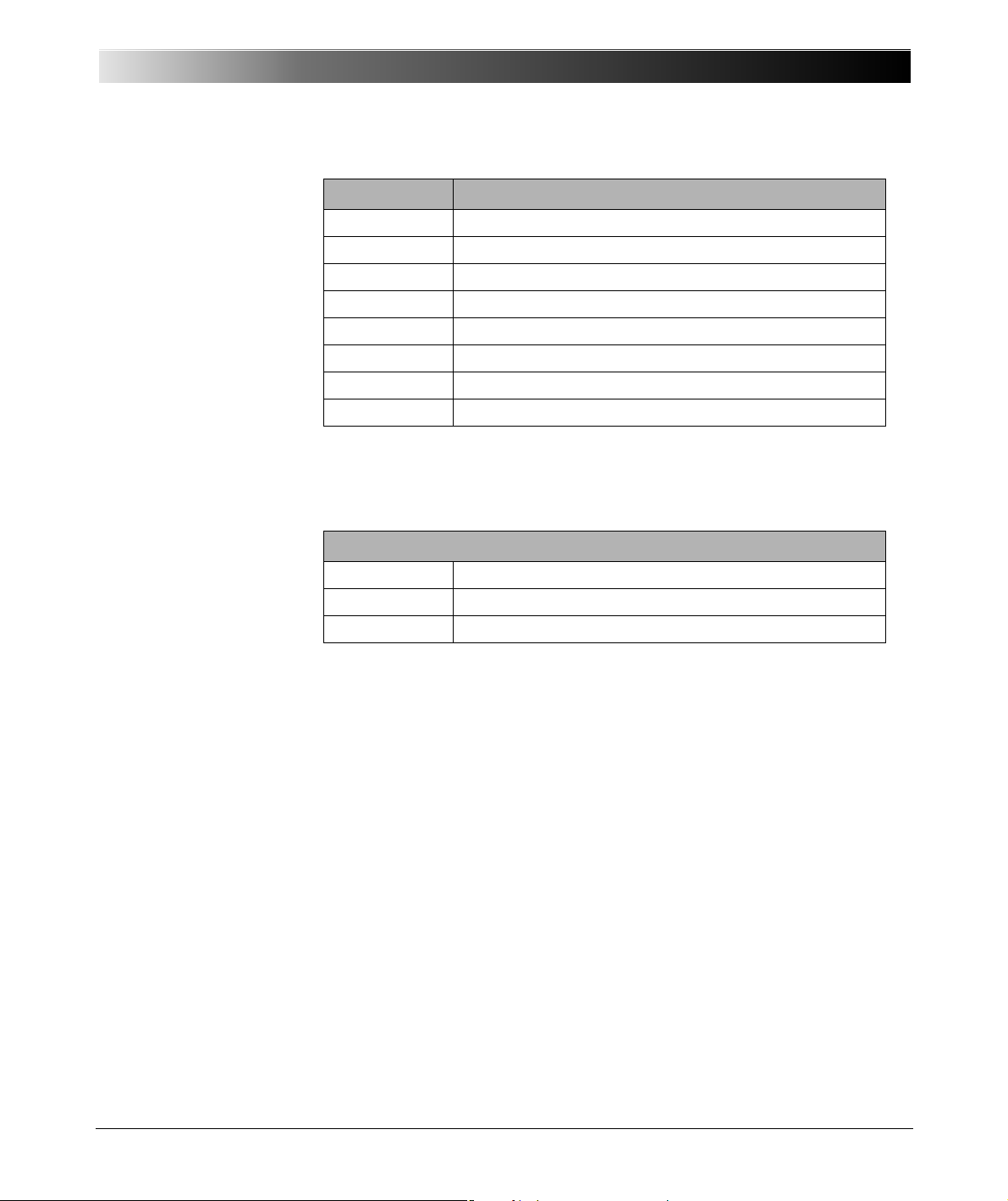
Table 5-1:
Pin layout
Table 5-2:
Manufacturer ordering
information
Connections and Interfaces
Pin Signal
1- VOLTAGE N
2- VOLTAGE 3
3- VOLTAGE 2
4- VOLTAGE 1
1+ CURRENT A 1
2+ CURRENT A N
3+ CURRENT A 3
4+ CURRENT A 2
Note: If using negative sequence phase rotation, swap the connectors
VOLTAGE 2 and VOLTAGE 3 as well as CURRENT 2 and CURRENT 3.
Description of the generator combination socket
Description SPEAKON LINE 8-pole
Article Number NL8FC
Manufacturer Neutrik (www.neutrik.com)
You can order the plug for generator combination socket directly from
OMICRON. For the part number refer to section 9.8, "Ordering Information"
on page 127.
31
Page 32
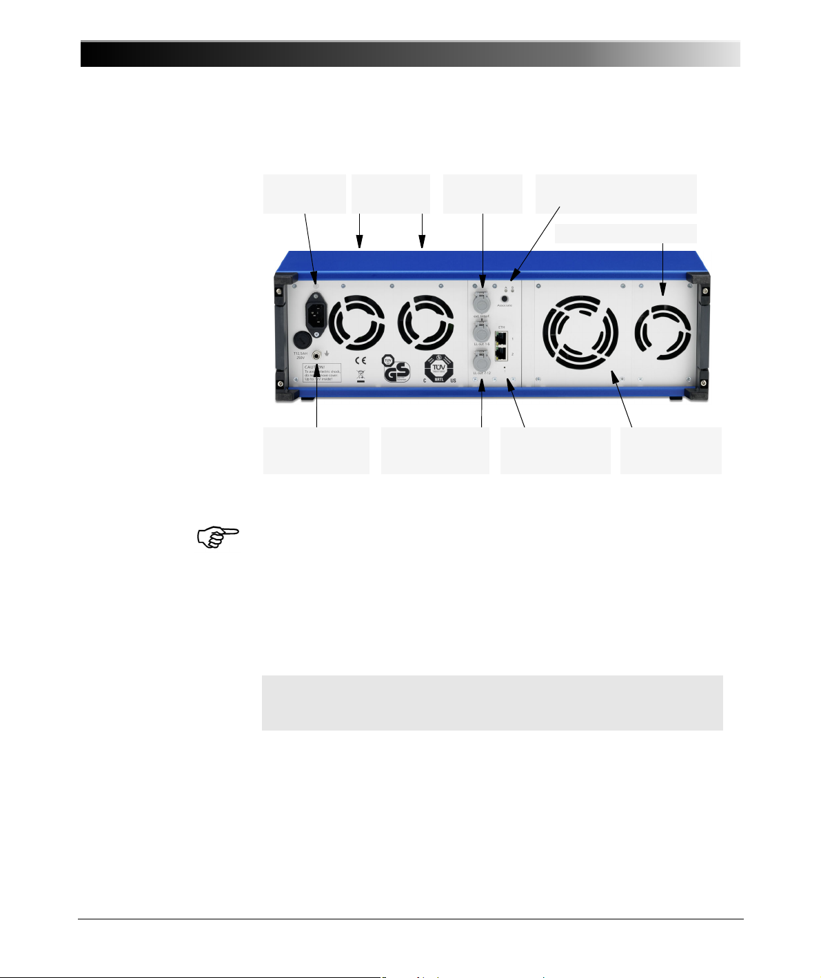
CMC 356 Reference Manual
Status LEDs A & B
"Associate" button
*) For example to connect to low resistance grounding bars.
Fans
power supply
Power supply
Fuse T12.5 AH
Interface
"ext. Interf."
4 mm/0.16 " socket
for additional
PE connection
*)
SELV interfaces
“LL out 1 - 6” and
“LL out 7 - 12”
Ethernet ports
ETH1 & ETH2
and "!" button
Fan voltage outputs
Fan
current outputs
5.2 Connections on the Back Panel
Figure 5-5:
Rear view of
CMC 356
The SELV interface LL out 7 - 12 is optional. Please refer to section 6.11,
"Option LLO-2 (Low Level Outputs)" on page 90.
5.2.1 Ethernet Ports ETH1 and ETH2
The two PoE (Power over Ethernet) ports ETH1 and ETH2 are standard
32
10/100Base-TX (twisted pair) Ethernet ports. They support auto crossing
(auto MDI/MDIX). This means you can use a standard cable or a cross-over
Ethernet patch cable.
Note: If your Ethernet ports ETH1 and ETH2 look different, i.e., ETH2 is
the connector version of Fast Ethernet over optical fiber, refer to chapter
6.5, "Technical Data of the Ethernet Ports" on page 63.
Since the CMC test set can be controlled over a network, any distance
between the controlling computer and the test set is possible. This enables
direct remote control of the CMC test set, e.g., for end-to-end testing.
The Ethernet ports also provide the basis for the processing of substation
protocols according to the IEC 61850 standard. They allow flexible
configurations, e.g., for separation of data traffic from different network
segments or segregation of substation protocol data and test set control
commands.
Page 33
The green LED indicates a link connection to a PC or a network. The yellow
!
Associate
LED indicates active traffic (receiving or transmitting) on the cable.
For detailed technical data about the Ethernet ports, please refer to section
6.5, "Technical Data of the Ethernet Ports" on page 63.
5.2.2 ! Button
The ! button enables you to recover from unsuccessful software image
downloads or other emergency situations. To start a new software image
download, press the ! button with a pointed tool or a paper clip while
powering-up the CMC. In that case, the test set will not start as usual but
wait for a new software image download.
5.2.3 Associate Button
The Associate button has the following functions:
• Association with controlling computer
An Ethernet communication port enables you to communicate with any
CMC available on the network. This may lead to dangerous situations
where a user accidentally connects to a device located on a desk of
somebody else, emitting unsafe voltages and endangering the person
working there.
To prevent such a situation, a special mechanism is integrated into the
CMC test set that allows only “authorized” clients to control the test set.
By using the Associate button, the test set is registered for use with a
specific host computer.
The test set will issue voltages and currents only when it is associated to
the client requesting this. The association process can be initiated by the
Test Set Association and Configuration tool or by the OMICRON
Device Browser. For more details about this process, refer to the Help of
the according tool.
Connections and Interfaces
For the association the Ethernet hardware address (MAC) of the
controlling computer is remembered. Consequently, if the network
interface on the computer has changed, the CMC test set has to be
associated whenever the MAC address changes.
• Reset IP Configuration
If the Associate button is pressed while powering up the CMC test set,
the IP configuration of the network interfaces is reset to factory default,
which is DHCP/AutoIP for both network interfaces. It may be necessary
to reset the IP configuration in this way to recover from settings with
conflicting static IP addresses.
33
Page 34

CMC 356 Reference Manual
5.2.4 Status LED A, B
The status LED A and B are of interest in case of troubleshooting.
A: yellow status LED
• A lit yellow LED indicates that the test set is ready to be controlled by a
computer. The hardware checks in the test set are finished, and the test
set is properly connected to a computer or a network.
• The LED is off when the test set is waiting for an "emergency software
image download". This is the case when pressing the ! button while
powering-up the CMC test set.
B: green LED
If the yellow LED A is off, the green LED B signals the following conditions:
• LED B blinks slowly:
CMC test set waits for the TFTP download (Trivial File Transfer Protocol)
of a software image.
• LED B is lit:
The TFTP download of the software image is in progress.
• LED B blinks quickly:
The computer writes (e.g., the software image) to the flash memory of
the CMC test set. Do not turn off the CMC test set as long as the writing
is in progress.
5.2.5 Ethernet / Network Settings
General
The OMICRON Test Universe software running on the computer
communicates with the CMC test set via a network connection. Therefore it
is possible to either have the CMC directly connected to the computer’s
network plug by a cable or to have the CMCand the controlling computer
connected to a computer network.
Both network ports can be used equally, and both network ports have link
LEDs (green) and traffic LEDs (yellow flashing) to check the physical
connectivity and proper cabling.
IP Configuration
For the CMC test set to communicate with the controlling computer and the
OMICRON Test Universe software, TCP/IP is used. The IP parameters are
set by either the Test Set Association and Configuration tool or the
OMICRON Device Browser.
34
Page 35
Connections and Interfaces
The CMC test set can either be set to static IP addresses or use DHCP
(Dynamic Host Configuration Protocol) and AutoIP/APIPA (Automatic
Private IP Addressing).
Additionally, there is a special DHCP server integrated in the CMC test set
to serve IP addresses only for that computer the OMICRON Test Universe
software is running on. Note that this will only take place when there is no
DHCP server in the network. If there is DHCP server in the network, the
DHCP feature of the CMC test set remains inactive.
If the IP settings conflict with IP settings of other devices in the network, it is
possible to reset the test set to factory defaults (DHCP and AutoIP) by
pressing the Associate button at the rear of the test set while powering up
the test set.
Security / Firewall Settings
To automatically detect and set the IP configuration of CMC test sets in the
network, IP-multicasting is used by the Test Universe software. Therefore, a
firewall program has to be configured to allow for this communication. For
the Microsoft Windows Firewall in Windows XP SP2 (or later) the
configuration of the firewall is done automatically during installation of the
OMICRON Test Universe.
The software component on the computer that automatically detects test
sets on the network (OMFind.exe) requires an enabled inbound connection
on port 4987 for UDP. For TCP communication, the software component on
the computer that controls the test sets (CMEngAl.exe) requires an enabled
outbound connection on port 2200.
More information about the Firewall configuration can be found in the FAQ
section of the Get Support booklet (Technical Support for CMC Test Sets).
This manual is available as PDF file on your hard disk after the installation of
OMICRON Test Universe. Its name is _Support Booklet.pdf.
Network Troubleshooting
For instructions to help you to incorporate network-capable CMC test sets
into a computer network, please refer to the manual Network-based CMC
Test Sets. This manual is available as PDF file on your hard disk after the
installation of OMICRON Test Universe. Its name is Network-based test
sets.pdf.
To view the manuals, start the Test Universe Help from the Start Page or any
test module and navigate to the table of contents entry User Manuals (at the
beginning of the table of contents). Click Read Me First. In this topic you find
direct links to both manuals. To open a manual, just click the link.
35
Page 36

CMC 356 Reference Manual
ext. Interf.
5.2.6 SELV Interfaces
5.2.6.1 External Interface ("ext. Interf.")
All inputs and outputs to the SELV group (SELV = Safety Extra Low Voltage)
reference to a common neutral that is internally connected to the protective
earth (GND) of the housing.
The SELV interface connector "ext. Interf." holds four additional transistor
binary outputs (Bin. out 11 - 14). Unlike regular relay outputs,
Bin. out 11 - 14 are bounce-free binary outputs (small signals) and have a
minimal reaction time.
In addition, two high frequency counter inputs for up to 100 kHz are
available for the testing of energy meters.
For more detailed information please refer to the technical data section
6.3.6, "Low-Level Binary Outputs ("ext. Interf.")" on page 54.
Meter Testing
For energy meter test applications, the "ext. Interf." permits easy
connectivity. For more information about the connection of scanning heads
please refer to sections 9.6.5, "Adapter Cable for Scanning Heads" on page
117 and 9.6.6, "CMLIB B" on page 118.
Synchronization
Via the "ext. Interf.", the CMC 356 time base can be GPS- and IRIG-Bsynchronized. Depending on the synchronization method of your choice,
use either the CMGPS synchronization unit or the CMIRIG-B interface box.
Both synchronization accessories, the CMGPS and the CMIRIG-B, are
optional and are described in more details in section 9.3, "Time
Synchronization Accessories" on page 107.
36
Page 37
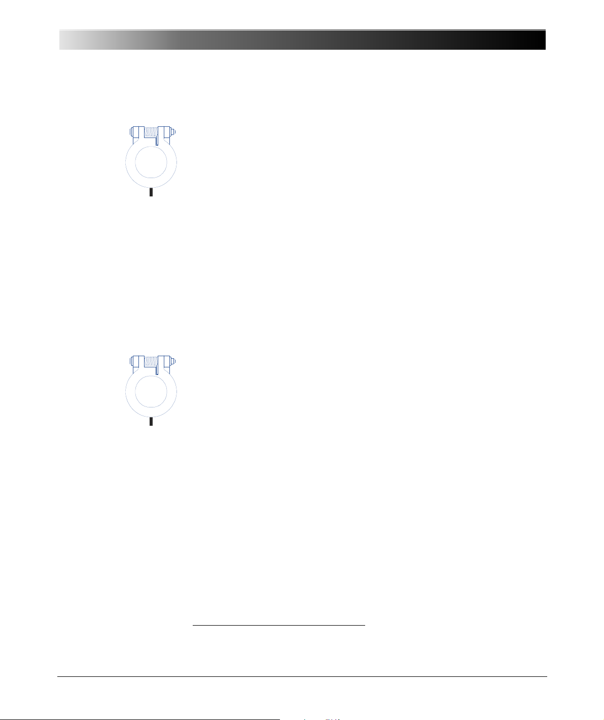
5.2.6.2 LL out 1-6 (Low Level Outputs 1-6)
LL out 1 - 6
LL out 7 - 12
The SELV interface connector "LL out 1 - 6" holds two independent
generator triples. These six high accuracy analog signal sources can serve
to either control an external amplifier or to directly provide small signal
outputs.
In addition, a serial digital interface is available that transmits control and
monitor functions between the CMC 356 and the external amplifiers.
Supported devices are CMA 156, CMA 56
CMS 252.
The low level outputs are short-circuit-proof and continually monitored for
overload.
Connect the external amplifier to the CMC 356 low level outputs. Use the
connecting cable that was supplied with the amplifier.
For more detailed information please refer to the technical data section
6.3.5, "Low Level Outputs "LL out" for External Amplifiers" on page 52.
Connections and Interfaces
1
, CMS 156, CMS 2511 and
5.2.6.3 LL out 7-12 (Low Level Outputs 7-12) - Option "LLO-2"
The SELV interface connector "LL out 7 - 12" is an option available for the
CMC 356 test set.
The outputs 7-12 extend the low level outputs 1-6 by two more independent
generator triples. Outputs 7-12 are technically identical to outputs 1-6 as
described above.
For more detailed information please refer to the technical data section 6.11,
"Option LLO-2 (Low Level Outputs)" on page 90.
Overload Warning Flagged in the Software
When a low level output is overloaded, a corresponding warning message
appears on the user interface of the OMICRON Test Universe software.
1
These products are not available anymore.
37
Page 38

CMC 356 Reference Manual
38
Page 39
6TECHNICAL DATA
Guaranteed Values:
• General:
The values are valid for the period of one year after factory calibration,
within 23 °C ± 5 °C at nominal value and after a warm-up time greater
than 25 min.
• Guaranteed values from the generator outputs:
The values are valid in the frequency range from 10 to 100 Hz unless
specified otherwise. Given maximum phase errors are related to the
voltage amplifier outputs.
• Accuracy data for analog outputs are valid in the frequency range from
0 to 100 Hz unless specified otherwise.
• The given input/output accuracy values relate to the range limit value
(% of range limit value).
Technical Data
Table 6-1:
Power supply data
6.1 Main Power Supply
Main Power Supply
Connection Connector according to IEC 60320
Voltage, single phase
nominal voltage
operational range
Power fuse T 12.5 AH 250 V (5 x 20 mm)
Nominal current
Frequency
nominal frequency
operational range
Overvoltage category II
1
Refer to section 6.3.4, "Operational Limits in Conjunction with Mains Supply" on page 51.
1
100-240V
85 ... 264 V
AC
AC
"Schurter", order number 0001.2515
at < 170 V: 12 A max.
at > 170 V: 10 A max.
50/60 Hz
45 ... 65 Hz
39
Page 40
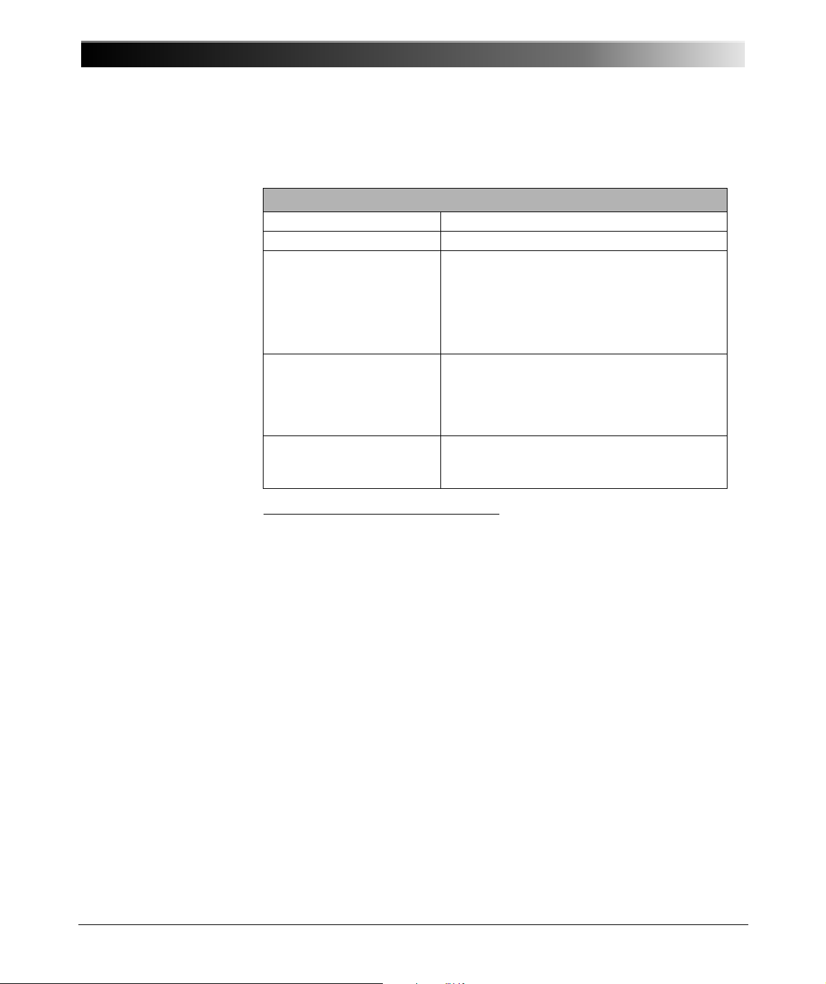
CMC 356 Reference Manual
6.2 Insulation Coordination
Table 6-2:
Insulation coordination
Insulation Coordination
Overvoltage category II
Pollution degree 2 (except for Binary Inputs)
Insulation of function
groups on front panel to
ground (GND)
1
- Basic insulation with maximum voltage of
600 V
to ground
rms
- Clearance: > 3 mm (0.12 ")
- Creepage: > 6 mm (0.24 ")
Insulation of functional
groups on front panel from
each other
- Test voltage: 2200 V
- Working insulation
- Clearance: > 1 mm (0.04 ")
- Creepage: > 1 mm (0.04 ")
rms
- Test voltage: 1500 VDC
Measurement category
(BINARY / ANALOG
INPUTS)
- CAT III / 300 V
- CAT IV / 150 V
rms
rms
1
Functional groups on CMC 356 front panel:
VOLTAGE OUTPUT, CURRENT OUTPUT (A, B), AUX DC, BINARY OUTPUT,
BINARY / ANALOG INPUT, ANALOG DC INPUT
40
Page 41
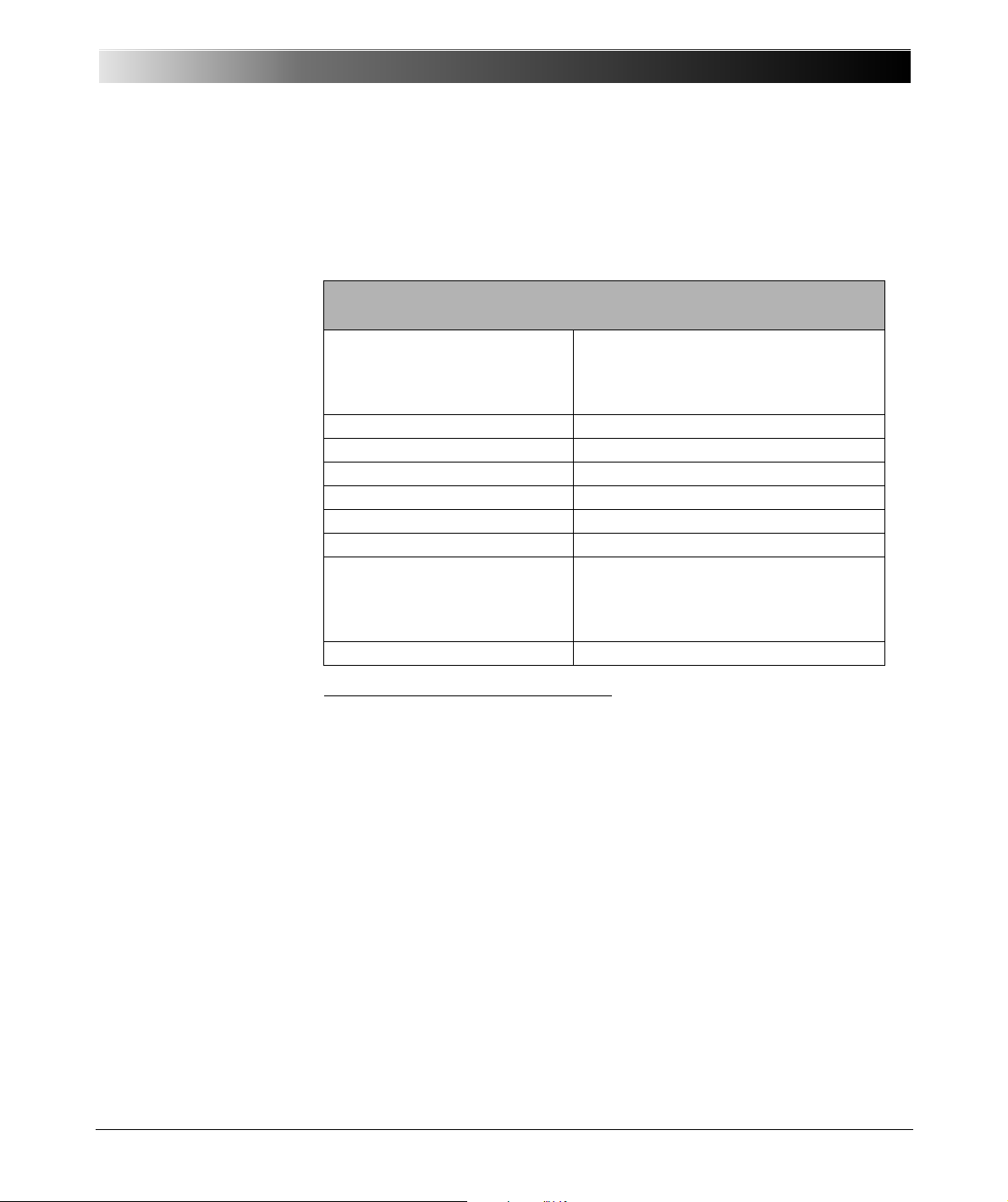
6.3 Outputs
Table 6-3:
Analog current, voltage,
and LL outputs.
Technical Data
For block diagrams of the available generator outputs, please refer to
section 4.1, "Block Diagram" on page 20.
General Generator Outputs Data
(analog current and voltage outputs, outputs "LL out")
Frequency ranges
sinusoidal signals
harmonics / interharmonics
transient signals
1
2
10 … 1000 Hz
3
10 … 3000 Hz
DC … 3.1 kHz
Frequency resolution < 5 µHz
Frequency accuracy ± 0.5 ppm
Frequency drift ± 1 ppm
Bandwidth (–3 dB) 3.1 kHz
Phase range ϕ - 360° to + 360°
Phase resolution 0.001°
Synchronized operation Generator outputs can be synchronized
to a reference input signal on
binary/analog input 10 (range:
40 … 70 Hz).
Temperature drift 0.0025 %/°C
1
If you purchased the option FL-6, the maximum output frequency is constrained to 599 Hz.
2
Amplitude derating for current outputs at frequencies above 380 Hz.
3
Signals above 1 kHz are only supported in selected Test Universe modules and are only
available on the voltage outputs and the low level outputs.
All voltages and current generators can independently be configured with
respect to amplitude, phase angle, and frequency.
All outputs are monitored. Overload conditions result in a message
displayed on the PC.
41
Page 42
CMC 356 Reference Manual
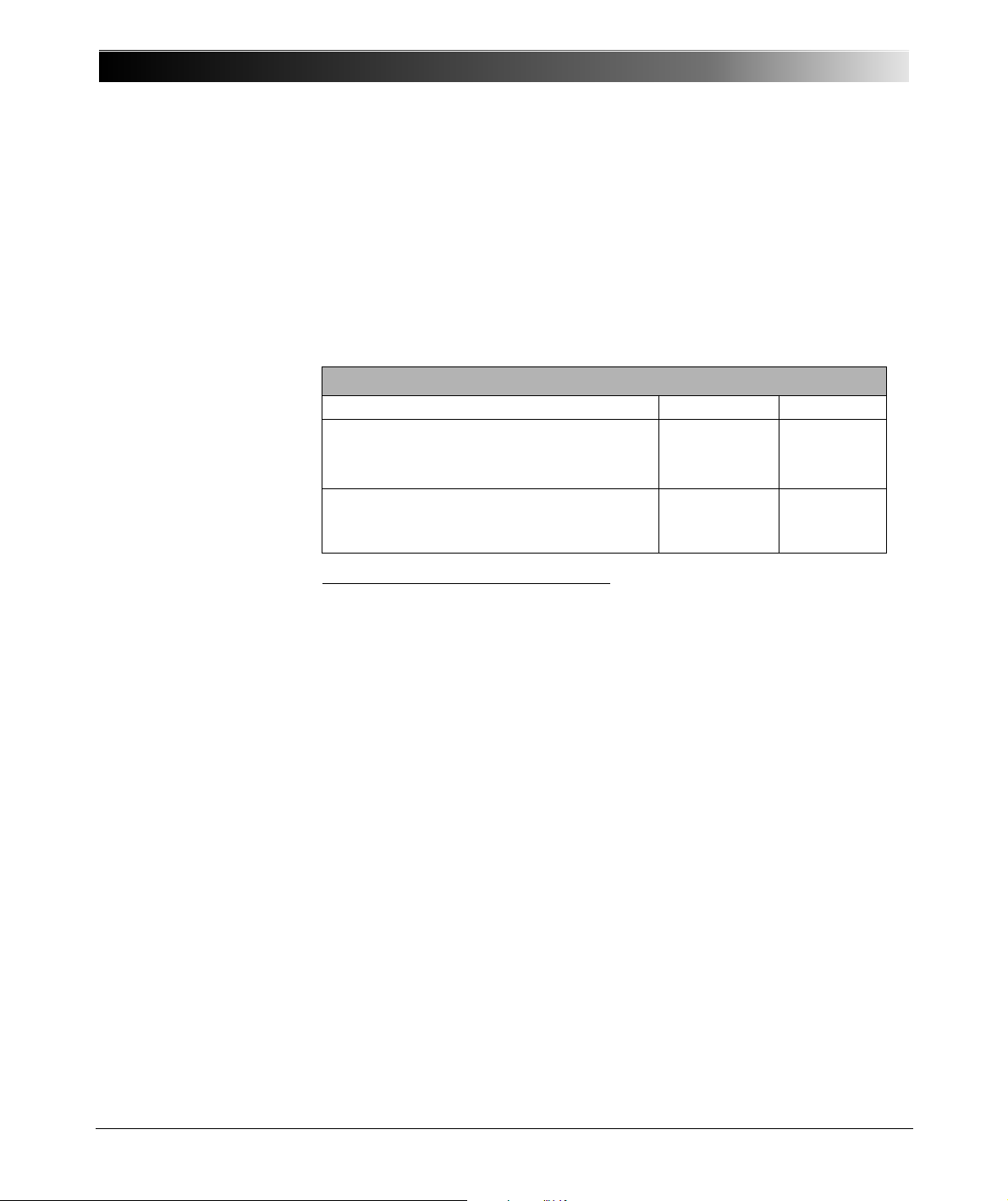
6.3.1 Extended Frequency Range
Table 6-4:
Extended frequency range
(1 - 3 kHz)
In selected Test Universe modules (e.g., Harmonics and PQ Signal
Generator) the CMC 356 supports a mode for generating stationary signals
up to 3 kHz on the voltage outputs and the low-level outputs. This mode
corrects the phase and gain errors of the output filter. The 3 dB bandwidth of
this filter limits the amplitude at 3 kHz to about 70 % of the maximum range
value. The application of the extended frequency range is the generation of
harmonics and interharmonics.
Extended Frequency Range (1 - 3 kHz)
Typical Guaranteed
Low Level Outputs
Phase error
Amplitude error
1
< 0.25 °
< 0.25 %
< 1 °
< 1 %
Voltage Amplifier
Phase error
Amplitude error
< 0.25 °
< 0.25 %
< 1 °
< 1 %
1
No extended frequency range support for external amplifiers.
42
Page 43
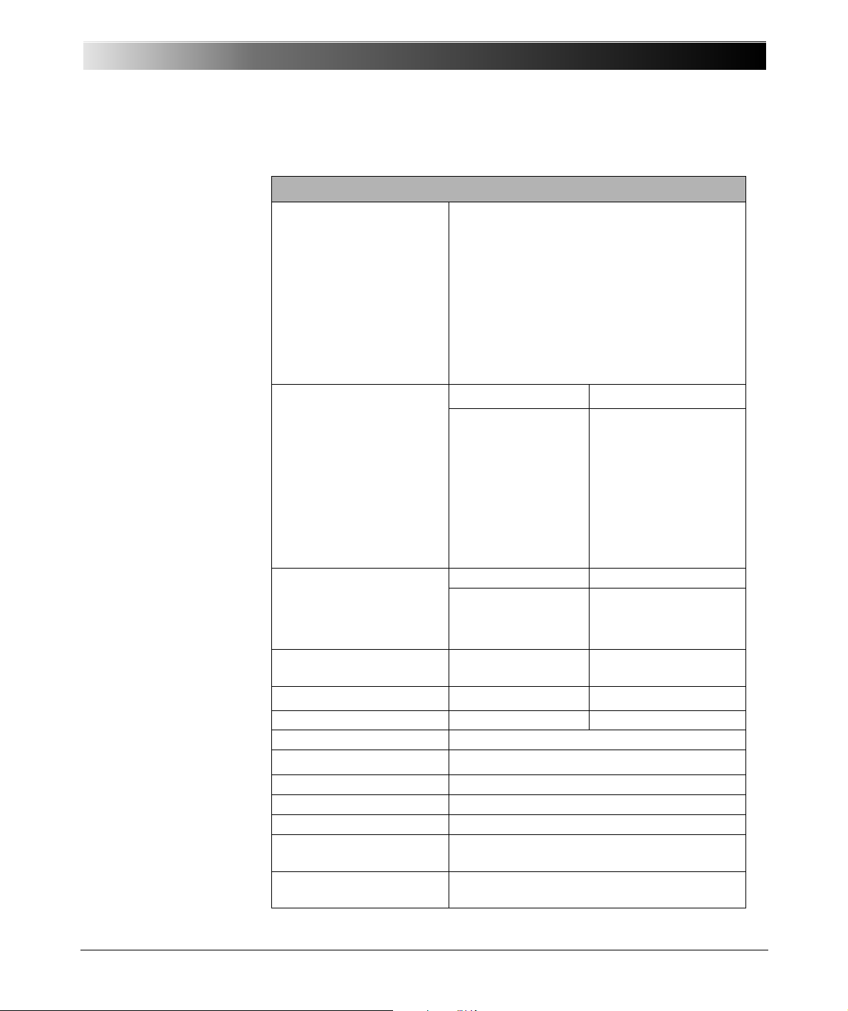
6.3.2 Current Outputs
Table 6-5:
Outputs of current groups
AandB
Footnotes:
1.Data for three-phase
systems are valid for
symmetric conditions
(0 °, 120 °, 240 °) unless
specified otherwise.
2. For wiring of single-
phase modes see
chapter 7, "Increasing
the Output Power,
Operating Modes" on
page 91.
3.Single-phase mode
(in phase opposition).
4.rd. = reading;
rg. = range, whereat
n % of rg. means: n % of
upper range value.
5.Valid for sinusoidal
signals at 50/60 Hz and
R
≤ 0.5 Ω.
load
6.Values at 20 kHz
measurement
bandwidth, nominal
value, and nominal load.
7.Guaranteed data at
230 V mains for ohmic
loads (PF=1); typical
data for inductive loads.
Refer to section 6.3.4,
"Operational Limits in
Conjunction with Mains
Supply" on page 51.
8.For currents > 25 A, connect test object only to
the 4 mm/0.16 " banana
connections and not to
the generator combination socket.
9.Current amplitude
derating at frequencies
above 380 Hz (see
Figure 6-4).
Technical Data
Current Outputs1 (Groups A and B)
Output currents
6-phase AC (L-N) 6 x 0 ... 32 A (Group A and B)
3-phase AC (L-N) 3 x 0 ... 64 A (Group A + B parallel)
2-phase AC (L-L)
1-phase AC (L-L)
1-phase AC (L-L-L-L)
2-phase AC (LL-LN)
1-phase AC (LL-LN)
DC (LL-LN)
7
Power
2, 3
2, 3
2
2 x 0 ... 32 A (Group A and B)
1 x 0 ... 64 A (Group A + B parallel)
2, 3
1 x 0 ... 32 A (Group A + B in series)
2
2 x 0 ... 64 A (Group A and B)
2
1 x 0 ... 128 A (Group A + B parallel)
1 x 0 ... ±180 A (Group A + B parallel)
Typical Guaranteed
6-phase AC (L-N) 6 x 430 VA at 25 A 6 x 250 W at 20 A
3-phase AC (L-N) 3 x 860 VA at 50 A 3 x 500 W at 40 A
2-phase AC (L-L)
1-phase AC (L-L)
1-phase AC (L-L-L-L)
2-phase AC (LL-LN)
1-phase AC (LL-LN)
DC (LL-LN)
2, 3
2, 3
2
2 x 870 VA at 25 A 2 x 550 W at 20 A
1 x 1740 VA at 50 A 1 x 1100 W at 40 A
2, 3
1 x 1740 VA at 25 A 1 x 1100 W at 20 A
2
2 x 500 VA at 40 A 2 x 350 W at 40 A
2
1 x 1000 VA at 80 A 1 x 700 W at 80 A
1x 1400W at ±80A 1x1000W at ±80A
Accuracy Typical Guaranteed
4
R
≤ 0.5 Ω
load
R
> 0.5 Ω Error < 0.1 % of rg. Error < 0.3 % of rg.
load
Harmonic distortion
(THD+N)
Phase error
5,6
5
Error < 0.05 % rd.
+ 0.02% of rg.
0.05 % < 0.15 %
0.05 ° < 0.2 °
Error < 0.15 % of rd.
+ 0.05% of rg.
DC offset current < 3 mA < 10 mA
Resolution 1
Frequency range
9
m
A, 2 mA (2 phases parallel), ...
0 … 1000 Hz
Trigger on overload Timer accuracy error < 1 ms
Short-circuit protection Unlimited
Open-circuit protection Open outputs (open-circuit) permitted
Connection 4 mm/0.16 " banana connectors, amplifier
connection socket
8
(OUTPUT A only)
Insulation Reinforced insulation of power supply and all
SELV interfaces
43
Page 44

CMC 356 Reference Manual
0
100
200
300
400
500
600
700
800
900
1000
0 102030405060
Output Current [Arms]
Output Power per Phase [VA] / [W]
S 6~ per phase [VA]
P 6~ per phase [W]
S 3~ (A// B) per phase [VA]
P 3~ (A// B) per phase [W]
P 3~ (one triple) per phase [W]
Output current in A
rms
Output power per phase in VA / W
per phase in VA
per phase in W
(A//B) phase in VA
(A//B) phase in W
(one triple) per phase in W
0
200
400
600
800
1000
1200
1400
1600
1800
2000
0 102030 405060708090100
Output Current [Arms]
Output Power [VA] / [W]
S: 32A (L-L-L-L) [VA]
P: 32A (L-L-L-L) [W]
S: 64A (L-L) [VA]
P: 64A (L-L) [W ]
S: 128A (LL- LN) [VA]
P: 128A (LL- LN) [W]
Output current in A
rms
Output power in VA / W
Figure 6-1:
Guaranteed output power
per phase of a group and
when groups A and B are
connected in parallel
(active power values in W
are guaranteed; apparent
power values in VA are
typical values)
Figure 6-2:
Guaranteed single phase
output power curves
(active power values in W
are guaranteed; apparent
power values in VA are
typical values)
44
For additional information refer to section 7.2, "Single-Phase Operation of
the CMC 356" on page 92.
Page 45
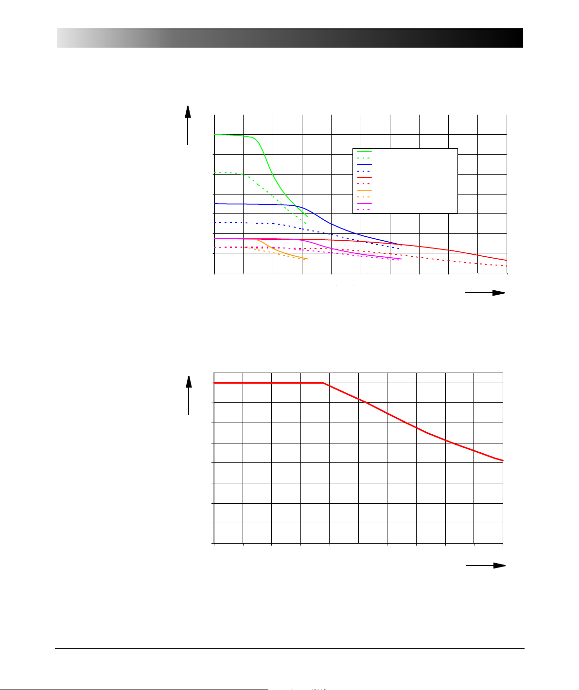
Figure 6-3:
0.0
20.0
40.0
60.0
80.0
100.0
120.0
140.0
160.0
0 102030405060708090100
Output Cu rrent [Arms]
1~ low sensitive 32A (L-L-L-L)
1~ high sensitive 32A (L-L-L-L)
1~ low sensitive 64A (L-L // L-L)
1~ high se nsitive 64A (L-L // L-L)
1~ low sensitive 128A (LL-LN)
1~ high se nsitive 128A (LL-LN // LL-LN)
6~ low sensitive 32A (L-N)
6~ high se nsitive 32A (L-N)
3~ low sensitive 64A (L-N)
3~ high se nsitive 64A (L-N)
Output current in A
rms
Compliance voltage in V
peak
low sensitive 32 A (L-L-L-L)
high sensitive 32 A (L-L-L-L)
low sensitive 64 A (L-L //L-L)
high sensitive 64 A (L-L //L-L)
low sensitive 128 A (LL-LN)
high sensitive 128 A (LL-LN //LL-LN)
low sensitive 32 A (L-N)
high sensitive 32 A (L-N)
low sensitive 64 A (L-N)
high sensitive 64 A (L-N)
0
4
8
12
16
20
24
28
32
0 100 200 300 400 500 600 700 800 900 1000
Frequency [Hz]
Max. Current [A
]
Frequency in Hz
Max. current in A
Typical compliance
voltage (50/60 Hz)
Figure 6-4:
Current derating at high
frequencies for sinusoidal
signals
Technical Data
Compliance Voltage [Vpeak]
The high and low sensitive curves in figure 6-3 correspond to the overload
detection sensitivity settings in the Test Universe software. The low sensitive
curves show the maximum available peak compliance voltage, which is
mainly relevant for testing primary and electromechanical relays.
45
Page 46
CMC 356 Reference Manual
Current in A
Continuous output power in W
Current in A
Continuous output power in W
Figure 6-5:
Typical continuous output
current and output power
at 23 °C;
single-phase mode
Figure 6-6:
Typical continuous output
current and output power
at 23 °C;
three- and six-phase mode
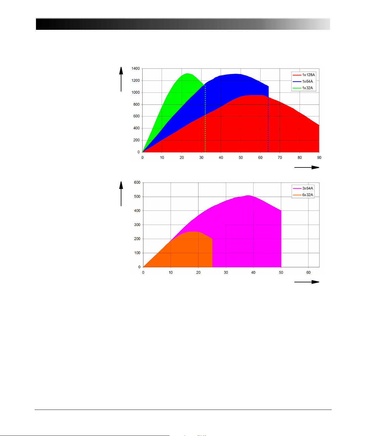
The continuous operating range is given by the area below the curves in the
figure 6-5 and 6-6 above.
If you don’t require more than 64 A, we recommend to use the 1 x 64 A
configuration rather than the 128 A one because the 1 x 64 A configuration
provides more continuous output power.
Due to the large number of operating modes, it is not possible to give
universally applicable curves for the discontinuous mode. However, the
examples given below can be used instead to gain feeling for the possible
output durations (t1 is the possible duration of a cold device).
46
Page 47
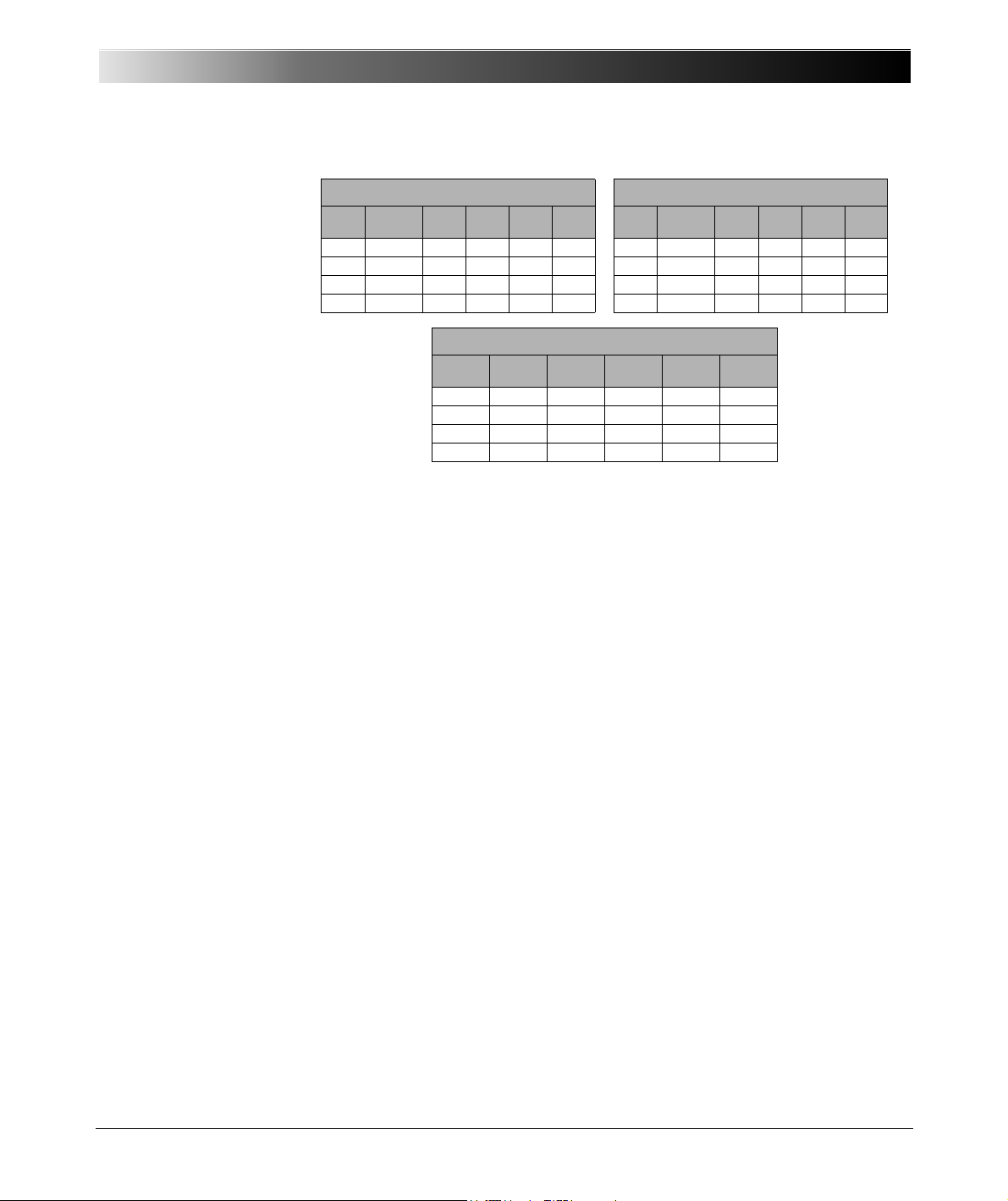
Table 6-6:
Typical duty cycles for
operation at ambient
temperature of 23 °C
Technical Data
6 x 32 A (L-N) 3 x 64 A (L-N)
I
[A]P [W]
0 ... 25 0 ... 1200 100% > 30 > 1800 - 0 ... 50 0 ... 1200 100% > 30 > 1800 -
26 1400 80% 7.5 80 20 52 1400 80% 7.5 80 20
29 1300 75% 6.0 60 20 58 1300 75% 6.0 60 20
32 1200 71% 3.5 50 20 64 1200 71% 3.5 50 20
duty
cycle
t1
[min]
ton
[s]
toff
[s]
I
[A]P [W]
duty
cycle
t1
[min]
ton
[s]
toff
[s]
1 x 128 A (LL-LN)
I
[A]
0 .... 80 0 ... 700 100% > 30.0 > 1800 0
P
duty
[W]
100 450 60% 4.9 30 20
120 300 43% 2.6 15 20
128 200 38% 2.0 12 20
cycle
t1 [min] ton
[s]
toff [s]
47
Page 48
CMC 356 Reference Manual
Footnotes:
1.a) V
L4
(t) automatically
calculated:
V
L4
=(VL1+ VL2+ VL3)*C
C: configurable constant
from –4 to +4.
b) V
L4
can be configured
by software in frequency,
phase, and amplitude.
2. Guaranteed data for
ohmic loads, (PF=1).
Refer to the
accompanying figure of
the output power
curves.
Refer to section 6.3.4,
"Operational Limits in
Conjunction with Mains
Supply" on page 51.
3.Data for three-phase
systems are valid for
symmetric conditions
(0 °, 120 °, 240 °).
4.Data for four-phase
systems are valid for
symmetric conditions
(0 °, 90 °, 180 °, 270 °).
5.rd. = reading;
rg. = range, whereat
n % of rg. means: n % of
upper range value.
6.Valid for sinusoidal
signals at 50/60 Hz.
7. 20 kHz measurement
bandwidth, nominal
value, and nominal load.
8. If you purchased the
option FL-6, the
maximum output
frequency is
constrainedto 599 Hz.
9
Signals above 1 kHz are only supported in selected software modules and are only available
on the voltage outputs and the low level outputs.
Table 6-7: CMC 356 voltage outputs
6.3.3 Voltage Outputs
4 Voltage Outputs
Output voltages
3-phase AC (L-N)
4-phase AC (L-N)
1-phase AC (L-N)
1-phase AC (L-L)
DC (L-N)
Output power
3-phase AC
4-phase AC
1-phase AC (L-N)
1-phase AC (L-L)
DC (L-N)
Accuracy
Harmonic distortion
(THD+N)
Phase error
DC offset voltage < 20 mV < 100 mV
Voltage ranges Range I: 0 ... 150 V
Resolution Range I: 5 mV
Frequency ranges
Short-circuit protect. Unlimited for L - N
Connection 4 mm/0.16 " banana connectors; amplifier
Insulation Reinforced insulation of power supply and all SELV
2
3
4
6, 7
6
8
3 x 0...300V
1
4 x 0...300V
1 x 0...300V
1 x 0...600V
4 x 0 ... ± 300 V
Typical Guaranteed
3 x 100 VA at 100 ... 300 V
4 x 75 VA at 100 ... 300 V
1 x 200 VA at 100 ... 300 V
1 x 275 VA at 200 ... 600 V
1 x 420 W at 300 VDC
Error < 0.03 % of rd.
+ 0.01 % of rg.
3 x 85 VA at 85 ... 300 V
4 x 50 VA at 85 ... 300 V
1x150VA at 75...300V
1 x 250 VA at 200... 600 V
1 x 360 W at 300 VDC
5
Error < 0.08 % of rd.
+ 0.02 % of rg.
0.015 % < 0.05 %
Typical 0.02 ° Guaranteed < 0.1 °
Range II: 0 ... 300 V
Range II: 10 mV
Sinusoidal signals
harmonics/interharm.
transient signals
connection socket V
9
L1-VL3
10 … 1000 Hz
10 … 3000 Hz
DC … 3.1 kHz
interfaces
48
Page 49
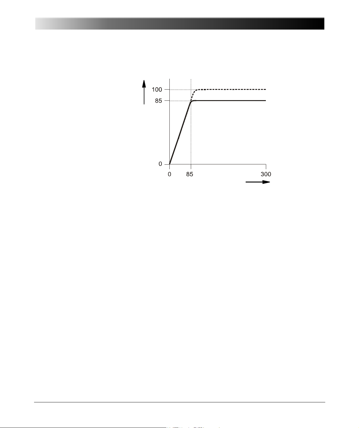
6.3.3.1 Power Diagram for Three-Phase Operation
Output voltage in V
Output power per phase in VA
typical
guaranteed
Figure 6-7:
Power diagram for
three-phase operation
Technical Data
49
Page 50
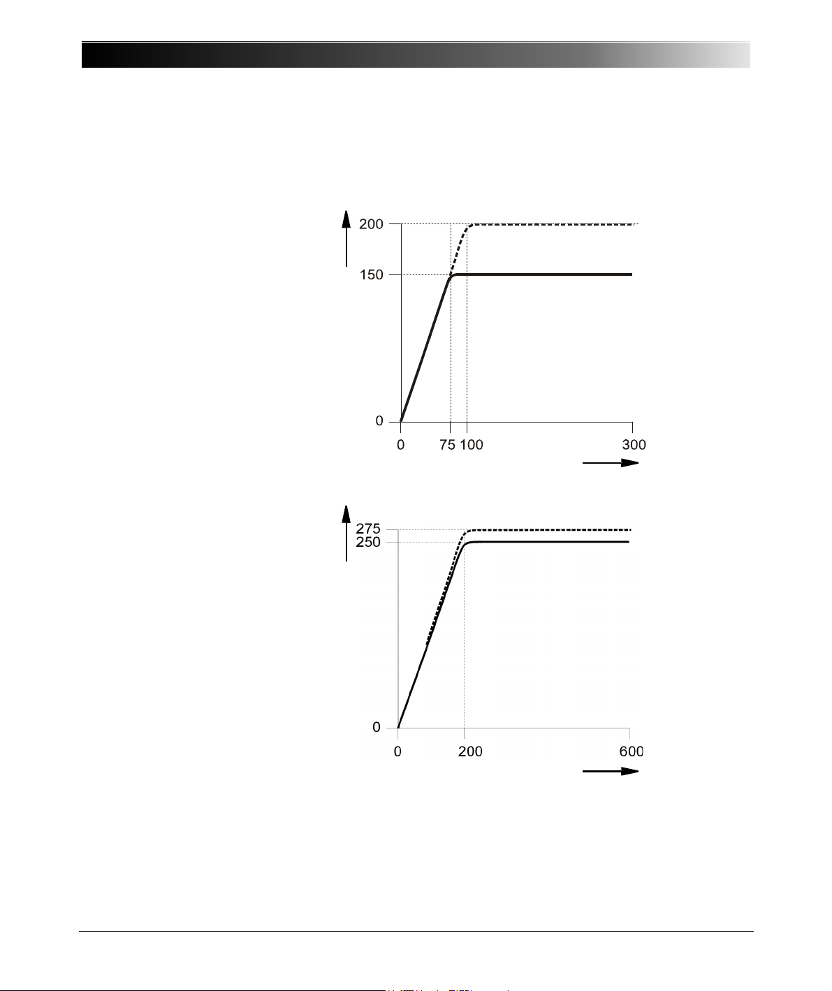
CMC 356 Reference Manual
Output voltage L-N in V
Output power in VA
typical
guaranteed
Output voltage L-L in V
Output power in VA
typical
guaranteed
6.3.3.2 Power Diagram for Single-Phase Operation
Figure 6-8:
Single-phase operation
L-N
Also refer to section 7.2.4, "Single-Phase Voltage" on page 95.
Figure 6-9:
Single-phase operation
L-L
50
Page 51
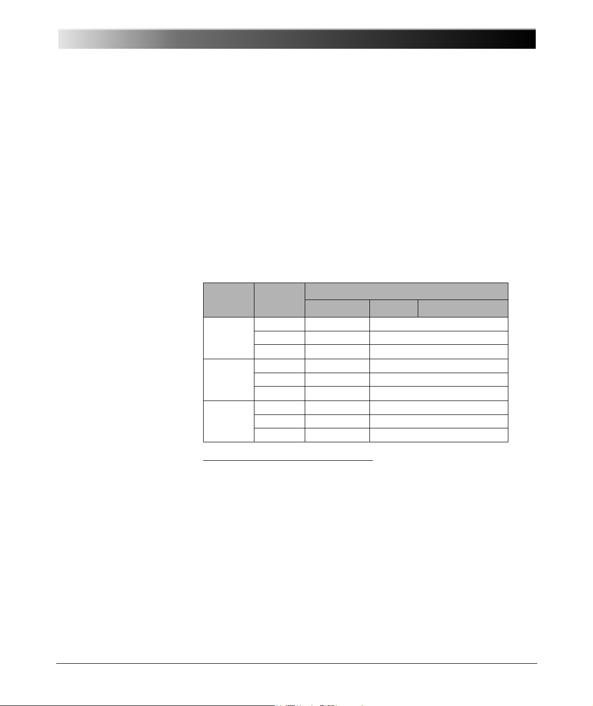
Technical Data
6.3.4 Operational Limits in Conjunction with Mains Supply
Principally, the maximum output power of the CMC 356 is limited by the
mains input supply voltage.
Table 6-8:
Typical total output power
at different mains voltages.
For mains voltages of 115 V
or smaller, it is also possible to supply the
AC
CMC 356 with two phases (L-L) instead of the normal phase-neutral (L-N)
operation in order to increase the supply voltage (115 V * sqrt(3) = 200 V).
In order to limit the internal losses and to maximize the output power of the
voltage amplifier, always set the maximum test object voltage to the
minimum value possible for the test.
Beside the reduction of the available total output power of low line voltages,
no other significant degradations in the technical data of the CMC 356
occur.
Mains
voltage
Current Typical total output power
Currents only Currents AUX DC & voltage
230V 6 x 15 A 1600 W 1190 W + 300 W
6 x 25 A 1470 W 1060 W + 300 W
6x32A 1320W 910W +300W
1
115 V
6x15A 1120W 710W +300W
6 x 25 A 990 W 580 W + 300 W
6 x 32 A 860 W 450 W + 300 W
1
100V
6 x 15 A 910 W 500 W + 300 W
6 x 25 A 790 W 380 W + 300 W
6 x 32 A 670 W 260 W + 300 W
1
After 15 min of continuous operation at full output power a duty cycle of 15 min
on/15 min off is required at an ambient temperature of 25°C. This does not apply to
the 6 x 32 A example because the output duration is limited by the current amplifier
(see Chapter 6.3.2, "Current Outputs" on page 43 for more details).
51
Page 52
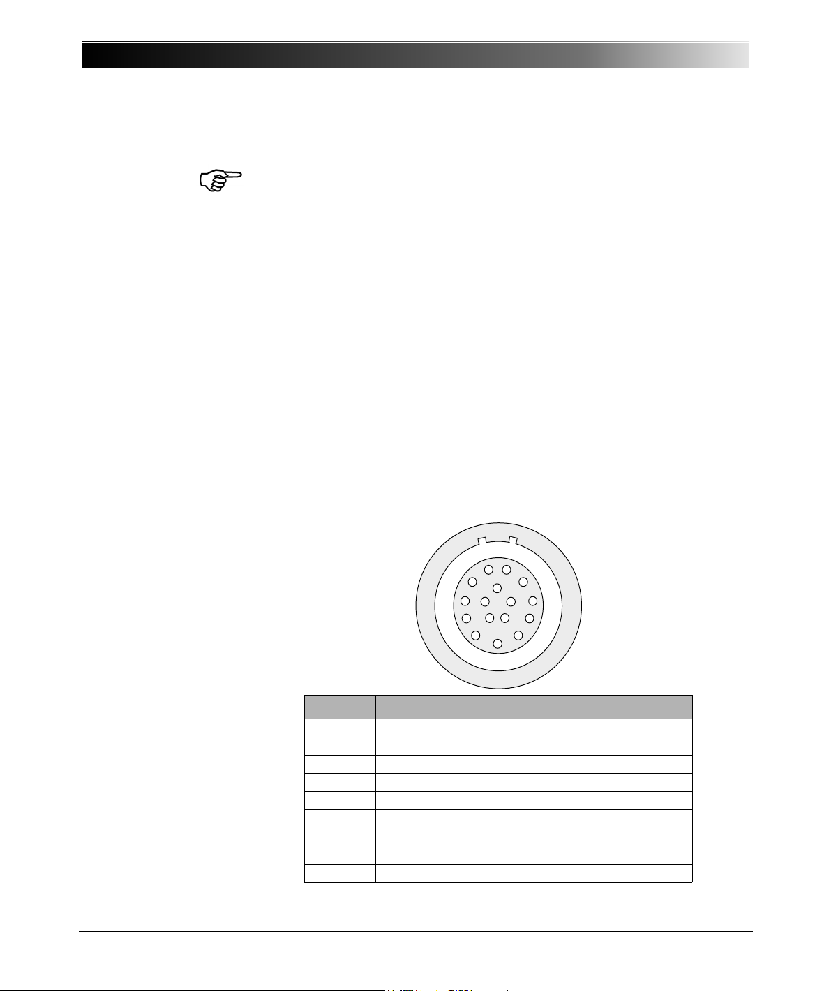
CMC 356 Reference Manual
6.3.5 Low Level Outputs "LL out" for External Amplifiers
Figure 6-10:
Pin assignment of
"LL out 1-6" (lower 16-pole
Lemo socket); view onto
the connector from the
cable wiring side.
Note: The low-level outputs "LL out 7 - 12" are only available, if the option
LLO-2 is installed, refer to section 6.11, "Option LLO-2 (Low Level Outputs)"
on page 90.
Both SELV interface connectors "LL out 1 - 6" as well as the optional
"LL out 7 - 12" (if applicable) hold two independent generator triples each.
These six high accuracy analog signal sources per connector can serve to
either control an external amplifier or to directly provide small signal outputs.
In addition, each SELV interface connector provides a serial digital interface
(pins 8-16; see below) that transmits control and monitor functions between
the CMC 356 and the external amplifiers. Supported devices are the
CMA 156, CMA 56, CMS 156, CMS 251 and CMS 252 (see also 9.6.7,
"CMLIB A" on page 119 and 9.6.9, "Connection Cable for REF 54x Relays
(ABB) with Low Level Signal Inputs" on page 121).
The low level outputs are short-circuit-proof and continually monitored for
overload. They are separated through reinforced insulation from the power
input and from the load outputs (SELV interface). They deliver calibrated
signals in the range from 0 to 7 V
nominal (0 to ± 10 V
eff
peak
).
Both the selection of the particular amplifier as well as the specification of
the range of the amplifier takes place in the Tes t Uni v er se software.
The pin assignment of
"LL out 7-12" socket is
identical.
52
Pin Function LL out 1-6 Function LL out 7-12
Pin 1 LL out 1 LL out 7
Pin 2 LL out 2 LL out 8
Pin 3 LL out 3 LL out 9
Pin 4 Neutral (N) connected to GND
Pin 5 LL out 4 LL out 10
Pin 6 LL out 5 LL out 11
Pin 7 LL out 6 LL out 12
Pin 8-16 For internal purposes
Housing Screen connection
Page 53
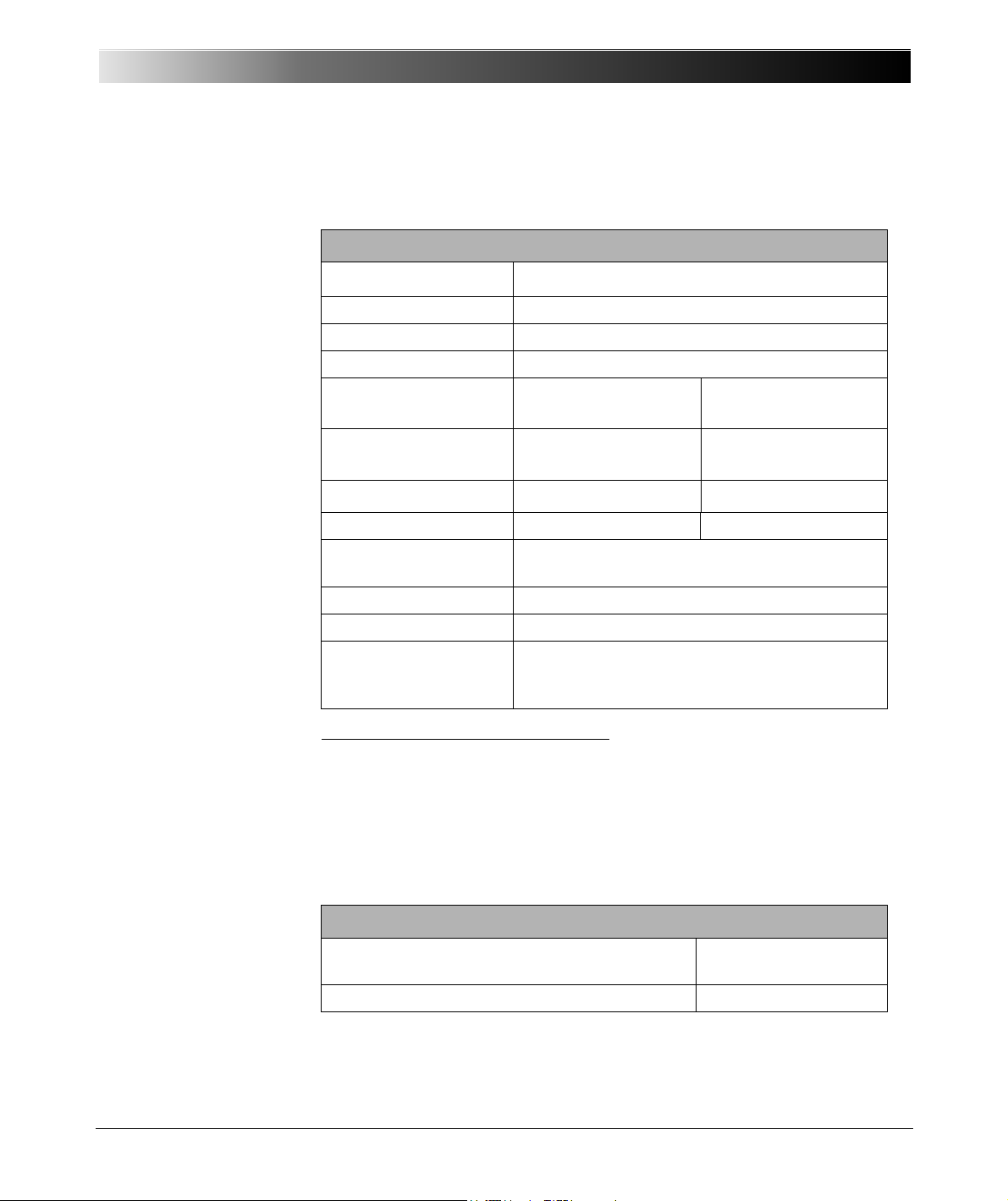
Table 6-9:
Data for SELV outputs
"LL out"
Technical Data
"LL out 1-3" and "LL out 4-6" (and optionally "LL out 7-9" and "LL out 10-12")
each make up a selectable voltage or current triple.
6 Outputs "LL out 1 - 6" and 6 (optional) outputs "LL out 7 - 12"
Output voltage range
Frequency range
2
0…±10 V
0 … 3000 Hz
peak
1
Output current Max. 1 mA
Resolution < 250
µ
V
Accuracy Typical < 0.025 % Guaranteed < 0.07 %
Harmonic distortion
(THD+N)
Phase error
3
4
Typical < 0.015 % Guaranteed < 0.05 %
Typical 0.02 ° Guaranteed < 0.1 °
DC offset voltage Typical < 150
Unconventional CT/VT
Linear or Rogowski
for 1…10 V
µ
V Guaranteed < 1.5 mV
5
mode
peak
simulation
Overload indication Yes
Short-circuit protection Unlimited to GND
Insulation Reinforced insulation to all other potential groups
of the test equipment. GND is connected to
protective earth (PE).
Table 6-10:
Ordering Information
1
Input OMICRON amplifier nominal: 0 ... 5 V
2
If you purchased the option FL-6, the maximum output frequency is constrained to 599 Hz.
3
Values at nominal voltage (10 V
4
Valid for sinusoidal signals at 50/60 Hz.
5
When simulating Rogowski sensors, the output voltage is proportional to the derivative of the
current with respect to time (di(t)/dt).
peak
rms
), 50/60 Hz, and 20 kHz measurement bandwidth.
Ordering Information
Connector for two guide notches and pull relief
FGB.2B.316.CLAD 72Z
(for "LL out")
Black anti-bend cable cover GMA.2B.070 DN
For a manufacturer description about the connection sockets "LL out" and
"ext. Interf.", visit the Web site www.lemo.com.
53
Page 54

CMC 356 Reference Manual
Pin Function
Pin 1 Counter input 1
Pin 2 Counter input 2
Pin 3 Reserved
Pin 4 Neutral (N) connected to GND
Pin 5 Binary output 11
Pin 6 Binary output 12
Pin 7 Binary output 13
Pin 8 Binary output 14
Pin 9 Reserved
Housing Screen connection
6.3.6 Low-Level Binary Outputs ("ext. Interf.")
Figure 6-11:
Pin assignment of "ext.
Interf." (upper 16-pole
Lemo socket); view onto
the connector from the
cable wiring side
The SELV interface connector "ext. Interf." holds four additional transistor
binary outputs (Bin. out 11 - 14). Unlike regular relay outputs,
Bin. out 11 - 14 are bounce-free binary outputs (small signals) and have a
minimal reaction time.
In addition, two high frequency counter inputs for up to 100 kHz are
available for the testing of energy meters. They are described in section
6.4.2, "Counter Inputs 100 kHz (Low Level)" on page 61.
Table 6-11:
Data of the low-level
binary outputs 11 - 14
54
4 Low-Level Transistor Binary Outputs (Bin. out 11 - 14)
Type Open-collector transistor outputs;
Switching voltage Max. 15 V
Max. input voltage ±16 V
Switch current Max. 5 mA (current limited); min. 100
Actualization time 100
Rise time
Connection Connector "ext. Interf." (CMC 356 rear side)
Insulation Reinforced insulation to all other potential
external pull-up resistor
µ
s
µ
<3
s (V
extern
=5V, R
pullup
=4.7kΩ)
groups of the test equipment. GND is
connected to protective earth (PE).
µ
A
Page 55
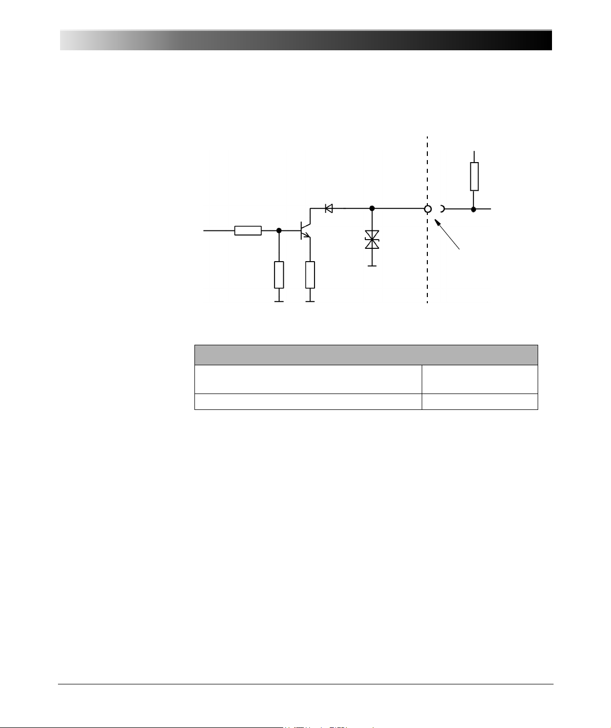
Figure 6-12:
Rear side
of CMC 356
R
pullup
Inside of CMC 356
16 V
47
Ω6.8 kΩ
22 kΩ
V
extern
= 5 ... 15 V
Binary outputs 11 ... 14
"ext. Interf."
Circuit diagram of
"ext. Interf." binary
transistor outputs 11
Table 6-12:
Ordering Information
Technical Data
- 14
Ordering Information
Connector for one guide notch and pull relief
FGG.2B.316.CLAD 72Z
(for "ext. Interf")
Black anti-bend cable cover GMA.2B.070 DN
For a manufacturer description about the connection sockets "LL out" and
"ext. Interf.", visit the Web site www.lemo.com.
55
Page 56
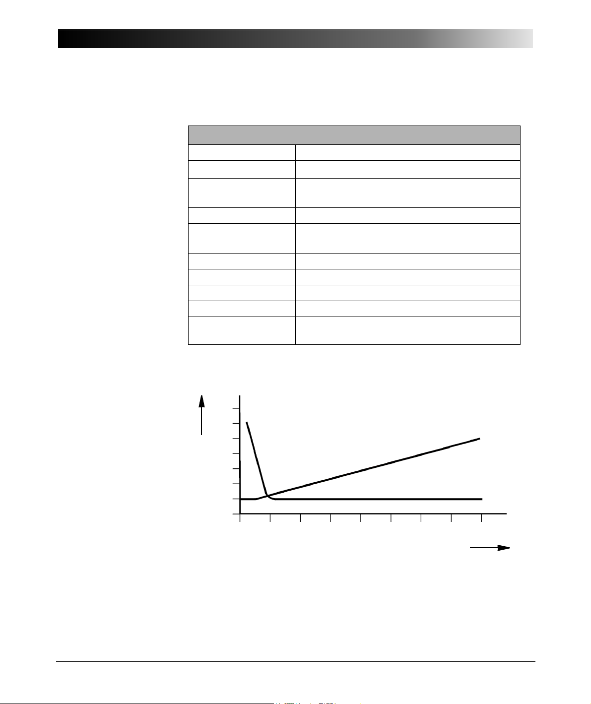
CMC 356 Reference Manual
350
300
250
200
150
100
50
0
UinV / PinW
Current in A
012 345678
P
U
6.3.7 Binary Output Relays
Table 6-13:
Data of binary output
relays
4 Binary Output Relays (Binary Outputs 1-4)
Type Potential-free contacts; software-controlled
AC loading V
DC loading V
300 VAC; I
max
300 VDC; I
max
max
max
8 A; P
8A; P
2000 VA
max
max
50 W
(refer to load limit curve)
Switch-on current 15 A (max. 4 s at 10 % duty-cycle)
Electrical lifetime 100 000 switching cycles at 230 V
/ 8 A and
AC
ohmic load
Pickup time Approx. 6 ms
Fall back time Approx. 3 ms
Bounce time Approx. 0.5 ms
Connection 4 mm/0.16 " banana sockets
Insulation Reinforced insulation from all SELV interfaces and
from power supply.
The accompanying diagram shows the load limit curve for DC voltages. For
AC voltages, a maximum power of 2000 VA is achieved.
Figure 6-13:
Load limit curve for relays
on the binary outputs with
DC voltages
56
Page 57
Table 6-14:
DC Voltage supply
AUX DC
6.3.8 DC Supply (AUX DC)
DC Supply (AUX DC)
Voltage ranges 0 ... 66 V
Power Max. 50 W
Accuracy
Resolution < 70 mV
Connection 4 mm/0.16 " banana sockets on front panel
Short-circuit protection Yes
Overload indication Yes
Insulation Reinforced insulation from power supply and
1
Technical Data
(max. 0.8 A)
DC
0 ... 132 V
0 ... 264 V
(max 0.4 A)
DC
(max. 0.2 A)
DC
Error: typical < 2 %, guaranteed < 5 %
all SELV interfaces
1
Percentage is with respect to each range's full-scale.
57
Page 58
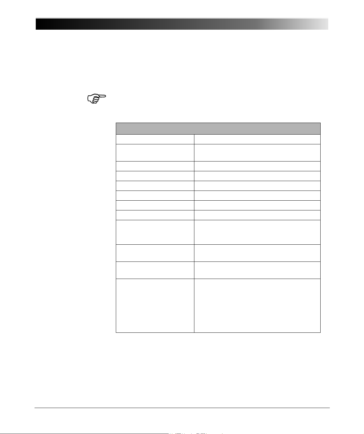
CMC 356 Reference Manual
6.4 Inputs
6.4.1 Binary Inputs
Table 6-15:
General data of
binary inputs
Note: If option ELT-1 is installed, only the general binary input data given in
the following Table 6-15 are valid. For detailed information about the option
ELT-1, please refer to section 6.10, "Option ELT-1" on page 67.
General Data of Binary Inputs 1…10
Number of binary inputs 10
Trigger criteria Potential-free or DC-voltage compared to
threshold voltage
Reaction time Max. 220
µ
s
Sampling frequency 10 kHz
Time resolution 100
µ
s
Max. measuring time Unlimited
Debounce time 0…25 ms (refer to page 60)
Deglitch time 0…25 ms (refer to page 60)
Counting function
counter frequency
pulse width
3 kHz (per input)
>150
µ
s (for high and low signals)
Configuration Binary inputs can be configured. Refer to the
OMICRON Test Universe Help.
Connection 4 mm/0.16 " banana sockets on the front
panel
Insulation 5 galvanic insulated binary groups with each
2 inputs having its own GND.
Operation insulation to the power outputs, DC
inputs and between galvanically separated
groups.
Reinforced insulation from all SELV
interfaces and from power supply.
58
Page 59
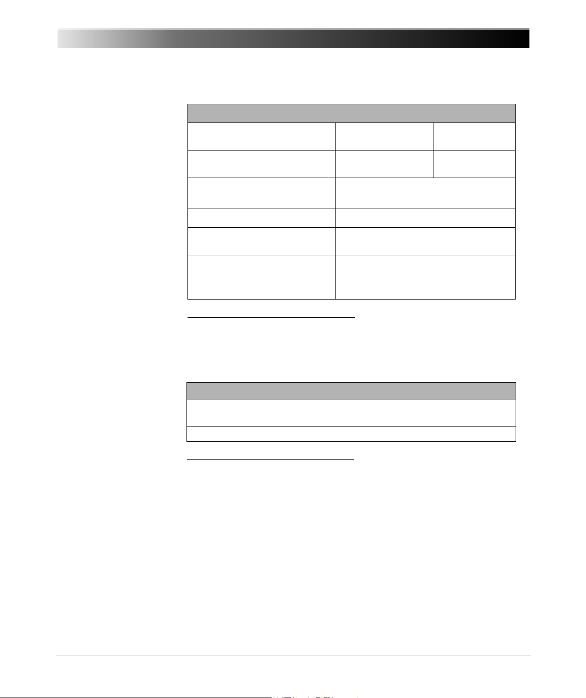
Table 6-16:
Data for potential-sensing
operation
Data for Potential-Sensing Operation
Threshold voltage data per input
Setting range Resolution
range
Range I
Range II
0...20V
>20...300V
Max. input voltage CAT III/ / 300 V
CAT IV / 150 V
Technical Data
50mV
500mV
rms
rms
Table 6-17:
Data for potential-free
operation
Threshold voltage accuracy1
5% of rd. + 0.5% of rg.
Threshold voltage hysteresis Range I: typ. 60 mV
Range II: typ. 900 mV
Input impedance
Threshold 0...20V
Threshold 20...300V
1
Applies to positive voltage signal edge; value shown in % of reading (rd.) + % of upper range
value (rg.)
2
Refer to figure 5-2, "Simplified circuit diagrams of binary inputs and outputs (CMC 356
standard, without option ELT-1 installed)" on page 28.
Data for Potential-Free Operation
Trigger criteria
2
210 kΩ
135 kΩ
1
Logical 0: R > 100 k
Ω
Logical 1: R < 10 kΩ
Input impedance
1
Refer to figure 5-2, "Simplified circuit diagrams of binary inputs and outputs (CMC 356
standard, without option ELT-1 installed)" on page 28.
216 k
Ω
59
Page 60
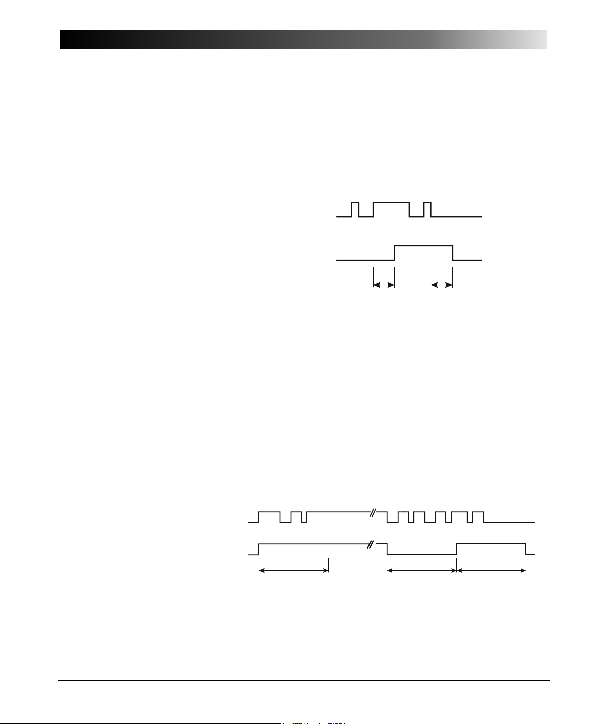
CMC 356 Reference Manual
Input signal
Input signal deglitched
T
deglitch
T
deglitch
Input signal
Input signal
debounced
T
debounce
T
debounce
T
debounce
Figure 6-14:
Signal curve, deglitching
input signals
Deglitching input signals
In order to suppress short spurious pulses a deglitching algorithm could be
configured. The deglitch process results in an additional dead time and
introduces a signal delay. In order to be detected as a valid signal level, the
level of an input signal must have a constant value at least during the
deglitch time. The figure below illustrates the deglitch function.
Debouncing input signals
Figure 6-15:
Signal curve, debounce
input signals
For input signals with a bouncing characteristic, a debounce function can be
configured. This means that the first change of the input signal causes the
debounced input signal to be changed and then be kept on this signal value
for the duration of the debounce time.
The debounce function is placed after the deglitch function described above
and both are realized by the firmware of the CMC 356 and are calculated in
real time.
The figure below illustrates the deglitch function. On the right-hand side of
the figure, the debounce time is too short. As a result, the debounced signal
rises to “high” once again, even while the input signal is still bouncing and
does not drop to low level until the expiry of another period T
debounce
.
60
Page 61
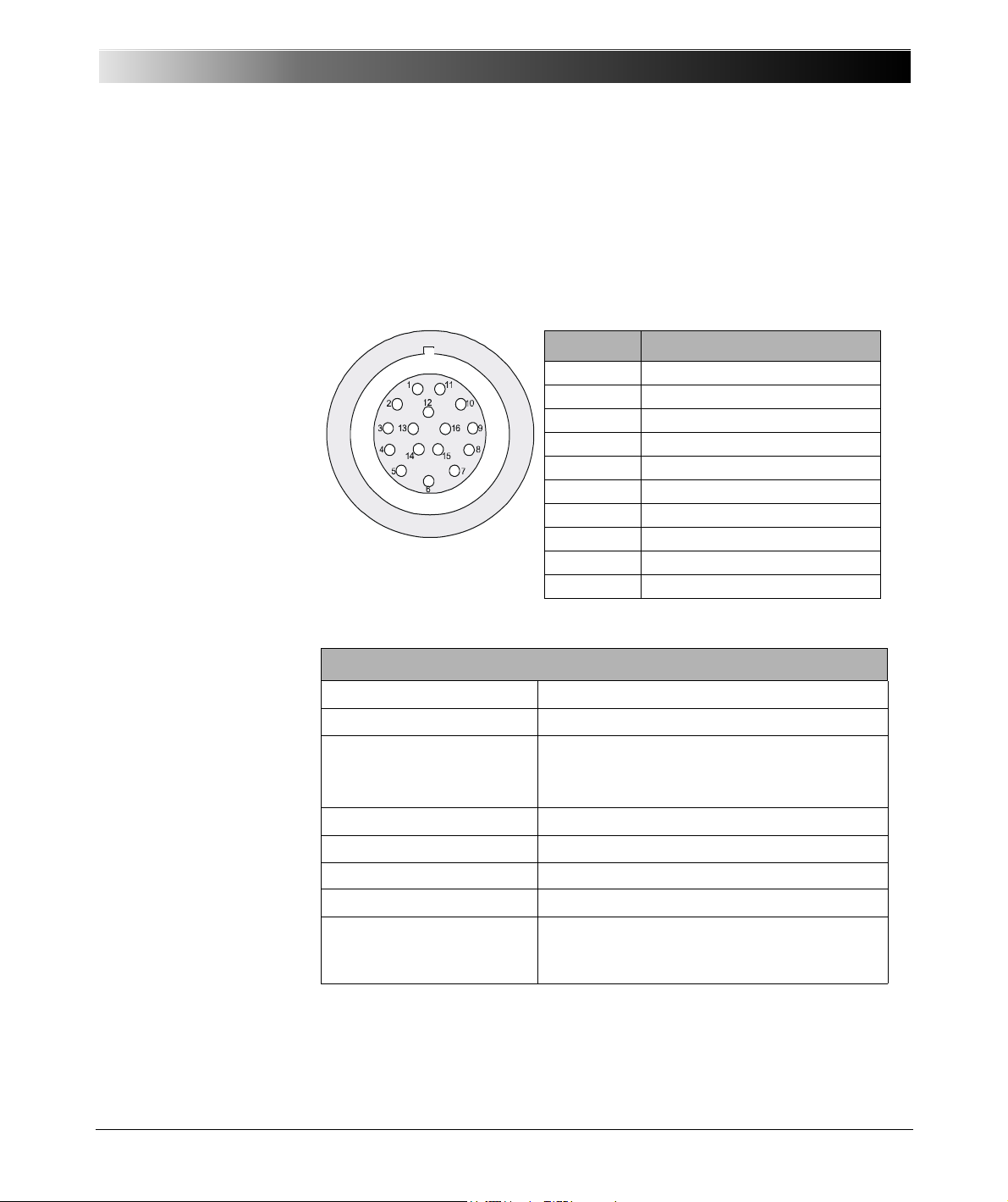
6.4.2 Counter Inputs 100 kHz (Low Level)
Pin Function
Pin 1 Counter input 1
Pin 2 Counter input 2
Pin 3 Reserved
Pin 4 Neutral (N) connected to GND
Pin 5 Binary output 11
Pin 6 Binary output 12
Pin 7 Binary output 13
Pin 8 Binary output 14
Pin 9 Reserved
Housing Screen connection
Figure 6-16:
Pin assignment of "ext.
Interf." (upper 16-pole
Lemo socket); view onto
the connector from the
cable wiring side
Technical Data
The SELV interface connector "ext. Interf." holds two high frequency counter
inputs for up to 100 kHz are available for the testing of energy meters.
In addition, four transistor binary outputs (Bin. out 11 - 14) are available.
They are described in section 6.3.6, "Low-Level Binary Outputs ("ext.
Interf.")" on page 54.
Table 6-18:
Counter inputs 100 kHz
2 Counter Inputs
Max. counter frequency 100 kHz
Pulse width > 3 µs (high and low signal)
Switch threshold
pos. edge
neg. edge
max. 8 V
min. 4 V
Hysteresis typ. 2 V
Rise & fall times < 1 ms
Max. input voltage ± 30 V
Connection Socket "ext. Interf." (rear CMC 356)
Insulation Reinforced insulation to all other potential
groups of the test equipment. GND is
connected to protective earth (PE).
61
Page 62
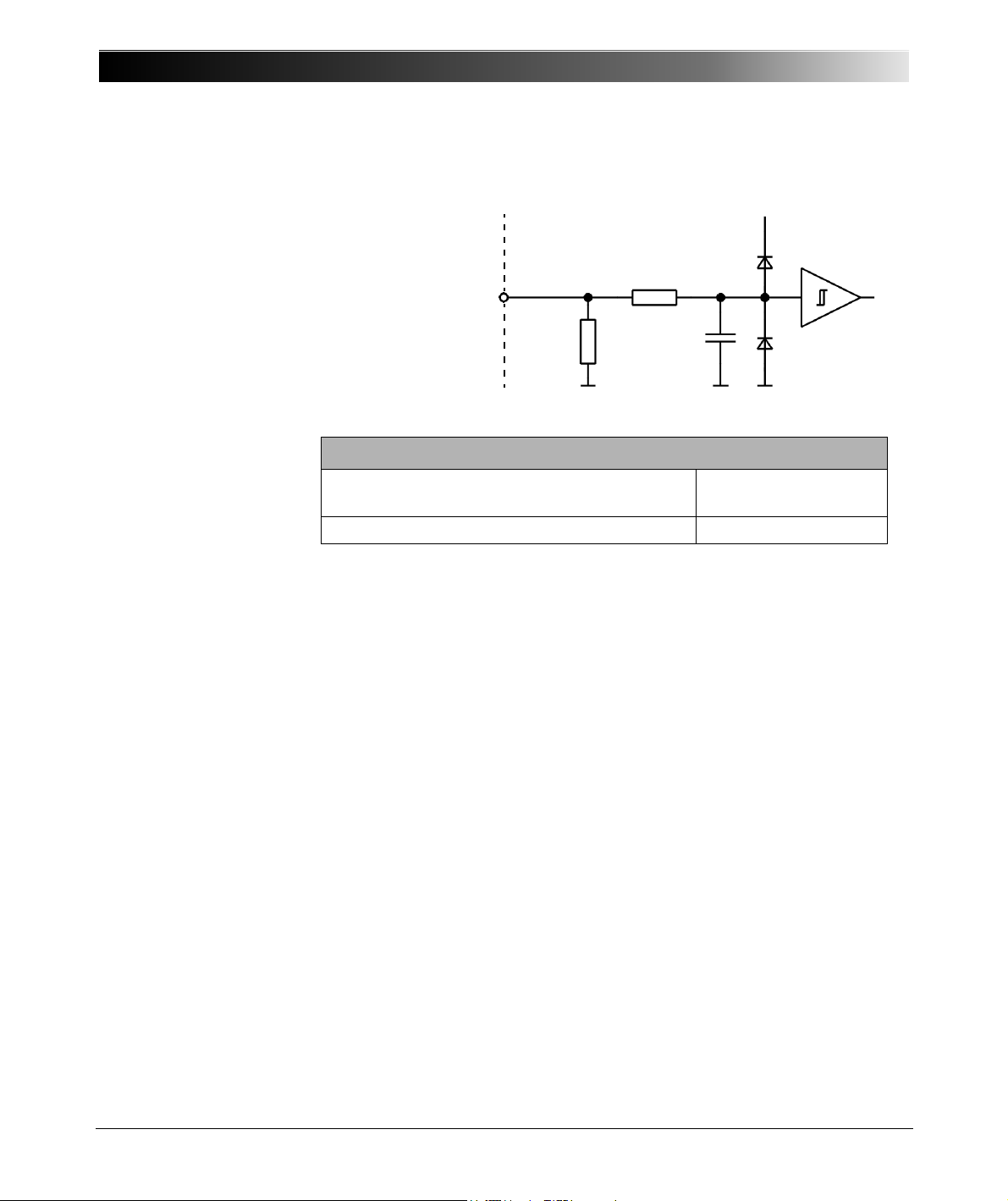
CMC 356 Reference Manual
Rear side
of CMC 356
+15 V
100 k
Ω
22 kΩ
47 pF
Inside of
CMC 356
Counter inputs 1 & 2
"ext. Interf."
Figure 6-17:
Circuit diagram of
"ext. Interf." counter inputs
1 and 2
Table 6-19:
Ordering Information
Ordering Information
Connector for one guide notch and pull relief
FGG.2B.316.CLAD 72Z
(for "ext. Interf")
Black anti-bend cable cover GMA.2B.070 DN
For a manufacturer description about the connection sockets "LL out 1-6"
and "ext. Interf.", visit the Web site www.lemo.com.
62
Page 63

6.5 Technical Data of the Ethernet Ports
Originally, CMC 356 test sets were delivered with a so-called NET-1 board
that holds two different Ethernet ports:
ETH1: a 10/100Base-TX Ethernet port
ETH2: a 100Base-FX (optical fiber) Ethernet port.
With the introduction of the front panel control device CMControl, the
CMC 356 test sets are now equipped with a NET-1B board that holds two
identical PoE (Power over Ethernet) ports ETH1 and ETH2.
CMC 356 test sets with NET-1 board can be upgraded with the new NET-1B
board to be able to communicate with the new CMControl and have
Ethernet access at the same time.
6.5.1 The NET-1B Board
Ethernet ports ETH1 and ETH2
Technical Data
Type 10/100Base-TX (10/100Mbit,
twisted pair, auto-MDI/MDIX or
auto-crossover)
Connector RJ45
Cable type LAN cable of category 5 (CAT5)
or better
Status indication Green LED: physical link present
Yellow LED: traffic on interface
Power over
Ethernet (PoE)
IEEE 802.3af compliant.
Port capability limited to one Class 1
(3.84 W) and one Class 2 (6.49 W)
power device.
63
Page 64
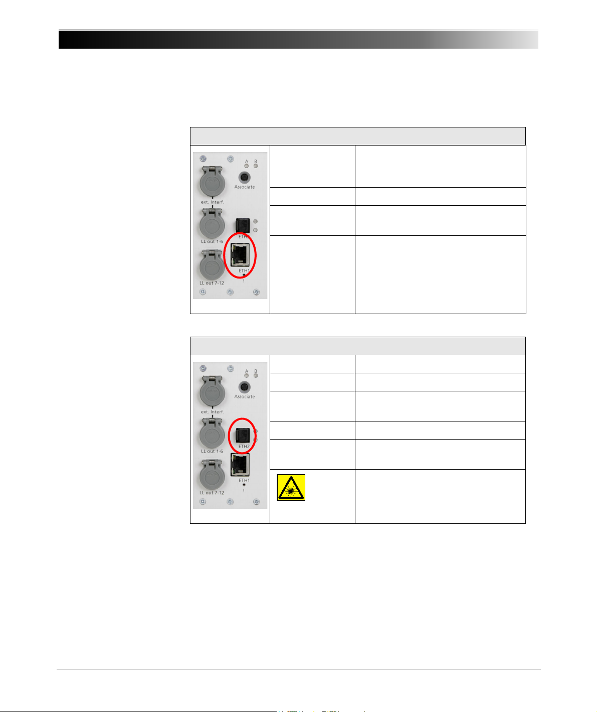
CMC 356 Reference Manual
6.5.2 The NET-1 Board
Table 6-20:
Technical data of the
NET-1 Ethernet port ETH1
Ethernet port ETH1
Type 10/100Base-TX (10/100Mbit,
twisted pair, auto-MDI/MDIX or
auto-crossover)
Connector RJ45
Cable type LAN cable of category 5 (CAT5)
or better
Status indication Green LED: physical link present
Yellow LED: traffic on interface
Table 6-21:
Technical data of the
NET-1 Ethernet port ETH2
Ethernet port ETH2
Type 100Base-FX (100Mbit, fiber, duplex)
Connector MT-RJ
Cable type 50/125 µm or 62.5/125 µm (duplex
patch cable)
Cable length > 1 km (0.62 miles) possible
Status idication Green LED: physical link present
Yellow LED: traffic on interface
This is a product of Laser Class 1
(IEC 60825)
64
Page 65
Table 6-22:
Climate
Table 6-23:
Shock and vibration
Technical Data
6.6 Environmental Conditions
6.6.1 Climate
Climate
Operating temperature 0 ... +50 °C;
above +30 °C a 50 % duty cycle may apply.
Storage and transportation -25 … +70 °C
Max. altitude 2000 m
Humidity 5 … 95% relative humidity; no condensation
Climate Tested according to IEC 68-2-78
6.6.2 Shock and Vibration
Dynamics
Vibration Tested according to IEC 60068-2-6
(operating mode); frequency range
10 ... 150 Hz; acceleration 2 g continuous
(20 m/s²); 10 cycles per axis
Shock Tested according to IEC 60068-2-27
(operating mode); 15 g / 11 ms, half-sinusoid,
each axis
6.7 Mechanical Data
Table 6-24:
Data regarding size and
weight
6.8 Cleaning
Size, Weight and Protection
Weight 16.8 kg (37 lbs)
Dimensions W x H x D (without handle) 450 x 145 x 390 mm
(17.7x5.7x15.4")
Housing IP20 according to EN 60529
To clean the CMC 356, use a cloth dampened with isopropanol alcohol or
water. Prior to cleaning, always switch off the power switch and unplug the
power cord from the mains.
65
Page 66

CMC 356 Reference Manual
6.9 Safety Standards, Electromagnetic Compatibility
Table 6-25:
CE conformity, certified
Safety Standards and
EMC-compatibility
(EMC) and Certificates
CE Conformity, Requirements
The product adheres to the specifications of the guidelines of the council of
the European Community for meeting the requirements of the member
states regarding the electromagnetic compatibility (EMC) Directive
89/336/EEC and the low voltage Directive 73/23/EEC.
EMC
Emission
Europe
International
USA
Immunity
Europe
International
EN 61326; EN 61000-6-4; EN 61000-3-2/3
IEC 61326; IEC 61000-6-4; IEC 61000-3-2/3
FCC Subpart B of Part 15 Class A
EN 61326; EN 61000-6-2; EN 61000-4-2/3/4/5/6/11
IEC 61326; IEC 61000-6-2; IEC 61000-4-2/3/4/5/6/11
Certified Safety Standards
Europe EN 61010-1
Insulation of PC and SELV interfaces complies with
EN 60950-1
International
USA
Canada
IEC 61010-1
UL 61010-1
CAN/CSA-C22.2 No 61010-1-04
Certificate
Manufactured under an ISO9001 registered system
66
Page 67
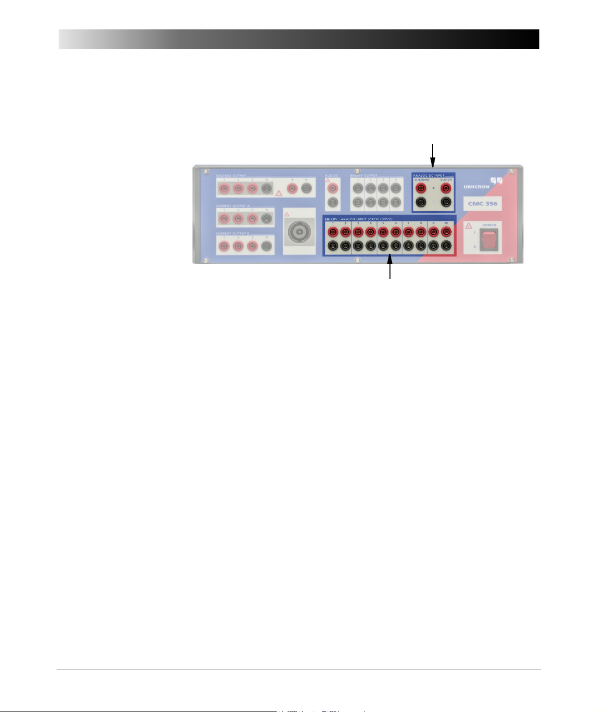
6.10 Option ELT-1
Binary/analog inputs
Analog DC Inputs
Figure 6-18:
Binary/analog inputs and
inputs for analog DC
measurement
Technical Data
The ELT-1 option enables the CMC 356 to measure analog signals:
• Analog DC inputs (+/-10V and either +/-1mA or +/-20mA) for basic
transducer testing with the test module QuickCMC.
• Basic voltage and current measurements with up to three of the 10
analog measurement inputs (restricted EnerLyzer mode).
In addition, the Test U ni ve rse module EnerLyzer provides the following
functionality:
• Simultaneous measurement of up to 10 voltages and/or currents.
• Evaluation of DC components (DC voltages or DC currents).
• Real-time indication of effective values (true RMS) for all measurement
signals.
• Peak values indication (U
peak
, I
peak
,...).
• Phase angles with reference to a given input signal.
• Real-time calculation of apparent, reactive, and active power (in any
configuration).
• Frequency and spectrum indication (harmonic diagrams) of periodic
signals.
• Capturing of transient input signals with different sampling rates.
• Different triggering options for transient signal capturing (basic triggers
and power quality triggers).
• Trend Recording: Measurement of RMS current, RMS voltage,
frequency, phase, active, apparent and reactive power and power factor
over long periods of time (up to 4 million samples possible).
67
Page 68

CMC 356 Reference Manual
6.10.1 General Data
Using the CMC 356 test set in combination with the Test Universe module
Transducer enables advanced testing of multifunctional single-phase and
three-phase electrical transducers with symmetrical or non-symmetrical
operating characteristics.
The hardware option ELT-1 can either be ordered with the new test set or
later as a factory upgrade (the CMC 356 needs to be returned to
OMICRON).
The actual capturing of the measurement values and the range switching for
the channels takes place in the analog input stages AFE (A
E
nd). Each AFE is used by two input channels and galvanically separated
nalog Front
from the other input stages.
The measured values are passed through an isolation amplifier to the
"Measurement Unit" and digitized by an A/D converter. The further
processing is done by a high-performance floating point digital signal
processor (DSP).
As such, apparent power, reactive power, active power, etc., can be
provided in real-time and transmitted to the PC.
The analog measurement inputs have five measurement ranges that can be
configured individually in the test module EnerLyzer.
• 100 mV
•1V
•10V
• 100 V
• 600 V
These range limits refer to the respective rms values of sinusoidal input
signals. The ranges 100 mV, 1 V, 10 V and 100 V can be overloaded
approximately with 10 %.
Input impedance: 500 kOhm || 50 pF for all measurement ranges.
Overload protection: 600 Vrms (± 850 Vpeak) from reference potential N,
from another input, or protective earth (GND).
The sampling rate can be configured by software:
• 28.44 kHz
•9.48kHz
68
•3.16kHz
Page 69
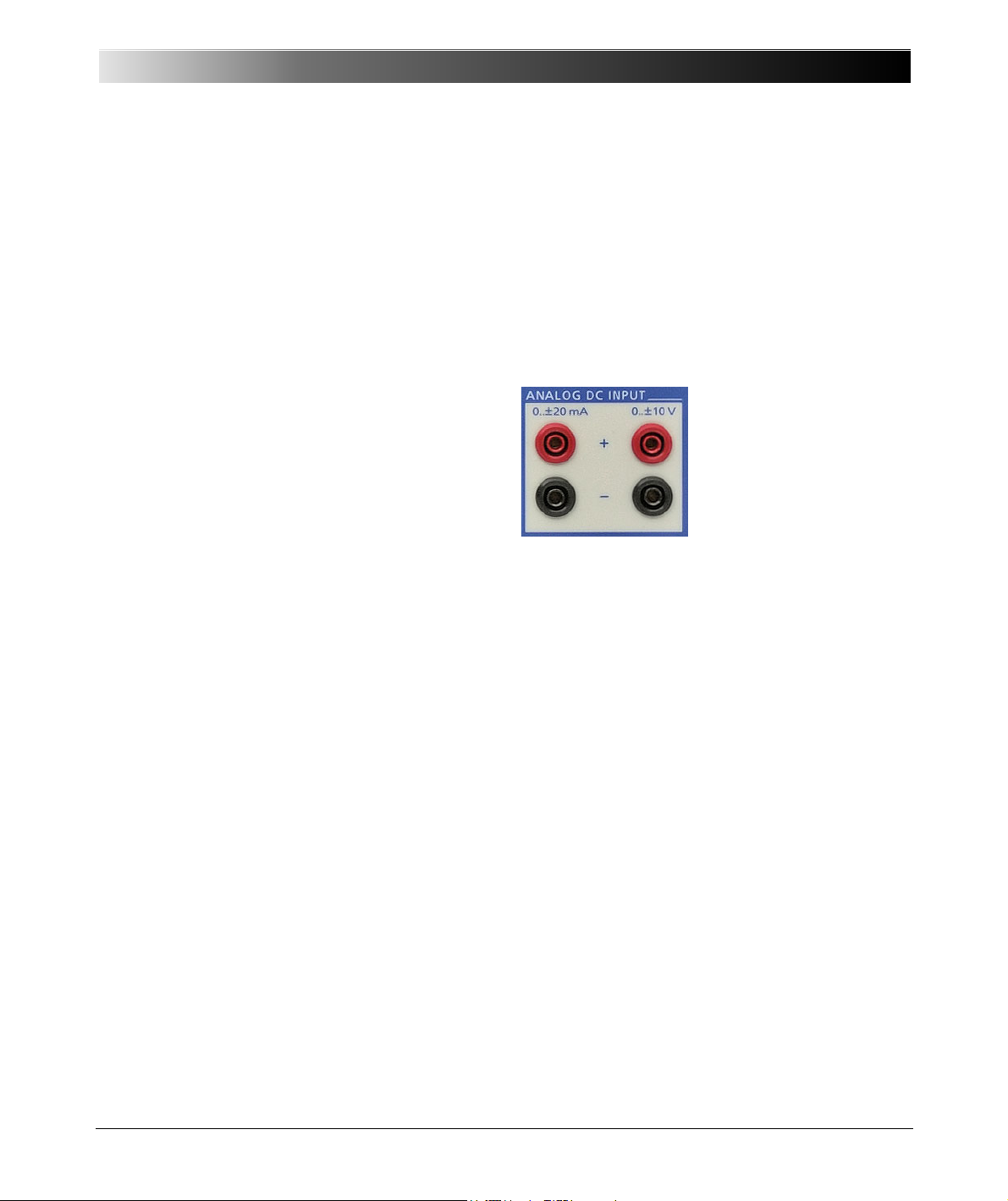
Four different operating modes are possible:
• Multimeter Mode (section 6.10.6)
• Harmonic Analysis (section 6.10.7)
• Transient Recording (section 6.10.8)
• Trend Recording (section 6.10.9)
Technical Data
6.10.2 Analog DC Input (V
Figure 6-19:
DC measurement unit
(analog inputs V
DC
, IDC)
DC, IDC
)
The measurement of analog DC signals has been implemented to enable
the testing of transducers. The measurement unit consists of
• a highly accurate voltage reference,
• one ADC (Analog Digital Converter) for each input, and
• the respective input circuits (i.e., accurate voltage divider, shunt, filter).
The DC measurement unit measures the input signals V
and IDC and
DC
performs the evaluation and forwarding of the measurement values.
Input I
input is protected by a reversible input fuse. The inputs V
has two measurement ranges: 0 … ± 20 mA and 0 … ± 1mA. The
DC
and IDC
DC
reference a common neutral N. The DC measurement unit is galvanically
isolated from all other connections on the front panel.
69
Page 70
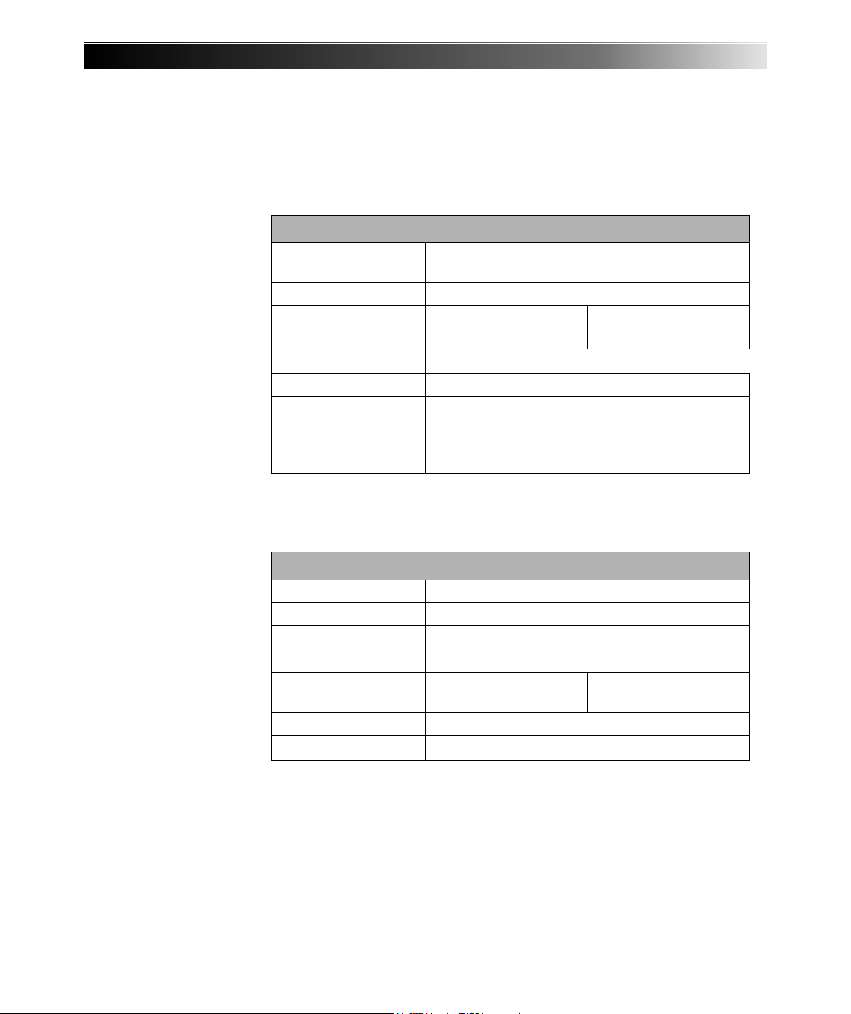
CMC 356 Reference Manual
6.10.3 Accuracy of the Analog DC Input
Table 6-26:
DC measurement input
Note: Exceeding the specified input values can damage the measurement
inputs!
DC Measurement Input IDC
Measurement ranges 0 ... ±1 mA
0 ... ±20 mA
Max. input current 600 mA
Accuracy Typical error
<0.003%ofrg.
Input impedance
Approx. 15
1
Ω
Guaranteed error
<0.02%ofrg.
Connection 4 mm/0.16 " banana connectors
Insulation Insulation to all other front panel connections.
Reinforced insulation from all SELV interfaces and
from power supply.
Not galvanically isolated from V
DC
.
Table 6-27:
DC voltage measurement
input
1
rg. = range, whereat n % of rg. means: n % of upper range value.
DC Voltage Measurement Input VDC
Measurement range 0…± 10 V
Max. input voltage ± 11 V
Input impedance
1M
Ω
Max. input current ± 90 mA
Accuracy Typical error
<0.003%ofrg.
Guaranteed error
<0.02%ofrg.
Connection 4 mm/0.16 " banana connectors
Insulation Not galvanically isolated from I
DC
70
Page 71

6.10.4 Measuring Currents
Since the analog inputs of the CMC 356 are voltage inputs, current
measurement has to be performed using suitable active current clamps with
voltage outputs or shunt resistors.
OMICRON offers the C-PROBE1 as a suitable current clamp (refer to
section 9.5, "Current Clamp C-PROBE1" on page 112). The C-PROBE1 is
not included in the scope of delivery of option ELT-1 and thus has to be
ordered separately.
For further information, please contact OMICRON electronics (refer to
section "Contact Information / Technical Support" on page 137).
Technical Data
71
Page 72
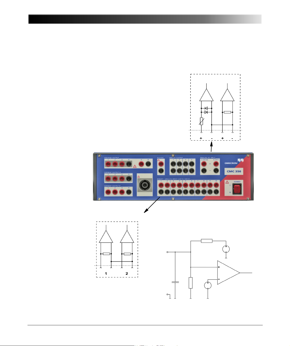
CMC 356 Reference Manual
ANALOG DC INPUT
Only available with option ELT-1.
PTC
0-±20mA 0-±10V
BINARY/ANALOG INPUT
500kΩ 500kΩ
3 - 10 identical
Circuit diagram of a binary input
for potential-free operation
240 kΩ
500kΩ
25 pF
Vin +
Vin -
2.5V
12V
Vcomp
1MΩ
6.10.5 Accuracy of Binary/Analog Inputs with Option ELT-1
Figure 6-20:
Simplified diagrams of
analog and binary inputs
with option ELT-1 installed
The technical data for the binary inputs change with the installation of option
ELT-1.
72
Page 73
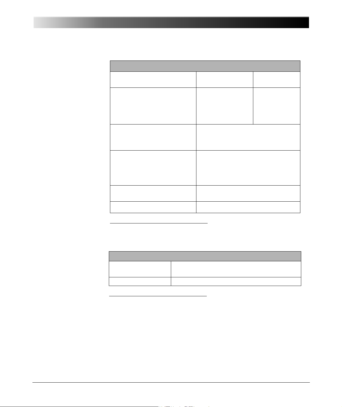
Table 6-28:
Data for potential-sensing
operation
Data for Potential-Sensing Operation
Threshold voltage data per input
Setting range Resolution
range
100 mV
1V
10 V
100 V
600 V
±140mV
±1.4V
±14V
±140V
±600V
Max. input voltage CAT II / 600 V
CAT III/ / 300 V
CAT IV / 150 V
Threshold voltage accuracy1
per range:
Error:
(850 Vpk)
rms
rms
rms
Technical Data
2mV
20 mV
200 mV
2V
20 V
Table 6-29:
Data for potential-free
operation
6.10.6 Multimeter Mode
100mV, 1V, 10V, 100V,
600 V
typical < 2 %, guaranteed < 4 %
typical < 5 %, guaranteed < 10 %
Threshold voltage hysteresis 1…5 % of the specified input in
reference to each range’s full-scale
Input impedance
1
Valid for positive voltage signal edge; percentage is shown in respect to each range’s
full-scale.
Data for Potential-Free Operation
Trigger criteria
Logical 0: R > 80 k
500 k
1
Ω (|| 50 pF)
Ω
Logical 1: R < 40 kΩ
Input impedance
1
Refer to figure 5-2, "Simplified circuit diagrams of binary inputs and outputs (CMC 356
standard, without option ELT-1 installed)" on page 28.
162 k
Ω (|| 50 pF)
This operating mode is designed for measuring steady-state signals (e.g.,
also non-sinusoidal shaped signals). Measurements such as rms values,
phase angle, frequency, etc. can be performed.
The input signals are processed in real time without delay.
73
Page 74
CMC 356 Reference Manual
6.10.6.1 Accuracy of AC Measurements
Table 6-30:
Sampling rate 28.44 kHz;
measurement range
600 V, 100 V, 10 V, 1 V
Table 6-31:
Sampling rate 28.44 kHz;
measurement range
100 mV
Table 6-32:
Sampling rate
9.48 kHz
3.16 kHz;
measurement range
600 V, 100 V, 10 V, 1 V
Table 6-33:
Sampling rate
9.48 kHz
3.16 kHz;
measurement range
100 mV
Conditions: integration time 1 s, measurement signal sinusoidal, excitation
10 - 100 %, accuracy references the measurement full scale values.
Frequency range Accuracy
Typical Guaranteed
DC ± 0.15% ± 0.40%
10 Hz ... 100 Hz ± 0.06% ± 0.15%
10 Hz ... 1 kHz + 0.06% / -0.11% ± 0.25%
10 Hz ... 10 kHz + 0.06% / -0.7% ± 1.1%
Frequency range Accuracy
Typical Guaranteed
DC ± 0.15% ± 0.45%
10 Hz ... 100 Hz ± 0.1% ± 0.3%
10 Hz ... 1 kHz + 0.15% / -0.2% ± 0.5%
10 Hz ... 10 kHz + 0.15% / -1.0% ± 2%
Frequency range Accuracy
Typical Guaranteed
DC ± 0.15% ± 0.45%
10 Hz ... 100 Hz ± 0.08% ± 0.2%
10 Hz ... 1 kHz + 0.1% / -0.3% ± 0.5%
10 Hz ... 4 kHz
+ 0.1% / -0.5% ± 1.2%
(sampling rate 9.48 kHz)
10 Hz ... 1.4 kHz
+ 0.1% / -0.5% ± 1.0%
(sampling rate 3.16 kHz)
Frequency range Accuracy
Typical Guaranteed
DC ±0.15% ±0.5%
10 Hz ... 100 Hz ± 0.1% ± 0.35%
10 Hz ... 1 kHz + 0.15% / -0.35% ± 0.5%
10 Hz ... 4 kHz
+ 0.15% / -0.6% ± 1.2%
(sampling rate 9.48 kHz)
10 Hz ... 1.4 kHz
+ 0.15%/ -0.6% ± 1.2%
(sampling rate 3.16 kHz)
74
Page 75
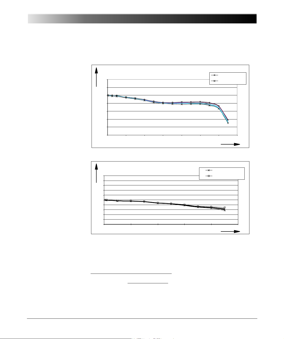
Figure 6-21:
Frequency Response in the 100 V Range
(SR = 28.44 kHz)
-2.5
-2
-1.5
-1
-0.5
0
0.5
1
02468101214
Frequency / kHz
Rel. Erro r / %
Max i mum+3 Si gma max
Min imu m-3 Si gma max
Frequency response in the 100 V range
(SR = 28.44 kHz)
Frequency in kHz
Rel. error in %
Actual - Expected
Full scale
x 100 %Relative error:
(SR = 9.48 kHz)
-1
-0.8
-0.6
-0.4
-0.2
0
0.2
0.4
0.6
0.8
1
012345
Frequency / kHz
Rel. Error / /%
Min imu m-3 Si gma max
Max i mum+3 Si gma max
Frequency response in the 100 V range
(SR = 9.48 kHz)
Frequency in kHz
Rel. error in %
Typical frequency
response with a sampling
rate of 28.44 kHz and an
input voltage of 70 V
1
Technical Data
The accuracy data contains linearity, temperature, long-term drift, and
frequency.
1
Figure 6-22:
Typical frequency
Frequency Response in the 100 V Range
response with a sampling
rate of 9.48 kHz and an
input voltage of 70 V
1
1
a)
b) 3Sigma
The 3Sigma
represents the maximum of the 3Sigma values of all 10 input channels.
max
value of an analog input are determined from 50 measurement values.
max
75
Page 76
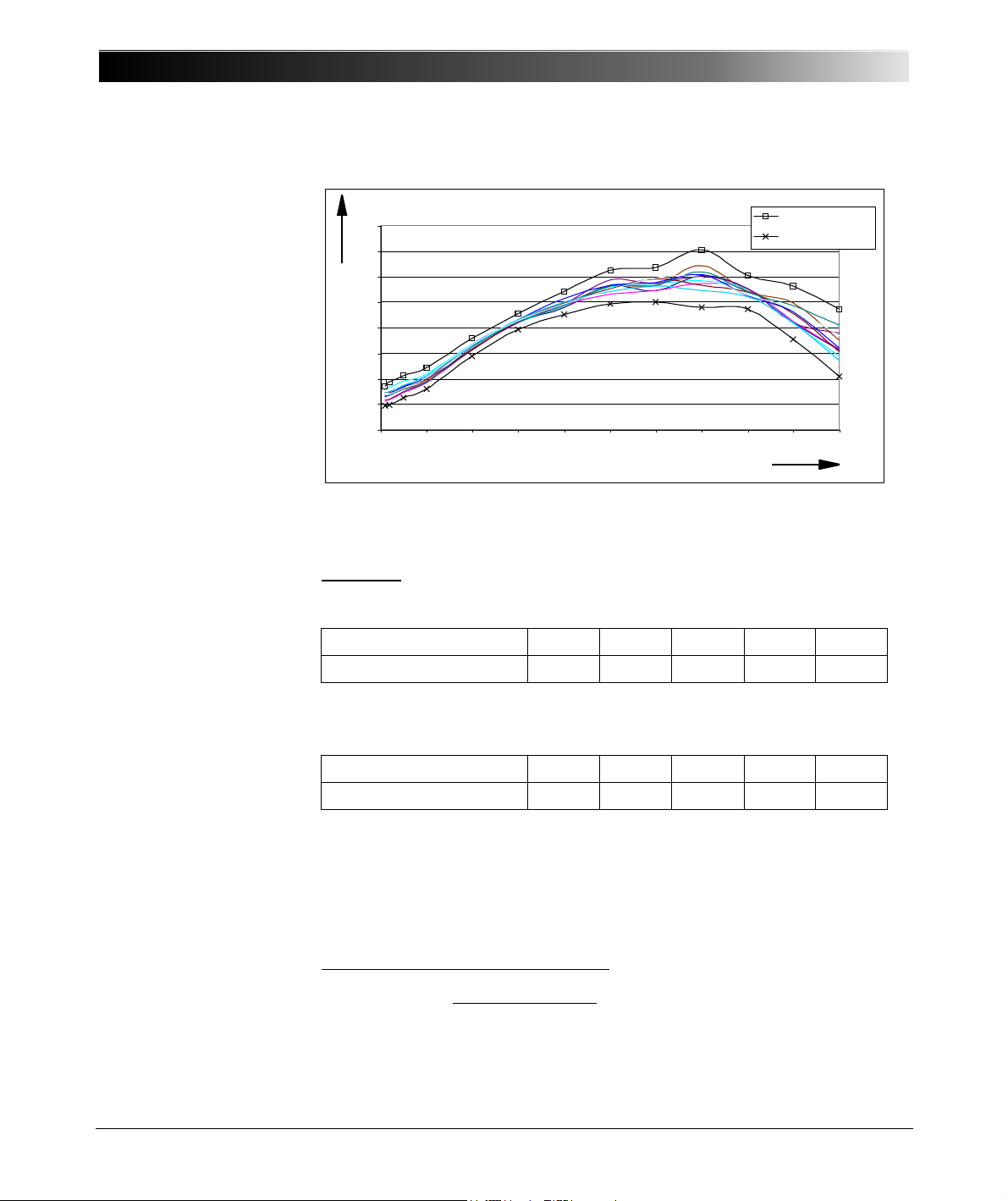
CMC 356 Reference Manual
AC Lin ea rit y in t he 100 V Range
-0.04
-0.03
-0.02
-0.01
0
0.01
0.02
0.03
0.04
0 102030405060708090100
RMS Am plitude / V
Rel. Erro r / %
Max i mum+ 3Si gma max
Min imu m-3 Si gma min
AC linearity in the 100 V range
Amplitude (rms) in V
Rel. error in %
Actual - Expected
Full scale
x 100 %Relative error:
Figure 6-23:
Typical AC linear
progression at 50 Hz and a
sampling rate of
28.44 kHz
1
6.10.6.2 Channel Cross-Talk
Table 6-34:
Cross talk dampening
1
Conditions: sinusoidal form infeed on a channel without overload, AC
measurement on neighboring channel, integration time 1 s.
Measurement range 600 V 100 V 10 V 1 V 100 mV
Dampening in dB 80 105 95 120 120
Cross talk dampening on channels of the same potential groups in dB at
f=50Hz
Table 6-35:
Cross talk dampening
Measurement range 600 V 100 V 10 V 1 V 100 mV
Dampening in dB 65 80 75 95 95
Cross talk dampening on channels of the same potential groups in dB at
f = 500 Hz
The cross-talk dampening on a neighboring channel of another potential
76
group is greater than 120 dB in all measurement ranges (f = 50 Hz or
500 Hz).
1
a)
b) 3Sigma
max
The 3Sigma
represents the maximum of the 3Sigma values of all 10 input channels.
value of an analog input are determined from 50 measurement values.
max
Page 77
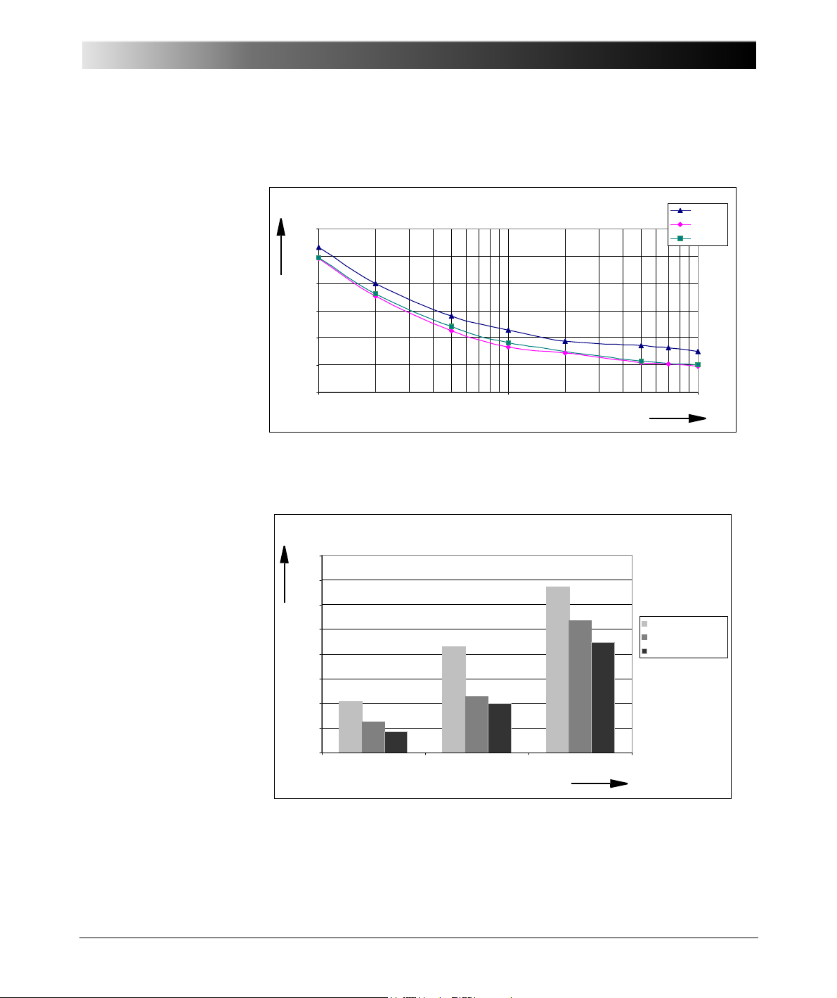
6.10.6.3 Accuracy of Phase Measurement
Phase Error as a Function of the input voltage
(Phase CH1-CH2, Range:100 V, f = 50 Hz)
0
0,05
0,1
0,15
0,2
0,25
0,3
110100
Amplitude CH2 (Vrms )
Phase Error / °
CH1: 10 V
CH1: 70 V
CH1: 50 V
Phase. error in °
Phase error as function of the input voltage
Phase CH1-CH2; range: 100 V; f = 50 Hz
Amplitude CH2 in Vrms
Phase Er ror as function of the s ampling rate
(fin = 50Hz, R:100 V)
0
,
3
3
5
°
0
,
0
6
3
°
0
,
1
1
4
°
0
,
2
6
8
°
0
,
0
4
3
°
0
,
0
9
9
°
0
,
2
2
4
°
0
,
2
1
5
°
0
,
1
0
4
°
0
0,05
0,1
0,15
0,2
0,25
0,3
0,35
0,4
28.44kHz 9.48kHz 3.16kHz
Sampling Rate
Phase Error / °
U = 10Vrms (R:100V)
U = 20Vrms (R:100V)
U = 70Vrms (R:100V
Phase. error in °
Phase error as function of the sampling rate
(fin = 50 Hz, range = 100 V)
Sampling rate
Figure 6-24:
Phase error as function of
input voltage
Technical Data
Conditions: integration time 1 s, measurement signal sinusoidal,
measurement range 100 V, f = 50 Hz, sampling rate 28.44 kHz.
Figure 6-25:
Phase error as function of
sampling rate
Conditions: integration time 1 s, measurement signal sinusoidal, f = 50 Hz,
measurement range 100 V, both channels same excitation (20 V, 70 V).
77
Page 78

CMC 356 Reference Manual
Phase Error as a Function of Frequency
(SR = 28.44 kHz, R: 100 V, Uin = 20 V rm s)
0
0.05
0.1
0.15
0.2
0.25
0.3
0 100 200 300 400 500 600 700 800 900 1000
Frequency / Hz
Phase Error / °
Phase error as function of input frequency
(fs = 28.44 kHz, range = 100 V, Uin = 20 Vrms)
Phase. error in °
Frequency in Hz
Figure 6-26:
Typical phase error as
function of the input
frequency
Conditions: integration time 1 s, measurement signal sinusoidal, sampling
rate = 28.44 kHz, measurement range 100 V, excitation on both channels
20 Vrms.
The maximum input frequency for the phase measurement depends on the
sampling rate.
Table 6-36:
Sampling rate and input
frequency range
Sampling rate Input frequency range
28.44 kHz 10 Hz ... 2.30 kHz
9.48 kHz 10 Hz ... 750 Hz
3.16 kHz 10 Hz ... 250 Hz
Note:
1. The measurement accuracy of phase can be improved by:
• increasing the integration time
• enabling the recursive averaging function
2. When measuring very small phase shifts (less than 0.2 °), the sign
(positive or negative) of the measurement results can not be definitely
determined. If this causes a problem, please refer to the phase
measurement in the harmonic analysis.
3. For measuring phase, the input voltage should be greater than 5 % of full
scale. An overload of the measurement channel does not negatively
affect the obtainable accuracy.
78
Page 79
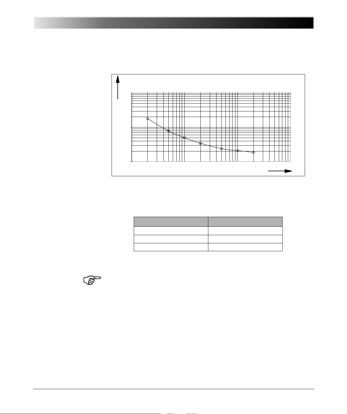
6.10.6.4 Accuracy of Frequency Measurement
Error in Frequency Measur em ent as a Function of the input voltage
(Measured over 50 Periods)
0,001
0,01
0,1
1 10 100 1000
Volt age s ignal in % of full r ange
Rel. Frequency Error / %
Error in frequency measurement as a function of the input voltage
(measured over 50 periods)
Rel. frequency error in %
Voltage signal in % of full range
Figure 6-27:
Error in the frequency
measurement as a
function of the input
voltage
Technical Data
Conditions: integration time 1 s, measurement signal sinusoid.
The maximum input frequency for the frequency measurement depends on
the sampling rate.
Table 6-37:
Sampling rate and input
frequency range.
Sampling rate Input frequency range
28.44 kHz 10 Hz ... 1500 Hz
9.48 kHz 5 Hz ... 500 Hz
3.16 kHz 5 Hz ... 150 Hz
Conditions: Excitation greater than 10 % from measurement full scale, duty
cycle 50 %.
Note: With the harmonic analysis, input frequencies up to 3.4 kHz can be
measured.
79
Page 80
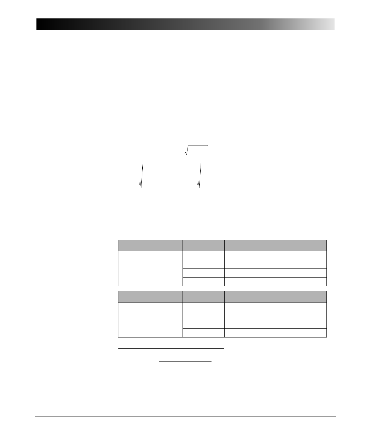
CMC 356 Reference Manual
P
1
T
---=*ut()*it() td
0
T
Q S2P2–= *sign_Q
1
T
--- * ut()
2
td
0
T
1
T
--- * it()
2
td
0
T
Actual - Expected
Full scale
x 100 %Relative error:
6.10.6.5 Accuracy of Power Measurement
General
The power is calculated from one current channel and one voltage channel:
Active power: [W]
x I
Apparent power: S = V
rms
rms
[VA]
Reactive power: [var]
U
= , I
rms
rms
=
Accuracies
Table 6-38:
Sampling rates
28.44kHz
9.48kHz
3.16kHz
Table 6-39:
Sampling rate
28.44kHz
Conditions: integration time 1s, measurement signal sinusoidal, excitation
10-100 %, accuracy references the apparent power, error of the current
clamp is not taken into account.
Frequency range Power Accuracy
1
AC Typical Guaranteed
10 Hz ... 100 Hz S ± 0.3 % ± 0.7 %
P±0.3% ±0.7%
Q±0.8% ±2%
Frequency range Power Accuracy
1
AC Typical Guaranteed
10 Hz ... 2.2 kHz S + 0.3 % / - 1.2 % ± 2.5 %
P + 0.3 % / - 1,2 % ± 2.5 %
Q + 0.8 % / - 2.5 % ± 3.5 %
1
S = Apparent power
P = Active power
Q = Reactive power
80
Page 81
Technical Data
Actual - Expected
Full scale
x 100 %Relative error:
Table 6-40:
Sampling rate
9.48 kHz
Table 6-41:
Sampling rate
3.16 kHz
Table 6-42:
DC accuracy
Frequency range Power Accuracy
1
AC Typical Guaranteed
10 Hz ... 750 Hz S + 0.3 % / - 0.7 % ± 1.8 %
10 Hz ... 750 Hz P + 0.3 % / - 0.7 % ± 1.8 %
10 Hz ... 750 Hz Q + 0.8 % / - 1.2 % ± 2.5 %
Frequency range Power Accuracy
1
AC Typical Guaranteed
10 Hz ... 250 Hz S + 0.3 % / - 0.5 % ± 1.3 %
10 Hz ... 250 Hz P + 0.3 % / - 0.5 % ± 1.3 %
10 Hz ... 250 Hz Q + 0.8 % / - 1 % ± 2.2 %
Power Accuracy
1
DC Typical Guaranteed
P, S ± 0.3 % ± 0.9 %
1
S = Apparent power
P = Active power
Q = Reactive power
Note: The accuracy specifications include linearity, temperature, ageing drift,
frequency and phase response.
81
Page 82
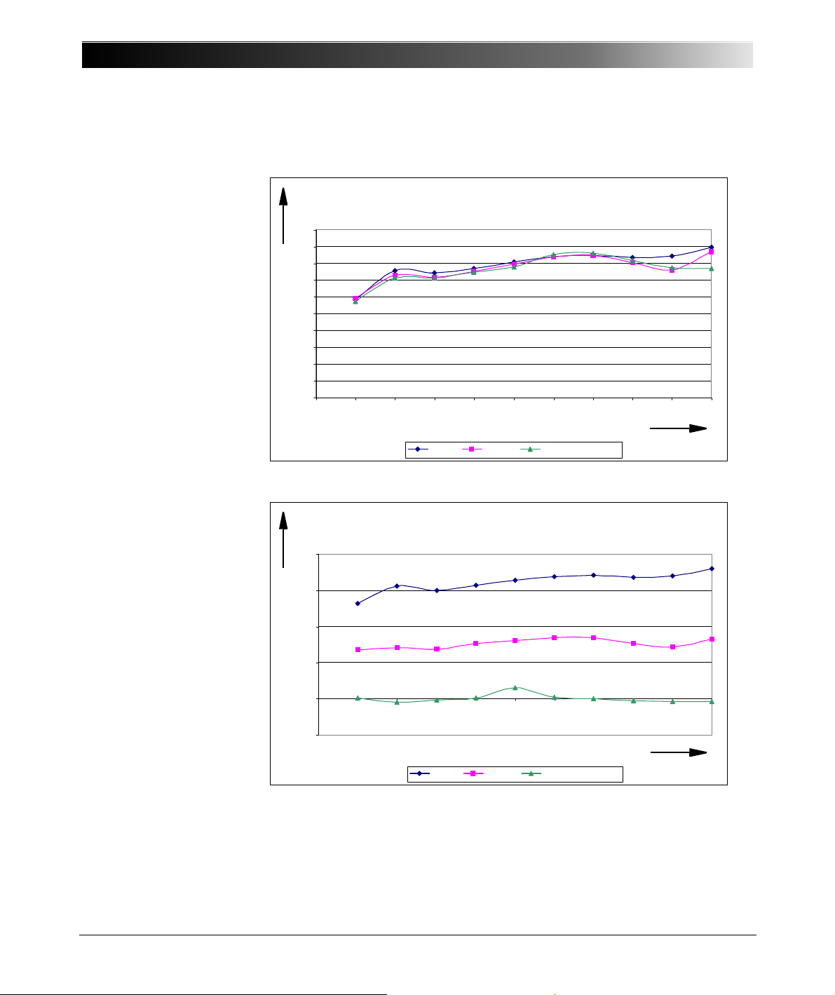
CMC 356 Reference Manual
Typ. Error apparent pow er S as a function of the excitation
(fs = 28.44kHz, f=50Hz)
0
0,02
0,04
0,06
0,08
0,1
0,12
0,14
0,16
0,18
0,2
0 10203040 5060708090100
Excitation CH1&CH2 / %
Rel. Error / %
phi = 1° phi = 60° cos p hi=0.01 (89.4 °)
Typical error of apparent power S as function of the excitation
(fs = 28.44 kHz, f = 50 Hz)
Rel. error in %
Excitation CH1 & CH2 in %
Typ. Err or re al powe r P as a function of the excitation
(fs = 28.44k Hz, f =50Hz)
-0,05
0
0,05
0,1
0,15
0,2
0 1020 30405060708090100
Excitation CH1&CH2 / %
Rel. Error / %
phi = 1° ph i = 60° cos phi=0.01 (89.4°)
Typical error of active power P as function of the excitation
(fs = 28.44 kHz, f = 50 Hz)
Rel. error in %
Excitation CH1 & CH2 in %
Figure 6-28:
Typical error of the
apparent power S as
function of the excitation,
fs = 28.44 kHz, fin = 50 Hz
Typical relative error as function of the excitation
Figure 6-29:
Typical error of the active
power P as a function of
the excitation considering
the apparent power,
fs = 28.44 kHz, fin = 50 Hz
82
Page 83
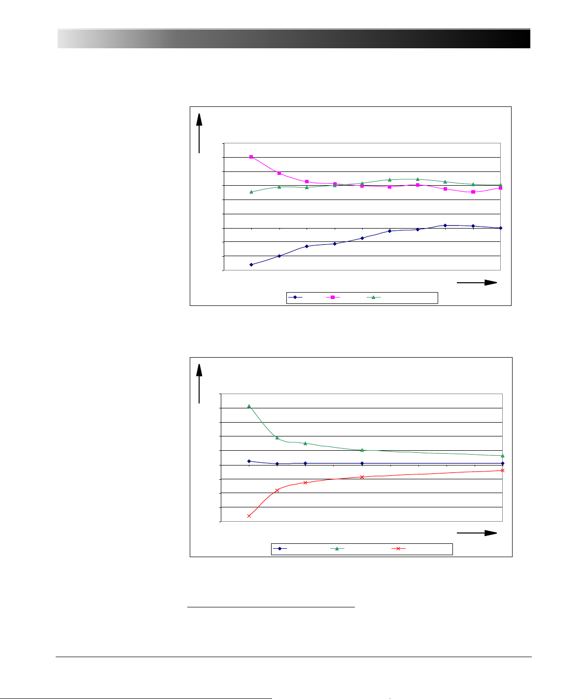
Figure 6-30:
(fs = 28.44kHz, f=50Hz)
-0,15
-0,1
-0,05
0
0,05
0,1
0,15
0,2
0,25
0,3
0 10 2030 405060 708090100
Excitation CH1&CH2 / %
Rel. Error / %
phi = 1° phi = 60° co s ph i=0.01 (89.4°)
Typical error of reactive power Q as function of the excitation
(fs = 28.44 kHz, f = 50 Hz)
Rel. error in %
Excitation CH1 & CH2 in %
Typ. Error reactive power Q as a function of the phas e shift
(fs = 28.44k Hz , f = 50HZ)
-0,4
-0,3
-0,2
-0,1
0
0,1
0,2
0,3
0,4
0,5
0 0,1 0,2 0,3 0,4 0,5 0,6 0,7 0,8 0,9 1
Phas e / °
Rel. Error / %
Average Error Error (+3s igma) Er r or ( - 3s ig m a)
Typical error of reactive power Q as function of the phase shift
(fs = 28.44 kHz, f = 50 Hz)
Rel. error in %
Phase shift in °
Typical error of the
reactive power Q as a
function of the excitation,
fs = 28.44 kHz, fin = 50 Hz
Figure 6-31:
Typical error
1
of the
reactive power Q as a
function of the phase shift
considering the apparent
power, fs = 28.44 kHz,
fin = 50 Hz, excitation
CH1 and CH2 = 70 %.
Technical Data
Typ. Erro r re active power Q as a function of the excitation
Conditions: integration time 1s, measurement signal sinusoid, sampling
rate = 28.44 kHz, fin = 50 Hz
1
Conditions: integration time 1s, measurement signal sinusoidal, sampling
rate = 28.44 kHz, both channels with same excitation 70 %
1
The 3Sigma values are determined from 50 measurement values.
83
Page 84

CMC 356 Reference Manual
6.10.7 Harmonic Analysis
Note:
• For very small phase shifts (< 0,3 °) and small excitation (< 10 %), too
small integration time (< 1 s) or sampling rate 3.16 kHz, the sign of the
reactive power cannot definitely be determined.
• The accuracy of the power measurement depends primarily on the
accuracy of the current clamp (refer to section 9.5, "Current Clamp CPROBE1" on page 112).
This operating mode is designed for measuring stationary signals (e.g., not
sinusoid shaped). The input signal is separated into fundamental and
harmonic waves (Fourier Analysis).
The following items are measured:
• frequency of the fundamental wave
• amplitude of the fundamental and harmonic waves
• phase shifts between the fundamental and harmonic waves (also from
the different channels)
The input signals are captured. Finally, the calculation of the measurement
items is carried out. During this time, the input signal is not taken into
consideration.
84
Page 85
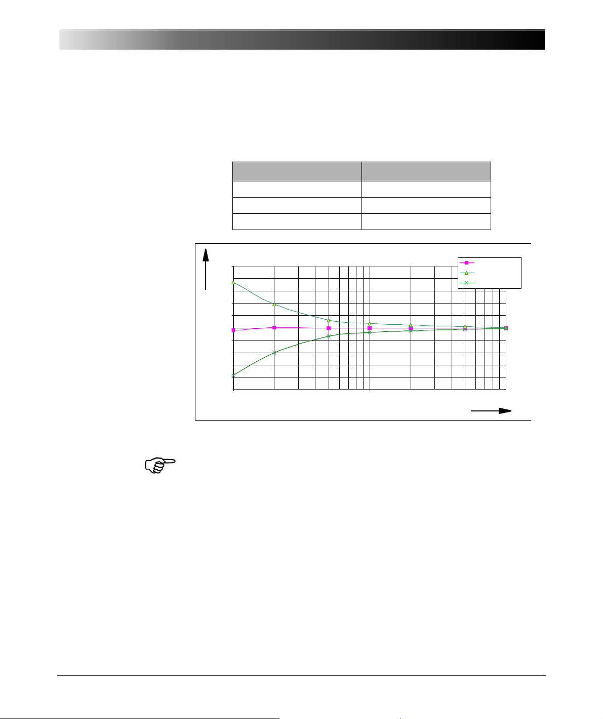
6.10.7.1 Accuracy of Frequency Measurement
Unce rtainty in Freque ncy M easur ement
-0,05
-0,04
-0,03
-0,02
-0,01
0
0,01
0,02
0,03
0,04
0,05
110100
Volt age s ignal in % of full r ange
Frequeny Error / Hz
Average
Av g+3Sigmamax
A v g- 3 Si gma max
Accuracy of frequency measurement
as function of the voltage signal
Frequency error in %
Voltage signal in % of full range
Table 6-43:
Sampling rate and input
frequency range
Figure 6-32:
Accuracy of frequency
measurement as function
of the voltage signal
Technical Data
The permitted input frequency range depends on the specified sampling
rate:
Sampling rate Input frequency range
28.44 kHz 49 Hz ... 3400 Hz
9.48 kHz 17 Hz ... 1100 Hz
3.16 kHz 5 Hz ... 380 Hz
Conditions: sampling rate 9.48 kHz, fin=20 Hz ... 1 kHz
Note: Through recursive averaging, the measurement uncertainty can be
further reduced.
85
Page 86
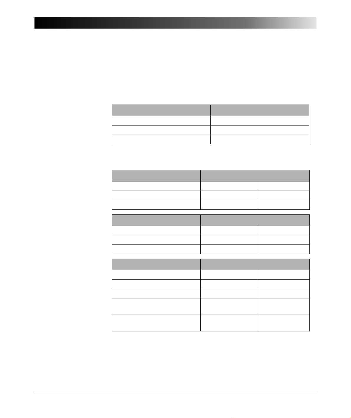
CMC 356 Reference Manual
6.10.7.2 Accuracy of Amplitude Measurement
Table 6-44:
Sampling rate and input
frequency range
Table 6-45:
Sampling rate 28.44 kHz,
measurement range
600 V, 100 V, 10 V, 1 V
Table 6-46:
Sampling rate 28.44 kHz,
measurement range
100 mV
Table 6-47:
Sampling rate
9.48 kHz
3.16 kHz,
measurement range
600 V, 100 V, 10 V, 1 V
The measurement values are given as effective values (rms).
The permitted input frequency range for the fundamental wave depends on
the specified sampling rate:
Sampling rate Input frequency range
28.44 kHz 100 Hz (= fmin) ... 3200 Hz
9.48 kHz 30 Hz (= fmin) ... 1000 Hz
3.6 kHz 10 Hz (= fmin) ... 350 Hz
Valid for fundamental and harmonic waves in specified frequency range; accuracy
refers to full scale.
Frequency range Accuracy
Typical Guaranteed
fmin ... 1 kHz ± 0.1 % ± 0.3 %
fmin ... 10 kHz + 0.1 % / - 0.7 % ± 1.1 %
Frequency range Accuracy
Typical Guaranteed
fmin ... 1 kHz ± 0.2 % ± 0.5 %
fmin ... 10 kHz + 0.2 % / - 1.0 % ± 2.0 %
Frequency range Accuracy
Typical Guaranteed
fmin ... 100 Hz ± 0.1 % ± 0.3 %
fmin ... 1 kHz + 0.1 % / - 0.5 % ± 0.8 %
fmin ... 4 kHz
+ 0.1 % / - 0.8 % ±1.2 %
(sampling rate = 9.48 kHz)
fmin ... 1.4 kHz
+ 0.1 % / - 0.8 % ±1.2 %
(sampling rate = 3.16 kHz)
86
Page 87
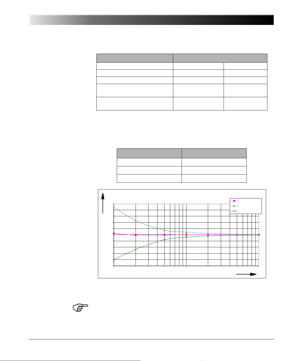
Table 6-48:
Uncer tain ty p has e m e asu re me nt as a f unct ion of Excitatio n
(fs =9.48 kHz, fin=50 Hz)
-2.5
-2
-1.5
-1
-0.5
0
0.5
1
1.5
2
2.5
110100
Excitation / %
Phase Error / °
Average
Av g+3Sigmamax
A v g- 3 Sig ma max
Accuracy of phase measurement
as function of the excitaiton
Phase error in °
Excitation in %
Sampling rate
9.48 kHz
3.16 kHz
measurement range
100 mV
6.10.7.3 Accuracy of Phase Measurement
Table 6-49:
Sampling rate and input
frequency range
Table 6-50:
Accuracy of phase
measurement as function
of the excitation
Technical Data
Frequency range Accuracy
Typical Guaranteed
fmin ... 100 Hz ± 0.15 % ± 0.4 %
fmin ... 1 kHz ± 0.2 % / - 0.5 % ± 0.8 %
fmin ... 4 kHz
+ 0.2 % / - 1.0 % ± 1.5 %
(sampling rate = 9.48 kHz)
fmin ... 1.4 kHz
+ 0.25 % / - 1.0 % ± 2.0 %
(sampling rate = 3.16 kHz)
The permitted input frequency range for the fundamental wave depends on
the specified sampling rate:
Sampling rate Input frequency range
28.44 kHz 100 Hz ... 3200 Hz
9.48 kHz 30 Hz ... 1000 Hz
3.16 kHz 10 Hz ... 350 Hz
Conditions: sampling rate 9.48 kHz, fin = 50 Hz.
Note: Through recursive averaging, the measurement uncertainty can be reduced
further.
87
Page 88
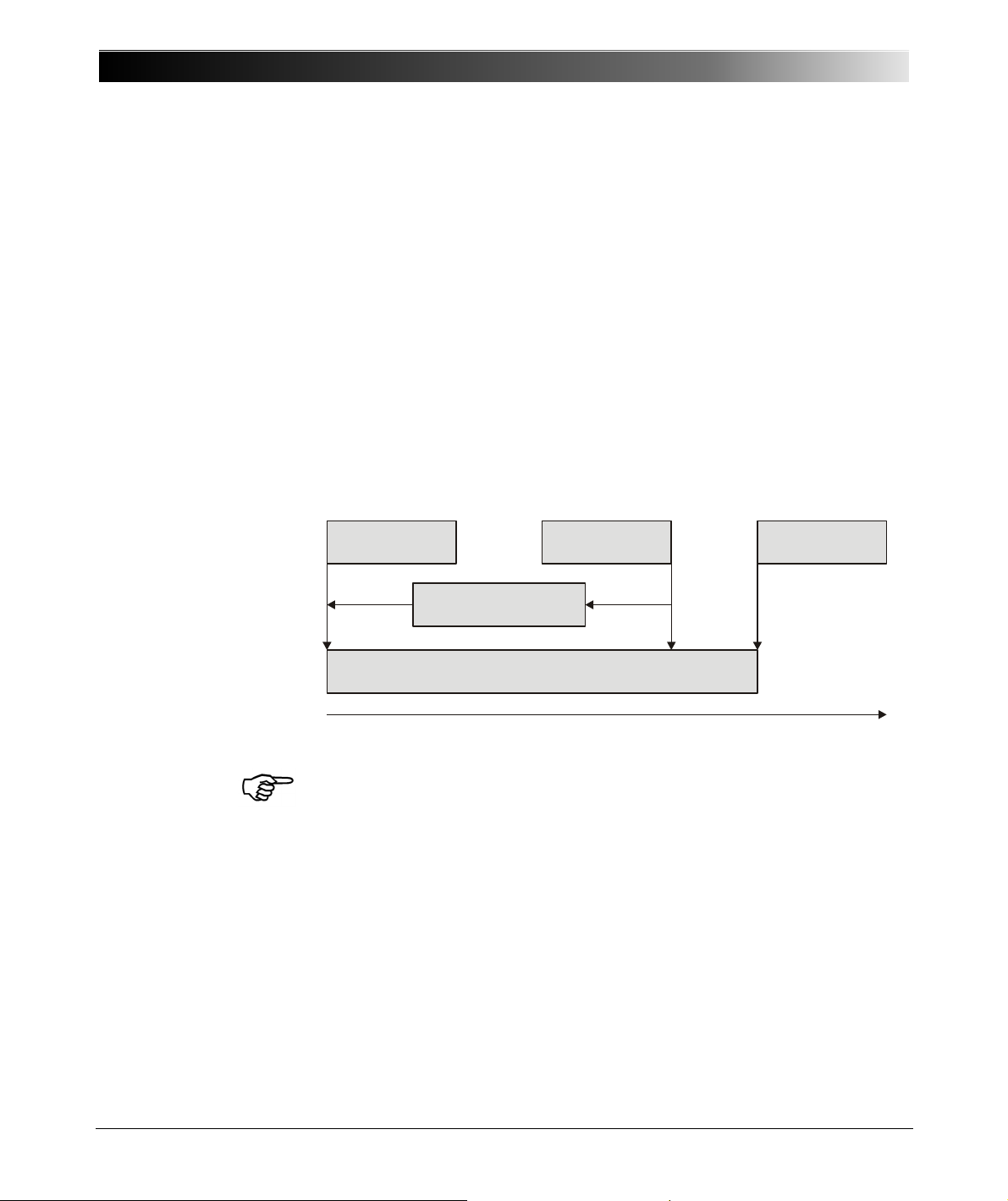
CMC 356 Reference Manual
Start time for
recording
Trigger event
End of
recording
Trigger delay (negative)
Recording of input signals
6.10.8 Transient Recording
Figure 6-33:
Illustration of the
relationship between
trigger events, trigger
delay, and recording time
In this operating mode, transient signals on up to 10 input channels can be
recorded synchronously.
The recording starts whenever a pre-defined trigger condition is met. The
selectable trigger conditions are:
• Trigger on threshold with positive or negative edge
• Combination of different power quality triggers (sag, swell, harmonic,
frequency, frequency change, notch)
In addition, a time offset for the capture window relative to the trigger event
can be specified. The trigger delay can be
• positive (recording begins after the trigger event)
• or negative (recording begins already before the trigger event).
88
Note: More details about triggering methods can be found in the OMICRON
Test Universe Help and in the practical examples of the ELT-1 option.
The maximum length of the recording depends on the settings for the
sample rate and the number of channels to be captured.
Page 89
Table 6-51:
The maximum recording
time depends on the
number of active channels
and the sampling
frequency
Number of
active
channels
Maximum
recording time [s]
at fs = 28.4 kHz
Maximum
recording time [s]
at fs = 9.48 kHz
Maximum
recording time [s]
at fs = 3.16 kHz
1 35.16 s 105.47 s 316.41 s
2 17.58 s 52.73 s 158.20 s
3 11.72 s 35.16 s 105.47 s
4 8.79 s 26.37 s 79.10 s
5 7.03 s 21.09 s 63.28 s
6 5.86 s 17.58 s 52.73 s
7 5.02 s 15.07 s 45.20 s
8 4.40 s 13.18 s 39.55 s
9 3.91s 11.72s 35.15s
10 3.52 s 10.55 s 31.64 s
1
11
3.20 s 9.59 s 28.76 s
Technical Data
1
All binary inputs are stored as one channel.
Accuracy of the sampling value:
• measurement ranges 600 V, 100 V, 10 V, 1 V:
± 0.2 % typical
± 0.5 % guaranteed
• measurement range 100 mV:
± 0.3 % typical
± 0.6 % guaranteed
The accuracy data are full scale errors.
6.10.9 Trend Recording
In Trend Recording Mode, you can make a historical plot of various
measurements over time. It is possible to measure RMS voltage, RMS
current, phase, real, apparent and reactive power and the power factor.
The main view has a CTS Chart. Each selected measurement function
appears in a separate diagram (i.e. all frequency measurements in the
frequency diagram). RMS current and voltage appear in separate diagrams.
Time is displayed in seconds on the x-axis. The diagram is scrolled from
right-to-left as new data is recorded.
89
Page 90

CMC 356 Reference Manual
LL out 7 - 12
6.11 Option LLO-2 (Low Level Outputs)
The LLO-2 option ("LL out 7 - 12") represents an additional SELV
(SELV = S
independent generator triples. These six high accuracy analog signal
sources can serve to either control an external amplifier or to directly
provide small signal outputs.
The outputs 7-12 extend the low level outputs 1-6 ("LL out 1-6") by two more
independent generator triples. Outputs 7-12 are technically identical to
outputs 1-6.
For more information please refer section 6.3.5, "Low Level Outputs "LL out"
for External Amplifiers" on page 52.
afety Extra Low Voltage) interface connector holding two
90
Page 91
Increasing the Output Power, Operating Modes
7INCREASING THE OUTPUT POWER,
OPERATING MODES
The CMC 356 has a very large application diversity. The current outputs
offer enough output power to test all electromechanical relays.
In particular, the CMC 356 offers a variety of types of single-phase operation
using its two galvanically separated three-phase current outputs with which
the output power from the units can be significantly increased.
In cases when the current or the output power - or even the number of
independent voltages or currents - is insufficient, it is possible to switch
individual amplifier groups of the CMC 356 in parallel or to connect external
amplifiers (up to six independent additional channels) to the "LL out 1-6".
The option "LLO-2" extends the low level outputs by two more independent
generator triples “LL out 7-12” (refer to section 6.11, "Option LLO-2 (Low
Level Outputs)" on page 90).
The operating modes illustrated in the following sections can be set in the
Hardware Configuration of the OMICRON Test Universe software.
7.1 Safety Instructions for High Current Output
Observe the following safety instructions when using the operating modes
and connection methods described in this chapter.
• For currents greater than 25 A, the test object (load) should be
exclusively connected to the 4 mm/0.16 " banana sockets and not to the
generator combination socket.
• Since a current of 32 A flowing through a test lead (2 m/6 ft. legth,
2.5 mm
connection methods shown in this chapter.
• When connecting current outputs in parallel, it has to be ensured that the
test leads are only connected together immediately at the test object and
that the test leads have sufficient diameter.
• At maximum amplitude of the 128 A mode, the cable losses can amount
to 112 W for AC and 280 W for DC operation.
• At maximum amplitude of the 64 A mode, the cable losses can amount
to 28 W for AC and 140 W for DC operation.
• For applications drawing DC current: The test object (load) should be
exclusively non-inductive! Note that a load of, for example, 1 Henry can
store 50 J (Joule) at 10 A DC for a long period of time. Electrical shocks
with more than 350 mJ can be life-hazardous for the user.
2
) causes a loss of 15 ... 18 W, we recommend to use the
91
Page 92
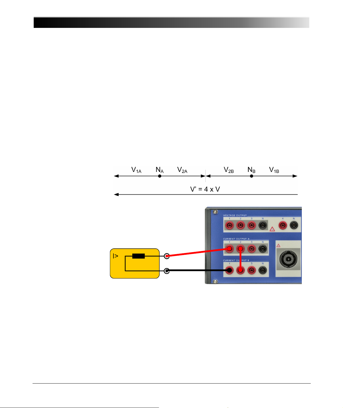
CMC 356 Reference Manual
Load
1’
N’
7.2 Single-Phase Operation of the CMC 356
7.2.1 1 x 32 A High Burden Mode (L-L-L-L)
Figure 7-1:
Single-phase operation,
1 x 32 A high burden mode
1 x 0 ... 32 A (±45 ADC), max. 140 V
, 1 x 1740 VA at 25 A
peak
Both amplifier groups CURRENT OUTPUT A and CURRENT OUTPUT B
are connected in series. The currents 1 and 2 of a group are phaseopposite. This results in four times the compliance voltage of a single
output.
Observe the safety instructions given in Section 7.1 on page 91 when using
this operating mode.
Refer to the output curves shown in the figures 6-1 through 6-5 in section
6.3.2, "Current Outputs" on page 43.
92
Page 93
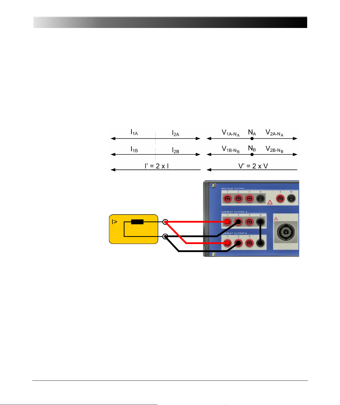
Increasing the Output Power, Operating Modes
Load
1’
N’
7.2.2 1 x 64 A High Burden and High Current Mode (L-L)
Figure 7-2:
Single-phase operation,
1 x 64 A high burden and
high current mode
1 x 0 ... 64 A (±90 ADC), max. 70 V
, 1 x 1740 VA at 50 A
peak
The currents 1 and 2 of each group are phase-opposite. In addition, the
groups A and B are connected in parallel.
Observe the safety instructions given in Section 7.1 on page 91 when using
this operating mode.
Refer to the output curves shown in the figures 6-1 through 6-5 in section
6.3.2, "Current Outputs" on page 43.
93
Page 94
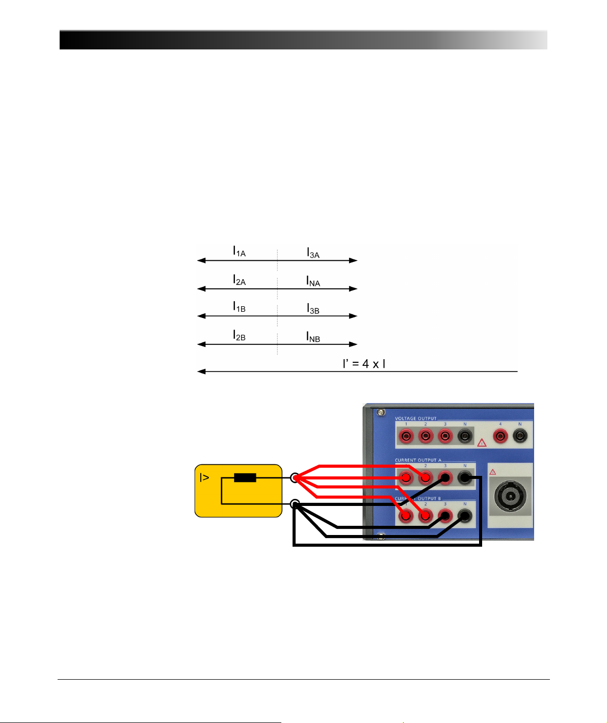
CMC 356 Reference Manual
Load
1’
N’
7.2.3 1 x 128 A High Current Mode (LL-LN)
Figure 7-3:
Single-phase operation,
1 x 128 A high current
mode
1 x 0 ... 128 A (±180 ADC), max. 35 V
Since the current over the N socket is limited to 32 A
, 1 x 1000 VA at 80 A
peak
rms
(45 ADC), the third
phase is used to support the N socket. The currents 1, 2 of groups A and B
are connected in parallel.
Observe the safety instructions given in Section 7.1 on page 91 when using
this operating mode.
Refer to the output curves shown in the figures 6-1 through 6-5 in section
6.3.2, "Current Outputs" on page 43.
94
Page 95
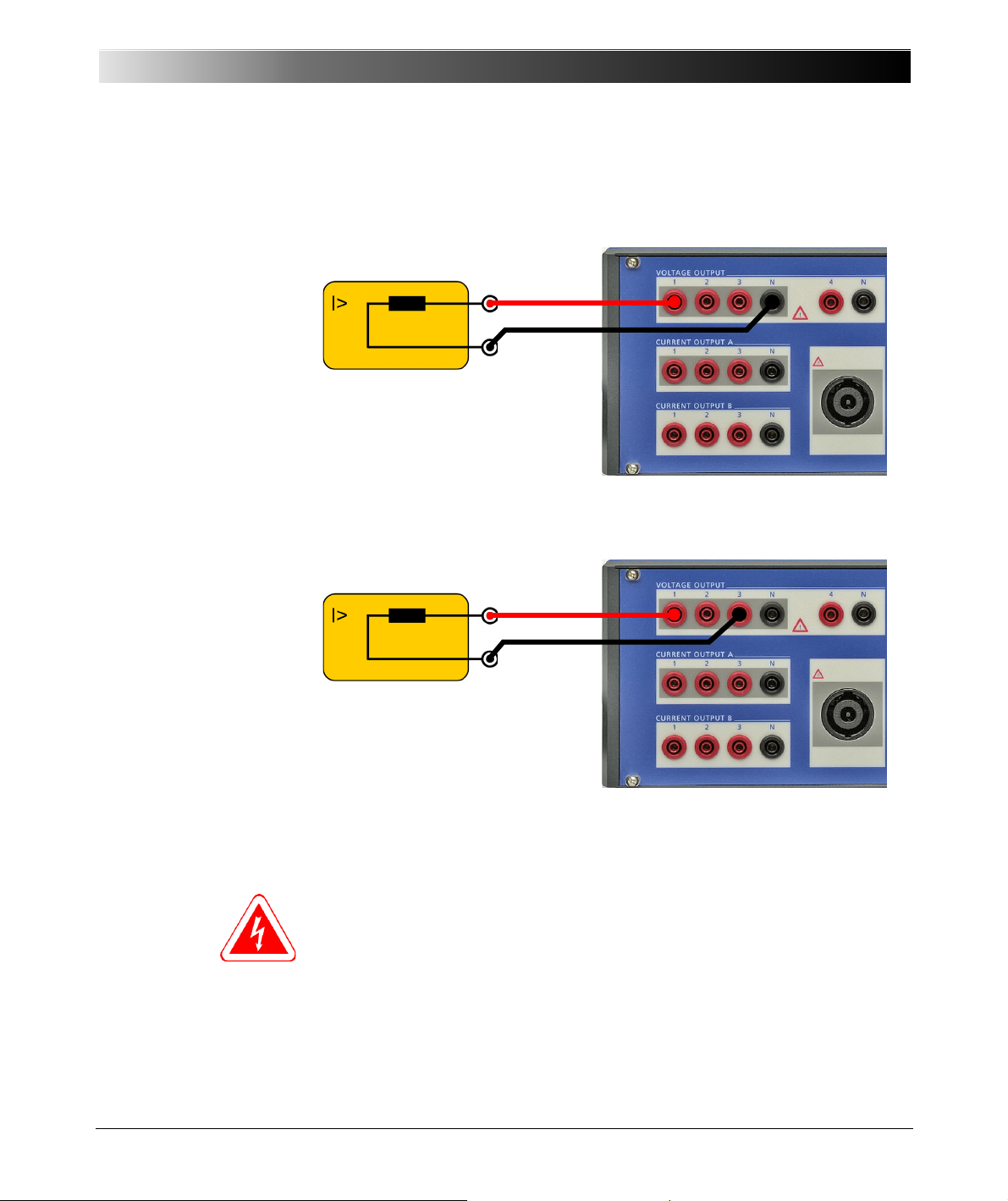
7.2.4 Single-Phase Voltage
Load
1’
N’
Load
1’
N’
Figure 7-4:
Single-phase operation of
the voltage system (L-N)
Figure 7-5:
Single-phase operation of
the voltage system
(L-L phase opposition)
Increasing the Output Power, Operating Modes
1 x 0 ... 300 V, 1 x 200 VA [100 ... 300 V] typical
1 x 0 ... 600 V, 1 x 275 VA [200 ... 600 V] typical
Refer to the output curves shown in the figures 6-8 through 6-9 in section
6.3.3, "Voltage Outputs" on page 48.
Note: Never connect N’ or any other phase to GND (PE). This can cause
life-hazardous
situations to persons and damage to property.
95
Page 96
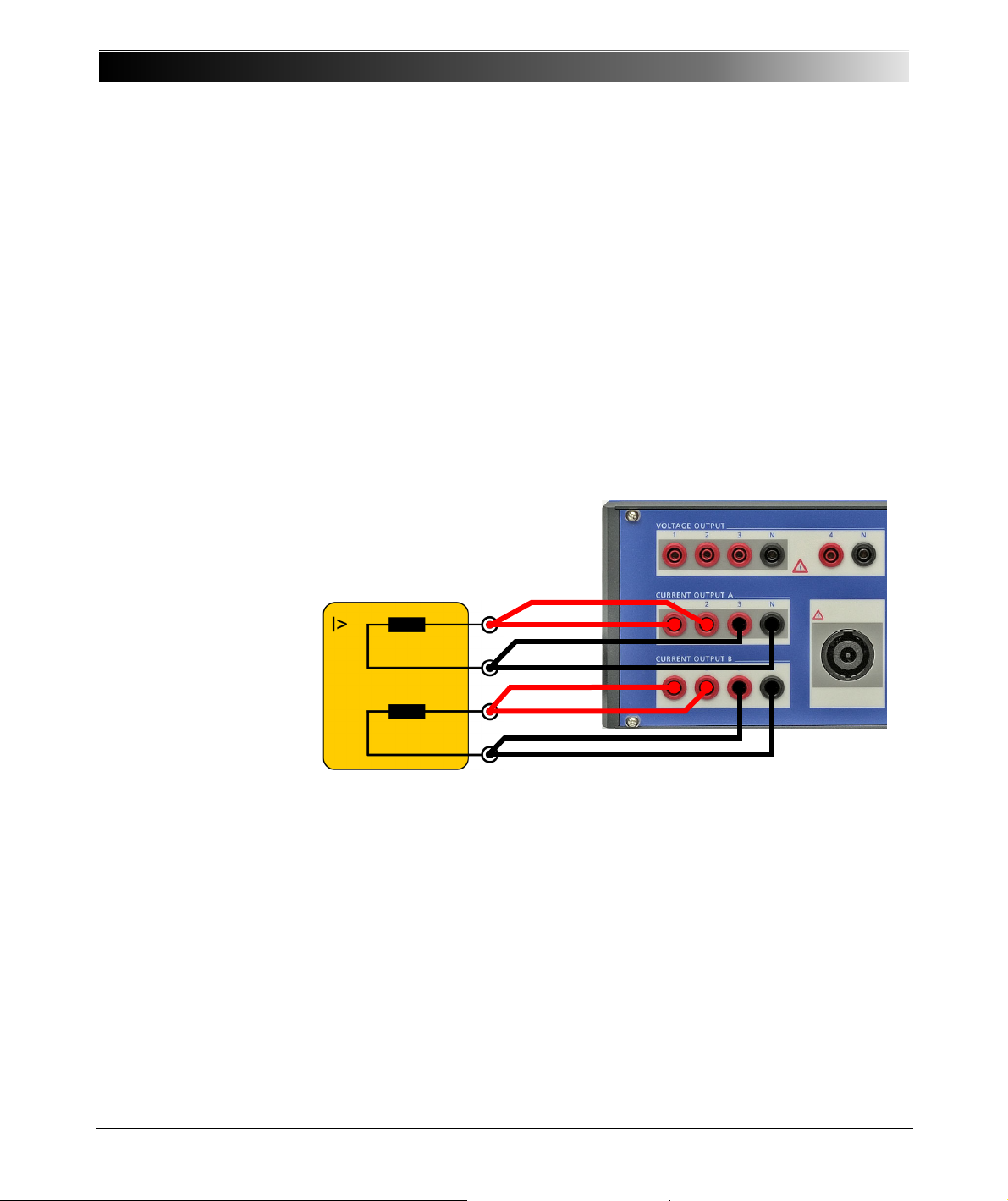
CMC 356 Reference Manual
Load
1’
N
1
’
2’
N
2
’
7.3 Two-Phase Operation
7.3.1 2x64A High Current Mode (LL-LN)
For some applications it is beneficial to have two independent currents,
each higher than 32 A
, or a higher compliance voltage available.
rms
Figure 7-6:
Two-phase operation,
2 x 64 A high current mode
2 x 0 ... 64 A (±90 ADC), max. 35 V
Since the current over the N socket is limited to 32 A
, 2 x 500 VA at 40 A
peak
(45 ADC), the third
rms
phase is used to support the N socket.
Observe the safety instructions given in Section 7.1 on page 91 when using
this operating mode.
96
Page 97
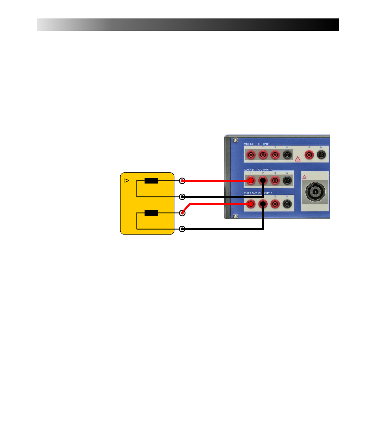
Increasing the Output Power, Operating Modes
Load
1’
N
1
’
2’
N
2
’
7.3.2 2 x 32 A High Burden Mode (L-L)
Figure 7-7:
Two-phase operation
2 x 32 A high burden mode
2 x 0 ... 32 A (±45 ADC), max. 70 V
, 2 x 870 VA at 25 A
peak
The currents 1 and 2 of each group are phase-opposite.
Observe the safety instructions given in Section 7.1 on page 91 when using
this operating mode.
97
Page 98
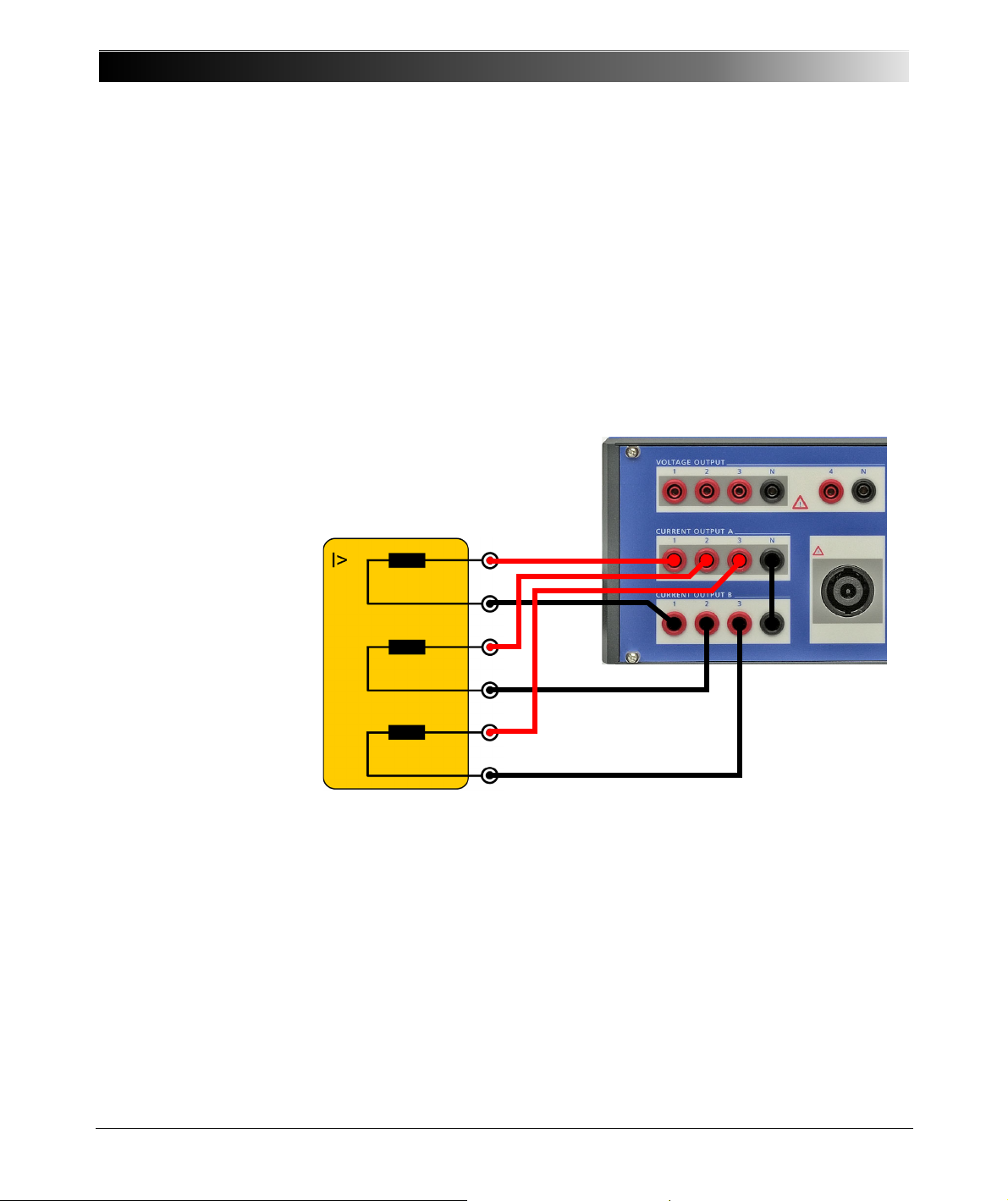
CMC 356 Reference Manual
Load
1’
N
1
’
2’
N
2
’
3’
N
3
’
7.4 Three-Phase Current Mode with High Burden
Figure 7-8:
Three-phase operation
3 x 0 ... 32 A (±45 ADC), max. 70 V
, 3 x 860 VA at 25 A
peak
For loads with three separate phases it is possible to double the available
compliance voltage. However, this configuration does not make sense, if a
common N connector is required! Do not connect N1, N2 and N3 to each
other!
Observe the safety instructions given in Section 7.1 on page 91 when using
this operating mode.
98
Page 99

Increasing the Output Power, Operating Modes
7.5 Operation with External Amplifiers
The connections "LL out 1-6" offer a large variety of extension possibilities.
They enable the connection of external amplifiers in order to increase the
number of independent voltage or current channels and thus provide the
possibility to realize additional applications the CMC 356 alone cannot
cover.
Each LL output socket ("LL out 1-6" and the optional "LL out 7-12") can
connect up to four external amplifiers with six independent channels.
The following configurations are possible:
•9×25A
/ 70 VA for differential relays in three galvanically separated
rms
current triples with CMC 356 + CMA 156.
• 6 × 250 V / 75 VA for the synchronization in two galvanically separated
voltage triples with CMC 356 + CMS 156.
For a complete overview of the supported configurations of the CMC 356
and CMA/S amplifiers see the OMICRON Tes t Uni v ers e Help, topic
Hardware Configuration.
99
Page 100

CMC 356 Reference Manual
100
 Loading...