

OMEX OMEM710 Hardware Manual
OMEM710 Hardware Manual 2v11
1
Hardware Manual
OMEM710
www.omextechnology.com
710 Series ECU

OMEM710 Hardware Manual 2v11
2

OMEM710 Hardware Manual 2v11
3
1 Introduction ................................................................................................................. 6
1.1 Notation Used in This Manual .................................................................................. 6
2 Setup Procedure ......................................................................................................... 7
3 Software ...................................................................................................................... 9
4 Inputs and Outputs ................................................................................................... 10
4.1 Ignition Coils ........................................................................................................... 10
4.2 Fuel Injector ............................................................................................................ 10
4.3 PWM Devices ......................................................................................................... 10
4.4 Switch Outputs ....................................................................................................... 11
4.5 Switch inputs .......................................................................................................... 12
5 Sensor Setup ............................................................................................................ 13
5.1 Throttle Position Sensor ......................................................................................... 13
5.2 MAP Sensor ........................................................................................................... 13
5.3 MAF Sensor ........................................................................................................... 14
5.4 Coolant Temperature Sensor ................................................................................. 14
5.5 Air Temperature sensor .......................................................................................... 15
5.6 Barometric Pressure ............................................................................................... 16
5.7 Road Speed Sensor ............................................................................................... 16
5.8 Crank Sensor ......................................................................................................... 17
5.9 Trigger Wheel ......................................................................................................... 18
5.10 Cam1 Sensor ......................................................................................................... 20
5.11 Cam2 Sensor ......................................................................................................... 21
5.12 Ignition Timing Alignment ....................................................................................... 21
6 Map Axes ................................................................................................................... 23
6.1 Engine Speed ......................................................................................................... 23
6.2 Engine Load ........................................................................................................... 23

OMEM710 Hardware Manual 2v11
4
7 Basic Fuel Setup ...................................................................................................... 26
7.1 Battery Voltage Compensation............................................................................... 27
8 Rev Limits ................................................................................................................. 30
9 Dashboard ................................................................................................................. 31
9.1 Tacho ..................................................................................................................... 31
9.2 Shift Light ............................................................................................................... 31
9.3 Gear dependent shift light speed ........................................................................... 31
10 Engine Start Condition ............................................................................................. 32
10.1 Ignition ................................................................................................................... 32
10.2 Fuel ................................................................................................ ........................ 32
11 Idle Strategies ........................................................................................................... 34
11.1 Without air bypass idle motor ................................................................................. 34
11.2 With air bypass idle motor ...................................................................................... 35
12 Transient Conditions................................................................................................ 39
12.1 Acceleration Fuel ................................................................................................... 39
12.2 Deceleration Fuel Cut Off ....................................................................................... 41
13 Conditions Corrections............................................................................................ 42
13.1 Coolant Temperature ............................................................................................. 42
13.2 Air Temperature ..................................................................................................... 42
13.3 Barometric Pressure .............................................................................................. 43
13.4 Individual Fuel Output Trims .................................................................................. 43
14 Cold Engine Running ............................................................................................... 44
15 Oxygen Feedback ..................................................................................................... 45
15.1 Narrowband ........................................................................................................... 45
15.2 Wideband ............................................................................................................... 48

OMEM710 Hardware Manual 2v11
5
16 Cooling Fans ................................................................ ................................ ............. 49
17 Knock Control ........................................................................................................... 50
18 Full Throttle Gearshift .............................................................................................. 51
19 Staged Injectors ........................................................................................................ 54
19.1 Twin Injectors ......................................................................................................... 54
19.2 Staged Injectors ..................................................................................................... 54
20 VTEC Cam Control .................................................................................................... 55
21 VVC Cam Control ...................................................................................................... 56
22 Turbo Boost Control ................................................................................................. 57
23 Anti-lag ...................................................................................................................... 58
24 Alt Function ............................................................................................................... 59
25 User1 .......................................................................................................................... 60
26 Internal Data Logging ............................................................................................... 61
27 Ignition Dwell Control ............................................................................................... 62
28 Security ..................................................................................................................... 63
29 Wiring ........................................................................................................................ 65
29.1 Semi Assembled Loom Construction ..................................................................... 65
29.2 ECU Connector Pins .............................................................................................. 66
29.3 Component Pin-outs ............................................................................................... 67
29.4 Diagrams ................................................................................................................ 68

OMEM710 Hardware Manual 2v11
6
Thank you for choosing Omex Engine Management. This manual is written to help the user through
the specifics of the OMEM710 ECU. It is essential that the user reads all of the Omex manuals
before attempting to install the system and before attempting to start the engine. Incorrect use
of the Omex system could potentially lead to damage to the engine and personal injury. If you have
any doubts about fitting these parts or using the software then please contact Omex for help.
As the system is computer based, technical support is given on the assumption that the user is able
to perform simple Windows based operations. The user will also need access to email as Omex will
nearly always require a copy of the map in the ECU to give support.
Omex may not be held responsible for damage caused through following these instructions,
technical, or editorial errors or omissions. If you have any doubts about fitting these parts or using
the software then please contact Omex for help.
1.1 Notation Used in This Manual
Menu commands are signified in bold type with a pipe symbol | between each level of the menu.
For example, File | Open indicates that you should click on the Open option in the File menu.
UPPER CASE TEXT is used to indicate text that should be typed in by the user.
1 Introduction

OMEM710 Hardware Manual 2v11
7
Wiring
Wire your semi-assembled harness or ready-built harness as shown in the Wiring section of this
manual.
Trigger Wheel
If installing a trigger wheel of missing tooth type,
Accurately mark TDC.
Turn the engine to approximately 90o BTDC.
Mount your crank position sensor (CPS) anywhere around the perimeter of the timing wheel
pointing towards the centre of the wheel with a sensor to wheel gap of approximately 0.5mm.
Mount the trigger wheel with the missing tooth pointing at the sensor.
If machining a trigger pattern into the front pulley then it is usually easiest to machine all of the teeth
in, mount the front pulley, and then remove the tooth pointing at the sensor at 90o BTDC.
Software
Follow the ‘Software’ chapter of this manual for instructions on how to connect to your ECU and
send your startup calibration.
Setup before mapping
Follow the ‘Auxiliary Inputs and Outputs’ chapter, though we suggest that all non-essential functions
(e.g. full throttle gearshift) are disabled until fuel and ignition mapping is complete.
Follow the ‘Sensor Setup’ chapter.
Follow the ‘Rev Limits’ chapter.
Follow the ‘Map Axes’ chapter (advanced users only).
For many engine configurations, the majority of these sections can be ignored as the start-up
calibration will be set to suit the standard engine. Refer to the calibration’s notes field for information
about sensors used in the calibration.
First start fuel
When attempting to start the engine for the first time you may need to change the injector scaling as
the fuel requirements, injector flowrates, and fuel pressure vary between engines. The option
Microsec/bit is a linear scaling factor. A higher number is more fuel, a lower number is less.
First start ignition timing
Follow the ‘Ignition Timing Alignment’ section of the ‘Sensor Setup’ chapter.
Main fuel and ignition mapping
Ensure before mapping that the oxygen feedback is disabled by setting Standard | OX FB | OX FB
Rate = 0.
If a road car, calibrate the injector battery voltage offsets before much mapping is done.
Map all fuel and ignition in steady state conditions.
Calibrate warm running transient fuel.
2 Setup Procedure

OMEM710 Hardware Manual 2v11
8
Calibrate warm engine starting fuel.
Cold starting / running setup
It is important to calibrate the cold running in the correct order as some of the tables are in effect all
of the time and so will affect the results of others.
Start engine from cold however you can (ignoring the cold cranking fuel for now), and calibrate the
Coolant Fuel trim table and the Accel Coolant trim table. The Coolant fuel trim table is used for
steady-state engine running, and the Accel Coolant trim table for increased acceleration fuel whilst
cold. Refer to the relevant sections for further advice on this.
When the cold running is complete, you can calibrate cold starting. Refer to the relevant section for
advice on this.

OMEM710 Hardware Manual 2v11
9
Installing the software
Run SetupMAP4000.x.xx.xx.exe and follow the onscreen instructions.
Connection port
The ECU requires an RS232 serial connection. Desktop PCs and older laptops will have 9pin D
shaped ports on them marked COM for this type of communication. If you have this port then this is
the best to use for communication with the ECU. If your PC does not have one of these ports then
you will need to use an adapter. We suggest using the USB to RS232 adapter from ‘ATEN’ as the
software has been specifically designed for this adapter.
Connecting to the ECU
Ensure that if you are using an adapter, the drivers software from the adapter manufacturer has
been installed.
Join the data lead between the ECU and the PC
Open MAP4000 from the ‘Start bar’
Go to ECU | Connection Setup and select your port from the list
ECU | Connect
Ignition ON (do not crank the engine)
The ‘Receiving Calibration’ bar will start moving across. When completed, you are connected to
the ECU.
Sending the startup calibration to the ECU
It is not possible to start a new calibration from File | New. Please contact Omex for a
suitable start-up calibration.
Save the start-up calibration from the start-up disk or email to the hard-drive in the location
Documents\OMEX\MAP4000\Calibrations. (note that this folder is only created when MAP4000
is opened for the first time so you must have opened MAP4000 on this PC before)
Connect to the ECU as described in the above section.
ECU | Send new calibration
Ignition ON (do not crank the engine)
Select your start-up calibration and press ‘open’
When the calibration has been sent to the ECU cycle ignition power OFF / ON
3 Software
OMEM710 Hardware Manual 2v11
10
The physical input and output pins for each function are in some cases fixed (eg Coolant
Temperature sensor must always be on the same physical pin) but many are selectable. The
physical pins have names based on their normal output type, but the names do not necessarily tell
the user what they are being used as. The wiring section of the manual gives suggested pin-outs for
most engines but some will need to be decided by the user. If you are in any doubt then please
contact Omex. The ECU needs to be told which pins are being used for which functions. Much of
this will be set in startup calibrations from Omex.
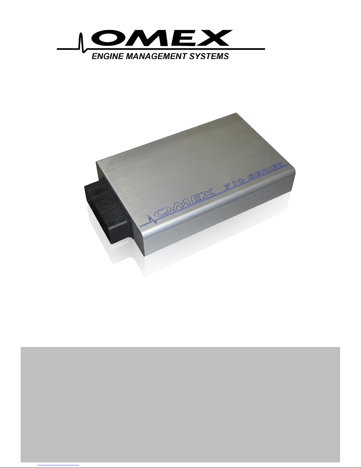
4.1 Ignition Coils
Ignition coils may be controlled on any of the IGN pins. To set an IGN pin as a coil driver it must
have the IGNx and TOCx ON.
4.2 Fuel Injector
Injectors may be controlled by any of the FUEL pins and IGN3, IGN4, IGN5, or IGN6.
To set a FUEL pin as an injector driver it must have the FUELx as injector ON and FUELx as PWM
OFF.
To set IGN3, IGN4, IGN5, or IGN6 pin as an injector driver they must have the TOCx and IGNx as
FUELx ON. IGNx must be OFF.
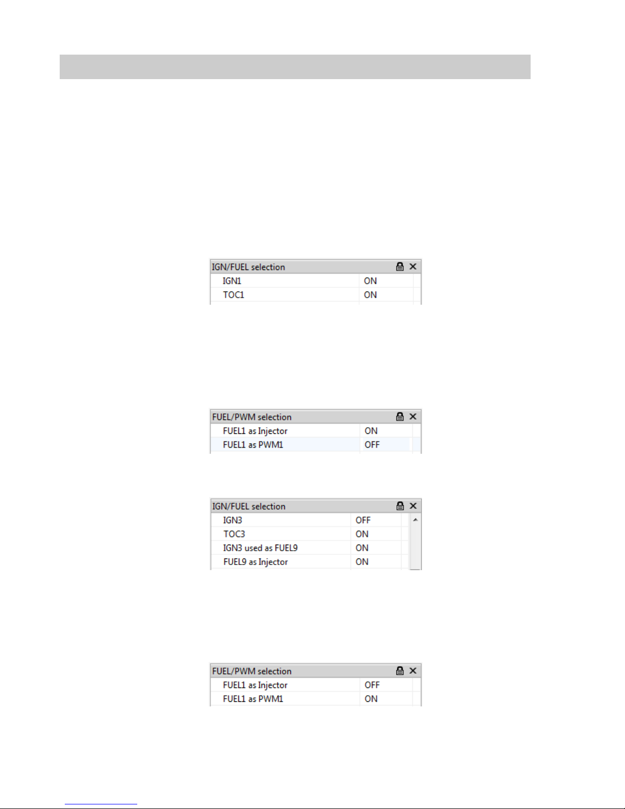
4.3 PWM Devices
PWM devices (such as idle motors, boost solenoids etc) may be controlled by any of the FUEL pins.
To set a FUEL pin as a PWM driver it must have the FUELx as PWMx ON and FUELx as injector
OFF.
Controls are then applied to these activated PWM outputs using the Setup | Output Pin Allocation
| PWM Outputs options group.
4 Inputs and Outputs
OMEM710 Hardware Manual 2v11
11
The PWM outputs will usually require inverting.
4.4 Switch Outputs
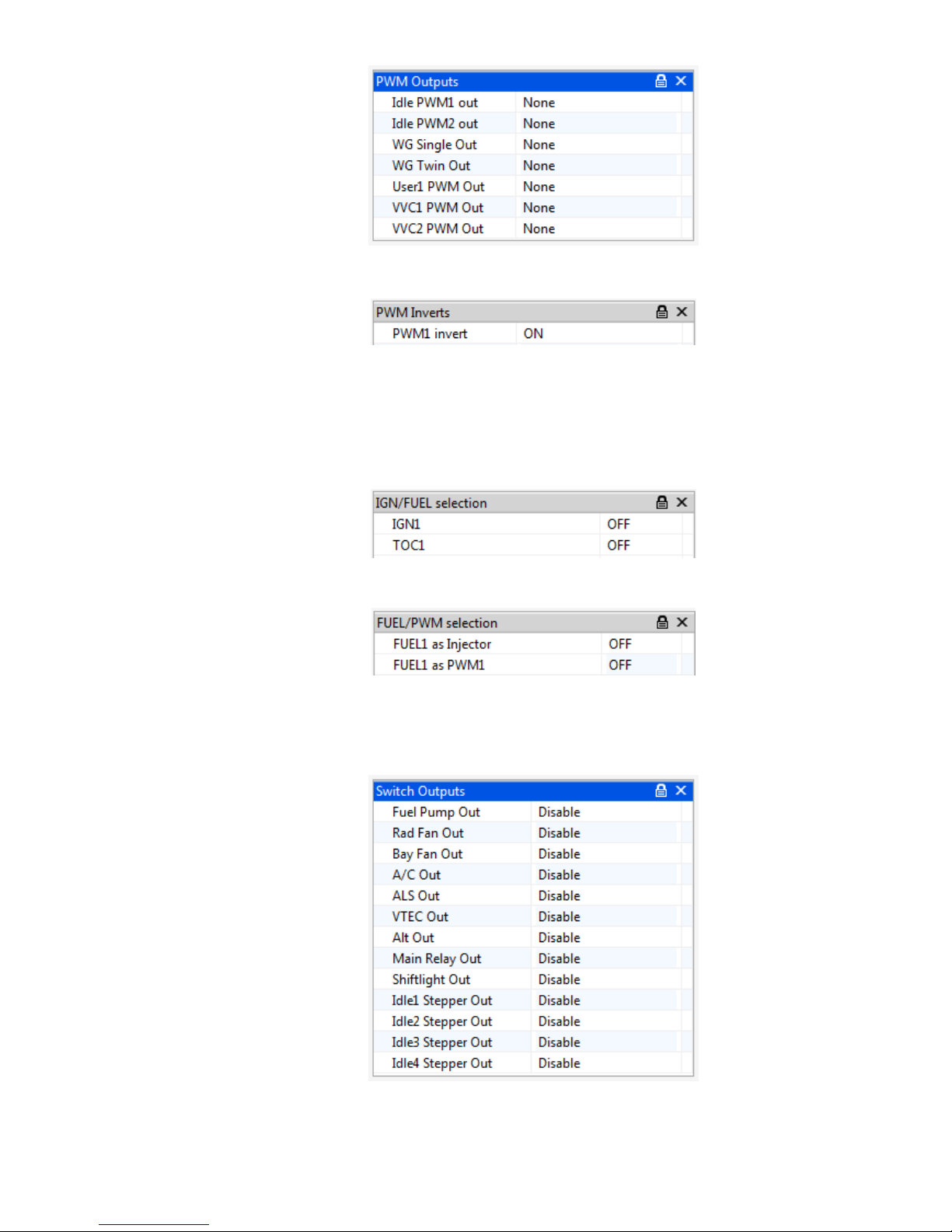
Switch outputs may be controlled by IGN pins, FUEL pins, or HIGHSIDE pins.
To set an IGN pin as a switch output it must have both the IGNx and TOCx OFF.
To set a FUEL pin as a switch output it must have both the FUELx and PWMx OFF.
The HIGHSIDE pins are switch pins only so do not need the hardware switching to this output type.
Controls are then applied to these switch outputs using the Switch Outputs drop-down options
group.
If the output needs to work in reverse (ie the output going OFF when the software function goes ON)
then use the inverted option version.
OMEM710 Hardware Manual 2v11
12
There are also options of N.U., tacho and tele. Do not use these unless instructed to do so by
Omex.
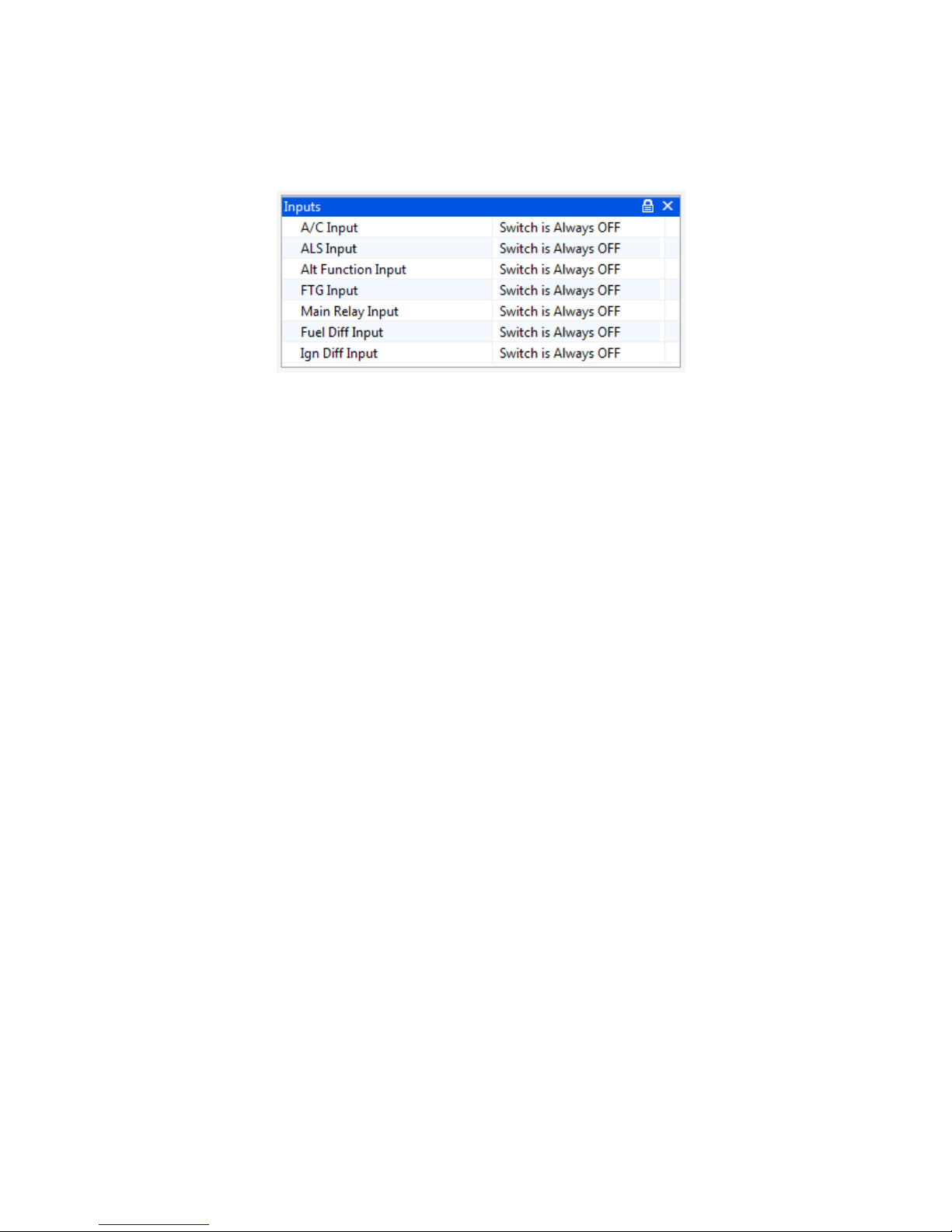
4.5 Switch inputs
Switch input pins are selected using the drop-down options. A switch input function can have any of
the input pins on the list assigned to it so long as they are not being used already by sensors. (eg. If
an oxygen sensor is being used on pin OX1, a switch clearly cannot be assigned to this pin). For a
function to be active always without a physical switch to turn it on (sometimes this is the case with
the Alt Function) select Switch is Always ON.
OMEM710 Hardware Manual 2v11
13
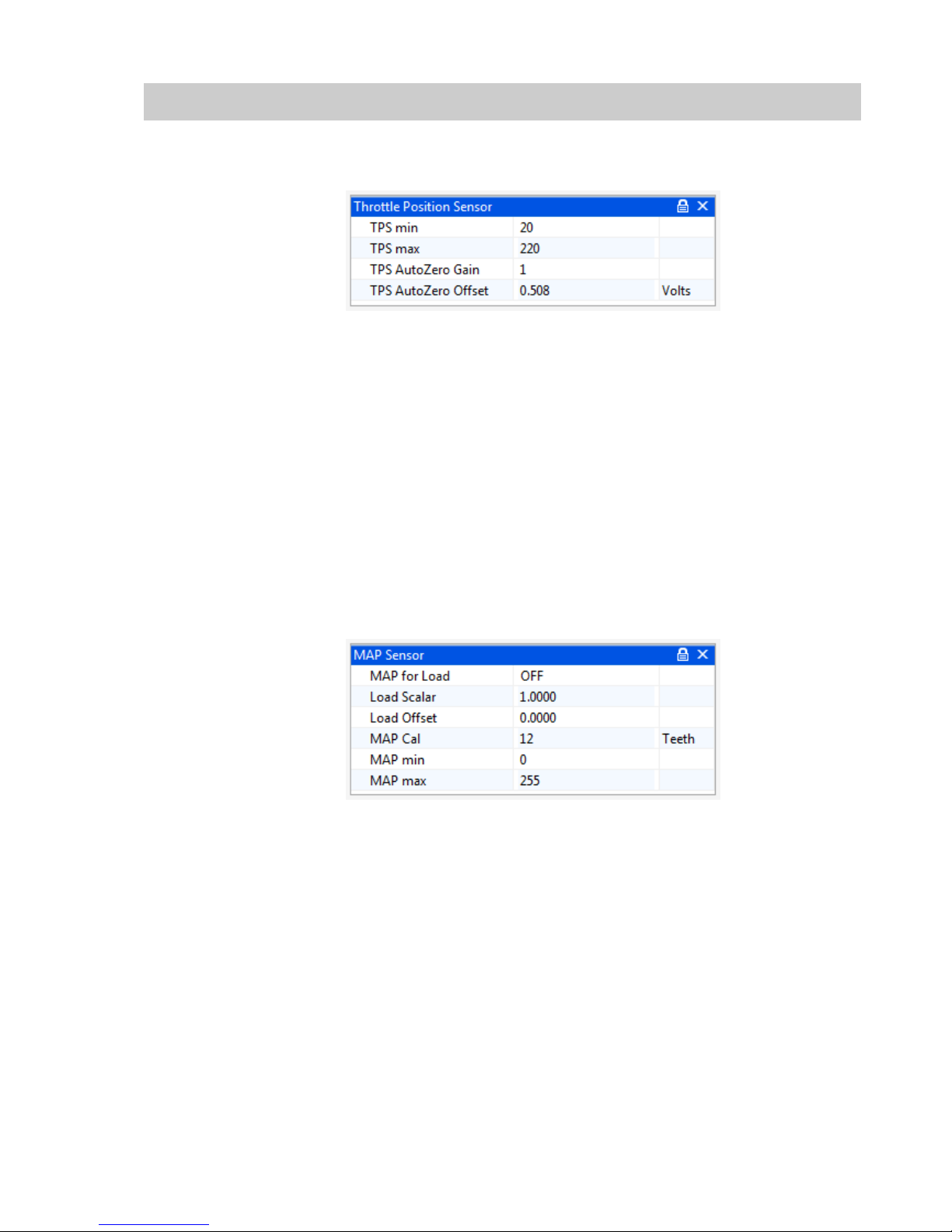
5.1 Throttle Position Sensor
The parameter TPS raw gives the raw number output of the sensor which is scaled by options TPS
min and TPS max to give a throttle that works between 0 and 100%. To calibrate;
A live reading is shown for TPS raw. TPS raw will be between 0 and 255. The throttle position
sensor can often be rotated by the user. If so, the position should be set so that the sensor
never reaches 0 or 255 during its closed throttle to open throttle movement. It is preferable to
have the sensor set so that the values do not go close to either extreme. Typically a value of
approximately 20 at the idle position will give an acceptable value at WOT (wide open throttle).
The number for TPS raw at WOT needs to have 1 added to it, then be inputted to the options
box as TPS max (i.e. if TPS Raw is 220, then input 221). The number for TPS raw at the idle
position needs inputting to the options box as TPS min.
The Autozero options allow the ECU to automatically re-learn the idle position of the throttle sensor
every time the ECU is turned on. 0 disables this feature.
5.2 MAP Sensor
If you are using MAP for engine load sensing then set MAP for Load ON.
MAP min and MAP max should be 0 and 255. Do not change these unless instructed to by Omex.
MAP Cal is the the time over which the ECU averages the MAP sensor input. Measured in internal
units. Typically 12.
As standard, the fuel map and ignition map will show load values of 0-100KPa. This is not KPa, this
is simply 0-100% of the range of the sensor. It is possible to tell the ECU what range the sensor has
so that you can read the true KPa value on the maps.
Load Scalar
The multiple of 1 that describes the theoretical 0-5V full scale of the
sensor.
Load offset
Most MAP sensors do not have 0V at 0KPa, they have a slight offset.
This option describes the offset.
5 Sensor Setup
OMEM710 Hardware Manual 2v11
14
Omex have the values for the sensors sold by Omex. If you want to calibrate your own sensor then
either find the voltage output information (total scale, and offset) from the manufacturer, or follow
this procedure;
Select a suitable start point for Load Scalar to suit your sensor e.g. for a nominally 2bar sensor,
enter 2
Note the current value for MAP as Load
Change the pressure at the sensor by a known amount using a vacuum pump
Ignoring the absolute value, adjust Load Scalar until the correct change in value is shown by
MAP as Load to suit that pressure change e.g. if you have reduced the pressure by 50kPa,
then adjust Load Scalar until MAP as Load shows 50kPa less than it did before the pressure
change was made
Remove the pressure change and try the above again. As this is an iterative procedure you may
need to do it several times before the correct change is shown on the ECU
Remove any pressure changes from the sensor and adjust Load offset until MAP as Load shows
the current barometric air pressure.
5.3 MAF Sensor
Contact Omex if you would like to use MAF as the load sensor.
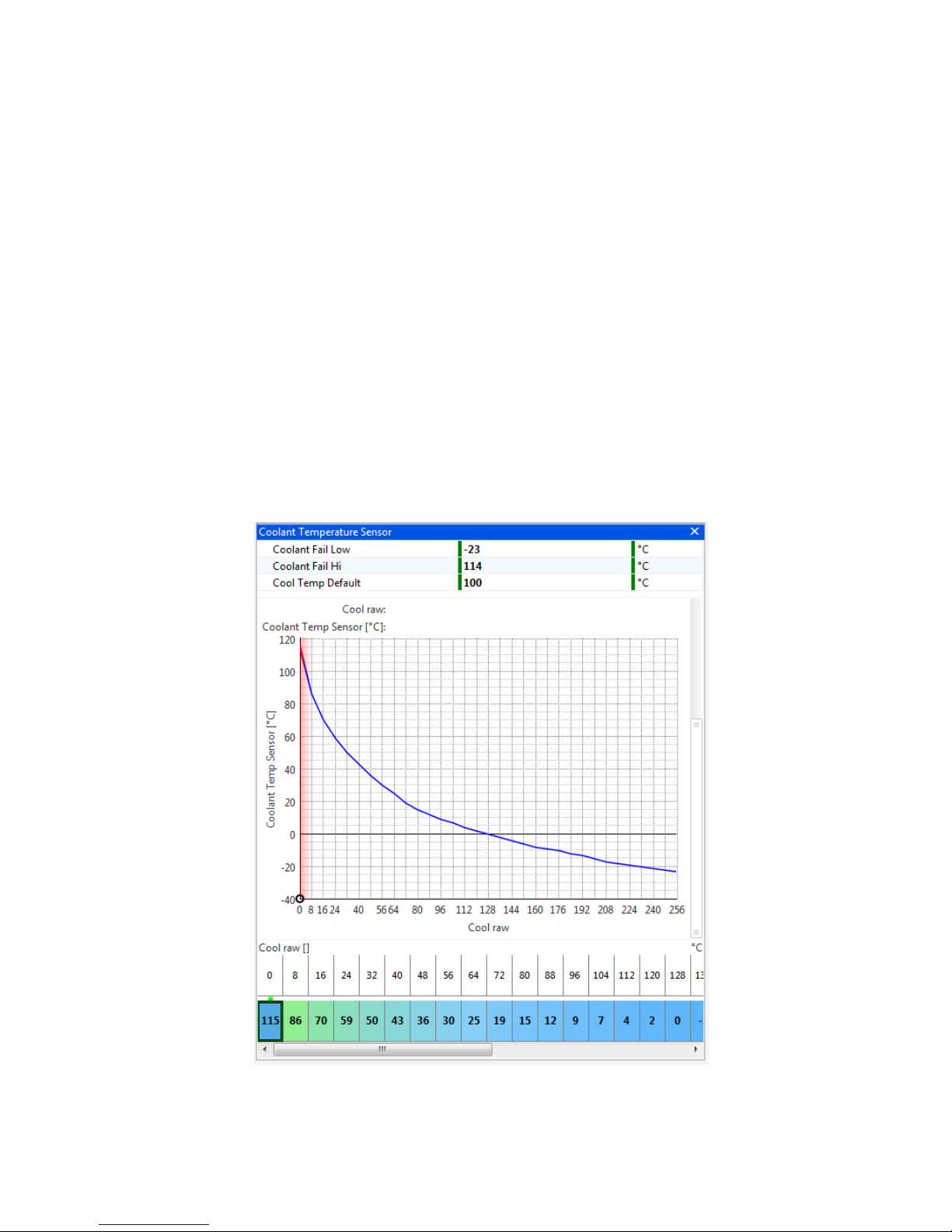
5.4 Coolant Temperature Sensor
The coolant temperature sensor used by the Omex ECU is a resistive sensor. The raw output of this
sensor is calibrated in the ECU to give the information in a more usable form, oC. Sensors are
calibrated in the Coolant Temp Sensor table. The values for many sensors are known but you may
OMEM710 Hardware Manual 2v11
15
need to calibrate your sensors. It is essential that these sensors are calibrated correctly as many
functions are temperature based.
To calibrate a sensor;
Place the sensor and a thermometer in a kettle or pan of water
The ECU will highlight the current raw input value from the sensor along the upper line of the
table. Below this input value, enter the current thermometer reading in degrees centigrade.
Heat the water. As the temperature increases, repeat the temperature readings.
When the water is fully heated, repeat the process as the water cools
Using the graph view, smooth the curve to remove any mistakes, and extrapolate to
unobtainable temperatures.
Coolant Fail Low and Hi are the failure points of the sensor and should be set to just within the
reading limits of the sensor.
Example- If the lowest temperature in the sensor table is –25 then Coolant Fail Low should be set
1 higher at –24. If the highest temperature in the sensor table is 125 then Coolant Fail Hi should be
set 1 lower to 124. Coolant Temp Default is the temperature to which the input defaults if the
sensor goes into failure.
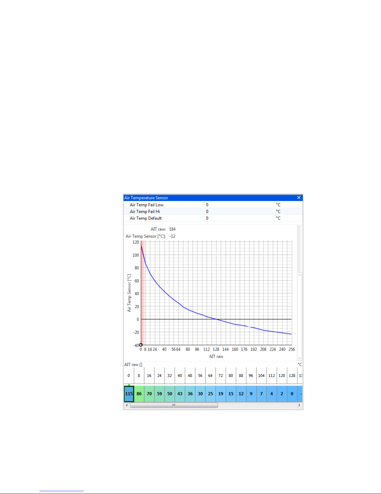
5.5 Air Temperature sensor
The air temperature sensor used by the Omex ECU is a resistive sensor. The raw output of this
sensor is calibrated in the ECU to give the information in a more usable form, oC. Sensors are
calibrated in the Air Temp Sensor table. The values for many sensors are known but you may
need to calibrate your sensors. It is essential that these sensors are calibrated correctly as many
functions are temperature based.
OMEM710 Hardware Manual 2v11
16
To calibrate your sensor, see the calibration of the coolant temperature sensor.
Air Temp Fail Low and Hi are the failure points of the sensor and should be set to just within the
reading limits of the sensor.
Example- If the lowest temperature in the sensor table is –25 then Air Temp Fail Low should be set
1 higher at –24. If the highest temperature in the sensor table is 125 then Air Temp Fail Hi should
be set 1 lower to 124. Air Temp Default is the temperature to which the input defaults if the sensor
goes into failure.
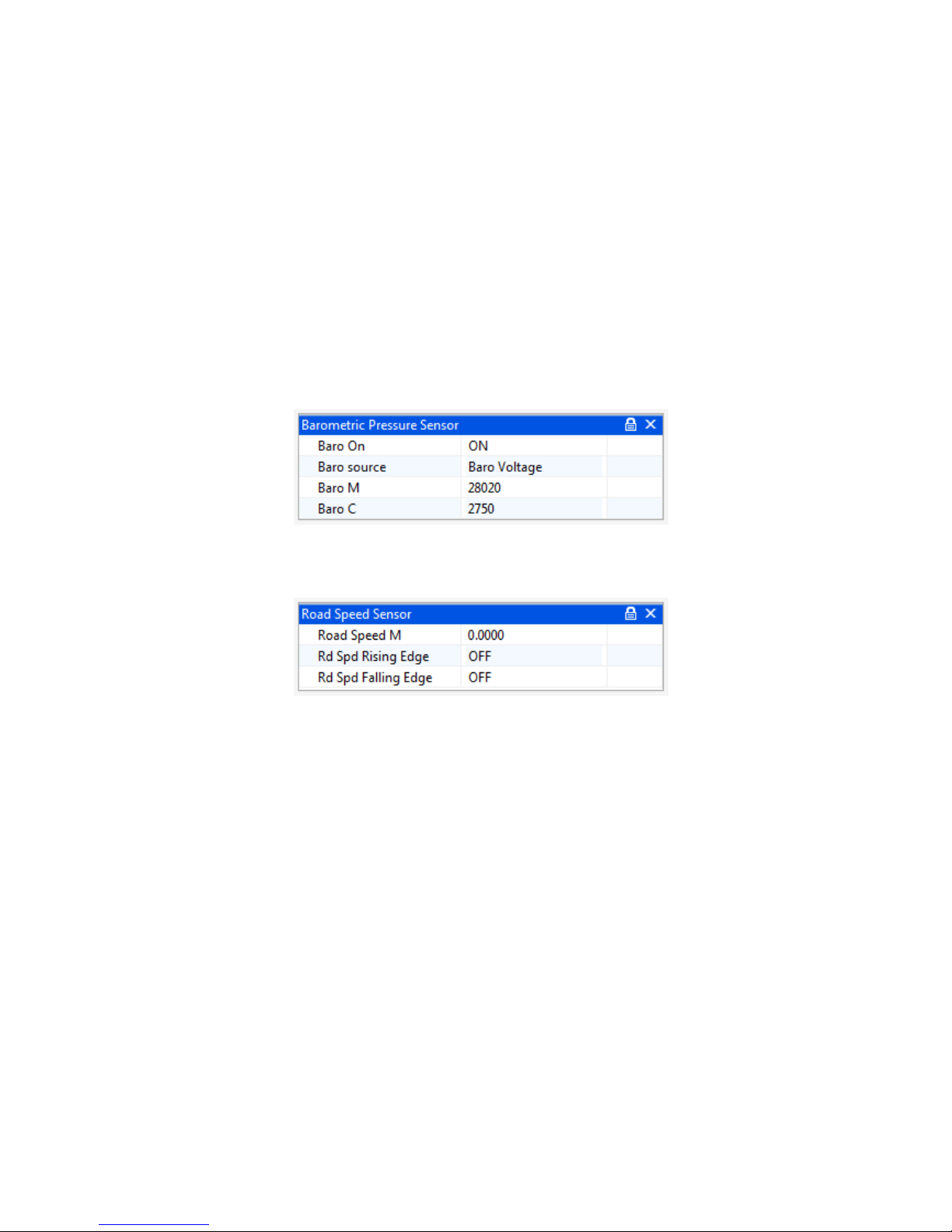
5.6 Barometric Pressure
As the air pressure changes, so does the amount of oxygen per volume of air. Changes in most
countries are relatively little, but if driving in large mountain ranges, these changes can be
significant. The 710 ECU has an in-built 1bar MAP sensor which may be used for barometric
correction. As the 710 has an inbuilt sensor, no calibration is required, the function is simply enabled
or disabled. Baro must NOT be checked if using the internal sensor for load. There is a Baro Source
option to allow the use of external baro sensors where required.
5.7 Road Speed Sensor
The road speed sensor is only required if you wish to use gear dependent shift light speeds. The
input should be a pre-differential driven wheel input e.g. propshaft rpm.
The road speed sensor can only be calibrated once the engine is running.
The option Road Speed M is a scalar and should be adjusted until the parameter Road Speed
reads the current road speed.
Rd Spd Falling Edge and Rd Spd Rising Edge specify the edge of the input waveform from the
sensor to use as the significant edge. Typically Rd Spd Falling Edge.
Road speed can be displayed as either mph or kph. To adjust the units used go to Configure |
Units/Scaling | Road Speed Units.
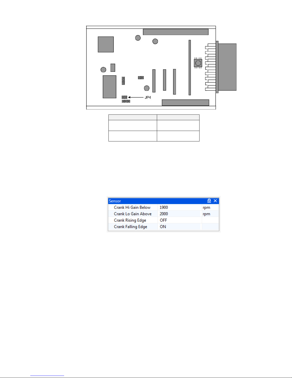
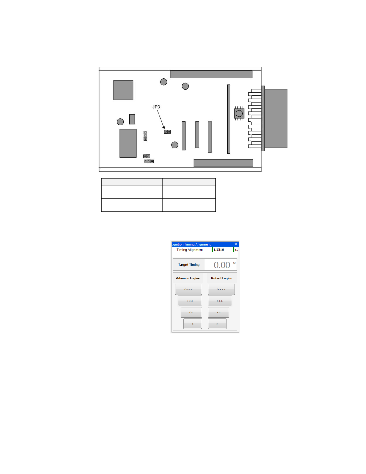
Jumper
To allow for different types of sensor, physical jumpers need to be set. The following diagram shows
an aerial view of the ECU board with the main wiring connector on the right-hand side.
OMEM710 Hardware Manual 2v11
17
Sensor Type
Jumper Position
Typical MVR
OFF
Hall Effect ON
5.8 Crank Sensor
The crank sensor input can be from either a Magnetic Variable Reluctance (MVR) sensor or a Hall
Effect sensor. The two types of sensor require different software and hardware jumper settings.
MVR
The crank sensor high and low gain settings allow a user definable change point for high sensitivity
to allow for low magnetic crank sensor outputs at low engine speeds. Typically the values are just
above idle speed.
Magnetic sensors can use either the rising or falling edge of the generated waveform. If the edge is
incorrect then the engine will misfire at some point in the engine speed range. There is also the
possibility that if the edge is incorrect on a magnetic sensor of the ignition timing on the engine
deviating from the ignition timing calculated by the ECU as the engine speed changes. To find the
correct edge either see which edge does / does not produce ignition timing changes, or using an
oscilloscope to look at the waveform. If the signal falls through the missing tooth section use Crank
Rising Edge, and if it rises through the missing tooth section use Crank Falling Edge.
OMEM710 Hardware Manual 2v11
18
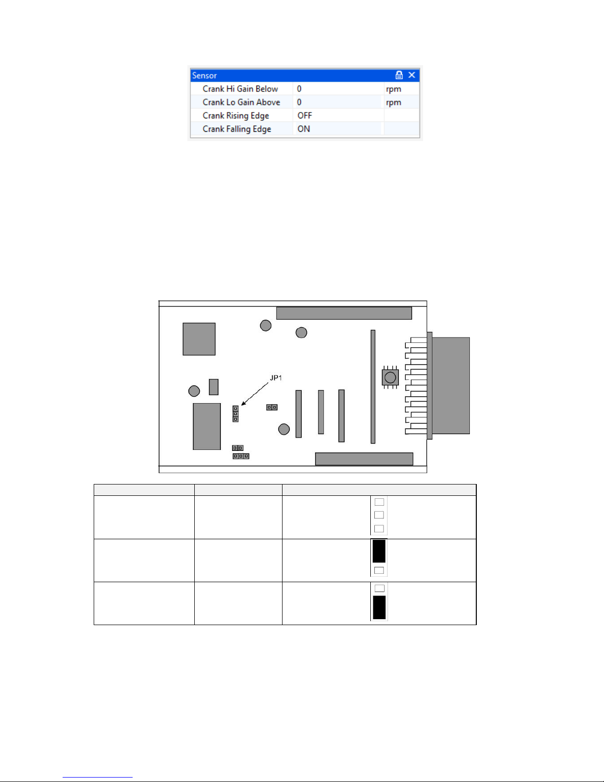
Hall Effect
Hall effect sensors require values of 0 for the high and low gain settings as their output is the same
amplitude regardless of engine speed.
Hall Effect sensors can use either the rising or falling edge, though typically the falling edge would
be used.
Jumpers
To allow for different input ranges of the crank sensors, physical jumpers need to be set. The
following diagram shows an aerial view of the ECU board with the main wiring connector on the
right-hand side.
Sensor Type
Jumper Position
Typical MVR
none
High Output MVR
1 2
Hall Effect
2 3
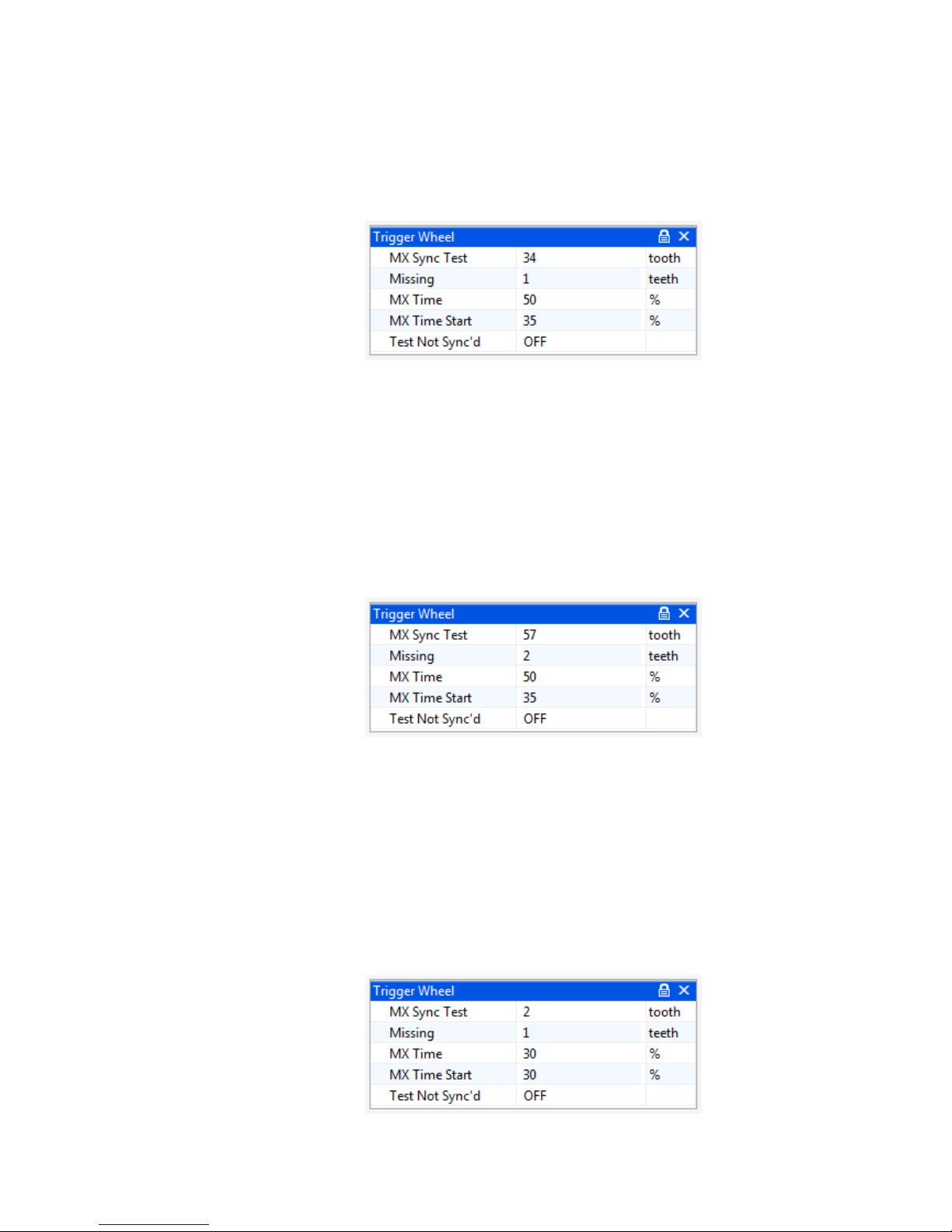
5.9 Trigger Wheel
The pattern of teeth on the crank pulley or flywheel that the crank sensor faces is known as a trigger
wheel. The pattern is evenly spaced teeth with missing or extra teeth as reference points. As
different manufacturers use different trigger patterns, the ECU is programmable to suit. The
information required in the ECU for many of the popular patterns is already known, some of which
are listed below. If you have a different pattern on your engine please contact Omex for advice.
OMEM710 Hardware Manual 2v11
19
It is very easy to make an engine run, but not run properly by incorrectly entering these
options and tables. If possible please contact Omex for a calibration aspect or email an
existing calibration to Omex to be changed to a different trigger pattern.
36-1
Tooth Control table:
0 1 2 3 4 5 6 7 8 9 10
11
12
13
14
15
16
17
18
19 5 4 4 5 4 4 5 4 4 5 4 4 5 4 4 5 4 4 5 4
20
21
22
23
24
25
26
27
28
29
30
31
32
33
34
35
36
37
38
39 4 5 4 4 5 4 4 5 4 4 5 4 4 5 4 3 3 3 3 3
40
41
42
43
44
45
46
47
48
49
50
51
52
53
54
55
56
57
58
59 3 3 3 3 3 3 3 3 3 3 3 3 3 3 3 3 3 3 3 3
60-2
Tooth Control table:
0 1 2 3 4 5 6 7 8 9 10
11
12
13
14
15
16
17
18
19
5 4 4 4 4 5 4 4 4 4 5 4 4 4 4 5 4 4 4 4 20
21
22
23
24
25
26
27
28
29
30
31
32
33
34
35
36
37
38
39
5 4 4 4 4 5 4 4 4 4 5 4 4 4 4 5 4 4 4 4
40
41
42
43
44
45
46
47
48
49
50
51
52
53
54
55
56
57
58
59
5 4 4 4 4 5 4 4 4 4 5 4 4 4 4 5 4 4 3
3
Rover K-Series (late)
OMEM710 Hardware Manual 2v11
20
Tooth Control table:
0 1 2 3 4 5 6 7 8 9 10
11
12
13
14
15
16
17
18
19 4 4 5 4 4 5 4 4 5 4 4 5 4 5 4 5 4 4 5 4
20
21
22
23
24
25
26
27
28
29
30
31
32
33
34
35
36
37
38
39 4 5 4 4 5 4 4 5 4 5 4 5 3 3 3 3 3 3 3 3
40
41
42
43
44
45
46
47
48
49
50
51
52
53
54
55
56
57
58
59 3 3 3 3 3 3 3 3 3 3 3 3 3 3 3 3 3 3 3 3
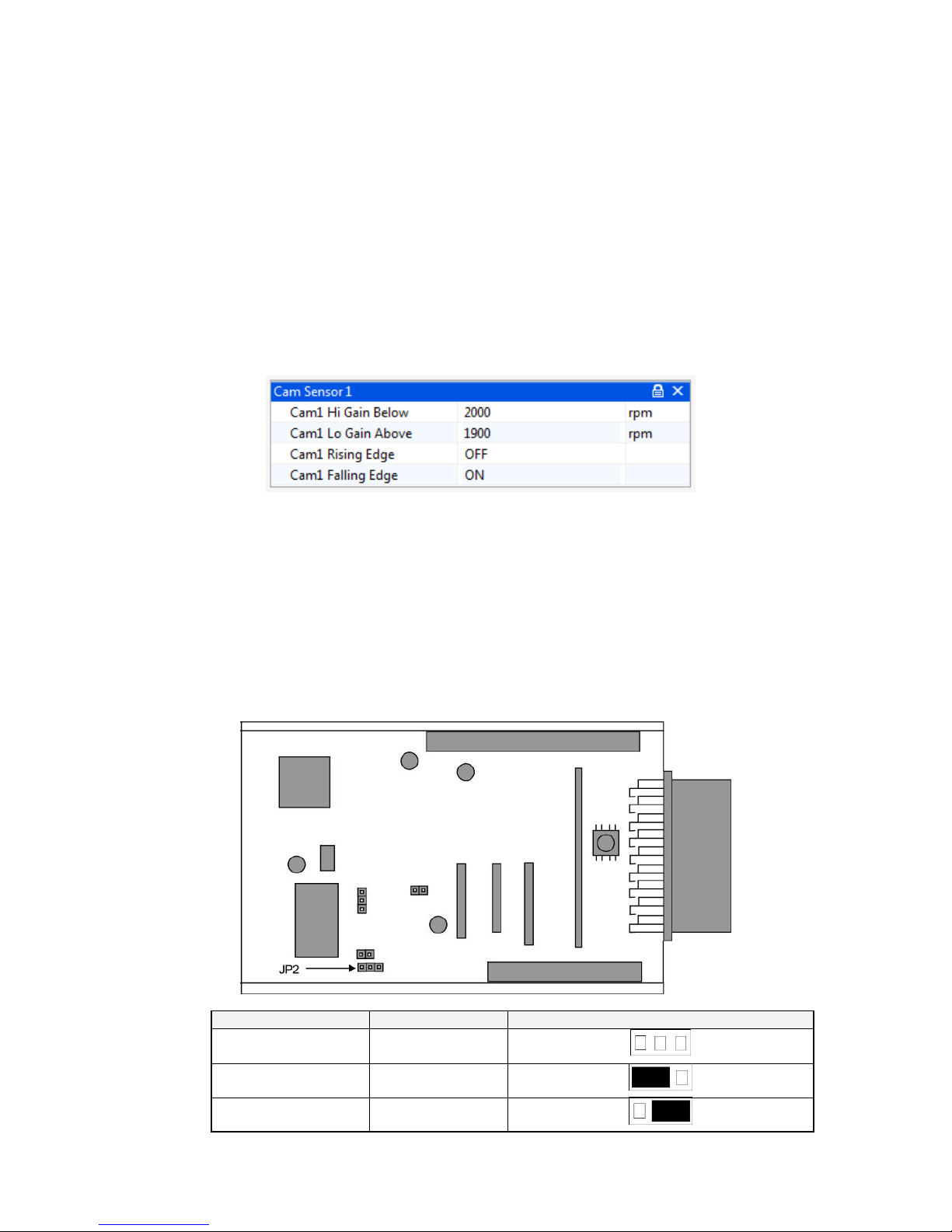
5.10 Cam1 Sensor
If an engine is to control the injectors sequentially or ignition coil-per-plug, it needs information about
what part of the engine cycle it is in (there are two crank revolutions per engine cycle for a 4 stroke
engine). The cam sensor provides this information (as there is only one cam revolution per engine
cycle for a 4 stroke engine).
Cam1 Lo Gain Above
Some VR cam sensors give too high an output at high engine speeds.
This feature allows the sensitivity of the ECU to be switched to lower
above the set engine speed to allow for this. Typically 1500rpm.
Cam1 Hi Gain Below
High channel sensitivity when below this value. Should be set below the
on value (hysteresis). Logic level sensors (hall effect) set to 0
Cam1 Rising Edge
rising edge of the crank signal is used as the significant edge if ON.
Typically OFF
Cam1 Falling Edge
falling edge of the crank signal is used as the significant edge if ON.
Typically ON
The cam input can be from either a MVR or Hall sensor. Jumpers on the board must be set to allow
for these two sensor types.
Sensor Type
Jumper Position
Typical MVR
none
High Output MVR
1 2
Hall Effect 2 3
OMEM710 Hardware Manual 2v11
21
5.11 Cam2 Sensor
The Cam2 sensor is used for some engines, typically twin VVC engines.
Sensor Type
Jumper Position
Typical MVR
OFF
Hall Effect ON
5.12 Ignition Timing Alignment
The ECU recognises the engine position by a missing or extra tooth on a pattern of evenly spaced
teeth. Different manufacturers have this reference in a different place on the trigger wheel so the
ECU needs to have adjustment for this. The numbers are known for most manufacturers and will be
set in the start-up calibration but if they are unknown or if you are using an Omex external 36-1
wheel, you will need to find this value yourself. To find this value you will need a strobe light and an
accurate TDC mark on the engine.
Hold the engine at 2000-3000 rpm (ie out of the idle condition where the ignition timing is stable)
Check the engine speed shown on the strobe light. Most strobe lights will see the wasted spark
on DIS systems and so will show double engine speed and so also double ignition timing. If this
is the case then halve all ignition timing figures shown on the strobe light.
Check the ignition timing with a strobe light and compare this number to the number in Target
Timing.
If the engine is retarded compared to Target Timing (the strobe light shows a lower value) then
advance the engine. If the engine is advanced compared to Target Timing (the strobe light

OMEM710 Hardware Manual 2v11
22
shows a higher value) then retard the engine. The larger buttons make larger changes, the
smaller buttons make smaller changes. The Target Timing on the PC will not change, but the
timing mark on the engine will move, so each adjustment will require the strobe light resetting.
Repeat these changes until the strobe light timing figure agrees with the Target Timing figure.
If you cannot get the engine to start and believe this is because the ignition timing is incorrect then
you can perform the above tests whilst cranking the engine. Timing lights will not work correctly
during normal cranking as the engine speed varies so much due to the compression of each
cylinder. Therefore the spark plugs should be removed (to remove compression), put back into the
HT leads, and placed onto an earthed part of the engine, then the process documented above can
be followed but at cranking speeds. When this is done and you get the engine started, it should be
repeated at normal running speeds.
 Loading...