

OMEX 200, OMEM200 Installation Manual
ENGINE MANAGEMENT SYSTEMS
OMEM200 Installation Manual 2v10
200 Series ECU
Installation Manual
OMEM200
www.omextechnology.com


OMEM200 Installation Manual 2v10
Contents
1 Introducing Omex Engine Management.......................................................................................................4
2 Standard Functions........................................................................................................................................5
2.1 Crank Position Sensor (CPS)..................................................................................................................5
2.2 Throttle Position Sensor (TPS)................................................................................................................8
2.3 Coolant Temperature Sensor (CTS).......................................................................................................9
2.4 Air Temperature Sensor (ATS)..............................................................................................................10
2.5 Manifold Absolute Pressure (MAP) Sensor...........................................................................................11
2.6 Ignition Coil(s).......................................................................................................................................12
2.7 Shift Light..............................................................................................................................................15
2.8 Tachometer...........................................................................................................................................16
2.9 Fuel Pump.............................................................................................................................................17
2.10 Radiator Fan........................................................................................................................................18
2.11 VTEC Cam Control..............................................................................................................................19
2.12 Full Throttle Gear Shift........................................................................................................................20
2.13 Alt Mode..............................................................................................................................................20
3 Wiring............................................................................................................................................................21
3.1 Semi Assembled Loom Construction....................................................................................................21
3.2 Ready Built Harness..............................................................................................................................21
3.3 ECU Connector.....................................................................................................................................22
3.4 Typical Complete Wiring.......................................................................................................................24
3

1 Introducing Omex Engine Management
Thank you for choosing Omex Engine Management. This manual is written to help the user through the
specifics of installing the OMEM200 ECU. It is essential that the user reads the whole of the manual
before attempting to install the system. Incorrect use of the Omex system could potentially lead to
damage to the engine and personal injury. If you have any doubts about fitting these parts then please
contact Omex for help.
Omex may not be held responsible for damage caused through following these instructions, technical,
or editorial errors or omissions. If you have any doubts about fitting these parts or using the software
then please contact Omex for help.
OMEM200 Installation Manual 2v10
4

2 Standard Functions
2.1 Crank Position Sensor (CPS)
Trigger Wheel
The ECU needs to know engine speed and position in order to supply the correct fuelling and ignition
timing. This is often achieved using the standard sensors, but can involve putting new sensors on the
engine. Engine speed is measured using a pattern of teeth on a crank wheel or flywheel (known as a
trigger wheel). The 200 ECU supports the following patterns;
Ford 36-1 Rover 18-1, 18-1 (distributor ignition only)
Bosch 60-2 Toyota 36-2
Rover K (late) Honda 12+1
If you have any doubt as to whether the trigger pattern on your engine is supported by the 200 ECU,
then remove the sensor, count the pattern of teeth, and contact Omex.
Many older engines do not have a trigger wheel. In this case an external wheel must be fitted. 36-1 is
our preferred pattern. There is a minimum diameter for these wheels dependent on the sensor used,
the trigger pattern, and the engine operating speeds. Typically the larger the trigger wheel diameter the
better. The wheel needs to be mounted on the front pulley. It may also be possible to machine this
pattern into the front pulley wheel, remembering that the pattern must be in a ferrous material for the
sensor to work and if the crank pulley has a damper inbuilt you must mount the trigger wheel onto the
crank side of this damper. Omex can supply general purpose trigger wheels in diameters of 100mm and
140mm.
OMEM200 Installation Manual 2v10
If installing a trigger wheel of missing tooth type,
Ÿ Accurately mark TDC.
Ÿ Mount your crank position sensor (CPS) anywhere around the perimeter of the trigger wheel
pointing towards the centre of the wheel such that the sensor can touch the pulley (it will be
spaced out so that it does not touch later). The mount should be strong enough that you can
lean on it and it not move.
Ÿ Mount the trigger wheel so that the missing tooth is approximately 90 degrees after the crank
sensor. (the exact angle can be adjusted in software but for first start of the engine it helps if
you are within 10 degrees of this position). If the crank pulley has a damper inbuilt you must
mount the trigger wheel onto the crank side of this damper.
Ÿ Run the crank pulley / trigger wheel assembly in a lathe to ensure that the trigger wheel is
exactly central on the pulley.
Ÿ Refit the pulley / trigger wheel assembly and adjust the sensor-to-wheel gap to 0.3mm-
0.5mm by spacing out the sensor with shims.
Ÿ Rotate the pulley and ensure that the gap does not alter by more than 0.2mm.
Clockwise rotating engine
at cylinder 1 TDC
Anti-clockwise rotating engine
at cylinder 1 TDC
90°90°
5
OMEM200 Installation Manual 2v10
If machining a trigger pattern into the front pulley then it is usually easiest to machine all of the teeth in,
mount the front pulley, and then remove the tooth pointing at the sensor at 90o BTDC.
Sensor
There are two types of crank position sensor; MVR and Hall Effect. The Hall Effect type require ignition
switched power to make them work.
2 wire sensors must be MVR. Usually terminal 1 is the signal and terminal 2 the timing ground
3 wire sensors can be either MVR or Hall Effect. If MVR, then usually terminal 1 is the signal, terminal
2 the timing ground and terminal 3 has no connection. If Hall Effect, there is no way of measuring
externally to find which pin has which function; you must find out from the manufacturer.
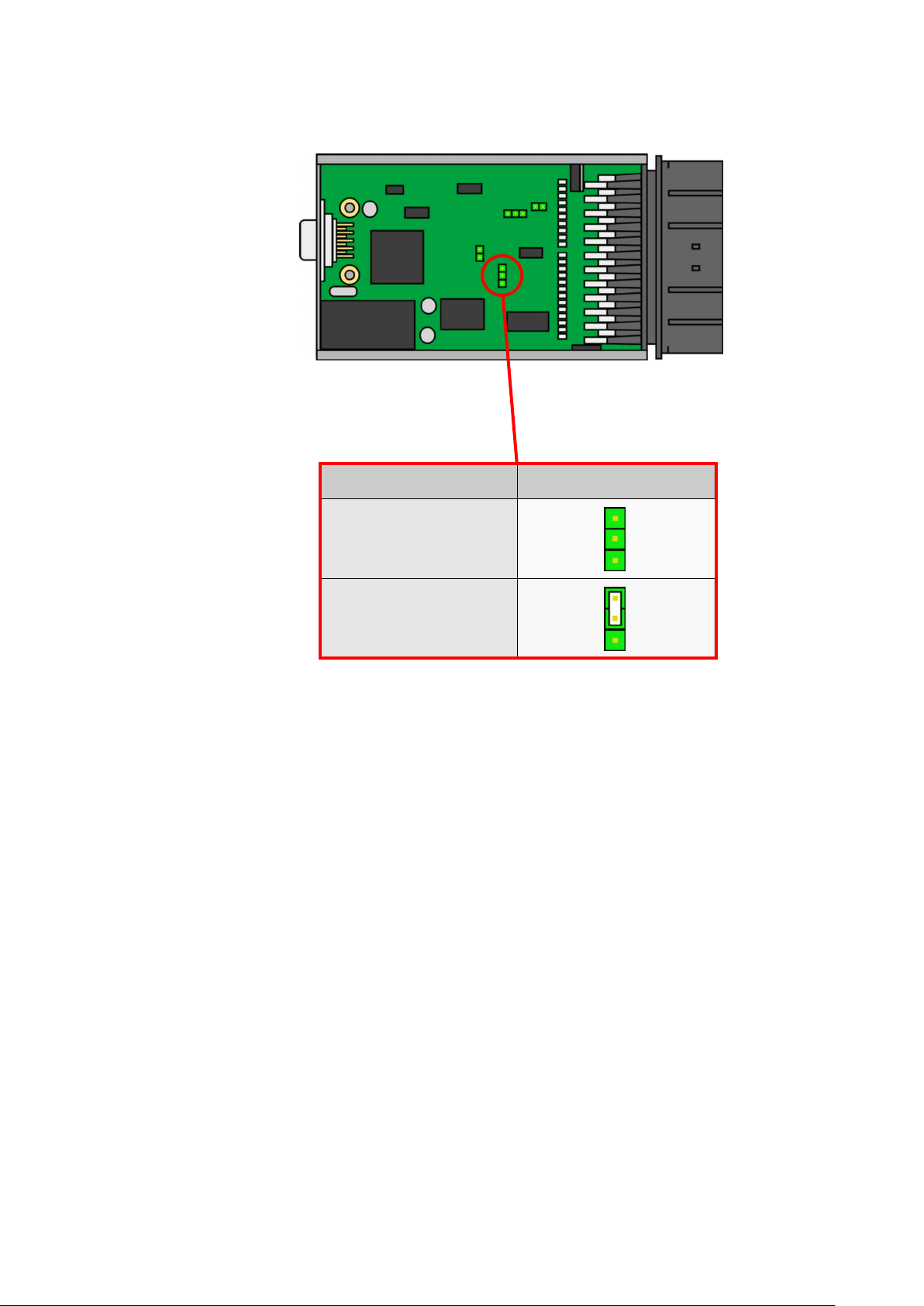
If the sensor is Hall Effect, a jumper (supplied with the ECU) must be put onto header pins on the ECU
board.
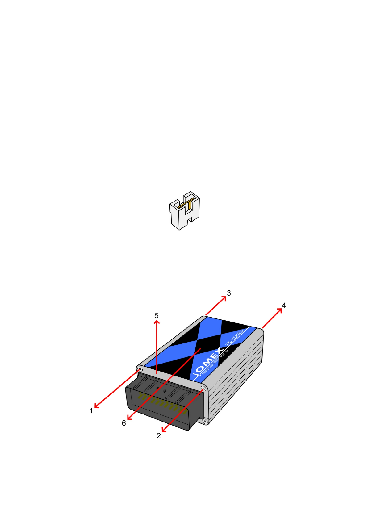
To fit this part you will need to part-disassemble the ECU to gain access to the board. As shown in the
diagram;
· remove screws (1, 2, 3 and 4)
· slide up the end plate (5)
· slide off the lid plate (6)
6
OMEM200 Installation Manual 2v10
JP1
Sensor Type Jumper Position
MVR
Hall Effect
no
jumper
7

2.2 Throttle Position Sensor (TPS)
OMEM200 Installation Manual 2v10
The addition of a throttle position sensor allows varying ignition timing with changes in engine load;
similar to a ‘vacuum advance’. This sensor must be placed on the end of the throttle spindle.
Pin-outs
If you have purchased a throttle position sensor from Omex, then the pin-outs for your sensor can be
found on the information sheet with the sensor. If you are using an unknown sensor then you will need
to test the potentiometer to find this information.
Allocate the sensor terminals with numbers 1,2,3. With the sensor disconnected from any wiring use a
multimeterontheresistancesetting(kΩ)tomeasuretheresistancebetweeneachoftheterminalswith
the throttle in an approximate closed position and then with the throttle in an approximate open position
(the absolute position is not important).
Between two of the terminals the resistance will not change as the throttle is opened. This tells us that
the remaining terminal is the signal (Omex orange cable). From the remaining two terminals, one of
them will have a resistance to the signal that is lower when throttle open than when throttle closed, this
is the 5V reference voltage terminal (Omex pink cable). The last terminal must therefore be the sensor
0V (Omex grey cable).
Example;
Closed
1 2 3
When the throttle position is moved from closed to open, the resistance does not change between 1
and 3. Therefore, 2 must be the signal (Omex orange). 3 has the lower resistance to the signal with the
throttle open and so must be the 5V (Omex pink), leaving 1 to be the sensor 0V (Omex grey).
5200
4300400
Open
1 2 3
5200
4004300
8
 Loading...