

Page 1
Come risolvere i problemi - Trouble shooting
®®
Problema
Perdita d’aria dal
battente
Perdita d’aria dal
coperchio
Perdita d’aria dal
cilindro
Mancato
funzionamento
Inceppamento
Problem
Trigger leaks air
Exhaust cap leaks air
Cylinder leaks air
Failure cycling
Jamming
Possibile Causa
O-ring sulla valvola (35P016) o il tubo
(35P017N) sono rovinati.
1-
O-ring sulla valvola (35P016) o il tubo
(35P017N) sono rovinati.
2- O-ring 35P042N è rovinato.
O-ring del pistone rovinato.
1- Vite 35P054 allentata.
2- 35P009, 35P014 rotti per usura.
1- Dimensioni delle graffe sbagliate.
2- Lubrificazione insufficiente.
3- Vite allentata.
Possible Cause
O-rings on valve (35P016) or tube (35P017N)
cut or broken.
1- O-rings on valve (35P016) or tube
(35P017N) cut or brokem.
2- O-rings 35P042N cut or broken.
O-rings of piston rod cut or broken.
1- Screw 35P054 loose.
2- 35P009, 35P014 worn aut.
1- Wrong sizes of staples.
2- Insufficient lubrication.
3- Jaw screw loose.
Soluzione
Sostituire le parti rovinate
Sostituire le parti rovinate
Sostituire O-ring
1- Controllare e stringere la vite 35P054.
2- Controllare e cambiare i pezzi 35P009,
35P014.
1 - Usare graffe corrette.
2- Lubrificare in modo corretto.
3- Controllare la vite 35P054.
Correction
Replace the O-rings
Replace the O-rings
Replace the O-ring
1- Check and tighten screw 35P054.
2- Check and replace the parts 35P009,
35P014.
1 - Use staples in correct size.
2- Lubricate properly.
3- Check and tighten screw 35P054.
Manuale d’uso, manutezione e parti di ricambio Parte 2
Use, maintenance and spare parts manual Part 2
197B18RT_3818Roll 100510 IV
Dati tecnici
Technical data
Misure impiegabili mm
Usable lenghts mm
Capacità caricatore n° punti
Magazine capacity No. of fasteners
Pressione d’esercizio
Working pressure
Consumo aria litri/colpo
Air consumption litres/shot
Peso kg
Weight kg
Dimensioni (AxBxH) mm
Dimensions mm
15÷18
1000
5÷7 bar
70÷100 psi
1,32
2,35
237x115x222
34.18 Roll
cod. 197B18RT
Tipo di punto
Type of fastener
ROLL 34
0,90x1,90
18
15
Gauge: 16,5
3/4”
5/8”
Note - Notes
ISO 11201
Pressione sonora in pos. operatore
Sound pressure at the workstation
ISO 3744
Potenza sonora emessa
Emitted sound power
ISO 5349-86
Valore medio ponderato di vibrazione
sull’impugnatura max.33 colpi
Weighted mean value of vibration
on the grip max.33 shots
omers.p.a.
Via Foresto 42 - 31058 SUSEGANA TV ITALY Tel.0438455520 Fax 0438455530 E-mail: [email protected] http://www.omer.it
84,3 dB(A)
93,7 dB(A)
<2,5 m/s
61
2-1/4”
18
15
2
67
2-1/2”
3/4”
5/8”
Page 2
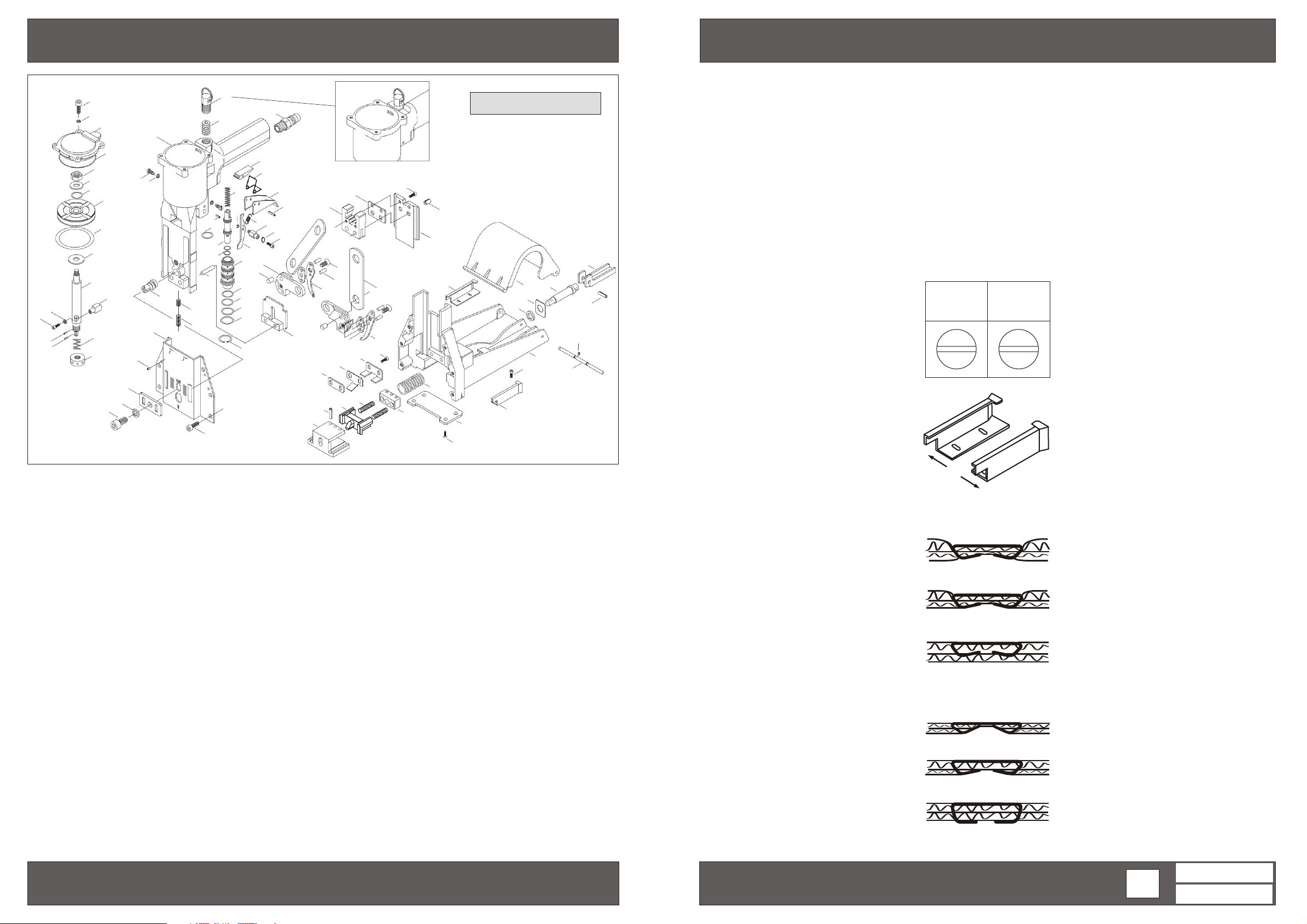
Parti di ricambio - Spare parts
Istruzioni d’uso - How using the tool
48
55
1
49
50
51
52
2
53
54
3
4
55
56
91
57
Ref. No. Part No. Description
1 32P501 Cap
2
3
4 35P004 Block
5 35P005 Spring
6 35P006 Collar
7 35P007N Body
8
9 35P009 Block
10 35P010 Spring
11 Trigger
12
13 Rod
14 35P014 Trigger control
15 35P015 Spring
16 35P016 Valve
17 Tube
18 35P018 Adjusting rod
19
20 Front plate
21 35P021 Right jaw
22 35P022 Left jaw
23 Jaw seat
24 Plate
25 Block
26 19B026 Driver
27 19B027 Driver guide unit
29
30
5
6
74
73
35P002N Piston
35P003N Piston rod
35P008 Air plug
35P011
35P012 Spring
35P013
35P017N
35P019 Adjusting plate
32P520
35P023
35P024
35P025
19B029 Anvil
19B030 Pusher
7
59
55
18
20
75
19
93
58
86
64
65
16
52
71
90
72
76
8
9
10
15
17
67
68
69
70
88
Ref. No. Part No. Description
31 19R031 Spring
32 19R032 Anvil cap
33 19R Spring
34 19R
35 19R
36 19R
37 19B037 Right coil guide
38 19B038 Left
39 19R
40 19R
41 19S041 Washer
42 19R
43 19R
44 19R044 Cover
45
46
47 Washer
48
49
50
51
52
53
54
55 Spring washer
56
57
58
59
11
61
12
13
62
63
14
23
79
27
033
034 Plate
035 Top guide
036 Left spring
039 Magazine
040 Shaft
042 Shaft
043 Lever
35P092 Plate
35P040 Washer
35P042NA
35P040N Screw
35P042N O-ring
35P043 Nut
35P044 Washer
35P045 O-ring
35P046N O-ring
35P047 Washer
35P041
35P048 Screw
35P049 Spring pin
35P050 Screw
35P051 Screw
46
25
77
78
22
45
35
36
47
31
30
82
29
coil guide
48
81
26
24
21
76
32
37
33
84
Ref. No. Part No. Description
61 35P052 Spring pin
62 35P053 Teeth Washer
63 35P054 Screw
64
65
67
68
69 35P060 O-ring
70 35P061 O-ring
71 35P062 Rod
72 35P063 Screw
73 35P064 Screw
74 35P065 Spring washer
75 35P066 Spring pin
76 32P570 Screw
77 35P069 Screw
78 35P070 Pin
79 35P071 Pin
81 35P072 Spring pin
82 19B081 Spring pin
84 35P082N Screw
85 19B084 Screw
86 35P081 E-ring
87 19B086 Spring pin
88 35P080N C-ring
90 35P084 Heli coil
91 35P085 Plastic pin
92 19B090 Wave washer
93 19B091 Counter balance hange
Kit O-Ring CRTORK1
92
38
34
35P066 Spring pin
35P056 O-ring
35P058 O-ring
35P059 O-ring
43
44
42
41
39
85
87
86
40
COME CARICARE LE GRAFFE
1 - Togliere l’alimentazione.
2 - Premere il coperchio (19R044) aprirlo
facendolo ruotare.
3 - Porre la bobina di graffe nell’apposita sede
nel caricatore (19R039). Alimentare con la
parte finale della bobina l’apposita guida.
Spingere fino in fermarsi nella guida
battente.
4 - Ruotare il coperchio fino alla chiusura.
REGOLAZIONE IN BASE ALLA LUNGHEZZA
DELLA GRAFFA
Togliere l’alimentazione.
1 -
2 - Allentare il grano (35P063).
3 - Girare la vite (35P018) posizionandola con
la “S” in alto graffe corte o con la “L” in alto
per graffe lunghe.
4 - Stringere di nuovo il grano
(35P063).
5 - Regolare la guida destra e sinistra (19B037-
19B038) nella posizione più stretta quando
si utilizzano graffe di lunghezza 15 mm o 16
mm (posizione S verso l’alto) o nella
posizione più larga quando si utilizzano
graffe di lunghezza 18 mm o 19 mm
(posizione L verso l’alto). (Vedi Fig. 1)
COME ADDATTARE
A. Profondita’
Togliere l’alimentazione.
1 -
2 - Allentare la vite (35P064).
3 - Far scorrere la piastra frontale
(32P520)
verso l’alto o il basso e posizionare la
piastra di regolazione (35P019) su una
delle tacche da 1 a 4 a seconda della
maggiore o minore profondità desiderata.
(Vedi Fig. 2)
B. Chiusura
1 - Girare il collare con un perno in
(35P006)
senso orario per una maggiore ribaditura e
in senso antiorario in caso contrario.
(Vedi Fig. 3)
Fig. 1
15 mm 18 mm
16 mm
19 mm
S
L
Fig. 2
N° 1
NO. 1
N° 2 e 3
NO. 2 & 3
N° 4
NO. 4
Fig. 3
CHIUSO
TIGHT
MEDIO
MEDIUM
APERTO
LOOSE
L
S
HOW LOADING THE STAPLES
1 - Disconnect the air pressure.
2 - Slightly squeeze cover then pull
(19R044)
to open.
3 - Place coil staples in magazine .
(19R039)
Feed front end of coil staples into right coil
guide, left coil guide and top guide.
4 - Push forward until stopping in driver guide
unit then swing cover closed.
HOW SETTING THE LENGTH OF THE STAPLE
LEGS
1 -
Disconnect the air pressure.
2 - Screw off bolt
3 - Turn the ajusting rod
(35P063).
(35P018) to put “S”
up for shorter staples and to put “L” up for
longer ones.
4 - Tighten bolt
(35P063).
5 - Adjust right and left slides (19B037-
19B038) in the narrowest position when
shooting staples of 15 mm (5/8”) or 16
mm long (adjusting rod set with “S” in the
up position) or the widest position when
shooting staples of 18 mm (3/4”) o 19 mm
long (adjusting rod set with “L” in the up
position). (See picture no. 1)
HOW TO ADJUST
A. Depth
Disconnect the air pressure.
1 -
2 - Screw off bolt
(35P064).
3 - Slide front plate (32P520) up or down and
set the top of the adjusting plate (35P019)
on position no. 1 for deepest penetration
and no. 4 for the shallow one. (See picture
no. 2)
B. Clinching
1 - Turn collar
(35P006) with a stick through
the window, clockwise for a tigh clinch and
couterclockwise for a loose clinch. (See
picture Fig. 3)
34.18 Roll
cod. 197B18RT
34.18 Roll
197B18RT_3818Roll 100510 IV
cod. 197B18RT
Indice di modifica
Upgrade number
1
 Loading...