

Page 1
omega.com
e-mail: info@omega.com
For latest product manuals:
omegamanual.info
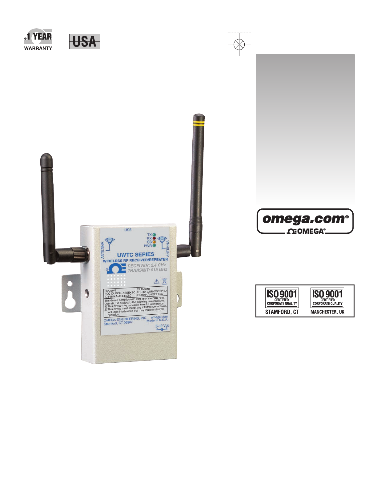
UWTC-RPT1
Long Range
Wireless
Repeater/Receiver System
For UW Series Transmitters
MADE IN
Shop online at
User’s Guide
Page 2

Servicing North America:
U.S.A.: Omega Engineering, Inc., One Omega Drive, P.O. Box 4047
ISO 9001 Certified Stamford, CT 06907-0047 USA
Toll Free: 1-800-826-6342 TEL: (203) 359-1660
FAX: (203) 359-7700 e-mail: info@omega.com
Canada: 976 Bergar
Laval (Quebec), H7L 5A1 Canada
Toll-Free: 1-800-826-6342 TEL: (514) 856-6928
FAX: (514) 856-6886 e-mail: info@omega.ca
For immediate technical or application assistance:
U.S.A. and Canada: Sales Service: 1-800-826-6342/1-800-TC-OMEGA
®
Customer Service: 1-800-622-2378/1-800-622-BEST
®
Engineering Service: 1-800-872-9436/1-800-USA-WHEN
®
Mexico/ En Español: 001 (203) 359-7803 FAX: 001 (203) 359-7807
Latin America: info@omega.com.mx e-mail: espanol@omega.com
Servicing Europe:
Benelux: Managed by the United Kingdom Office
Toll-Free: 0800 099 3344 TEL: +31 20 347 21 21
FAX: +31 20 643 46 43 e-mail: sales@omegaeng.nl
Czech Republic: Frystatska 184
733 01 Karviná, Czech Republic
Toll-Free: 0800-1-66342 TEL: +420-59-6311899
FAX: +420-59-6311114 e-mail: info@omegashop.cz
France: Managed by the United Kingdom Office
Toll-Free: 0800 466 342 TEL: +33 (0) 161 37 29 00
FAX: +33 (0) 130 57 54 27 e-mail: sales@omega.fr
Germany/Austria: Daimlerstrasse 26
D-75392 Deckenpfronn, Germany
Toll-Free: 0800 6397678 TEL: +49 (0) 7056 9398-0
FAX: +49 (0) 7056 9398-29 e-mail: info@omega.de
United Kingdom: OMEGA Engineering Ltd.
ISO 9001 Certified One Omega Drive, River Bend Technology Centre, Northbank
Irlam, Manchester M44 5BD United Kingdom
Toll-Free: 0800-488-488 TEL: +44 (0) 161 777-6611
FAX: +44 (0) 161 777-6622 e-mail: sales@omega.co.uk
OMEGAnet®Online Service Internet e-mail
omega.com info@omega.com
It is the policy of OMEGA Engineering, Inc. to comply with all worldwide safety and EMC/EMI
regulations that apply. OMEGA is constantly pursuing certification of its products to the European New
Approach Directives. OMEGA will add the CE mark to every appropriate device upon certification.
The information contained in this document is believed to be correct, but OMEGA accepts no liability for any
errors it contains, and reserves the right to alter specifications without notice.
WARNING: These products are not designed for use in, and should not be used for, human applications.
Page 3

UTWC-RPT1 - Long Range Wireless
Repeater/Receiver System For UW Series Transmitters
i
Table of Contents
Section Page
Section 1 Introduction ......................................................................................... 1-1
1.1 Precautions ................................................................................................. 1-1
1.2 Safety Warnings and IEC Symbols ........................................................ 1-1
1.3 Product Labeling ....................................................................................... 1-2
1.3.1 Receiver Front Label UWTC-REC1-915.......................................... 1-2
1.3.2 Repeater Front Label UWTC-REC1................................................. 1-2
1.4 Statement on FCC and CE Marking ....................................................... 1-4
1.4.1 FCC Marking ..................................................................................... 1-4
1.4.2 CE Marking ........................................................................................ 1-4
1.5 General Description & System Components ........................................ 1-4
1.5.1 General Description .......................................................................... 1-4
1.5.2 System Components ......................................................................... 1-4
Section 2 Hardware .............................................................................................. 2-1
2.1 Package Inspection ................................................................................... 2-1
2.2 Included Items ........................................................................................... 2-1
2.3 Accessories ................................................................................................. 2-1
Section 3 Software ................................................................................................ 3-1
3.1 Getting Started ........................................................................................... 3-1
3.2 Software Installation ................................................................................. 3-1
3.2.1 System Requirements ....................................................................... 3-1
3.2.2 Software Installation ......................................................................... 3-1
3.3 USB Driver Installation ....................................................................... 3-4
3.4 UWTC Connector/Transmitter Setup Utility Program
UWTC TC-Central Measurement and Recording Program .............. 3-6
Section 4 Receiver Setup...................................................................................... 4-1
4.1 Antenna Connection ................................................................................. 4-1
4.4.1 Configure Your Receiver (UWTC-REC1-915) ............................... 4-2
Section 5 Repeater Setup .................................................................................... 5-1
5.1 Connecting Your Receiver To Your PC ................................................... 5-1
5.1.1 Configure Your Repeater ................................................................ 5-2
Section 6 Repeater Mounting and Installation .............................................. 6-1
6.1 Mounting .................................................................................................... 6-1
6.3 Installation ................................................................................................. 6-2
6.3 Antenna Connection ................................................................................. 6-3
Section 7 System Operation ............................................................................... 7-1
7.1 Introduction ............................................................................................... 7-1
7.2 RF Communication Basics ...................................................................... .7-1
7.3 Basic System Overview ............................................................................ 7-1
7.4 Connector/Transmitter Operation ........................................................ 7-2
7.4.1 Button Operations ............................................................................. 7-2
7.4.2 Ambient Temperature Readings ..................................................... 7-2
7.4.3 Indicator Lights ................................................................................. 7-2
Page 4

UTWC-RPT1 - Long Range Wireless
Repeater/Receiver System For UW Series Transmitters
ii
7.5 Repeater Operation ................................................................................... 7-3
7.5.1 Indicator Lights ................................................................................. 7-3
7.6 Receiver Operations .................................................................................. 7-3
7.6.1 Indicator Lights ................................................................................. 7-3
7.7 Environment/Operating Conditions ..................................................... 7-4
7.7.1 Environment ...................................................................................... 7-4
7.7.2 Operating Conditions ....................................................................... 7-4
7.8 Determining and Maximizing Range ..................................................... 7-5
7.8.1 Operation in Buildings ..................................................................... 7-6
7.8.2 Building Materials ............................................................................. 7-6
7.8.3 Penetration Angle of Radio Waves Through Walls ...................... 7-6
7.9 Antenna Basics ........................................................................................... 7-7
7.9.1 Antenna Basics ................................................................................... 7-7
7.10 Antenna Placement ................................................................................. 6-7
7.10.1 Horizontal Antenna Placement ..................................................... 6-7
7.10.2 Vertical Antenna Placement ........................................................... 6-8
7.11 Factory Preset Values .............................................................................. 6-8
7.12 Transmit Rate vs. Battery Life ............................................................... 6-9
Section 8 Troubleshooting .................................................................................. 8-1
8.1 Connector/Transmitter Troubleshooting .............................................. 8-1
8.2 Receiver Troubleshooting ........................................................................ 8-1
Section 8 Service and Calibration ..................................................................... 9-1
9.1 Service and Calibration ............................................................................ 9-1
Section 10 Specifications .................................................................................. 10-1
10.1 Repeater Specifications ......................................................................... 10-1
Section 11 Approvals, Regulatory Compliance, & Patent Notice ............. 11-1
11.1 FCC (Domestic Use: USA & Canada) .................................................. 11-1
11.2 International Usage & CE Marking (Pending)................................... 11-1
11.3 CE Declaration of Conformity (DOC) ................................................ 11-1
11.4 Patent Notice .......................................................................................... 11-1
Page 5

UTWC-RPT1 - Long Range Wireless
Repeater/Receiver System For UW Series Transmitters
iii
Table of Figures
Figure Description Page
Section 1 Introduction
1-1 IEC Symbols ........................................................................................ 1-1
1-2 Receiver Front Label UWTC-REC1-915 .......................................... 1-2
1-3 Repeater Front Label UWTC-RPT1 ................................................. 1-2
1-4 System Components .......................................................................... 1-3
Section 3 Software
3-1 Welcome Screen .................................................................................. 3-1
3-2 Select Install Screen ............................................................................ 3-2
3-3 Confirm Installation Screen .............................................................. 3-2
3-4 License Agreement Screen ................................................................ 3-3
3-5 Installation Complete Screen ............................................................ 3-3
3-6 Welcome To The New Found Hardware Wizard Screen .............. 3-4
3-7 Install Software Automatically Wizard Screen .............................. 3-5
3-8 Completing The New Found Hardware Wizard Screen .............. 3-5
Section 4 Receiver Setup
4-1 Receiver Setup - UWTC-REC1-915 .................................................. 4-1
4-2 Connecting Your Receiver ................................................................. 4-1
4-3 Configure Receiver Screen ................................................................ 4-2
Section 5 Repeater Setup
5-1 Repeater Setup - UWTC-RPT1 ......................................................... 5-1
5-2 Connecting Your Receiver ................................................................. 5-1
5-3 Setting Up The End Device ............................................................... 5-2
5-4 Establish A Link ...................................................................................5-2
5-5 Read Settings ....................................................................................... 5-3
5-6 Choose Options .................................................................................. 5-3
5-6 Send Setting To End Device .............................................................. 5-4
Section 6 Repeater Mounting and Installation
6-1 Mounting Dimensions ....................................................................... 6-1
6-2 Installation ........................................................................................... 6-2
6-3 Repeater Antennas ............................................................................. 6-3
6-4 Receiver Antenna ............................................................................... 6-4
Section 7 System Operation
7-1 Basic System Overview ..................................................................... 7-1
7-2 Connector/Transmitter Operation .................................................. 7-2
7-3 Transmit and Low Battery Lights .................................................... 7-3
7-4 Indicator Lights .................................................................................. 7-4
7-5 Determining Maximum Range ......................................................... 7-5
7-6 Operation In Buildings ...................................................................... 7-6
7-7 Horizontal Antenna Placement ........................................................ 7-7
7-8 Vertical Antenna Placement .............................................................. 7-8
Page 6

UTWC-RPT1 - Long Range Wireless
Repeater/Receiver System For UW Series Transmitters
iv
NOTES:
Page 7
NOTE:
Introduction
1-1
Section 1 - Introduction
Please read this manual completely before installing and operating your wireless
repeater and receiver system. It’s important to read and follow all notes,
cautions, warnings and safety precautions before operating this device. “Device”
refers to your transmitter, repeater, or receiver unit.
1.1 Precautions
• This device is not designed for use in any medical or nuclear applications.
• Do not operate this device in flammable or explosive environments.
• Never operate with a power source other than the one recommended in this
manual or listed on product labels.
• This device has been designed for dry, moisture free indoor applications only.
• Do not operate this device outside of the recommended use outlined in this
manual.
• No co-location with other radio transmitters is allowed. By definition, colocation is when another radio device or it’s antenna is located within 20 cm
of your connector/transmitter and can transmit simultaneously with your
UWTC unit.
• Never install UWTC transmitters, repeaters, or receivers within 20 cm or less
from each other.
• Never install and/or operate your UWTC repeater closer than 20 cm to nearby
persons.
• Never use your UWTC repeater as a portable device. Your unit has been
designed to be operated in a permanent installation only.
There are no user serviceable parts inside your device. Attempting to repair or
service your unit may void your warranty:
1.2 Safety Warnings and IEC Symbols
This device is marked with international safety and hazard symbols in
accordance with IEC standards. It is important to read and follow all precautions
and instructions in this manual before operating or commissioning this device as
it contains important information relating to safety and EMC. Failure to follow
all safety precautions may result in injury and or damage to your device. Use of
this device in a manner not specified will void your warranty
IEC symbols Description
Caution, refer to accompanying documentation
EU’s Waste Electrical and Electronic Equipment
Compliance
Figure 1-1. IEC Symbols
1
Page 8
1-2
Introduction
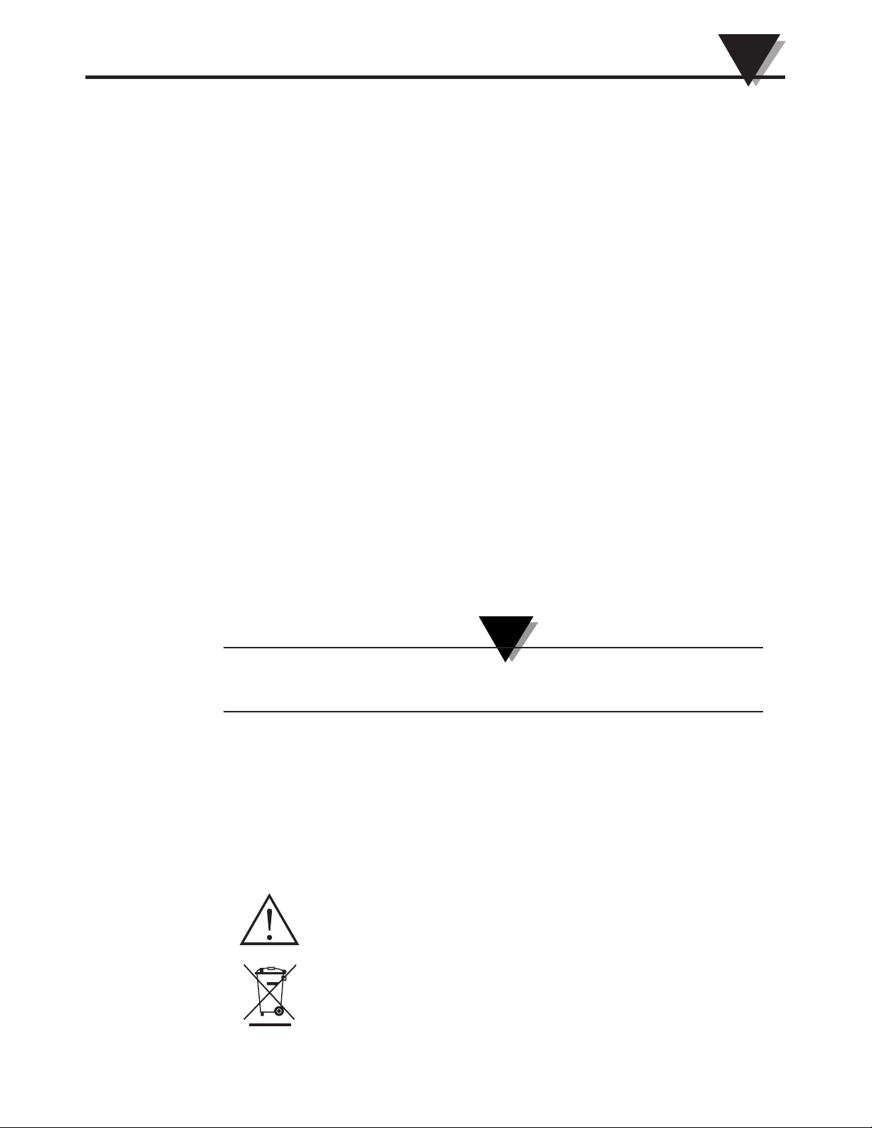
1.3 Product Labeling
1.3.1 Receiver Front Label
Figure 1-2. Receiver Front Label UWTC-REC1-915
1.3.2 Repeater Front Labels
Figure 1-3. Repeater Front Label UWTC-RPT1
1
ANTENNA
USB
I/O
5-12 Vdc
OMEGA ENGINEERING, INC.
Stamford, CT 06907
UWTC SERIES
WIRELESS RF RECEIVER
915 MHz
omega.com
Made in U.S.A.
-
+
!
TX
RX
SB
PWR
This device complies with Part 15 of the FCC rules.
Operation is subject to the following two conditions:
1) This device may not cause harmful interference;
2) This device must accept any interference received,
including interference that may cause undesired
operation.
FCC ID: MCQ–XBEEXSC
IC #1846AA–XBEEXSC
F
®
ANTENNA
ANTENNA
USB
OMEGA ENGINEERING, INC.
Stamford, CT 06907
UWTC SERIES
WIRELESS RF RECEIVER/REPEATER
RECEIVER: 2.4 GHz
TRANSMIT: 915 MHz
omega.com
Made in U.S.A.
TX
RX
SB
PWR
This device complies with Part 15 of the FCC rules.
Operation is subject to the following two conditions:
1) This device may not cause harmful interference;
2) This device must accept any interference received,
including interference that may cause undesired
operation.
RECEIVE
FCC ID: OUR–XBEE
IC #4214A–XBEE
TRANSMIT
FCC ID: MCQ–XBEEXSC
IC #1846A–XBEEXSC
®
5-12 Vdc
-
+
!
Page 9
1-3
Introduction
1
1.4 Statement on FCC and CE Marking
1.4.1 FCC Marking
RECEIVE: FCC ID: OUR-XBEE IC #4214A-XBEE
TRANSMIT: FCC ID: MCQ-XBEEXSC IC#1846A-XBEEXSC
This device complies with Part 15 of the FCC rules. Operation is subject to the
following two conditions: 1.) This device may not cause harmful interference.
2.) This device must accept any interference received, including interference that
may cause undesired operation.
1.4.2 CE Marking
It is the policy of OMEGA
®
to comply with all worldwide safety and EMI/EMC
regulations that apply. OMEGA is constantly pursuing certification of its
products to the European New Approach Directives. OMEGA will add the CE
mark to every appropriate device upon certification. For additional information
see Section 10 - Approvals & Regulatory Compliance.
1.5 General Description & System Components
1.5.1 General Description
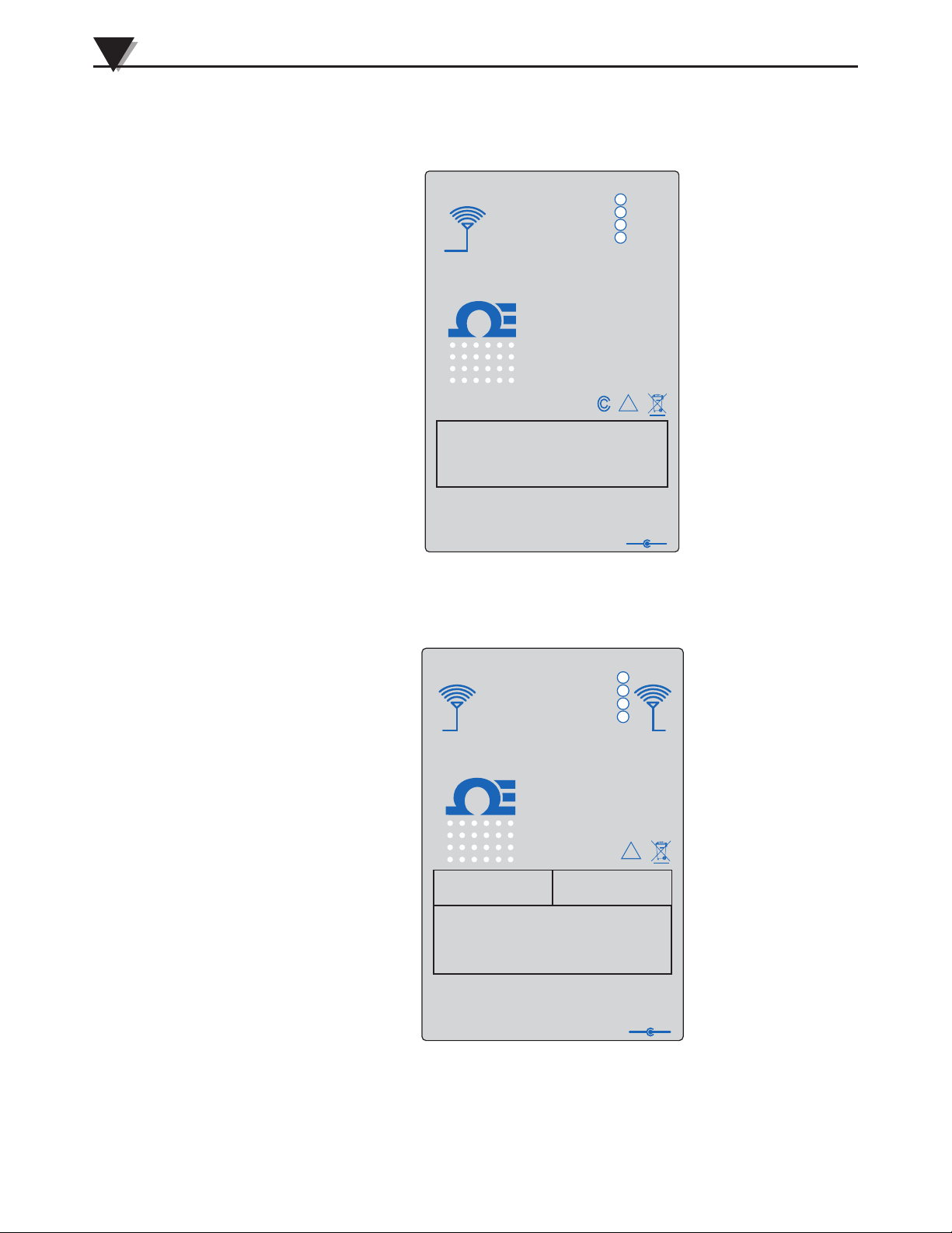
The UWTC-RPT1 long range wireless repeater extends the transmitting range of
the Omega UW Series wireless connectors, probes and industrial transmitters.
The UWTC-RPT1 collects transmitted data from Omega UWTC, UWRTD,
UWIR, UWPH, UWPC, UWRH and UWXL end devices and instantaneously retransmits the data to your USB base receiver. While the standard repeater can
extend the range up to 1.8 miles (3 km), using the repeater with a high-gain
antenna accessory can increase the reading range up to 5 miles (8 km).
The UWTC-RPT1 can only be used with the UWTC-REC1-915 Receiver.
1.5.2 System Components
Figure 1-4. System Components
NOTE:
!
CONNECTOR/TRANSMITTER
REPEATER
RECEIVER
R
UWTC SERIES
WIRELESS RF RECEIVER / REPEATER
OMEGA ENGINEERING INC. omega.com
IC #1846A-XBEEXSC
TX
RX
PWR
SB
Stamford, CT 06907 Made in U.S.A.
USB
FCC ID: MCQ-XBEEXSC
5-12 Vdc
ANTENNA
+
-
ANTENNA
RECEIVE
IC #4214A-XBEEPRO
FCC ID: OUR-XBEEPRO
TRANSMIT
LOW BATT
TX
SETUP
PRESS
PRESS
ON/OFF
UWTC
UNIVERSAL WIRELESS THERMOCOUPLE CONNECTOR
R
This device complies with Part 15 of the FCC rules.
Operation is subject to the following two conditions;
2) This device must accept any interference received,
including interference that may cause undesired
TRANSMIT: 915 MHz
1) This device may not cause harmful interference;
operation.
RECEIVE: 2.4 GHz
ANTENNA
USB
I/O
5-12 Vdc
OMEGA ENGINEERING, INC.
Stamford, CT 06907
UWTC SERIES
WIRELESS RF RECEIVER
915 MHz
omega.com
Made in U.S.A.
-
+
!
TX
RX
SB
PWR
This device complies with Part 15 of the FCC rules.
Operation is subject to the following two conditions:
1) This device may not cause harmful interference;
2) This device must accept any interference received,
including interference that may cause undesired
operation.
FCC ID: MCQ–XBEEXSC
IC #1846AA–XBEEXSC
F
®
Page 10

2-1
NOTE:
Section 2 – Hardware
It is important that you read this manual completely and follow all safety
precautions before operating this instrument.
2.1 Package Inspection
Remove the packing list and verify that you have received all your equipment. If
you have any questions about the shipment, please call our Customer Service
Department at 1-800-622-2378 or 203-359-1660. We can also be reached on the
Internet at omega.com, e-mail: cservice@omega.com. When you receive the
shipment, inspect the container and equipment for any signs of damage. Note
any evidence of rough handling in transit. Immediately report any damage to
the shipping agent.
The carrier will not honor any damage claims unless all shipping material is
saved for inspection. After examining and removing contents, save packing
material and carton in the event reshipment is necessary.
2.2 Included Items
The following items are supplied in the UWTC-RPT1 box:
• 1 Wireless Repeater with two Antennas attached (UWTC-RPT1)
• 1 UWTC-RPT Manual (M4938)
• 1 PC-Based User Software
• 1 AC Wall Adaptor
• 1 USB Programming Cable
2.3 Accessories
The UWTC-RPT1 is offered with the following accessory:
• UWTC-RPT-ANT-900 (or 868): High Gain Antenna, used to increase range of
repeater readings up to 5 miles (8 km).
Please see Section 6.3 for more information
Hardware
2
Page 11
3-1
Software
3
Section 3 – Software
3.1 Getting Started
The following program files are included on the UWTC User Software CD
supplied with your Receiver. These files can also be downloaded from the
omega.com website should you misplace your CD.
• UWTC Connector/Transmitter Setup Utility Program
• UWTC TC-Central Measurement and Data Logging Program
3.2 Software Installation
3.2.1 System Requirements
Your PC should meet the following minimum requirements:
• Pentium Class processor
• Hard Drive Space: 210 meg
• Ram: 256 meg or higher
• 1 Available USB Port
• 1 CD-ROM Drive
• Windows 2000, XB, or Vista (32bit) Operating System
• Adobe Acrobat Reader
3.2.2 Software Installation
Insert the UWTC Series User CD that was included with your receiver unit into
the CD-ROM drive on your PC. Your system should begin the installation
process automatically. If the software installation does not start automatically
please see the “Troubleshooting” Section 7.
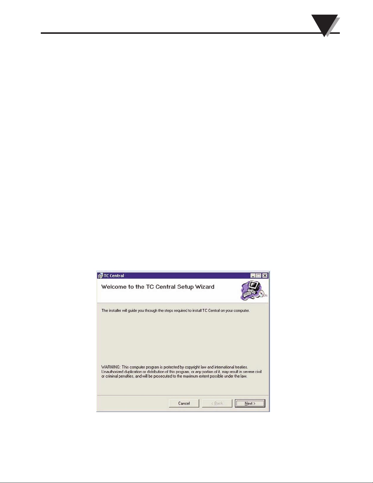
This welcome screen should be visible on your computer screen. To continue
with installing the program click the “Next >” button.
Figure 3-1.
Welcome Screen
Page 12
3-2
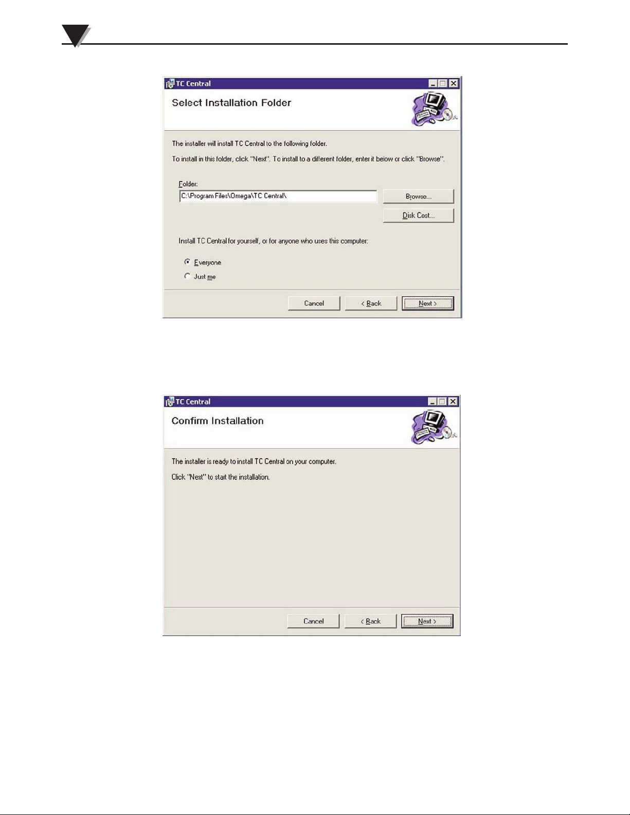
From this screen you select the folder were you want the program files installed
on your PC. The default setting will install the software under your “Program”
folders in a new folder named “Omega” To continue with installing the program
click the “Next >” button.
“Program” folders in a new folder named “Omega” To continue with installing
the program click the “Next >” button.
The setup wizard now has all the information to complete the installation of the
software on your PC. To continue with installing the program click the “Next >”
button.
Figure 3-2.
Select Install Screen
Figure 3-3.
Confirm Installation
Screen
Software
3
Page 13
3-3
Software
3
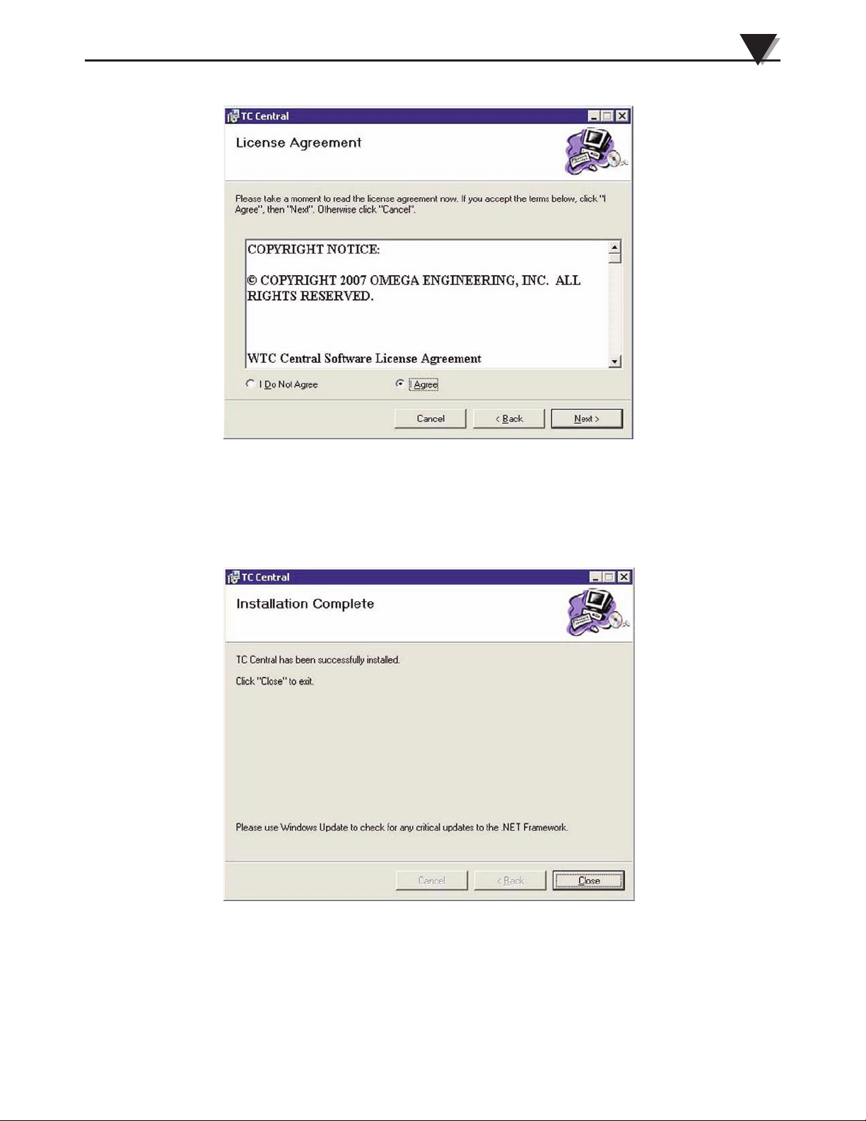
From this screen you must select “Agree” to continue installing your program.
After making your selection click the “Next >” button. The setup wizard will
now install the software.
Congratulations! You have just successfully installed the TC-Central Program on
your PC. To end installing the program and close the setup wizard click the
“Close” Button.
Congratulations! You have just successfully installed the WTC Central Program
on your PC. To end installing the program and close the setup wizard click the
“Close” button.
Figure 3-4.
License Agreement
Screen
Figure 3-5.
Installation
Complete
Screen
Page 14
Software
3
3-4
NOTE:
NOTE:
3.3 USB Driver Installation
To install the USB software drivers that are required for your UWTC system
components to operate correctly follow these procedures.
You need to have the TC-Central User Software CD that was supplied with your
receiver loaded into the CD drive on your PC.
1. Connect your UWTC receiver to your computer with the USB cable
provided in the box with your device. You should get a notice box that
indicates that your computer “Has Found New Hardware”
2. Your computer will then launch the Found New Hardware Wizard. Follow
the instructions indicated on the Wizard boxes and the additional
instructions noted in this manual with each box.
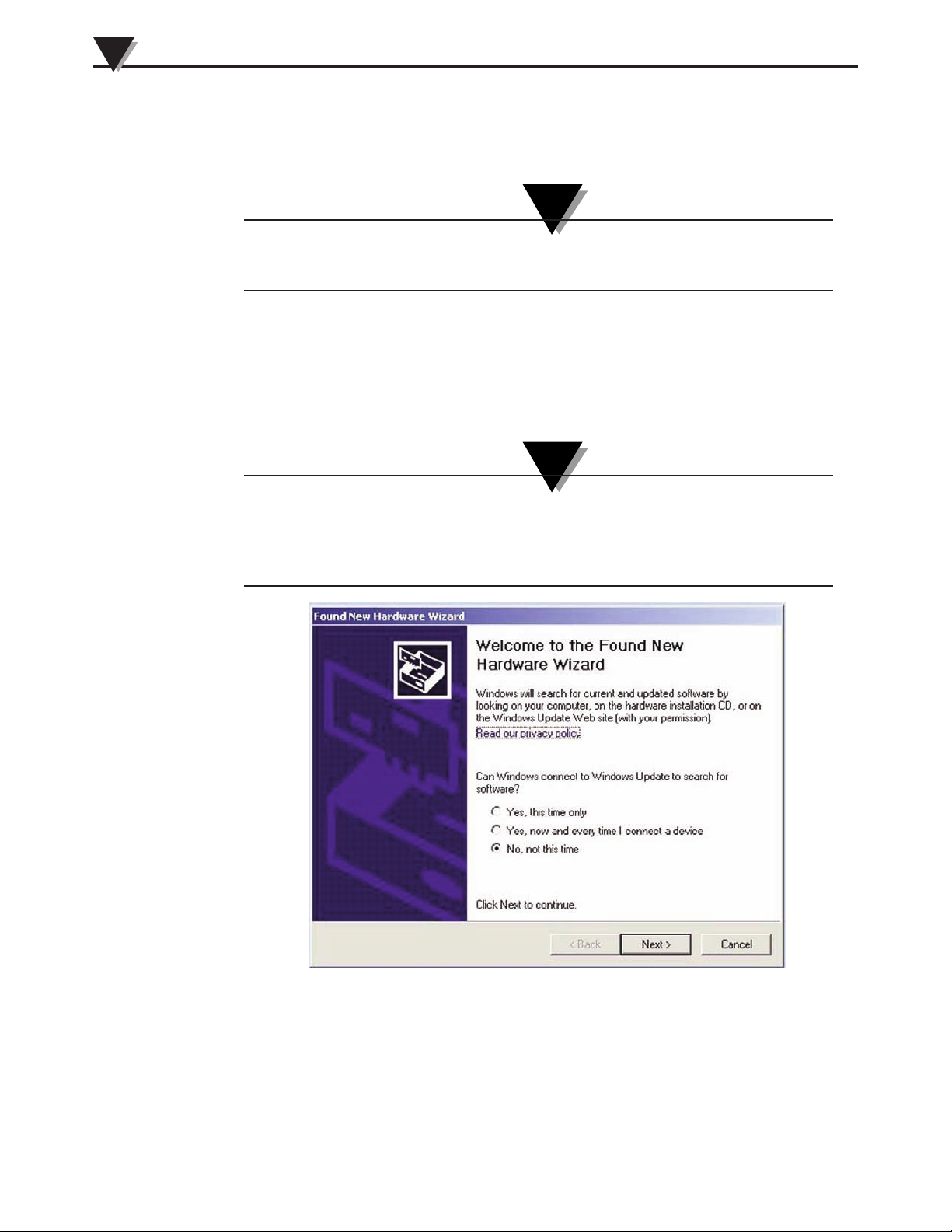
After completing the Found New Hardware Wizard your system will ask that you
repeat this process. This is normal. You should repeat the steps outlined here
twice. After the second driver is installed you should then get the “New Hardware
Ready For Use” notice.
Figure 3-6. Welcome To The Found New Hardware Wizard Screen
From this box you should check the “No, not at this time” button. Then click the
“Next >” button to continue with the driver installation process.
Page 15

Software
3
3-5
Figure 3-7. Install Software Automatically Wizard Screen
Next, check the “Install the software automatically” button. Then click the
“Next>” button to continue.
Figure 3-8. Completing The Found New Hardware Wizard Screen
This screen will be displayed to indicate that the software drivers have been
installed. You should click the “Finish” button to complete the process.
Page 16

3-6
Software
3
Section 3.4 UWTC Connector/Transmitter Setup Utility Program
UWTC TC-Central Measurement and Recording Program
For detailed information on setting up your connector/transmitter, as well as
using the TC-Central Measurement and Recording Program, please refer to the
manual for the connector/transmitter you are using in your long range wireless
system.
Page 17

4-1
Receiver Setup
4
Section 4 - Receiver Setup
Figure 4-1. Receiver Setup - UWTC-REC1-915
4.1 Connecting Your Receiver To Your PC
Connect the USB cable to your receiver unit and also to an available USB port on
your PC. See figure below. This cable was provided in the box with your receiver
unit.
Figure 4-2. Connecting Your Receiver
5-12 Vdc
OMEGA ENGINEERING, INC.
Stamford, CT 06907
omega.com
Made in U.S.A.
-
+
!
This device complies with Part 15 of the FCC rules.
Operation is subject to the following two conditions:
1) This device may not cause harmful interference;
2) This device must accept any interference received,
including interference that may cause undesired
operation.
FCC ID: MCQ–XBEEXSC
IC #1846A–XBEEXSC
®
915 MHz
2.4 GHz
PWR
USB
TX
RX
SB
UWTC SERIES
WIRELESS RF RECEIVER
ANTENNA
REPEATER
915 MHz
2
3
1
Model: UWTC-REC1-915
(1) Antenna
(2) USB Port (mini-B)
(3) Indicator Lights
Connect this end
of your USB cable
to your receiver.
Connect this
end of your
USB cable to
your PC
Page 18

4-2
Section 4.1.1 Configure Your Receiver (UWTC-REC1-915)
To complete this procedure your UWTC-REC1-915 receiver must be connected to
a USB port on your PC. Open TC-Central Software and select "Configure
Receiver" from the TOOLS menu.
RF Network Settings:
RF Channel
This setting determines the operating channel on which RF connections are
made between the transmitter, repeater and receiver. The repeater must be set to
the same channel as the transmitter and receiver in order for them to
communicate.
Network ID
This sets the ID of the Network that the transmitter will be joining. It must
match the setting of the receiver in order for them to communicate.
Receiver Address
This sets the destination address for RF packets sent by the transmitter. It must
match the address of the receiver in order for them to communicate.
It is possible to have multiple RF networks operating in the same vicinity. Each
network must have at least one unique RF Network Setting in order to differentiate
the networks.
Figure 4-3. Configure Receiver Screen
NOTE:
Receiver Setup
4
Page 19

5-1
Repeater Setup
5
Section 5 - Repeater Setup
Figure 5-1. Repeater Operation - Model UWTC-RPT1
(1) Receiving Antenna
(2) USB Port (mini-B)
(3) Indicator Lights
(4) Transmitting Antenna
(5) AC Power
5.1 Connecting Your Repeater to Your PC
Connect the USB cable to your repeater unit and also to an available USB port on
your PC. See figure below. This cable was provided in the box with your repeater
unit.
Figure 5-2. Connecting Your Repeater
Connect this end
of your USB cable
to your repeater.
Connect this
end of your
USB cable to
your PC
2
1
4
ANTENNA
ANTENNA
USB
OMEGA ENGINEERING, INC.
Stamford, CT 06907
UWTC SERIES
WIRELESS RF RECEIVER/REPEATER
RECEIVER: 2.4 GHz
TRANSMIT: 915 MHz
omega.com
Made in U.S.A.
TX
RX
SB
PWR
This device complies with Part 15 of the FCC rules.
Operation is subject to the following two conditions:
1) This device may not cause harmful interference;
2) This device must accept any interference received,
including interference that may cause undesired
operation.
RECEIVE
FCC ID: OUR–XBEE
IC #4214A–XBEE
TRANSMIT
FCC ID: MCQ–XBEEXSC
IC #1846A–XBEEXSC
®
5-12 Vdc
-
+
!
3
5
Page 20

5-2
Repeater Setup
5
5.1.1 Configure Your Repeater
Start the End Device Configuration Wizard or select "Configure End Device"
from the TOOLS menu in TC-Central.
Figure 5-3. Setting Up the End Device
If you have not already placed your End Device into SETUP mode you should
do this now before continuing. After your unit has been placed into the SETUP
mode, click the Next>button to proceed and continue setting up your unit.
Figure 5-4. Establish A Link
The window should show that the Repeater has been detected, and a link has
been established.
Page 21

5-3
Repeater Setup
5
Figure 5-5. Read Settings
Figure 5-6. Choose Options
Choose the RF Network settings for the Repeater. Be sure to match "Receive"
settings to that of the transmitter/connector, and the "Transmit" to that of the
UWTC-REC1-915 receiver.
Page 22

Figure 5-7. Send Setting To End Device
Congratulations! You have successfully programmed your repeater. After your
unit has been programmed click the Finish button to close the utility program.
Repeater Setup
5
5-4
Page 23

NOTES:
Repeater Setup
5
5-5
Page 24

6-1
Section 6 – Repeater Mounting and Installation
6.1 Mounting
Mounting ears are built-in to your repeater enclosure The diagram below shows
dimensions and mounting hole location. Rubber bumpers have also been
supplied with your repeater should you wish to use the device on a desk or a
work bench next to your PC.
When mounting your repeater, care should be taken to make sure it is as far
away from any metal objects. If nearby metal gets too close to your repeater's
antennas, it has the potential to interfere with the way the unit receives and
transmits data and may cause signal lose or possibly even the inability to
communicate at all with your other devices.
Figure 6-1. Mounting Dimensions
Repeater Mounting and Installation
6
!
64mm (2.5")
89mm (3.5")
76 (3.0)
MOUNTING HOLE
CENTER LINE
Ø3.6 (0.140)
Ø7.5 (0.295)
DIMENSIONS mm (in)
R
UWTC SERIES
WIRELESS RF RECEIVER / REPEATER
OMEGA ENGINEERING INC. omega.com
IC #1846A-XBEEXSC
TX
RX
PWR
SB
Stamford, CT 06907 Made in U.S.A.
USB
FCC ID: MCQ-XBEEXSC
5-12 Vdc
ANTENNA
+
-
ANTENNA
RECEIVE
IC #4214A-XBEEPRO
FCC ID: OUR-XBEEPRO
TRANSMIT
This device complies with Part 15 of the FCC rules.
Operation is subject to the following two conditions;
2) This device m
ust accept any interference received,
including interference that m
ay cause undesired
TRANSMIT: 915 MHz
1) This device may not cause harmful interference;
operation.
RECEIVE: 2.4 GHz
Page 25

6-2
Repeater Mounting and Installation
6
6.2 Installation
When installing your repeater it is important to position your device in such a
way as to optimize the antenna location within what’s known as the “Fresnel
Zone”.
The Fresnel Zone can be thought of as a football-shaped invisible tunnel between
two locations that provides a path for RF signals between your
connector/transmitter and your repeater, as well as between your repeater and
receiver.
Figure 6-2. Installation
In order to achieve maximum range, the football-shaped path in which radio
waves travel must be free of all obstructions. Obstacles in the path (especially
metal) will decrease the communication range between your
connector/transmitter, repeater, and receiver. Also, If the antennas are mounted
just barely off the ground, over half of the Fresnel zone ends up being obstructed
by the earth resulting in significant reduction in range. To avoid this problem,
the antennas should be mounted high enough off of the ground so that the earth
does not interfere with the central diameter of the Fresnel zone.
It is important to understand that the environment may change over time due to new
equipment or machinery being installed, building construction, etc. If new obstacles
exist between your connector/transmitter, repeater, and receiver, the devices can be
raised on one end or on all ends to hopefully clear the Fresnel Zone of
obstructions.
Never install UWTC transmitters, repeaters, or receivers within 20cm or less from
each other.
Never use your UWTC repeater as a portable device. Your unit has been
designed to be operated in a permanent installation only.
UWTC
UWTC-RPT-1
UWTC-REC1-915
!
LOW BATT
TX
SETUP
PRESS
PRESS
ON/OFF
UWTC
UNIVERSAL WIRELESS THERMOCOUPLE CONNECTOR
R
R
UWTC SERIES
WIRELESS RF RECEIVER / REPEATER
OMEGA ENGINEERING INC. omega.com
IC #1846A-XBEEXSC
TX
RX
PWR
SB
Stamford, CT 06907 Made in U.S.A.
USB
FCC ID: MCQ-XBEEXSC
9-24 Vdc
ANTENNA
+
-
ANTENNA
RECEIVE
IC #4214A-XBEEPRO
FCC ID: OUR-XBEEPRO
TRANSMIT
This device complies with Part 15 of the FCC rules.
Operation is subject to the following two conditions;
2) This device must accept any interference received,
including interference that may cause undesired
TRANSMIT: 915 MHz
1) This device may not cause harmful interference;
operation.
RECEIVE: 2.4 GHz
NOTE:
NOTE:
NOTE:
Page 26

6-3
Repeater Mounting and Installation
5
6.3 Antenna Connection
Your repeater has been shipped to you with two antennas. Attach the 2.4 GHz
shorter antenna on the left side of the unit and the longer 915/868 MHz antenna
on the right side of the unit.
In the case that you want to improve range and signal strength for your repeater,
you may replace your antenna with a high gain antenna (Omega Model No.
RPT-HGA-915/868). This antenna is sold as an accessory.
No co-location with other radio transmitters is allowed. By definition, co-location
is when another radio device or its antenna is located within 20cm of your
connector/transmitter or repeater and can transmit simultaneously with your
UWTC unit.
The Omega High Gain Antenna is used to increase the transmitting range from
the repeater to the receiver.
On your repeater, the antenna on the left receives data from the transmitter; the
antenna on the right side transmits that data to the receiver. It is the antenna on
the right side of the repeater that needs to be replaced with your High Gain
Antenna.
Figure 6-3. Standard Repeater Antennas
!
915/868 MHz
TRANSMITTING
ANTENNA
2.4 GHz
RECEIVING
ANTENNA
R
UWTC SERIES
WIRELESS RF RECEIVER / REPEATER
OMEGA ENGINEERING INC. omega.com
IC #1846A-XBEEXSC
TX
RX
PWR
SB
Stamford, CT 06907 Made in U.S.A.
USB
FCC ID: MCQ-XBEEXSC
5-12 Vdc
ANTENNA
+
-
ANTENNA
RECEIVE
IC #4214A-XBEEPRO
FCC ID: OUR-XBEEPRO
TRANSMIT
This device complies with Part 15 of the FCC rules.
Operation is subject to the following two conditions;
2) This device must accept any interference received,
including interference that may cause undesired
TRANSMIT: 915 MHz
1) This device may not cause harmful interference;
operation.
RECEIVE: 2.4 GHz
NOTE:
Page 27

6-4
Repeater Mounting and Installation
5
On your receiver, there is only one antenna. This must also be replaced with a
High Gain Antenna in order for the range to be increased.
Figure 6-4. Receiver Antenna
Once you have replaced both antennas, the range increase is complete.
In order for the system to work properly, you must use a High Gain Antenna on
both the repeater and the receiver.
Use of any other antenna than what’s supplied with your device will void all FCC
and CE regulatory compliance.
Additional Information on installation and system operation can be found in
Section 6.
NOTE:
NOTE:
RECEIVING
ANTENNA
5-12 Vdc
OMEGA ENGINEERING, INC.
Stamford, CT 06907
omega.com
Made in U.S.A.
-
+
!
This device complies with Part 15 of the FCC rules.
Operation is subject to the following two conditions:
1) This device may not cause harmful interference;
2) This device must accept any interference received,
including interference that may cause undesired
operation.
FCC ID: MCQ–XBEEXSC
IC #1846A–XBEEXSC
®
PWR
USB
TX
RX
SB
UWTC SERIES
WIRELESS RF RECEIVER
ANTENNA
915 MHz
Page 28

NOTES:
Repeater Mounting and Installation
5
6-5
Page 29

7-1
System Operation
7
Section 7 - System Operation
7.1 Introduction
Compared to wired systems, wireless systems provide much simpler
installation. Based on the physical principle of the propagation of radio waves,
certain basic conditions should be observed. The following simple
recommendations are provided to insure proper installation and correct
operation of your UWTC Series system.
7.2 RF Communication Basics
In a basic UWTC series system, the UW series transmitter sends wireless
transmissions to the UWTC-REC1-915 receiver. The receiver checks the incoming
data for accuracy and processes this data for use by the measurement software
on your PC. Radio signals are electromagnetic waves; hence the signal becomes
weaker the further it travels. While radio waves can penetrate some solid
materials like a wall, they are dampened more than when a direct line-of-sight
between the transmitting and receiving antenna exist.
With the UWTC-RPT1 repeater in your UWTC series system, you are able to
maintain a strong signal over a long distance. The UW series transmitter sends
wireless transmissions to the UWTC-RPT1 repeater. The repeater serves as a
signal extension; it receives the incoming data and transmits it to the receiver.
The receiver then checks the incoming data for accuracy and processes it for use
on your measurement software.
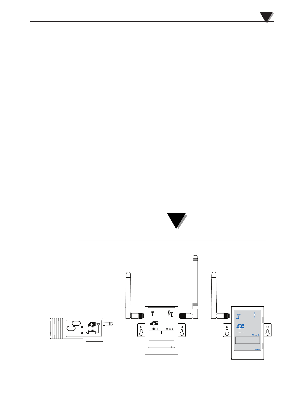
7.3 Basic System Overview
Figure 7-1. Basic System Overview
The UWTC wireless thermocouple system is comprised of three main
components; a Thermocouple Connector (with a built-in battery powered 2.4
GHz radio transmitter), a Wireless Repeater (with a 2.4 GHZ receiver and 915
MHz transmitter), and a USB powered 915 MHz receiver.
Up to 48 of each Model UWTC connector/transmitters can be used with one
UWTC-RPT1 repeater.
UWTC
UWTC-RPT-1
UWTC-REC1-915
UWTC
UWTC
!
LOW BATT
TX
SETUP
PRESS
PRESS
ON/OFF
UWTC
UNIVERSAL WIRELESS THERMOCOUPLE CONNECTOR
R
LOW BATT
TX
SETUP
PRESS
PRESS
ON/OFF
UWTC
UNIVERSAL WIRELESS THERMOCOUPLE CONNECTOR
R
LOW BATT
TX
SETUP
PRESS
PRESS
ON/OFF
UWTC
UNIVERSAL WIRELESS THERMOCOUPLE CONNECTOR
R
R
UWTC SERIES
WIRELESS RF RECEIVER / REPEATER
OMEGA ENGINEERING INC. omega.com
IC #1846A-XBEEXSC
TX
RX
PWR
SB
Stamford, CT 06907 Made in U.S.A.
USB
FCC ID: MCQ-XBEEXSC
9-24 Vdc
ANTENNA
+
-
ANTENNA
RECEIVE
IC #4214A-XBEEPRO
FCC ID: OUR-XBEEPRO
TRANSMIT
This device complies with Part 15 of the FCC rules.
Operation is subject to the following two conditions;
2) This device must accept any interference received,
including interference that may cause undesired
TRANSMIT: 915 MHz
1) This device may not cause harmful interference;
operation.
RECEIVE: 2.4 GHz
Page 30

NOTE:
7.4 Connector/Transmitter Operation
7.4.1 Button Operation
(1.) “PRESS ON/OFF”
The “PRESS ON/OFF” button on the front of your connector/transmitter is used
to turn your unit “ON” or “OFF”
(2.) “PRESS SETUP”
The “PRESS SETUP” button on the front of your connector/transmitter is only
used during the setup and configuration of your unit. See Section 4.1.2 for more
information.
Figure 7-2. Connector/Transmitter Button Operation
7.4.2 Ambient Temperature Readings
The ambient temperature reading displayed on your screen when running the
TC-Central program, is the actual ambient temperature that your
connector/transmitter is being exposed to. This reading is only provided as
reference and to aid you in proper installation of your unit. The ambient
temperature reading will blink and change to RED digits to alert you that your
have exceed the maximum recommended safe operating conditions for your
connector/transmitter. You should not rely on this feature as sole protection.
Additional protection should be taken by you “the user” to protect your unit
from extreme conditions.
Operating your connector/transmitter outside the specified ambient conditions
listed in Section 9 of this manual may cause your unit to malfunction and stop
working correctly.
7.4.3 Indicator Lights
(1) Transmit (TX) Green Indicator Light
The green indicator light marked “TX” on the front of the connector/transmitter
will blink every time the unit sends data to the receiving unit. Example; If you
selected a 5 sec sample rate the green TX led will blink one time every 5 seconds.
(2) Low Battery (Low Bat) Red Indicator Light
The red indicator light marked “Low Bat” on the front of the
connector/transmitter will turn on when the battery reaches a level at or below
the power level required for normal operation. When this indicator turns on it’s
time to install a fresh battery in your unit. For procedures on how to change your
battery see Section 4.5. For information on battery life see Section 6.11.
1
2
®
TX
UNIVERSAL WIRELESS THERMOCOUPLE CONNECTOR
LOW BATT
PRESS
SETUP
PRESS
ON/OFF
UWTC
7-2
System Operation
7
Page 31

7-3
System Operation
7
Figure 7-3. Transmit and Low Battery Lights
7.5 Repeater Operation
7.5.1 Indicator Lights
(1) Transmit (TX) Green Indicator Light
The top green indicator light marked “TX” on the front of the repeater will only
blink when the repeater is connected to your PC and you initialize your
measurement software. After the repeater establishes communication with the
program the light will no longer blink. Note: This may happen very fast and will
not be noticeable.
(2) Receive (RX) Red Indicator Light
The red indicator light marked “RX” on the front of your repeater will blink each
time the repeater receives incoming data from one of your
connector/transmitters.
(3) Standby (SB) Yellow Indicator Light
The yellow indicator light marked “SB” on the front of the receiver will blink
continuously during normal operation. This indicates that the repeater is in the
“Standby” mode and is waiting for incoming data from your
connector/transmitter.
(4) Power (PWR) Green Indicator Light
7.6 Receiver Operation
7.6.1 Indicator Lights
(1) Transmit (TX) Green Indicator Light
The top green indicator light marked “TX” on the front of the receiver will only
blink when the receiver is connected to your PC and you initialize your
measurement software. After the receiver establishes communication with the
program the light will no longer blink. Note: this may happen very fast and will
not be noticeable.
(2) Receive (RX) Red Indicator Light
The red indicator light marked “RX” on the front of the receiver will blink each
time the receiver receives incoming data from one of your connector
transmitters.
(3) Standby (SB) Yellow Indicator Light
The yellow indicator light marked “SB” on the front of the receiver will blink
continuously during normal operation. This indicates that the receiver is in the
®
TX
UNIVERSAL WIRELESS THERMOCOUPLE CONNECTOR
LOW BATT
PRESS
SETUP
PRESS
ON/OFF
UWTC
1
2
Page 32

“Standby” mode and is waiting for incoming data from your
connector/transmitter.
(4) Power (PWR) Green Indicator Light
Figure 7-4. Indicator Lights
7.7 Environment/Operating Conditions
7.7.1 Environment
Omega’s UWTC or UWRTD series connector/transmitter, repeater, and receiver
units have been designed to be fixed mounted and operated in a clean and dry
indoor environment. Care should be taken to prevent the components of your
wireless system from being exposed to moisture, toxic chemicals and extreme
cold or hot temperature that are outside the specifications listed in this manual.
7.7.2 Operating Conditions
The following is a list of basic good practice you should apply when operating
your wireless system.
• Never operate your wireless device outside the recommended
environmental limits specified in this manual.
• Never operate your wireless device in flammable or explosive
environments.
• Never use your wireless device in medical, nuclear or other dangerous
applications were failure can cause damage or harm.
• Never operate your repeater with any other power source than what’s
specified in this manual.
• No co-location with other radio transmitters is allowed. By definition, colocation is when another radio device or it’s antenna is located within 20 cm
of your connector/transmitter or repeater and can transmit simultaneously
with your UWTC unit.
• Never install a your devices within 20 cm or less from each other.
• Never use your repeater as a portable device. Your unit has been designed to
be operated in a permanent installation.
• Never install and/or operate your devices closer than 20 cm to nearby
persons.
• Never operate your repeater with any other antenna than what is supplied
or listed here in this manual for approved use.
1
2
SB
PWR
RX
TX
3
4
7-4
System Operation
7
Page 33

7-5
System Operation
7
NOTE:
7.8 Determining and Maximizing Range
The available maximum range specified for the wireless Series system in this
manual is only achievable under optimum installation conditions. Mounting
height, obstructions in your “Fresnel Zone” and ambient conditions can cause a
decrease in signal strength resulting in a shorter range between your
transmitter/connector and receiver unit.
The following recommendations will help to improve the range of your wireless
system.
• Place your repeater in a space equidistant between the transmitter and the
receiver.
• When using the repeater in addition to the multiple connectors/transmitters,
position your repeater in a central space if possible in equal distance
between the connector/transmitters and your receiver.
Figure 7-5. Determining Maximum Range
Test your system before permanent mounting
Before permanently mounting your connector/transmitters in your application
try moving the devices to different locations and mounting angles to determine
what installation achieves the best signal strength.
Move your system components higher off the floor and away from exterior walls
Avoid installing your system components too close to the floor or near your
buildings exterior walls. The closer your connector/transmitter and receiver unit
are the greater the interference and loss of signal strength will be.
UWTC-1
UWTC-RPT-1
UWTC-RPT-1
UWTC-REC1
UWTC-1
UWTC-1
UWTC-1
UWTC-1
CONTROL ROOM
BLDG. 1
BLDG. 2
BLDG. 3
BLDG. 4
Page 34

Maintain a line of sight (LOS) between antennas
Maintaining a line of sight between your connector/transmitter and receiver
unit will produce greatly improved signal strength over a system were the
antennas in your system have obstacles blocking them.
Maintain a constant ambient temperature environment
Maintaining a constant ambient temperature environment is important to
achieving maximum signal strength. Exposing your system components to
extreme hold or cold temperatures, or sudden changes in ambient conditions
will have an effect on the performance of your system.
7.8.1 Operation in Buildings
Your Connector/Transmitter sends wireless data transmissions to a receiver
connected to your PC. Radio signals are electromagnetic waves. A radio signal
becomes weaker the further it travels. Range is decreased by different types of
materials found in the direction of the signals propagation. Radio waves can
penetrate most types of wall materials, but they are dampened more than they
would be by a direct line-of-sight installation.
7.8.2 Building Materials
Examples of how different types of wall material may reduce your signal:
Material Type Possible Signal Reduction
Wood, Plaster, Sheetrock, Uncoated 0 to 10%
Glass w/o Metal, Fiberglass
Brick, Pressboard 5 to 35%
Reinforced Concrete 10 to 90%
Metal Walls, Metal Doors, Elevators,
Metal Stair Cases, Metal Piping, 90 to 100%
Metal Mesh, Metal Screening
Figure 7-6. Operation In Buildings
Avoid dampening materials by repositioning the connector/transmitting and/or
receiver.
7.8.3. Penetration Angle of Radio Waves Through Walls
The angle at which the transmitted radio signal hits a wall is very important and
also has a big effect on maximizing range. Signals between your
connector/transmitter should be transmitted as directly as possible.
7-6
System Operation
7
Page 35

7-7
System Operation
7
NOTE:
NOTE:
7.9 Antenna Basics
7.9.1 Antenna Basics
By definition, an antenna is a device used to transform an RF signal, traveling on
a conductor, into an electromagnetic wave in free space. Antennas demonstrate a
property known as reciprocity, this means that an antenna will always maintain
the same characteristics regardless if it is used to transmit or receive. Most
antennas are resonant devices, which means they operate efficiently over a
relatively very narrow frequency band. An antenna must be tuned to the same
frequency band of the radio system to which it is connected, otherwise the
reception and the transmission will be impaired.
The antennas in your wireless repeater have been tuned to operate in the 2.4
GHz band to receive, and the 915 MHz band to transmit information.
In some cases, a short RF cable may be used to connect an antenna to your device.
Please note that RF extension cables will always add some loss to the transmitting
signal strength. The longer the cable the more signal will be lost over that cable.
Because of this the length of the cable should be kept as short as possible.
7.10 Antenna Placement
Proper antenna installation is important and will allow you to achieve maximum
performance and range between your connector/transmitter, repeater, and
receiver unit.
Your connector/transmitter should not be installed on the same side of the wall as the
receiver. If mounted close to each other on the same wall, the radio waves are likely to
be subject to interfering dispersions or reflections. The best positioning is to have the
connector/transmitter installed on the opposite or connecting wall to the receiver.
7.10.1 Horizontal Antenna Placement
Figure 7-7. Horizontal Antenna Placement
If your Connector/Transmitter is mounded in a horizontal position in your
application you should mount your receiving so that the same polarization is
achieved with the corresponding receiving antenna. As shown in the “Horizontal”
example above.
!
LOW BATT
TX
SETUP
PRESS
PRESS
ON/OFF
UWTC
UNIVERSAL WIRELESS THERMOCOUPLE CONNECTOR
R
R
UWTC SERIES
WIRELESS RF RECEIVER / REPEATER
OMEGA ENGINEERING INC. omega.com
IC #1846A-XBEEXSC
TX
RX
PWR
SB
Stamford, CT 06907 Made in U.S.A.
USB
FCC ID: MCQ-XBEEXSC
9-24 Vdc
ANTENNA
+
-
ANTENNA
RECEIVE
IC #4214A-XBEEPRO
FCC ID: OUR-XBEEPRO
TRANSMIT
This device complies with Part 15 of the FCC rules.
Operation is subject to the following two conditions;
2) This device must accept any interference received,
including interference that may cause undesired
TRANSMIT: 915 MHz
1) This device may not cause harmful interference;
operation.
RECEIVE: 2.4 GHz
ANTENNA
USB
I/O
5-12 Vdc
OMEGA ENGINEERING, INC.
Stamford, CT 06907
UWTC SERIES
WIRELESS RF RECEIVER
915 MHz
omega.com
Made in U.S.A.
-
+
!
TX
RX
SB
PWR
This device complies with Part 15 of the FCC rules.
Operation is subject to the following two conditions:
1) This device may not cause harmful interference;
2) This device must accept any interference received,
including interference that may cause undesired
operation.
FCC ID: MCQ–XBEEXSC
IC #1846AA–XBEEXSC
F
®
Page 36

7.10.2 Vertical Antenna Placement
If your Connector/Transmitter is mounded in a vertical position in your
application you should mount your receiving so that the same polarization is
achieved with the corresponding receiving antenna. As shown in the “Vertical”
example Fig 7-8.
Figure 7-8. Vertical Antenna Placement
7.11 Factory Preset Values
Your Connector/Transmitter has been factory programmed for the following
default operation; Channel Number: 1, Thermocouple Type: K, Transmit Rate: 1
sample/5 sec
Your wireless repeater has been factory programmed for the following default
operation:
2.4 GHz Receiver: RF Channel: 12
Network ID: 13106
Receiver Address: 0
915 MHz Transceiver: RF Channel: 0
Network ID: 13106
Receiver Address: 0
868 MHz Transceiver: RF Channel: 0
Network ID: 32767
Receiver Address: 0
7-8
System Operation
7
!
LOW BATT
TX
SETUP
PRESS
PRESS
ON/OFF
UWTC
UNIVERSAL WIRELESS THERMOCOUPLE CONNECTOR
R
R
UWTC SERIES
WIRELESS RF RECEIVER / REPEATER
OMEGA ENGINEERING INC. omega.com
IC #1846A-XBEEXSC
TX
RX
PWR
SB
Stamford, CT 06907 Made in U.S.A.
USB
FCC ID: MCQ-XBEEXSC
9-24 Vdc
ANTENNA
+
-
ANTENNA
RECEIVE
IC #4214A-XBEEPRO
FCC ID: OUR-XBEEPRO
TRANSMIT
This device complies with Part 15 of the FCC rules.
Operation is subject to the following two conditions;
2) This device must accept any interference received,
including interference that may cause undesired
TRANSMIT: 915 MHz
1) This device may not cause harmful interference;
operation.
RECEIVE: 2.4 GHz
ANTENNA
USB
I/O
5-12 Vdc
OMEGA ENGINEERING, INC.
Stamford, CT 06907
UWTC SERIES
WIRELESS RF RECEIVER
915 MHz
omega.com
Made in U.S.A.
-
+
!
TX
RX
SB
PWR
This device complies with Part 15 of the FCC rules.
Operation is subject to the following two conditions:
1) This device may not cause harmful interference;
2) This device must accept any interference received,
including interference that may cause undesired
operation.
FCC ID: MCQ–XBEEXSC
IC #1846AA–XBEEXSC
F
®
Page 37

NOTES:
System Operation
7
7-9
Page 38

NOTES:
7-10
UTWC-RPT1 - Long Range Wireless
Repeater/Receiver System For UW Series Transmitters
Page 39

Troubleshooting
8-1
Section 8 - Troubleshooting
The information provided in this section should solve most of the common
problems you may experience when installing or operating your wireless
System. If the problems and solutions outlined here do not solve your problem,
please contact Omega’s customer service department. Contact information can
be found in Section 2 of this manual or by visiting omega.com.
8.1 Connector/Transmitter Troubleshooting
Problem Solution
1. Unit will not enter “Setup” mode a. Check USB cable connection
b. Contact Customer Service
2. Configuration Utility will not connect a. Check USB cable connection
to device being programmed
b. Confirm you are in the
“SETUP”mode. See Section 3
c. Contact Customer Service
8.2 Receiver Troubleshooting
Problem Solution
1. Unit will not turn on a. Check power cord
connections
b. Unit requires service, contact
Customer Service
8
Page 40

Service and Calibration
9-1
Section 9 – Service & Calibration
Your UWTC and UWRTD Series components have been built and factory
calibrated to meet or exceed the specifications listed here in this manual. The
following two sub-sections provide information on how to have your device
serviced and also on how to re-calibrate your unit in the field.
9.1 Service & Calibration
If any of your wireless system components require service or calibration, please
call our Customer Service Department at 1-800-622-2378 or 203-359-1660. They
will assist you in arranging the return and service of your device. We can also be
reached on the Internet at www.omega.com, e-mail: cservice@omega.com
9
Page 41

Specifications
10-1
Section 10 – Specifications
10.1 Repeater Specifications
Power: 5-12Vdc @ 500 mA (AC wall adapter included)
Ambient Operating Conditions: 0 to 55°C (32 to 131°F), 90% RH non-
condensing
Wireless Communication
Receiving Frequency: 2.4 GHz
Transmitting Frequency: 915 MHz (USA/Canada), 868 MHz (Europe)
RF Transmit Power: 100 mW (+20 dBm)
Indoor/Urban Range: Up to 1000 ft (305 m)
Outdoor/RF
Line-of-sight Range: Up to 1.8 miles (8 km), up to 5 miles (8 km)
with optional high gain antenna
Setup & Configuration: USB (cable included) for Windows 2000, XP,
Vista or Windows 7 operating system.
Enclosure
Standard Model: Painted Steel
NEMA Model: ABS Base, Polycarbonate Lid
Dimensions
Standard Model: 92 H x 62 W x 22 mm D (3.6 x 2.43 x .85")
NEMA Model: 160 H x 90 W x 60 mm D (6.3 x 3.54 x 2.36")
Approvals: FCC, IC, CE
10
Page 42

Section 11 – Approvals, Regulatory Compliance & Patent Notice
All approvals outlined in this manual are based on testing that was done with
antennas that are supplied with your wireless Series System Components.
Removing and or installing a different antea will void the product compliance
demonstrated in these documents.
11.1 FCC (Domestic Use: USA & Canada)
RECEIVE: FCC ID: OUR-XBEE IC #4214A-XBEE
TRANSMIT: FCC ID: MCQ-XBEEXSC IC#1846A-XBEEXSC
This device complies with Part 15 of the FCC rules. Operation is subject to the
following two conditions: 1.) This device may not cause harmful interference.
2.) This device must accept any interference received, including interference that
may cause undesired operation.
To satisfy FCC RF exposure requirements for mobile transmitting devices, a separation
distance of 20 cm or more should be maintained between the antenna of this device
and persons during device operation. To ensure compliance, operations at closer
than this distance is not recommended. The antenna used for this transmitter must not
be co-located in conjunction with any other antenna or transmitter.
11.2 International Usage & CE Marking (Pending)
The UWTC and UWRTD Series system components are CE marked and certified
for use in several European countries. Please contact OMEGA for information on
International Regulatory Compliance for each country.
It is your (the user’s) responsibility to insure that these products are operated
within the guidelines here in this manual and in conformance with all local or
national regulations and laws.
Transmitting Power
Your UWTC and UWRTD Series System Components have been designed and
manufactured so that the transmitting power will not exceed 2 dBm (10 mW).
11.3 Declaration of Conformity (DOC)
Contact OMEGA for status on CE marking and DOC availability.
11.4 Patent Notice
(Product is covered by patents for Super MCJ, Uniconnector and pending wireless connector)
PATENT NOTICE: U.S. PAT. NO. 6,074,089 / Canada 2,228,333; 1,288,142 / UK GB 2,321,712;
2,193,048 / Holland 1008153 / Israel 123052 / France 2 762 908 / Germany 19803351.6
Other U.S. and international patents pending.
NOTE:
WARNING:
11-1
UWTC PATENT NOTICE
Approvals, Regulatory Compliance & Patent Notice
11
Page 43

WARRANTY/DISCLAIMER
OMEGA ENGINEERING, INC. warrants this unit to be free of defects in materials and workmanship for a
period of 13 months from date of purchase. OMEGA’s WARRANTY adds an additional one (1) month
grace period to the normal one (1) year product warranty to cover handling and shipping time. This
ensures that OMEGA’s customers receive maximum coverage on each product.
If the unit malfunctions, it must be returned to the factory for evaluation. OMEGA’s Customer Service
Department will issue an Authorized Return (AR) number immediately upon phone or written request.
Upon examination by OMEGA, if the unit is found to be defective, it will be repaired or replaced at no
charge. OMEGA’s WARRANTY does not apply to defects resulting from any action of the purchaser,
including but not limited to mishandling, improper interfacing, operation outside of design limits,
improper repair, or unauthorized modification. This WARRANTY is VOID if the unit shows evidence of
having been tampered with or shows evidence of having been damaged as a result of excessive corrosion;
or current, heat, moisture or vibration; improper specification; misapplication; misuse or other operating
conditions outside of OMEGA’s control. Components in which wear is not warranted, include but are not
limited to contact points, fuses, and triacs.
OMEGA is pleased to offer suggestions on the use of its various products. However,
OMEGA neither assumes responsibility for any omissions or errors nor assumes liability for any
damages that result from the use of its products in accordance with information provided by
OMEGA, either verbal or written. OMEGA warrants only that the parts manufactured by the
company will be as specified and free of defects. OMEGA MAKES NO OTHER WARRANTIES OR
REPRESENTATIONS OF ANY KIND WHATSOEVER, EXPRESSED OR IMPLIED, EXCEPT THAT OF
TITLE, AND ALL IMPLIED WARRANTIES INCLUDING ANY WARRANTY OF MERCHANTABILITY
AND FITNESS FOR A PARTICULAR PURPOSE ARE HEREBY DISCLAIMED. LIMITATION OF
LIABILITY: The remedies of purchaser set forth herein are exclusive, and the total liability of
OMEGA with respect to this order, whether based on contract, warranty, negligence,
indemnification, strict liability or otherwise, shall not exceed the purchase price of the
component upon which liability is based. In no event shall OMEGA be liable for
consequential, incidental or special damages.
CONDITIONS: Equipment sold by OMEGA is not intended to be used, nor shall it be used: (1) as a “Basic
Component” under 10 CFR 21 (NRC), used in or with any nuclear installation or activity; or (2) in medical
applications or used on humans. Should any Product(s) be used in or with any nuclear installation or
activity, medical application, used on humans, or misused in any way, OMEGA assumes no responsibility
as set forth in our basic WARRANTY/DISCLAIMER language, and, additionally, purchaser will indemnify
OMEGA and hold OMEGA harmless from any liability or damage whatsoever arising out of the use of the
Product(s) in such a manner.
RETURN REQUESTS/INQUIRIES
Direct all warranty and repair requests/inquiries to the OMEGA Customer Service Department. BEFORE
RETURNING ANY PRODUCT(S) TO OMEGA, PURCHASER MUST OBTAIN AN AUTHORIZED RETURN
(AR) NUMBER FROM OMEGA’S CUSTOMER SERVICE DEPARTMENT (IN ORDER TO AVOID
PROCESSING DELAYS). The assigned AR number should then be marked on the outside of the return
package and on any correspondence.
The purchaser is responsible for shipping charges, freight, insurance and proper packaging to prevent
breakage in transit.
FOR WARRANTY
RETURNS, please have the
following information available BEFORE
contacting OMEGA:
1. Purchase Order number under which the product
was PURCHASED,
2. Model and serial number of the product under
warranty, and
3. Repair instructions and/or specific problems
relative to the product.
FOR NON-WARRANTY REPAIRS,
consult OMEGA
for current repair charges. Have the following
information available BEFORE contacting OMEGA:
1. Purchase Order number to cover the COST
of the repair,
2. Model and serial number of the product, and
3. Repair instructions and/or specific problems
relative to the product.
OMEGA’s policy is to make running changes, not model changes, whenever an improvement is possible. This affords
our customers the latest in technology and engineering.
OMEGA is a registered trademark of OMEGA ENGINEERING, INC.
© Copyright 2010 OMEGA ENGINEERING, INC. All rights reserved. This document may not be copied, photocopied,
reproduced, translated, or reduced to any electronic medium or machine-readable form, in whole or in part, without the
prior written consent of OMEGA ENGINEERING, INC.
Page 44

M4938/0810
Where Do I Find Everything I Need for
Process Measurement and Control?
OMEGA…Of Course!
Shop online at omega.com
SM
TEMPERATURE
䡺⻬
Thermocouple, RTD & Thermistor Probes, Connectors, Panels & Assemblies
䡺⻬
Wire: Thermocouple, RTD & Thermistor
䡺⻬
Calibrators & Ice Point References
䡺⻬
Recorders, Controllers & Process Monitors
䡺⻬
Infrared Pyrometers
PRESSURE, STRAIN AND FORCE
䡺⻬
Transducers & Strain Gages
䡺⻬
Load Cells & Pressure Gages
䡺⻬
Displacement Transducers
䡺⻬
Instrumentation & Accessories
FLOW/LEVEL
䡺⻬
Rotameters, Gas Mass Flowmeters & Flow Computers
䡺⻬
Air Velocity Indicators
䡺⻬
Turbine/Paddlewheel Systems
䡺⻬
Totalizers & Batch Controllers
pH/CONDUCTIVITY
䡺⻬
pH Electrodes, Testers & Accessories
䡺⻬
Benchtop/Laboratory Meters
䡺⻬
Controllers, Calibrators, Simulators & Pumps
䡺⻬
Industrial pH & Conductivity Equipment
DATA ACQUISITION
䡺⻬
Data Acquisition & Engineering Software
䡺⻬
Communications-Based Acquisition Systems
䡺⻬
Plug-in Cards for Apple, IBM & Compatibles
䡺⻬
Data Logging Systems
䡺⻬
Recorders, Printers & Plotters
HEATERS
䡺⻬
Heating Cable
䡺⻬
Cartridge & Strip Heaters
䡺⻬
Immersion & Band Heaters
䡺⻬
Flexible Heaters
䡺⻬
Laboratory Heaters
ENVIRONMENTAL
MONITORING AND CONTROL
䡺⻬
Metering & Control Instrumentation
䡺⻬
Refractometers
䡺⻬
Pumps & Tubing
䡺⻬
Air, Soil & Water Monitors
䡺⻬
Industrial Water & Wastewater Treatment
䡺⻬
pH, Conductivity & Dissolved Oxygen Instruments
 Loading...