

Page 1
Operating instructions
Torque transducer type AE
with replaceable strain gauge measuring element
Model TQ 505
Operating instructions no. 1079
Torque Transducer TQ 505
Page 1 / 16
Page 2

1. Contents
1. List of contents.....................................................................................................page 2
2. Application and typical features....................................................................................... 3
3. Description of the measuring system............................................................................... 4
3.1 Mechanical design ......................................................................................................4
3.2 Electrical design.......................................................................................................... 5
3.2.1 Electrical design of speed measurement.................................................................... 6
4. Electrical connection of the torque transducer................................................................. 7
4.1 Power supply............................................................................................................... 7
4.2 Connection assignment for torque transducers.......................................................... 8
4.3 Connection assignment for speed pick-up ................................................................. 9
4.4 Installing the measuring cable .................................................................................... 9
5. Mechanical assembly of the torque transducer ............................................................... 10
6. Calibration of the transducer............................................................................................13
6.1 Zero point adjustment ................................................................................................. 13
6.2 Gain adjustment..........................................................................................................13
6.3 Mechanical calibration ................................................................................................ 14
6.3.1 Construction of a simple calibration device ................................................................ 14
6.3.2 Example for the calculation of lever arm length.......................................................... 15
6.4 Electrical calibration.................................................................................................... 15
7. Maintenance..................................................................................................................... 16
8. Repairing the measuring shaft......................................................................................... 16
For technical specifications please refer to the data sheet.
Page 2 / 16
Page 3

2. Application and typical features
l Torque transducer with strain gauge measuring element
l Frequency-modulated transmission of the measuring signal
l Measuring of static and dynamic torque signals
l Torque measurement on rotating shafts
l Laboratory use, manufacture and quality control
l Transducer for precision measurements
l With speed measurement as an option
l Measuring elements are exchangeable
Page 3 / 16
Page 4
3. Description of the measuring system
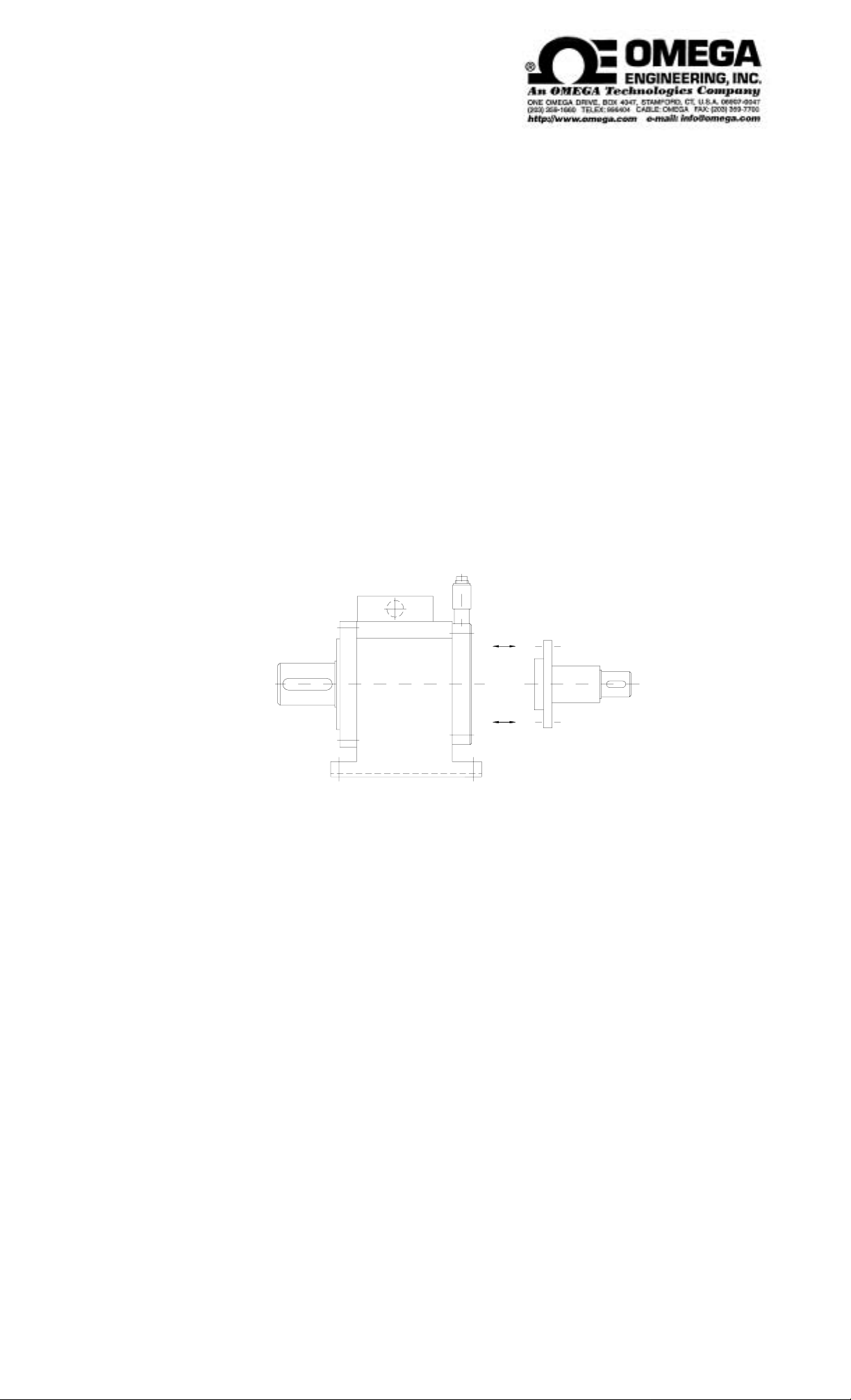
3.1 Mechanical design
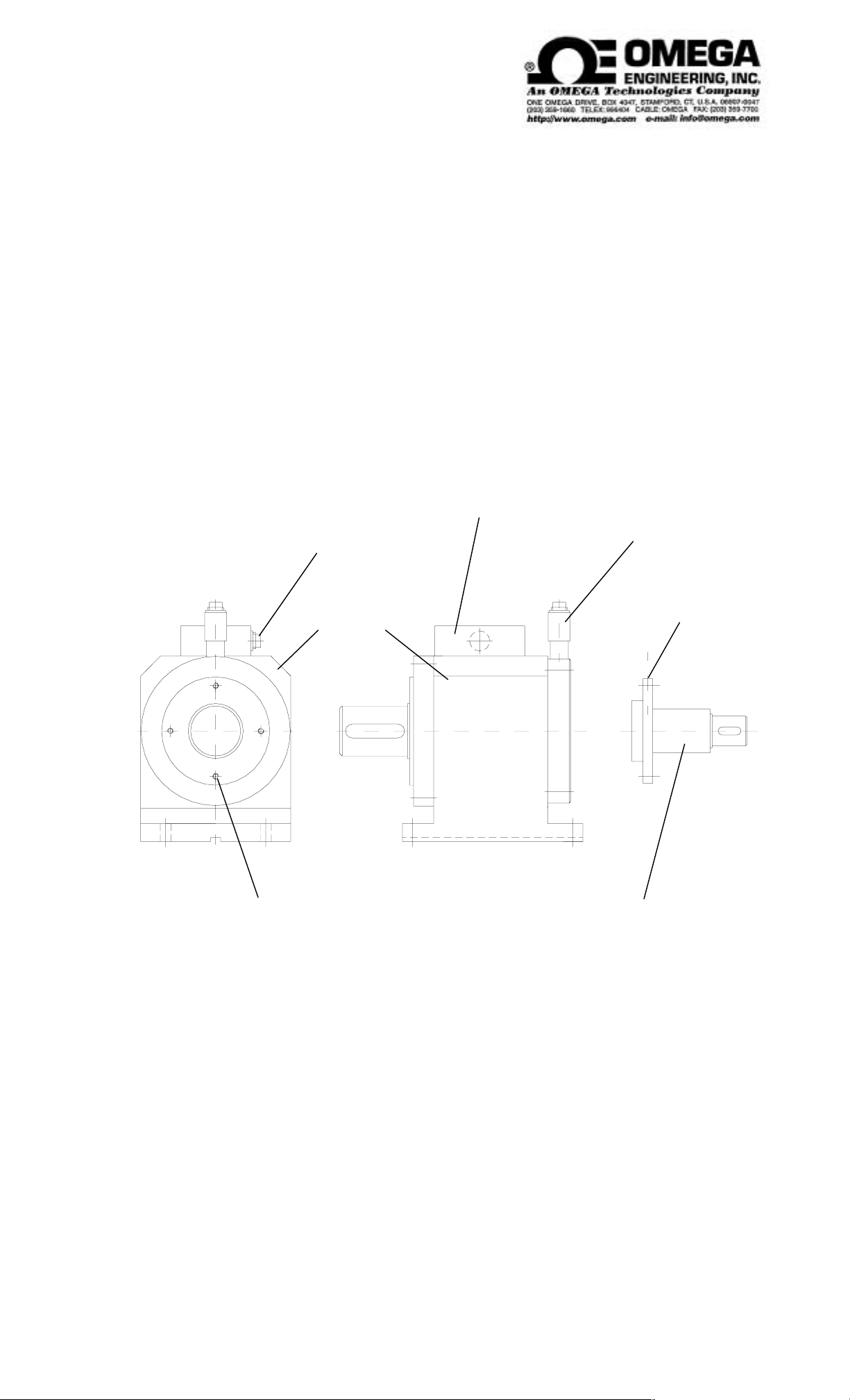
The transducer consists of a base body with a foot and replaceable measuring elements. These are
connected to the base body by means of 4 screws. The torque is transmitted via two claws. In the
center of these claws, plug contacts for transmitting the measured values are arranged. The measuring
element consists of a torque rod equipped with strain gauges. The measuring element flange holds a
calibration switch used for the gain adjustment required after a measuring element change.
(Please also refer to the illustration below.)
The base body houses the required electronics. One part of the electronics is located in the rotating
shaft, the other in the terminal box. The coils required to transmit the measured values from the rotating
to the stationary part are also housed in the base body.
cable connection
base body
fixing screws for
measuring element
terminal box
with electronics
speed sensor
(option)
calibration
switch
replaceable
measuring element
Page 4 / 16
Page 5
3.2 Electrical design
Brief description
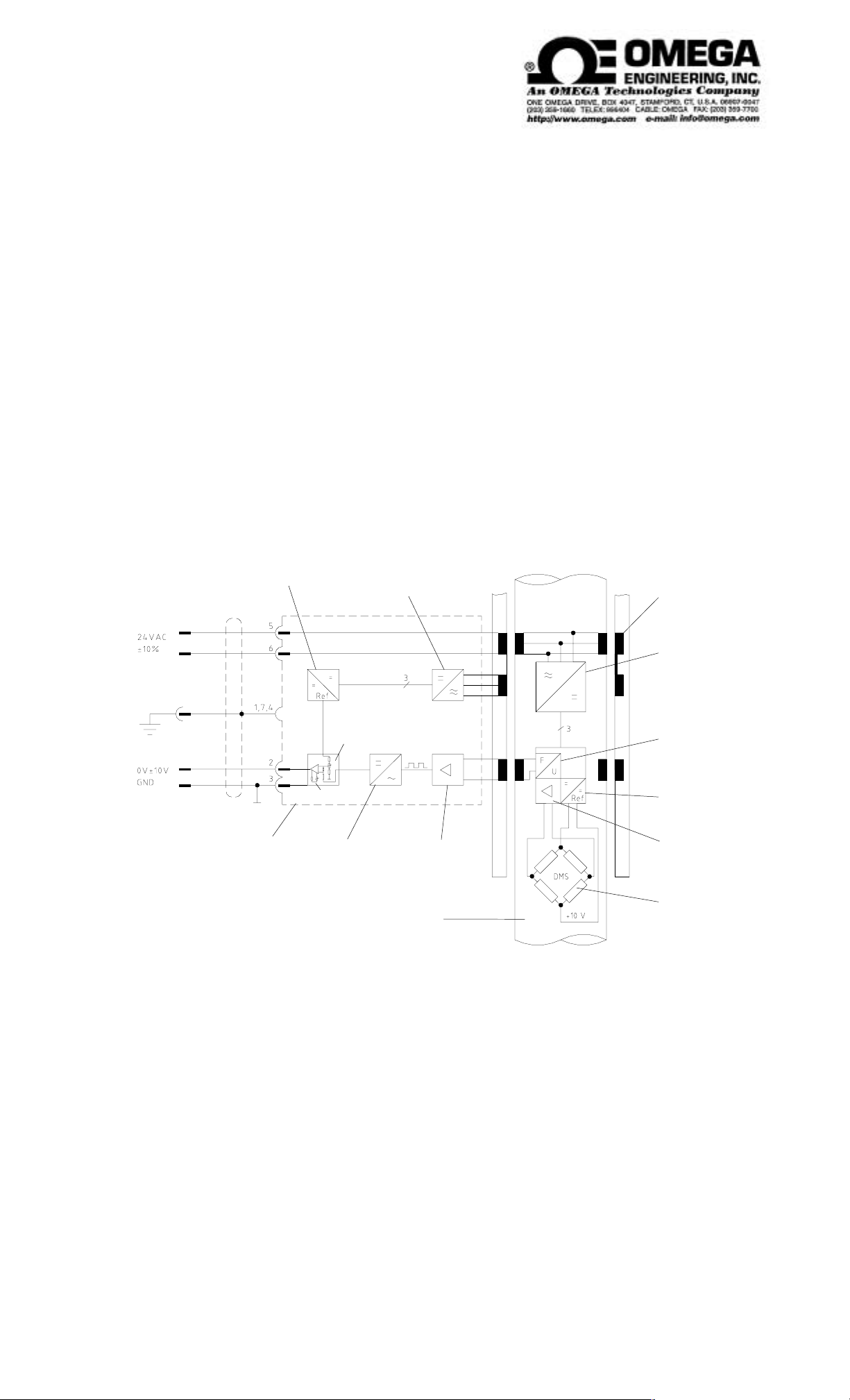
The figure below shows the functional principles used here for frequency-modulated signal
transmission.
The supply voltage for the electronics is 24 V AC. A rotary transformer is used to transmit the AC
excitation voltage. This voltage is rectified and stabilized.
The output signal of the strain gauge bridge is preamplified and fed to a voltage/frequency converter.
This converter gives a corresponding AC output voltage.
The output signal is transmitted by a second transformer to the nonrotating part of the transducer. The
transformers themselves are a pair of concentrically wound coils with one coil rotating within or beside
the stationary coil. The magnetic flux lines are produced by applying a time-varying voltage to one of
these coils. The transmitted frequency-modulated signal passes across a Schmitt trigger and a
frequency/voltage converter.
This voltage is applied to the input of a amplifier which gives an analog output of ± 10 V according to
the direction of rotation (10 V at nominal torque).
fine stabilisation
meas. cable
plug housing
rectification and
stabilisation
zero point
gain
frequency / voltage
converter
rotating
measuring
shaft
pulses
former
transducer
for supply voltage
rectification and
stabilisation
voltage / frequency
converter
fine stabilisation
pre-amplifier
strain gauge
bridge
Page 5 / 16
Page 6

3.2.1 Electrical design of speed measurement
Reflection light barrier for speed collection by optical scanning of a screened wheel.
+50mA 0V
light barrier
transducer
screened wheel
on shaft
external
A gallium-arsenide LED serves as transducer, which emits in the near infrared. The light reflected by
the screened wheel is transformed into an electrical signal by a photo transistor.
For adequate counters please refer to data sheet no. 4301.
Page 6 / 16
Page 7

4. Electrical connection of the torque transducer
4.1 Power supply
FM torque systems require a supply voltage of::
24 V / 50 Hz ± 10%
The alternating voltage is fed at the 7-pole plug at pin 5 and 6.
Current transmission can reach max. 1 A
Recommended supply circuit
F1
T 0,5 A
L1
PE
N
transformer
220 V
50 Hz
EP 50
28V~
26V~
24V~
65
build-in plug, 7-poles
Page 7 / 16
Page 8

4.2 Connection assignment for torque transducer
Function Pin Description
Mass or shield 1 (Shield is connected to ground of excitation unit)
Torque output ± 10V 2 Potential free,
only for small differences in potential
Torque output 0V 3 Potential free,
only for small differences in potential
Mass or shield 4 (Shield is connected to ground of excitation unit)
Supply voltage 5 Nominal voltage 24 V AC
Supply voltage 6 Nominal voltage 24 V AC
Mass or shield 7 (Shield is connected to ground of excitation unit)
Installed connector: Binder series 680 type 09-0327-80-07 (7-poles) or equal in construction.
The connected impedance between pin 2 and 3 must be > 2 kW.
Cable legths:
At cable lengths over 10 m the load-depending voltage decrease must be considered.
Page 8 / 16
Page 9

4.3 Connection assignment for the optional speed pick-up
Function Pin Description
0V 1 Signal receiver
12V to 24V DC at 2kW
0V 3 Supply for emitter
50 mA 4 Supply current for emitter
Installed connector: Binder series 680 type 09-0311-80-04 (4-poles) or equal in construction.
2 Output (receiver + supply)
Connection of the optional speed pick-up to external devices:
0 - 10 V DC - output
0 - 20 mA - output
BCD - output
Speed pick-up
(acc. to
data sheet 3101)
Counter
(acc. to
data sheet 4301)
4.4 Installing the measuring cable
· Do not lay parallel to heavy-current leads or control wires
· Not in the vicinity of heavy electromagnetical fields such as transformers, welding devices, relay,
motors, etc.
· If this cannot be avoided, however, lay measuring cable in grounded steel armor pipe.
· Lay cable in a loop at the transducer, in order to prevent cable damages caused by vibrations.
Page 9 / 16
Page 10

5. Mechanical assembly of the torque transducer
a) Couplings
· Well proved couplings are the rotary stiff ones produced by Thyssen (Rigiflex), e.g. form 14,
produced by Rexnord (Thomas) type 960, Thomas type 904 or similar couplings.
Please choose couplings with perfect centering.
· For higher speeds, it is important to use short-built (kurzbauende) couplings as presented in the
picture. This is because like that, a larger bending self-resonance can be obtained.
· Please refer to our data sheets 8301 or 8302.
Short-built full coupling:
Torque transducer à
Page 10 / 16
Page 11

b) Assembly suggestion
cable connector
torque
bearing bearing
drive, e.g. motor base body
cable connector
speed (optional)
full couplingfull coupling
replaceable
measuring element
e.g. brake
c) Assembly
· Attention: At the assembly make sure that no excessive torques and bending forces occur
between both shaft ends and between shaft and basic setup of the torque transducer.
· The measuring element is attached to the basic setup. Due to a rotation protection (pin in the basic
setup), the element can be attached in one direction only.
· Secure measuring element axially with screws. Torque is transmitted via the assembled feather
keys.
· The shaft string must be precisely adjusted. Please adhere to the coupling producers’ instructions.
· Fasten basic setup with screws and secure bolts.
Page 11 / 16
Page 12

d) Mounting the ccoupling at the drive end
full coupling drive end measuring end
ß support at the shaft
base body
l do not knock or beat
l just press
The shaft should be supported without measuring element, so that the ball bearings are not damaged in
their basic construction durin g the as s embly.
e) Mounting the coupling on the measuring element
Here as well, no excessive forces must have an effect on bearing and measuring element. The boss
should be able to slide on the shaft end without force. In case of narrow tolerances, the boss may be
mounted in warmed condition.
f) In addition, please note:
· The unit should be secured with a burst protection corresponding to the machine protection law
according to ISO 7475.
· We recommend to calculate the shaft string relevant to the torsion- and bending critical speeds.
Please avoid such speeds during operation. For a safe operation of the unit, we recommend, to
remain approx. 30% below and/or above the critical speeds.
· After the installation, depending on speed, a heave (Betriebswuchtung) of the unit according to VDI
2060 should be carried out.
· Machine vibrations should be tested according to VDI 2056.
References:
Dubbel pocket book for technical engineering, edited by Springer
F. Holzweißig, H. Dreßig, textbook of machine dynamics, Springer
VDI 2056 evaluation standards for mechanical vibrations of machines .
Page 12 / 16
Page 13

6. Calibration of the transducer
only possible with calibration device
The torque transducers are calibrated before delivery. If, however, a new adjustment of the torque
transducer is necessary, proceed as follows:
6.1 Zero point adjustment
Remove the cover near the socket at the connection box of the stator. Two markings are located on the
plug housing (figure 3). At the trim-potentiometer labeled with “0” adjust the zero point at completely
unloaded transducer which should be warm from operation. At the output exactly 0 V must be assigned,
see figure 5 (display e.g. via digital multi-meter). If the control range of the 0-point is not sufficient,
please assume that the torque transducer was overloaded and there is a remaining deformation of the
torsion section.
6.2 Gain adjustment
(only proceed with the use of a ca libration device)
If the output voltage varies from the 10 V set point with rated-torque loaded shaft, the transducer must
be re-adjusted. With the gain potentiometer “V” (see illustration below) the output voltage of the
transducer is adjusted to exactly 10 V.
After that, check the zero point at unloaded shaft.
Attention
An uncontrolled turning at the gain potentiometer results in destruction of the calibration. Electrical
calibration is possible.
cable connector
service connector, 7-poles
0=Zero point
V=Gain
Annotation:
At the feed unit for FM-measuring shafts of type VA 3200 there is another adjustment possibility for zero
point and gain.
For a zero point and/or gain correction without available calibration device, we recommend to execute
the necessary corrections at the corresponding potentiometers, the adjustments at the transducer
remaining unchanged.
Page 13 / 16
Page 14

6.3 Mechanical calibration
This operation requires a calibration device with lever arm and weights for generation of torque.
Steps in the calibration process:
a) load transducer with nominal torque and unload.
b) exactly adjust the zero point
c) load transducer with known torque
d) adjust display to the corresponding torque
Recording of a calibration curve:
a) calibrate transducer as shown above.
b) load transducer in 1/10 steps until complete nominal torque. After that unload in the same manner.
Between the single 1/10 steps wait at least 30 seconds until measured value is stable, then register
displayed value.
6.3.1 Construction of a simple calibration device
lever arm
lever arm
bearing
shiftable half couplings
torque
transducer
counter
holding device
lever arm
(double) bearing
for lever arm
weight
(calibrated)
Page 14 / 16
Page 15

6.3.2 Example for the calculation of lever arm length
Mt
L =
m • g
Mt = torque
L = required lever arm length
m = required mass
g = 9,80665 m/sec² = normal case acceleration
(g dependent on location)
EXAMPLE: m = 1 kg; Mt = 10 Nm
Mt
L
m
10 Nm sec²
=> L = = 1,0197 m
1 kg • 9,80665 m
6.4 Electrical calibration
Calibrate when?
Kalibrierschalter
· after change of exchange element
· as a control
replaceable
measuring element
Calibration process
· Allow 10 minute warm-up for the transducer
· Transducer must be torque-free, if possible remove coupling on the measuring end
· Adjust zero point
· Press calibration switch and hold it.
· Adjust output voltage to exactly 10V by turning at the gain.
· After that release calibration switch and control zero point.
· If necessary, repeat the procedure.
Annotation: Zero point and gain may be adjusted at the feed unit VA 3200.
Page 15 / 16
Page 16

7. Maintenance
· Transducers of the series FM are almost maintenance-free
· Durability of the bearings in nominal temperature range is approx. 20 000 hrs.
· Durability of the bearings in work ing tem peratur e range is approx . 10 000 hrs.
· Renewal of the bearings can only be done at the factory.
· Precision applications: Re-calibrate the transducer on a yearly basis.
(calibration at the factory or with adequate calibration device)
· Control every month, if position of the cable plug is stable.
· Control every month if the cable is damaged.
8. Repairing of the measuring shaft
· Shaft sluggish:
defective bearing
a) due to torsion or bending vibrations
b) due to excessive axial or radial loads
c) due to old or soiled bearing
d) shaft is concealed due to excessive cross-load
Remedy:
Send it to the factory.
· Zero point shift less than about 2 %
Re-adjust the zero point.
· Zero point shift between approx. 2 % and approx. 5%: Transducer was overloaded.
Zero point can once be re-adjusted at the amplifier.
· Zero point shift over approx. 5% or several times between 2% and 5%
Send transducer to the factory for examination.
· Transducer has hysteresis between cw and ccw.
Transducer was overloaded.
New torsion shaft required. Please send the transducer back to the factory.
Page 16 / 16
 Loading...