

Page 1
Operating Instructions
Rotary Torque Transducer
Model TQ 503 (with standard square connections)
Model TQ 503 X (including rangle measurement)
Model TQ 503 R (with shaft ends)
Operating Instructions no. 1333
Model TQ 503
Operating Instructions no. 1333
Page 1 / 17
Page 2

Contents
1. Contents
2. Application and key features
3. Description
3.1 Mechanical design
3.2 Electrical design
3.3 Rotation angle measuring system (only version X)
4. Electrical connections
4.1 Description of interfaces
4.2 Installing the signal lead
5. Using the torquemeter
5.1 Version Q, X
5.2 Version R
6. Static calibration
6.1 Making a simple calibration device
6.2 Calculation example for lever arm length
7. Maintenance
8. Repairs
See datasheet for technical details.
Operating Instructions no. 1333
Page 2 / 17
Page 3

2. Application and key features
· Torquemeter with strain gauges
· Signal transfer by sliprings
· Measurement of constant and variable torque
· Measurement of torque from the rotating shaft
· Integrated system for rotation angle measurement (only version X)
· Suitable for laboratory use and quality control
· Ideal for use with power tools
· Primarily suitable for low speed ranges
· Suitable for momentary measurement of torque (intermittent duty)
Operating Instructions no. 1333
Page 3 / 17
Page 4

3. Description
3.1 Mechanical design
Torquemeters type SD comprise a rotating shaft mounted on bearings inside a housing. The shaft has a
necked section - called the torsion zone - to which strain gauges are attached and connected in a full
bridge circuit. Sliprings and brushes provide the link between rotor and housing with two sliprings
carrying the electric power supply to the strain gauges on the rotating shaft. Two other sliprings serve to
transfer the measuring signals from the rotating shaft to the stationary housing. The full bridge circuit is
connected directly through the sliprings and brushes to the lead connector which is mounted on the
housing of the torquemeter.
In version X torquemeters an optical rotation angle measurement system is integrated. It consists of a
pulse disk on the rotating shaft with 360 light-dark stripes. Two light barriers are installed into the stator.
Inside the torquemeter there is a small electronics for processing of the angle pulses.
Square socket
(version Q / X)
or hexagon socket
(version H)
or shaft end with
feather key slots
(version R)
Shaft
Bearing
Brushes
Slip rings
Lead connector
Rotation angle
measuring system
(only version X / HA)
Housing
Square end
(version Q / X)
or hexagon end
(version H)
or shaft end with
feather key slots
(version R)
Bearing
Strain gauges
Torsion zone
Operating Instructions no. 1333
Page 4 / 17
Page 5
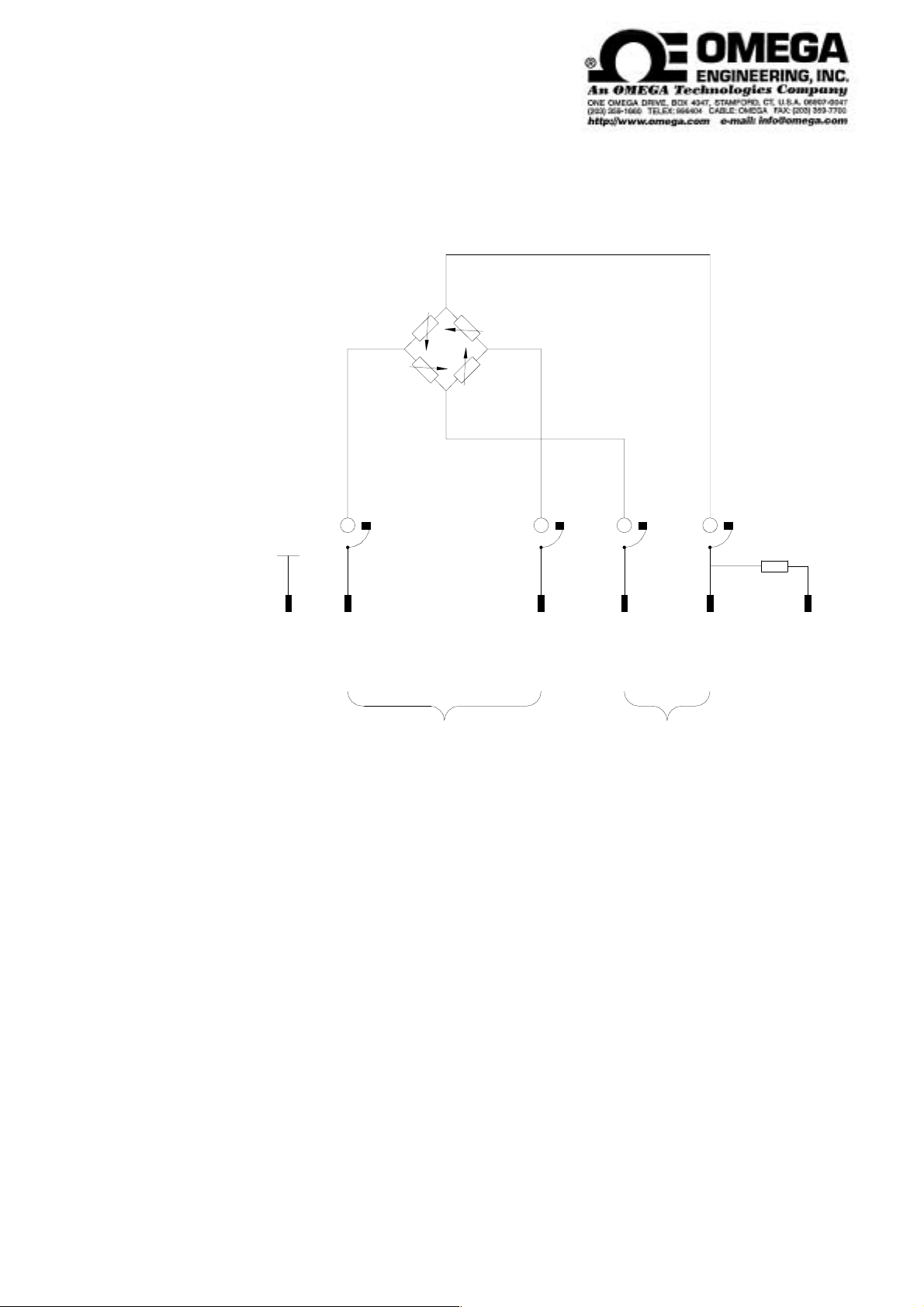
3.2 Electrical design
Shield
R4R3
R2 R1
S4S3S2S1
Version Q, R, H:
Version QA:
Version H
(special design):
U
B
R1 ... R4 = Gauges for measuring mechanical strain
S1 ... S4 = Sliprings with brushes
Signal leads
654213
KDCBAM
FDCBAE
Calibration
voltage
Operating Instructions no. 1333
Page 5 / 17
Page 6
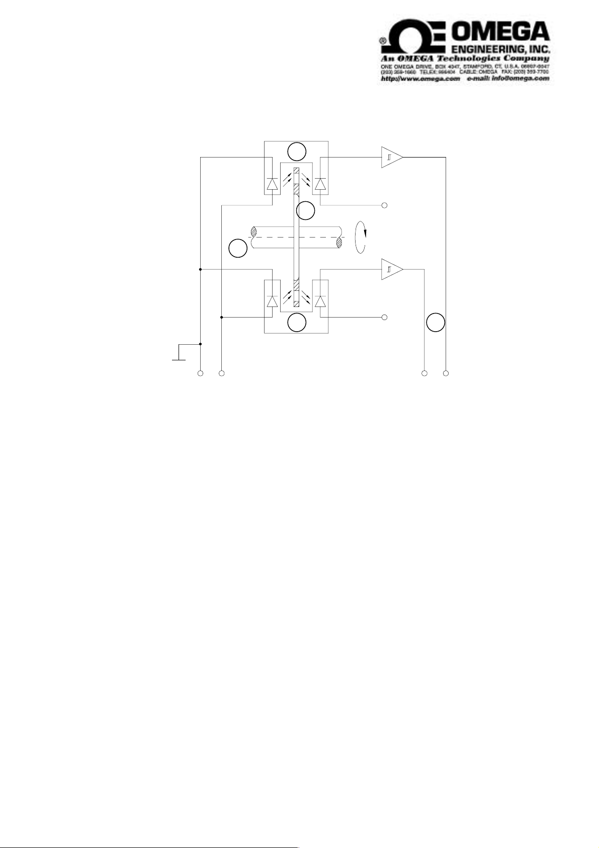
3.3 Rotation angle measuring system (only version X)
3
2
1
3
+5V0V
FEHG
Diagram showing the design of the rotation angle measuring system
1 rotating shaft
2 pulse disk
3 forked light barrier with LED and photo diode
0 V
4
4 operation amplifier
Features
- 360 light-dark stripes on the pulse disk
- two forked light barriers shifted by phase angle 90°
- pulse number proportional to the rotation angle
Operating Instructions no. 1333
Page 6 / 17
Page 7

Adjustment for angle-pulse output (only version X)
with drive on square socket
sense of rotation cw
Output Pin G
Output Pin H
Label M for
Measuring side.
Side with bearings
W
drive side
View W:
Size RSize Q/R
Sense of rotation
Operating Instructions no. 1333
Page 7 / 17
Page 8

4. Electrical connections
Lead connector
Shielded
lead
To power supply unit and display
Torquemeter (all versions)
Shielded lead of 0,25 mm² (version X: 0.14 mm²) cross section
Factory-calibrated with 5 m of lead. A change in length of 2.5 m will cause an error of
approximately 1 %
Operating Instructions no. 1333
Page 8 / 17
Page 9

4.1 Description of interfaces
E
ADF
Versions Q / R / H:
Function Pin Description Top view built-in plug
- Power supply 1 e.g. -6 V DC
+ Power supply 2 e.g. +6 V DC
Shield 3 not connected
+ Signal 4 2 mV/V approx. 350 W *)
- Signal 5 2 mV/V approx. 350 W *)
- Power supply 6 100% calibration
(Calibration voltage) causes 100% signal
Version X:
Function Pin Description Top view built-in plug
- Power supply A Strain gauge full bridge
+ Power supply B
+ Signal C
- Signal D
0 V E Rotation angle pulses
+ 5 V ± 10 % F
Pulse l, leading, TTL G
Pulse r, lagging, TTL H
0 V I
- Power supply K 100% calibration
(Calibration voltage) causes 100% signal
Shield M not connected
Version H (special design):
Function Pin Description Top view built-in plug
+ Power supply A e.g. +6 V DC
- Power supply B e.g. -6 V DC
- Signal C e.g. 2 mV/V approx. 350 W *)
+ Signal D e.g. 2 mV/V approx. 350 W *)
Shield E not connected
- Power supply F 100% calibration
(Calibration voltage) causes 100% signal
B
C
*) customized, see calibration certificate
Operating Instructions no. 1333
Page 9 / 17
Page 10

4.2 Installing the signal lead
Do not run the lead parallel to power cables or control circuits.
Do not place the lead close to equipment producing strong electromagnetic fields,
e.g. transformers, welders, contactors, electric motors, etc.
If such situations cannot be avoided, run the lead inside earthed steel conduit.
Make a loop in the lead when fixing it at the torquemeter so that it is not damaged by vibration.
Operating Instructions no. 1333
Page 10 / 17
Page 11

5. Using the torquemeter
5.1 Versions Q, X and H
Torquemeters of version Q and X have square connections for plug-in tools acc. to DIN 3121
Torquemeter of version H have hexagon connections acc. to DIN 3126, form E/F.
The torquemeters are plugged on to the drive spindle as shown below.
Application examples:
motor /
el. or pneum.
wrench
Lead
connector
Torquemeter
Type SD
Versions Q / X Version H
Lead
connector
socket spanner / bit
Operating Instructions no. 1333
Page 11 / 17
Page 12

5.2 Version R
The torquemeter is adapted to th measuring application by couplings.
For a free floating installation we recommend two torsioally rigid half couplings.
Application example:
Torquemeter
Motor
Test
specimen
Operating Instructions no. 1333
Page 12 / 17
Page 13

6. Static calibration
This procedure requires the use of a calibration device with a lever arm and weights for producing
specific values of torque.
The calibration procedure is as follows:
a) Apply the rated value of torque to the torquemeter and then remove it again.
b) Adjust the zero reading accurately.
c) Apply a known value of torque to the torquemeter.
d) Adjust the displayed reading to the corresponding value.
Plotting a calibration curve
a) Calibrate the torquemeter as described above.
b) Apply torque in 1/10 steps up to the full rated value and then remove it again in the same way.
A delay of at least 30 seconds must be allowed between the individual 1/10 steps so that each
reading can stabilize before it is recorded.
Operating Instructions no. 1333
Page 13 / 17
Page 14

6.1 Making a simple calibration device
Torquemeter
Lever armLever arm
KK
Lever arm
bearing
K = Loose half-couplings
Counter bearing Lever arm bearing
(duplex)
Weight
(calibrated)
Operating Instructions no. 1333
Page 14 / 17
Page 15

6.2 Calculation example for lever arm length
Mt
L=
m x g
Mt = Torque
L = Length of lever arm required
m = Mass required
g = 9.80665 m/s² (= standard gravity - varies with location)
Mt
Example: m= 1 kg
Mt = 10 Nm
10 Nm s
2
è L = = 1,0197 m
1 kg x 9,80665 m
m
L
Operating Instructions no. 1333
Page 15 / 17
Page 16

7. Maintenance
Gradual wear of the brushes and sliprings produces an electrically-conductive dust inside the
torquemeter which might cause an electrical short between the sliprings and cause instability of
the zero reading during rotation. Therefore, it is important to clean the torquemeter regularly.
The recommended cleaning cycle is approximately 106 revolutions
In order to clean the interior, loosen the 4 fixing screws and remove the cover plate
Use a soft linen cloth, a fine hair brush or oil-free compressed air to clean the dust from the
sliprings and the spaces between them
Carefully clean the brushes and the plastic part with the springs using a hair brush or oil-free
compressed air
Version X: Be careful when cleaning, do not scratch the pulse wheel.
Also clean the lead connector
Measure the brush thickness; it should be more than 0.5 mm. New brushes can only be fitted at
the factory.
Replace the cover plate carefully and re-tighten the fixing screws
Check the torquemeter:
Zero reading stable during rotation.
Produce a torque by twisting the meter by hand and note the reading.
If the torquemeter is used for precision work it should be recalibrated every year (either at the
factory or by means of a suitable calibration device)
Operating Instructions no. 1333
Page 16 / 17
Page 17

8. Repairs
Fault Cause Remedy
Shaft stiff to turn Bearing defect due
to:
a) Torsional or
flexural vibration
b) High axial or
radial loads
c) Worn bearings
d) Bent shaft
Zero shift less than
2%
Zero shift between
approx. 2 and 5% of
full scale
Hysteresis between
clockwise and
anticlockwise torque
Torsional vibration
Torsional shock
Torquemeter has been
overloaded
Torsional vibration
Torsional shock
Torquemeter overloaded by high
alternating loads or
torsional vibration
Return to factory
The zero reading can
be readjusted at the
display
The zero reading can
be readjusted once at
the display
Return to factory
Zero unstable during
rotation
Angle pulses roll out
(only version X)
Sliprings and/or
brushes dirty
Pulse disk and optical sensor
are soiled by coal dust
Operating Instructions no. 1333
Open and clean the
torquemeter
(see section 7)
Clean carefully
Page 17 / 17
 Loading...