

Page 1
User’s Guide
®
Shop online at
omega.com
e-mail: info@omega.com
For latest product manuals:
omegamanual.info
MADE IN UNITED KINGDOM
®
OS-MINI SERIES
Miniature Non-Contact Infrared
Temperature Sensors With
Separate Electronics Modules
Page 2

OMEGAnet®On-Line Service Internet e-mail
omega.com info@omega.com
Servicing North America:
U.S.A.: OMEGA Engineering, Inc.
ISO 9001 Certified
One Omega Drive, P.O. Box 4047
Stamford, CT 06907-0047 USA
Toll-Free: 1-800-826-6342 TEL: (203) 359-1660
FAX: (203) 359-7700 e-mail: info@omega.com
Canada: 976 Bergar, Laval (Quebec), H7L 5A1 Canada
Toll-Free: 1-800-826-6342 TEL: (514) 856-6928
FAX: (514) 856-6886 e-mail: info@omega.ca
For immediate technical or application assistance:
U.S.A. and Sales Service: 1-800-826-6342/1-800-TC-OMEGA
Canada: Customer Service: 1-800-622-2378 1-800-622-BEST
Engineering Service: 1-800-872-9436/1-800-USA-WHEN
®
®
Mexico/ TEL: 001 (203) 359-1660 FAX: 001 (203) 359-7700
Latin America e-mail: espanol@omega.com
Servicing Asia:
China: 1698 Yi Shan Road, Unit 102, Min Hang District
Shanghai, China 201103 P.R.C.
Hotline: 800 819 0559/400 619 0059 e-mail: info@cn.omega.com
Servicing Europe:
Benelux: Toll-Free: 0800 099 3344 TEL: +31 20 347 21 21
FAX: +31 20 643 46 43 e-mail: sales@omegaeng.nl
Czech Frystatska 184, 733 01 Karviná, Czech Republic
Republic: TEL: +420-59-6311899 FAX: +420-59-6311114
e-mail: info@omegashop.cz
France: Toll-Free: 0805 541 038 TEL: 01 57 32 48 17
FAX: 01 57 32 48 17 e-mail: esales@omega.fr
Germany/
Austria:
Daimlerstrasse 26, D-75392 Deckenpfronn, Germany
Toll Free: 0800 832 6342Tel:+ 49 (0) 7056 9398-0
FAX: +49 (0) 7056 9398-29 e-mail: info@omega.de
United OMEGA Engineering Ltd.
Kingdom: One Omega Drive
ISO 9001 Certified
River Bend Technology Centre, Northbank
Irlam, Manchester M44 5BD United Kingdom
Toll-Free: 0800-488-488 TEL: +44 (0) 161 777-6611
FAX: +44 (0) 161 777-6622 e-mail: sales@omega.co.uk
®
It is the policy of OMEGA to comply with all worldwide safety and EMC/EMI regulations that
apply. OMEGA is constantly pursuing certification of its products to the European New
Approach Directives. OMEGA will add the CE mark to every appropriate device upon
certification.
The information contained in this document is believed to be correct, but OMEGA
Engineering, Inc. accepts no liability for any errors it contains, and reserves the right to alter
specifications without notice.
WARNING: These products are not designed for use in, and should not be used for, human
applications.
Page 3

The OS-Mini Series is a range of miniature non-contact infrared temperature sensors
with separate electronics modules.
All models have an adjustable emissivity setting and are capable of measuring a wide
variety of target materials, including food, paper, textiles, plastics, leather, tobacco,
pharmaceuticals, chemicals, rubber, coal and asphalt.
The optional touch screen interface provides temperature indication, alarms, sensor
configuration and data logging to MicroSD Card. The optional high-temperature
sensing head may be used in ambient temperatures of up to 180°C without cooling.
The low-noise cable on high ambient temperature models is resistant to interference
from movement, so it is ideal for mounting on moving objects such as robot arms.
A choice of optics are available to measure small or large targets at short or long
distances, and there is a choice of 4-20 mA, RS485 Modbus and alarm relay outputs.
SPECIFICATION
GENERAL
Temperature Range See table of Model Numbers
Maximum Temperature Span (-CRT models) 1020°C
Minimum Temperature Span (-CRT models) 100°C
Output 4 to 20 mA or RS485 Modbus
Field of View See table of Model Numbers
Accuracy ± 1°C or 1%, whichever is greater
Repeatability ± 0.5°C or 0.5%, whichever is greater
Emissivity Setting Range 0.20
Emissivity Setting Method MA models: via two rotary switches in electronics
module
C4 models: via RS485
MA-R-D & CR-R-D models: via touch screen
Response Time, t
Spectral Range 8 to 14 µm
Supply Voltage 24 V DC ± 5%
Maximum Current Draw 100 mA
Maximum Loop Impedance -CB and -CRT models: 900 Ω (4 to 20 mA output)
Alarm Relays (-CRT models) 2 x Single Pole Changeover alarm relays rated
24 V DC, 1 A, isolated 500 V DC
240 ms (90% response)
90
to 1.00
MECHANICAL
Sensing head Electronics Module
Construction
Major Dimensions
Mounting
Cable Length (sensing head to electronics module) 1 m (standard), up to 30 m (optional)
Weight with 1 m Cable 390 g (approx)
Cable Connections Removable screw terminal blocks (see
Output Cable Gland Suitable for cable diameters 3.0 to 6.5 mm
2
›
Stainless Steel 316 Die-cast Aluminium
Ø18 x 45 mm 98(w) x 64(h) x 36(d) mm
M16 x 1 mm thread Two M4 screws for wall mounting (see
diagram)
Connections). Conductor size: 28 AWG to
18 AWG
Page 4

ENVIRONMENTAL
Sensing Head Electronics Module
(without touch
Environmental Rating
Ambient Temperature
Range
Relative Humidity
CE Marked
RoHS Compliant
ELECTROMAGNETIC COMPATIBILITY STANDARDS:
Class Standard Description
EMC Directive
- Immunity IEC 61000-4-2
- Emissions
IP65 (NEMA 4) IP65 (NEMA 4) –
See table of Model
Numbers
Maximum 95%
non-condensing
Yes Yes Yes
Yes Yes Yes
EN61326-1:2006 Electrical equipment for measurement,
IEC 61000-4-3 Electromagnetic Field Immunity
IEC 61000-4-4 Burst Immunity
IEC 61000-4-5 Surge Immunity
IEC 61000-4-6 Conducted RF Immunity
EN 55022A RF Emissions Class A
EN 55022B RF Emissions Class B
screen)
0°C to 60°C 0°C to 60°C
Maximum 95%
non-condensing
control and laboratory use – Industrial
Electrostatic Discharge Immunity
Electronics Module
(with touch screen)
Maximum 95%
non-condensing
MODEL NUMBERS
The following combinations of ambient temperature range, optics, measured temperature range,
output and interface are available on OS-MINI sensors:
Series
OS-MINI
Sensing Head
Operating
Temperature Range
MA
HA 201
Field of View
212
152
302
802
Measurement
Temperature
Range
LT
MT
HT
XT
CT
HT
XT
CT
Output and
Interface
MA
MA-R-D
C4
C4-R-D
MA
MA-R-D
C4
C4-R-D
›
3
Page 5

SENSING HEAD OPERATING TEMPERATURE RANGE
-MA 0°C to 60°C
-HA 0°C to 180°C
The high ambient temperature sensing head on -HA models is capable of withstanding
temperatures of up to 180°C without cooling. It is available with 20:1 optics.
There is no need to supply cooling air or water, and the miniature sensing head is much smaller than
bulky, cooled sensors.
FIELD OF VIEW
Distance: Sensor to object (inches)
0 4 8
(inches)
Spot Dia.
0.5
11.9
(mm)
Spot Dia.
0
2.4
61.9
100 200
Distance: Sensor to object (mm)
4.4
111.9
Distance: Sensor to object (inches)
0 19.7 39.4
(inches)
Spot Dia.
(mm)
Spot Dia.
0.5
11.9
0
1.8
45.2
500 1000
Distance: Sensor to object (mm)
212 152
Distance: Sensor to object (inches)
0 19.7 39.4
(inches)
Spot Dia.
0.5
11.9
(mm)
Spot Dia.
0 500 1000
1.1
28.6
Distance: Sensor to object (mm)
302
1.8
D:S 30:1
45.2
Distance: Sensor to object (inches)
0
(inches)
Spot Dia.
0.5
11.9
(mm)
0
Spot Dia.
Distance: Sensor to object (mm)
802
3.9
0.20
5.0
100
MEASUREMENT TEMPERATURE RANGE (°C)
-LT
-MT
-HT
-XT
-CT
-20
0 100
Fixed (e.g. -MT: 0°C @ 4 mA, 250°C @ 20 mA)
MA-R-D models: 4 to 20 mA output configurable within this range
C4-R-D models: Digital output, full temperature range
250 500 1000
Distance: Sensor to object (inches)
3.1
D:S 15:1D:S 2:1
78.6
0 19.7 39.4
(inches)
Spot Dia.
0.5
11.9
(mm)
Spot Dia.
0 500 1000
1.5
36.9
Distance: Sensor to object (mm)
2.5
D:S 20:1
61.9
201
7.9
0.49
12.5
200
Diameter of target
spot measured versus
distance from sensing
head at 90% energy
OUTPUT AND INTERFACE
MA 4 to 20 mA output, no touch screen
MA-R-D 4 to 20 mA output and two alarm relay outputs, with touch screen
C4 RS485 Modbus output, no touch screen
C4-R-D RS485 Modbus output and two alarm relay outputs, with touch screen
4
›
Page 6
EXAMPLE: OS-MINI 302-CT-C4-R-D
BRT
Series Sensing Head
Operating
Temperature
OS-MINI -MA 0°C to 60°C -302 30:1
Optics Temperature
Range
-CT
divergent
within the limits:
-20 to 1000 °C
Output and
Interface
C4-R-D
Modbus output and two
alarm relay outputs, with
touch screen
RS485
EMISSIVITY ADJUSTMENT (-CB MODELS)
The emissivity setting on OS-MINI with MA output models may be adjusted via two rotary
switches inside the electronics box. To adjust the emissivity setting:
Set the left switch to the first digit after the decimal point (0.1).
Set the right switch to the second digit after the decimal point (0.01).
To enter an emissivity setting of 1.00, set both switches to 0.
The minimum emissivity setting is 0.2. If a lower emissivity setting is selected, the sensor will default
to an emissivity setting of 0.95.
For example:
Left switch Right switch Emissivity setting
6 3 0.63
0 0 1.00
TOUCH SCREEN (MA-R-D and C4-R-D MODELS)
The optional backlit touch screen interface mounted in the lid of the electronics module provides a
large, bright display of the measured temperature, as well as options for full configuration of the
sensor. The graph view shows the history of the measured temperature.
In alarm conditions, the display changes colour to provide an immediate and obvious alarm
indication. Alarm modes and levels can be configured via the touch screen.
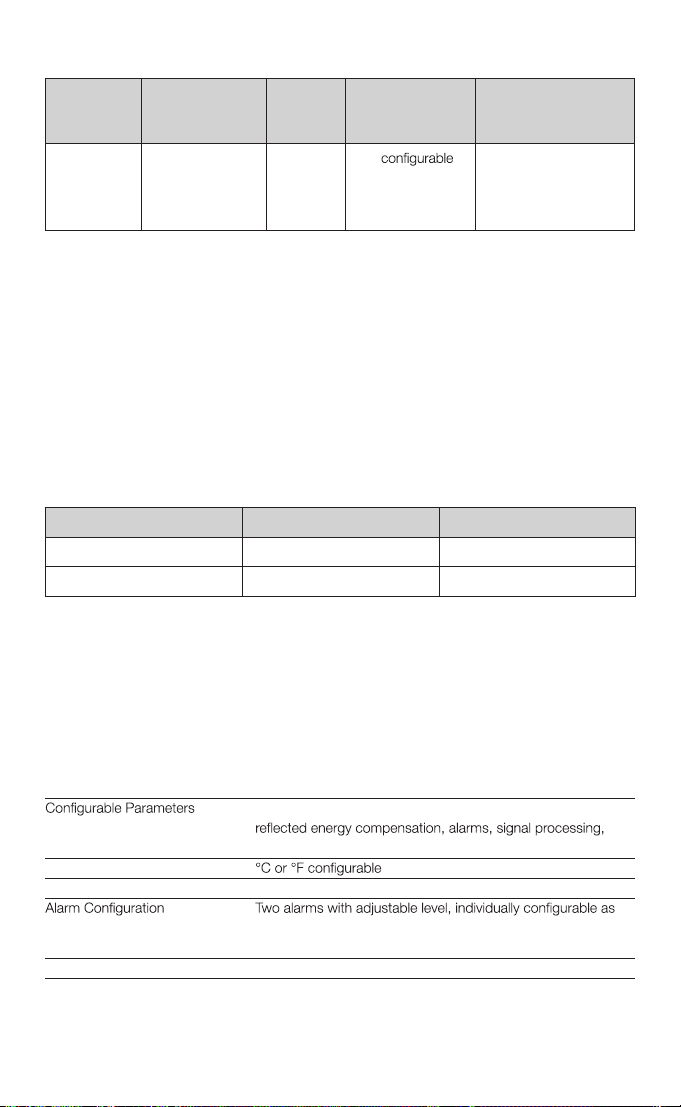
TOUCH SCREEN SPECIFICATIONS
Touch Screen Display Format 2.83” (72 mm) resistive touch TFT, 320 x 240 pixels, backlit
Temperature range, temperature units, emissivity setting,
Modbus address (-BRT models), date and time, data logging
Temperature Units
Temperature Resolution 0.1°
HI or LO. Alarm 2 can be set to target temperature or sensing
head internal temperature
Signal Processing Average, peak hold, valley hold, minimum, maximum
›
5
Page 7
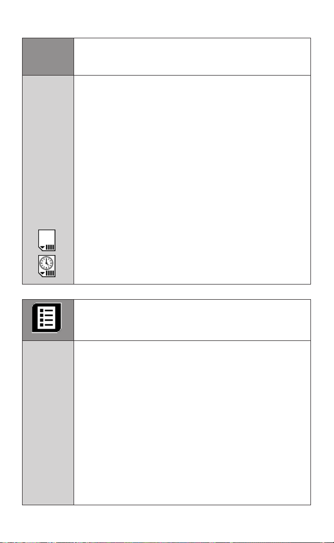
USER INTERFACE
Default View
Setting
Temperature
Units
Selecting
Displayed
Temperature
Temperature View
Displays a large indication of the measured temperature. The background
turns bright red when an alarm is activated.
Press “°C” to switch to °F and vice versa. The units are changed throughout
the interface.
Press the temperature display to select which reading is shown:
Filtered Temp
The measured temperature, with averaging and hold processing. This
temperature is output by the sensor on the 4 to 20 mA output (-CB and -CRT
models).
Average Temp
The measured temperature with averaging but without hold processing.
Unltered Temp
The unprocessed measured temperature.
MicroSD Card status.
This icon is displayed when an SD card is inserted, and ashes when data
logging is in progress.
This icon is displayed when scheduled data logging is enabled and has yet
to begin.
List View
Displays a list of the measured temperatures, alarm state and data logging
state.
Filtered Temp: The measured temperature, with averaging and hold
processing.
Unltered Temp: The unprocessed measured temperature.
Average Temp: The Unltered Temperature averaged over the period
specied in “Output Processing”.
Maximum Temp: The highest temperature measured during the hold period,
with averaging.
Minimum Temp: The lowest temperature measured during the hold period,
with averaging.
Sensor Temp: The internal temperature of the sensing head.
Reected Temp: The reected energy compensation temperature, as
specied in “Emissivity and Compensation”.
6
›
Page 8

Lock/Unlock
Prevents settings being changed via a four-digit numerical code.
Change Password
Enter, conrm and save a new four-digit code.
Start/Stop Logging
Manually begins or ends data logging (requires MicroSD Card, available
separately).
If Scheduled Start is enabled in Settings > Data Logging, then logging cannot
be started manually.
To manually start logging, you must rst disable Scheduled Start.
Graph
Displays the recent history of the Filtered Temperature and the Sensor
Temperature. To scroll backwards and forwards in time, touch the graph and
drag it. The graph stores the most recent 24 hours of temperature data.
Reset Graph
Clears and restarts the graph.
Real-Time Scrolling View
Returns the graph to the real-time scrolling view, showing the most recent
measurements.
Acknowledge Alarms
Switches the relay outputs for triggered alarms to their normal, untriggered
state. The background of the Temperature View, List View and Graph View
will stay red, and the alarms will not be triggered again, until the alarms are
reset (see “Alarms” below). Alarms can be acknowledged when the display
is locked.
Settings
Access the conguration parameters. Press Apply to save the settings,
or Exit to leave the screen without saving.
›
7
Page 9

SETTINGS
Date & Time
Change the date and time for data logging purposes. The clock is reset when
the power is cycled unless a battery is tted.
Output Processing
Averaging
Period
Hold Mode
Hold Period
Sample
Period
Number of
Samples
Set the time, in seconds, over which the measured temperature is averaged.
Note: averaging prevents the sensor from following rapid temperature
changes. Minimum: 0 (no averaging). Maximum: 60.
Peak
The sensor holds the maximum temperature steady for the Hold Period.
After this, the sensor responds normally. If the sensor detects a higher
temperature, it holds this temperature steady for the Hold Period.
Valley
Similar to Peak Hold mode except that the sensor outputs the minimum
detected temperature steady for the Hold Period.
Off
Disables hold processing.
Set the time, in seconds, for the sensor to hold the temperature as above.
Minimum: 0 (no hold processing). Maximum: 1200.
Data Logging
The time, in seconds, between samples. Minimum: 1. Maximum: 86,400
(1 day).
The number of samples to collect before logging stops. Minimum: 0
(continuous logging). Maximum: 86,400 (1 day of data if Sample Period = 1
second).
8
›
Enable
Scheduled
Start
Date and
Time
The sensor begins logging at the Date and Time specied. Logging can also
be started and stopped manually.
The date and time for scheduled logging to start.
Page 10

SETTINGS (continued)
Emissivity and Compensation
Emissivity
Setting
Enable
Energy
Compensation
Temperature
Temperature
at 4 mA
Temperature
at 20 mA
Please note
Enter the emissivity of the target. Target emissivity can be determined
experimentally, or estimated using an emissivity table. For more information,
contact Calex. Minimum: 0.2. Maximum: 1.0.
colder objects.
Compensation. Minimum: -20°C. Maximum: 1000°C.
4 to 20 mA Output (MA-R-D models)
Set the temperature range limits for the 4 to 20 mA output.
The lower temperature range limit. Minimum: -20°C. Maximum: 900°C.
The upper temperature range limit. Minimum: 80°C. Maximum: 1000°C.
The difference between the temperatures at 4 mA and at 20 mA must be at
least 100°C. The temperature at 20 mA must be greater than the temperature
at 4 mA.
Modbus Address (C4-R-D models)
Modbus
Address
The current Modbus address of the sensor is displayed. Enter a new address,
then press Apply to save it to the sensor. Cycle the power to use the new
address.
Minimum: 1. Maximum: 247.
Alarms
alarm logging settings.
Manually Reset Alarms
If an alarm has been triggered, allows both alarms to be triggered again.
Alarms will not be triggered again until they are reset, either automatically or
manually.
›
9
Page 11

SETTINGS > ALARMS
Alarm 1 and Alarm 2
Alarm Set
Point
Hysteresis
Filtered
Temperature
or Sensor
Temperature
(Alarm 2 only)
Alarm Type
Reset
The temperature at which the alarm is triggered. Minimum: -20°C. Maximum:
1000°C.
The temperature difference between the Alarm Set Point and the reset
temperature. Hysteresis is only used when Automatic Reset is enabled.
Please see the diagrams below for more information
Minimum: 0°C (hysteresis disabled). Maximum: 1000°C.
Select the temperature monitored by Alarm 2.
High
The alarm is triggered when the temperature rises above the Alarm Set Point.
Low
The alarm is triggered when the temperature drops below the Alarm Set
Point.
Off
The alarm is disabled.
Automatic
The alarm is acknowledged and reset automatically when the temperature
reaches the reset temperature (see Hysteresis). It can also be acknowledged
or reset manually.
Manual
The alarm is acknowledged by pressing Acknowledge on the
Temperature View or List View, and reset by pressing Reset on the
Alarms screen.
Alarm Logging
Alarm events can be logged to the MicroSD Card. Alarm log les and settings
are independent from Data Logging.
Log Trigger
Time
Log Data
While
Triggered
Log
Acknowledge
Time
Log Reset
Time
10
›
The time that an alarm is triggered will be logged.
Data logging will start when an alarm is triggered. 1 sample is logged per
second. Logging stops when both alarms are reset.
The time that the alarm is acknowledged will be logged.
The time that the alarm is reset will be logged.
Page 12

ALARM OPERATION WITH HYSTERESIS & AUTOMATIC RESET
Alarm triggered Alarm reset
Alarm Set Point
Hysteresis
Temperature
Time
Alarm triggered Alarm reset
Alarm Set Point
Hysteresis
Temperature
Time
High Alarm with Automatic Reset
Low Alarm with Automatic Reset
DATA LOGGING (MA-R-D and C4-R-D MODELS)
The OS-Mini can be used as a standalone data logger.
OS-MINI models MA-R-D and C4-R-D include a MicroSD card slot for data logging, which can
be
of samples to be taken and schedule the data logging to start at a certain time.
With a 2 GB card, the user can store 28.4 million readings, which provides almost 1 year’s worth
of data at the fastest possible sample rate of 1 per second.
Data is stored on the MicroSD card in .csv format and can be viewed and edited easily using
spreadsheet software.
A MicroSD card with SD card adapter is available as an optional accessory.
The MicroSD card slot and battery holder are located on the touch screen circuit board in the lid
of the OS-MINI. Readings are time and date stamped using the sensor’s internal clock. The clock
DATA LOGGING SPECIFICATIONS
Data Logging Interval 1 to 86,400 seconds (1 day)
MicroSD Card Max. capacity: 2 GB (not included)
Internal Clock Battery 1 x BR 1225 3V (not included)
Variables Logged Target temperature, sensing head temperature, electronics module temperature,
File format .csv
Sample period, number of samples, scheduled start date and time
Modbus address range 1 to 247
USING THE PYROMINI AS A DATA LOGGER
1. Insert a MicroSD card into the holder on the circuit board inside the lid of the OS-MINI electronics module.
2. To retain the date and time when the OS-MINI is switched off, fit a battery to the holder on the
circuit board inside the lid.
3. Replace the lid and connect the sensor power supply.
4. To set the number of samples to be logged, the time period between samples, and, if required,
to schedule data logging to automatically start, press to access the Settings menu, then
press to access the Data Logging options.
5. To save data logging settings, press
6. To manually start data logging, press on the Temperature View or List View.
7. While logging is in progress, the logging icon flashes on the Temperature Vi
8. To stop data logging, press .
9. To transfer data to a computer, remove the MicroSD Card from the sensor, insert the card into
the SD Card adapter (supplied with MicroSD Card, accessory model MSD) and insert the
adapter into an SD Card reader.
Note: MicroSDHC Cards are not compatible with the PyroMini.
ew and
List View.
11
›
Page 13

Thread M16 x 1 mm
Standard length:
18
98
48
18
64
36
20
36
86
1000 45
13
12
ø 18.6
Air Purge Collar
Sensing Head
4
18
ø 40
ø 29
25
1/8" BSP
air fitting
Removable spigot fitted to
type APSN for use with
-151, -201, -301 and -CF
models. Not fitted to type
APSW for -21 models.
Mounting Nut
(included)
ø 18
50
Electronics Module
Touch screen
(optional)
72 mm (2.83")
Cable glands:
14 mm AF
Mounting
holes: use M4
CSK screws
(supplied)
INSTALLATION OF MICROSD CARD AND BATTERY
MicroSD Card
Battery
(use 1 x BR 1225 3V)
DATA LOG FILES
Data is saved to the MicroSD Card in .csv format. This file format can be opened or imported by
spreadsheet software such as Microsoft Excel.
A new folder is created on the MicroSD Card for each day that data is logged.
A new log file is created every time logging is started. The start time is used as the file name.
DIMENSIONS
12
›
Page 14

12
45
50 50
40
9
15
25 25
60° Rotation 60° Rotation
60° Rotation
9
48
Fixed Mounting Bracket (FBS) Adjustable Mounting Bracket (ABS)
2 x Mounting Holes M4 Clearanc 2e x Mounting Holes M4 Clearance
9
2424
Ø16
ACCESSORIES
A range of accessories to suit different applications and industrial environments is available. These
may be ordered at any time and added on-site. The following accessories are available from Calex:
Fixed mounting bracket (see above for dimensions): Allows rotational adjustment in one
dimension. Model number: FBS.
Adjustable mounting bracket (see above for dimensions): Allows rotational adjustment in two
dimensions. Model number: ABS.
Air purge collar (see above for dimensions): The air purge collar is used to keep dust, fumes,
moisture, and other contaminants away from the lens. It must be screwed fully onto the
sensing head. Air flows into the 1/8” BSP fitting and out of the front aperture. Air flow should
be 5 to 15 l/min. Clean or ‘instrument’ air is recommended. Model APSW is for use with
sensors with 2:1 optics. Model APSN is for use with all other PyroMini models.
Laser sighting tool: When fitted to the sensor during installation or re-alignment, the laser
sighting tool pinpoints the centre of the measured spot. Model number: LSTS.
Protective plastic window with stainless steel holder: When screwed over the lens of the
sensor, this provides extra
mechanical protection for
the germanium lens and helps retain
fragments of the lens in case of damage. The emissivity setting of the sensor should be
adjusted to compensate for the presence of the window. This accessory is suitable for use in
ambient temperatures of 0 to 100°C. For more information, please contact Calex. Model
number: PWS
MicroSD Card: Stores logged data. For use with MA-R-D and C4-R-D models. Includes SD
Card adapter. Model number: MSD.
OPTIONS
The following options are available. Options are factory installed and must be ordered with the
sensor.
Extended Cable (30 m maximum total cable length): 1 m cable is supplied with each sensor
as standard. Extra cable can be added to this in increments of 1 m.
13
›
Page 15

INSTALLATION
Sensor
BEST
GOOD
INCORREC
Background
Target greater
than spot size
Target equal to
spot size
Target smaller
than spot size
The installation process consists of the following stages:
Preparation Mechanical installation Electrical installation
Please read the following sections thoroughly before proceeding with the installation.
PREPARATION
Ensure that the sensor is positioned so that it is focused on the target only.
T
DISTANCE AND SPOT SIZE
The size of the area (spot size) to be measured determines the distance between the sensor and
the target. The spot size must not be larger than the target. The sensor should be mounted so
that the measured spot size is smaller than the target.
AMBIENT TEMPERATURE
The OS-MINI is available with a choice of two miniature sensing heads, for use in low or high
ambient temperatures:
-MA models: The sensing head is designed to operate in ambient temperatures from 0°C to 60°C.
-HA models: The sensing head is designed to operate in ambient temperatures from 0°C to
180°C. No cooling is required, which saves the energy and cost of supplying air or water to
cool the sensor.
Avoid thermal shock. Allow 20 minutes for the unit to adjust to large changes in ambient
temperature.
ATMOSPHERIC QUALITY
Smoke, fumes, dust or steam can contaminate the lens and cause errors in temperature
measurement. In these types of environment the air purge collar should be used to help keep the
lens clean.
INTERFERENCE FROM MOVEMENT
The low-noise sensing head cable on -HA models is resistant to interference caused by movement.
The sensing head may be mounted on moving machinery such as robot arms without affecting the
accuracy of the measured temperature.
ELECTRICAL INTERFERENCE
The OS-MINI is tested to industrial standards for electromagnetic compatibility (EMC) as shown in
Specifications at the beginning of this manual.
14
›
Page 16

To minimise electromagnetic interference or ‘noise’, the sensor should be mounted away from
motors, generators and such like.
POWER SUPPLY
Be sure to use a 24 V DC (100 mA) power supply.
MECHANICAL INSTALLATION
All sensors come with a 1 m cable and a mounting nut as standard. Longer cables are available to
order. The sensor can be mounted on brackets or cut-outs of your own design, or you can use the
fixed or adjustable mounting bracket accessories.
Note: The sensor housing must be connected to earth at one point, either the housing of the
sensing head, the electronics module, or the output cable shield termination. To avoid ground
loops, please ensure the sensor is grounded at only one of these points.
ELECTRICAL INSTALLATION
CONNECTIONS
Sensing Head Cable
Colour Codes (all models):
TP+ Blue with white line
TP- White with blue line
MA and MA-R-D
TH+ Blue
GND White
C4 and C4-R-D
PWR+
PWR-
PWR+
PWR-
PWR-
OP-
OP+
OP-
OP+
15
›
Page 17

WIRING (ALL MODELS)
Check the distance between the sensing head and the electronics module, and between the
electronics module and the instrumentation. If necessary, the sensor can be ordered with a longer
cable between the sensing head and the electronics module.
The output cable from the electronics module should have an outer diameter between 3.0 and 6.5
mm, with conductors of size 28 to 18 AWG.
The terminal blocks in the electronics module may be removed from the circuit board for easy
wiring.
Do not disconnect the touch screen circuit board from the main circuit board while the sensor is on.
WIRING (C4 AND C4-R-D MODELS)
When connecting several sensors in a single Modbus network, all of the sensors should be
connected via a junction box to a single network bus cable, running from the furthest sensor to the
Modbus Master.
Up to 247 sensors may be connected to a single Modbus network. Each sensor must have a
unique Modbus address. PyroMini sensors are normally shipped with Modbus address 1. The
Modbus address may
To help prevent data reflections, please ensure the cable between each sensor and the main
network bus is as short as possible. The network bus should be terminated with a resistor of 120Ω
between the RS+ and RS- wires. The PWR- wire of the bus should be connected to the signal
ground of the Modbus Master.
be changed via the touch screen interface on -BRT models, or via Modbus.
MODBUS OVER SERIAL LINE (RS485)
Interface
Baud rate 9600
Format 8 data, No parity, 1 stop bit
Reply delay (ms) 20
Supported functions
Read register 0x03, 0x04
Write single register 0x06
Write multiple register 0x10
Mask write register 0x16
Read/write 0x17
The list below includes all available addresses:
R = Read
W = Write (single, multiple or read/write)
MW = Mask write
Address Length
0x00 1 MODBUS slave address R/W*
0x02
16
›
(words)
2
Description R/W/MW
Sensor identification register
Bits 0..19 - Serial number
Bits 20..23 - Sensor type (12 = PyroMini)
Bits 24..26 - Sensor field-of-view
For MA : 0 = 2:1, 1 = 15:1, 2 = 30:1
For HA : 0 = 20:1
Bits 28..32 - Reserved
R
Page 18

Address Length
0x06 1 Unfiltered object temperature R
0x08 1 Sensor temperature R
0x0A 1 Maximum temperature over hold period R
0x0C 1 Minimum temperature over hold period R
0x0E 1 Average temperature over hold period R
0x10 1 Filtered object temperature R
0x12 1 PCB temperature R
0x14
0x16 1 Reflected temperature R/W
0x18
0x1A
0x1C
0x1E 1 Temperature at 4 mA
0x20 1 Temperature at 20 mA
0x22 1 Alarm 1 setpoint
0x24 1 Alarm 1 hysteresis
0x26 1 Alarm 1 status register
(words)
1
1
1
1
Description R/W/MW
Emissivity (1 LSB = 0.0001)
Minimum 0.2000, Maximum 1.0000
Sensor status register
Bits 0..1 - Reserved
Bit 2 - Hold processing on (1)/off (0)
Bit 3 - Hold peaks (1)/valleys (0)
Bits 4..6 - Reserved
Bit 7 - Reflected energy compensation on (1)/
off (0)
Bits 8..15 - Reserved
Average period (1 LSB = 0.05 seconds)
Minimum 0.05 seconds, Maximum 60.00
seconds
Hold period (1 LSB = 0.05 seconds)
Minimum 0.05 seconds, Maximum 1200.00
seconds
Minimum -20°C, Maximum 900°C
Minimum 80°C, Maximum 1000°C
Minimum -20°C, Maximum 1000°C
Minimum 0°C, Maximum 1000°C
Bit 0 – Relay triggered (R)
Bit 1 – Visible alarm active (R)
Bit 2 – Alarm triggered (R)
Bit 3 – Auto reset (1)/manual reset (0) (R/W/
MW)
Bit 4 – Alarm acknowledge (R/W/MW)
Bit 5 – Alarm reset (R/W/MW)
Bits 6..7 – Reserved
Bit 8 – High alarm (1)/low alarm (0) (R/W/MW)
Bit 9 – Alarm enabled (1)/disabled (0)
Bits 10..15 – Reserved
R/W
R/W/MW
R/W
R/W
R/W
R/W
R/W
R/W
R/W/MW
17
›
Page 19

Address Length
(words)
0x28 1 Alarm 2 status register
0x2A 1 Alarm 2 setpoint
0x2C 1 Alarm 2 hysteresis
* Single register writes only. New address will not take effect until next power on.
Notes:
1. All temperatures are in tenths of degrees C
2. Writing to unlisted registers could cause malfunction
3. All write and mask operations are saved to non-volatile memory
4. For further information please refer to http://www.modbus.org/specs.php
5. Use address 255 to communicate with any connected sensor. Use address 0 to broadcast to
all connected sensors (no response expected)
Description R/W/MW
R/W/MW
Bit 0 – Relay triggered (R)
Bit 1 – Visible alarm active (R)
Bit 2 – Alarm triggered (R)
Bit 3 – Auto reset (1)/manual reset (0) (R/W/
MW)
Bit 4 – Alarm acknowledge (R/W/MW)
Bit 5 – Alarm reset (R/W/MW)
Bit 6 – Reserved
Bit 7 – Filtered object temperature (1)/head
temperature (0) (R/W/MW)
Bit 8 – High alarm (1)/low alarm (0) (R/W/MW)
Bit 9 – Alarm enabled (1)/disabled (0)
Bits 10..15 – Reserved
R/W
Minimum -20°C, Maximum 1000°C
R/W
Minimum 0°C, Maximum 1000°C
OPERATION
Once the sensor is in position and the appropriate power, air and cable connections are secure,
the system is ready for continuous operation by completing the following simple steps:
1. Turn on the sensor power supply
2. Turn on the connected instrumentation
3. Read, monitor or log the temperature
IMPORTANT
Be aware of the following when using the sensor:
• If the sensor is exposed to significant changes in ambient temperature (hot to cold, or cold to
hot), allow 20 minutes for the temperature to stabilise before taking or recording measurements.
• Do not operate the sensor near large electromagnetic fields (e.g. around arc welders or induction
heaters). Electromagnetic interference can cause measurement errors.
• Wires must be connected only to the appropriate terminals.
VIEWING THROUGH A WINDOW
The PyroMini is capable of measuring the temperature of a target through a window made of a
material that is transmissive to infrared radiation at 8-14 microns. The emissivity setting of the
sensor should be adjusted to compensate for the presence of the window. Please contact Calex
for more information on using the PyroMini with a window.
18
›
Page 20

MAINTENANCE
Our customer service representatives are available for application assistance, calibration, repair, and
solutions to specific problems. Contact our Customer Service Department before returning any
equipment. In many cases, problems can be solved over the telephone. If the sensor is not
performing as it should, try to match the symptom below to the problem. If the table does not help,
call Omega for further advice.
Troubleshooting
Symptom Probable Cause Solution
No output No power to sensor Check power supply
Erroneous temperature Incorrect wire connection Check wire colour codes
Erroneous temperature Faulty sensor cable Verify cable continuity
Erroneous temperature Field of view obstruction Remove obstruction
LENS CLEANING
Blow off loose particles (if not using the air purge accessory) with an air ‘puffer’.
.ycarucca tnemerusaem tceffa dluow snel eht no rettam ngierof ynA .semit lla ta naelc snel eht peeK
19
›
Page 21

WARRANTY/ DISCLAIMER
OMEGA ENGINEERING, INC. warrants this unit to be free of defe cts in mat eria ls and
workmanship for a period of 25 months from date of purchase. OMEGA’s WARRANTY
adds an additional one (1) month grace period to the normal two (2) year p rodu ct
warranty to cover handling and shipping time. This ensures that OMEGA’s customers
receive maximum coverage on each product.
If the unit malfu nct ions, it must be ret urned to the fa ctory for evaluati on. OMEGA’ s
Customer Service Department will issue an Authorized Return (AR) number immediately
upon phone or written request. Upon examination by OMEGA, if the unit is found to be
defective, it will be repaired or replaced at no charge. OMEGA’s WARRANTY does not apply
to defects resu lt ing from an y acti on of th e purc haser, includ in g but not limi te d to
mishandling, improper interfacing, operation outside of design limits, improper repair, or
unauthorized modification. This WARRANTY is VOID if the unit shows evidence of having
been tampered with or shows evidence of having been damaged as a result of excessive
corrosion; or current, heat, moisture or vibration; improper specification; misapplication;
misuse or other operating conditions outside of OMEGA’s control. Components in which
wear is not warranted, include but are not limited to contact points, fuses, and triacs.
OMEGA is plea sed to offer sugges tions on the use of its various pr oducts.
However, OMEGA neither assumes responsibility for any omissions or errors nor
assumes liability for any damages that result from the use of its products in
accordance with info rmation provided by OMEGA, ei ther verbal or writ ten.
OMEGA warrants only that the parts manufactured by the company will be as
specified and free of defects . O MEGA MAKES NO OTHER WARRANTIE S OR
REPRESENTAT IONS OF ANY KIND WHATS OEVER, EXPRESSED OR IMPLIE D,
EXCEPT THAT OF TITLE, AND ALL IMPLI ED WARRANTIE S INCLUDING ANY
WARRANTY OF MERCHANTABILITY AND FITNESS FOR A PARTICULAR PURPOSE
AR E H ERE B Y DIS C LA I MED . L IM I TAT ION OF L I ABI LIT Y : The r e med ies of
purchaser set forth herein are exclusive, and the total liability of OMEGA with
re sp ec t to th is o rd er , wheth er b as ed on c on tr ac t, warr an ty , negli ge nc e,
indemnification, strict liability or otherwise, shall not exceed the purchase price
of the component upon which liability is based. In no event shall OMEGA be
liable for consequential, incidental or special damages.
CONDITIONS: Equipment sold by OMEGA is not intended to be used, nor shall it be used:
(1) as a “Basic Component” under 10 CFR 21 (NRC), used in or with any nuclear installation
or activity; or (2) in medical applications or used on humans. Should any Product(s) be used
in or with any nuclear installation or activity, medical application, used on humans, or
mi su se d in any wa y, OMEG A as su me s no res po ns ib ility as s et forth in our bas ic
WARRANTY / DISCLAIMER language, and, additionally, purchaser will indemnify OMEGA
and hold OMEGA harmless from any liability or damage whatsoever arising out of the use
of the Product(s) in such a manner.
Direct al l warr an ty and re pa ir re qu es ts /i nq ui ri es to the OM EG A Custom er Service
RETURN REQUESTS/INQUIRIES
Department. BEFORE RETURNING ANY PRODUCT(S) TO OMEGA, PURCHASER MUST
OBTAIN AN AUTHORIZED RETURN (AR) NUMBER FROM OMEGA’S CUSTOMER SERVICE
DEPARTMENT (IN ORDER TO AVOID PROCESSING DELAYS). The assigned AR number
should then be marked on the outside of the return package and on any correspondence.
The purchaser is responsible for shipping charges, freight, insurance and proper packaging
to prevent breakage in transit.
FOR WARRANTY
have the following information
available BEFORE contacting OMEGA:
1. Purchase Order number under which
the product was PURCHASED,
2. Model and serial number of the
product under warranty, and
3. Repair instructions and/or specific
problems relative to the product.
OMEGA’s policy is to make running changes, not model changes, whenever an improvement is possible.
This affords our customers the latest in technology and engineering.
OMEGA is a registered trademark of OMEGA ENGINEERING, INC.
© Copyright 2012 OMEGA ENGINEERING, INC. All rights reserved. This document may not be copied,
photocopied, reproduced, translated, or reduced to any electronic medium or machine-readable form, in
whole or in part, without the prior written consent of OMEGA ENGINEERING, INC.
RETURNS, please
FOR NON-WARRANTY REPAIRS,
for current repair charges. Have the following
information available BEFORE contacting OMEGA:
1. Purchase Order number to cover the
COST of the repair,
2. Model and serial number of the
product, and
3. Repair instructions and/or specific problems
relative to the product.
consult OMEGA
Page 22

Where Do I Find Everything I Need for
Process Measurement and Control?
OMEGA…Of Course!
Shop online at omega.com
TEMPERATURE
䡺⻬
Thermocouple, RTD & Thermistor Probes, Connectors, Panels & Assemblies
䡺⻬
Wire: Thermocouple, RTD & Thermistor
䡺⻬
Calibrators & Ice Point References
䡺⻬
Recorders, Controllers & Process Monitors
䡺⻬
Infrared Pyrometers
PRESSURE, STRAIN AND FORCE
䡺⻬
Transducers & Strain Gages
䡺⻬
Load Cells & Pressure Gages
䡺⻬
Displacement Transducers
䡺⻬
Instrumentation & Accessories
FLOW/LEVEL
䡺⻬
Rotameters, Gas Mass Flowmeters & Flow Computers
䡺⻬
Air Velocity Indicators
䡺⻬
Turbine/Paddlewheel Systems
䡺⻬
Totalizers & Batch Controllers
pH/CONDUCTIVITY
䡺⻬
pH Electrodes, Testers & Accessories
䡺⻬
Benchtop/Laboratory Meters
䡺⻬
Controllers, Calibrators, Simulators & Pumps
䡺⻬
Industrial pH & Conductivity Equipment
DATA ACQUISITION
䡺⻬
Data Acquisition & Engineering Software
䡺⻬
Communications-Based Acquisition Systems
䡺⻬
Plug-in Cards for Apple, IBM & Compatibles
䡺⻬
Datalogging Systems
䡺⻬
Recorders, Printers & Plotters
HEATERS
䡺⻬
Heating Cable
䡺⻬
Cartridge & Strip Heaters
䡺⻬
Immersion & Band Heaters
䡺⻬
Flexible Heaters
䡺⻬
Laboratory Heaters
ENVIRONMENTAL
MONITORING AND CONTROL
䡺⻬
Metering & Control Instrumentation
䡺⻬
Refractometers
䡺⻬
Pumps & Tubing
䡺⻬
Air, Soil & Water Monitors
䡺⻬
Industrial Water & Wastewater Treatment
䡺⻬
pH, Conductivity & Dissolved Oxygen Instruments
SM
M5223/1112
 Loading...