

Page 1

®
®
User’s Guide
Shop online at
omega.com
e-mail: info@omega.com
For latest product manuals:
omegamanual.info
MADE IN UNITED KINGDOM
®
OS210 SERIES
IR Temperature Sensors
Page 2

®
OMEGAnet®Online Service Internet e-mail
omega.com info@omega.com
Servicing North America:
U.S.A.: One Omega Drive, Box 4047
ISO 9001 Certified Stamford CT 06907-0047
Tel: (203) 359-1660
FAX: (203) 359-7700
e-mail: info@omega.com
Canada: 976 Bergar
Laval (Quebec) H7L 5A1, Canada
Tel: (514) 856-6928
FAX: (514) 856-6886
e-mail: info@omega.ca
For immediate technical or application assistance:
U.S.A. and Canada: Sales Service: 1-800-826-6342/1-800-TC-OMEGA
Customer Service: 1-800-622-2378/1-800-622-BEST
Engineering Service: 1-800-872-9436/1-800-USA-WHEN
Mexico:
En Espan˜ol: (001) 203-359-7803
FAX: (001) 203-359-7807
e-mail: espanol@omega.com
info@omega.com.mx
®
®
®
Servicing Europe:
Benelux: Managed by the United Kingdom Office
Czech Republic: Frystatska 184, 733 01 Karvina´ , Czech Republic
Germany/Austria: Daimlerstrasse 26, D-75392 Deckenpfronn, Germany
United Kingdom:
ISO 9002 Certified Northbank, Irlam, Manchester
It is the policy of OMEGA Engineering, Inc.to comply with all worldwide safety and EMC/EMI
regulations that apply. OMEGA is constantly pursuing certification of its products to the European
New Approach Directives. OMEGA will add the CE mark to every appropriate device upon
certification.
The information contained in this document is believed to be correct, but OMEGA accepts no liability for any
errors it contains, and reserves the right to alter specifications without notice.
WARNING: These products are not designed for use in, and should not be used for, human applications.
Toll-Free: 0800 099 3344TEL: +31 20 347 21 21
FAX: +31 20 643 46 43 e-mail: sales@omegaeng.nl
Tel: +420 (0)59 6311899
FAX: +420 (0)59 6311114
Toll Free: 0800-1-66342
e-mail: info@omegashop.cz
Tel: +49 (0)7056 9398-0
FAX: +49 (0)7056 9398-29
Toll Free in Germany: 0800 639 7678
e-mail: info@omega.de
One Omega Drive, River Bend Technology Centre
M44 5BD United Kingdom
Tel: +44 (0)161 777 6611
FAX: +44 (0)161 777 6622
Toll Free in United Kingdom: 0800-488-488
e-mail: sales@omega.co.uk
Page 3

OS210 Series non-contact infrared sensors measure temperatures from -20°C to 500°C and provide either a linear 4 to 20mA output, a voltage output or a thermocouple output. This range of
output signals is compatible with almost any indicator, controller, recorder, data logger etc., without
the need for special interfacing or signal conditioning. They are suitable for most materials such as
food, paper, textiles, plastics, leather, tobacco, pharmaceuticals, chemicals, rubber, coal and
asphalt; but not materials with a low emissivity, for example polished metals.
OS210 sensors are available as either two-wire or four-wire units.
Two-wire OS210 sensors transmit the target temperature as a 4-20 mA output and offer a simple
solution for most non-contact temperature measurement applications.
Four-wire OS210 sensors transmit the target temperature as a 0-50 mV or thermocouple output
(type J, K or T) plus the internal sensor temperature as a 4-20 mA output. This second output can
be used to ensure that the sensor is being operated within the correct ambient temperature limits
and prevent damage caused by overheating or overcooling. It can also be used to give an approx-
imate indication of the air temperature surrounding the sensor.
Specification
Temperature Range vs Field-of-View table
Field of View -20ºC to 100ºC 0ºC to 250ºC 0ºC to 500ºC
2:1 OS211-LT-X OS211-MT-X 15:1 OS151-LT-X OS151-MT-X OS151-HT-X
30:1 OS301-LT-X OS301-MT-X OS301-HT-X
ø5mm @ 100mm OS801-LT-X OS801-MT-X OS801-HT-X
Output table
Model-X Target Temperature Output Sensor Temperature Output
(blank) 4-20 mA Not available
-1 0-50 mV 4-20 mA
-2 Type T thermocouple 4-20 mA
-3 Type J thermocouple 4-20 mA
-4 Type K thermocouple 4-20 mA
english
GENERAL
Accuracy ±1% of reading or ±1°C whichever is greater
Repeatability ±0.5% of reading or ±0.5°C whichever is greater
Emissivity 0.95 (fixed)
Response Time 240ms (90% response)
Spectral Response 8 to 14µm
Supply Voltage 24Vdc (28Vdc max.)
Sensor Voltage 6Vdc min.
Maximum Loop Impedance 900 Ohms (4-20mA output)
Output Impedance 56 Ohms (voltage/thermocouple output)
MECHANICAL
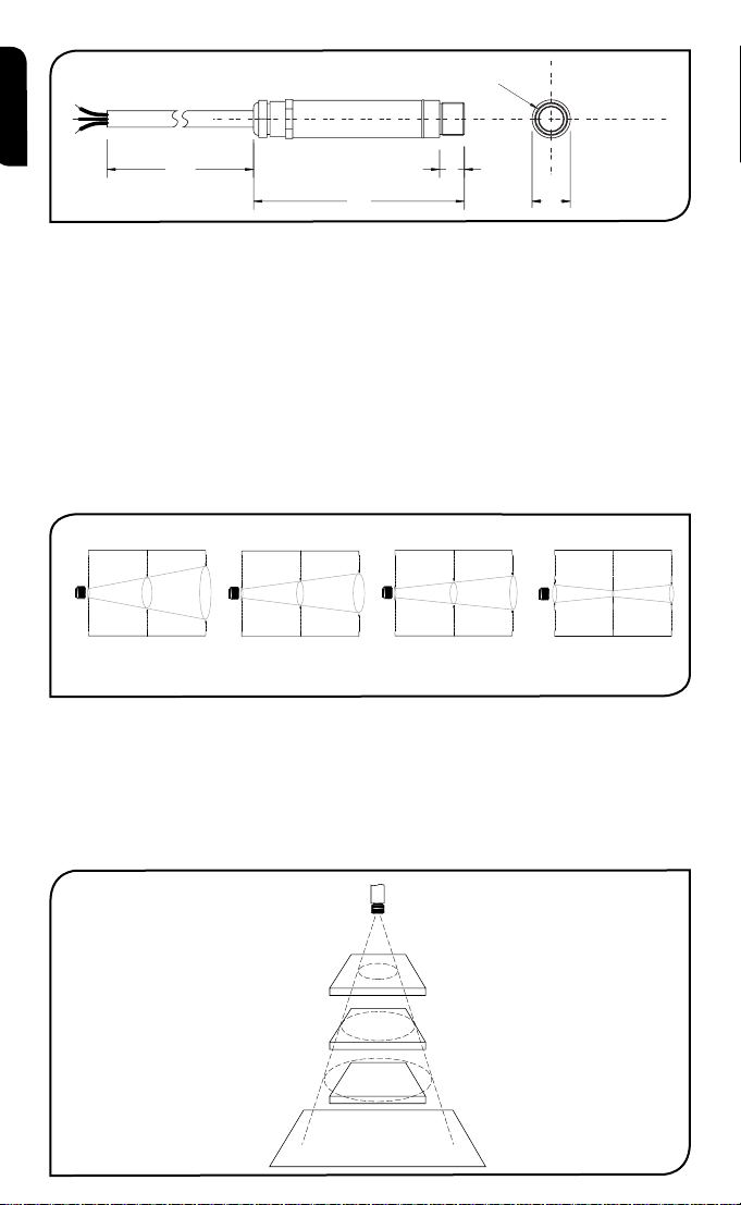
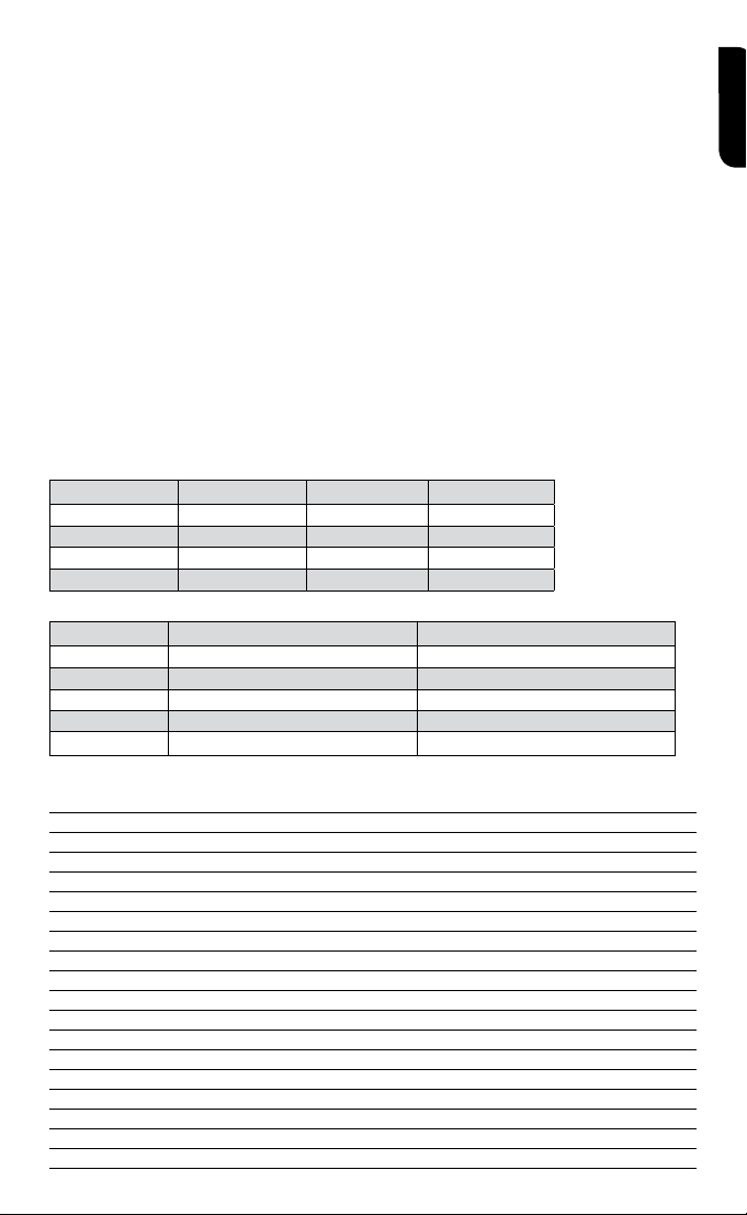
Construction Stainless Steel
Dimensions 18mm diameter x 103mm
Cable Length 1m
Weight with Cable 95g
ENVIRONMENTAL
Environmental Rating IP65
Ambient Temperature Range 0°C to 70°C
Relative Humidity 95% maximum non-condensing
›
3
Page 4
1000
103
12
18
M16 x 1mm
Distance: Sensor to object (inches)
Distance: Sensor to object (mm)
11.9
45.2
78.6
0.5
1.8
3.1
0 19.7 39.4
0
11.9
0
500 1000
Spot Dia.
(inches)
Spot Dia.
(mm)
Spot Dia.
(inches)
Spot Dia.
(mm)
Distance: Sensor to object (inches)
Distance: Sensor to object (mm)
Spot Dia.
(inches)
Spot Dia.
(mm)
Distance: Sensor to object (inches)
Distance: Sensor to object (mm)
11.9
0.5
61.9
111.9
0.5
2.4
4.4
048
0
0
5.0
0.20
100
3.9
12.5
0.49
200
7.9
100 200
D:S 15:1D:S 2:1
OS211 OS801OS151
Distance: Sensor to object (inches)
Distance: Sensor to object (mm)
11.9
28.6
45.2
0.5
1.1
1.8
0 19.7 39.4
0 500 1000
Spot Dia.
(inches)
Spot Dia.
(mm)
D:S 30:1
OS301
Sensor
BEST
GOOD
INCORREC
Background
Target greater
than spot size
Target equal to
spot size
Target smaller
than spot size
english
acceSSorieS
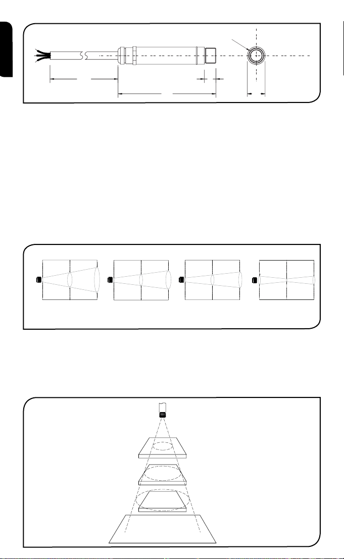
A range of accessories to suit different applications and industrial environments is available. These
may be ordered at any time and added on-site. The accessories consist of the following parts .
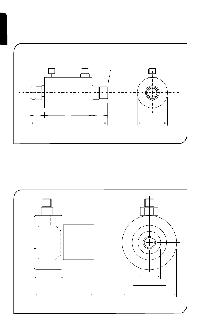
Fixed mounting bracket Adjustable mounting bracket Air purge collar
Laser sighting tool
optionS
The following options are available. Options are factory installed and must be ordered with the
OS210.
Air/water cooled housing Certificate of calibration Longer cable (30m max.)
optical cHart
The optical chart below indicates the nominal target spot diameter at any given distance from the
sensing head and assumes 90% energy.
inStallation
The installation process consists of the following stages:
Preparation Mechanical installation Electrical installation
Please read the following sections thoroughly before proceeding with the installation.
preparation
Ensure that the sensor is positioned so that it is focused on the target only.
4
›
T
Page 5
DISTANCE AND SPOT SIZE
12.0
45.0
50.0 50.0
40.0
9.0
15.0
25.0 25.0
60° Rotation 60° Rotation
60° Rotation
9.0
48.0
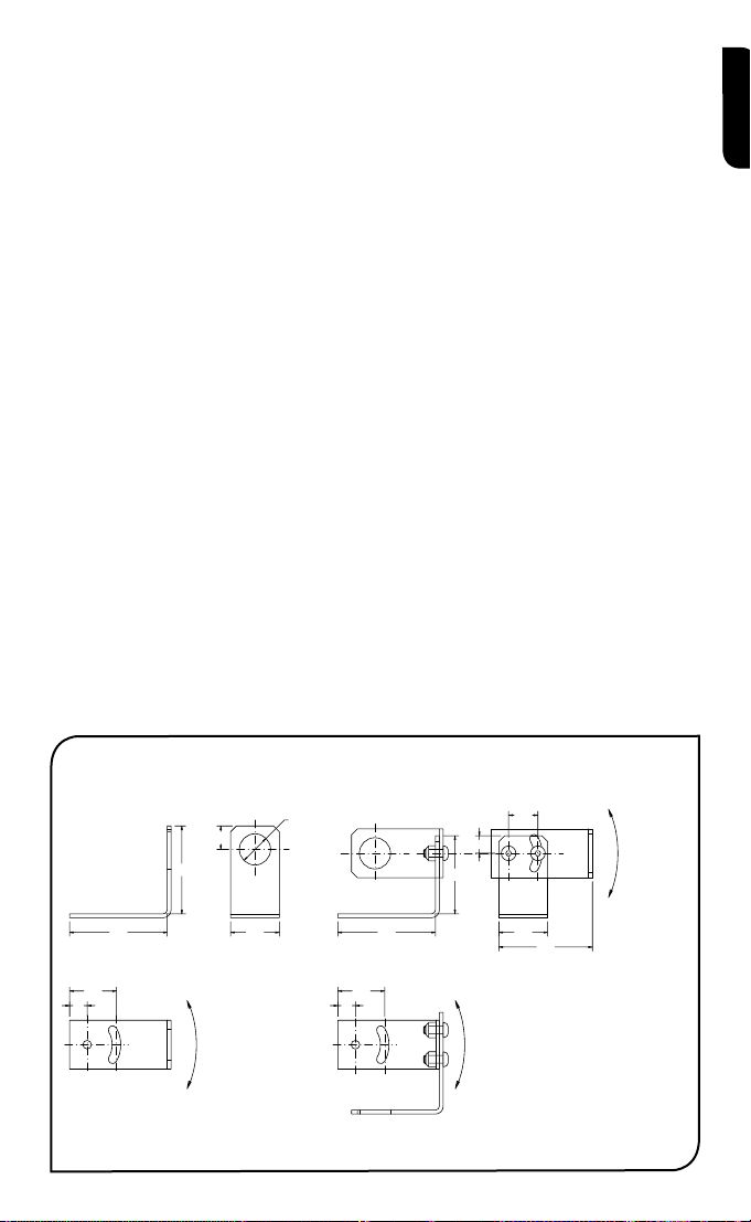
Fixed Bracket Adjustable Bracket
2 x Mounting Holes M4 Clearance 2 x Mounting Holes M4 Clearance
9.0
24.024.0
Ø16.0
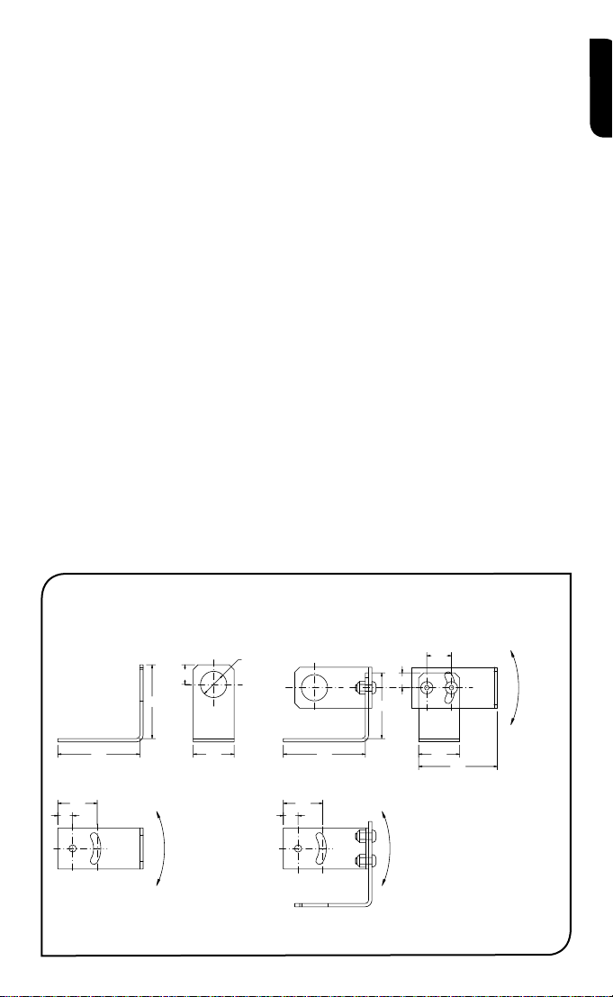
The size of the area (spot size) to be measured determines the distance between the sensor and
the target. The spot size must not be larger than the target. The sensor should be mounted so
that the measured spot size is smaller than the target.
AMBIENT TEMPERATURE
The sensor is designed to operate in ambient temperatures from 0°C to 70°C. For ambient temperatures above 70°C, an air/water-cooled housing will be required.
Avoid thermal shock. Allow 20 minutes for the unit to adjust to large changes in ambient temperature.
ATMOSPHERIC QUALITY
Smoke, fumes or dust can contaminate the lens and cause errors in temperature measurement.
In these types of environment the air purge collar should be used to help keep the lens clean.
ELECTRICAL INTERFERENCE
To minimise electromagnetic interference or ‘noise’, the sensor should be mounted away from
motors, generators and such like.
WIRING
Check the distance between the sensor and the indicating/controlling device. If necessary, the
OS210 sensor can be ordered with a longer cable attached.
POWER SUPPLY
Be sure to use a 24Vdc, (25mA) power supply.
mecHanical inStallation
All sensors come with a 1m cable and a mounting nut. The sensor can be mounted on brackets
or cut outs of your own design, or you can use the fixed and adjustable mounting bracket accessories which are shown below. Note: The OS210 sensor housing must be connected to earth at
one point, either the cable shield termination or the sensor housing.
english
›
5
Page 6
AIR/WATER COOLED HOUSING
40.0
2119 63
103
M16 x 1mm
1/8 BSP water/air connections
1/8 BSP Air connection
25
OS210-APSW
(for OS211)
50
OS210-APSN
(for OS151, OS301, OS801)
20
29
40
The air/water cooled housing shown below allows the sensor to withstand high ambient temperatures.
It is equipped with two 1/8” BSP fittings. Water temperature should be 10°C to 27°C for efficient cool-
english
ing. Chilled water below 10°C is not recommended. To avoid condensation, the air purge collar should
be used with the water-cooled housing. Water flow rate should not be more than 0.5 to 1.5 litres/min.
AIR PURGE COLLAR
The air purge collar below is used to keep dust, fumes, moisture, and other contaminants away
from the lens. It must be screwed in fully. Air flows into the 1/8” BSP fitting and out of the front
aperture. Air flow should be no more than 5 to 15 litres/min.
Clean or ‘instrument’ air is recommended.
6
›
Page 7
electrical inStallation
+-
-
+
Display/Controller
4-20mA = Target
4-20mA
Temperature
Power Supply
+-
-
+
4-20mA = Sensor
Temperature
Power Supply
-
+
mV/TC = Target
Temperature
Two-wire units
Four-wire units (options 1 to 4)
OP-
OP+
PWR+
PWR-
PWR+
PWR-
Display/Controller
Display/Controller
4-20mA
english
operation
Once the sensor is in position and the appropriate power, air, water, and cable connections are secure,
the system is ready for continuous operation by completing the following simple steps:
1. Turn on the power supply
2. Turn on the meter, chart recorder or controller
3. Read / monitor the temperature
IMPORTANT
Be aware of the following when using the sensor:
• If the sensor is exposed to significant changes in ambient temperature (hot to cold, or cold to hot),
allow 20 minutes for the temperature to stabilise before taking or recording measurements.
• Do not operate the sensor near large electromagnetic fields (e.g. around arc welders or induction
heaters).
Electromagnetic interference can cause measurement errors.
• Wire must be connected only to the appropriate terminals.
›
7
Page 8

MAINTENANCE
Our customer service representatives are available for application assistance, calibration, repair, and
english
solutions to specific problems. Contact our Service Department before returning any equipment. In
many cases, problems can be solved over the telephone. If the sensor is not performing as it should,
try to match the symptom below to the problem. If the table does not help, call Omega for further
advice.
Troubleshooting
Symptom Probable Cause Solution
No output No power to sensor Check power supply
Erroneous temperature Incorrect wire connection Check wire colour codes
Erroneous temperature Faulty sensor cable Verify cable continuity
Erroneous temperature Field of view obstruction Remove obstruction
LENS CLEANING
Keep the lens clean at all times. Any foreign matter on the lens would affect measurement accuracy.
Blow off loose particles (if not using the air purge accessory) with an air ‘puffer’.
8
›
Page 9
Les Pyromètres infra rouges de la série de OS210 mesurent des températures de -20ºC à 500ºC
et possèdent une Sortie linéaire 4..20mA, une Sortie tension ou une Sortie thermocouple. Cette
gamme des signaux de sortie est compatible avec la plus part des indicateurs, contrôleurs, enregistreur, centrale d’acquisition de données etc., sans avoir besoin d’interfaces ou de conditionnements de signal particuliers. Ils conviennent à la plupart des matériaux tels que la nourriture, le
papier, les textiles, les plastiques, le cuir, le tabac, les produits pharmaceutiques, les produits
chimiques, le caoutchouc, le charbon et l’asphalte, exceptés les matériaux à faible émissivité, par
exemple les métaux polis.
Les détecteurs OS210 sont disponibles en unités à deux ou à quatre fils.
Les détecteurs OS210 à deux fils transmettent la température cible sous forme d’une sortie à 4-20
mA et représentent une solution simple pour la plupart des applications de mesure de température
sans contact.
Les détecteurs OS210 à quatre fils transmettent la température cible sous forme d’une sortie à
0-50 mV ou thermocouple (type J, K ou T), ainsi que la température interne du détecteur sous
forme d’une sortie à 4-20 mA. On peut utiliser cette deuxième sortie afin de s’assurer que le détecteur fonctionne en-deçà des limitations de température ambiante, et ainsi éviter les dégâts potentiels causés par la surchauffe ou le refroidissement excessif. On peut l’utiliser également pour
obtenir une indication approximative de la température autour du détecteur.
SpécificationS
Tableau montrant la gamme de températures vs le champ de vision
Champ de Visée -20ºC à 100ºC 0ºC à 250ºC 0ºC à 500ºC
2:1 OS211-LT-X OS211-MT-X 15:1 OS151-LT-X OS151-MT-X OS151-HT-X
30:1 OS301-LT-X OS301-MT-X OS301-HT-X
ø5mm @ 100mm OS801-LT-X OS801-MT-X OS801-HT-X
Tableau des sorties
Model-X Température de sortie ciblée Température de détecteur ciblée
(vide) 4-20 mA –
-1 0-50 mV 4-20 mA
-2 T Thermocouple 4-20 mA
-3 J Thermocouple 4-20 mA
-4 K Thermocouple 4-20 mA
français
GÉNÉRALES
Précision ± 1% de la mesure ou ± 1°C, celui qui est le plus important
Fidélité ± 0,5% de la mesure ou ± 0,5°C, celui qui est le plus important
Emissivité 0,95 (fixée)
Temps de réponse 240ms (réponse 90%)
Réponse spectrale 8 à 14µm
Voltage d’alimentation 24V cc (max. 28V cc)
Voltage du détecteur Min. 6V cc
Impédance en boucle maximale 900 Ohms (4-20mA sortie)
Impédance de Sortie 56 Ohms (Tension ou rendement de thermocouple)
MÉCANIQUES
Construction Acier inoxydable
Dimensions 18mm diamètre x 103mm
Longueur du câble 1m
Poids avec câble 95g
ENVIRONNEMENTALES
Catégorie environnementale IP65
Echelle de température ambiante 0°C à 70°C
Humidité relative Maximum 95% non condensée
›
9
Page 10
Détecteur
LE MEILLEUR
BON
PAS BON
Fond
Cible plus grand
que la grandeur
du point
Cible même
grandeur que
le point
Cible plus petit
que la grandeur
du point
1000
103
12
18
M16 x 1mm
Distance : Détecteur / objet (inches)
Distance : Détecteur / objet (mm)
11.9
45.2
78.6
0.5
1.8
3.1
0 19.7 39.4
0
11.9
0
500 1000
Diamètre
du point
(inches)
Diamètre
du point .
(mm)
Diamètre
du point
(inches)
Diamètre
du point .
(mm)
Distance : Détecteur / objet (inches)
Distance : Détecteur / objet (mm)
Diamètre
du point
(inches)
Diamètre
du point .
(mm)
Distance : Détecteur / objet (inches)
Distance : Détecteur / objet (mm)
11.9
0.5
61.9
111.9
0.5
2.4
4.4
048
0
0
5.0
0.20
100
3.9
12.5
0.49
200
7.9
100 200
D:S 15:1D:S 2:1
Distance : Détecteur / objet (inches)
Distance : Détecteur / objet (mm)
11.9
28.6
45.2
0.5
1.1
1.8
0 19.7 39.4
0 500 1000
Diamètre
du point
(inches)
Diamètre
du point .
(mm)
D:S 30:1
OS211 OS801OS151 OS301
français
acceSSoireS
Une gamme d’accessoires pour convenir aux différentes applications et environnements industriels
est disponible. Les accessoires peuvent être commandés à tout moment et ajoutés sur place. Ils
consistent en :
Un support de fixation fixe Un support de fixation réglable Un collier de purge d’air
Outil de visée Laser
optionS
Les options suivantes sont disponibles : Les options sont installées en usine et doivent être commandées avec le détecteur OS210.
Boîtier refroidi à l’air/eau Certificat de calibrage Câble plus long (30m max.)
taBleaU optiQUe
Le tableau optique ci-dessous indique le diamètre du point cible nominal à n’importe quelle distance de la tête de détection et assume 90% d’énergie.
inStallation
Le processus d’installation consiste aux étapes suivantes :
Préparation Installation mécanique Installation électrique
Il faut lire les sections suivantes attentivement avant de commencer l’installation.
préparation
S’assurer que le détecteur est mis en place pour qu’il ne se concentre que sur la cible.
10
›
Page 11
DISTANCE ET TAILLE DU POINT
12.0
45.0
50.0 50.0
40.0
9.0
15.0
25.0 25.0
9.0
48.0
9.0
24.024.0
Ø16.0
Rotation 60° Rotation 60°
Rotation 60°
Support fixe Support réglable
2 x trous de montage, jeu M4 2 x trous de montage, jeu M4
La taille de la zone (taille du point) qui doit être mesurée détermine la distance entre le détecteur et
la cible. La taille du point ne doit pas être plus grande que la cible. Le détecteur devrait être monté
de façon à ce que la taille du point mesuré est plus petite que la cible.
TEMPÉRATURE AMBIANTE
Le détecteur est conçu pour fonctionner en températures ambiantes de 0°C à 70°C. Pour les
températures ambiantes supérieures à 70°C, un boîtier refroidi à l’air/eau est nécessaire.
Eviter les chocs thermiques. Allouer 20 minutes au thermomètre, pour qu’il s’adapte à
d’importantes fluctuations de température ambiante.
QUALITÉ ATMOSPHÉRIQUE
La fumée, les vapeurs ou la poussière peuvent contaminer la lentille et provoquer des erreurs dans
la mesure de température. Dans ces genres d’environnement, le collier de purge d’air devrait être
utilisé pour aider à garder la lentille propre.
INTERFÉRENCE ÉLECTRIQUE
Pour réduire l’interférence électromagnétique ou ‘bruit’, le détecteur devrait être monté à l’écart de
moteurs, générateurs, et autres appareils similaires.
CÂBLAGE
Vérifier la distance entre le détecteur et l’appareil d’indication / de contrôle. Si nécessaire, le
détecteur OS210 peut être commandé avec un câble attaché plus long.
ALIMENTATION ÉLECTRIQUE
S’assurer qu’une alimentation électrique de 24Vcc (25mA) est utilisée.
inStallation mécaniQUe
Tous les détecteurs sont fournis avec un câble d’un mètre et un boulon de fixation. Le détecteur
peut être monté sur un support ou sur des découpes de votre propre conception ou bien les
accessoires de support fixe et réglable, qui sont montrés ci-dessous, peuvent être utilisés. Nota: Il
faut que le détecteur soit connecté à la terre à un seul point, soit au blindage du câble, soit au
boîtier du détecteur.
français
11
›
Page 12

BOÎTIER REFROIDI À L’AIR/EAU
40.0
2119 63
103
M16 x 1mm
1/8 BSP Raccords Air/Eau
20
29
40
1/8 BSP Raccord Air
25
OS210-APSW
(for OS211)
50
OS210-APSN
(for OS151, OS301, OS801)
Le boîtier refroidi à l’air/l’eau montré ci-dessous permet au détecteur de resister à des
temperatures ambiantes élevées. Il est équipé de deux emmanchements de 1/8’’ BSP.
français
La température de l’eau devrait être entre 10°C et 27°C pour un refroidissement efficace.
L’eau refroidie en dessous de 10°C n’est pas recommandée. Pour éviter la condensation, le collier de purge d’air devrait être utilisé avec le boîtier refroidi à l’eau. Le débit
d’eau ne devrait pas dépasser 0,5 à 1,5 litres/min.
COLLIER DE PURGE D’AIR
Le collier de purge d’air ci-dessous est utilisé pour garder la poussière, les vapeurs, l’humidité et
autres contaminants à l’écart de la lentille. Il doit être entièrement vissé. L’air s’écoule dans
l’emmanchement de 1/8’’ BSP et sort par l’ouverture frontale. Le débit d’air ne devrait pas
dépasser 5 à 15 litres/min.
Il est recommandé d’utiliser de l’air propre ou pour les appareils.
12
›
Page 13

inStallation èlectriQUe
+-
-
+
4-20mA = Température cible
4-20mA
+-
-
+
4-20mA = Température détecteu
-
+
mV/TC = Température cible
Unités à deux fils
Unités à quatre-fils (options 1 à 4)
OP-
OP+
PWR+
PWR-
PWR+
PWR-
4-20mA
Afficheur/
Contrôleur
Afficheur/
Contrôleur
Afficheur/
Contrôleur
Alimentation électrique
Alimentation électrique
français
r
FONCTIONNEMENT
Une fois que le détecteur est en place et que les connexions appropriées d’alimentation, d’air,
d’eau et de câbles sont bien fixées, le système est prêt pour fonctionner en continu en complétant
les simples étapes suivantes :
1. Mettre en route l’alimentation électrique
2. Mettre en route le compteur,
l’enregistreur de tableau ou le contrôleur
3. Lire / contrôler la temperature
IMPORTANT
Il faut faire attention aux suivants lors de l’utilisation du détecteur :
• Si le détecteur est exposé à des changements significatifs de température ambiante (chaud à
froid, ou froid à chaud), avant de prendre ou d’enregistrer des mesures attendre 20 minutes
que la température se stabilise.
• Ne pas faire fonctionner le détecteur près d’importants champs électromagnétiques (par exem-
ple autour d’un arc de soudage ou d’appareils chauffants à induction). Des interférences
électromagnétiques peuvent provoquer des erreurs de mesure.
• Le câble ne doit être relié qu’à des terminaux appropriés.
13
›
Page 14

ENTRETIEN
Les représentants du service clientèle sont disponibles pour aider, calibrer, réparer et résoudre des
problèmes particuliers. Contacter le service technique avant de retourner l’équipement. Dans
français
beaucoup de cas, les problèmes peuvent être résolus par téléphone. Si le détecteur ne fonctionne
pas comme il le devrait, essayer de faire correspondre le symptôme ci-dessous au problème. Si le
tableau n’aide pas, appeler Omega pour plus de renseignement.
Diagnostic de défaillances
Symptôme Cause probable Solution
Pas de sortie Pas d’alimentation au détect-
eur
Température erronée Connexion incorrecte du
câble
Vérifier l’alimentation électrique
Vérifier les codes de couleurs du câble
Température erronée Câble du détecteur défaillant Vérifier la continuité du
câble
Température erronée Obstruction champs de vue Retirer l’obstruction
NETTOYAGE DE LA LENTILLE
Garder la lentille propre à tout moment. Toute matière étrangère sur la lentille affecterait la précision
de la mesure. Souffler les particules libres (si l’accessoire de purge d’air n’est pas utilisé) avec un
‘soufflet’.
14
›
Page 15

Die kontaklosen Infrarot-Sensoren der OS210-Serie messen Temperaturen von -20ºC bis 500ºC
und sind entweder mit einem linearen 4...20mA- Ausgang, einem Spannungsausgang oder einem
Thermoelement-Ausgang ausgestattet. Dieser Ausgangsbereich ist mit fast jedem Anzeigegerät,
Prozeßkontroller, Speicherschreiber, Datenlogger und ähnlichen Messumformern kompatibel. Eine
besondere Schnittstelle oder Signalverarbeitung ist nicht erforderlich. Die OS210 sind für die
meisten Materialien wie Nahrungsmittel, Papier, Textilien, Kunststoffe, Leder, Tabak, Arzneimittel,
Chemikalien, Gummi, Kohle und Asphalt geeignet, nicht aber für Materialien mit niedrigem
Emissionsvermögen wie z. B. polierte Metalle.
OS210-Sensoren sind als Zweidraht- oder Vierdraht-Einheiten erhältlich.
Zweidraht-OS210-Sensoren übermitteln die Zieltemperatur als 4-20 mA-Ausgang und bieten eine
einfache Lösung für die meisten kontaktlosen Anwendungen zur Temperaturmessung.
Vierdraht-OS210-Sensoren übermitteln die Zieltemperatur als 0-50 mV- oder ThermoelementAusgang (Typ J, K oder T) sowie die innere Sensortemperatur als 4-20 mA-Ausgang. Dieser zweite
Ausgang kann genutzt werden, um sicherzustellen, dass der Sensor innerhalb der korrekten
Grenzwerte für die Umgebungstemperatur genutzt wird, sowie um Schäden durch Überhitzung
oder Unterkühlung zu verhindern. Er kann auch genutzt werden, um einen Näherungswert für die
Temperatur der Luft um den Sensor zu erhalten.
Spezifikation
Temperaturbereich im Verhältnis zur Sichtfeldtabelle
Bildfeld -20ºC bis 100ºC 0ºC bis 250ºC 0ºC bis 500ºC
2:1 OS211-LT-X OS211-MT-X 15:1 OS151-LT-X OS151-MT-X OS151-HT-X
30:1 OS301-LT-X OS301-MT-X OS301-HT-X
ø5mm @ 100mm OS801-LT-X OS801-MT-X OS801-HT-X
Ausgangstabelle
Modell-X Zieltemperaturausgang Sensortemperaturausgang
(leer) 4-20 mA –
-1 0-50 mV 4-20 mA
-2 T Thermoelement 4-20 mA
-3 J Thermoelement 4-20 mA
-4 K Thermoelement 4-20 mA
deutsch
ALLGEMEIN
Messunsicherheit ±1% des Messwerts oder ±1ºC (je nachdem, welcher Wert größer ist)
Wiederholgenauigkeit ±0,5% des Messwerts oder ±0,5ºC (je nachdem, welcher Wert größer ist)
Emissionsvermögen 0,95 (festgelegt)
Reaktionszeit 240ms (90% Reaktion)
Spektralempfindlichkeit 8 bis 14µm
Speisespannung 24V Gleichstrom (28V Gleichstrom max.)
Sensorspannung 6V Gleichstrom min.
Maximale Kreis-Impedanz 900 Ohm (4-20mA Leistung)
Ausgangsimpedanz 56 Ohm (Spannung oder Thermoelementausgang)
MECHANISCHE DATEN
Konstruktion Rostfreier Stahl
Abmessungen 18mm Durchmesser x 103mm
Kabellänge 1m
Gewicht mit Kabel 95g
UMWELTBESTIMMUNGEN
Umwelttechnische Einstufung IP65
Umgebungstemperaturbereich 0ºC bis 70ºC
Relative Feuchte höchstens 95%, ohne Kondensation
15
›
Page 16

1000
103
12
18
M16 x 1mm
11.9
45.2
78.6
0.5
1.8
3.1
0 19.7 39.4
0
11.9
0
500 1000
Zielpunktdurchmesser
(inches)
Zielpunktdurchmesser
(mm)
Entfernung:
zwischen Sensor und Gegenstand (inches)
Entfernung:
zwischen Sensor und Gegenstand (mm)
Zielpunktdurchmesser
(inches)
Zielpunktdurchmesser
(mm)
Entfernung:
zwischen Sensor und Gegenstand (inches)
Entfernung:
zwischen Sensor und Gegenstand (mm)
Zielpunktdurchmesser
(inches)
Zielpunktdurchmesser
(mm)
Entfernung:
zwischen Sensor und Gegenstand (inches)
Entfernung:
zwischen Sensor und Gegenstand (mm)
Zielpunktdurchmesser
(inches)
Zielpunktdurchmesser
(mm)
Entfernung:
zwischen Sensor und Gegenstand (inches)
Entfernung:
zwischen Sensor und Gegenstand (mm)
11.9
0.5
61.9
111.9
0.5
2.4
4.4
048
0
0
5.0
0.20
100
3.9
12.5
0.49
200
7.9
100 200
D:S 15:1D:S 2:1
11.9
28.6
45.2
0.5
1.1
1.8
0 19.7 39.4
0 500 1000
D:S 30:1
OS211 OS801OS151 OS301
Sensor
AM BESTEN
GUT
FALSCH
Hintergrund
Ziel größer als
Zielpunktgröße
Ziel entspricht
Zielpunktgröße
Ziel kleiner als
Zielpunktgröße
deutsch
zUBeHör
Eine Reihe von Zubehörteilen für unterschiedliche Anwendungen und industrielle Umgebungen
sind erhältlich.
Die Zubehörteilen können jederzeit bestellt und vor Ort installiert werden. Die folgenden
Zubehörteile sind lieferbar:
Feste Halterung Verstellbare Halterung Luftspülmanschette
Laserzielstrahl
OptiOnen
Die folgenden Optionen sind verfügbar. Die Optionen werden werksmäßig installiert und müssen
zusammen mit dem OS210-Sensor bestellt werden.
Luft-/wassergekühltes Gehäuse Eichbescheinigung Längeres Kabel (max. 30m)
optiScHeS DiaGramm
Das optische Diagramm unten gibt den nominellen Zielpunktdurchmesser in einer beliebigen
Entfernung vom Messkopf an. Es werden 90% Energie angenommen.
inStallation
Der Installationsprozess besteht aus den folgenden Phasen:
Vorbereitung Mechanische Installation Elektrische Installation
Bitte lesen Sie sich die folgenden Abschnitte sorgfältig durch, bevor Sie mit der Installation beginnen.
vorBereitUnG
Achten Sie darauf, dass der Sensor nach dem Aufstellen nur auf das Ziel weist.
›
16
Page 17

ENTFERNUNG UND ZIELPUNKTGRÖSSE
12.0
45.0
50.0 50.0
40.0
9.0
15.0
25.0 25.0
9.0
48.0
9.0
24.024.0
Ø16.0
60° Drehung 60° Drehung
60° Drehung
Feste Halterung Verstellbare Halterung
2 x Befestigungsbohrungen M4-Gewinde 2 x Befestigungsbohrungen M4-Gewinde
Die Größe des Messbereichs (Zielpunktgröße) bestimmt die Entfernung zwischen Sensor und Ziel.
Die Zielpunktgröße darf die Zielgröße nicht übersteigen. Der Sensor sollte so aufgestellt werden, dass
die gemessene Zielpunktgröße kleiner ist als das Ziel.
UMGEBUNGSTEMPERATUR
Der Sensor ist für Umgebungstemperaturen zwischen 0°C und 70°C konzipiert. Bei
Umgebungstemperaturen über 70ºC ist ein luft-/wassergekühltes Gehäuse erforderlich.
Vermeiden Sie Wärmeschocks. Warten Sie 20 Minuten, damit sich das Gerät an starke
Veränderungen in der Umgebungstemperatur gewöhnen kann.
LUFTQUALITÄT
Rauch, Dämpfe oder Staub können die Linse verunreinigen und zu Fehlern bei der
Temperaturmessung führen. In derartigen Umgebungen sollte die Luftspülmanschette verwendet
werden, damit die Linse sauber bleibt.
ELEKTRISCHE STÖRUNGEN
Um elektromagnetische Störungen oder “Lärm” auf ein Minimum zu reduzieren, sollte der Sensor entfernt von Motoren, Generatoren und ähnlichen Geräten aufgestellt werden.
VERKABELUNG
Überprüfen Sie die Entfernung zwischen dem Sensor und dem Anzeige-/Steuergerät. Bei Bedarf
kann der OS210-Sensor mit längerem Kabel geliefert werden.
NETZSPANNUNG
Achten Sie darauf, dass Sie 24V Gleichstrom (25mA) verwenden..
mecHaniScHe inStallation
Alle Sensoren werden mit einem 1m langem Kabel und einer Befestigungsmutter geliefert. Der
Sensor kann an Halterungen oder mit lhrer eigenen Konstruktion befestigt werden. Oder verwenden Sie die unten abgebildeten festen und verstellbaren Zubehörteile für die Halterung.
Hinweis: Der Sensor darf nur an einem Punkt geerdert sein, nämlich entweder an der
Kabelabschirmung oder am Sensorgehäuse.
deutsch
›
17
Page 18

LUFT-/WASSERGEKÜHLTE GEHÄUSE
40.0
2119 63
103
M16 x 1mm
1/8-BSP-Wasser-/Luftverbindungen
20
29
40
1/8-BSP-Luftverbindung
25
OS210-APSW
(for OS211)
50
OS210-APSN
(for OS151, OS301, OS801)
Aufgrund des im Folgenden dargestellten luft-/wassergekühlten Gehäuses kann der Sensor hohen
Umgebungstemperaturen standhalten. Der Sensor ist mit zwei 1/8-Zoll-Bsp-Verbindungsstücken
deutsch
ausgestattet. Um eine wirksame Kühlung zu gewährleisten, sollte die Wassertemperatur zwischen
10ºC und 27ºC betragen. Gekühltes Wasser unter 10ºC ist nicht zu empfehlen. Um Kondensation
zu vermeiden, sollte die Luftspülmanschette in Verbindung mit dem wassergekühlten Gehäuse eingesetzt werden. Den Wasserdurchfluss sollte nicht mehr als 0,5 bis 1,5 Liter/Min. betragen.
LUFTSPÜLMANSCHETTE
Die unten abgebildete Luftspülmanschette hält Staub, Dämpfe, Feuchtigkeit und andere
Verunreinigungen von der Linse fern. Die Manschette muss vollständig eingeschraubt werden. Luft
strömt in das 1/8-Zoll-Bsp-Verbindungsstück und aus der vorderen Öffnung. Der Luftstrom sollte
nicht mehr als 5 bis 15 Liter/Min. betragen.
Es wird reine Luft oder “Hilfsluft” empfohlen.
18
›
Page 19

elektriScHe inStallation
+-
-
+
4-20 mA = Zieltemperatur
4-20mA
+-
-
+
4-20 mA = Sensortemperatu
-
+
mV/TC = Zieltemperatur
Zweidraht-Einheiten
Vierdraht-Einheiten (Optionen 1 bis 4)
OP-
OP+
PWR+
PWR-
PWR+
PWR-
Display/Controller
4-20mA
Stromzuführung
Stromzuführung
Display/
Controller
Display/
Controller
deutsch
r
BETRIEB
Wenn der Sensor aufgestellt ist und die entsprechenden Strom-, Luft-, Wasser- und Kabelanschlüsse
gesichert sind, kann das System mit den folgenden einfachen Schritten auf Dauerbetrieb eingestellt
werden:
1. Die Stromversorgung einschalten
2. Das Messgerät, den Rekorder
oder Messumformer einschalten
3. Die Temperatur ablesen / überwachen
WICHTIG
Achten Sie beim Einsatz des Sensors auf die folgenden Punkte:
• Wenn der Sensor erheblichen Temperaturschwankungen ausgesetzt wird (heiss/kalt oder kalt/heiss),
sind 20 Minuten notwendig, damit sich die Temperatur vor der Temperaturmessung und -aufzeichnung stabilisieren kann.
• Betreiben Sie den Sensor nicht in der Nähe großer elektromagnetischer Felder (z.B. von
Lichtbogenschweißgeräten oder Induktionsheizgeräten). Elektromagnetische Störungen können zu
Messfehlern führen.
• Die Kabel dürfen nur mit den korrekten Anschlüssen verbunden werden.
19
›
Page 20

WARTUNG
Unsere Kundendienstmitarbeiter können bei Anwendungen, kalibrierung, Reparaturen und Lösung konkreter Probleme helfen. Setzen Sie sich bitte mit unserer Kundendienstabteilung in Verbindung, bevor Sie
deutsch
Geräte zurücksenden. Häufig können Probleme telefonisch gelöst werden.Wenn der Sensor nicht ordnungsgemäß funktioniert, versuchen Sie, das unten aufgeführte Symptom dem entsprechenden Problem
zuzuordnen. Wenn die Tabelle nicht weiterhilft, kann Ihnen Omega möglicherweise telefonisch weitere
Tipps geben.
Störungssuche
Symptom Wahrscheinliche Ursache Lösung
Kein Ausgangssigna Keine Stromzufuhr am Sensor Stromanschluss überprüfen
Falsche Temperatur Falscher Kabelanschluss Kabelfarbcode überprüfen
Falsche Temperatur Fehlerhaftes Sensorkabel Kabelkontinuität überprüfen
Falsche Temperatur Blickfeld blockiert Blockierung entfernen
REINIGEN DER LINSE
Halten Sie die Linse stets sauber. Fremdkörper auf der Linse würden die Messgenauigkeit beeinträchtigen. Blasen Sie lose Partikel mit einem Gebläse von der Linse (sofern Sie nicht die Luftspülmanschette
verwenden).
20
›
Page 21

El sensor de infrarrojos sin contacto OS210, mide temperaturas desde -20 a 500º C y dispone de
salida 4-20 mA., voltaje o termopar. Este rango de señales de salida es compatible con la mayoría de indicadores, controladores, registradores, data logers, etc., sin necesidad de una interconexión especial o acondicionamiento de señal. Son adecuados para la mayoría de las materias,
tales como alimentos, papel, telas, plásticos, cuero, tabaco, medicinas, productos químicos,
caucho, carbón y asfalto; sin embargo, no lo son para materiales con una baja emisividad, por
ejemplo, los metales pulidos.
Existen versiones de los sensores OS210 de dos y cuatro hilos.
Los sensores OS210 de dos hilos transmiten la temperatura objetivo como una salida de 4-20 mA
y suponen una solución simple para la mayoría de las aplicaciones de medición de temperatura sin
contacto.
Los sensores OS210 de cuatro hilos transmiten la temperatura objetivo como una salida de 0-50
mV o como salida de termopar (tipo J, K o T) más la temperatura interna del sensor como una
salida de 4-20 mA. Esta segunda salida se puede utilizar para garantizar que el sensor se está
utilizando dentro de los límites adecuados de temperatura ambiental y se evitan posibles daños
por recalentamiento o subenfriamiento. También se pueden utilizar para proporcionar una indicación aproximada de la temperatura del aire que rodea al sensor.
caracteríSticaS
Tabla de rango de temperaturas frente a campo de visualización
Campo Visual -20ºC a 100ºC 0ºC a 250ºC 0ºC a 500ºC
2:1 OS211-LT-X OS211-MT-X 15:1 OS151-LT-X OS151-MT-X OS151-HT-X
30:1 OS301-LT-X OS301-MT-X OS301-HT-X
ø5mm @ 100mm OS801-LT-X OS801-MT-X OS801-HT-X
Tabla de salidas
Modelo-X Salida de temperatura objetivo Salida de temperatura del sensor
(en blanco) 4-20 mA –
-1 0-50 mV 4-20 mA
-2 T Termocoppia 4-20 mA
-3 J Termocoppia 4-20 mA
-4 K Termocoppia 4-20 mA
español
GENERAL
Precisión ±1% de lectura o ±1ºC, la cifra que sea mayor
Repetibilidad ±0,5% de lectura o ±0,5ºC, la cifra que sea mayor
Emisividad 0,95 (fijada)
Tiempo de respuesta 240ms (90% respuesta)
Respuesta espectral 8 a 14µm
Tensión de alimentación 24Vcc (máx. 28Vcc)
Tensión del sensor mín. 6Vcc
Impedancia máxima de circuito 900 Ohmios (4-20mA Salida)
Impedancia de Salida 56 Ohmios (Voltaje o salida del termopar)
MECÁNICA
Construcción Acero inoxidable
Dimensiones 18mm de diámetro x 103mm
Longitud de cable 1m
Peso con cable 95g
AMBIENTE
Valoración ambiental IP65
Gama de temperatura ambiental 0ºC a 70ºC
Humedad relativa 95% máximo sin condensación
21
›
Page 22

Sensor
MEJOR
BUENO
INCORRECTO
Fondo
Diana superior al
tamaño del punto
Diana igual al
tamaño del punto
Diana inferior al
tamaño del punto
1000
103
12
18
M16 x 1mm
Distancia: sensor a objeto (inches)
Distancia: sensor a objetot (mm)
11.9
45.2
78.6
0.5
1.8
3.1
0 19.7 39.4
0
11.9
0
500 1000
Diámetro del
punto de diana
(inches)
Diámetro del
punto de diana
(mm)
Diámetro del
punto de diana
(inches)
Diámetro del
punto de diana
(mm)
Distancia: sensor a objeto (inches)
Distancia: sensor a objetot (mm)
Diámetro del
punto de diana
(inches)
Diámetro del
punto de diana
(mm)
Distancia: sensor a objeto (inches)
Distancia: sensor a objetot (mm)
11.9
0.5
61.9
111.9
0.5
2.4
4.4
048
0
0
5.0
0.20
100
3.9
12.5
0.49
200
7.9
100 200
D:S 15:1D:S 2:1
Distancia: sensor a objeto (inches)
Distancia: sensor a objetot (mm)
11.9
28.6
45.2
0.5
1.1
1.8
0 19.7 39.4
0 500 1000
Diámetro del
punto de diana
(inches)
Diámetro del
punto de diana
(mm)
D:S 30:1
OS211 OS801OS151 OS301
español
acceSorioS
Se encuentra disponible una gama de accesorios para las distintas aplicaciones y ambientes
industriales. Los accesorios pueden pedirse en cualquier momento y añadirse en el mismo recinto.
Éstos consisten en las piezas a siguientes:
Consola fija para el montaje Consola regulable de montaje Aro de purga de aire
Herramienta de enfoque laser
opcioneS
Se encuentran a disposición las siguientes opciones. Las opciones son instaladas en la fábrica y
deben pedirse con el sensor OS210.
Caja de enfriamiento por aire/agua Certificado de calibración Cable más largo (máx. de 30m)
cUaDro Óptico
El cuadro óptico de debajo indica el diámetro nominal del punto de diana a una distancia dada de
la cabeza sensora y asume 90% de energía.
inStalaciÓn
El proceso de instalación consiste en las siguientes etapas:
Preparación Instalación mecánica Instalación eléctrica
Leer las siguientes secciones con detenimiento antes de proceder a la instalación.
preparaciÓn
Asegurarse de que el sensor se coloca de manera que esté enfocando solamente a la diana.
22
›
Page 23

DISTANCIA Y TAMAÑO DE LA ZONA DE MEDICIÓN
12.0
45.0
50.0 50.0
40.0
9.0
15.0
25.0 25.0
9.0
48.0
9.0
24.024.0
Ø16.0
Rotación 60° Rotación 60°
Rotación 60°
Soporte fijo Soporte regulable
2 x Holgura de orificios de montaje M4 2 x Holgura de orificios de montaje M4
El tamaño de la zona de medición a medir determina la distancia entre el sensor y la diana. El
tamaño de la zona de medición no debe ser mayor que el de la diana. El sensor debe ser instalado
de manera que la zona de medición determinada sea menor que la diana.
LA TEMPERATURA AMBIENTE
El sensor está diseñado para funcionar en temperaturas ambientes desde 0ºC hasta 70ºC. Para
las temperaturas ambientes superiores a 70ºC, se hará necesario una caja de enfriamiento por
aire/agua.
Evitar un cambio brusco de temperatura. Dejar pasar 20 minutos para que la unidad se ajuste a
los grandes cambios de temperatura ambiente.
CALIDAD ATMOSFÉRICA
Los humos o el polvo pueden contaminar la lente y causar errores en la medición de la temperatura. El aro de purga de aire debe usarse en ambientes de este tipo para ayudar a mantener la
lente limpia.
INTERFERENCIA ELÉCTRICA
Para reducir al mínimo la interferencia electromagnética o el “ruido”, el sensor debe ser instalado
alejado de motores, generadores o similares.
CONEXIONES ELÉCTRICAS
Comprobar la distancia entre el sensor y el dispositivo indicador/controlador. Si es necesario, el
sensor OS210 se puede pedir con el cable que viene adosado, más largo.
SUMINISTRO ELÉCTRICO
Asegurarse de usar un suministro eléctrico de 24Vcc, (25mA).
inStalaciÓn mecánica
Todos los sensores vienen con 1 metro de cable y una tuerca de montaje. OS210 sensor puede
ser instalado en una consola o dispositivos de diseño propio, o puede usar los accesorios de
consola fija y regulable de montaje que se muestran debajo. Nota: El sensor debe ser conectado
a la tierra en un único punto, en el blindaje del cable o en la carcasa del sensor.
español
›
23
Page 24

CAJA DE ENFRIAMIENTO POR AIRE/AGUA
40.0
2119 63
103
M16 x 1mm
Conexiones de agua/aire de BSP
(hilo de rosca en paralelo de British Standards)
de 1/8 de pulgada.
20
29
40
Conexiones de aire de BSP
(hilo de rosca en paralelo de British Standards)
de 1/8 de pulgada.
25
OS210-APSW
(for OS211)
50
OS210-APSN
(for OS151, OS301, OS801)
La caja de enfriamiento por aire/agua mostrada a continuación permite al sensor soportar temperaturas ambientes elevadas. Se encuentra equipado de dos accesorios BSP (hilo de rosca en
español
paralelo de British Standards) de 1/8 de pulgada. La temperatura del agua debe ser de 10ºC a
27ºC para un enfriamiento eficaz. No se recomienda agua fría por debajo de los 10ºC. Para evitar
una condensación, el aro de purga de aire debe usarse con la caja de enfriamiento por agua. El
caudal de agua no debe ser superior a 0,5 a 1,5 litros/min.
ARO DE PURGA DE AIRE
El aro de purga de aire a continuación se usa para mantener el polvo, los humos, la humedad y
otros contaminantes alejados de la lente. Debe atornillase completamente. El aire fluye hacia
adentro del accesorio BSP de 1/8 de pulgada y hacia afuera de la abertura frontal. El flujo de aire
no debe ser superior a 5 a 15 litros/min.
Se recomienda aire limpio o “para instrumentos”.
24
›
Page 25

inStalaciÓn eléctrica
+-
-
+
4-20 mA = Temperatura objetivo
4-20mA
+-
-
+
4-20 mA = Temperatura del sensor
-
+
mV/TC = Temperatura objetivo
Equipos de dos hilos
Equipos de cuatro hilos (opciones 1 a 4)
OP-
OP+
PWR+
PWR-
PWR+
PWR-
4-20mA
Indicador/
Controlador
Indicador/
Controlador
Indicador/
Controlador
Suministro eléctrico
Suministro eléctrico
español
FUNCIONAMIENTO
Una vez que el sensor está en posición y el suministro eléctrico, el aire, el agua y las conexiones
de cables apropiadas están seguras, el sistema está listo para el funcionamiento continuo, una
vez se completen los sencillos pasos siguientes:
1. Encender el suministro eléctrico
2. Encender el medidor, el registro gráfico o el controlador
3. Leer / controlar la temperatura
IMPORTANTE
Prestar atención a lo siguiente al usar el sensor:
• Si el sensor se expone a cambios significativos de temperatura ambiental (de caliente a fr’o o
de fr’o a caliente), dejar pasar 20 minutos para que la temperatura se estabilice antes de tomar
o registrar temperaturas.
• No hacer funcionar el sensor cerca de grandes campos electromagnéticos (ejemplo, cerca de
soldadoras por arco o calentadores por corrientes de inducción). Las interferencias electromagnéticas pueden causar errores de medición.
• Los hilos deben ser conectados solamente a las terminales apropiadas.
25
›
Page 26

MANTENIMIENTO
Nuestros representantes de servicio al cliente están a su disposición para asistirles en aplicaciones, calibración, reparación y soluciones a problemas específicos. Contactar nuestro
español
Departamento de servicio antes de devolver el equipo. En muchos casos, los problemas pueden
resolverse por teléfono. Si el sensor no funciona como debiera, intentar encontrar el síntoma de
entre los siguientes para identificar su problema. Si la tabla no le sirve de ayuda, llamar a Omega
para mayor asistencia.
Identificación de problemas
Síntoma Causa probable Solución
No funciona No hay suministro eléctrico al
sensor
Temperatura errónea Conexión de cables
incorrecta
Comprobar el suministro
eléctrico
Comprobar los códigos
de color de los cables
Temperatura errónea Cable sensor defectuoso Confirmar la continuidad
de los cables
Temperatura errónea Obstrucción del campo visual Retirar obstrucción
LIMPIEZA DE LA LENTE
Mantener la lente limpia en todo momento. Cualquier materia extraña en la lente afectaría la precisión de medición. Soplar las partículas sueltas (si no se usa el accesorio de purga de aire) con
un ‘soplador’ de aire.
26
›
Page 27

I sensori di temperatura infrarosso senza-contatto serie OS210 misurano temperature comprese
tra -20°C e +500°C e possono fornire un’uscita lineare 4..20mA, un’uscita in Volt oppure uscita
con segnale termocoppia. Questa gamma di segnali di uscita è compatibile con qualsiasi indicatore, regolatore, registratore, data logger..., senza bisogno di speciale interfaccia o condizionamento di segnale. Sono idonei per la maggior parte di materiali quali alimentari, carta, tessuti,
plastiche, pellame, tabacco, prodotti farmaceutici, chimici, gomma, carbone e asfalto; ma non per
materiali a bassa emissività come ad esempio metalli levigati.
I sensori OS210 sono disponibili come unità a due o quattro cavi.
I sensori OS210 a due cavi trasmettono la temperatura mirata come uscita di 4-20 mA e offrono
una soluzione semplice per la maggior parte delle applicazioni per la misurazione delle temperature
senza-contatto.
I sensori OS210 a quattro cavi trasmettono la temperatura mirata come uscita di 0-50 mV o termocoppia (tipo J, K o T) nonché la temperatura del sensore interno come uscita a 4-20 mA.
Questo secondo uscita può essere usato per garantire che il sensore sia operato nei limiti di temperatura ambiente adeguati e impedire danni provocati dal surriscaldamento o raffreddamento
eccessivo. Può anche essere usato per ottenere un’indicazione approssimativa della temperatura
dell’aria intorno al sensore.
Data tecnici
Tabella gamma di temperatura vs campo-vista
Risoluzione Ottica -20ºC a 100ºC 0ºC a 250ºC 0ºC a 500ºC
2:1 OS211-LT-X OS211-MT-X 15:1 OS151-LT-X OS151-MT-X OS151-HT-X
30:1 OS301-LT-X OS301-MT-X OS301-HT-X
ø5mm @ 100mm OS801-LT-X OS801-MT-X OS801-HT-X
Tabella di uscita
Modello-X Uscita temperatura mirata Uscita temperatura sensore
(vuoto) 4-20 mA –
-1 0-50 mV 4-20 mA
-2 T Termopar 4-20 mA
-3 J Termopar 4-20 mA
-4 K Termopar 4-20 mA
italiano
GENERALE
Precisione ±1% della lettura o ±1ºC al massimo
Ripetibilità ±0.5% della lettura o ±0.5ºC al massimo
Coefficiente di emissione 0.95 (fisso)
Tempo di risposta 240ms (90% di risposta)
Banda spettrale da 8 a 14µm
Alimentazione 24Vcc (28Vcc max.)
Voltaggio sensore 6Vcc min.
Impedenza massima circuito 900 Ohm (4-20mA Uscita)
Impedenza di Uscita 56 Ohm (Tensione o uscita della termocoppia)
MECCANICA
Contenitore Acciaio inossidabile
Dimensioni 18mm diametro x 103mm
Lunghezza standard del cavo 1m
Peso (incluso il cavo) 95g
AMBIENTALE
Grado di protezione IP65
Temperatura operativa da 0ºC a 70ºC
Umidità relativa 95% non-condensazione massima
27
›
Page 28

Sensore
OTTIMO
BUONO
NON CORRETTO
Sfondo
oggetto più
grande della
dimensione spot
oggetto
uguale alla
dimensione spot
oggetto più
piccolo della
dimensione spot
1000
103
12
18
M16 x 1mm
Distanza: Sensore dall’oggetto (inches)
Distanza: Sensore dall’oggetto (mm)
11.9
45.2
78.6
0.5
1.8
3.1
0 19.7 39.4
0
11.9
0
500 1000
Diametro
nominale
(inches)
Diametro
nominale
(mm)
Diametro
nominale
(inches)
Diametro
nominale
(mm)
Distanza: Sensore dall’oggetto (inches)
Distanza: Sensore dall’oggetto (mm)
Diametro
nominale
(inches)
Diametro
nominale
(mm)
Distanza: Sensore dall’oggetto (inches)
Distanza: Sensore dall’oggetto (mm)
11.9
0.5
61.9
111.9
0.5
2.4
4.4
0 48
0
0
5.0
0.20
100
3.9
12.5
0.49
200
7.9
100 200
D:S 15:1D:S 2:1
Distanza: Sensore dall’oggetto (inches)
Distanza: Sensore dall’oggetto (mm)
11.9
28.6
45.2
0.5
1.1
1.8
0 19.7 39.4
0 500 1000
Diametro
nominale
(inches)
Diametro
nominale
(mm)
D:S 30:1
OS211 OS801OS151 OS301
italiano
ACCESSORI
Sono disponibili diversi accessori adatti a differenti applicazioni nel settore industriale. Questi
accessori, acquistabili anche in un secondo tempo e applicabili in campo sono:
Squadretta di fissaggio fissa Squadretta di fissaggio regolabile Collare per la pulizia
Puntatore laser
opzioni
Sono disponibili le seguenti opzioni che eventualmente devono essere precisate all’atto della ordinazione.
Camicia di raffreddamento aria/acqua Certificato di taratura
Cavo con lunghezza maggiorata (max 30m)
DiaGrammi ottici
I diagrammi qui sotto riportati indicano (in mm e pollici) la grandezza minima dell’oggetto (target)
alle varie distanze per una corretta misura
inStallazione
Il processo di installazione consiste delle seguenti fasi:
Preparazione Installazione meccanica Installazione elettrica
Si prega di leggere interamente le seguenti sezioni prima di procedere all’installazione.
preparazione
Assicurarsi che il sensore pirometrico sia posizionato in modo di essere focalizzato sull’oggetto di
cui si deve misurare la temperatura
28
›
Page 29

DISTANZA E DIMENSIONE SPOT
12.0
45.0
50.0 50.0
40.0
9.0
15.0
25.0 25.0
9.0
48.0
9.0
24.024.0
Ø16.0
Rotazione 60° Rotazione 60°
Rotazione 60°
Squadretta fissa Squadretta regolabile
Fori di montaggio M4 Fori di montaggio M4
In base al cono utile (spot) che parte dal sensore ( vedi disegno nella pagina precedente) la dimensione dell’area da misurare determina la distanza tra sensore e oggetto. L’oggetto non deve essere
più grande dello spot, in questo caso si deve allontanare il sensore dall’oggetto fino che lo stesso
risulta uguale o più piccolo dello spot.
TEMPERATURA AMBIENTE
Il sensore può lavorare a temperatura ambiente compresa tra 0°C e 70°C. Per temperatura ambiente superiore si deve usare la camicia di raffreddamento.
Evitare shock termici. Aspettare circa 20 minuti per adeguare il sensore pirometrico alla temperatura dell’ambiente.
QUALITA’ ATMOSFERICA
Se nell’ambiente l’aria è impregnata di fumo o di impurità usare il collare di raffreddamento per
pulire l’ottica del sensore.
INTEEFERENZE ELETTRICHE
Per evitare interferenze e disturbi causati dai campi elettromagnetici posizionare il sensore lontano
da motori, cavi di alta tensione, ecc.
CABLAGGIO
Controllare la distanza tra il sensore pirometrico e l’utilizzazione. In caso di distanza maggiore di
1m precisare la lunghezza opzionale del cavo.
ALIMENTAZIONE
Controllare che l’alimentazione sia 24 Vcc (25 mA)
inStallazione meccanica
I sensori sono forniti con cavo di 1 m e dado di fissaggio per il montaggio sulla parte terminale
filettata tramite squadrette fisse o regolabili come quelle fornibili dalla casa e qui sotto riportate.
NOTA BENE: Il sensore deve essere messo a terra solo su un punto: o sul cavo schermato o dal
contenitore del sensore.
italiano
29
›
Page 30

CAMICIA DI RAFFREDDAMENTO ARIA/ACQUA
40.0
2119 63
103
M16 x 1mm
Connessioni aria/acqua BSP 1/8”
20
29
40
Connessione aria BSP 1/8”
25
OS210-APSW
(for OS211)
50
OS210-APSN
(for OS151, OS301, OS801)
Questa opzione deve essere montata in fabbrica sul sensore e permette di sopportare elevate
italiano
temperature ambiente. L’acqua (o l’aria compressa) viene fatta defluire tramite i 2 manicotti BSP
1/8” di ingresso e di uscita. Con acqua tra 10°C e 27°C si può installare il sensore ad una temperatura ambiente di 200°C/250°C. si raccomanda di non usare acqua fredda al di sotto di 10°C
per evitare condensa sull’ottica. In questo caso si può usare il collare di pulizia (vedi sotto). La
portata d’acqua non deve superare 0,5 a 1,5 litri/min.
COLLARE DI PULIZIA AD ARIA
Con questo accessorio tramite il suo manicotto BSP 1/8” si può insufflare aria compressa (portata raccomandata tra 5 e 15 litri/min.). L’aria fuoriesce dalla superficie frontale del collare tenendo
pulita l’ottica retrostante il collare montato sul sensore. Il montaggio del collare sul sensore è a vite
sull’interno filettato.
L’aria compressa inviata deve essere pulita e filtrata.
›
30
Page 31

inStallazione elettrica
+-
-
+
4-20mA = Temperatura mirata
4-20mA
+-
-
+
4-20mA = Temperatura sensore
-
+
mV/TC = Temperature mirata
Unità a due cavi
Unità a quattro cavi (opzioni da 1 a 4)
OP-
OP+
PWR+
PWR-
PWR+
PWR-
4-20mA
Combinatore/
indicatore
Combinatore/
indicatore
Combinatore/
indicatore
Alimentazione
Alimentazione
italiano
fUnzionamento
Installato il sensore e collegato alla rete elettrica ed eventualmente ai circuiti di raffreddamento, si
procede a:
1 Accendere l’alimentazione (accertarsi che sia 24 Vcc!)
2. Dare tensione all’utilizzazione (es. visualizzatore)
3. Leggere e controllare la temperatura sul visualizzatore
AVVERTENZE
• Se la temperatura della zona nel quale è installato il sensore è superiore (o inferiore) alla temperatura ambiente di 10/24°C attendere circa 20 minuti per il tempo di stabilizzazione necessario per avere misure affidabili
• Non azionare il sensore in prossimità di consistenti campi elettromagnetici (p.e. vicino ad archi
voltaici o forni a induzione). I disturbi elettromagnetici possono causare errori rilevanti della
misura
• Accertarsi in anticipo che i cablaggi elettrici siano fatti sui terminali giusti.
31
›
Page 32

manUtenzione
Salvo che per una periodica pulizia dell’ottica il OS210 non richiede una particolare manutenzione.
In caso di cattivo funzionamento chiedere all’agente locale consigli per l’eliminazione del problema
italiano
avvalendosi della sottostante tabella diagnostica. Solo in caso di non risolvere il problema dopo
questo contatto rimandare il sensore alla Casa o all’agente locale per un più approfondito controllo.
Identificazione dei problemi i
Problema Causa probabile Soluzione
Manca l’uscita Sensore non alimentato Controllo alimentazione
Misura non corretta Fili mal collegati Controllo colore del filo
Misura non corretta Cavo sensore difettoso Verifica continuità del
cavo
Misura non corretta Ostruzione campo visivo Rimuovere ostruzione
PULIZIA DELL’OTTICA
Mantenere la lente sempre pulita. Depositi sulla lente influenzano la misura. Se il sensore non è
dotato del collare di pulizia e vi sono particelle solide usare un getto di aria o un panno bagnato
d’acqua non contenente abrasivi.
32
›
Page 33

WARRANTY/ DISCLAIMER
OMEGA ENGINEERING, INC. warrants this unit to be free of defects in materials and
workmanship for a period of 37 months from date of purchase. OMEGA’s WARRANTY
adds an additional one (1) month grace period to the normal three (3) year product
warranty to cover handling and shipping time. This ensures that OMEGA’s customers
receive maximum coverage on each product.
If the unit malfunctions, it must be returned to the factory for evaluation. OMEGA’s
Customer Service Department will issue an Authorized Return (AR) number immediately
upon phone or written request. Upon examination by OMEGA, if the unit is found to be
defective, it will be repaired or replaced at no charge. OMEGA’s WARRANTY does not apply
to defects resulting from any action of the purchaser, including but not limited to
mishandling, improper interfacing, operation outside of design limits, improper repair, or
unauthorized modification. This WARRANTY is VOID if the unit shows evidence of having
been tampered with or shows evidence of having been damaged as a result of excessive
corrosion; or current, heat, moisture or vibration; improper specification; misapplication;
misuse or other operating conditions outside of OMEGA’s control. Components in which
wear is not warranted, include but are not limited to contact points, fuses, and triacs.
OMEGA is pleased to offer suggestions on the use of its various products.
However, OMEGA neither assumes responsibility for any omissions or errors nor
assumes liability for any damages that result from the use of its products in
accordance with information provided by OMEGA, either verbal or written.
OMEGA warrants only that the parts manufactured by the company will be as
specified and free of defects. OMEGA MAKES NO OTHER WARRANTIES OR
REPRESENTATIONS OF ANY KIND WHATSOEVER, EXPRESSED OR IMPLIED,
EXCEPT THAT OF TITLE, AND ALL IMPLIED WARRANTIES INCLUDING ANY
WARRANTY OF MERCHANTABILITY AND FITNESS FOR A PARTICULAR PURPOSE
ARE HEREBY DISCLAIMED. LIMITATION OF LIABILITY: The r emedies of
purchaser set forth herein are exclusive, and the total liability of OMEGA with
respect to this order, whether b ased on contract, warranty, negligence,
indemnification, strict liability or otherwise, shall not exceed the purchase price
of the component upon which liability is based. In no event shall OMEGA be
liable for consequential, incidental or special damages.
CONDITIONS: Equipment sold by OMEGA is not intended to be used, nor shall it be used:
(1) as a “Basic Component” under 10 CFR 21 (NRC), used in or with any nuclear installation
or activity; or (2) in medical applications or used on humans. Should any Product(s) be used
in or with any nuclear installation or activity, medical application, used on humans,
misused in any way, OMEGA assumes no responsibility as set forth in our basic
WARRANTY / DISCLAIMER language, and, additionally, purchaser will indemnify OMEGA
and hold OMEGA harmless from any liability or damage whatsoever arising out of the use
of the Product(s) in such a manner.
or
Direct all warranty and repair requests/inquiries to the OMEGA Customer Service
RETURN REQUESTS/INQUIRIES
Department. BEFORE RETURNING ANY PRODUCT(S) TO OMEGA, PURCHASER MUST
OBTAIN AN AUTHORIZED RETURN (AR) NUMBER FROM OMEGA’S CUSTOMER SERVICE
DEPARTMENT (IN ORDER TO AVOID PROCESSING DELAYS). The assigned AR number
should then be marked on the outside of the return package and on any correspondence.
The purchaser is responsible for shipping charges, freight, insurance and proper packaging
to prevent breakage in transit.
FOR WARRANTY
have the following information
available BEFORE contacting OMEGA:
1. Purchase Order number under which
the product was PURCHASED,
2. Model and serial number of the
product under warranty, and
3. Repair instructions and/or specific
problems relative to the product.
OMEGA’s policy is to make running changes, not model changes, whenever an improvement is possible.
This affords our customers the latest in technology and engineering.
OMEGA is a registered trademark of OMEGA ENGINEERING, INC.
© Copyright 2011 OMEGA ENGINEERING, INC. All rights reserved. This document may not be copied, pho-
tocopied, reproduced, translated, or reduced to any electronic medium or machine-readable form, in whole
or in part, without the prior written consent of OMEGA ENGINEERING, INC.
RETURNS, please
FOR NON-WARRANTY REPAIRS,
for current repair charges. Have the following
information available BEFORE contacting OMEGA:
1. Purchase Order number to cover the
COST of the repair,
2. Model and serial number of the
product, and
3. Repair instructions and/or specific problems
relative to the product.
consult OMEGA
Page 34

Where Do I Find Everything I Need for
Process Measurement and Control?
OMEGA…Of Course!
Shop online at omega.com
TEMPERATURE
Thermocouple, RTD & Thermistor Probes, Connectors, Panels & Assemblies
Wire: Thermocouple, RTD & Thermistor
Calibrators & Ice Point References
Recorders, Controllers & Process Monitors
Infrared Pyrometers
PRESSURE, STRAIN AND FORCE
Transducers & Strain Gages
Load Cells & Pressure Gages
Displacement Transducers
Instrumentation & Accessories
FLOW/LEVEL
Rotameters, Gas Mass Flowmeters & Flow Computers
Air Velocity Indicators
Turbine/Paddlewheel Systems
Totalizers & Batch Controllers
pH/CONDUCTIVITY
pH Electrodes, Testers & Accessories
Benchtop/Laboratory Meters
Controllers, Calibrators, Simulators & Pumps
Industrial pH & Conductivity Equipment
DATA ACQUISITION
Data Acquisition & Engineering Software
Communications-Based Acquisition Systems
Plug-in Cards for Apple, IBM & Compatibles
Data Logging Systems
Recorders, Printers & Plotters
HEATERS
Heating Cable
Cartridge & Strip Heaters
Immersion & Band Heaters
Flexible Heaters
Laboratory Heaters
ENVIRONMENTAL
MONITORING AND CONTROL
Metering & Control Instrumentation
Refractometers
Pumps & Tubing
Air, Soil & Water Monitors
Industrial Water & Wastewater Treatment
pH, Conductivity & Dissolved Oxygen Instruments
SM
M5066/1211
 Loading...