

Page 1
®
®
User’s Guide
Shop online at
omega.com
e-mail: info@omega.com
For latest product manuals:
omegamanual.info
MADE IN UNITED KINGDOM
®
OS150 USB 2.2
IR Temperature Sensors
Page 2

®
OMEGAnet®Online Service Internet e-mail
omega.com info@omega.com
Servicing North America:
U.S.A.:
ISO 9001 Certified Stamford CT 06907-0047
Canada: 976 Bergar
One Omega Drive, Box 4047
Tel: (203) 359-1660
FAX: (203) 359-7700
e-mail: info@omega.com
Laval (Quebec) H7L 5A1, Canada
Tel: (514) 856-6928
FAX: (514) 856-6886
e-mail: info@omega.ca
For immediate technical or application assistance:
U.S.A. and Canada: Sales Service: 1-800-826-6342/1-800-TC-OMEGA
Customer Service: 1-800-622-2378/1-800-622-BEST
Engineering Service: 1-800-872-9436/1-800-USA-WHEN
Mexico:
En Espan˜ol: (001) 203-359-7803
FAX: (001) 203-359-7807
e-mail: espanol@omega.com
info@omega.com.mx
®
®
®
Servicing Europe:
Benelux: Managed by the United Kingdom Office
Czech Republic:
Germany/Austria: Daimlerstrasse 26, D-75392 Deckenpfronn, Germany
United Kingdom: One Omega Drive, River Bend Technology Centre
ISO 9002 Certified Northbank, Irlam, Manchester
It is the policy of OMEGA Engineering, Inc.to comply with all worldwide safety and EMC/EMI
regulations that apply. OMEGA is constantly pursuing certification of its products to the European
New Approach Directives. OMEGA will add the CE mark to every appropriate device upon
certification.
The information contained in this document is believed to be correct, but OMEGA accepts no liability for any
errors it contains, and reserves the right to alter specifications without notice.
WARNING: These products are not designed for use in, and should not be used for, human applications.
Toll-Free: 0800 099 3344TEL: +31 20 347 21 21
FAX: +31 20 643 46 43 e-mail: sales@omegaeng.nl
Frystatska 184, 733 01 Karvina´ , Czech Republic
Tel: +420 (0)59 6311899
FAX: +420 (0)59 6311114
Toll Free: 0800-1-66342
e-mail: info@omegashop.cz
Tel: +49 (0)7056 9398-0
FAX: +49 (0)7056 9398-29
Toll Free in Germany: 0800 639 7678
e-mail: info@omega.de
M44 5BD United Kingdom
Tel: +44 (0)161 777 6611
FAX: +44 (0)161 777 6622
Toll Free in United Kingdom: 0800-488-488
e-mail: sales@omega.co.uk
Page 3

OS150 USB 2.2 Series non-contact infrared sensors measure temperatures from 45°C
3.8 (98.0)
4.2 (106.5)
0.6
(15.0)
1.0 (25.0)
M20 x 1mm
36.0 (1000.0)
(standard length)
to 2000°C and provide a linear 0 to 20 or 4 to 20 mA output. The signal is compatible
with almost any indicator, controller, recorder, data logger etc., without the need for
special interfacing or signal conditioning. They are especially suited to low-emissivity
targets such as steel rollers and other metal surfaces, even at low temperatures.
Specification
GENERAL
Temperature Range LT: 45°C* to 300°C (OS151-2USB-LT only)
PT: 100 to 400ºC (OS151-2USB-PT only)
MT: 250°C to 1000°C
HT: 450°C to 2000°C
Output 4 to 20 mA, 0 to 20 mA
(linear with temperature, adjustable via software)
Accuracy* ±1% of reading or ±2°C whichever is greater
Repeatability* ±0.5% of reading or ±0.5°C whichever is greater
Emissivity 0.1 to 1.0, adjustable via software
Response Time ≥ 240 ms (90% response)
Field-of-View 15:1 (OS151-2USB-LT or PT)
25:1 (OS251-2USB-MT or HT)
75:1 (OS751-2USB-MT or HT)
ø7.5mm @ 500mm (OS801-2USB-MT or HT)
Spectral Response 2.0 to 2.4 µm
Supply Voltage 24 V DC (26 V DC max.)
Sensor Voltage 11 V DC min.
Maximum Loop Impedance 900 ohms @ 24 V DC
MECHANICAL
Construction Stainless Steel
Dimensions 25 mm diameter x 106.5 mm
Output Cable Length 1 m (longer cable available to order)
USB Cable Length 1 m
Weight with Output Cable 175 g
ENVIRONMENTAL
Environmental Rating IP65
Ambient Temperature Range 0°C to 70°C
Relative Humidity 95% maximum non-condensing
Electromagnetic Compatibility EN61326-1:2006 Industrial (analogue output only)
EN61326-1:2006 Basic (USB)
* Object temperature > T
(see graph of Minimum Measurable Temperature on page 9)
min
›
3
Page 4
acceSSorieS
Distance: Sensor to object (inches)
Distance: Sensor to object (mm)
15
60
135
0.6
2.4
5.3
0 59.1 118.1
0 1500 3000
Spot Dia.
(inches)
Spot Dia.
(mm)
Spot Dia.
(inches)
Spot Dia.
(mm)
Distance: Sensor to object (inches)
Distance: Sensor to object (mm)
15
100
215
0.6
3.9
8.5
0 59.1
118.1
59.1
118.1
0 1500 3000
0 1500 3000
D:S 25:1D:S 15:1
OS251-2USB
Distance: Sensor to object (inches)
Distance: Sensor to object (mm)
15
20
55
0.6
0.8
2.2
0
Spot Dia.
(inches)
Spot Dia.
(mm)
D:S 75:1
OS751-2USB
OS151-2USB
Spot Dia.
(inches)
Spot Dia.
(mm)
Distance: Sensor to object (inches)
Distance: Sensor to object (mm)
15
7.5
30
0.6
0.3
1.2
0 19.7 39.4
0 500 1000
OS801-2USB
A range of accessories to suit different applications and industrial environments is
available. These may be ordered at any time and added on-site. The accessories
consist of the following parts .
Fixed mounting bracket
Adjustable mounting bracket
Air purge collar
Laser sighting tool
optionS
The following options are available. Options are factory installed and must be ordered
with the OS150 USB 2.2 sensor.
Air/water cooled housing
Certificate of calibration
Longer cable (30 m max.)
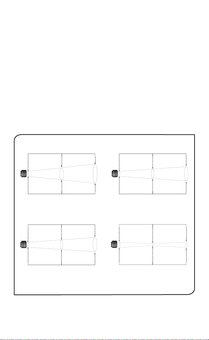
opticaL cHart
The optical chart below indicates the nominal target spot diameter at any given
distance from the sensing head and assumes 90% energy.
4
›
Page 5

inStaLLation
Sensor
BEST
GOOD
INCORREC
Background
Target greater
than spot size
Target equal to
spot size
Target smaller
than spot size
The installation process consists of the following stages:
Preparation
Mechanical installation
Electrical installation
Please read the following sections thoroughly before proceeding with the installation.
preparation
Ensure that the sensor is positioned so that it is focused on the target only.
T
DISTANCE AND SPOT SIZE
The size of the area (spot size) to be measured determines the distance between the
sensor and the target. The spot size must not be larger than the target. The sensor
should be mounted so that the measured spot size is smaller than the target.
REFLECTIONS
The sensor must be installed in a location where energy from lamps, heaters and
sunlight cannot be reflected from the target into the lens. The use of shields may help
in this respect. For further information and assistance contact Omega.
AMBIENT TEMPERATURE
The sensor is designed to operate in ambient temperatures from 0°C to 70°C. For
ambient temperatures above 70°C, an air/water-cooled housing will be required.
Avoid thermal shock. Allow 20 minutes for the unit to adjust to large changes in
ambient temperature.
ATMOSPHERIC QUALITY
Smoke, fumes or dust can contaminate the lens and cause errors in temperature
measurement. In these types of environment the air purge collar should be used to
help keep the lens clean.
›
5
Page 6

ELECTRICAL INTERFERENCE
12.0
45.0
50.0 50.0
40.0
9.0
15.0
25.0 25.0
Ø20.0
60° Rotation 60° Rotation
60° Rotation
9.0
48.0
Fixed Bracket (FBL) Adjustable Bracket (ABL)
2 x Mounting Holes M4 Clearance 2 x Mounting Holes M4 Clearance
9.0
24.024.0
26.0
34.0
47.0 58.5 81.0
1/8 BSP Water/Air Connections
Air Purge Collar
Water/Air Cooling Jacket
To minimise electromagnetic interference or ‘noise’, the sensor should be mounted
away from motors, generators and such like.
WIRING
Check the distance between the sensor and the indicating/controlling device. If
necessary, the OS150 USB 2.2 sensor can be ordered with a longer output cable
attached.
mecHanicaL inStaLLation
All sensors come with a 1 m cable and a mounting nut. The sensor can be mounted
on brackets or cut outs of your own design, or you can use the fixed and adjustable
mounting bracket accessories which are shown below.
AIR/WATER COOLED HOUSING
The air/water cooled housing shown below allows the sensor to withstand high ambient
temperatures. It is equipped with two 1/8” BSP fittings. Water temperature should be 10°C
to 27°C for efficient cooling. Chilled water below 10°C is not recommended. To avoid
condensation, the air purge collar, supplied with the cooled housing, should be used.
6
›
Page 7

1/8 BSP Air connection
27
58.5
26
34
47
AIR PURGE COLLAR
The air purge collar below is used to keep dust, fumes, moisture, and other
contaminants away from the lens. It must be screwed in fully. Air flows into the 1/8”
BSP fitting and out of the front aperture. Air flow should be no more than 5 to 15 litres/
min.
Clean or ‘instrument’ air is recommended.
eLectricaL inStaLLation
The sensor to electronics cable is a 1 m PTFE cable. One end is attached, at the factory,
to the sensor head. The other end has two pairs of wires and a shield (ground) wire.
WIRING
The OS150 USB 2.2 sensor can be used in three different ways as shown below. To
use the analogue output, connect the OS150 USB 2.2 sensor to the controller/indicator with the 24 V DC power supply using the following table and connection diagram
as a guide. The maximum loop impedance is 900 ohms. Note: The OS150 USB 2.2
sensor must be grounded at only one point, either the cable shield or the sensor
housing.
Wire No. Wire Colour Function Tag
1 Red Power supply + PWR +
2 Blue Power supply - PWR –
3 Yellow Signal + OP +
4 Green Signal – OP –
5 Bare Shield ground
Alternatively, to use the USB output, connect the OS150 USB 2.2 sensor to a PC using
the cable provided. No external power supply is required when using the USB output.
The OS150 USB 2.2 sensor can also be used with both the analogue output and USB
connected, provided that the negative terminal of the 24 V DC power supply being
used is not grounded. Note: The OmegaSoft software must be installed before
connecting the sensor to a PC.
›
7
Page 8

omegaSoft Software
+-
-
+
Display/
Controller
Red
Yellow
Green
Blue
Power Supply
-
+
Display/
Controller
PC
PC
N/C
USB
USB
+-
Red
Yellow
Green
Blue
Power Supply
SYSTEM REQUIREMENTS
• OmegaSoft software is designed to run under Windows. Suitable versions are
Windows 2000, Windows XP, Windows Vista and Windows 7.
• The recommended minimum computer specification is:
Intel Pentium processor
VGA display with 640x480 resolution
USB 2.0 port
INSTALLATION
1. Insert the disk provided
2. Installer should run automatically (if not, select the appropriate drive and double click
on Setup.exe)
3. Follow the on-screen instructions
NOTE Do not connect the OS150 USB 2.2 Sensor to the PC before the software is
installed
CONNECTING THE OS150 USB 2.2 SENSOR TO A PC
1. Connect the circular connector on the USB cable provided to the OS150 USB
2.2 sensor
2. Connect the USB A connector on the USB cable provided to an available USB
2.0 port
3. Double click on the OmegaSoft desktop icon
configuration
• Setting Temperature Units
Temperature units can be set on the main temperature panel by pressing °C or °F.
8
›
Page 9

• Setting Output Processing
The temperature range for the analogue output, the averaging period and the peak/
valley hold processing can be set by using the main program menu to select:
[Setup] → [Output Processing]
The temperatures corresponding to the lower and upper limits of the analogue output
can then be set as follows:
Model Lower Limit Upper Limit Minimum Span Maximum Span
LT 45°C 300°C 100°C 255°C
PT 100C 400°C 100°C 300°C
MT 250°C 1000°C 100°C 750°C
HT 450°C 2000°C 100°C 1550°C
The output type can be selected as either 0 mA to 20 mA or 4 mA to 20 mA.
To minimise the the effects of temperature fluctuations, noise etc on the output
signal, the averaging period can be set between 0 and 60 seconds.
If required, Hold Processing can be applied by setting hold mode to Peak Hold or
Valley Hold and setting a hold period between 0 and 1200 seconds.
• Setting Target Emissivity
To set an emissivity value for the OS150 USB 2.2 sensor, use the main program menu
to select:
[Setup] → [Emissivity]
Emissivity can then be set to a value between 0.1 and 1.0, or selected from a pre-
set list of materials by selecting [Data].
MiniMuM Measurable TeMperaTure (OS151-2USB-LT only)
Graph showing the minimum
measuarable object
temperature (T
by surface emissivity (ε) and
), determined
min
sensor temperature (TS).
• Setting Reflected Temperature Compensation
To enable and set reflected temperature compensation, use the main program menu
to select:
[Setup] → [Reflection Compensation]
Reflected temperature compensation can be enabled/disabled using [Compensate
for Reflected Temperature], and when enabled the temperature value can be set
between 45 and 2000°C, depending on the model selected.
To store the changes in the sensor’s memory, select [File] → [Save sensor processing
parameters].
›
9
Page 10

operation
Once the sensor is in position and the appropriate power, air, water, and cable connections are secure, the system is ready for continuous operation by completing the
following simple steps:
1. Turn on the power supply
2. Turn on the instrument or PC
3. Read / monitor the temperature
IMPORTANT
Be aware of the following when using the sensor:
• If the sensor is exposed to significant changes in ambient temperature (hot to cold,
or cold to hot), allow 20 minutes for the temperature to stabilise before taking or
recording measurements.
• Do not operate the sensor near large electromagnetic fields (e.g. around arc welders
or induction heaters) or where energy from lamps, heaters and sunlight could be
reflected into the lens.
Electromagnetic interference can cause measurement errors.
• Wire must be connected only to the appropriate terminals.
maintenance
Our customer service representatives are available for application assistance, calibration, repair, and solutions to specific problems. Contact our Service Department before
returning any equipment. In many cases, problems can be solved over the telephone.
If the sensor is not performing as it should, try to match the symptom below to the
problem. If the table does not help, call Omega for further advice.
TROUBLESHOOTING
Symptom Probable Cause Solution
No output No power to sensor Check power supply
Erroneous temperature Incorrect wire connection Check wire colour codes
Erroneous temperature Faulty sensor cable Verify cable continuity
Erroneous temperature Field of view obstruction Remove obstruction
LENS CLEANING
Keep the lens clean at all times. Any foreign matter on the lens would affect measurement accuracy. Blow off loose particles (if not using the air purge accessory) with an
air ‘puffer’.
Page 11

WARRANTY/ DISCLAIMER
OMEGA ENGINEERING, INC. warrants this unit to be free of defects in materials and
workmanship for a period of 37 months from date of purchase. OMEGA’s WARRANTY
adds an additional one (1) month grace period to the normal three (3) year product
warranty to cover handling and shipping time. This ensures that OMEGA’s customers
receive maximum coverage on each product.
If the unit malfunctions, it must be returned to the factory for evaluation. OMEGA’s
Customer Service Department will issue an Authorized Return (AR) number immediately
upon phone or written request. Upon examination by OMEGA, if the unit is found to be
defective, it will be repaired or replaced at no charge. OMEGA’s WARRANTY does not apply
to defects resulting from any action of the purchaser, including but not limited to
mishandling, improper interfacing, operation outside of design limits, improper repair, or
unauthorized modification. This WARRANTY is VOID if the unit shows evidence of having
been tampered with or shows evidence of having been damaged as a result of excessive
corrosion; or current, heat, moisture or vibration; improper specification; misapplication;
misuse or other operating conditions outside of OMEGA’s control. Components in which
wear is not warranted, include but are not limited to contact points, fuses, and triacs.
OMEGA is pleased to offer suggestions on the use of its various products.
However, OMEGA neither assumes responsibility for any omissions or errors nor
assumes liability for any damages that result from the use of its products in
accordance with information provided by OMEGA, either verbal or written.
OMEGA warrants only that the parts manufactured by the company will be as
specified and free of defects. OMEGA MAKES NO OTHER WARRANTIES OR
REPRESENTATIONS OF ANY KIND WHATSOEVER, EXPRESSED OR IMPLIED,
EXCEPT THAT OF TITLE, AND ALL IMPLIED WARRANTIES INCLUDING ANY
WARRANTY OF MERCHANTABILITY AND FITNESS FOR A PARTICULAR PURPOSE
ARE HEREBY DISCLAIMED. LIMITATION OF LIABILITY: The r emedies of
purchaser set forth herein are exclusive, and the total liability of OMEGA with
respect to this order, whether b ased on contract, w arranty, negligence,
indemnification, strict liability or otherwise, shall not exceed the purchase price
of the component upon which liability is based. In no event shall OMEGA be
liable for consequential, incidental or special damages.
CONDITIONS: Equipment sold by OMEGA is not intended to be used, nor shall it be used:
(1) as a “Basic Component” under 10 CFR 21 (NRC), used in or with any nuclear installation
or activity; or (2) in medical applications or used on humans. Should any Product(s) be used
in or with any nuclear installation or activity, medical application, used on humans,
misused in any way, OMEGA assumes no responsibility as set forth in our basic
WARRANTY / DISCLAIMER language, and, additionally, purchaser will indemnify OMEGA
and hold OMEGA harmless from any liability or damage whatsoever arising out of the use
of the Product(s) in such a manner.
or
Direct all warranty and repair requests/inquiries to the OMEGA Customer Service
RETURN REQUESTS/INQUIRIES
Department. BEFORE RETURNING ANY PRODUCT(S) TO OMEGA, PURCHASER MUST
OBTAIN AN AUTHORIZED RETURN (AR) NUMBER FROM OMEGA’S CUSTOMER SERVICE
DEPARTMENT (IN ORDER TO AVOID PROCESSING DELAYS). The assigned AR number
should then be marked on the outside of the return package and on any correspondence.
The purchaser is responsible for shipping charges, freight, insurance and proper packaging
to prevent breakage in transit.
FOR WARRANTY
have the following information
available BEFORE contacting OMEGA:
1. Purchase Order number under which
the product was PURCHASED,
2. Model and serial number of the
product under warranty, and
3. Repair instructions and/or specific
problems relative to the product.
OMEGA’s policy is to make running changes, not model changes, whenever an improvement is possible.
This affords our customers the latest in technology and engineering.
OMEGA is a registered trademark of OMEGA ENGINEERING, INC.
© Copyright 2011 OMEGA ENGINEERING, INC. All rights reserved. This document may not be copied, pho-
tocopied, reproduced, translated, or reduced to any electronic medium or machine-readable form, in whole
or in part, without the prior written consent of OMEGA ENGINEERING, INC.
RETURNS, please
FOR NON-WARRANTY REPAIRS,
for current repair charges. Have the following
information available BEFORE contacting OMEGA:
1. Purchase Order number to cover the
COST of the repair,
2. Model and serial number of the
product, and
3. Repair instructions and/or specific problems
relative to the product.
consult OMEGA
Page 12

Where Do I Find Everything I Need for
Process Measurement and Control?
OMEGA…Of Course!
Shop online at omega.com
TEMPERATURE
Thermocouple, RTD & Thermistor Probes, Connectors, Panels & Assemblies
Wire: Thermocouple, RTD & Thermistor
Calibrators & Ice Point References
Recorders, Controllers & Process Monitors
Infrared Pyrometers
PRESSURE, STRAIN AND FORCE
Transducers & Strain Gages
Load Cells & Pressure Gages
Displacement Transducers
Instrumentation & Accessories
FLOW/LEVEL
Rotameters, Gas Mass Flowmeters & Flow Computers
Air Velocity Indicators
Turbine/Paddlewheel Systems
Totalizers & Batch Controllers
pH/CONDUCTIVITY
pH Electrodes, Testers & Accessories
Benchtop/Laboratory Meters
Controllers, Calibrators, Simulators & Pumps
Industrial pH & Conductivity Equipment
DATA ACQUISITION
Data Acquisition & Engineering Software
Communications-Based Acquisition Systems
Plug-in Cards for Apple, IBM & Compatibles
Data Logging Systems
Recorders, Printers & Plotters
HEATERS
Heating Cable
Cartridge & Strip Heaters
Immersion & Band Heaters
Flexible Heaters
Laboratory Heaters
ENVIRONMENTAL
MONITORING AND CONTROL
Metering & Control Instrumentation
Refractometers
Pumps & Tubing
Air, Soil & Water Monitors
Industrial Water & Wastewater Treatment
pH, Conductivity & Dissolved Oxygen Instruments
SM
M5069/1211
 Loading...