

Omega Products OS100-MB Installation Manual
OS100 SERIES
Mini-Infrared Transmitter
MADE IN
omega.com
e-mail: info@omega.com
For latest product manuals:
omegamanual.info
User’s Guide
Shop online at
OS101
OS102

Servicing North America:
U.S.A.: One Omega Drive, P.O. Box 4047
ISO 9001 Certified Stamford, CT 06907-0047
TEL: (203) 359-1660
FAX: (203) 359-7700
e-mail: info@omega.com
Canada: 976 Bergar
Laval (Quebec) H7L 5A1, Canada
TEL: (514) 856-6928
FAX: (514) 856-6886
e-mail: info@omega.ca
For immediate technical or application assistance:
U.S.A. and Canada: Sales Service: 1-800-826-6342/1-800-TC-OMEGA
®
Customer Service: 1-800-622-2378/1-800-622-BEST
®
Engineering Service: 1-800-872-9436/1-800-USA-WHEN
®
Mexico: En Espan˜ ol: (001) 203-359-7803
e-mail: espanol@omega.com
FAX: (001) 203-359-7807
info@omega.com.mx
Servicing Europe:
Czech Republic: Frystatska 184, 733 01 Karviná, Czech Republic
TEL: +420 (0)59 6311899
FAX: +420 (0)59 6311114
Toll Free: 0800-1-66342
e-mail: info@omegashop.cz
Germany/Austria: Daimlerstrasse 26, D-75392 Deckenpfronn, Germany
TEL: +49 (0)7056 9398-0
FAX: +49 (0)7056 9398-29
Toll Free in Germany: 0800 639 7678
e-mail: info@omega.de
United Kingdom: One Omega Drive, River Bend Technology Centre
ISO 9002 Certified Northbank, Irlam, Manchester
M44 5BD United Kingdom
TEL: +44 (0)161 777 6611
FAX: +44 (0)161 777 6622
Toll Free in United Kingdom: 0800-488-488
e-mail: sales@omega.co.uk
OMEGAnet®Online Service Internet e-mail
omega.com info@omega.com
It is the policy of OMEGA Engineering, Inc. to comply with all worldwide safety and EMC/EMI
regulations that apply. OMEGA is constantly pursuing certification of its products to the European New
Approach Directives. OMEGA will add the CE mark to every appropriate device upon certification.
The information contained in this document is believed to be correct, but OMEGA accepts no liability for any
errors it contains, and reserves the right to alter specifications without notice.
WARNING: These products are not designed for use in, and should not be used for, human applications.

i
Table of Contents
Section ................................................................... Page
Safety Warnings and IEC Symbols ............................. iii
Caution and Safety Information .................................. iii
Section 1 Introduction .................................................................... 1-1
Section 2 Installation ...................................................................... 1-1
2.1 Unpacking and Inspection ...................................... 1-1
2.2 Electrical Connection .............................................. 2-1
Section 3 Operation ........................................................................ 3-1
3.1 Main Board ................................................................ 3-1
3.2 Ambient Temperature .............................................. 3-2
3.3 Atmospheric Quality ................................................ 3-3
3.4 Measuring Temperature .......................................... 3-3
3.5 Alarm Setting ............................................................ 3-4
3.6 Adding Extension Cable........................................... 3-4
Section 4 Laser Sight Accessory ................................................... 4-1
4.1 Warning and Cautions ............................................. 4-1
4.2 Operating the Laser Sight Accessory ..................... 4-1
Section 5 Specifications ................................................................. 5-1
5.1 General ....................................................................... 5-1
5.2 Laser Sight Accessory (OS100-LS) .......................... 5-2
Section 6 Emissivity Table ............................................................. 6-1
OS100 Series Infrared Transmitter
Table of
Contents

ii
Table of Figures
Figure Description Page
2-1 Power Supply & Analog Output Connections .......... 2-1
2-2 Alarm Output Connection ............................................ 2-1
3-1 Main PC Board ............................................................... 3-2
3-2 Sensor Housing .............................................................. 3-2
3-3 Optical Field of View ..................................................... 3-4
3-4 Setting the Temperature Engineering Unit.................. 3-4
3-5 Mounting Bracket OS100-MB ....................................... 3-5
3-6 Water Cooling Jacket, OS100-WC ................................ 3-5
3-7 Typical Water Cool Jacket Assembly ........................... 3-5
3-8 Air Purge Collar, OS100-AP .......................................... 3-6
3-9 DIN Rail Mounting Adapter, OS100-DR .................... 3-6
3-10 NEMA-4 Aluminum Enclosure .................................... 3-6
4-1 Laser Sighting Accessory, OS100-LS ............................ 4-2
4-2 Laser Warning Label ...................................................... 4-2
OS100 Series Infrared Transmitter
Table of
Figures
Safety Warnings and IEC Symbols
This device is marked with international safety and hazard symbols in
accordance with IEC 1010. It is important to read and follow all precautions and
instructions in this manual before operating or commissioning this device as it
contains important information relating to safety and EMC. Failure to follow all
safety precautions may result in injury and or damage to your calibrator.
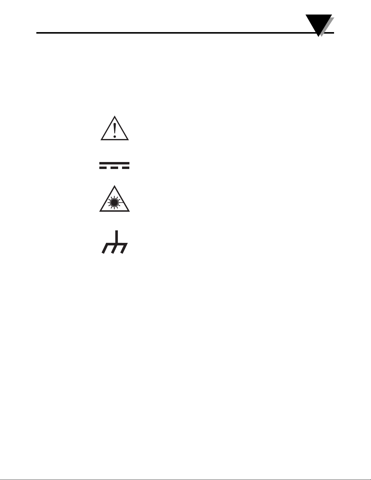
IEC symbols Description
Caution and Safety Information
• If the equipment is used in a manner not specified in this manual, the
protection provided by the equipment may be impaired.
• The installation category is one (1).
• There are no user replaceable fuses in this product
• The output terminals of this product are for use with equipment (digital
meters, chart recorders, etc,) which have no accessible five parts. Such
equipment should comply with all the applicable safety requirements.
• Do not operate the equipment in flammable or explosive environments.
• All connections to the thermometer should be made via a shielded
cable, 24 AWG stranded wire with the following ratings: 300V, 105°C
(221°F), PVC insulation.
• Power must be disconnected before making any electrical connections.
• The power supply used to power the thermometer should be VDE or
UL approved with the following ratings: 12 to 24vdc @150mA with
overload protection of 500mA.
OS100 Series
iii
Caution, refer to accompanying
documents
Direct Current
Laser Symbol
Frame or Chassis

NOTES:
OS100 Series
iv

Section 1 - Introduction
The low cost OS101 mini-infrared transmitter provides non-contact
temperature measurement for industrial applications. The unit measures a
temperature range of -18 to 538°C (0-1000°F) and provides a linear analog
output of either 4-20 mA, 0-5 VDC, K type TC, 1 mV/°C, or 1 mV/°F.
The new OS102 mini-infrared transmitter has all the functions of OS101
plus a built-in LED display that shows the measured temperature in
degrees F or degrees C which is switchable in the field.
The miniature sensor head design 2.5 cm dia. x 6.3 cm Length (1" x 2.5") is
ideal for measuring temperature in confined, and hard to reach places.
The aluminum sensor head as well as the rugged electronic housing (Die
cast Aluminum) are NEMA-4 rated.
The sensor head is connected to the electronic housing via a 1.82 m (6 feet)
shielded cable as standard. The unit provides field adjustable alarm
output.
Section 2 - Installation
2.1 Unpacking
Remove the packing list and verify that you have received all your
equipment. If you have any questions about the shipment, please call
Customer Service at:
1-800-622-2378 or 203-359-1660. We can also be reached on the internet:
omega.com e-mail: info@omega.com
When you receive the shipment, inspect the container and equipment for
any signs of damage. Note any evidence of rough handling in transit.
Immediately report any damage to the shipping agent.
The carrier will not honor any damage claims unless all the shipping materials are saved for
inspection. After examination and removing contents, save packing material and carton in the
event reshipment is necessary.
The following items are supplied in the box:
• The infrared transmitter including the sensor head and the 1.82 m
(6 feet) shielded cable
• User's Manual
• Mounting Nut
OS100 Series - Introduction
1
1-1
NOTE:
OS100 Series - Installation
2
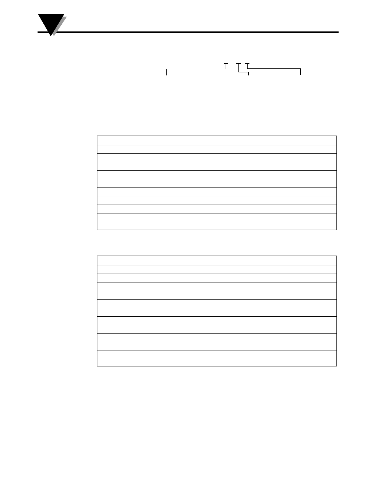
The following describes the ordering information:
OS102 or OS101 - MA - *, **, where
The following optional accessories are available:
Here are the Features of OS101 and OS102 infrared transmitters:
2.2 Electrical Connection
Sensor Head Cable - The Sensor head is pre-wired to a 1.8 m (6 feet)
shielded cable. Plug & lock-in the male connector to the mating female
connector on the aluminum housing.
Power & Output Connection - Open the cover of the main aluminum
housing. Slide the cable through the strain relief and connect the wires to
the terminal block on the board as shown in Fig. 2-1. For Alarm output
connection, refer to Fig. 2-2.
2-1
Model No. Description
OS100-MB Mounting Bracket
OS100-DR DIN Rail Mounting adapter
OS100-WC Water Cooling jacket
OS100-AP Air purge collar
OS100-LS Laser Sighting
OS100-CA15FT Sensor Head Extension Cable (4.6 m, 15")
OS100-CA25FT Sensor Head Extension Cable (7.6 m, 25')
TX8-100 8 Conductor stranded Shielded cable (30 m, 100')
PSU-93 Unregulated 16-24 VDC Power Supply
CAL3-IR NIST Traceable Calibration
Features OS101 OS102
Accuracy 2% Rdg or 4°F (2.2°C)
Temp Range 0-1000°F (-18 to 538°C)
Emissivity 0.1 to 0.99 Adj.
Field of View 6 to 1
Alarm Output Standard
1mV/Deg. Output Standard
4-20mA Output Standard
0/5 VDC Output Standard
K Type T/C Std. ––
LED Display –– Std.
Main Housing 65.5 x 30.5 x 115.3 mm 65.5 x 55.9 x 115.3 mm
(2.58" x 1.2" x 4.54") 2.58" x 2.2" x 4.54"
MA - 4/20 mA output
V1 - 0 to 5 VDC output
K - Thermocouple output, K type
MV - Millivolt output
C - 1 mV/°C output
F - 1 mV/°F output
HT- High
temperature
sensor head
 Loading...