

Page 1

Table of Contents
Part 1 Introduction
1.1 General 5
1.2 System Features 7
1.3 Instrument Specifications 9
1.4 Performance Specifications 12
Part 2 Mounting
2.1 General Mounting 13
2.2 Wall Mounting 14
2.3 Pipe Mounting 14
2.4 DIN Rail Mounting 16
2.5 Integral Mounting 16
2.6 Panel Mounting 16
Part 3 Electrical Installation
3.1 General 20
3.2 Two-Wire Configuration 20
3.21 Load Drive Capability
22
3.3 115/230 VAC Configuration 23
3.4 115/230 VAC w/ 2 Relays Configuration 25
3.5 Battery-Powered Configuration 27
Part 4 Sensor Connection
4.1 General 31
4.2 ORE-45P Sensor Connection 32
4.3 Combination Electrode Connection 33
4.4 External Temperature Compensators 34
4.5 Long Cable Length Issues 35
Part 5 Operation
5.1 User Interface 38
5.11 Keys
5.12 Display
5.2 Software 41
5.22 Default Menu
5.23 Calibration Menu
5.24 Configuration Menu
5.25 Diagnostics Menu
5.21 Software Navigation
39
39
41
44
45
46
54
Rev. B, 05/02
ORTX-45
2
Page 2

Table of Contents (continued)
Part 6 Calibration
6.1 Overview and Methods 59
6.11 Sensor Slope
6.12 Sensor Offset
6.14 1-Point Calibration Explained
6.13 2-Point Calibration Explained
60
60
61
61
6.2 Performing a 2-Point Calibration 62
6.3 Performing a 1-Point Calibration 64
6.4 Temperature Calibration 66
6.5 TC Factor Calibration 67
Part 7 Service and Maintenance
69
7.1 System Checks 71
7.2 Instrument Checks 72
7.3 Display Messages 73
Rev. B, 05/02
ORTX-45
3
Page 3

Table of Contents (continued)
Diagrams and Illustrations
Figure 1-1
Figure 1-2 Specifications - Views 11
Figure 2-1 Multi-Purpose Bracket 15
Figure 2-2 ORTX-45 Mounting Configurations 15
Figure 2-3
Figure 2-4
Figure 2-5 115/230 VAC Panel Mount and Cut-out 19
Figure 3-1 Loop Power Connection 21
Figure 3-2 Line Power Connection 24
Figure 3-3
Figure 3-4
Figure 3-5 Relay Contacts 27
Figure 3-6 DC Battery Board Connection 28
Figure 4-1 Bulkhead Connection 31
Figure 4-2
Figure 4-3
Combination Electrode 33
Figure 4-4 External Temperature Compensators 34
Figure 4-5
Three-Wire RTD Connection 37
Figure 5-1
Figure 5-2 Software Map 43
Figure 5-3 Control Relay Example 49
Figure 5-4
Figure 7-1 ORTX-45 Assembly Diagram 69
Figure 7-2
ORTX-45 Configurations 6
2-Wire Integral Mount Detail 17
2-Wire Panel Mount and Cut-out 17
Line Power w/ Relays Connection 26
Relay Cable Connection 26
Sensor Cable Connections, ORE-45P 32
Sensor Cable Connections,
Junction Box Connection and
User Interface 38
Alarm Relay Example 50
ORTX-45 Assembly, optional 70
Rev. B, 05/02
ORTX-45
4
Page 4

Part 1 - Introduction
1.1 General
The Model ORTX-45 ORP monitor/analyzer provides an
extremely versatile measurement system for monitoring
and control of ORP (oxidation/reduction potential, also
known as REDOX) over the range of –1000 mV to +2000
mV. The instrument is offered standard as a looppowered transmitter for 2-wire DC applications. Since this
system configuration operates over only two low-voltage
wires, it is ideal for remote monitoring applications where
line power is either unavailable or prohibitively expensive
to run.
With an optional plug-in card, the instrument may also be
configured for 115/230 VAC operation. This configuration
is ideal when line power is located close to the point of
installation, and only a single isolated 4-20 mA output is
required.
An optional plug-in card is also available that provides
dual relay output, and two 4-20 mA outputs (one for ORP
and one for temperature) to convert the instrument to an
ORP controller. This card must be used with the 115/230
VAC option. This option expands the output capability of
the controller for applications that require relay-setpoint
functionality.
Note:
Rev. B, 05/02
An optional plug-in card is available that converts the
instrument into a robust, view-only, portable measurement system that operates on one 9 VDC battery. In this
configuration, all of the standard features of the basic 2wire transmitter are functional with the exception that the
instrument does not output a 4-20 mA current. Since this
system utilizes the same high performance ORE-45P
sensor as the standard configurations, it is a very robust
portable monitoring system. It can be used on its own, or
it can be used with other permanently installed ORTX-45
continuous monitoring systems to simplify calibration by
using the calibrate-by-reference method.
Due to the high-degree of flexibility of the **TX-45 system
options, it is important to note areas of the operating
manual that detail these optional features. The software
features for the relay output option and battery option only
appear when those modules are connected and the
system has been re-powered.
ORTX-45
5
Page 5
Part 1 - Introduction 1.1 General
In all configurations, the ORTX-45 displays mV, sensor
temperature, and output loop current on the secondary
line of the custom display. The instrument may be used
directly with either the high performance Quantum series
of sensors or with standard combination-style electrodes.
The Model ORTX-45 offers maximum mounting flexibility.
A bracket is included with each unit that allows mounting
to walls, pipes, panels, or DIN rail. In addition, the system
is designed to be integral mounted. Integral mounting is
an ideal solution for tight spaces where no mounting exists
except for atop the sensor.
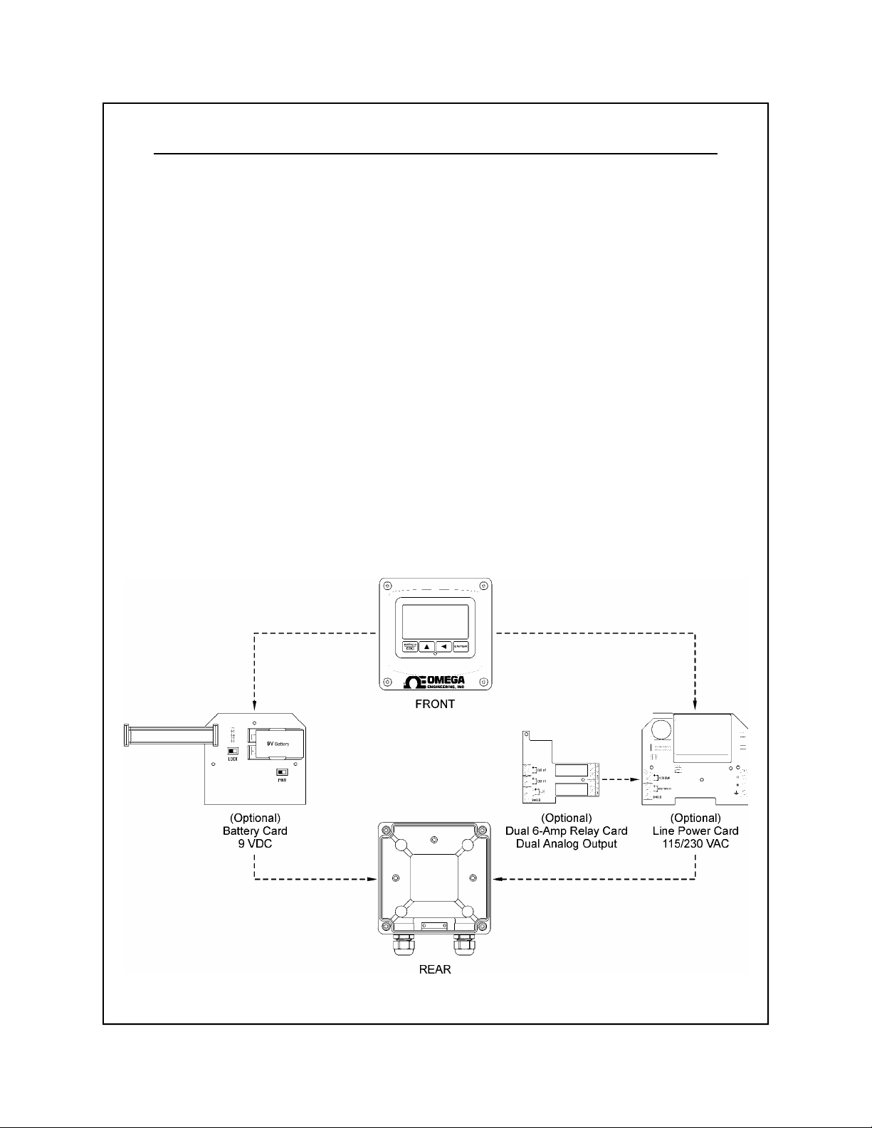
Figure 1-1 illustrates the configuration possibilities for the
ORTX-45 monitor/analyzer system. At any time, options
can be added or removed from the standard unit. The
system software automatically recognizes the options on
power-up and properly enables those new features. This
allows the basic 2-wire module to be stocked as a spare
part for any of the measurement systems.
Rev. B, 05/02
Figure 1-1 ORTX-45 Configurations
ORTX-45
6
Page 6

Part 1 - Introduction 1.2 System Features
1.2 System Features
•
Standard main module is designed to be a fully isolated,
loop powered instrument for 2-wire DC applications.
Protected from surge and brownout. Optional integral
power supply card for 115/230 VAC operation, and
optional battery power supply card for portable applications are available.
• Output Hold, Output Simulate, Output Alarm, and
Output Delay Functions. All forced changes in output
condition include bumpless transfer to provide gradual
return to on-line signal levels and to avoid system
control shocks on the main analog output (ORP).
• Optional plug-card provides dual SPDT relay operation.
Software settings for relay control mode include setpoint, deadband, phase, delay, and failsafe. Software
controls automatically appear in menu list when
hardware option card is plugged in and system power
is applied.
•
Selectable HI-LO alarm “band” mode feature on Relay
A. This feature allows the User to select two set points
on the same relay, so that a high and low limit alarm
can be established on one set of contacts.
•
Selectable Output Fail Alarm feature allows system
diagnostic failures to be sent to external monitoring
systems.
• Selectable Probe Timer feature on Relay B allows
connection of probe cleaner hardware or other accessories that require timed periodic relay contacts.
• Large, high contrast, custom Super-Twist display
provides excellent readability even in low light conditions.
The secondary line of display utilizes 5×7 dot matrix
characters for clear display of messages, avoiding
cryptic segmented character messages. Two of four
measured parameters may be on the display simultaneously.
Rev. B, 05/02
ORTX-45
7
Page 7

Part 1 - Introduction 1.2 System Features
•
Sensor diagnostics monitor glass breakage, sensor
leaks, and RTD condition. Diagnostic messages
provide a clear description of any problem with no
confusing error codes to look up. Messages are also
included for diagnosing calibration problems.
• Flexible two-point and sample calibration methods.
To provide high accuracy, all calibration methods include stability monitors that check temperature and main
parameter stability before accepting data.
• Selectable Pt1000 or Pt100 temperature inputs.
Systems can also be hard-configured for three-wire
elements. Temperature element can be user calibrated.
• Security lock feature to prevent unauthorized tampering
with instrument settings. All settings can be viewed while
locked, but they cannot be changed.
High reliability, microprocessor based system with
•
non-volatile memory back-up that utilizes no batteries.
Low mass, surface mount PCB construction containing
no user adjustment potentiometers. All factory calibrations stored in non-volatile EEPROM.
Rev. B, 05/02
ORTX-45
8
Page 8

Part 1 - Introduction 1.3 Instrument Specifications
1.3 Instrument Specifications, ORTX-45 (common to all variations)
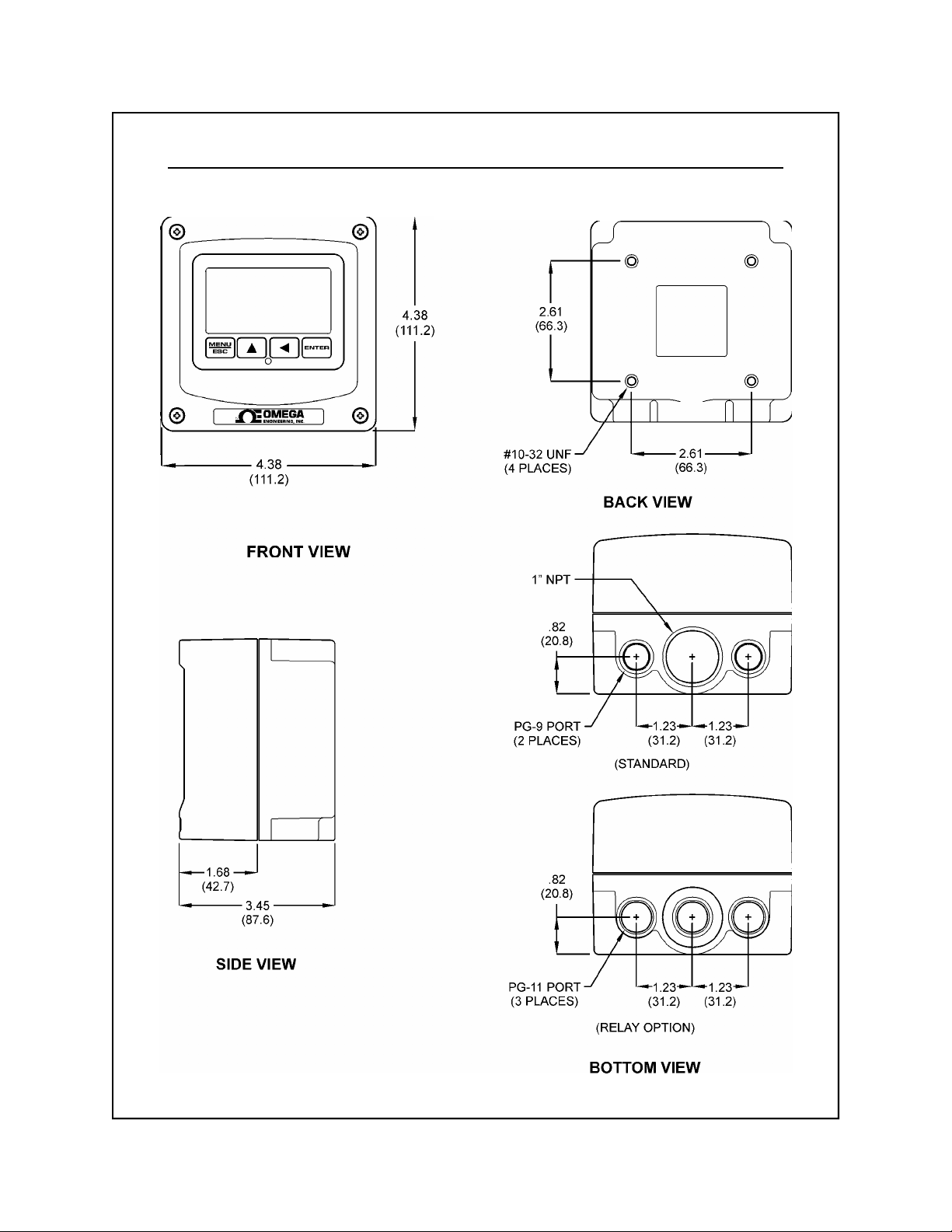
Enclosure
NEMA 4X, IP66, polycarbonate, stainless steel hardware,
weatherproof and corrosion resistant,
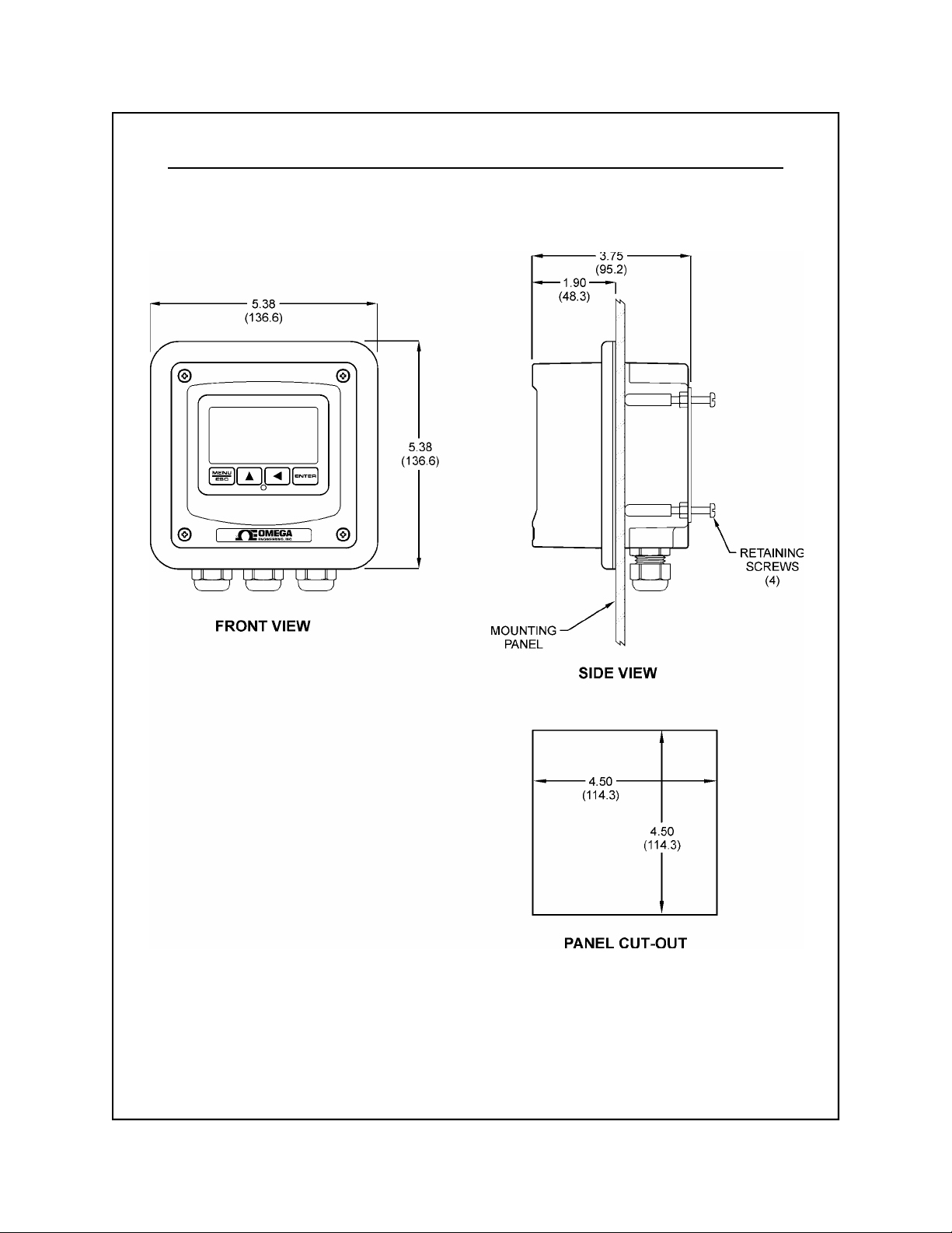
HWD: 4.4" (112 mm) × 4.4" (112 mm) × 3.5" (89 mm)
Mounting Options Wall, panel, pipe, DIN rail, or integral-sensor (DC only)
Conduit Openings
Standard: 2 - PG-9 openings, 1 - 1" NPT center opening,
cordgrips and plug included.
Relay option: 3 - PG-11 openings, plugs included
Weight
DC transmitter configuration: 1 lb. (0.45 kg)
Line-powered unit: 1.5 lb. (0.68 kg)
Display
Large, high-contrast, Super-Twist (STN) LCD;
4-digit main display with sign, 0.75" (19.1 mm) seven-
segment characters;
12-digit secondary display, 0.3" (7.6 mm) 5×7 dot
matrix characters
Keypad 4-key membrane type with tactile feedback, polycar-
bonate with UV coating, integral EMI/static shield and
conductively coated window
Ambient Temperature Service, -20 to 60 °C (-4 to 140 ºF)
Storage, -30 to 70 °C (-22 to 158 ºF)
Ambient Humidity 0 to 95%, non-condensing
Location
EMI/RFI Influence
Designed for hazardous and non-hazardous areas
Designed to EN 61326-1
Output Isolation 600 V galvanic isolation
Filter Adjustable 0-9.9 minutes additional damping to 90%
step input
Temperature Input Selectable Pt1000 or Pt100 RTD with automatic
compensation
Rev. B, 05/02
ORTX-45
9
Page 9

Part 1 - Introduction 1.3 Instrument Specifications
Instrument Specifications, ORTX-45 (NOT common to all variations)
»Basic 2-Wire Transmitter:
Power
DC Cable Max. Length
DC Cable Type
Insertion Loss 15.5 VDC
16-35 VDC (2-wire device)
3000 feet (914 meters)
Belden twisted-pair, shielded
»115/230 VAC Option:
Power
4 kV line isolation
Fuse
115/230 VAC ± 10%, 50/60 Hz
250 mA slow-blo on hot line, auto-reset secondary
»115/230 VAC Option + Dual Relays Option:
Power
Fuse
Relays Electromechanical:
Dual SPDT, 6 amp @ 250 VAC, 5 amp @ 24 VDC contacts.
Dual SPST (N.O.) 0.06-2.0 Amp @12-280 VAC, RMS
Dual SPST (N.O.) 3 Amp @ 60 VDC
Software selection for setpoint, phase, delay, deadband,
Analog Outputs
115/230 VAC ± 10%, 50/60 Hz
250 mA slow-blo on hot line, auto-reset secondary
Solid State (AC):
Solid State (DC):
hi-lo alarm, and failsafe. A-B indicators on main LCD.
Dual 4-20 mA current loops, one for main parameter and
one for temperature. Max load 500 Ohms on main and 500
Ohms on temperature.
»Battery Option:
Power
Auto-OFF Time
Low Battery Indication
Battery Life Normal Use (2-4 hours per week), 4-6 months
Continuous operation, 10-14 days
Rev. B, 05/02
Generic 9 VDC alkaline battery
2 hours after no keypress
6.75 VDC
ORTX-45
10
Page 10
Part 1 - Introduction 1.3 Instrument Specifications
Inches (mm)
Rev. B, 05/02
Figure 1-2 Specifications - Views
ORTX-45
11
Page 11

Part 1 - Introduction 1.4 Performance Specifications
1.4 Performance Specifications, ORTX-45
(common to all variations)
Displayed Parameters
Main input, -1000 to +2000 mV
Loop current, 4.00 to 20.00 mA
Sensor temperature, -10.0 to 110.0 °C (14 to 230 ºF)
Main Parameter Range -1000 mV to +2000 mV
Input Impedance
Repeatability
Sensitivity
0.1% of span or better
0.05% of span
Greater than 10
13
Ohms
Non-linearity 0.1% of span
Stability 0.05% of span per 24 hours, non-cumulative
Temperature Drift Span or zero, 0.02% of span/°C
Warm-up Time
Instrument Response Time
7 seconds to rated performance
6 seconds to 90% of step input at lowest setting
Max. Sensor-Instrument
Distance
3000 ft. (914 meters) w/ preamp,
30 ft. (9.1 meters) w/o preamp
Sensor Types Omega ORP w/ preamp, 5 wire input (Model ORE-45P),
or combination style ORP electrode w/ TC - 2 wire input
Rev. B, 05/02
ORTX-45
12
Page 12

Part 2 - Mounting
2.1 General
All **TX-45 Series Instruments offer maximum mounting
flexibility. A bracket is included with each unit that allows
mounting to walls, pipes and DIN rail. In all cases, choose
a location that is readily accessible for calibrations. Also
consider that it may be necessary to utilize a location
where solutions can be used during the calibration process.
To take full advantage of the high contrast display, mount
the instrument in a location where the display can be
viewed from various angles and long distances.
The two-wire version of the instrument is ideal for remote
mounting applications where line power in unavailable and
expensive to run, or in locations where only low-voltage
wiring is allowed. The 115/230 VAC powered version of
the instrument is designed to be used where line power is
already available. The portable version can be used for
survey measurements or for calibration checks of a larger
number of permanently installed units.
Locate the instrument in close proximity to the point of
sensor installation - this will allow easy access during
calibration. Sensor-to-instrument distances of over 3000
feet are possible with the high performance Omega
ORE-45P sensor, but this is not generally recommended
since it may hamper access to sensor during calibration.
The sensor-to-instrument distance for combination style
electrodes must not exceed 30 feet.
Rev. B, 05/02
For long distance installations (50 feet or more), standard
sensor cable (10 feet) in combination with a junction box
and interconnect cable is recommended. Sensors with
extremely long cables can be cumbersome to remove for
cleaning or service. It is much more convenient to remove
or replace a sensor with only 10 feet of cable when a
junction box is used. It is also far more economical.
In general, the location should be relatively dry and clean
with little or no vibration, and the ambient temperature
must be within the operating temperature limits of the
instrument. Avoid areas where the instrument may be
frequently splashed with corrosive process materials.
Particularly in the integral mount version, excessive vibration
or heat from the process line may degrade the reliability of
the system.
ORTX-45
13
Page 13

Part 2 - Mounting 2.1 General
Note: Never leave the instrument case open for ex-
tended periods of time. This can allow corrosive
materials to attack the circuitry of the system.
Due to the high flexibility of the instrument design, some of
the mounting features change based on the option boards
that may be installed. For example, the panel mounting
implementation is different for the 115/230 VAC controller
because the rear of the enclosure must be used. A
special flange must be used to seal the entire enclosure
to the panel. In the 2-wire transmitter configuration, just
the front of the enclosure can be mounted. In addition, the
115/230 VAC must not be integral mounted. Carefully
study all mounting configurations.
2.2 Wall
Mounting
2.3 Pipe
Mounting
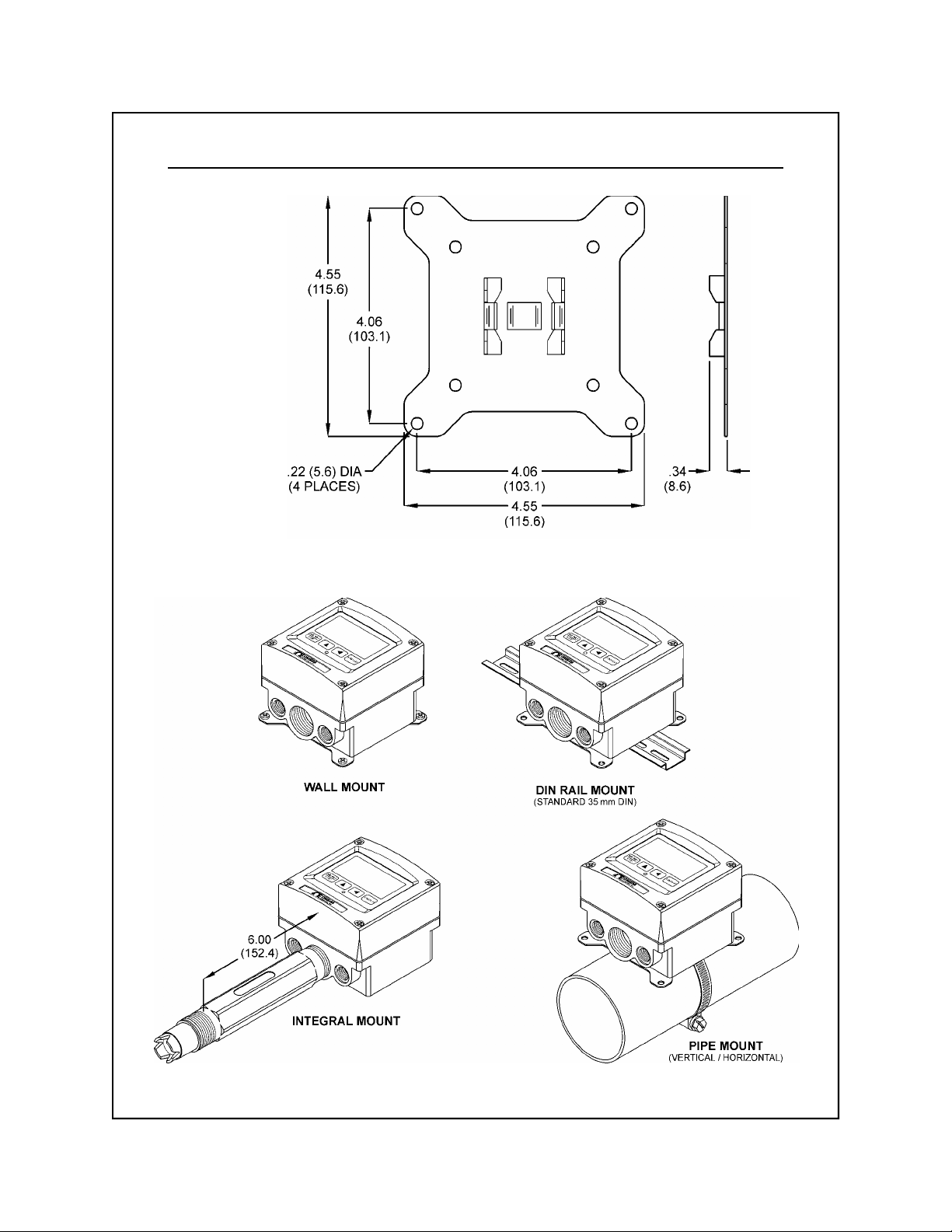
Any of the instrument configurations may be wall mounted
(see Figures 2-1 and 2-2 for details). The multi-purpose
bracket is attached to the rear of the enclosure using the
four provided pan head screws. The protrusion side of the
multi-purpose bracket should face into the depression on
the rear of the instrument enclosure. The instrument is
then attached to the wall using the four outer mounting
holes in the bracket.
For the pipe mounting configuration, the multipurpose
bracket is attached to the rear of the enclosure with the
four provided screws. The protrusion on the bracket must
face outward. The bracket may be rotated for proper
alignment prior to mounting (see Figures 2-1 and 2-2 for
details).
Once the bracket is fastened to the rear of the enclosure, the
provided pipe clamp must be completely opened and slipped
through the two slots in the multi-purpose mounting bracket.
The clamp is then looped around the pipe, re-attached, and
tightened.
Rev. B, 05/02
ORTX-45
14
Page 14
Part 2 - Mounting 2.3 Pipe Mounting
Inches (mm)
Figure 2-1 Multi-Purpose Bracket
Rev. B, 05/02
Figure 2-2 ORTX-45 Mounting Configurations
ORTX-45
15
Page 15

Part 2 - Mounting 2.4 DIN Rail Mounting
2.4 DIN Rail
Mounting
2.5 Integral
Mounting
For the DIN rail mounting configuration, the multipurpose
bracket is attached to the rear of the enclosure with the
four provided screws. The protrusion on the bracket must
face outward. The bracket may be rotated for proper
alignment prior to mounting (see Figures 2-1 and 2-2 for
details).
Once the bracket is fastened to the rear of the enclosure,
the unit must be slid onto the DIN rail. It does not lock into
place. Therefore, if the unit is removed for service or
replacement, it must be slid off of the DIN rail, or the front
half of the controller can be removed and replaced since
all of the electronics in the 2-wire configuration reside in
the front half.
Only the 2-wire configuration may be mounted directly on
the back of the Model ORE-45P sensor (see Figures 2-2
and 2-3 for details).
Note: Do not attempt to integral mount the 115/230
VAC configuration. This configuration is not
designed to be mounted directly to the sensor.
2.6 Panel
Mounting
Rev. B, 05/02
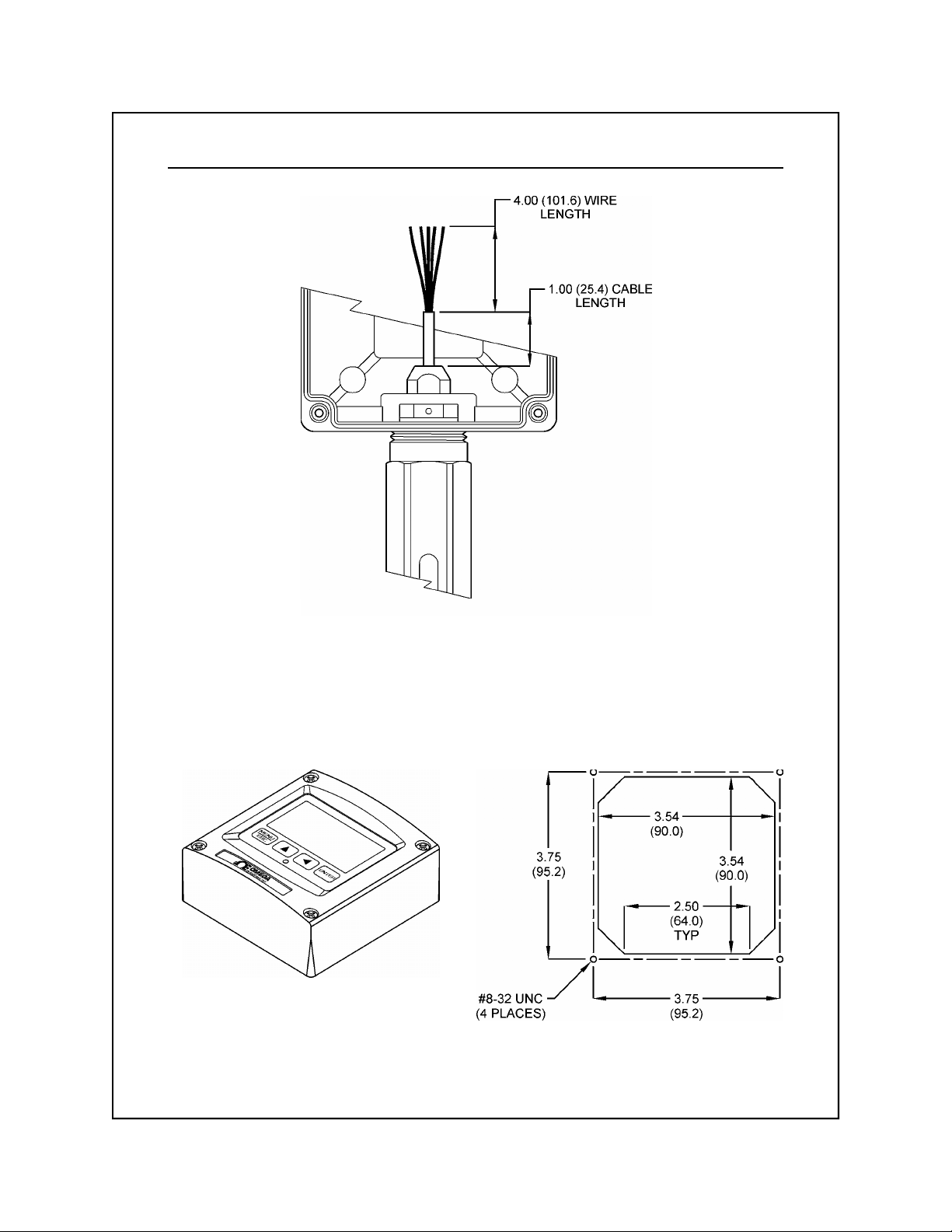
For an integral mount connection, the sensor cable must
be cut substantially to fit into the instrument enclosure.
Cut and strip the sensor cable as shown in Figure 2-3.
Screw the sensor fully into the enclosure base before
completing wiring connections.
The instrument may also be panel mounted in two different
ways:
In the 2-wire configuration, the front half of the enclosure
may be separated and mounted by itself, as shown in
Figure 2-4. Note that the rear of the instrument enclosure
is not utilized in this mounting scheme. Holes must be
drilled at the perimeter of the panel cut-out that allow the
enclosure screws to pass through and be retained on the
back side. User-supplied #8-32 nuts are used to fasten
the instrument from the back. The FIP instrument gasket
remains intact during this mount to seal to the panel.
ORTX-45
16
Page 16
Part 2 - Mounting 2.6 Panel Mounting
Inches (mm)
Inches (mm)
Figure 2-3 2-Wire Integral Mount Detail
Figure 2-4 2-Wire Panel Mount and Cut-out
Rev. B, 05/02
ORTX-45
17
Page 17

Part 2 - Mounting 2.6 Panel Mounting
In the full enclosure configuration (necessary with the
115/230 VAC card option), the entire enclosure is panelmounted using a special optional sealing flange.
The sealing flange must first be attached to the enclosure.
Remove the enclosure hinge by bending one of the hinge
legs inward toward the center of the enclosure with a
pair of needle nose pliers. Once it is loose, slide the
hinge leg out the opposite side. When completed, remove
the two hinge retainer screws and hinge plate assembly.
Fasten the flange to the rear half of the enclosure using
the four hex retainers. The flange gasket material must
face towards the rear of the enclosure. Re-install the
hinge and hinge plate assembly onto the flange using the
two hinge screws. Re-attach hinge pins to the front half of
the enclosure by bending the hinge pin leg with a pair of
needle nose pliers. The flange is now installed. Seal up
the finished enclosure by tightening down the four enclosure
screws prior to mounting.
A different cut-out is required for this configuration, as
shown in Figure 2-5. Once the cut-out has been completed,
insert the flanged enclosure through the cut-out. The
mounting bracket is then attached to the rear of the enclosure
as shown. Install the four tension screws through the four
mounting holes in the bracket, and place the no-slip
rubber boots on each screw. Tighten all screws down to
seal the enclosure flange onto the panel.
Rev. B, 05/02
ORTX-45
18
Page 18
Part 2 - Mounting 2.6 Panel Mounting
Inches (mm)
Rev. B, 05/02
Figure 2-5 115/230 VAC Panel Mount and Cut-out
ORTX-45
19
Page 19

Part 3 - Electrical Installation
3.1 General
The instrument may be powered in several ways, depending on the option features installed. The 2-wire version is
a 16-35 VDC powered transmitter. The integral 115/230
VAC version and relay version require line power. Please
verify the type of unit before connecting any power.
WARNING: Do not connect AC line power to the 2-
wire module. Severe damage will result.
Important Notes:
1. Use wiring practices that conform to all national, state
and local electrical codes. For proper safety as well as
stable measuring performance, it is important that the
earth ground connection be made to a solid ground
point from TB1. The power supply contains a single
¼-Amp slo-blo fuse on the H Terminal.
2. Do NOT run sensor cables or instrument 4-20 mA
output wiring in the same conduit that contains AC
power wiring. AC power wiring should be run in a
dedicated conduit to prevent electrical noise from
coupling with the instrumentation signals.
3.2 Two-Wire
Configuration
Rev. B, 05/02
In the two-wire configuration, a separate DC power supply
must be used to power the instrument. The exact connection
of this power supply is dependent on the control system
into which the instrument will connect. See Figure 3-1 for
further details. Any general twisted pair shielded cable
can be used for connection of the instrument to the power
supply. Route signal cable away from AC power lines,
adjustable frequency drives, motors, or other noisy electrical
signal lines. Do not run sensor or signal cables in conduit
that contains AC power lines or motor leads.
ORTX-45
20
Page 20
Part 3 - Electrical Installation 3.2 Two-Wire Configuration
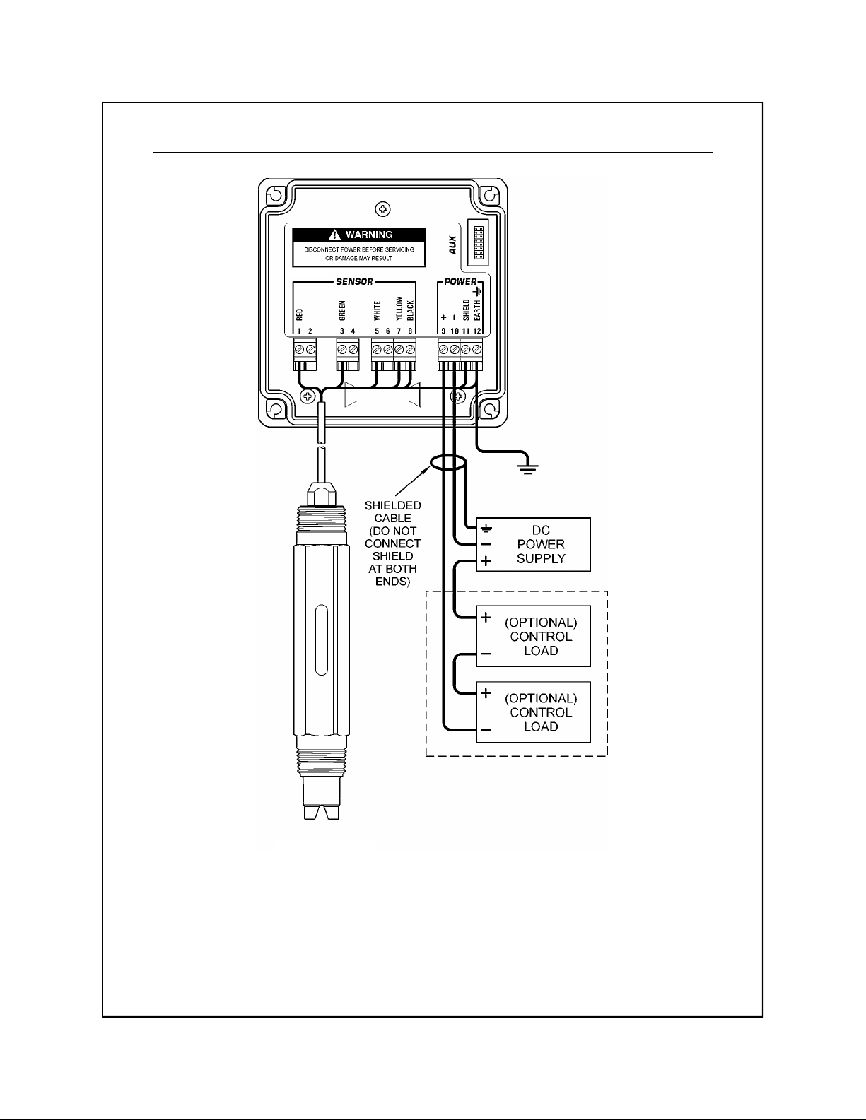
ORE-45P SENSOR
Notes: 1. Voltage between Terminals 9 and 10 MUST be between 16 and 35 VDC.
2. Earth ground into Terminal 12 is HIGHLY recommended. This connection can greatly
improve stability in electrically noisy environments.
Figure 3-1 Loop Power Connection, Omega ORE-45P Sensor and ORTX-45 Transmitter
Rev. B, 05/02
ORTX-45
21
Page 21

Part 2 - Installation 3.2 Electrical-2 wire Version Part 3 - Electrical Installation 3.21 Load Drive Capability
3.21 Load Drive
Capability
The amount of resistance that the analog output can drive
in the 115/230 VAC version is fixed. However, in the twowire configuration, the load-drive level is dependant on the
DC supply voltage provided to the controller.
The two-wire instrument can operate on a power supply
voltage of between 16 and 35 VDC. The available load
drive capability can be calculated by applying the formula
V/I=R, where V=load drive voltage, I=maximum loop
current (in Amperes), and R=maximum resistance load (in
Ohms).
To find the load drive voltage of the two-wire ORTX-45,
subtract 16 VDC from the actual power supply voltage
being used (the 16 VDC represents insertion loss). For
example, if a 24 VDC power supply is being used, the load
drive voltage is 8 VDC.
The maximum loop current of the two-wire ORTX-45 is
always 20.00 mA, or .02 A. Therefore,
(Power Supply Voltage - 16)
R
=
.02
MAX
Rev. B, 05/02
For example, if the power supply voltage is 24 VDC, first
subtract 16 VDC, then divide the remainder by .02.
8/.02 = 400; therefore, a 400 Ohm maximum load can be
inserted into the loop with a 24 VDC power supply.
Similarly, the following values can be calculated:
Power Supply Voltage
Total Load (Ohms)
(VDC)
16.0 0
20.0 200
24.0 400
30.0 700
35.0 950
ORTX-45
22
Page 22

Part 2 - Installation 3.3 Electrical—115/230 vac Version Part 3 - Electrical Installation 3.3 115/230 VAC Configuration
3.3 115/230 VAC
Configuration
In the 115/230 VAC configuration, a DC power supply is
mounted into the inside rear of the enclosure. The power
supply must be ordered with the proper operating voltage.
Verify that the unit requires either 115 VAC or 230 VAC
before installing. Also verify that power is fully disconnected
before attempting to wire.
Connect HOT, NEUTRAL, and GROUND to the matching
designations on terminal strip TB1.
If the unit was ordered with the integral power supply
installed, a connection will also be present from terminal
strip
to the ORTX-45 module. If the power supply
TB2
was ordered separately and installed later, this last
connection at TB2 must be made at this time as shown in
Figure 3-2.
The analog output from the system is present at terminal
TB1. The loop-load limitation in this configuration is 500
Ohms maximum. If the analog output will not be connected
to other instruments, these two terminals must remain
shorted for proper operation.
Note: If not using the 4-20 mA output, a wire short
must exist between terminals (+) and (-) for
proper operation.
Rev. B, 05/02
ORTX-45
23
Page 23
Part 2 - Installation 2.2 Electrical—115/230 VAC Version Part 2 - Installation and Operation 2.3 Electrical
Part 3 - Electrical Installation 3.3 115/230 VAC Configuration
WARNING
Disconnect line power voltage BEFORE connecting
line power wires to Terminal TB1 of the power supply.
The power supply accepts only standard three-wire
single phase power. The power supply is configured
for either 115 VAC or 230 VAC operation at the factory at
time of order, and the power supply is labeled as
such. Do NOT connect voltages other than the labeled
requirement to the input.
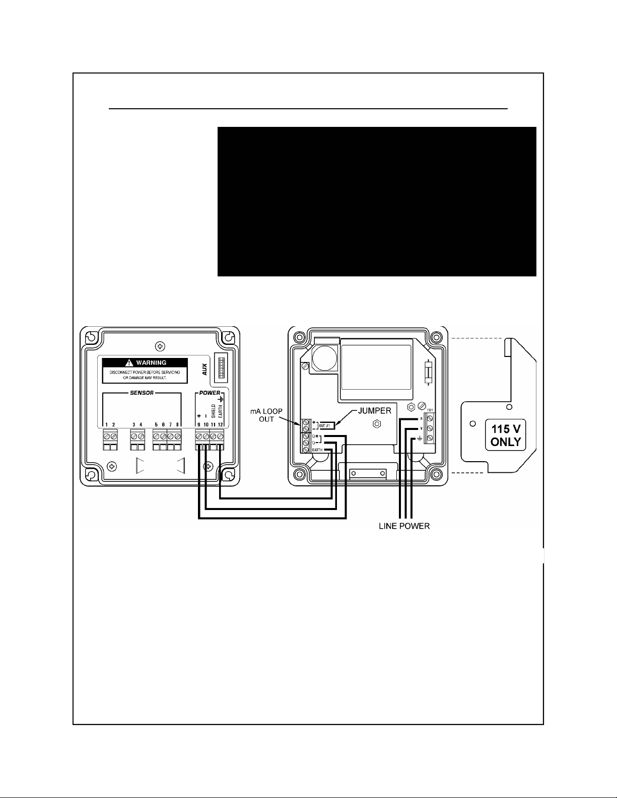
Rev. B, 05/02
Figure 3-2 Line Power Connection
The power strip,
, allows up to 14 AWG wire. A wire
TB1
gauge of 16 AWG is recommended to allow for an easy
pass-through into the PG-9 ports when wiring.
ORTX-45
24
Page 24

Part 2 - Installation 3.4 Electrical—Relay Version Part 3 - Electrical Installation 3.4 115/230 VAC w/ 2 Relays Configuration
3.4 115/230 VAC
w/ 2 Relays
Configuration
In the 115/230 VAC w/ relays configuration, a DC power
supply is mounted into the inside rear of the enclosure.
The power supply must be ordered with the proper operating
voltage. Verify that the unit requires either 115 VAC or
230 VAC before installing. Also verify that power is fully
disconnected before attempting to wire.
Connect HOT, NEUTRAL, and GROUND to the matching
designations on terminal strip TB1.
If the unit was ordered with the integral power supply
installed, a connection will also be present from terminal
strip
to the ORTX-45 module. If the power supply
TB2
was ordered separately and installed later, this last connection at TB2 must be made at this time.
The analog outputs from the system are present at terminal TB2. The loop-load limitation in this configuration 400
Ohms maximum. If the analog output will not be connected to other instruments, these two terminals must remain shorted for proper operation.
Note: If not using the 4-20 mA output #1, a wire
short must exist between terminals (+) and(-)
for proper operation.
Rev. B, 05/02
WARNING
Disconnect line power voltage BEFORE connecting
line power wires to Terminal TB1 of the power supply.
The power supply accepts only standard three-wire
single phase power. The power supply is configured
for either 115 VAC or 230 VAC operation at the factory at
time of order, and the power supply is labeled as
such. Do NOT connect voltages other than the labeled
requirement to the input.
ORTX-45
25
Page 25

Part 3 - Electrical Installation 3.4 115/230 VAC w/ 2 Relays
ORP LOOP
OUT
Figure 3-3 Line Power w/ Relays Connection
Also in the line-power w/ relays configuration, a special
cable is connected under the power supply that runs to the
AUX connector on the main part of the instrument. The
cable is retained by a clip mounted under the AUX connector
on the shield. Under the power supply, the black wire in
the cable should be facing PIN 2. On the AUX connector,
the white wire should be in the upper left corner (see
Figure 3-4 for further details).
Rev. B, 05/02
Figure 3-4 Relay Cable Connection
ORTX-45
26
Page 26

Part 2 - Installation 2.33 Electrical—Relay Version Part 3 - Electrical Installation 3.4 115/230 VAC w/ 2 Relays Part 2 - Installation 2.2 Electrical—115/230 VAC Version Part 2 - Installation and Operation 2.3 Electrical Part 3 - Electrical Installation 3.4 115/230 VAC w/ 2 Relays
Relay Contacts
Two sets of SPDT relay contacts are provided on the relay
option board. None of the relay contacts are powered.
The user must supply the proper power to the contacts.
For applications that require the same switched operating
voltage as the ORTX-45 (115 or 230 V), power may be
jumpered from the power input terminals at
Figure 3-5 Relay Contacts
TB1
.
3.5 Battery-Powered
(Portable)
Configuration
Rev. B, 05/02
In the battery-powered version, the instrument is converted to
a display-only portable unit. The battery option card
cannot be used with any other option cards. All of the
normal software functions are active in the portable unit.
In addition, there are several unique hardware features
which are described in detail here.
Note: Do not attempt to connect external DC or AC
power supplies to the portable unit or severe
damage will result.
ORTX-45
27
Page 27

Part 3 - Electrical Installation 3.5 Battery-Powered Configuration
Installation
ORTX-45 TRANSMITTER
To install the battery board, open the ORTX-45 instrument
enclosure and place the board into the rear of the enclosure
as shown in Figure 3-6. The board should be oriented
such that the header connector P1 is located in the upper
left corner of the enclosure. Fasten the circuit board into
the enclosure at the three indicated mounting points using
the three #4 screws included with the kit. Once the board
is fastened, connect the power cable from header connector
P1 on the battery board to the header located in the AUX
port of the instrument. The blue wire on the ribbon cable
should face down and correspond to the white polarity dot
designating pin 1 on the header connector P1. Finally,
install one alkaline 9 VDC battery into battery holder B1.
Since the header connector is below the shield plate, it
helps to bend the connector “out” slightly on the ribbon
cable before inserting it.
Rev. B, 05/02
Figure 3-6 DC Battery Board Connection
ORTX-45
28
Page 28

Part 2 - Installation 3.5 Electrical—Portable Version Part 3 - Electrical Installation 3.5 Battery-Powered Configuration
Operation
Two hardware switches are located on the battery board:
the power switch S2-PWR and the lock switch S1-LOCK.
The PWR switch disconnects the 9 VDC battery and is
only used to disconnect the battery if the system is not to
be used for a long period of time (> 3 months or storage).
Otherwise, leave this switch in the ON position. The
LOCK switch selects between two different modes of
operation: the normal/off mode or locked/on mode. When
LOCK is in the normal/off mode, the system functions
normally and turns on by holding the MENU key on the
front keypad for 5 seconds. Thereafter, the system will
turn off automatically after 2 hours if no keys are pressed.
When LOCK is in the ON mode, the system is permanently
on and will not turn off. This mode is used for extended
operation.
With the system in normal mode (LOCK = OFF), an alkaline
battery will provide approximately 5 months of noncontinuous operation. Specifically, this would represent
periodic operation of the unit of less than 10 hours per
week. When the system is in locked mode (LOCK = ON),
an alkaline battery will provide approximately 10-14 days
of continuous operation. Installing a 9 VDC lithium battery
instead of alkaline will increase operation time in all
modes by 4x. These projections are dependant upon
which instrument the battery board is operating and the
ambient temperature (higher temperatures will shorten
battery life span).
Rev. B, 05/02
The "B" icon will flash on the LCD when the instrument
requires battery replacement. If the battery is not replaced,
eventually the unit will not turn on in the normal operating
mode. This low-battery indicator functions only when
LOCK = OFF.
ORTX-45
29
Page 29

Part 2 - Installation 3.5 Electrical—Portable Version Part 3 - Electrical Installation 3.5 Battery-Powered Configuration
Notes
Several important points to remember when operating the
instrument with the battery board option:
1. To turn the unit ON, press and hold the MENU key for
5 seconds. The unit will turn off automatically after 2
hours if no keys are pressed.
2. NEVER connect an external power source to the instrument power terminals when the battery board is
installed. Severe damage can result.
3. The 4-20 mA output is not functional when the battery
board is connected. To restore 4-20 mA output
functionality, the battery board must be removed.
4. When using the instrument for portable measurements,
be aware of the time required to achieve stable
readings from particular sensors. In most cases,
sensor primary measurements require stable temperature
readings for accurate temperature compensation. The
user must allow adequate time for the sensor to temperature equilibrate with the solution being measured.
Due to the heavy-duty construction of the ORE-45P
sensor, they may require up to 15 minutes to fully
temperature equilibrate with solutions at temperatures
that are considerably different from the initial sensor
temperature.
Rev. B, 05/02
5. Set the PWR switch to OFF if the unit will not be operated
for an extended period of time, or if it is to be stored.
ORTX-45
30
Page 30

Part 4 - Sensor Connection
4.1 General
The sensor cable can be routed into the enclosure through
one of the provided cord-grip retainers, or through a
properly sized conduit connection. Adapters are available
to convert the PG-9 type opening into a 1/2” NPT type
opening.
If the cord-grip devices are used for sealing the cable,
make sure the cord-grips are snugly tightened after
electrical connections have been made to prevent moisture
incursion. If not using the integral mount method, the
center conduit hole of the enclosure should be plugged
with the provided 1" NPT plug.
When stripping cables, leave adequate length for connections in the transmitter enclosure, as shown below.
Rev. B, 05/02
Figure 4-1 Bulkhead Connection
If the instrument is ordered with the Relay Option Board
installed, the enclosure includes three PG-11 cord grips to
allow for the additional wiring going into the enclosure.
ORTX-45
31
Page 31

Part 4 - Sensor Connection 4.2 ORE-45P Sensor Connection
4.2 ORE-45P Sensor
Connection
Figure 4-2 Sensor Cable Connections, Omega ORE-45P
The sensor cable can be quickly connected to the
ORTX-45 terminal strip by matching the wire colors on
the cable conductors. Route signal cable away from AC
power lines, adjustable frequency drives, motors, or other
noisy electrical signal lines. Do not run sensor or signal
cables in conduit that contains AC power lines or motor
leads. See Figure 4-2 for details on connecting the highperformance Omega sensor (Model ORE-45P).
Rev. B, 05/02
Note: Only the custom 6-wire shielded interconnect
cable must be used when connecting the Model
ORE-45P sensor to the instrument. This highperformance, double shielded, polyethylene
jacketed cable is specially designed to provide
the proper signal shielding for the sensor used
in this system. No substitutions can be made.
Substituted cables may cause problems with
system performance.
For optimum electrical noise rejection performance,
connect the innermost cable shield to the terminal marked
Shield
the terminal marked
on the instrument; connect the outermost shield to
Earth
. In addition, the earth terminal
should also be grounded to a nearby source of electrically
clean ground. Do not allow shield wires to short together.
ORTX-45
32
Page 32

Part 4 - Sensor Connection 4.3 Combination Electrode Connection
4.3 Combination
Electrode
Connection
The ORTX-45 may also be used with non-amplified simple
combination electrodes (see Figure 4-3). Note that a wire
jumper must be installed from Terminal 3 to Terminal 8.
The user must also select Sensor Type 2 within the Config
Menu (see Section 5.24). The maximum sensor-toinstrument cable length will be severely limited (30-50
feet) with electrodes of this type. The length will depend
on the specific electrode impedance and the quality of
interconnect cable provided by the manufacturer.
Rev. B, 05/02
Figure 4-3 Sensor Cable Connections, Combination Electrode
ORTX-45
33
Page 33

Part 4 - Sensor Connection 4.4 External Temperature Compensators
4.4 External
Temperature
Compensators
The Omega ORE-45P sensor includes an integral Pt1000
RTD. The Omega **TX-45 series instruments also allow
user-supplied external Pt1000 or Pt100 elements to be
connected to the temperature input, as shown in Figure
4-4. Note that when using the Pt100 connection, sensor
cable length will be limited to 40 feet due to the high cable
resistance error associated with the lower resistance
output of Pt100 RTD elements. In other words, cable
resistance represents a higher percentage of error signal
when using a lower-resistance RTD.
Rev. B, 05/02
Figure 4-4 External Temperature Compensators
ORTX-45
34
Page 34

Part 4 - Sensor Connection 4.5 Long Cable Length Issues
4.5 Long Cable
Length Issues
Cable Resistance
Very long sensor cable runs (> 400 feet) with relatively
low-Ohm resistive temperature sensors can suffer from
accuracy problems related to additive cable resistance as
well as instability of cable resistance over temperature. In
such cases, a three or four-wire connection method allows
these types of errors to be removed from the measurement.
Although the ORTX-45 is configured as a two-wire RTD
input for ease of connection, the transmitter may be
easily configured as a three-wire element if desired. The
three-wire connection allows the instrument to eliminate
errors caused by changes in the resistance of very long connection leads.
In addition to cable resistance, sensor cable lengths
greater than 400 feet may degrade the electrode diagnostic
signals, resulting in false trips. If this occurs, the glass
diagnostic may be switched off without affecting the remaining system diagnostics. See Section 5.25 for further
details.
The Pt1000 temperature element in the Omega ORE-45P
sensor is a high accuracy, Class A tolerance element.
Tolerance of this element is 0.06% at 0°C, or 0.1°C. In
the standard connection the RTD is configured as a twowire element. The sensor cable on the Model ORE-45P
sensor has a lead resistance of approximately 0.0277Ω/ft
at 68°F. The lead length for the RTD is twice as long as
the sensor cable since two leads are attached to the RTD
element in the sensor. Therefore, 100 feet of sensor
cable represents a possible uncalibrated measurement
error of 200 × 0.0277Ω/ft = 5.54Ω. Since the Pt1000 RTD
has a slope of 0.00385Ω/Ω/°C, this calculates to
5.54Ω/3.85 = 1.44°C. Therefore, this length of sensor
cable can represent a severe error for instruments that do
not allow the user to calibrate temperature. Using the
standard two-wire connection, the ORTX-45 transmitter
allows the user to calibrate out these errors up to
approximately 400 feet of sensor cable.
Rev. B, 05/02
ORTX-45
35
Page 35

Part 4 - Sensor Connection 4.5 Long Cable Length Issues
Cable
Temperature Shift
Three-Wire RTD
Connection
In addition to cable length errors, the user must consider
the effects of temperature changes on the sensor cable
itself. The wire in the ORE-45P sensor is copper, and the
temperature coefficient for copper is 0.00393/°C. When
mounted indoors, the effects of temperature change over
the entire length of cable are negligible. However, long
lengths of cable mounted outdoors may undergo appreciable
shifts in resistance over temperature, causing large errors.
Using the temperature coefficient, 100 feet of cable can
result in an error of approximately 0.3°C over a 50°C
change from standardization. This type of error cannot be
calibrated out. It can only be removed by utilizing the
three-wire connection scheme (see below). However, this
error is unusual in that the entire cable length must
change by the same temperature.
For sensor cable distances of 400 feet or more, a threewire RTD connection will produce the highest accuracy
measurement. This connection requires the use of a
junction box. To configure the instrument for a three-wire
connection, the metal PCB shield over the terminal strips
must be carefully removed by first removing the three
retaining screws, then gently prying the shield upward and
slightly pushing the terminal strips through the opening in the
shield. Once the shield has been removed, the user must
cut a small white jumper J1 in the lower-right section of
the top scaling board. Replace the shield and connect the
Model ORE-45P sensor as shown in Figure 4-5. If the
two-wire connection is desired at any time after this
change has been made, the user must install a wire
jumper between terminals 6 and 7 on the transmitter.
Rev. B, 05/02
ORTX-45
36
Page 36

Part 4 - Sensor Connection 4.5 Long Cable Length Issues
ORTX-45 TRANSMITTER
When utilizing the 3-wire RTD connection, a wire jumper
*
must be made between the yellow and blue wires in the
junction box as shown. The blue wire on the connecting
sensor cable must be attached to Terminal 6 in the
ORTX-45 Transmitter as shown. In addition, a jumper
on the scaling board must also be removed. Refer to
Page 36 for further details.
Connecting sensor cable lengths can be up to 400 feet
with a 2-wire RTD connection, and up to 3,000 feet with a
3-wire RTD connection.
When utilizing the junction box connection, the blue wire
on the connecting sensor cable must be attached to
Terminal 6 on the ORTX-45 Transmitter, as above. However, the blue wire on the ORE-45P Sensor cable is not
used.
Use ONLY the provided sensor interconnect cable between
the transmitter and the junction box.
Figure 4-5 Junction Box Connection and Three-Wire RTD Connection
Rev. B, 05/02
ORTX-45
37
ORE-45P SENSOR
Page 37

Part 5 - Operation
5.1 User Interface
The user interface for the ORTX-45 instrument consists of
a custom display and a membrane keypad. All functions
are accessed from this user interface (no internal jumpers,
pots, etc.).
Rev. B, 05/02
(Display shown with all segments ON)
Figure 5-1 User Interface
ORTX-45
38
Page 38

Part 5 - Operation 5.11 Keys
5.11 Keys
All user configuration occurs through the use of four
membrane keys. These keys are used as follows:
MENU/ESC
To scroll through the menu section
headers or to escape from anywhere in
software. The escape sequence allows
the user to back out of any changes in a
logical manner. Using the escape key
aborts all changes to the current screen
and backs the user out one level in the
software tree. The manual will refer to this
key as either MENU or ESC, depending
upon its particular function.
UP
(arrow)
To scroll through individual list or display
items and to change number values.
LEFT
(arrow)
To move the cursor from right to left during
changes to a number value.
ENTER To select a menu section or list item for
change and to store any change.
5.12 Display
Main Parameter
Rev. B, 05/02
The large custom display provides clear information for
general measurement use and user configuration. There
are three main areas of the display: the main parameter
display, the secondary message line, and the icon area.
During normal operation, the main parameter display
indicates the present process input with sign and units.
This main display may be configured to display any of the
main measurements that the system provides. During
configuration, this area displays other useful set-up information to the user.
ORTX-45
39
Page 39

Part 5 - Operation 5.12 Display
Lower Line
Icon Area
During normal operation, the lower line of the display
indicates user-selected secondary measurements that the
system is making. This also includes calibration data from
the last calibration sequence and the instrument model
number and software version. During configuration, the
lower line displays menu items and set-up prompts to the
user. Finally, the lower line will display error messages
when necessary. For a description of all display messages,
refer to Section 7.3.
The icon area contains display icons that assist the user in
set-up and indicate important states of system functions.
The CAL, CONFIG, and DIAG icons are used to tell the
user what branch of the software tree the user is in while
scrolling through the menu items. This improves software
map navigation dramatically. Upon entry into a menu, the
title is displayed (such as CAL), and then the title disappears
to make way for the actual menu item. However, the icon
stays on.
HOLD
FAIL
Rev. B, 05/02
The HOLD icon indicates that the current output of the instrument has been put into output hold. In this case, the
output is locked to the last input value measured when the
HOLD function was entered. HOLD values are retained
even if the unit power is cycled.
The FAIL icon indicates that the system diagnostic
function has detected a problem that requires immediate
attention. This icon is automatically cleared once the
problem has been resolved.
ORTX-45
40
Page 40

Part 5 - Operation 5.12 Display
Relay Area A/B
5.2 Software
The relay area contains two icons that indicate the state of
the system relays (if the relay card is installed). If the
battery board is installed instead, the B icon indicates that
the battery voltage is at a low level. The battery power
option and the relay option cannot be installed together.
The software of the ORTX-45 is organized in an easy to
follow menu-based system. All user settings are organized under four menu sections: Measure, Calibration
[CAL], Configuration [CONFIG], and Diagnostics [DIAG].
Note: The default Measure Menu is display-only and has no
menu icon.
5.21 Software
Navigation
Rev. B, 05/02
Within the CAL, CONFIG and DIAG menu sections is a list
of selectable items. Once a menu section (such as
CONFIG) has been selected with the MENU key, the user
can access the item list in this section by pressing either
the ENTER key or the UP arrow key. The list items can
then be scrolled through using the UP arrow key. Once
the last item is reached, the list wraps around and the first
list item is shown again. The items in the menu sections
are organized such that more frequently used functions
are first, while more permanent function settings are later
in the list. See Figure 5-2 for a visual description of the
software.
ORTX-45
41
Page 41

Part 5 - Operation 5.21 Software Navigation
Each list item allows a change to a stored system variable.
List items are designed in one of two forms: simple single
variable, or multiple variable sequence. In the single
variable format, the user can quickly modify one parameter for example, changing temperature display units from °F
to °C. In the multiple variable sequence, variables are
changed as the result of some process. For example, the
calibration of ORP generally requires more than one piece
of information to be entered. The majority of the menu
items in the software consist of the single variable format
type.
Any data that may be changed will be flashing. This
flashing indicates user entry mode and is initiated by
pressing the ENTER key. The UP arrow key will increase
a flashing digit from 0 to 9. The LEFT arrow key moves
the flashing digit from right to left. Once the change has
been completed, pressing ENTER again stores the variable
and stops the flashing. Pressing ESC aborts the change
and also exits user entry mode.
The starting (default) screen is always the Measure Menu.
The UP arrow key is used to select the desired display.
From anywhere in this section the user can press the
MENU key to select one of the four Menu Sections.
The UP arrow icon next to all list items on the display is a
reminder to scroll through the list using the UP arrow key.
Rev. B, 05/02
ORTX-45
42
Page 42

(
)
(
)
)
y
Part 5 - Operation 5.21 Software Navigation
MENU
SECTIONS
Te mp er atu re
Loop Cu rrent (ORP- #1)
Loop Current (°C/°F- #2)
*
Sensor Offset
Model/Version
**
LIST
ITEMS
Start
MEASURE
(displ ay only)
mV
Tim er Sta tu s
MENU
ESC
Relay A= FAIL
CAL CONFIG DIAG
ENTER ENTER ENTER
or
Cal ORP
Cal Temp
Cal TC Fact
MENU
ESC
Set 4mA
Set 20mA
Set 4mA (°C/°F- #2
*
or
Entry Lock
*
Set Delay
Relay A= AL
Setpnt A- HI
*
Delay A- HI
*
Setpnt A- LO
*
Delay A- LO
*
Phase A
*
Relay A= CON
Setpnt A
*
Delay A
*
Phase A
*
ORP- #1
ORP- #1
(°C/°F- #2)Set 20mA
MENU
ESC
or
Set Hold
Fault List
Sim Out
Fail Out
Glass Diags
Failsa fe
*
Rly A Mode
*
Rly B Mode
*
Default All
MENU
ESC
Rev. B, 05/02
Relay B= FAIL
Relay B= SENS
Tim er B ON
*
Relay B= CON
Setpnt B
*
Delay B
*
Phase B
*
Contrast
Displa
Temp Un its
Temp Input
Select TC
Sensor Type
Figure 5-2 Software Map
ORTX-45
43
Functions enabled
*
with Relay Option Card
Enabled with Relay
**
Option Card when
timer is enabled
(Relay B = SENS)
Page 43

Part 5 - Operation 5.21 Software Navigation
To select a list item for modification, first select the proper
menu with the MENU key. Scroll to the list item with the
UP arrow key and then press the ENTER key. This tells
the system that the user wishes to perform a change on
that item. For single item type screens, once the user
presses the ENTER key, part or all of the variable will
begin to flash, indicating that the user may modify that
variable using the arrow keys. However, if the instrument
is locked (see Section 5.24), the instrument will display the
message Locked! and will not enter user entry mode.
The instrument must be unlocked by entering the proper
code value to allow authorized changes to user entered
values. Once the variable has been reset, pressing the
ENTER key again causes the change to be stored and the
flashing to stop. The message Accepted! will be displayed
if the change is within pre-defined variable limits. If the
user decides not to modify the value after it has already
been partially changed, pressing the ESC key aborts
the modification and returns the entry to its original stored
5.22 Default Menu
In a menu item which is a multiple variable sequence type,
once the ENTER key is pressed there may be several
prompts and sequences that are run to complete the
modification. The ESC key can always be used to abort
the sequence without changing any stored variables.
The default menu for the system is a display-only measurement menu. This menu has no changeable list items and no
navigation icon. When left alone, the instrument will automatically return to this menu after approximately 30 minutes.
While in the default menu, the UP arrow key allows the
user to scroll through the secondary variables on the lower
line of the display, including temperature, current output,
offset data from the last calibration, model number/software
version, and timer status for Relay B (if enabled). Variables
displayed on the lower line will not duplicate the main
display (i.e., the instrument cannot show mV on both the
main and secondary displays).
Rev. B, 05/02
ORTX-45
44
Page 44

Part 5 - Operation 5.22 Default Menu
The timer status screen is only displayed if the probe timer
feature is enabled (available with optional Relay Card), by
setting Relay B Mode =
SENS
(see Section 5.25). The
screen shows the present phase of the timer, as well as how
much time is left before the next phase.
Note: A timer wash cycle can be manually started by
pressing and holding the ENTER key for a few
seconds while viewing the timer status screen in
the Default Menu. The timer must be in the
“OFF” state to allow a manual start (“T” is not
flashing on the display). After this forced cycle,
the system will return to normal.
A display test (all segments ON) can be actuated by
pressing and holding the ENTER key while viewing the
model/version number on the lower line of the display.
5.23 Calibration Menu
[CAL]
Cal ORP
Cal Temp
Cal TC Factor
The calibration menu contains items for frequent calibration
of user parameters. There are three items in this list: Cal
ORP, Cal Temp, and Cal TC Factor.
The ORP calibration menu offers two choices for calibration
of ORP: 2-point and 1-point (sample) methods. See Part 6 Calibration for more details.
The temperature calibration function allows the user to
adjust the offset of the temperature response by a small
factor of ±5 °C. The temperature input is factory calibrated to
very high accuracy. However, very long cable lengths and
junction boxes may degrade the accuracy of the temperature
measurement in some extreme situations. Therefore, this
feature is provided only as an adjustment. Modifying the
present temperature calibration is not recommended since
it can be very difficult to obtain a highly accurate and
stable reference solution as a reference. See Part 6 Calibration for more details.
This function is intended to give the user direct control of
the temperature calibration offset value without having to perform an entire temp cal procedure. See Part 6 - Calibration
for more details.
Rev. B, 05/02
ORTX-45
45
Page 45

Part 5 - Operation 5.24 Configuration Menu
5.24 Configuration
Menu
[CONFIG]
Entry Lock
Set 4 mA
[ORP]
The Configuration Menu contains all of the general user
settings:
This function allows the user to lock out unauthorized
tampering with instrument settings. All settings may be
viewed while the instrument is locked, but they cannot be
modified. The Entry Lock feature is a toggle-type setting;
that is, entering the correct code will lock the transmitter
and entering the correct code again will unlock it. The
code is preset at a fixed value. Press ENTER to initiate
user entry mode and the first digit will flash. Use arrow
keys to modify value.
The ORTX-45 lock/unlock code is
1452. Press ENTER to toggle lock setting once code is
correct. Incorrect codes do not change state of lock
condition.
This function sets the main 4 mA current loop output point
for the instrument. When the Relay Option Board is installed,
the display will read
Set 4 mA #1
. The value stored for
this point may be higher or lower than the value stored for
the 20 mA point. The entry value is limited to a value
between –1000 and +2000 mV, and the 4 mA and the 20
mA point must be at least 100 mV away from each other.
Press ENTER to initiate user entry mode, and the value
will flash. Use arrow keys to modify value; range is –1000
to +2000 mV. Press ENTER to store the new value.
Set 20 mA
[ORP]
Rev. B, 05/02
This function sets the 20 mA current loop output point for
the instrument. When the Relay Option Board is installed,
the display will read
Set 20 mA #1
. The value stored for
this point may be higher or lower than the value stored for
the 4 mA point. The entry is limited to a value between –1000
and +2000 mV, and the 20 mA point and the 4 mA point
must be at least 100 mV away from each other. Press
ENTER to initiate user entry mode, and the value will
flash. Use arrow keys to modify value; range is –1000 to
+2000 mV. Press ENTER to store the new value.
ORTX-45
46
Page 46

Part 5 - Operation 5.24 Configuration Menu
*Set 4 mA #2
[temp]
*Set 20 mA #2
[temp]
ONLY AVAILABLE WITH RELAY OPTION BOARD
.
This function sets the second 4 mA current loop output
point for the transmitter. The value stored for this point
may be higher or lower than the value stored for the 20
mA point. The entry value is limited to a value between 0
and 110 °C, and the 4 mA and the 20 mA point must be at
least 10 °C units away from each other. Press ENTER to
initiate user entry mode, and the value will flash. Use
arrow keys to modify value; range is 0.0 to 110.0 °C.
Press ENTER to store the new value. The optional temperature output is a monitoring type output. It does not
include bumpless transfer, simulate, or fail mode features.
However, HOLD does affect this output.
ONLY AVAILABLE WITH RELAY OPTION BOARD.
This function sets the second 20 mA current loop output
point for the transmitter. The value stored for this point
may be higher or lower than the value stored for the 4 mA
point. The entry is limited to a value between 0 and 110 °
C, and the 20 mA point and the 4 mA point must be at
least 10 °C units away from each other. Press ENTER to
initiate user entry mode, and the value will flash. Use
arrow keys to modify value; range is 0.00 to 110.0 °C.
Press ENTER to store the new value. The optional temperature output is a monitoring type output. It does not
include bumpless transfer, simulate, or fail mode features.
However, HOLD does affect this output.
Set Delay
Rev. B, 05/02
The delay function sets the amount of damping on the
instrument. This function allows the user to apply a first
order time delay function to the ORP measurements being
made. Both the display and the output value are affected
by the degree of damping. Functions such as calibration
are not affected by this parameter. The calibration routines
contain their own filtering and stability monitoring functions
to minimize the calibration timing. Press ENTER to initiate
user entry mode, and the value will flash. Use the arrow
keys to modify value; range is 0.1 to 9.9 minutes.
Press ENTER to store the new value.
ORTX-45
47
Page 47

Part 5 - Operation 5.24 Configuration Menu
*Setpnt A
*Hyst A
*Delay A
ONLY AVAILABLE WITH RELAY OPTION BOARD.
This function establishes the setpoint, or “trip” point for
Relay A. The entry value is limited to a value between –1000
and +2000 mV. Press ENTER to initiate user entry mode,
and the value will flash. Use arrow keys to modify value;
range is –1000 and +2000 mV. Press ENTER to store the
new value.
ONLY AVAILABLE WITH RELAY OPTION BOARD.
This function establishes the hysteresis, or “deadband”,
for Relay A. Hysteresis is most often used to control relay
chattering; however, it may also be used in control
schemes to separate between the ON/OFF trip points of
the relay. Press ENTER to initiate user entry mode, and
the value will flash. Use the arrow keys to modify value;
range is +5 mV to +2000 mV. Press ENTER to store the
new value.
ONLY AVAILABLE WITH RELAY OPTION BOARD.
This function places an additional amount of time delay on
the trip point for Relay A. This delay is in addition to the
main delay setting for the controller. The entry value is limited to a value between 0 and 999 seconds. Press ENTER
to initiate user entry mode, and the value will flash. Use
arrow keys to modify value; range is 0 to 999 seconds.
Press ENTER to store the new value.
Rev. B, 05/02
See Figure 5-3 for a visual description of a typical control
relay application.
ORTX-45
48
Page 48

Part 5 - Operation 5.24 Configuration Menu
When value rises to ≥ +600 mV, relay closes.
ON
+600 mV
PHASE: HI
+500 mV
OFF
When value falls to ≤ +500 mV, relay opens.
Settings:
Setpoint: +600 mV
Hyst: +100 mV
Delay: 000
Failsafe: OFF
When value falls to ≤ +600 mV, relay closes.
OFF
+700 mV
PHASE: LO
+600 mV
ON
HYSTERESIS
}
"DEAD BAND"
HYSTERESIS
}
"DEAD BAND"
OR
OR
*Phase A
When value rises to ≥ +700 mV, relay opens.
Figure 5-3 Control Relay Example
ONLY AVAILABLE WITH RELAY OPTION BOARD.
This function establishes the direction of the relay trip.
When phase is HI, the relay operates in a direct mode.
Therefore, the relay energizes and the LCD indicator
illuminates when the mV value
exceeds
the setpoint.
When the phase is LO, the relay energizes and the LCD
indicator illuminates when the mV drops
below
the setpoint.
The failsafe setting does have an impact on this logic.
The description here assumes that the failsafe setting is
OFF. Press ENTER to initiate user entry mode, and the
entire value will flash. Use the UP arrow key to modify the
desired value; selections include HI for direct operation or
for reverse operation. Press ENTER to store the new
LO
value.
Rev. B, 05/02
ORTX-45
49
Page 49

Part 5 - Operation 5.24 Configuration Menu
*Setpnt A-HI
*Hyst A-HI
*Delay A-HI
*Setpnt A-LO
*Hyst A-LO
*Delay A-LO
PHASE: HI
Settings:
Setpoint A-HI: +600 mV
Hyst A-HI: +100 mV
Delay A-HI: 000
Setpoint A-LO: +200 mV
Hyst A-LO: +100 mV
Delay A-LO: 000
ONLY AVAILABLE WITH RELAY OPTION BOARD.
If Relay A Mode is set to Alarm Mode, AL (see Section
5.25), then the following settings will appear in the Config
Menu list automatically. In this mode, two setpoints can
be selected on the same relay, to create an alarm band.
Phase HI selection causes the relay to energize outside of
the band, and Phase LO causes the relay to energize
inside of the band. This feature enables one relay to be
used as a control relay while the other is used as a HILO Alarm relay at the same time.
See Figure 5-4 for a visual description of a typical
alarm relay application.
+600 mV
+500 mV
OFF
+300 mV
+200 mV
When value rises to ≥ +600 mV, relay closes,
until value falls back to ≤ +500 mV.
ON
HYST - HI
}
HYST - LO
}
ON
When value falls to ≤ +200 mV, relay closes,
until value rises back to ≥ +300 mV.
When value falls to ≤ +600 mV, relay closes,
until value rises back to ≥ +700 mV.
Rev. B, 05/02
OFF
+700 mV
+600 mV
PHASE: LO
+200 mV
+100 mV
OFF
Figure 5-4 Alarm Relay Example
ORTX-45
50
HYST - HI
}
ON
HYST - LO
}
When value rises to ≥ +200 mV, relay closes,
until value falls back to ≤ +100 mV.
Page 50

Part 5 - Operation 5.24 Configuration Menu
*Setpnt B
*Hyst B
*Delay B
*Phase B
*Timer B ON
*Timer B OFF
*Timer B HOLD
ONLY AVAILABLE WITH RELAY OPTION BOARD.
If Relay B Mode is set to CON (see Section 5.25), then
Relay B will function identically to Relay A. Relay B settings
will appear in the CONFIG menu list automatically.
ONLY AVAILABLE WITH RELAY OPTION BOARD
If Relay B Mode is set to
SENS
(see Section 5.25), these
.
timer settings will appear in the menu list automatically.
Relay B will toggle ON and OFF based on the time settings
entered by the user. The timer ON setting controls the
amount of time that Relay B is engaged (N.O. contact
closed), and the timer OFF setting controls the amount
of time that Relay B is released (N.O. contact open).
The timer HOLD setting allows an output hold time to be
entered into the ON/OFF cleaning cycle. This hold time
allows the outputs to stabilize back to normal readings before
the outputs are changed. Using this feature allows the
unit output to appear undisturbed by the cleaning action of
the hardware.
Rev. B, 05/02
Example: If the timer-ON setting is 5 minutes, the timerOFF setting is 1 hour, and the timer-HOLD setting is 2
minutes, the following sequence will occur: At the instant
the timer is enabled, or data for ON/OFF/HOLD is modified,
the “OFF” time period begins. Once the 1-hour OFF
period ends, the outputs will be put in HOLD and relay B
will engage for 5 minutes (ON time). After the 5 minutes
have expired, relay B will be released but the hold will stay
locked in for an additional 2 minutes (HOLD time), retaining
the original output signals. Then, the entire cycle will
repeat - the output hold will be released and relay B will
stay off for 1 hour, etc.
Since most cleaning cycles will typically occur daily or
weekly, it is most likely that the OFF time will be set to a
number like 24 hours or perhaps as much as 168 hours
(approximately 1 week). If the HOLD timer function is set
to 0, the output hold function is released immediately as
relay B is released.
ORTX-45
51
Page 51

Part 5 - Operation 5.24 Configuration Menu
Note: The sensor wash timer is not based on a “real-
time” clock circuit. Therefore, the time accuracy is
only within approximately 10 minutes per day.
If the B mode selection is changed from
SENS
to
FAIL
or
CON while the probe washer is in mid-cycle (and the
HOLD is enabled), the HOLD must be turned off manually
to return all of the outputs to normal operation. A flashing
"T" will be seen on the lower line of the display next to
temperature while the probe cleaner function is operating.
The entry value for each timer setting has a maximum value
of 10 minutes/999 hours/999 minutes for the ON/OFF/
HOLD functions, respectively. Press ENTER to initiate
user entry mode, and the entire value will flash. Use
arrow keys to modify the desired value. Press ENTER to
store the new value.
Note: A timer wash cycle can be manually started by
pressing and holding the ENTER key for a few
seconds while viewing the timer status screen in
the Default Menu. The timer must be in the
“OFF” state to allow a manual start (“T” is not
flashing on the display). After this forced cycle,
the system will return to normal.
Contrast
Rev. B, 05/02
This function sets the contrast level for the display. The
custom display is designed with a wide temperature
range, Super-Twist Nematic (STN) fluid to provide the
highest possible contrast ratio and widest viewing angle
under all conditions. Contrast control of this type of display is
generally not necessary, so contrast control is provided as
a means for possible adjustment due to aging at extreme
ranges. In addition, the display has an automatic temperature compensation network. Press ENTER to initiate
user entry mode, and the value will flash. The contrast
value is not updated until the new value is entered. Use
arrow keys to modify the value; range is 0 to 9 (0 being
lightest). Press ENTER to store the new value.
ORTX-45
52
Page 52

Part 5 - Operation 5.24 Configuration Menu
Display
Temp Units
Temp Input
This function allows the user to change the measurement
in the primary display area. The user may select between
sensor millivolts, sensor temperature, or output current.
Using this function, the user may choose to put temperature
in the main display area and mV on the secondary, lower
line of the display. Press ENTER to initiate user entry
mode, and the entire value will flash. Use the UP arrow
key to modify the desired display value. Press ENTER to
store the new value.
This function sets the display units for temperature. Press
ENTER to initiate user entry, and the entire value will flash.
Use the UP arrow key to modify the display value. The
choices are °F and °C. Press ENTER to store the new value.
This function allows the user to manually lock the temperature at a fixed value of 25 °C. Once locked at 25 °C, a small
appears next to the temperature value on the lower line of
m
the display to indicate to the user that the system is in manual
lock mode. All temperature compensation is defeated when
in manual lock mode. Press ENTER to initiate user entry,
and the entire value will flash. Use the UP arrow key to
modify the value; selections are SENS for sensor input or
for fixed at 25 °C. Press ENTER to store the new value.
F25
Select TC
Sensor Type
Rev. B, 05/02
This function allows the user to select either a Pt1000 or
Pt100 platinum RTD temperature element. The Pt1000
element is the standard element in all high performance
Omega **E-45P sensors; it is the recommended temperature
sensing element for all measurements. The Pt100 selection
is provided as an alternative for use with existing combination-style sensors. Press ENTER to initiate user entry mode,
and the entire value will flash. Use the UP arrow key to modify the desired value. Press ENTER to store the new value.
This function sets the sensor input type. This selection is
critical for control of the internal diagnostics and compensation factors. Press ENTER to initiate user entry mode,
and the entire value will flash. Use the UP arrow key to
modify the desired value. Selections are 1 for Quantum
sensor, and 2 for combination electrode. Press ENTER to
store the new value.
ORTX-45
53
Page 53

Part 5 - Operation 5.25 Diagnostics Menu
5.25 Diagnostics
Menu [DIAG]
Set Hold
The diagnostics menu contains all of the user settings that
are specific to the system diagnostic functions, as well as
functions that aid in troubleshooting application problems.
The Set Hold function locks the current loop output values
on the present process value. This function can be used
prior to calibration, or when removing the sensor from the
process, to hold the output in a known state. Once HOLD
is released, the outputs return to their normal state of
following the process input. The transfer out of HOLD is
bumpless on the main output #1 (ORP) - that is, the
transfer occurs in a smooth manner rather than as an
abrupt change. An icon on the display indicates the
HOLD state, and the HOLD state is retained even if power
is cycled. Press ENTER to initiate user entry mode, and
entire value will flash. Use the UP arrow key to modify the
desired value, selections are ON for engaging the HOLD
function, and
ENTER to store the new value.
Note:
When the Relay Option Board is installed, the Set
to disengage the function. Press
OFF
Hold function holds BOTH current levels, as well as ALL
relay settings. When the Set Hold function is released,
the transfer is bumpless only on the ORP output (current
loop #1).
Fault List
Rev. B, 05/02
The Set Hold function can also hold at an output value
specified by the user. To customize the hold value, first
turn the HOLD function on. Press the ESC key to go to
the DIAG Menu and scroll to Sim Output using the UP
arrow key. Press ENTER. Follow the instructions under
Sim Output (see following page).
The Fault List screen is a read-only screen that allows the
user to display the cause of the highest priority failure.
The screen indicates the number of faults present in the
system and a message detailing the highest priority fault
present. Note that some faults can result in multiple
displayed failures due to the high number of internal tests
occurring. As faults are corrected, they are immediately
cleared.
ORTX-45
54
Page 54

Part 5 - Operation 5.25 Diagnostics Menu
Faults are not stored; therefore, they are immediately
removed if power is cycled. If the problem causing the
faults still exists, however, faults will be displayed again
after power is re-applied and a period of time elapses
during which the diagnostic system re-detects them. The
exception to this rule is the calibration failure. When a
calibration fails, no corrupt data is stored. Therefore, the
system continues to function normally on the data that
was present before the calibration was attempted. If
power to the instrument is cycled, the failure for calibration
will be cleared until calibration is attempted again. If the
problem still exists, the calibration failure will re-occur.
Press ENTER to initiate view of the highest priority failure.
The display will automatically return to normal after a few
seconds.
Sim Out (ORP)
The Sim Out function allows the user to simulate the main
current loop output [ORP] of the instrument once it has
been configured. The user enters a loop current value
directly onto the screen, from 4.00 mA to 20.00 mA, and
the output responds as if it were actually receiving the
signal from the sensor. This allows the user to check the
function of attached monitoring equipment during set-up or
troubleshooting. Escaping this screen returns the unit to
normal operation. Press ENTER to initiate the user entry
mode, and the right-most digit of the value will flash. Use
arrow keys to modify desired value. The starting display
value will be the last read value of the input. The output
will be under control of the SIM screen until the ESC key
is pressed.
Note: If the HOLD function is engaged before the Sim
Output function is engaged, the simulated output
will remain the same even when the ESC key is
pressed. Disengage the HOLD function to return to
normal output.
Rev. B, 05/02
ORTX-45
55
Page 55

Part 5 - Operation 5.25 Diagnostics Menu
Fail Out
Glass Diags
This function sets the condition of the main current loop
output [ORP] under a FAIL condition. The output may be
forced to 4 mA, 20 mA, or the feature may be disabled. As
an example of the use of this feature, the user may set up
a usable mV output range from –1000 to +2000 mV
across an output span of 5 mA to 19 mA. With the Fail
Out setting of 4 mA, any alarm condition will cause the
current loop output to drop outside the normal operating
range, indicating a system failure that requires attention.
In this way, a failure can be distinguished from normal operating levels. Press ENTER to initiate user entry mode,
and the entire value will flash. Use the UP arrow key to
modify desired value; selections are 4mA, 20mA, or OFF.
Press ENTER to store the new value.
This function allows the user to shut off the glass
breakage/leak diagnostics. It does not affect the state of
the remaining system diagnostics. This capability is
provided to eliminate nuisance trips in electrically noisy
applications, such as some plating operations. If ON,
Relay B is automatically configured as a fail alarm relay.
The relay trips on any fail condition. Therefore, the normal
settings for control Relay B will disappear from the
CONFIG menu since they cannot be used.
Rev. B, 05/02
Note that the probe timer function can also alter the operation
of Relay B. If the electrode diagnostic function is enabled,
that function takes precedence over the probe timer.
Press ENTER to initiate user entry mode, and the entire
value will flash. Use the UP arrow key to modify desired
value; selections are ON to engage the function,
OFF
to
disengage the function. Press ENTER to store the new
value.
ORTX-45
56
Page 56

Part 5 - Operation 5.25 Diagnostics Menu
*Failsafe
ONLY AVAILABLE WITH RELAY OPTION BOARD.
This function allows the user to set the optional system
relays to a failsafe condition. In a failsafe condition, the
relay logic is reversed so that the relay is electrically
energized in a normal operating state. By doing this, the
relay will not only change state when, say, an mV limit
is exceeded, but also when power is lost to the controller.
When failsafe is selected to be ON, the normally-open
contacts of the relay will be closed during normal operation.
In an attempt to make this configuration less confusing,
the LCD icon logic is reversed with this setting, and the
icon is OFF under this normal condition. Therefore, when
the trip condition occurs, the closed N.O. contacts will be
opened (relay de-energized), and the LCD icon will illuminate. In addition, a power fail would also cause the same
contacts to open.
Press ENTER to initiate user entry mode, and the entire
value will flash. Use the UP arrow key to modify desired
value; selections are ON to engage the function,
OFF
to
disengage the function. Press ENTER to store the new
value.
*Rly A Mode
Rev. B, 05/02
ONLY AVAILABLE WITH RELAY OPTION BOARD.
Relay A can be used in three different ways: as a setpoint
control, as a fail alarm, or as a HI-LO alarm band. The
three settings for Rly A Mode are CON for control mode,
FAIL for fail alarm mode, and AL for HI-LO alarm.
The
setting enables normal control operation for
CON
Relay A, with settings for setpoint, hysteresis, phasing,
and delay appearing in the CONFIG menu automatically.
The
setting enables the fail alarm mode for Relay
FAIL
A. Relay A will then trip on any condition that causes the
FAIL icon to be displayed on the LCD. Using this mode
allows the User to send alarm indications to other remote
devices.
ORTX-45
57
Page 57

Part 5 - Operation 5.25 Diagnostics Menu
The AL setting allows two setpoints to be selected for
the same relay, producing a HI-LO alarm band. In this
mode, Relay A will trip inside or outside of the band,
depending upon the Phase selected. See Figure 5-4
for further details.
*Rly B Mode
ONLY AVAILABLE WITH RELAY OPTION BOARD.
Relay B can be used in a number of ways: as a setpoint
control, as a fail alarm, or as a timer. Relay B can be
used with accessory probe washers or other attached
equipment that requires a periodic contact enclosure. The
three settings for Relay B Mode are
for control
CON
mode, FAIL for fail alarm mode, and SENS for timer.
The
setting enables normal control operation for
CON
Relay B. Relay B then operates identically to Relay A,
with settings for setpoint, hysteresis, phasing, and delay
appearing in the CONFIG menu automatically. Using this
mode allows the User to utilize two individual control relays
for process control, high/low alarm applications, etc.
The
setting enables the fail alarm mode for Relay B.
FAIL
Relay B will then trip on any condition that causes the FAIL
icon to be displayed on the LCD. Using this mode allows the
User to send alarm indications to other remote devices.
The
SENS
setting enables the sensor timer mode for
Relay B. Relay B then operates on a cyclic ON/OFF
timer, with individual settings for ON-time and OFF-time
as well as Timer HOLD appearing in the CONFIG menu
automatically. Using this mode allows the User to implement a periodic, automated cleaning system for the sensor.
Default All
Rev. B, 05/02
The Default All function allows the user to return the
instrument back to factory default data for all user settings.
It is intended to be used as a last resort troubleshooting
procedure. All user settings are returned to the original
factory values. Hidden factory calibration data remains
unchanged. Press ENTER to initiate user entry mode and
the value NO will flash. Use the UP arrow key to modify
value to
and press ENTER to reload defaults.
YES
ORTX-45
58
Page 58

Part 6 - Calibration
6.1 Overview
and Methods
The instrument must be calibrated periodically to maintain
a high degree of measurement accuracy. Frequency of
calibration must be determined by the application. High
temperature applications or applications involving other
extreme operating conditions may require more frequent
calibration than those that operate at more ambient level
temperatures. It is important for the user to establish a
periodic cleaning and calibration schedule for sensor
maintenance to maintain high system accuracy.
Before calibrating the instrument for the very first time
after initial installation, it is important to select the proper
operating parameters in the configuration menus for items
like Sensor Type.
ORP calibration solutions can be one of two types:
standard mV solutions, or standard pH buffers with
quinhydrone powder added. For all 2-point calibrations, mV
solutions must be at least 100 mV apart. When using
quinhydrone powder, add slowly to the pH buffer until just
after the quinhydrone ceases to dissolve (approximately 1
tsp. quinhydrone per pint of buffer). Use the following table
as a guideline for reference mV values at nominal pH values:
Rev. B, 05/02
4 pH
20 ºC 25 ºC 30 ºC
20 ºC 25 ºC 30 ºC
7 pH
+268 mV +263 mV +258 mV +92 mV +86 mV +79 mV
CAUTION: Quinhydrone is highly acidic. Follow all safety
instructions on Material Safety Data Sheets.
ORTX-45
59
Page 59

Part 6 - Calibration 6.11 Sensor Slope
6.11 Sensor Slope
6.12 Sensor Offset
The sensor slope is a number (expressed as a percentage)
which represents the current condition of the sensor
electrodes. The slope display is updated after every
calibration. When new, the sensor slope should be between
90% and 110%. A 100% slope represents an ideal sensor
output of 1 mV/1 mV for displayed data vs. factory calibration
data. The slope of the ORP electrode does not degrade
appreciably over the life of the sensor (as compared to a
pH sensor), since the measuring element of the sensor is
basically an exposed metal electrode. However, a very
small slope degradation can occur over a long period of
time as the glass reference electrode ages. Slope calibrations can remove this error along with very small inherent
gain errors in the sensor preamp and electrodes. The
transmitter will not allow calibrations on a sensor with a
slope less than 60% or more than 140%. ORP sensor
slope is only shown at the completion of a successful
calibration.
Sensor offset is a number that indicates sensor output
(expressed in mV) in a theoretical 0 mV solution at 25 ºC.
Ideally, the sensor will output 0 mV under these conditions.
A sensor offset reading of +10 mV indicates that the
sensor will output +10 mV when placed into a theoretically
perfect 0 mV solution at 25 ºC. In other words, sensor
offset shifts the entire response curve up or down.
Changes in sensor offset are generally produced by a
small voltage drop at the sensor reference junction. Large
offsets are most typically the result of foulants on the
reference junction, an aged reference junction, or a weak
reference fill solution. The instrument does not allow
calibrations on a sensor with an offset greater than approximately +200 mV or less than –200 mV. Since sensor
offset is considered an absolute value from the ideal 0 mV
value, readings outside the range of –200 to +200 mV are
considered “high offset” errors during calibration. Sensor
offset information from the most recent calibration can be
viewed at any time in the Default Menu (see Section 5.22).
Rev. B, 05/02
ORTX-45
60
Page 60

Part 6 - Calibration 6.13 2-Point Calibration Explained
The system provides two methods of ORP calibration: 2point and 1-point. These two methods are significantly
different. The following are brief explanations of their uses.
6.13 2-Point
Calibration
Explained
6.14 1-Point
Calibration
Explained
The 2-point calibration method involves the movement of
the sensor through two known mV solution values.
Therefore, the sensor must be removed from the application
to utilize this method. Two-point calibration adjusts both
the slope and the offset of the sensor. Although this
method obtains the highest accuracy, it is not recommended
for frequent calibrations as the slope of the ORP sensor
does not degrade appreciably over time. In addition,
problems can occur in some 2-point calibrations when two
different mV solutions mix in the saltbridge of the sensor.
A precipitant can be formed which can affect offset voltages
in the reference junction.
The 1-point calibration method is generally known as the
"grab sample" calibration method. In the 1-point calibration
method, the sensor may be removed from the application
and placed into one mV solution. It may also be left in the
measurement process and calibrated by reference. 1point calibration adjusts only the sensor offset. It is the
recommended method for frequent ORP calibrations.
Rev. B, 05/02
ORTX-45
61
Page 61

Part 6 - Calibration 6.2 Performing a 2-Point Calibration
6.2 Performing a
2-Point
Calibration
Procedure
Two-point calibration adjusts both the slope and the offset
of the sensor. Slope relates to how closely the system
matches displayed mV with actual mV. Offset is the actual
difference over the entire output curve between actual and
displayed mV. Two point calibrations are not recommended
for frequent calibrations as the slope of the ORP sensor
does not degrade appreciably over time. However, two-point
calibration does provide the highest level of accuracy.
1. Remove sensor from application. Rinse and clean if
necessary.
2. Allow sensor to temperature equilibrate with the solution
as best as possible. With the sensor coming from an
application solution that differs greatly in temperature
from the calibration solution, the user may have to wait
as much as 20 minutes for this to occur.
3. Scroll to the CAL menu section using the MENU key
and press ENTER or the UP arrow key. Cal ORP will
then be displayed.
4. Press the ENTER key. The screen will display a
flashing 1 for 1-point or a 2 for 2-point calibration.
Using the UP arrow key, set for a 2-point calibration
and press ENTER.
5. The display will prompt the user to place the sensor in
the first mV solution and press ENTER. If the sensor
has been placed into this solution already, once the
temperature has stabilized, press ENTER to continue.
6. The present mV value will be displayed and the secondary line of the display will flash Wait for approximately
10-15 seconds.
Rev. B, 05/02
ORTX-45
62
Page 62

Part 6 - Calibration 6.2 Performing a 2-Point Calibration
7. The screen will display the measured mV value. If the
user chooses to change this value, the arrow keys can
be used to modify the value. Any value between –1000
mV and +2000 mV can be entered. After adjusting this
value, or to accept the automatic value, press ENTER.
8. The system now begins acquiring data for the calibration
value of this reference point. As data is gathered, the
units for mV and temperature may begin to flash.
Flashing units indicate that this parameter is unstable.
The data point acquisition will stop only when the data
remains stable for a pre-determined amount of time.
This can be overridden by pressing ENTER. If the
data remains unstable for 10 minutes, the calibration
will fail and the message
Cal Unstable
will be displayed.
9. Once the first calibration value has been established,
the screen will prompt the user to move the sensor to
the second mV solution. Rinse sensor with water and
move the sensor into the second solution. Allow
temperature to stabilize, then press ENTER.
10. The present mV value will be displayed and the secondary line of the display will flash Wait for approximately 10-15 seconds.
11. The screen will display the presently measured mV
value to be used for calibration. If the user chooses to
change this value, the arrow keys can be used to
modify the value. Any value between –1000 mV and
+2000 mV can be entered. The second mV solution
must be at least 100 mV away from the first. After
adjusting this value, press ENTER.
12. The system now begins acquiring data for the calibration value of this reference point. As data is gathered,
the units for mV and/or temperature may again flash,
indicating unstable parameters.
13. If accepted, the screen will display the message
PASS
with the new slope and offset readings, then it will
return to the main measurement display. If the calibration
fails, a message indicating the cause of the failure will
be displayed and the FAIL icon will be turned on.
Rev. B, 05/02
ORTX-45
63
Page 63

Part 6 - Calibration 6.3 Performing a 1-Point Calibration
6.3 Performing a
1-Point
Calibration
Procedure
The 1-point, or sample calibration method is intended to
be primarily used as an on-line calibration method, in
which the actual calibration point will not be a buffer value.
However, the sensor can be removed and calibrated in a
separate buffer. During calibration, the system will display
the current mV reading and the user can manually enter a
reference value from a lab grab-sample or a comparative
reference instrument.
1. Determine whether the calibration will be done on-line
or with the sensor removed and placed into a mV
solution. If the sensor is removed from the application, rinse and clean if necessary.
2. If the sensor has been removed and placed into a mV
solution, allow sensor to temperature equilibrate with
the solution as much as possible. With the sensor
coming from an application which differs greatly in
temperature, the user may have to wait as much as 20
minutes. If the sensor is on-line, the user may want to
set the output HOLD feature prior to calibration to lock
out any output fluctuations.
Rev. B, 05/02
3. Scroll to the CAL menu section using the MENU key
and press ENTER or the UP arrow key. Cal ORP will
then be displayed.
4. Press the ENTER key. The screen will display a
flashing 1 for 1-point or a 2 for 2-point calibration.
Using the UP arrow key, set for a 1-point calibration
and press ENTER.
64
ORTX-45
Page 64

Part 6 - Calibration 6.3 Performing a 1-Point Calibration
5. The system now begins acquiring data for the calibration
value. As data is gathered, the units for mV and
temperature may flash. Flashing units indicate that
this parameter is unstable. The calibration data point
acquisition will stop only when the data remains stable
for a pre-determined amount of time. This can be
overridden by pressing ENTER. If the data remains
unstable for 10 minutes, the calibration will fail and the
message
Cal Unstable
will be displayed.
6. The screen will display the last measured mV value
and a message will be displayed prompting the user
for the lab value. The user must then modify the
screen value with the arrow keys and press ENTER.
The system then performs the proper checks.
7. If accepted, the screen will display the message
with the new offset reading, then it will return to the
main measurement display. If the calibration fails, a
message indicating the cause of the failure will be
displayed and the FAIL icon will be turned on.
PASS
Rev. B, 05/02
ORTX-45
65
Page 65

Part 6 - Calibration 6.4 Temperature Calibration
6.4 Temperature
Calibration
The temperature input is factory calibrated for the highest
accuracy. Temperature calibration is not recommended;
however, it is provided for applications in which very long
cable lengths are needed. See Section 4.5 for details
on long sensor cable lengths.
The temperature calibration sequence is essentially a 1point offset calibration that allows adjustments of approximately ±5 °C.
The sensor temperature may be calibrated on line, or the
sensor can be removed from the process and placed into
a known solution temperature reference. In any case, it is
critical that the sensor be allowed to reach temperature
equilibrium with the solution in order to provide the highest
accuracy. When moving the sensor between widely different
temperature conditions, it may be necessary to allow the
sensor to stabilize as much as one hour before the calibration sequence is initiated. If the sensor is on-line, the
user may want to set the output HOLD (see Page 54) feature
prior to calibration to lock out any output fluctuations.
Procedure
Rev. B, 05/02
1. Scroll to the CAL menu section using the MENU key
and press ENTER or the UP arrow key.
2. Press the UP arrow key until
Cal Temp
3. Press the ENTER key. The message
is displayed.
Place sensor in
ref then press ENTER will be displayed. Move the
sensor into the calibration reference (if it hasn’t been
moved already) and wait for temperature equilibrium to
be achieved. Press ENTER to begin the calibration
sequence.
4. The message
Adjust temp value then press ENTER
will be displayed, and the right-most digit will begin to
flash, indicating that the value can be modified. Using
the UP and LEFT arrow keys, modify the value to the
known ref solution temperature. Adjustments up to ± 5
°C from the factory calibrated temperature are allowed.
Press ENTER.
ORTX-45
66
Page 66

Part 6 - Calibration 6.4 Temperature Calibration
5. The calibration data gathering process will begin. The
message Wait will flash as data is accumulated and
analyzed. The °C or °F symbol may flash periodically
if the reading is too unstable.
6.5 TC Factor
Calibration
6. Once completed, the display will indicate
PASS
or
FAIL. If the unit fails, the temperature adjustment may
be out of range, the sensor may not have achieved
complete temperature equilibrium, or there may be a
problem with the temperature element. In the event of
calibration failure, it is recommended to attempt the
calibration again immediately.
This function is intended to give the user direct control of
the temperature calibration offset value without having to
proceed through the temperature calibration procedure.
Sensor TC offset is a number that indicates the sensor
RTD output at 0 ºC. Ideally, the sensor temperature
output will be 0 ºC (1000 Ohms) under these conditions.
Sensor offset is primarily the result of sensor RTD tolerance
and connecting cable resistance. Large offsets are
typically the result of large sensor cable lengths. A sensor
offset reading of +1 ºC indicates that the sensor will output
an uncalibrated reading of +1 ºC when placed in a perfect
0 ºC temperature bath. In other words, the offset shifts
the entire sensor response curve up or down. Since the
slope of an RTD is fixed and highly repeatable, the slope
is not adjusted in this calibration.
Rev. B, 05/02
ORTX-45
67
Page 67

Part 6 - Calibration 6.5 TC Factor Calibration
Omega **E45P sensors are labeled with a specific TC factor.
Entering this factor directly allows the user to quickly
calibrate the transmitter for the sensor being used without
performing a time consuming full temperature calibration.
However, if the sensor cable length is modified or a new
sensor is used, a new TC factor must be entered or the
user must perform a full temperature calibration. The default value for the TC factor is 7.50. Increasing this value
increases the temperature reading and decreasing the
value decreases the temperature reading. A change of
approximately +0.1 is equivalent to +0.1 ºC. This function
is directly related to the full temperature calibration
function in that a new offset number is produced if a full
temperature calibration has already been performed. If
the TC factor is modified, it overrides any previous full
temperature calibration data.
Procedure
Press ENTER to initiate user entry mode and the first digit
will flash. Use arrow keys to modify value; range is 00.00
to 15.00. Press ENTER to save the new value.
Rev. B, 05/02
ORTX-45
68
Page 68

Part 7 - Service and Maintenance
No. Description Qty.
1. Case Screw 4
2. Display 1
3. Label 1
4. Case Front 1
5. Retaining Washer 4
6. Micro Board 1
7. Board Spacer, Med. 1
8. Board Spacer, Long 2
9. Board Spacer, Short 4
10. Scaling Board 1
11. Shield 1
12. Shield Screw 3
13. Wiring Label 1
14. Hinge Pin 1
15. Hinge Screw 2
16. Hinge Retainer 1
17. Plug, 1” NPT 1
18. Case Back 1
19. O-Ring, -015 2
20. Cordgrip, PG-9 2
Rev. B, 05/02
Figure 5-1 ORTX-45 Assembly Diagram (loop-powered configuration)
ORTX-45
69
Page 69

Part 7 - Service and Maintenance ORTX-45 Assembly Diagram
No. Description Qty.
21. Voltage Label 1
22. Power Supply Cover 1
23. Power Supply Wire 3
24. Relay Option Card 1
25. Connector Cable 1
26. Power Supply Card 1
27. O-Ring, -017 3
28. Cordgrip, PG-11 3
29. Serial Number Label 1
Figure 7-2 ORTX-45 Assembly Diagram (rear enclosure, optional configurations)
Rev. B, 05/02
ORTX-45
70
Page 70

Part 7 - Service and Maintenance 7.1 System Checks
7.1 System Checks
1. If the FAIL icon is flashing on the display, check the
Fault List to determine the cause of the failure. To
access the Fault List, press the MENU/ESC key until
the DIAG menu appears. Then press the UP arrow
key until the Fault List appears. Press the ENTER key
to access the Fault List, and the highest priority fault
message will be displayed. For a list of all messages
and possible causes/solutions, refer to Section 7.3.
2. In
earth terminal connection on transmitter.
environments, connect an earth ground jumper to
ALL
3. Perform a two-point calibration with two fresh buffers
prior to sensor installation.
4. Check sensor cable color to terminal strip markings.
5. For highly unstable behavior, remove sensor from the
process and measure the process solution in a plastic
beaker. If the reading now stabilizes, place wire in
beaker solution and actual process solution to determine if a ground loop exists.
6. Verify that the black rubber shipping boot has been
removed from the end of the sensor prior to submersion.
If the sensor has been left to dry out, allow sensor to
be submerged in buffer or water to re-hydrate for at
least 4 hours. The saltbridge may need replacement if
the sensor has dried out for too long.
Rev. B, 05/02
7. If the instrument 4-20 mA output is connected into
other control systems, disconnect output loop from
system load and run through a handheld DMM to
monitor current. Verify that the system operates
correctly in this mode first.
ORTX-45
71
Page 71

Part 5 - Service and Maintenance 7.2 Instrument Checks
7.2 Instrument
Checks
1. Remove sensor completely and connect 1100 Ohms
from the yellow to black sensor input leads. Make sure
the unit is configured for a Pt1000 thermal element and
that the temperature is not in manual locked mode.
Also, connect a wire jumper from the red cable lead
input to the green cable lead input. The temperature
reading should be approximately 25 °C, and the ORP
reading should be between –100 mV and +100 mV.
2. With a DMM, measure the DC voltage from the white
sensor lead connection to the black sensor lead
connection. With the positive DMM lead on the white
wire, the meter should read between -4.5 and -5.5
VDC.
3. For the line powered version, verify the proper line voltage
power. With power disconnected, verify continuity
across the line fuse.
4. For the DC transmitter variation, verify that power supply has required voltage based on size of resistance in
current loop. Large resistive loads can reduce available
power for transmitter.
Rev. B, 05/02
See sensor manual for specific sensor tests to be performed.
ORTX-45
72
Page 72

Part 5 - Service and Maintenance 5.3 Display Messages
5.3 Display
Messages
The **TX-45 Series Instruments provide a number of diagnostic messages which indicate problems during normal
operation and calibration. These messages appear as
prompts on the secondary line of the display or as items on
the Fault List (see Section 5.25).
The following messages will appear as prompts:
MESSAGE DESCRIPTION POSSIBLE CORRECTION
Max is 200
Min is 200
Cal Unstable
Slope HIGH
Slope LOW
Entry failed, maximum value allowed is 200.
Entry failed, minimum value allowed
is 200.
Calibration problem, temperature
and/or input data too unstable to
calibrate.
Sensor slope from calibration is
greater than 140%.
Sensor slope from calibration is
less than 60%.
Reduce value to ≤ 200
Increase value to ≥ 200
Clean sensor, get fresh cal solutions, allow
temperature and ORP readings to fully stabilize,
do not handle sensor or cable during calibration.
Get fresh cal solutions, allow temperature and
ORP readings to fully stabilize, check for
correct buffer values.
Clean sensor, get fresh cal solutions, allow
temperature and ORP readings to fully stabilize,
check for correct buffer values.
Offset HIGH
Out of Range
Locked!
Unlocked!
TC-F25 lock!
Rev. B, 05/02
Sensor offset from calibration is
less than –200 mV or greater than
+200 mV
Input value is outside selected
range of the specific list item being
configured.
Transmitter security setting is
locked.
Transmitter security has just been
unlocked.
The TC selection is in F25 mode,
locked at 25 ºC
ORTX-45
73
Clean or replace saltbridge, replace reference
cell solution, clean sensor, get fresh cal solutions, allow temperature and ORP readings to
fully stabilize, check for correct buffer values.
Check manual for limits of the function to be
configured.
Enter security code to allow modifications to
settings. See last page of manual.
Displayed just after security code has been
entered.
Calibration and TC adjustment cannot be
performed while the TC is in F25 mode. To
allow access to TC calibrations, change TC
mode from F25 (fixed 25) to SENS (sensor).
Page 73

Part 5 - Service and Maintenance 5.3 Display Messages
The following messages will appear as items on the Fault
List:
MESSAGE DESCRIPTION POSSIBLE CORRECTION
Sensor High
Sensor Low
ORP too High
ORP too Low
Temp High
Temp Low
TC Error
The raw signal from the sensor is too
high.
The raw signal from the sensor is too
low.
The mV reading is > +2000 mV. The ORP reading is over operating limits.
The mV reading is < -1000 mV. The ORP reading is under operating lim-
The temperature reading is > 110 ºC. The temperature reading is over operating
The temperature reading is < -10 ºC The temperature reading is under operating
TC may be open or shorted. Check sensor wiring and perform RTD
Check wiring connections to sensor.
Check wiring connections to sensor.
its.
limits. Check wiring and expected temp
level. Perform RTD test as described in
sensor manual. Recalibrate sensor temperature element if necessary.
limits. Check wiring and expected temp
level. Perform RTD test as described in
sensor manual. Recalibrate sensor temperature element if necessary.
test as described in sensor manual.
Meas Break
Ref Break
Rev. B, 05/02
Leakage detected on measuring electrode of sensor.
Leakage detected on reference electrode of sensor.
ORTX-45
74
Measuring electrode may be cracked or
broken. Electrical noise may falsely trip
this diagnostic. Turn off glass diagnostic
feature and see if sensor operates correctly. If it does not, sensor must be
replaced.
Reference glass electrode may be
cracked or broken. Electrical noise may
falsely trip this diagnostic. Turn off glass
diagnostic feature and see if sensor operates correctly. If it does not, sensor must
be replaced.
Page 74

Part 7 - Service and Maintenance 7.3 Display Messages
Fault List display messages (continued):
MESSAGE DESCRIPTION POSSIBLE CORRECTION
ORP Cal Fail
TC Cal Fail
Eeprom Fail
Chcksum
Fail
Display Fail
Failure of ORP calibration. Clean sensor, get fresh cal solutions,
regenerate sensor (if necessary) and
redo calibration. If still failure, sensor
slope may be less than 65% or offset may
be out of range. Perform sensor tests
as described in sensor manual. Replace
sensor if still failure.
Failure of temperature calibration. Clean sensor, check cal solution tem-
perature and repeat sensor temp calibration. TC calibration function only allows
adjustments of +/- 6 ºC. If still failure,
perform sensor tests as described in sensor manual. Replace sensor if still failure.
Note that TC offset may also be adjusted
using the Cal TC Factor function (See
Section 6.5) which involves no calibration
reference solutions.
Internal nonvolatile memory failure System failure, consult factory.
Internal software storage error. System failure, consult factory.
Internal display driver fail. System failure, consult factory.
mV Cal Fail
Rev. B, 05/02
Failure of factory temperature calibration.
ORTX-45
75
Consult factory.
 Loading...