

Page 1
User’s Guide
Shop online at
omega.com
e-mail: info@omega.com
For latest product manuals:
omegamanual.info
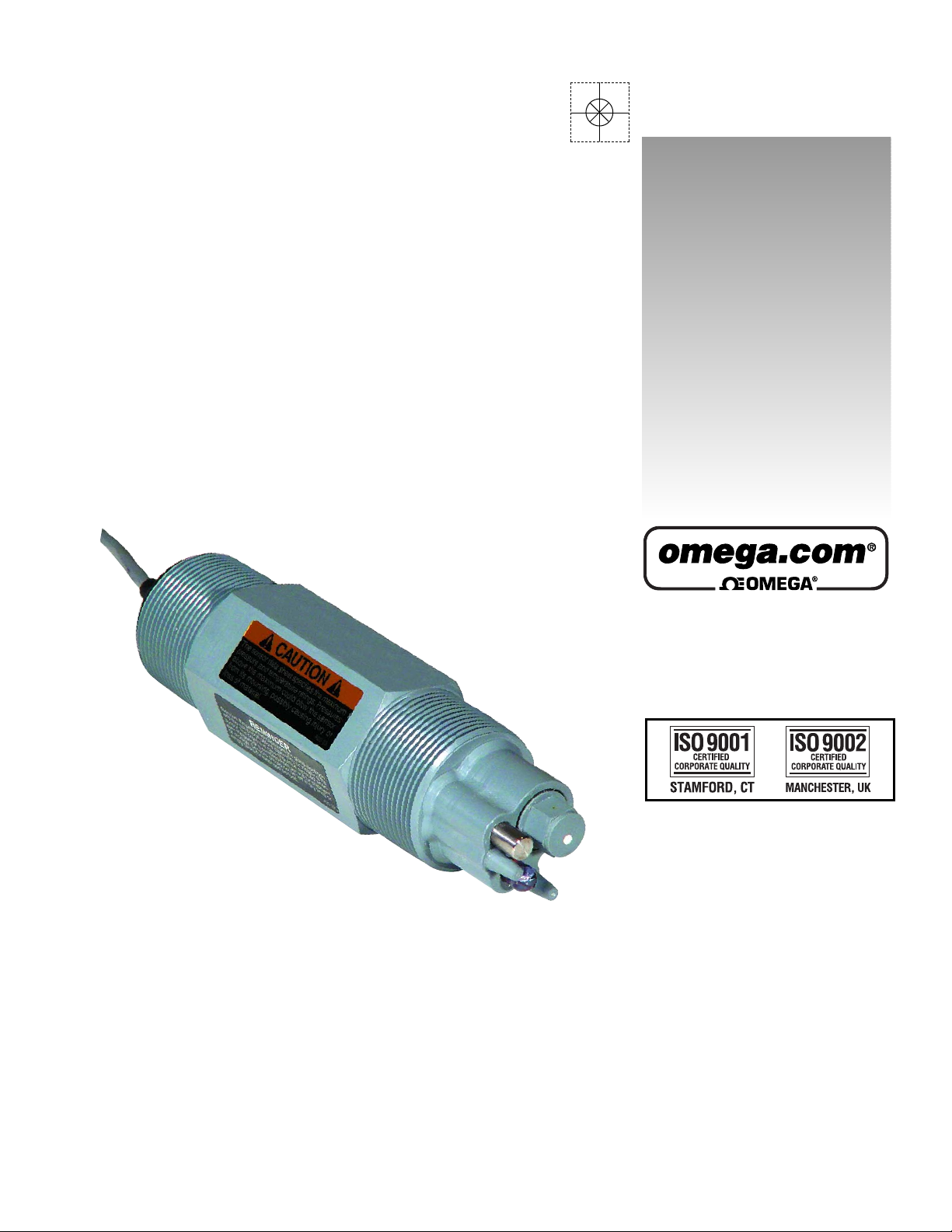
PHE-600/610 ORE-600/610
Differential pH & ORP Probes
Page 2

OMEGAnet®Online Service Internet e-mail
omega.com info@omega.com
Servicing North America:
U.S.A.: One Omega Drive, P.O. Box 4047
ISO 9001 Certified Stamford, CT 06907-0047
TEL: (203) 359-1660 FAX: (203) 359-7700
e-mail: info@omega.com
Canada: 976 Bergar
Laval (Quebec) H7L 5A1, Canada
TEL: (514) 856-6928 FAX: (514) 856-6886
e-mail: info@omega.ca
For immediate technical or application assistance:
U.S.A. and Canada: Sales Service: 1-800-826-6342 / 1-800-TC-OMEGA
Customer Service: 1-800-622-2378 / 1-800-622-BEST
Engineering Service: 1-800-872-9436 / 1-800-USA-WHEN
TELEX: 996404 EASYLINK: 62968934 CABLE: OMEGA
Mexico: En Espan˜ ol: (001) 203-359-7803 e-mail: espanol@omega.com
FAX: (001) 203-359-7807 info@omega.com.mx
®
®
®
Servicing Europe:
Benelux: Postbus 8034, 1180 LA Amstelveen, The Netherlands
TEL: +31 (0)20 3472121 FAX: +31 (0)20 6434643
Toll Free in Benelux: 0800 0993344
e-mail: sales@omegaeng.nl
Czech Republic: Frystatska 184, 733 01 Karviná, Czech Republic
TEL: +420 (0)59 6311899 FAX: +420 (0)59 6311114
Toll Free: 0800-1-66342 e-mail: info@omegashop.cz
France: 11, rue Jacques Cartier, 78280 Guyancourt, France
TEL: +33 (0)1 61 37 2900 FAX: +33 (0)1 30 57 5427
Toll Free in France: 0800 466 342
e-mail: sales@omega.fr
Germany/Austria: Daimlerstrasse 26, D-75392 Deckenpfronn, Germany
TEL: +49 (0)7056 9398-0 FAX: +49 (0)7056 9398-29
Toll Free in Germany: 0800 639 7678
e-mail: info@omega.de
United Kingdom: One Omega Drive, River Bend Technology Centre
ISO 9002 Certified Northbank, Irlam, Manchester
M44 5BD United Kingdom
TEL: +44 (0)161 777 6611 FAX: +44 (0)161 777 6622
Toll Free in United Kingdom: 0800-488-488
e-mail: sales@omega.co.uk
It is the policy of OMEGA Engineering, Inc. to comply with all worldwide safety and EMC/EMI
regulations that apply. OMEGA is constantly pursuing certification of its products to the European New
Approach Directives. OMEGA will add the CE mark to every appropriate device upon certification.
The information contained in this document is believed to be correct, but OMEGA accepts no liability for any
errors it contains, and reserves the right to alter specifications without notice.
WARNING: These products are not designed for use in, and should not be used for, human applications.
Page 3

TABLE OF CONTENTS
1.0 SPECIFICATIONS 2
2.0 INSTALLATION 3
2.1 General Instructions 3
2.2 Submersion Mounting PHE-600/ORE-600 Differential Probes 3
2.3 Submersion Mounting PHE-610/ORE-610 Differential Probes 4
2.4 Flow-through tee mounting PHE-600/ORE-600 Differential Probes 4
2.5 Flow-through tee mounting PHE-610/ORE-610 Differential Probes 4
3.0 SERVICE AND MAINTENANCE 5
3.1 Probe Cleaning 5
3.2 Replacement of Salt Bridge for PHE-600/ORE-600 Differential Probes 5
3.3 Replacement of Salt Bridge for PHE-610/ORE-610 Differential Probes 6
4.0 TROUBLESHOOTING AND SERVICE 7
4.1 Checking 5-wire Differential Probes PHE-600/610 and ORE-600/610 7
5.0 DRAWINGS 8
5.1 N106-154 PHE-600/ORE-600 DIFFERENTIAL PROBES 8
5.2 N106-155 PHE-610/ORE-610 DIFFERENTIAL PROBES 9
5.3 N105-122 INSTALLATION OF PHE-600/ORE-600 DIFFERENTIAL PROBE 10
5.4 N105-123 INSTALLATION OF PHE-610/ORE-610 DIFFERENTIAL PROBES 11
5.5 N106-158 INSTALLATION OF SALT BRIDGE IN A PHE-610/ORE-610 DIFFERENTIAL PROBE 12
Page 1
Page 4

1.0 SPECIFICATIONS
MEASURING RANGES:
pH: 0 to 14.00 pH
ORP: +
WETTED MATERIALS:
PHE-600/610/620: CPVC, ceramic, glass,
ORE-600/610/620: CPVC, ceramic, glass,
TRANSMISSION DISTANCE:
5-wire Probes: 900 meters (3000 ft.)
SENSITIVITY: pH: Less than 0.005 pH
ORP: Less than 0.1mV
STABILITY: 0.03 pH / 2mV per day,
non-cumulative
PRESSURE LIMIT: 100 psig
TEMPERATURE LIMITS: 95°C (203°F)
PROBE CABLE: 15 ft. (4.6 m)
AUTOMATIC TEMPERATURE
COMPENSATION:
-5 to 95°C (23 to 203°F)
2000 mV
titanium palladium alloy and EPDM
titanium palladium alloy, EPDM, and
platinum
Page 2
Page 5

2.0 INSTALLATION
2.1 General Instructions
2.1.1 Specific instructions for each type of probe are given in the following pages.
Common to all probes are the following instructions:
a) If the distance between the probe and the instrument is such that a direct
connection is not possible, the probe cable should be routed to a junction box
with a terminal strip (PHE-600-JB). The box should be well sealed and away
from corrosion danger. Be sure that you have sufficient slack cable to allow for
probe removal for calibration and servicing.
b) Route the interconnect cable from the junction box to the instrument, preferably
in metal conduit. Do not run the power cable or control cables in the same
conduit with the probe interconnect cable.
c) Remove the protective plastic caps from the end of the probe before placing in
service.
d) For best results probes should always be mounted vertically with electrodes
down. If this is not possible, the probe must be at least 15° above horizontal.
2.2 Submersion Mounting PHE-600/ORE-600 Differential Probes
Refer to Dwg# N105-122
2.2.1 a) Apply a thread sealant to the thread on the cable end of the probe and screw a
1-1/2” x 1” NPT reducer onto the probe. Route the sensor cable through an
appropriate length of 1” pipe and using thread sealant, screw the pipe into the
reducer. The cable end of the probe should not be exposed to the process. A
cable strain relief fitting should be used on the upper end of the pipe.
NOTE: An optional protective shroud, Part No. PHE-600-EP should be used on the
electrode end of the probe to protect the electrodes from accidental contact
with the tank bottom, sides or objects in the process.
Page 3
Page 6

2.3 Submersion Mounting PHE-610/ORE-610 Differential Probes
Refer to Dwg# N105-123
2.3.1 a) Install the optional protective shroud, Part No. PHE-610-EP on the probe by
threading the probe cable through it. The shroud will contact the shoulder on
the probe.
b) Install the compression fitting components on the probe in the order shown in
the drawing below so that the pipe thread is towards the cable end of the probe.
If you are concerned that the shroud may get pushed up and expose the
electrodes you can lock it down by the positioning of the fittings.
c) Snug up the nut of the compression fitting to locate it in the desired position.
Hand tighten as much as possible, then turn 1/2 turn with a wrench.
d) Apply a thread sealant to the pipe thread portion of the compression fitting and
screw a 1-1/4” x 1” NPT reducer to it.
e) Route the sensor cable through an appropriate length of 1” pipe and using
thread sealant, screw the pipe into the reducer on the probe. The cable end of
the probe should not be exposed to the process.
2.4 Flow-through tee mounting PHE-600/ORE-600 Differential Probes
Refer to Dwg# N105-122
2.4.1 a) Apply pipe sealant to the electrode end of the probe and screw it into a
standard 1-1/2” NPT tee.
2.5 Flow-through tee mounting PHE-610/ORE-610 Differential Probes
Refer to Dwg# N105-123
2.5.1 a) Take the compression fitting apart. Apply pipe sealant to the 1-1/4” NPT thread
and screw this part into a 1-1/4” tee. A larger tee with an appropriate reducer
may be used.
b) Put the compression fitting components on the probe in the order shown in the
drawing below. They should be in such a position that the electrodes will be in
the pipe stream but not touching the opposite side of the tee.
c) Remove the protective cap from the probe and place the probe in the tee. Now
tighten the nut by hand as much as possible, then turn 1/2 turn with a wrench.
Page 4
Page 7

3.0 SERVICE AND MAINTENANCE
3.1 Probe Cleaning
3.1.1 a) The probe should be kept reasonably clean to avoid measurement errors.
Frequency of cleaning can only be determined by experience. To clean
proceed as follows:
b) Rinse with clean warm water.
c) Soak the end of the probe in warm water and dish detergent for 3 or 4 minutes.
d) Brush the end of the probe, particularly the three electrodes with a soft bristle
brush such as a tooth brush. Take care not to scratch the glass electrode.
e) If the probe is still not clean, it may have to be cleaned with acid. CAUTION:
Do not acid clean probes used in processes containing cyanide solutions.
Some experimentation may be required to determine the most suitable acid for
your process. Use the most dilute acid which is effective. Normally 10 parts of
water to one part muriatic acid is sufficient. Do not use hydrofluoric acid.
f) Soak the probe for not more than 5 minutes in the chosen acid; then rinse
thoroughly with clean warm water and soak in water for 3-5 minutes.
g) Calibrate the system in accordance with the instrument instruction manual.
3.2 Replacement of Salt Bridge for PHE-600/ORE-600 Differential Probes
3.2.1 a) If the system can’t be calibrated after cleaning the probe, it may be necessary
to replace the standard cell solution and the salt bridge. A kit is available for
this purpose (PHE-600-SB). Proceed as follows:
b) Hold the probe vertically with electrodes up. Remove used salt bridge from the
probe using a 9/16”socket-wrench. Turn counter-clockwise, taking care not to
damage the glass electrode. Discard the used salt bridge.
c) Dispose of used solution inside the bridge chamber and flush with pH 7 solution
or distilled water.
d) Refill the chamber with 7pH buffer solution, up to the tip of the electrode, inside
the chamber. DO NOT OVERFILL. It is important to leave space for the salt
bridge thread and a small amount of air.
e) Insert the new salt bridge and tighten using the 9/16”socket wrench until the salt
bridge edging is flush with the probe face.
Page 5
Page 8

3.3 Replacement of Salt Bridge for PHE-610/ORE-610 Differential Probes
3.3.1 a) If the system can’t be calibrated after cleaning the probe, it may be necessary
to replace the standard cell solution and the salt bridge. A kit is available for
this purpose (PHE-612-SB). Proceed as follows:
b) Hold the probe vertically electrodes up. Insert long nose pliers in the blind
holes in the salt bridge and turn counter-clockwise taking care not to damage
the glass electrode. Discard the used salt bridge.
c) Up-end the probe and pour out the contents of the standard electrode chamber.
Flush the chamber with a small amount of pH 7 buffer or clean water.
d) Refill the chamber with 7pH buffer solution, up to the tip of the electrode, inside
the chamber. DO NOT OVERFILL. It is important to leave space for the salt
bridge thread and a small amount of air.
e) Screw the new salt bridge into the cavity until finger tight. Now turn 1/4 turn
with long nose pliers. The front face of the salt bridge should be flush with the
front of the probe.
Page 6
Page 9

4.0 TROUBLESHOOTING AND SERVICE
4.1 Checking 5-wire Differential Probes PHE-600/610 and ORE-600/610
The probe can be checked by a few simple measurements. Two pH buffer solutions, 7 pH
and either 4 pH or 10 pH, and a multimeter are required. For ORP probes two calibration
solutions, 200 and 600 mV, are required. Millivolt solutions may be ±20% of nominal value.
Actual value is noted on the bottle.
4.1.1 PHE-600/610 pH probes
a) Clean the probe as described in Section 4.1. If the system cannot be
calibrated, replace the salt bridge and 7pH buffer solution as described in 4.2.
If the system still can’t be calibrated check the probe as follows:
b) Disconnect red, green, yellow and black wires at the junction box. If you are not
using a junction box, disconnect at the instrument after shutting off the power.
c) Place the probe in 7 pH buffer. Allow enough time for the temperature of the
probe and buffer to stabilize at room temperature.
d) Measure the resistance between the yellow and black wires to check the
probe’s temperature compensator. The resistance should be between 250 and
350 ohms at 25°C. If the resistance is within specifications the probes
thermistor is functioning correctly.
e) Reconnect the yellow and black wires and restore power to the instrument.
f) Measure the voltage between the red and green wires. If it is not within –50 to
+50 millivolts with the probe in 7 pH buffer, the probe is defective. If the voltage
is OK proceed to the next step.
g) Rinse the probe and place it in 4 pH or 10 pH buffer. Allow it to stabilize then
check the voltage again between the red and green wires. If the voltage is
between 100 and 230 millivolts (negative in 10 pH buffer, positive in 4 pH
buffer) the probe is within specifications.
4.1.2 ORP Probes ORE-600/610
a) Rinse the probe and place it in 200 mV solution. The reading should be
between 160 and 240 mV.
b) Repeat the above in a 600 mV solution. The reading should be between 560
mV and 640 mV.
Page 7
Page 10

Page 11

Page 12

Page 13

Page 14

Page 15

WARRANTY/DISCLAIMER
OMEGA ENGINEERING, INC. warrants this unit to be free of defects in materials and workmanship for a
period of
grace period to the normal
ensures that OMEGA’s customers receive maximum coverage on each product.
If the unit malfunctions, it must be returned to the factory for evaluation. OMEGA’s Customer Service
Department will issue an Authorized Return (AR) number immediately upon phone or written request.
Upon examination by OMEGA, if the unit is found to be defective, it will be repaired or replaced at no
charge. OMEGA’s WARRANTY does not apply to defects resulting from any action of the purchaser,
including but not limited to mishandling, improper interfacing, operation outside of design limits,
improper repair, or unauthorized modification. This WARRANTY is VOID if the unit shows evidence of
having been tampered with or shows evidence of having been damaged as a result of excessive corrosion;
or current, heat, moisture or vibration; improper specification; misapplication; misuse or other operating
conditions outside of OMEGA’s control. Components in which wear is not warranted, include but are not
limited to contact points, fuses, and triacs.
OMEGA is pleased to offer suggestions on the use of its various products. However,
OMEGA neither assumes responsibility for any omissions or errors nor assumes liability for any
damages that result from the use of its products in accordance with information provided by
OMEGA, either verbal or written. OMEGA warrants only that the parts manufactured by the
company will be as specified and free of defects. OMEGA MAKES NO OTHER WARRANTIES OR
REPRESENTATIONS OF ANY KIND WHATSOEVER, EXPRESSED OR IMPLIED, EXCEPT THAT OF
TITLE, AND ALL IMPLIED WARRANTIES INCLUDING ANY WARRANTY OF MERCHANTABILITY
AND FITNESS FOR A PARTICULAR PURPOSE ARE HEREBY DISCLAIMED. LIMITATION OF
LIABILITY: The remedies of purchaser set forth herein are exclusive, and the total liability of
OMEGA with respect to this order, whether based on contract, warranty, negligence,
indemnification, strict liability or otherwise, shall not exceed the purchase price of the
component upon which liability is based. In no event shall OMEGA be liable for
consequential, incidental or special damages.
CONDITIONS: Equipment sold by OMEGA is not intended to be used, nor shall it be used: (1) as a “Basic
Component” under 10 CFR 21 (NRC), used in or with any nuclear installation or activity; or (2) in medical
applications or used on humans. Should any Product(s) be used in or with any nuclear installation or
activity, medical application, used on humans, or misused in any way, OMEGA assumes no responsibility
as set forth in our basic WARRANTY/DISCLAIMER language, and, additionally, purchaser will indemnify
OMEGA and hold OMEGA harmless from any liability or damage whatsoever arising out of the use of the
Product(s) in such a manner.
13 months from date of purchase. OMEGA’s WARRANTY adds an additional one (1) month
one (1) year product warranty to cover handling and shipping time. This
RETURN REQUESTS/INQUIRIES
Direct all warranty and repair requests/inquiries to the OMEGA Customer Service Department. BEFORE
RETURNING ANY PRODUCT(S) TO OMEGA, PURCHASER MUST OBTAIN AN AUTHORIZED RETURN
(AR) NUMBER FROM OMEGA’S CUSTOMER SERVICE DEPARTMENT (IN ORDER TO AVOID
PROCESSING DELAYS). The assigned AR number should then be marked on the outside of the return
package and on any correspondence.
The purchaser is responsible for shipping charges, freight, insurance and proper packaging to prevent
breakage in transit.
FOR
WARRANTY RETURNS, please have the
following information available BEFORE
contacting OMEGA:
1. Purchase Order number under which the product
was PURCHASED,
2. Model and serial number of the product under
warranty, and
3. Repair instructions and/or specific problems
relative to the product.
OMEGA’s policy is to make running changes, not model changes, whenever an improvement is possible. This affords
our customers the latest in technology and engineering.
OMEGA is a registered trademark of OMEGA ENGINEERING, INC.
© Copyright 2005 OMEGA ENGINEERING, INC. All rights reserved. This document may not be copied, photocopied,
reproduced, translated, or reduced to any electronic medium or machine-readable form, in whole or in part, without the
prior written consent of OMEGA ENGINEERING, INC.
FOR NON-WARRANTY REPAIRS,
for current repair charges. Have the following
information available BEFORE contacting OMEGA:
1. Purchase Order number to cover the COST
of the repair,
2. Model and serial number of the product, and
3. Repair instructions and/or specific problems
relative to the product.
consult OMEGA
Page 16

Where Do I Find Everything I Need for
Process Measurement and Control?
OMEGA…Of Course!
Shop online at omega.com
TEMPERATURE
MU
Thermocouple, RTD & Thermistor Probes, Connectors, Panels & Assemblies
MU
Wire: Thermocouple, RTD & Thermistor
MU
Calibrators & Ice Point References
MU
Recorders, Controllers & Process Monitors
MU
Infrared Pyrometers
PRESSURE, STRAIN AND FORCE
MU
Transducers & Strain Gages
MU
Load Cells & Pressure Gages
MU
Displacement Transducers
MU
Instrumentation & Accessories
FLOW/LEVEL
MU
Rotameters, Gas Mass Flowmeters & Flow Computers
MU
Air Velocity Indicators
MU
Turbine/Paddlewheel Systems
MU
Totalizers & Batch Controllers
pH/CONDUCTIVITY
MU
pH Electrodes, Testers & Accessories
MU
Benchtop/Laboratory Meters
MU
Controllers, Calibrators, Simulators & Pumps
MU
Industrial pH & Conductivity Equipment
DATA ACQUISITION
MU
Data Acquisition & Engineering Software
MU
Communications-Based Acquisition Systems
MU
Plug-in Cards for Apple, IBM & Compatibles
MU
Datalogging Systems
MU
Recorders, Printers & Plotters
HEATERS
MU
Heating Cable
MU
Cartridge & Strip Heaters
MU
Immersion & Band Heaters
MU
Flexible Heaters
MU
Laboratory Heaters
ENVIRONMENTAL
MONITORING AND CONTROL
MU
Metering & Control Instrumentation
MU
Refractometers
MU
Pumps & Tubing
MU
Air, Soil & Water Monitors
MU
Industrial Water & Wastewater Treatment
MU
pH, Conductivity & Dissolved Oxygen Instruments
M-4178/0805
 Loading...