

Page 1

Table of Contents
Part 1 Introduction
1.1 General 3
1.2 Sensor Features 3
1.3 Sensor Specifications 4
1.4 Important Notes 5
Part 2 Installation
2.1 General 6
2.2 Electrical 8
Part 3 Maintenance and Troubleshooting
3.1 Cleaning the Sensor 10
3.2 Replacing the Saltbridge 11
3.3 Troubleshooting 12
Diagrams and Illustrations
Figure 1-1
Figure 2-1
Monitor/Analyzer 6
Figure 2-2 ORE-45P Sensor Styles 7
Figure 2-3 Cable Description 8
Figure 2-4
ORTX-45 Monitor/Analyzer 9
Figure 3-1
Reference Buffer 11
ORE-45P Sensor Dimensions 5
Integral Mount to ORTX-45
Wiring Diagram, ORE-45P Sensor and
Replacing the Saltbridge and
Rev. C, 05/03
ORE-45P
2
Page 2

Part 1 - Introduction
1.1 General
1.2 Sensor Features
The Model ORE-45P ORP Sensor measures the
oxidation/reduction potential (also known as REDOX) of
aqueous solutions in industrial and municipal process
applications. It is designed to perform in the harshest of
environments, including applications that poison conventional
ORP sensors. All seals are dual o-ring using multiple
sealing materials. The sensor is designed for use with the
Omega ORTX-45 Monitor/Analyzer.
•
A high volume, dual junction saltbridge is utilized to
maximize the in-service lifetime of the sensor. The
annular junction provides a large surface area to minimize
the chance of fouling. Large electrolyte volume and
dual reference junctions minimize contamination of the
reference solution. Saltbridge is replaceable.
• The reference element of the sensor is a glass pH
electrode immersed in a reference buffer solution.
This glass reference system greatly increases the
range of sensor applications.
• An integral preamplifier is encapsulated in the body of
the sensor. This creates a low impedance signal output
which ensures stable readings in noisy environments
and increases the maximum possible distance between
sensor and analyzer to 3,000 feet (914 meters).
• System diagnostics warn the user in the event of
electrode breakage, loss of sensor seal integrity or
integral temperature element failure.
•
Pt1000 RTD. The temperature element used in this
sensor is highly accurate and provides a highly linear
output.
Rev. C, 05/03
ORE-45P
3
Page 3

Part 1 - Introduction 1.3 Sensor Specifications
1.3 Sensor Specifications,
ORE-45P
Measuring Range
Sensitivity
Stability
0.2 mV
2 mV pH per 24 hours, non-cumulative
-1000 to +2000 mV
Wetted Materials PEEK, ceramic, titanium, glass, Viton, platinum or gold,
EDPM (316 stainless steel with 316SS body option)
Temperature Compensation Pt1000 RTD
Sensor Cable 6 Conductor (5 are used) plus 2 shields,
15 feet (4.6 meters) length standard
Temperature Range -5 to 95 °C (23 to 203 °F)
Pressure Range
Maximum Flow Rate
0 to 100 psig
10 feet (3 meters) per second
Max. Sensor-Analyzer
Distance
3,000 feet (914 meters)
Mounting options 1” NPT convertible, 1¼” insertion, 1½” or 2” sanitary style
Weight 1 lb. (0.45 kg)
Notes: 1. The type of hardware used to mount the sensor may limit the maximum temperature
and pressure ratings. Please consult the hardware manufacturer’s specifications
to obtain the relevant temperature and pressure rating information.
2. The maximum flow rate specification is lower for process solutions with low ionic
conductivity or high suspended solids concentration. High flow rates in low ionic
conductivity processes may cause a measurement error due to static electrical
discharge.
Rev. C, 05/03
ORE-45P
4
Page 4
Part 1 - Introduction 1.3 Sensor Specifications
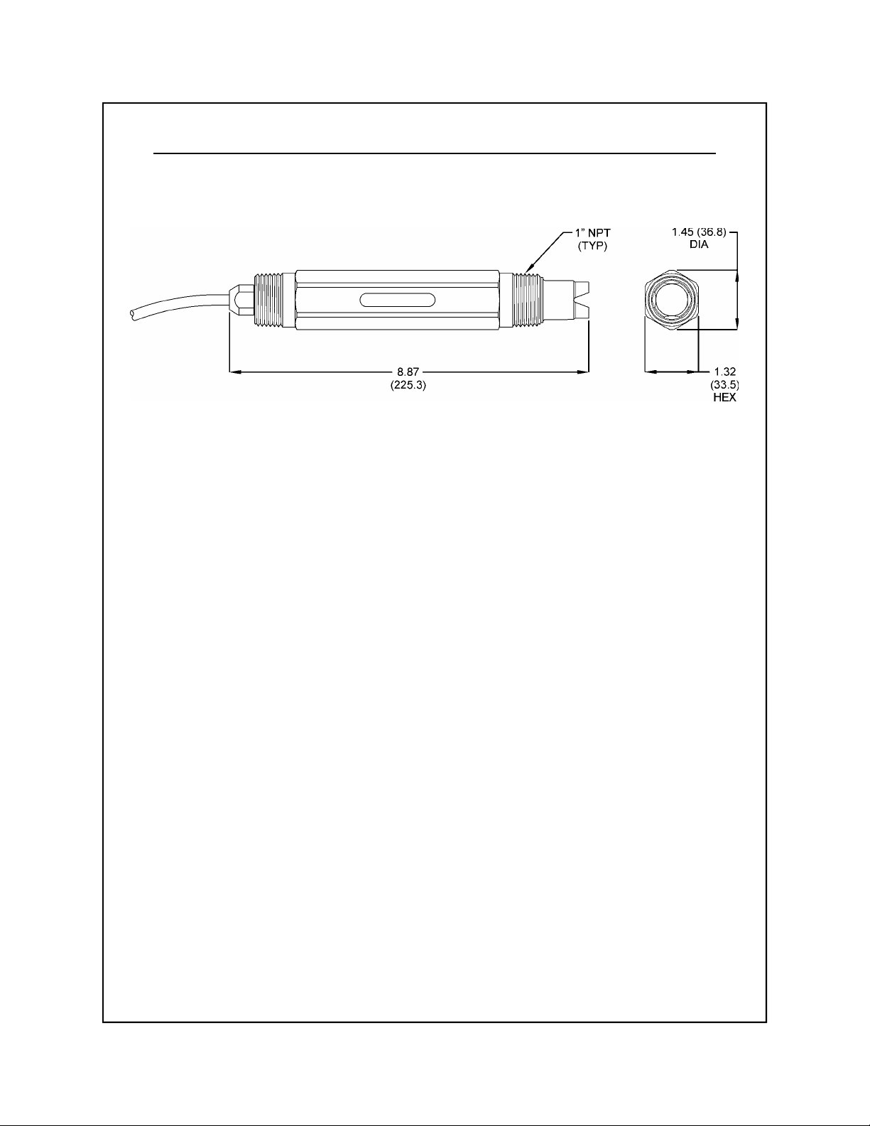
Inches (mm)
Figure 1-1 ORE-45P Sensor Dimensions (standard, convertible-style)
1.4 Important Notes
1. The ORE-45P process electrode contains glass and
can break if not handled properly. Should the electrode
ever break, USE CAUTION when handling the sensor
to avoid serious cuts.
2. The electrode must be wetted at all times to ensure
proper functionality. ORE-45P sensors are shipped
with a fluid-filled cap over the electrode to enable
immediate use (remove cap before installing, save for
storage and shipping). Electrodes that have dried
out for any reason should be hydrated for 24 hours to
restore full functionality.
3. Hydrofluoric acid (HF) will dissolve conventional glass
electrodes. Please contact the factory when the
process application involves this or any other questionable substance.
4. A platinum measuring electrode is standard. However,
DO NOT use platinum electrode in process applications
containing cadmium (Cd), nickel (Ni), tin (Sn), or zinc
(Zn). A gold electrode is available for these applications (contact factory for details).
Rev. C, 05/03
5. Likewise, DO NOT use gold electrode in process
applications containing cyanide (CN-).
ORE-45P
5
Page 5
Part 2 - Installation
2.1 General
The ORE-45P Sensor is designed for industrial and
municipal process applications. Mounting options include
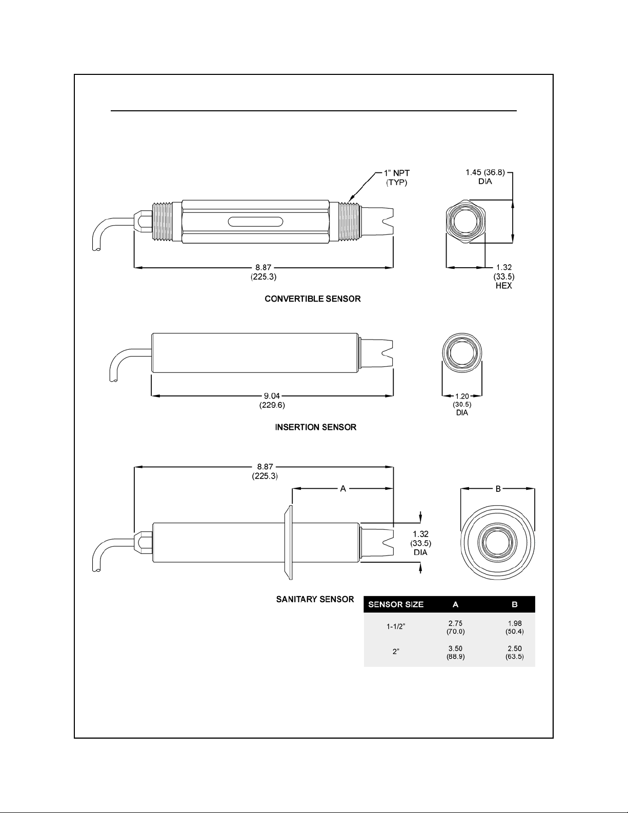
flow-through, submersion, insertion (special hardware
required), or integral mount to the Omega ORTX-45 ORP
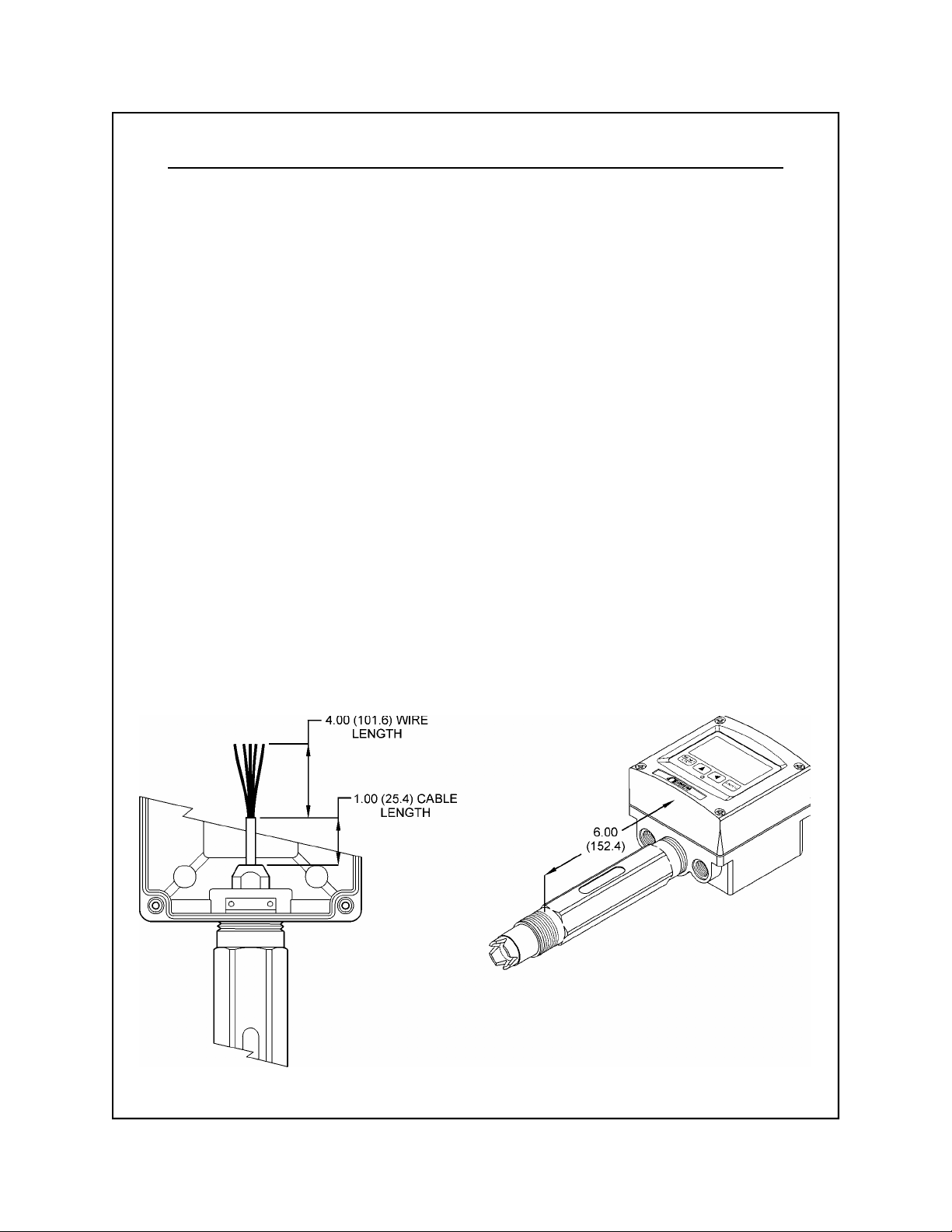
Monitor/Analyzer (see Figures 2-1 and 2-2). The sensor’s
built-in preamp allows sensor-to-analyzer distances of up
to 3,000 feet (914 meters). However, to ensure ease of
calibration, install the transmitter as close as possible to
the sensor.
The sensor should be mounted vertically (electrode face
down) whenever possible. When mounting on an angle,
make sure sensor is at least 10º above horizontal. Do not
mount sensor completely on its side or upside down.
Do NOT use a sealant (e.g., pipe dope) when mounting
the insertion or convertible style sensor. Use industrial/
plumber pipe tape when needed.
Calibrate the sensor before placing it into the process.
See Model ORTX-45 Monitor/Analyzer Instruction Manual for
detailed calibration instructions.
Inches (mm)
Rev. C, 05/03
Note: Integral Mount suitable
for loop-powered version
ONLY
Figure 2-1 Integral Mount to ORTX-45 Monitor/Analyzer
ORE-45P
6
Page 6
Part 2 - Installation 2.1 General
Inches (mm)
Rev. C, 05/03
Figure 2-2 ORE-45P Sensor Styles
ORE-45P
7
Page 7
Part 2 - Installation 2.2 Electrical
2.2 Electrical
The Model ORE-45P has a built-in preamplifier and comes
standard with 15 feet of 6 conductor (only 5 are used)
double shielded cable. The cable is permanently attached
to the sensor, and a PEEK cordgrip is used to seal around
the cable. Nevertheless, the cable should always be kept
as clean and dry as possible.
DANGER
: DO NOT connect sensor cable to power lines.
Serious injury may result.
Take care to route sensor cable away from AC power
lines, adjustable frequency drives, motors, or other noisy
electrical signal lines. Do not run signal lines in the same
conduit as AC power lines. Run signal cable in dedicated
metal conduit if possible. For optimum electrical noise
protection, run an earth ground wire to the ground terminal
in the transmitter.
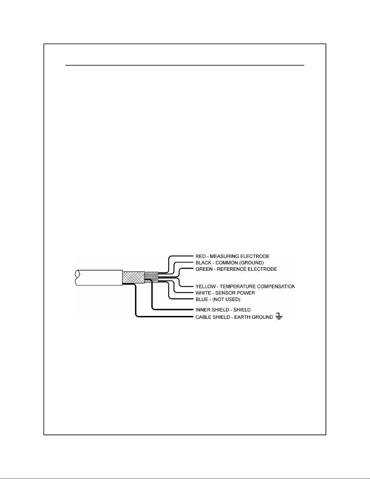
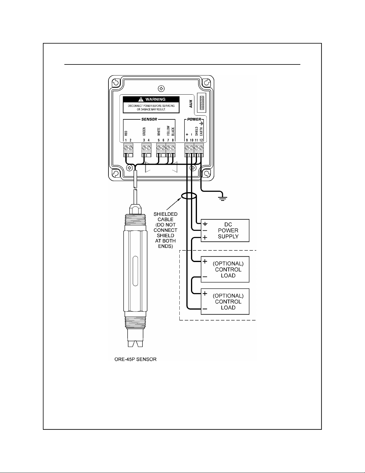
Refer to Figure 2-3 Cable Description and Figure 2-4
Wiring Diagram for illustrative details on electrical installation.
Rev. C, 05/03
Figure 2-3 Cable Description, Model ORE-45P
Note: Only Omega’s custom 6-wire shielded interconnect
cable must be used when connecting the
Model ORE-45P sensor to the analyzer. This
high-performance, double shielded, polyethylene
jacketed cable is specially designed to provide the
proper signal shielding for the sensor used in this
system. No substitutions can be made. Substituted
cables may cause problems with system
performance.
ORE-45P
8
Page 8
Part 2 - Installation 2.2 Electrical
Notes: 1. Voltage between Terminals 9 and 10 MUST be between 16 and 35 VDC.
2. Earth ground into Terminal 12 is optional. This connection can greatly improve
stability in electrically noisy environments.
Figure 2-4 Wiring Diagram, ORE-45P Sensor and ORTX-45 Monitor/Analyzer
Rev. C, 05/03
ORE-45P
9
Page 9

Part 3 - Maintenance and Troubleshooting
3.1 Cleaning the
Sensor
Keep the sensor as clean as possible for optimum
measurement accuracy - this includes both the saltbridge
and the measuring electrode. Frequency of cleaning
depends upon the process solution.
1. Carefully wipe the measuring end of the sensor with a
clean soft cloth. Then rinse with clean, warm
water - use distilled or de-ionized water if possible.
This should remove most contaminate buildup.
2. Prepare a mild solution of soap and warm water. Use a
non-abrasive detergent (such as dishwashing liquid).
NOTES: DO NOT use a soap containing any oils (such
as lanolin). Oils can coat the electrode and
harm sensor performance.
3. Soak the sensor for several minutes in the soap solution.
4. Use a small, extra-soft bristle brush (such as a
mushroom brush) to thoroughly clean the electrode
and saltbridge surfaces. If surface deposits are not
completely removed after performing this step, use a
dilute acid to dissolve the deposits. After soaking, rinse
the sensor thoroughly with clean, warm water. Placing
the sensor in pH 7 buffer for about 10 minutes will help
to neutralize any remaining acid.
Rev. C, 05/03
NOTE: DO NOT soak the sensor in dilute acid solution
for more than 5 minutes. This will help to prevent
the acid from being absorbed into the saltbridge.
WARNING: ACIDS ARE HAZARDOUS.
eye and skin protection when handling. Follow all Material
Safety Data Sheet recommendations. A hazardous
chemical reaction can be created when certain acids come
in contact with process chemicals. Make this determination
before cleaning with any acid, regardless of concentration.
ORE-45P
10
Always wear
Page 10
Part 3 - Maintenance and Troubleshooting 3.2 Replacing the Saltbridge
3.2 Replacing the
Saltbridge
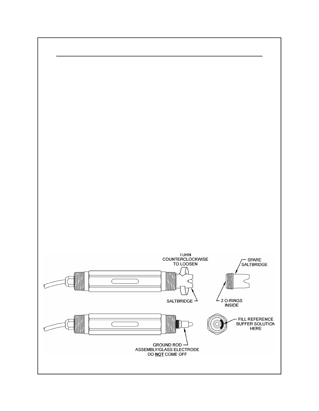
1. Hold the sensor with the process electrode pointing up.
Place a cloth or towel around the saltbridge. Turn the
saltbridge counterclockwise (by hand) to loosen and
remove the saltbridge. Do NOT use pliers.
2. Pour out the old reference buffer by inverting the sensor
(process electrode pointing down). If the reference
buffer does not run out, gently shake or tap the sensor.
3. Rinse the reference chamber of the sensor with deionized water. Fill the reference chamber of the sensor
with fresh Reference Cell Buffer. The chamber holds 6
to 7 mL of solution. MAKE SURE that 6 to7 mL is
used when refilling. The chamber should be FULL.
NOTE: The Reference Buffer Solution, 7.0 pH included
with the saltbridge is NOT typical pH 7 buffer, it is
a special “high-capacity” buffer developed to ensure
the highest possible stability of the reference
portion of the pH measurement. No substitutions
should be made.
4. Inspect the new saltbridge to verify that there are 2
o-rings inside the threaded section of the saltbridge.
Rev. C, 05/03
5. Place the new saltbridge over the ground assembly of
the sensor. Place a cloth or towel around the saltbridge
and hand-tighten the saltbridge by turning it clockwise.
Figure 3-1 Replacing the Saltbridge and Reference Buffer
ORE-45P
11
Page 11

Part 3 - Maintenance and Troubleshooting 3.3 Troubleshooting
Part 3 - Maintenance and Troubleshooting 3.3 Troubleshooting
3.3 Troubleshooting
The first step in resolving any measurement
problem is to determine whether the trouble lies in
the sensor or the transmitter. Since measurement
problems can often be traced to a dirty sensor
electrode and/or saltbridge, cleaning the sensor
using the method outlined in Section 3.1 should
always be the first step in any troubleshooting.
If the sensor cannot be calibrated after cleaning,
replace the saltbridge and reference cell buffer 7
pH as outlined in Section 3.2.
If the sensor still cannot be calibrated, perform
the following test. A multimeter and two millivolt
solutions, at least 100 mV away from each other,
will be needed.
1. With transmitter power on and sensor connected,
place the multimeter’s positive (+) lead on the
white position of the transmitter terminal strip
and the negative (-) lead on the black position.
The multimeter should read between –4.2 and
–6.5 VDC.
Rev. C, 05/03
2. Disconnect the sensor’s red, green, yellow, and
white wires from the transmitter or junction box.
Re-check Step 1.
3. Place the sensor in the first millivolt solution. As in
calibration, allow the temperatures of the sensor
and buffer to equilibrate at room temperature
(approximately 25 ºC).
ORE-45P
12
Page 12

Part 3 - Maintenance and Troubleshooting 3.3 Troubleshooting
Part 3 - Maintenance and Troubleshooting 3.3 Troubleshooting
4. Verify that the sensor’s temperature element
(Pt1000 RTD) is functioning properly by
measuring the resistance between the sensor’s
yellow and black wires. The nominal resistance
value at 25 ºC is 1097 ohms. Use the following
table as a guide to the approximate resistance
value:
ºC RTD Ω
20 1078
25 1097
30 1117
35 1136
5. Reconnect the yellow and white wires.
6. Connect the multimeter’s positive (+) lead to the
red wire and its negative (-) lead to the green
wire. With the sensor in the first millivolt
solution at approximately 20-30 ºC, measure the
DC millivolts. The multimeter should display the
value of the millivolt solution within +100 mV
and –100 mV. If it does not, replace reference
cell buffer and saltbridge (see Section 3.2) and
re-test.
7. With the multimeter connected as in Step 5,
rinse the sensor with clean water and place it in
the second millivolt solution. Allow the
temperatures to equilibrate as before. Check this
solution as in Step 6.
Rev. C, 05/03
ORE-45P
13
 Loading...