

Page 1

8-Channel Wireless Temperature Measurement Module
OM-WLS-TEMP
U 8 Temperature
Input Channels
U Supports Thermocouple
Types J, K, T, E, R, S, B, N,
RTD’s, Thermistors
and Semi-Conductor
Temperature Sensors
U Built-In Cold Junction
Compensation and Open
Thermocouple Detection
U Eight Digital I/O–User
Configuration for Alarms
U 802.15.4 Wireless Protocol
U Range: Up to 46 m (150') Indoors
and 732 m (2400') Outdoors
OM-WLS-TEMP
shown smaller than
actual size.
The OM-WLS-TEMP is a wireless
USB 2.0 full-speed temperature
input module (fully compatible
with both USB 1.1 and 2.0).
The OM-WLS-TEMP provides 8
differential input channels that are
software programmable for different
sensor types including:
• Thermocouple Types J, K, T, E,
R, S, B, N
• RTD–2, 3 or 4-wire Pt100 RTDs
• Thermistors–2, 3 or 4-wire
measurements
• Semiconductor temperature
sensors–LM36 or equivalent
The OM-WLS-TEMP provides
a 24-bit analog-to-digital (A/D)
converter for each pair of differential
analog input channels. Each pair
of differential inputs constitutes a
channel pair. A different type of
sensor (i.e., thermocouple, RTD,
thermistor or semiconductor) can
be connected to each channel
pair, however both channels in
the channel pair need to be the
same sensor type (although if
thermocouples are connected it is
possible to mix thermocouple types).
The OM-WLS-TEMP provides
two integrated cold junction
compensation (CJC) sensors for
thermocouple measurements and
built-in current excitation sources
for resistive sensor measurements,
an open thermocouple detection
feature allows detection of a
broken thermocouple. An onboard
microprocessor automatically
linearizes the measurement data.
The OM-WLS-TEMP features 8
independent temperature alarms.
Each alarm controls an associated
digital I/O channel as an alarm
output. The input to each alarm is
one of the temperature channel
inputs. The output of each alarm
is software configurable as
active high or low. Temperature
threshold conditions are software
programmable to activate each
alarm. When an alarm is activated,
the associated digital I/O channel
is driven to the output state. All
configurable options are software
programmable. The OM-WLS-TEMP
is fully software-calibrated.
The OM-WLS-TEMP can be
operated as a standalone
plug-and-play device which draws
power through the USB cable.
The unit can also be operated
as a remote device that
communicates with the computer
through the OM-WLS-IFC
USB-to-wireless interface device. An
external power supply is shipped with
the device to provide power during
remote operation.
When operating as a remote device,
the OM-WLS-TEMP communicates
with the computer through the
OM-WLS-IFC device connected to
the computer’s USB port. Before the
OM-WLS-TEMP can be operated
remotely, it needs to be connected
to the computer’s USB port and the
network parameters configured to
establish a wireless link with the
interface device. Only devices with
the same parameter settings can
communicate with each other. All
configurable options are software
programmable using the included
InstaCal
LEDs on the OM-WLS-TEMP
indicate the status of communications
over the wireless link. An LED bar
graph shows the fade margin of
signals received by the
OM-WLS-TEMP.
TM
utility software.
To Order, Call or Shop Online at omega.com
SM
1
Page 2
Software
The OM-WLS-TEMP modules ship
with an impressive array of software,
including the new TracerDAQ®, a fullfeatured, out-of-the-box data logging,
viewing, and analysis application.
Driver support and detailed
example programs are included
for Universal Library programming
libraries for Microsoft
Studio® programming languages,
and other languages, including
DASYLab®, and ULx for NI
LabVIEW® (comprehensive library
of Vls and example programs
compatible with 32-bit and 64-bit
LabVIEW v8.5 through 2012) and
InstaCalTM installation, calibration
and test utility-powerful solutions for
programmers and nonprogrammers
alike. These modules operate under
Micrsoft Windows® XP (32-bit only)
and VISTA/7/8 (32-bit and 64-bit)
operating systems.
®
Visual
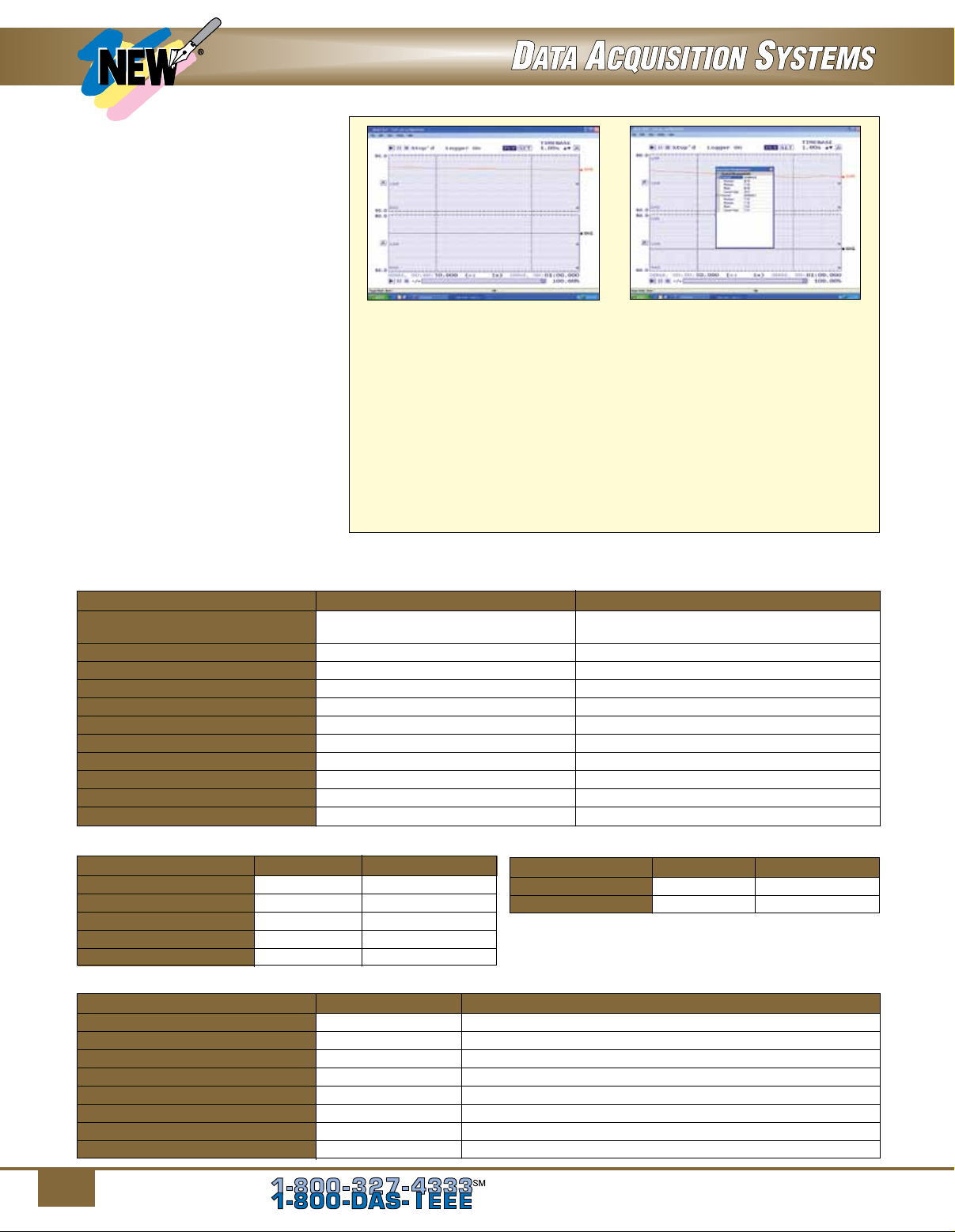
TracerDAQ Strip Chart.
The OM-WLS-TEMP data acquisition module is supplied with TracerDAQTM
software which is a collection of four virtual instrument applications used to
graphically display and store input data and generate output signals:
TracerDAQ Pro Strip Chart
with Measurements.
• Strip Chart—Log and graph values acquire from analog inputs, digital
inputs, temperature inputs and counter inputs
• Oscilloscope—Display values acquired from analog inputs
• Function Generator—Generate waveforms for analog outputs
• Rate Generator—Generate waveforms for counter outputs
SWD-TRACERDAQ-PRO, sold separately is an enhanced version of
TracerDAQ.
TracerDAQ PRO is shown below.
A comparison
of some of the features included in TracerDAQ vs
Features Comparison
Strip Chart
Features TracerDAQ TracerDAQ Pro
Channel Types Analog input, temperature input, Analog input, temperature input,
digital input, event counter digital input, event counter
Number of Channels 8 48
Number of Lanes 2 8
Maximum Samples per Channel 32,000 1 million
Alarm Conditions No Yes
Measurements Window No Yes
Enter Annotations No Yes
Software Triggering No Yes
Hardware Triggering No Yes
Time-of-Day Triggering No Yes
Linear Scaling No Yes
Oscilloscope
Features TracerDAQ TracerDAQ Pro
Channel Type Analog input Analog input
Number of Channels 2 4
Measurements Window No Yes
Reference Channel No Yes
Math Channel No Yes
Function Generator
Features TracerDAQ TracerDAQ Pro
Channel Type Analog output Analog output
Number of Channels 1 16
Waveform Types Sine Sine, square, triangle, flat, pulse, ramp, random, arbitrary
Duty Cycle No Yes
Phase No Yes
Gate Ratio No Yes
Rate Multiplier No Yes
Sweep (Linear and Exponential) No Yes
2
To Order, Call or Shop Online at omega.com
Rate Generator
Features TracerDAQ TracerDAQ Pro
Channel Type Counter output Counter output
Number of Channels 1 20
SM
Page 3

SPECIFICATIONS
ANALOG INPUTS
A/D Converter: Four dual 24-bit
sigma delta A/D converters
Input Isolation: 500 Vdc min
between field wiring and USB
interface
Number of Channels:
8 differential temperature inputs
Differential Input
Voltage Range: Thermocouple,
±0.080V; RTD, 0 to 0.5V; thermistor,
0 to 2V; semiconductor sensor,
0 to 2.5V
Absolute Maximum Input Voltage:
±25V (power on), ±40V (power off)
Throughput Rate: 2 samples/sec
max for all active channels
Input Impedance: 5 GΩ min
Input Leakage Current: 105 nA max
(with open thermocouple detection
enabled)
Normal Mode Rejection Ratio:
90 dB min
Common Mode Rejection Ratio:
100 dB min
Warm-Up Time: 30 minutes max
Thermocouple Input: Software
programmable for type J, K, T, E, R,
S, B, N
Open Thermocouple Detection:
Automatically enabled when
a channel is configured for a
thermocouple sensor
CJC Sensor Accuracy: ±0.25°C
typical, ±0.5°C max (15 to 35°C);
-1.0 to 0.50°C max (0 to 70°C)
Pt100 RTD Input: 2-, 3- or 4-wire
DIN 43760, a = 0.00385, SAMA,
a = 0.003911, ITS-90/IEC751,
a = 0.0038505 (3- or 4-wire
connections take up
2 differential channels)
Thermistor Input: 2-, 3- or 4-wire
standard 2252 through 30,000 Ω
(3- or 4-wire connections take up
2 differential channels)
Semiconductor Sensor:
TMP36 or equivalent
DIGITAL I/O
Digital I/O Channels: 8
Type: CMOS
Configuration: Each DIO bit can be
independently configured for input or
output. Power on reset is input mode
unless bit is configured for alarm
OM-WLS-IFC shown
smaller than actual size.
Pull-Up/Pull-Down
Configuration:
All pins pulled up to 5V via 47 kΩ
resistors (default). Pull-down to
ground (GND) also available
Digital I/O Transfer Rate
(Software Paced):
Digital Input: 50 port reads or
single bit reads per second
(typical)
Digital Output: 100 port writes
Input High Voltage: 2.0V min,
5.5V absolute max
Input Low Voltage: 0.8V min,
-0.5V absolute min
Output High Voltage: 0.7V max
(IOL = 2.5 mA)
Output Low Voltage: 3.8V min
(IOH = -2.5 mA)
Temperature Alarms: 8
(one per digital I/O line)
or single bit writes per second
(typical)
Compatible Thermocouple Input Types
Type Temperature Range Accuracy* (Typical, °C)
-210 to 1200°C (-346 to 2192°F) ±0.507 typ, ±1.499 max (-210 to 0°C)
±0.312 typ, ±0.643 max (0 to 1200
-210 to 1372°C (-346 to 2502°F) ±0.538 typ, ±1.761 max (-210 to 0
±0.345 typ, ±0.691 max (0 to 1372
-200 to 600°C (-328 to 1112°F) ±0.514 typ, ±1.717 max (-200 to 0
±0.256 typ, ±0.713 max (0 to 600
-200 to 1000°C (-328 to 1832°F) ±0.462 typ, ±1.471 max (-200 to 0
±0.245 typ, ±0.639 max (0 to 1000
-50 to 1768°C (-58 to 3214°F) ±0.650 typ, ±2.653 max (-50 to 250
±0.358 typ, ±1.070 max (250 to 1768°C)
-50 to 1768°C (-58 to 3214°F) ±0.648 typ, ±2.491 max (-50 to 250
±0.399 typ, ±1.841 max (250 to 1768°C)
250 to 1820°C (482 to 3308°F) ±0.581 typ, ±1.779 max (250 to 700
±0.369 typ, ±0.912 max (700 to 1820
-200 to 1300°C (-328 to 2372°F) ±0.502 typ, ±1.969 max (-200 to 0
±0.272 typ, ±0.769 max (0 to 1300
Includes cold junction compensation measurement error
*
°C)
°C)
°C)
°C)
°C)
°C)
°C)
°C)
°C)
°C)
°C)
°C)
°C)
To Order, Call or Shop Online at omega.com
SM
3
Page 4

WIRELESS COMMUNICATIONS
Protocol: IEEE 802.15.4,
ISM 2.4 GHz
Range: Up to 150' (50 m) indoor/
urban; up to
1
⁄2 mile (750 m) outdoor
line-of-sight
Transmit Power: 10 mW (10 dBm)
Receiver Sensitivity: -100 dBm (1%
packet error rate)
RF Channels: 12 direct sequence
channels available, channels
12-23 (2.410-2.465 GHz), software
selectable
Addressing: 16-bit PAN (personal
area network) IDs per channel
(software selectable), 64-bit device
address
Encryption: 128-bit AES
(software selectable)
GENERAL
Memory: EEPROM
Microcontroller: Three high-
performance 8-bit RISC
microcontrollers
Power Supply Voltage
(Supplied by USB Port):
4.75V min to 5.25V max
Power Supply Current
(Supplied by USB Port):
500 mA max
User Output Voltage (5V)
4.75V min to 5.25V max,
(connected to self-powered hub)
Wireless Communications
Operation Supply Current: 500 mA
max (ac adaptor required for remote
wireless communications operation)
Excitation Current for Resistance
Sensors: RTD, 210 uA ±5% typ;
thermistor, 10 uA ±5% typ
Isolation: 500 Vdc min measurement
system to PC
SM
OM-WLS-TEMP
shown smaller than
actual size.
USB Device Type:
USB 2.0 (full-speed)
Device Compatibility:
USB 1.1, USB 2.0
USB Cable Length: 3 m (10') max
Dimensions:
127 L x 89 W x 36 mm D
(5.0 x 3.5 x 1.4")
Input Connections:
Screw terminal blocks
(accept 16 to 30 AWG wire)
Operating Temperature:
0 to 50°C (32 to 122°F),
0 to 90% RH non-condensing
Storage Temperature:
-40 to 85°C (-40 to 185°F)
Weight: 180 g (6.4 oz)
RTD Measurement Accuracy
Temperature Range Typ Error (°C) Max Error (°C)
-200 to -150°C (-328 to -238°F) ±2.59 ±2.58
-150 to -100°C (-238 to -148°F)
-100 to 0°C (-148 to 32°F)
0 to 100°C (32 to 212°F)
100 to 300°C (212 to 572°F)
300 to 600°C (572 to 1112°F)
±0.97 ±1.24
±0.31 ±0.58
±0.11 ±0.38
±0.12 ±0.39
±0.12 ±0.40
Thermistor Measurement Accuracy
Thermistor Temperature Range Max Error (°C)
2252Ω -40 to 120°C (-40 to 248°F) ±0.05
3000Ω -40 to 120°C (-40 to 248°F)
5000Ω -35 to 120°C (-31 to 248°F)
10,000Ω -25 to 120°C (-13 to 248°F)
30,000Ω -10 to 120°C (14 to 248°F)
±0.05
±0.05
±0.05
±0.05
Extended Warranty
Program
OMEGACARESM extended warranty program is
available for models shown on this page. Ask
your sales representative for full details when
placing an order. OMEGACARE
labor and equivalent loaners.
To Order Visit omega.com/om-wls-temp for Pricing and Details
SM
covers parts,
Semiconductor Sensor Measurement Accuracy
Sensor Type Temperature Range Max Error (°C)
TMP36 or
equivalent
-40 to 150°C (-40 to 302°F) ±0.05
Model No. Description
OM-WLS-TEMP 8-channel wireless temperature measurement module
OM-WLS-IFC USB-to-wireless interface device (receiver)
SWD-TRACERDAQ-PRO TracerDAQ Pro software
Comes complete with a 2 m (6') USB cable, 100 to 240 Vac ac adaptor with USA plug, Quick Start Guide, Tracer DAQ software,
and operator’s manual on CD.
Ordering Example: OM-WLS-TEMP 8-channel wireless temperature measurement module and OCW-1 OMEGACARESM 1 year extended
warranty adds 1 year to standard 1 year warranty.
4
To Order, Call or Shop Online at omega.com
SM
 Loading...