

Page 1

User’s Guide
http://www.omega.com
e-mail: info@omega.com
OM-USCAN SERIES
Datalogger
1
Page 2

OMEGAnetSM On-Line Service
http://www.omega.com
Internet e-mail
info@omega.com
Servicing
North America:
USA:
ISO 9001 Certified
One Omega Drive, Box 4047
Stamford, CT 06907-0047
Tel: (203) 359-1660
FAX: (203) 359-7700
e-mail: info@omega.com
Canada:
976 Bergar
Laval (Quebec) H7L 5A1
Tel: (514) 856-6928
FAX: (514) 856-6886
e-mail: canada@omega.com
For immediate technical or
application assistance:
USA and Canada:
Sales Service: 1-800-826-6342 /
1-800-TC-OMEGA
Customer Service: 1-800-622-2378 /
1-800-622-BEST
Engineering Service: 1-800-872-9436 /
1-800-USA-WHENSM TELEX: 996404
EASYLINK: 62968934 CABLE: OMEGA
Mexico and Latin America:
Tel: (95) 800-TC-OMEGA
FAX: (95) 203-359-7807
En Espan~ol: (203) 359-1660 ext: 2203
e-mail: espanol@omega.com
SM
SM
SM
2
Page 3

Contents
A
B
C
D
1.
2.
3.
Datalogger Construction 4
Specifications 5
Interface Specification 6
Accuracy of Measurement 7
System Requirements 9
Installing the Software 9
Installing the Datalogger 10
4.8
4.81
4.82
4.821
4.822
4.823
4.83
4.84
4.9
4.91
Single-Channel Graphic 27
Smooth and Zoom 29
Display Mode 30
Trace Settings 31
Axis Settings 31
Examples 32
Inspect 33
Save ASCII 34
Twin-Channel Graphic 35
Mathem. Combinations 36
4.
4.1
4.2
4.3
4.4
4.5
4.6
4.61
4.62
4.63
4.64
4.65
4.7
Software 11
Starting Up the Software 11
Com Port 12
Test & Clear Data 15
Put to Sleep 16
Datalogger Identification 17
Setup 20
Active Sensor 21
External Sensor 21
Sampling Rate 21
Delay 22
Scanning 24
Read Out 25
5.
6.
Troubleshooting 37
Language Editor 38
Index of Key Words 45
3
Page 4
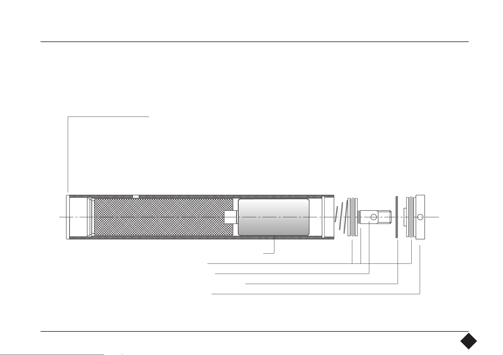
A Datalogger
Construction
Connection socket for interface and external sensors. We recommend that
the protective cap is screwed on to protect the contacts.
Protective Cap
+ Battery -
2/3 AA, 3V lithium battery
O-ring seals
Battery cover
Retaining ring BN823
Cap contents
4
Page 5

B Specifications Internal sensor Precision high-temperature conductor (NTC)
Range: -22°F to 158°F (-30°C to 70°C)
External sensor Precision high-temperature conductor (NTC)
Range: -40°F to 248°F (-40°C to 120°C)
Interchangeability +/- 0.36°F (+/- 0.2°C) in the range from
32°F to 158°F (0°C to 70°C)
Memory depth 64k words, 16 bits
Sampling interval Single-channel: 10 seconds to 20 minutes in 9 steps
Twin-channel: 20 seconds to 40 minutes in 9 steps
Scan Mode: 16 seconds scanning interval
Recording period 3.87 days to 454.5 days
Time base Quartz with ± 5 minutes/year deviation
Interface RS232 with 4800 Baud transmission speed
Data format ASCII or binary (selectable)
5
Page 6

Storage: 2/3 AA lithium battery, replaceable by the user.
Minimum life 2.5 years at 10 sec sampling rate.
In Sleep Mode 9 years (77°F / 25°C)
Recommended battery:
e.g. Sanyo Lithium CR 17335S, 3 V, 1700 mA at 77°F / 25°C
Working range: 32°F to 158°F (0°C to 70°C)
-40°F to 185°F (-40°C to 85°C)
Case: Stainless steel, watertight IP68, up to 10 bar pressure
above atmospheric
Shock: resistance: up to 300 g maximum
C Interface Specification Interface: Connects to PC by 9-channel D-Sub sleeve plug
RS232: Baud rate: 4800 Baud, 8 bits, 1 stop bit, no parity
Scan Mode: 300 Baud. 8 bits, 1 stop bit, no parity
Batteries: 9 V E-Block (IEC: 6F22) alkaline or similar
Battery life 20 hours
Can run from external power source via 9 V universal
power unit regardless of the polarity.
6
Page 7

D Accuracy of Measurement
2.88°
2.16°
1.44°
0.72°
0°
-0.72°
Devation (°F)
-1.44°
-2.16°
-2.88°
-22° - 4°
14° 32° 50° 68° 86° 104° 122° 140° 158° 176° 194° 212°F
Measuring Temperature
7
Page 8
The NTC measuring sensor is accurate to ± 0.36°F (±0.2°C). Due to the negative
temperature coefficients, the resistance increases exponentially at higher temperatures, and consequently even the high resolution of the data transducer is no
longer sufficient to keep consistently to the accuracy of ± 0.36°F (±0.2°C).
The diagram shows how
resolution increases as
temperature rises.
216
180
At -22°F (-30°C), the
resistance is 177kOhm and
at 248°F (120°C) only
144
0.38kOhm. A change of
temperature of 18°F
108
(10°C) at -22°F (-30°C)
Temperature °F
72
causes a change of
resistance of 80kOhm and
36
at 248°F, only 0.057kOhm.
8
Page 9

1. System
Requirements
IBM PC compatible PC 80386/33 or higher with minimum 8 MBytes RAM
(Pentium with 16 MBytes recommended):
- SVGA graphics board, 640x480
- At least 5 MBytes available space on the hard disk
- a free communication port: COM1, COM2, COM3 or COM4 (RS232 port)
- Mouse to run the program easily
- Microsoft Windows 3.1 / Windows 95 / Windows 98 / Windows NT 4.0.
If using Microsoft Windows 3.11, please use the updated "Serial.386 Driver for
Windows/TM for Workgropups Rev. Date 3/94".
2. Installing the
Software
Windows 3.1x:
Start Windows. Open Program Manager and click on "File". In the "File"
window, select "Run ...". Now insert the program floppy disk into drive A or B.
In the "Run ..." command window write "A:setup" or, correspondingly, "B:setup"
and confirm the entry with the "OK" button. If you are not selecting any other
directory, confirm the directory recommended. Installation now proceeds
automatically.
Windows 95 / 98 / NT4.0:
Start Windows. Click on "Start" and choose "Run". Insert floppy disk into drive
A or B. In the "Run" command window write "A:\setup.exe"or "B:\setup.exe"
and confirm the entry with the "Enter" key. If you are not selecting any other
directory, confirm the directory recommended.
Installation now proceeds automatically.
9
Page 10

3. Installing the
Datalogger
The datalogger can only be connected to the computer via the interface
supplied. The interface ensures fast, reliable communication between the
datalogger and the computer and does not take power from the datalogger
battery. Connect the interface to a free Com Port using the cable supplied. Note
the Com Port number to enable you to select it in the software. If your Com Port
has a 25-channel plug, you will need a 25 to 9-pin D-Sub adapter, obtainable from
any computer retailer.
N.B.: When you have connected the interface to the computer, switch the
interface ON. The function is displayed by the red LED. Be sure to switch on the
interface before connecting the datalogger to the interface. If you have already
connected the datalogger by mistake, remove it and reconnect it with the
interface switched on. If you do not follow this sequence, the datalogger
battery is drained unnecessarily and communication between the computer and
the datalogger is not possible. By following the setup sequence described, the
datalogger is switched to its normal state when connected, and is thus ready for
communication. In addition, the datalogger is supplied with power by the
interface to meet the requirements of the interface.
10
Page 11
4. Software
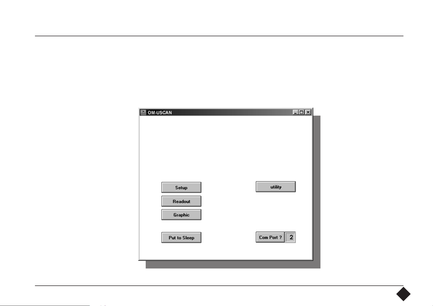
4.1 Starting Up the
Software
When installing the software, the software opens a new program group in your
Windows program with its own icon. Start the software by clicking twice on the
icon. Once the software has been loaded, the software will display the following
opening menu:
µScanT
11
Page 12
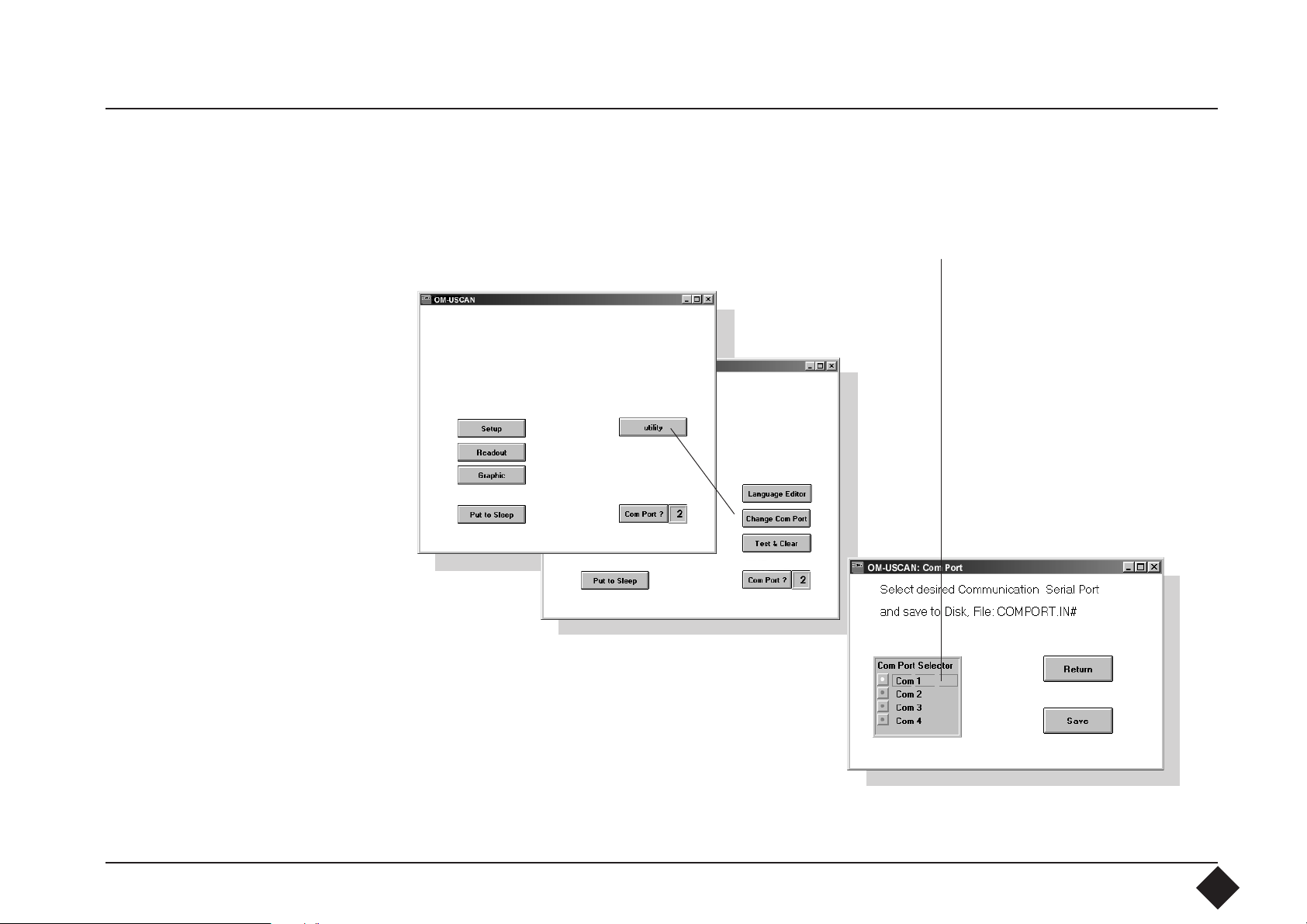
4.2 Com Port
First select the Com Port to which you have connected the interface. To do this,
move the mouse pointer to the appropriate "utility" key. This key will show you
a new key "Change Com Port". Move again the mouse pointer to the "Change
Com Port" key and activate the port by clicking with the mouse.
12
Page 13
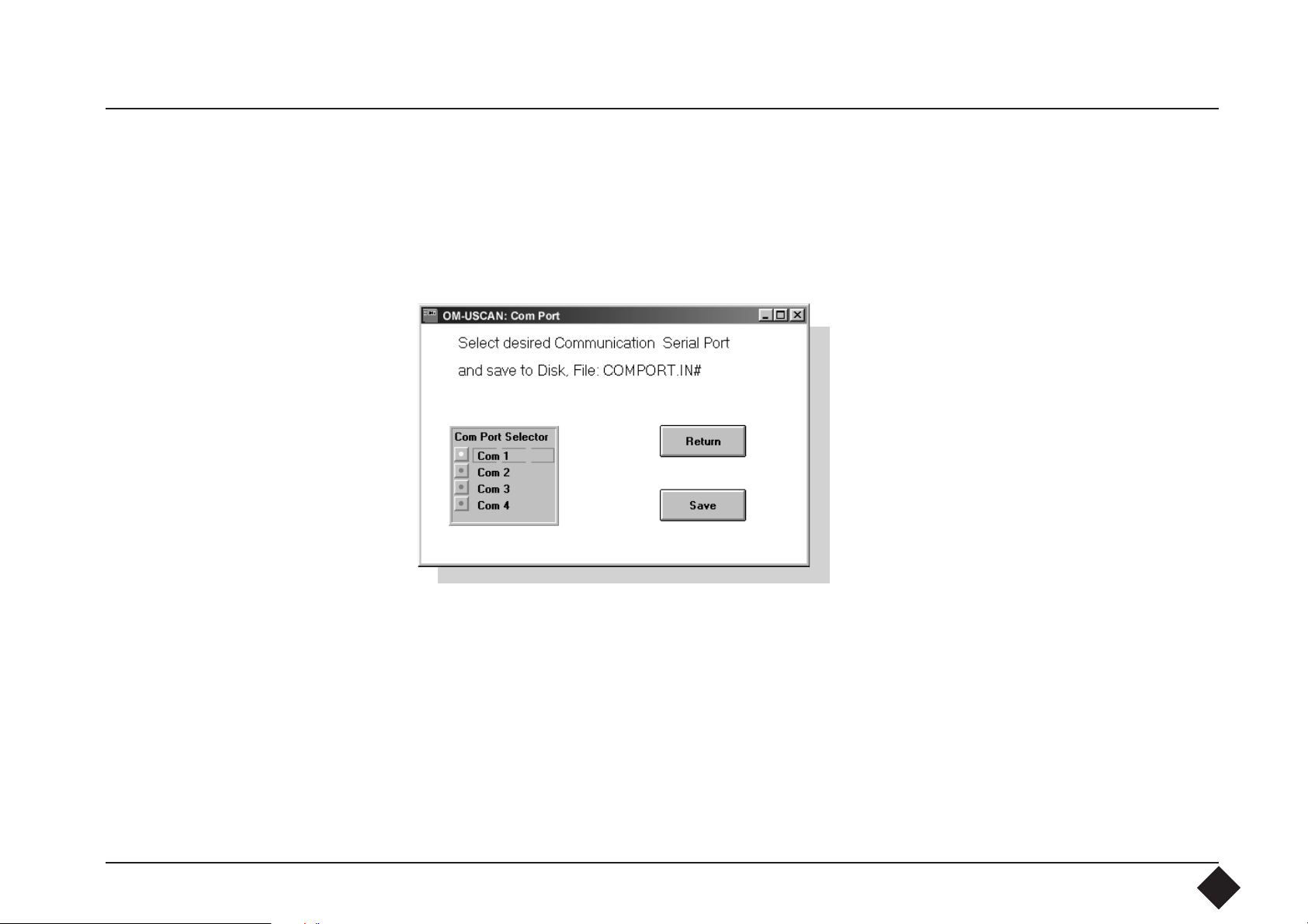
Save the selected Com Port by clicking on the "Save" key.
13
Page 14
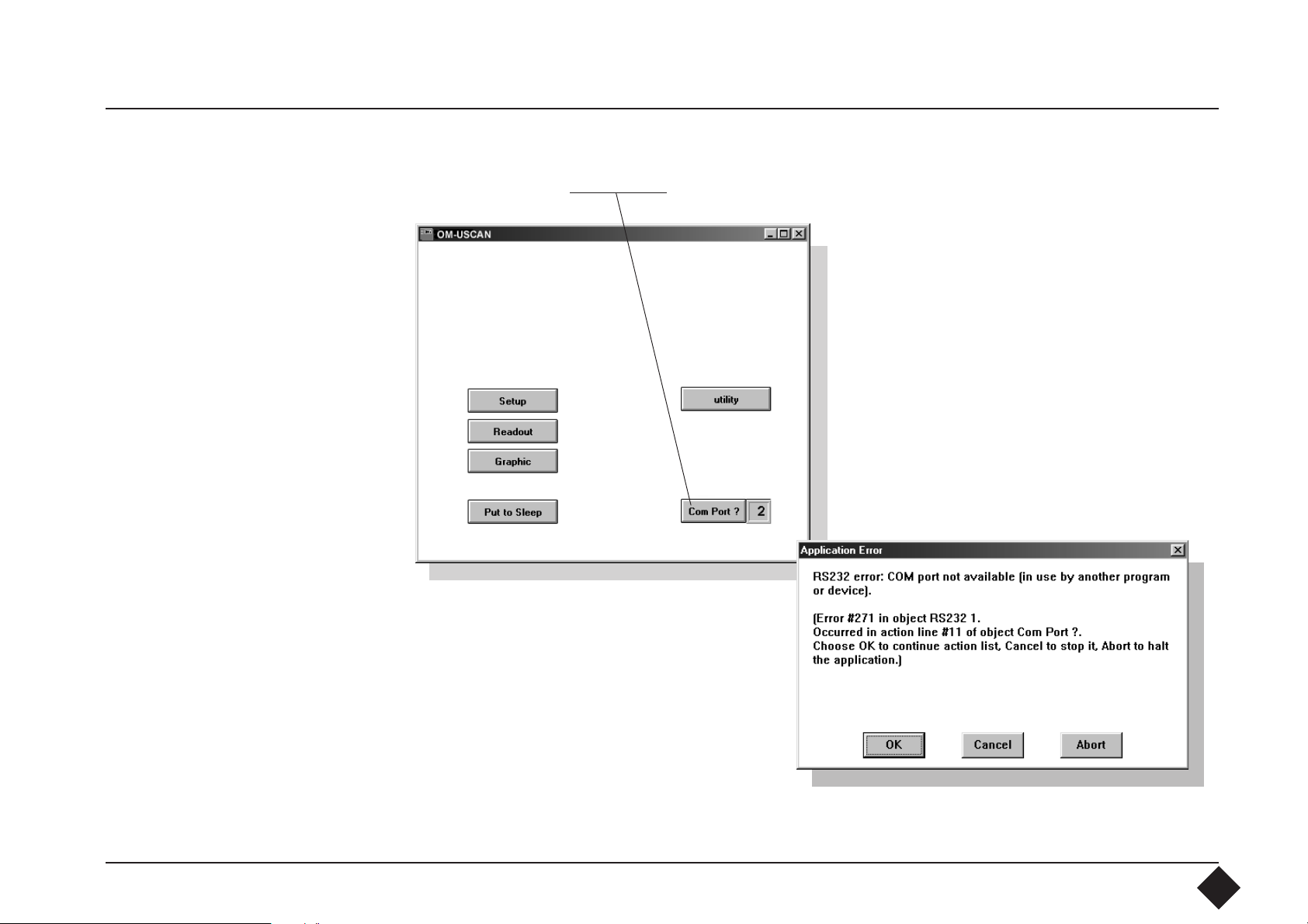
Return to the main window and activate the new Com Port by moving the mouse
cursor to the "Com Port?" key and click on with the mouse.
An error occurs, if the port is in use
by another program or device. Please
repeat the steps again and select the
correct port.
14
Page 15
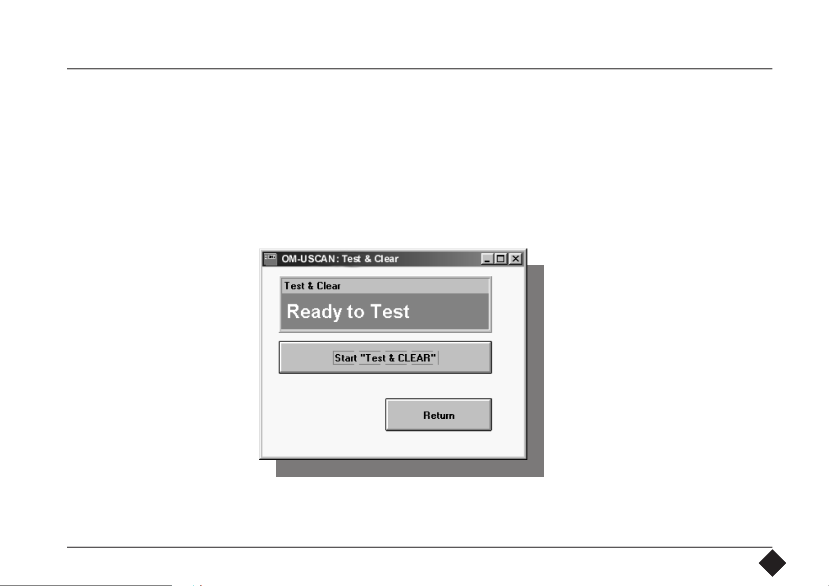
4.3 Test & Clear Data By clicking with the mouse on the “Test & Clear” key, you will start a datalogger
test program, which tests the internal function of the datalogger. This tests and
then clears all the memory cells. Never use this program after capturing data with
the datalogger, because it would then be lost before evaluation. Start the
program by clicking with the mouse on the “Test & Clear” key. The display shows
the test status. Exit the test by clicking on the “Return to Main” key.
15
Page 16
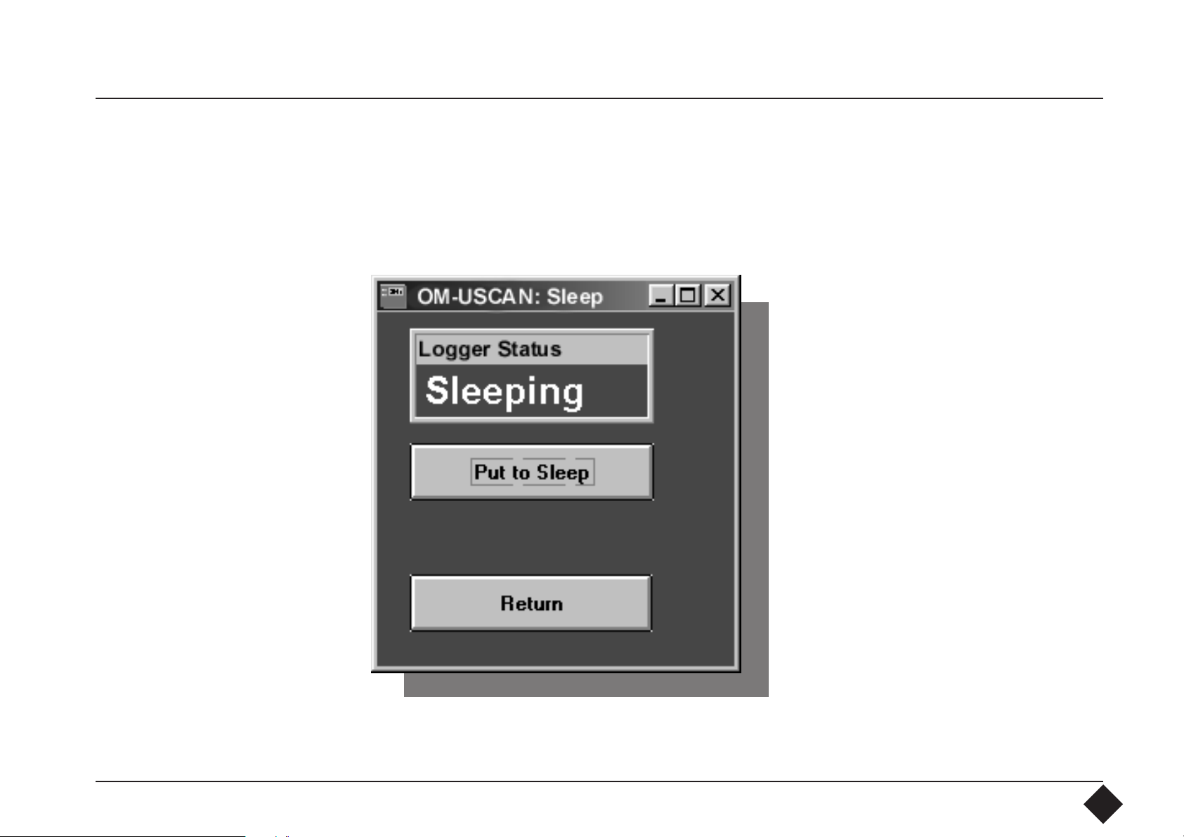
4.4 Put to Sleep If you do not use the datalogger for some time, select the Sleep Mode to conserve
the battery. When in Sleep Mode, the datalogger uses less than 17 µA. Start this
program by activating the “Put to Sleep” key in the Main Menu and pressing this
key again in the Submenu. Then disconnect the datalogger from the interface
and put it aside.
To awake the datalogger again,
reconnect it to the interface. The
connection process reactivates the
datalogger ready for communication.
16
Page 17

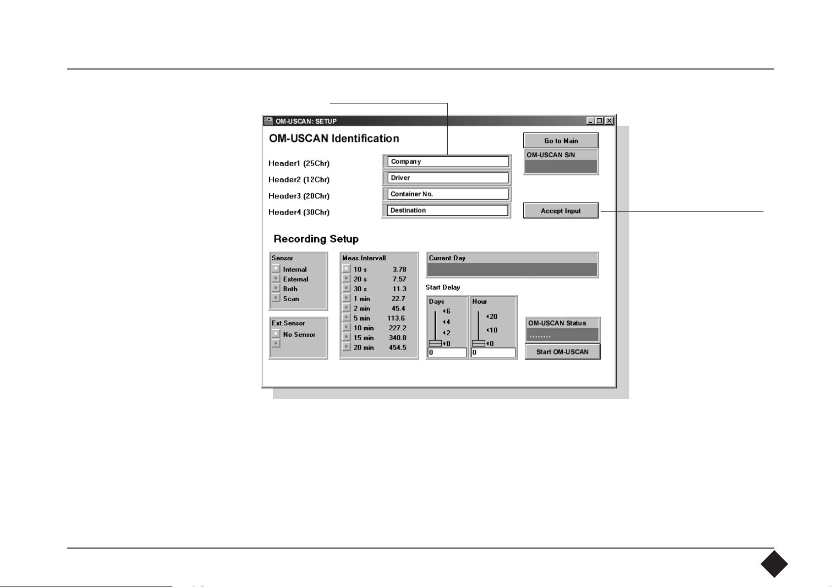
4.5 Datalogger
Identification
To start using the datalogger, the Setup program has to be started. Do this by
clicking with the mouse on the “Setup” key in the Main Menu. This will open the
“OM-USCAN Setup” window. This window contents two parts. One part is the
datalogger identification with the serial number of the datalogger.
17
Page 18

The flexibility of the datalogger software allows you to create your own
application header to indentify after data recording unequivocal your datalogger.
(Please refer to part 6 Language Editor.) As an application example we created a
header as follow:
First line: Company
Second line: Driver
Third line: Container No.
blank fields for data entry
Fourth line: Destination
In the blank field on the
right side you can enter now
your desired infor-mation.
Don´t use the character "&",
this character is used as a
control character and will
terminate any further input.
18
Page 19
Example:
confirm entry
To charge the datalogger with the header information you have to click with the
mouse on the "Accept Input" key. If you start the datalogger without confirmation,
the old header is kept in memory. To test the content of a previous header please
go to the "Readout" menu. This menu will show you the present header. If you like
to keep it unchanged, go directly to the datalogger setup menu without
confirmation by the "Accept Input" key. The software charges now the datalogger
with the data and afterwards reads out the data for correctness test.
19
Page 20

4.6 Datalogger Setup
The second part of the setup window is intended to charge the datalogger
with recording parameters as sampling-time-intervals, kind of sensor used, start
delay and timing mark.
To select the setup
conditions you will
find the corresponding information
under following
items:
4.61 Active
Sensor
4.62 External
Sensor
4.63 Sampling
Rate
4.64 Start Delay in Days
start Hour
20
Page 21

4.61 Active Sensor
The datalogger can operate either with the built-in sensor or an external sensor
or with both sensors in parallel. If data are recorded by two sensors, the memory
capacity is halved and the sampling intervals doubled.
Use the “Active Sensor” window to select whether you want to measure with the
built-in sensor or an external sensor. The external sensor should be connected to
the plug after starting up the datalogger. If you want to measure with both at
once, use the mouse to select the “Both” key.
You will find information about the "Scanning Mode" under 4.65
4.62 External Sensor
4.63 Sampling Rate
If you are working with two sensors at the same time, the “External Sensor”
window will offer “Temperature”.
Use this window to select the measuring interval, i.e. the intervals of time at which
you want to record data. The total recording time (in days) may be read alongside
the Sampling Rate. Measuring can be halted at any time, however.
21
Page 22

4.64 Delay A "Start Delay" can be selected by using the Sliders for "Start Hour" and "Day
Delay". As starting time the next full time period of the indicated actual time will
be used. If you select for example 12 as "Start Hour" and the "Actual Time" is
09:20:54, the "Start Delay" will be 02:39:06. If the value of "Start Hour" is less than
the "Actual Time", no start delay will be added. In this case, 1 day must be added.
Start Hour Start Delay in Days
22
Page 23

Once you have checked all the inputs, the datalogger can be programmed and
started by means of the "Start OM-USCAN" key. To be quite sure that the
communication and start sequence has been successful, the datalogger software
shows you the status of communication and state of the datalogger. When the
datalogger is in measuring mode a window opens and show the "OM-USCAN
Setup confirmation". The display indicates "OK>>>OK>>>OK>>>....". After this
message you can disconnect the
datalogger from the interface.
Note that a reconnection of the
datalogger will cause a reset.
Status message and
"Start OM-USCAN" key
23
Page 24

4.65 Scanning
Direct scanning of data is possible by using an external sensor. In this mode the
datalogger must be connected to the interface and the sensor must be linked up
to the corresponding socket. The scanning program communicates directly to the
datalogger by using a baud rate of 300 baud. The sampling interval is 16 seconds.
Please use the "Scan Stop" switch to halt scanning. The datalogger can be resetted
by reconnection.
24
Page 25

4.7 Read Out
When measuring has been completed or is halted, you can read out the data
by means of this part of the program and store it on hard disk or floppy.
The “Read Out” window gives you details of the datalogger identification, the
recording mode and start of measuring.
25
Page 26

If you want to transfer and store data from the datalogger, click with the mouse on
the “File” key. Give the recorded trace a name under which you will be able to find
it again easily in Graphic. As soon as the PC starts the read out process, the green LED
on the interface lights up, indicating that data are being output by the datalogger.
Data transfer may take up to 10 minutes, depending on the quantity of data. When
the green LED goes out, transfer is completed. You can only proceed the evaluation
by clicking with the mouse on the “Graphic” key.
26
Page 27

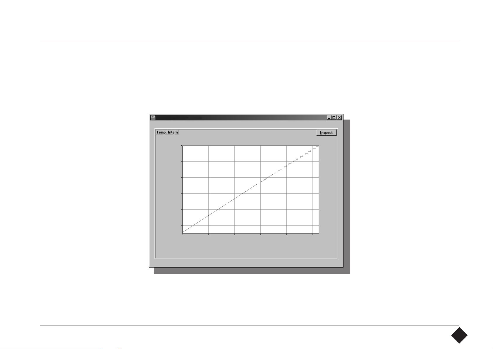
4.8 Single-Channel
“Graphic”
The Graphic program allows you to represent the data stored beforehand
graphically. The main operating features with a single-channel display are shown
in the illustration below. (see 4.8 for two-channel display)
Return to main menu
Call up data file
Convert data to ASCII
More information
“Inspect” graphic
OM-USCAN serial number
Header data
Setup time and date
Start delay
Total recording time
27
Page 28

Click with the mouse on the File window and select a Data File. This may take
some time, depending on the quantity of data. If the raw data have been
linearized, the following screen will appear:
(C)95 by P.T.C AG ,Switzerland
28
Page 29

4.81 Smooth and
Zoom
The Smooth function allows you to smooth the data. This is done by using "n"
points around the actual point to form an average. Use the mouse to move the
slide between n=1 and 100. The smooth function will not be activated until you
call up the data file again. Same worth for the zoom function. Select the zoom
button and the zoom limits as a window and recall the file.
"n" slide
Zoom option with
window limits
29
Page 30

4.82 Display Mode By clicking twice on Graphic you can change various display parameters:
Confirm the changes
Trace display mode
Trace display
Axis display
30
Page 31

4.821 Trace Settings These windows allow you to
change the colour of the axes
and traces and also the grid
interval and trace section.
4.822 Axis Settings
31
Page 32

4.823 Examples
“Bar 1st trace” display
Free choice of axis
32
Page 33

4.83 “Inspect” The “Inspect” window allows you to enlarge and reduce sections.
“File”: print the diagram
“Edit”: export the diagram
“Zoom”: enlarge and reduce
the section
33
Page 34

4.84 “Save ASCII”
This function linearizes the raw data and stores them in ASCII, allowing these data
to be further processed by any programs. The first few lines look like this:
Single-channel Twin-channel
X Y XY1Y2
0.05 5.038
0.053 5.199
0.056 5.362
0.058 5.519
0.061 5.626
0.064 5.764
0.067 5.88
0.069 5.961
0.072 6.035
0.075 6.138
0.078 6.197
0.081 6.243
0.083 6.303
0.086 6.34
0.089 6.37
0.092 6.416
0.094 6.446
0.097 6.469
0.1 6.521
X = time axis in hours
Y = ordinate in °C
0.003 26.234 25.368
0.006 26.396 25.375
0.008 26.485 25.375
0.011 26.567 25.375
0.014 26.567 25.298
0.017 26.485 25.298
0.019 26.485 25.222
0.022 26.485 68.745
0.025 26.508 70.381
0.028 26.59 68.745
0.031 26.598 72.141
0.033 26.688 78.259
0.036 26.793 88.388
0.039 26.922 82.412
0.042 26.412 5.795
0.044 24.61 -4.578
0.047 22.803 -9.084
0.05 20.825 -11.265
0.053 18.91 -12.442
34
Page 35

4.9 Twin-Channel
“Graphic”
If you have recorded data with both, the internal and the external sensor, Graphic
will automatically display them in two separate diagrams. The operating features
are different from those in the single-channel display and mathematical
combinations for the two traces have been added to allow connections to be made
visible.
Operation for
mathematical
combinations.
35
Page 36
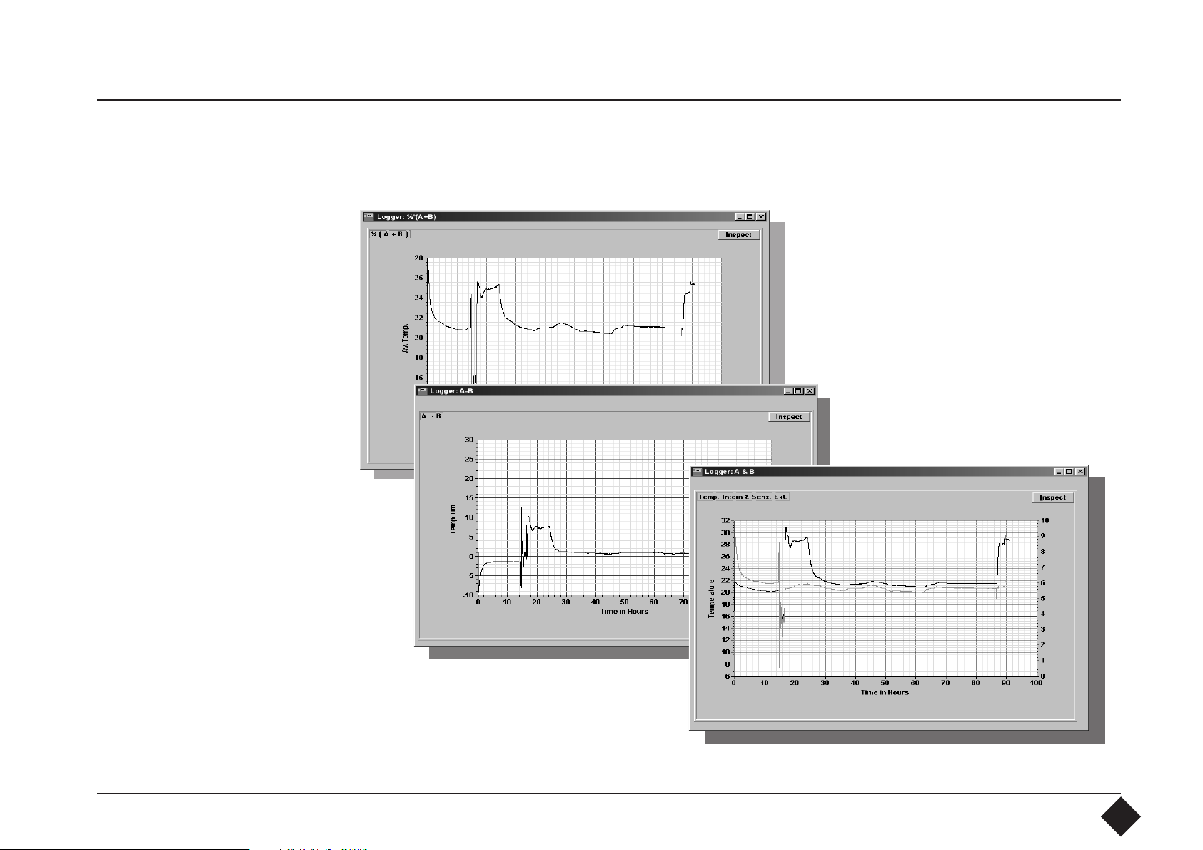
4.91 Mathematical Combinations
Average of the two traces
Superimposed traces
36
Page 37

5. Troubleshooting
Wrong Com Port.
Time Out Delay: 10 seconds
This message appears if the PC cannot communicate with the datalogger.
The reasons may be the following:
- Wrong COM Port selected:
=> check the COM Port
=> check the RS232 cable
- The datalogger is not in communication mode:
=> check if the interface is switched on and reconnect the datalogger
to the interface for resetting.
=> check the 9 Volt Battery of the interface.
37
Page 38

6. Language Editor
The OM-USCAN Software give you the possibility to change the key words in any
window. So you can adapt the program exactly to your needs. The language editor
can only be opened by a protection code in order to prevent any unauthorized and
unintentional manipulation of existing key words. Open the language editor by
the appropriate key word and
confirm by clicking on "Code OK".
A wrong code brings you back to
the main window.
38
Page 39

The right code opens a new window where you can select the window you like
to modify.
39
Page 40

When you open for example the Startup window you can see several blank fields
right of the English key words. In this field you can enter now your desired key
words. Do not terminate your entry by a carriage return, change only with the
mouse to the next field. Blank fields will be displayed in the window as blank. If you
only like to make correction on some fields, please use an ordinary text editor. After
all fields have been labeled, move the mouse cursor to "File".
The data will be saved
under "setscan.in#".
Do not change the file
name.
Now you can test the
setup window by
clicking with the
mouse on the "Return" key in order to
go back to the main
window.
Any text and language can be entered into these fields.
40
Page 41

If you find now any error in the text it is unnecessary to go back to the language
editor and fill out all fields again. A simpler way is to use the editor from Windows.
Change to the Program-Manager and click twice on the "Editor" icon. Open the
directory, where you have installed the OM-USCAN software. Open the file
"setscan.in#".
Now you can modify and correct all text between the " ". Do not clear the" "
control characters. After correction please save the data under same file. Then go
back to the OM-USCAN software and test the changes.
41
Page 42

The language editor is subdivided into the following windows:
Window Use
- Start up Main-Window
- Setup Record Setup the datalogger for data recording
- Readout Readout the recorded data fom datalogger
- Graphic Show the recorded data in a graphic
- Sleep Put datalogger into sleep mode to save power
- Test & Clear Test datalogger communication and function
For each window a separated data file exists. This enables simpler handling of
language data. The relation between the different windows and data files is as
follows:
Window File
- Start up setscan.in#
- Setup Record record.in#
- Readout readout.in#
- Graphic grafic.in#
- Sleep sleep.in#
- Test & Clear t&c.in#
42
Page 43

As you have seen you can modify and correct any OM-USCAN window and
translate to the destination language. The most important window is the setup
window where you can adapt your needs for header. Four lines are available for
the header. If you use the language editor all lines must be filled in. But if you only
like to modify "Header 1" to "Header 4", it´s simpler to use the Windows Editor
to change the four lines.
Header 1
Header 2
Header 3
Header 4
43
Page 44

To modify the four header lines, please open the "record.in#" file.
In this file you see, where the header information is placed:
Header 4
Header 3
Header 2
Header 1
OM-USCAN Identification Company Driver Container No. Destination
OM-USCAN Setup Condition Sensor Interval,External,Both,Scan Mode
Ext. Sensor No Sensor, ;Temperature,Humidity;Ext.only, ; Return
OM-USCAN Serial No. Actual Date/Time Start Delay Days Start Hour
No Delay OM-USCAN Status Waiting Measuring Input O.K. Set Start Delay
Sampl.Interval
Now change with the editor the header info, for example:
OM-USCAN Identification User Name Street City Country
OM-USCAN Setup Condition Sensor Interval,External,Both,Scan Mode
Ext. Sensor No Sensor, ;Temperature,Humidity;Ext.only, ; Return
OM-USCAN Serial No. Actual Date/Time Start Delay Days Start Hour
No Delay OM-USCAN Status Waiting Measuring Input O.K. Set Start Delay
Sampl.Interval
Do not touch any " , ; " . They are used as controlling characters.
Finally save the file and restart the software.
44
Page 45

Index of Key words
A
Accuracy of measurement 7
Active sensor 20, 21
Actual time 22
Awake the Datalogger 16
Axis display 30
Axiss settings 31
B
Batteries 6
Battery 10
Battery cover 4
Blank fields for data entry 18
C
Call up data file 27
Case 6
Change Com Port 12
Character "&" 18
Code 39
Com Port 10, 12
Com Port? 14
Confirm the changes 30
Connection socket 4
Construction 4
Contents 3
Convert data to ASCII 27
Correct all text 41
D
Data format 5
Day delay 22
Delay 22
Difference 36
Direct scanning 24
Display mode 30
Display parameters 30
Driver for Windows 9
E
Editor from Windows 41
Enlarge and reduce the section 33
Export the diagram 33
External Sensor 5, 20, 21
G
Grafic.in# 42
Graphic, grafic.in# 42
Graphic program 27
Grid 31
H
Header 18, 43
Header data 27
Header information 19
I
Identification 25
Input O.K. 19
Inspect 33
Inspect graphic 27
Installing the Datalogger 10
Installing the software 9
Interchangeability of sensor 5
Interface 6
interface light 26
Interface RS232 5
Interface specification 6
Internal sensor 5
L
Language editor 38
M
Manipulation of existing key words 38
Mathematical combinations 35, 36
45
Page 46

Measuring interval 21
Memory 5
Moisture 21
More information 27
O
O-ring seals 4
P
Parameters 30
Polarity 6
Previous header 19
Print the diagram 33
Program manager 9
Protective cap 4
Put to sleep 16
Q
Quartz 5
R
Read out 25
Readout, readout.in# 42
Readout.in# 42
Record.in# 42, 44
Recording period 5
Recording time 21
Resistance 8
Retaining ring 4
RS232 6
S
Sampling interval 5, 21, 24
Sampling Rate 20, 21
Sampling-time-interval 20
Save ASCII 34
Scan mode 5
Scan stop 24
Scanning 24
Select a data file 28
Serial number 17, 27
Serial. 386 driver 9
Setscan.in# 42
Setup 20
Setup record, record.in# 42
Setup time and date 27
Shock 6
Single-channel 5
Single-channel display 27
Single-channel “Graphic” 27
Sleep, sleep.in# 42
Sleep Mode 16
Sleep.in# 42
Smooth and zoom 29
Smooth function 29
Software 11
Specification 5
Start delay 22, 27
Start delay in days 20
Start hour 20, 22
Start up, setscan.in# 42
Starting up the software 11
Status message 23
Storage 6
Strip Chart display 32
Superimpose 36
System requirements 9
T
t&c.in# 42
Temperature 21
Test & clear, t&c.in# 42
Test & clear data 15
Time base 5
Total recording time 27
Trace display 30
46
Page 47

Trace display mode 30
Trace settings 31
Transfer and store data 26
Troubleshooting 37
Twin-channel “Graphic” 35
Twin-channel: 5
U
Universal power unit 6
W
Wrong Com Port 37
Z
Zoom button 29
47
Page 48

48
Page 49

WARRANTY/DISCLAIMER
OMEGA ENGINEERING, INC. warrants this unit to be free of defects in materials and
workmanship for a period of 25 months from date of purchase. OMEGA Warranty adds an
additional one (1) month grace period to the normal two (2) year product warranty to cover
handling and shipping time. This ensures that OMEGA’s customers receive maximum coverage on
each product.
If the unit should malfunction, it must be returned to the factory for evaluation. OMEGA’s
Customer Service Department will issue an Authorized Return (AR) number immediately upon
phone or written request. Upon examination by OMEGA, if the unit is found to be defective it
will be repaired or replaced at no charge. OMEGA’s WARRANTY does not apply to defects
resulting from any action of the purchaser, including but not limited to mishandling, improper
interfacing, operation outside of design limits, improper repair, or unauthorized modification.
This WARRANTY is VOID if the unit shows evidence of having been tampered with or shows
evidence of being damaged as a result of excessive corrosion; or current, heat, moisture or
vibration; improper specification; misapplication; misuse or other operating conditions outside
of OMEGA’s control. Components which wear are not warranted, including but not limited to
contact points, fuses, and triacs.
OMEGA is pleased to offer suggestions on the use of its various products. However,
OMEGA neither assumes responsibility for any omissions or errors nor assumes
liability for any damages that result from the use of its products in accordance with
information provided by OMEGA, either verbal or written. OMEGA warrants only that the
parts manufactured by it will be as specified and free of defects. OMEGA MAKES
NO OTHER WARRANTIES OR REPRESENTATIONS OF ANY KIND WHATSOEVER,
EXPRESSED OR IMPLIED, EXCEPT THAT OF TITLE, AND ALL IMPLIED WARRANTIES
INCLUDING ANY WARRANTY OF MERCHANTABILITY AND FITNESS FOR A
PARTICULAR PURPOSE ARE HEREBY DISCLAIMED. LIMITATION OF LIABILITY: The
remedies of purchaser set forth herein are exclusive and the total liability of OMEGA
with respect to this order, whether based on contract, warranty, negligence,
indemnification, strict liability or otherwise, shall not exceed the purchase price of
the component upon which liability is based. In no event shall OMEGA be liable for
consequential, incidental or special damages.
CONDITIONS: Equipment sold by OMEGA is not intended to be used, nor shall it be used: (1) as a “Basic
Component” under 10 CFR 21 (NRC), used in or with any nuclear installation or activity; or (2) in medical
applications or used on humans. Should any Product(s) be used in or with any
nuclear installation or activity, medical application, used on humans, or misused in any way,
OMEGA assumes no responsibility as set forth in our basic WARRANTY/DISCLAIMER language,
and additionally, purchaser will indemnify OMEGA and hold OMEGA harmless from any liability
or damage whatsoever arising out of the use of the Product(s) in such a manner.
49
Page 50

Where Do I Find Everything I Need for
Process Measurement and Control?
OMEGA...Of Course!
TEMPERATURE
䡺⻬
Thermocouple, RTD & Thermistor
Probes, Connectors, Panels & Assemblies
䡺⻬
Wire: Thermocouple, RTD & Thermistor
䡺⻬
Calibrators & Ice Point References
䡺⻬
Recorders, Controllers & Process Monitors
䡺⻬
Infrared Pyrometers
PRESSURE, STRAIN
AND FORCE
䡺⻬
Transducers & Strain Gauges
䡺⻬
Load Cells & Pressure Gauges
䡺⻬
Displacement Transducers
䡺⻬
Instrumentation & Accessories
FLOW /LEVEL
䡺⻬
Rotameters, Gas Mass Flowmeters
& Flow Computers
䡺⻬
Air Velocity Indicators
䡺⻬
Turbine/Paddlewheel Systems
䡺⻬
Totalizers & Batch Controllers
pH/CONDUCTIVITY
䡺⻬
pH Electrodes, Tester & Accessories
䡺⻬
Benchtop/Laboratory Meters
䡺⻬
Controllers, Calibrators, Simulators
& Pumps
䡺⻬
Industrial pH & Conductivity Equipment
DATA ACQUISITION
䡺⻬
Data Acquisition &
Engineering Software
䡺⻬
Communications-Based
Acquisition Systems
䡺⻬
Plug-in Cards for Apple, IBM
& Compatibles
䡺⻬
Datalogging Systems
䡺⻬
Recorders, Printers & Plotters
HEATERS
䡺⻬
Heating Cable
䡺⻬
Cartridge & Strip Heaters
䡺⻬
Immersion & Band Heaters
䡺⻬
Flexible Heaters
䡺⻬
Laboratory Heaters
ENVIRONMENTAL
MONITORING AND CONTROL
䡺⻬
Metering & Control Instrumentation
䡺⻬
Refractometers
䡺⻬
Pumps & Tubing
䡺⻬
Air, Soil & Water Monitors
䡺⻬
Industrial Water & Wastewater
Treatment
䡺⻬
pH, Conductivity & Dissolved
Oxygen Instruments
M - 3327
50
Page 51

Servicing
Benelux:
Postbus 8034, 1180 LA Amstelveen,
The Netherlands
Tel: (31) 20 6418405 FAX: (31) 20 6434643
Toll Free in Benelux: 06 0993344
e-mail: nl@omega.com
Czech Republic:
Ostravska 767, 733 01 Karvina
Tel: 42 (69) 6311899 FAX: 42 (69) 6311114
e-mail: czech@omega.com
France:
9, rue Denis Papin, 78190 Trappes
Tel: (33) 130-621-400 FAX: (33) 130-699-120
Toll Free in France: 0800-4-06342
e-mail: france@omega.com
It is the policy of OMEGA to comply with all worldwide safety and EMC/EMI regulations that apply. OMEGA is constantly
pursuing certification of its products to the European New Approach Directives. OMEGA will add the CE mark to every
appropriate device upon certification.
The information contained in this document is believed to be correct but OMEGA Engineering, Inc. accepts no liability for any
errors it contains, and reserves the right to alter specifications without notice.
WARNING: These products are not designed for use in, and should not be used for, patient connected applications.
Europe:
Germany/Austria:
Daimlerstrasse 26, D-75392
Deckenpfronn, Germany
Tel: 49 (07056) 3017 FAX: 49 (07056) 8540
Toll Free in Germany: 0130 11 21 66
e-mail: germany@omega.com
United Kingdom: ISO 9002 Certified
• 25 Swannington Road, Broughton Astley,
Leicestershire, LE9 6TU, England
Tel: 44 (1455) 285520 FAX: 44 (1455) 283912
• P.O. Box 7, Omega Drive, Irlam,
Manchester, M44 5EX, England
Tel: 44 (161) 777-6611 FAX: 44 (161) 777-6622
Toll Free in England: 0800-488-488
e-mail: uk@omega.com
RETURN REQUESTS / INQUIRIES
Direct all warranty and repair requests/inquiries to the OMEGA Customer Service Department. BEFORE
RETURNING ANY PRODUCT(S) TO OMEGA, PURCHASER MUST OBTAIN AN AUTHORIZED RETURN (AR)
NUMBER FROM OMEGA’S CUSTOMER SERVICE DEPARTMENT (IN ORDER TO AVOID PROCESSING
DELAYS). The assigned AR number should then be marked on the outside of the return package and on
any correspondence.
The purchaser is responsible for shipping charges, freight, insurance and proper packaging to prevent
breakage in transit.
FOR WARRANTY RETURNS, please have the
following information available BEFORE
contacting OMEGA:
1. P.O. number under which the product was
PURCHASED,
2. Model and serial number of the product
under warranty, and
3. Repair instructions and/or specific problems
relative to the product.
OMEGA’s policy is to make running changes, not model changes, whenever an improvement is possible. This affords our
customers the latest in technology and engineering.
OMEGA is a registered trademark of OMEGA ENGINEERING, INC.
© Copyright 1996 OMEGA ENGINEERING, INC. All rights reserved. This document may not be copied, photocopied, reproduced,
translated, or reduced to any electronic medium or machine-readable form, in whole or in part, without prior written consent
of OMEGA ENGINEERING, INC.
FOR
NON-WARRANTY REPAIRS, consult OMEGA
for current repair charges. Have the following
information available BEFORE contacting OMEGA:
1. P.O. number to cover the COST
of the repair,
2. Model and serial number of product, and
3. Repair instructions and/or specific problems
relative to the product.
51
 Loading...