

Page 1

Where Do I Find Everything I Need for
Process Measurement and Control?
OMEGA…Of Course!
TEMPERATURE
Thermocouple, RTD & Thermistor Probes, Connectors, Panels & Assemblies
Wire: Thermocouple, RTD & Thermistor
Calibrators & Ice Point References
Recorders, Controllers & Process Monitors
Infrared Pyrometers
PRESSURE, STRAIN AND FORCE
Transducers & Strain Gauges
Load Cells & Pressure Gauges
Displacement Transducers
Instrumentation & Accessories
FLOW/LEVEL
Rotameters, Gas Mass Flowmeters & Flow Computers
Air Velocity Indicators
Turbine/Paddlewheel Systems
Totalizers & Batch Controllers
pH/CONDUCTIVITY
pH Electrodes, Testers & Accessories
Benchtop/Laboratory Meters
Controllers, Calibrators, Simulators & Pumps
Industrial pH & Conductivity Equipment
DATA ACQUISITION
Data Acquisition & Engineering Software
Communications-Based Acquisition Systems
Plug-in Cards for Apple, IBM & Compatibles
Datalogging Systems
Recorders, Printers & Plotters
HEATERS
Heating Cable
Cartridge & Strip Heaters
Immersion & Band Heaters
Flexible Heaters
Laboratory Heaters
ENVIRONMENTAL
MONITORING AND CONTROL
Metering & Control Instrumentation
Refractometers
Pumps & Tubing
Air, Soil & Water Monitors
Industrial Water & Wastewater Treatment
pH, Conductivity & Dissolved Oxygen Instruments
M3399/0699
Page 2

OM-LMPLC - User’s Documentation - Omega
User’s Guide
http://www.dasieee.com
e-mail: das@omega.com
OM-LMPLC SERIES
PORTABLE PLC
Page 2 of 47
Page 3

OM-LMPLC - User’s Documentation - Omega
OMEGAnet® On-Line Service Internet e-mail
http://www.omega.com info@omega.com
Servicing North America:
USA: One Omega Drive, Box 4047
ISO 9001 Certified Stamford, CT 06907-0047
Tel: (203) 359-1660 FAX: (203) 359-7700
e-mail: info@omega.com
Canada: 976 Bergar
Laval (Quebec) H7L 5A1
Tel: (514) 856-6928 FAX: (514) 856-6886
e-mail: info@omega.ca
For immediate technical or application assistance:
USA and Canada: Sales Service: 1-800-826-6342 / 1-800-TC-OMEGASM
Customer Service: 1-800-622-2378 / 1-800-622-BESTSM
Engineering Service: 1-800-872-9436 / 1-800-USA-WHENSM
TELEX: 996404 EASYLINK: 62968934 CABLE: OMEGA
Mexico and
Latin America: Tel: (95) 800-826-6342 FAX: (95) 203-359-7807
En Español: (95) 203-359-7803 e-mail: espanol@omega.com
Servicing Europe:
Benelux: Postbus 8034, 1180 LA Amstelveen, The Netherlands
Tel: (31) 20 6418405 FAX: (31) 20 6434643
Toll Free in Benelux: 0800 0993344
e-mail: nl@omega.com
Czech Republic: ul. Rude armady 1868, 733 01 Karvina-Hranice
Tel: 420 (69) 6311899 FAX: 420 (69) 6311114
Toll Free: 0800-1-66342 e-mail: czech@omega.com
France: 9, rue Denis Papin, 78190 Trappes
Tel: (33) 130-621-400 FAX: (33) 130-699-120
Toll Free in France: 0800-4-06342
e-mail: france@omega.com
Germany/Austria: Daimlerstrasse 26, D-75392 Deckenpfronn, Germany
Tel: 49 (07056) 3017 FAX: 49 (07056) 8540
Toll Free in Germany: 0130 11 21 66
e-mail: info@omega.de
United Kingdom: One Omega Drive, River Bend Technology Centre
ISO 9002 Certified Northbank, Irlam, Manchester
M44 5EX, England
Tel: 44 (161) 777-6611 FAX: 44 (161) 777-6622
Toll Free in the United Kingdom: 0800-488-488
e-mail: info@omega.co.uk
__________________________________________________________________________________
_
It is the policy of OMEGA to comply with all worldwide safety and EMC/EMI regulations that apply.
OMEGA is constantly pursuing certification of its products to the European New Approach Directives.
OMEGA will add the CE mark to every appropriate device upon certification.
Page 3 of 47
Page 4

OM-LMPLC - User’s Documentation - Omega
The information contained in this document is believed to be correct, but OMEGA Engineering, Inc.
accepts
no liability for any errors it contains, and reserves the right to alter specifications without notice.
WARNING: These products are not designed for use in, and should not be used for, patient-connected
applications.
WARRANTY/DISCLAIMER
OMEGA ENGINEERING, INC. warrants this unit to be free of defects in materials and workmanship for a period of 13 months from
date of purchase. OMEGA Warranty adds an additional one (1) month grace period to the normal one (1) year product warranty to
cover handling and shipping time. This ensures that OMEGA’s customers receive maximum coverage on each product.
If the unit malfunctions, it must be returned to the factory for evaluation. OMEGA’s Customer Service Department will issue an
Authorized Return (AR) number immediately upon phone or written request. Upon examination by OMEGA, if the unit is found to be
defective, it will be repaired or replaced at no charge. OMEGA’s WARRANTY does not apply to defects resulting from any action of the
purchaser, including but not limited to mishandling, improper interfacing, operation outside of design limits, improper repair, or
unauthorized modification. This WARRANTY is VOID if the unit shows evidence of having been tampered with or shows evidence of
having been damaged as a result of excessive corrosion; or current, heat, moisture or vibration; improper specification;
misapplication; misuse or other operating conditions outside of OMEGA’s control. Components which wear are not warranted,
including but not limited to contact points, fuses, and triacs.
OMEGA is pleased to offer suggestions on the use of its various products. However, OMEGA neither assumes responsibility for any
omissions or errors nor assumes liability for any damages that result from the use of its products in accordance with information
provided by OMEGA, either verbal or written. OMEGA warrants only that the parts manufactured by it will be as specified and free of
defects. OMEGA MAKES NO OTHER WARRANTIES OR REPRESENTATIONS OF ANY KIND WHATSOEVER, EXPRESS OR IMPLIED, EXCEPT
THAT OF TITLE, AND ALL IMPLIED WARRANTIES INCLUDING ANY WARRANTY OF MERCHANTABILITY AND FITNESS FOR A
PARTICULAR PURPOSE ARE HEREBY DISCLAIMED. LIMITATION OF LIABILITY: The remedies of purchaser set forth herein are
exclusive, and the total liability of OMEGA with respect to this order, whether based on contract, warranty, negligence, indemnification,
strict liability or otherwise, shall not exceed the purchase price of the component upon which liability is based. In no event shall
OMEGA be liable for consequential, incidental or special damages.
CONDITIONS: Equipment sold by OMEGA is not intended to be used, nor shall it be used: (1) as a “Basic Component” under 10 CFR
21 (NRC), used in or with any nuclear installation or activity; or (2) in medical applications or used on humans. Should any Product(s)
be used in or with any nuclear installation or activity, medical application, used on humans, or misused in any way, OMEGA assumes
no responsibility as set forth in our basic WARRANTY / DISCLAIMER language, and, additionally, purchaser will indemnify OMEGA and
hold OMEGA harmless from any liability or damage whatsoever arising out of the use of the Product(s) in such a manner.
RETURN REQUESTS / INQUIRIES
Direct all warranty and repair requests/inquiries to the OMEGA Customer Service Department. BEFORE RETURNING ANY PRODUCT(S)
TO OMEGA, PURCHASER MUST OBTAIN AN AUTHORIZED RETURN (AR) NUMBER FROM OMEGA’S CUSTOMER SERVICE DEPARTMENT
(IN ORDER TO AVOID PROCESSING DELAYS). The assigned AR number should then be marked on the outside of the return package
and on any correspondence.
The purchaser is responsible for shipping charges, freight, insurance and proper packaging to prevent breakage in transit.
FOR WARRANTY RETURNS,
please have the following informatio n available BEFORE contacting
OMEGA:
1. Purchase Order number under which
the product was PURCHASED,
2. Model and serial number of the
product under warranty, and
3. Repair instructions and/or specific
problems relative to the product.
OMEGA’s policy is to make running changes, not model changes, whenever an improvement is possible. This affords our customers the latest
in technology and engineering. OMEGA is a registered trademark of OMEGA ENGINEERING, INC.
© Copyright 1999 OMEGA ENGINEERING, INC. All rights reserved. This document may not be copied, photocopied, reproduced, translated, or
reduced to any electronic medium or machine-readable form, in whole or in part, without the prior written consent of OMEGA ENGINEERING, INC.
FOR NON-WARRANTY REPAIRS, consult OMEGA for current repair charges.
Have the following information available BEFORE contacting OMEGA:
1. Purchase Order number to cover the
COST of the repair,
2. Model and serial number of the product, and
3. Repair instructions and/or specific problems
relative to the product.
Table of Contents
TABLE OF CONTENTS...............................................................................................................................................4
TABLE OF FIGURES ....................................................................................................................................................7
TABLE OF TABLES .....................................................................................................................................................7
TABLE OF EXAMPLES ...............................................................................................................................................7
SECTION I - GENERAL INFORMATION................................................................................................................9
Page 4 of 47
Page 5

OM-LMPLC - User’s Documentation - Omega
INTRODUCTION...........................................................................................................................................................9
DESCRIPTION...............................................................................................................................................................9
DOCUMENTATION......................................................................................................................................................9
SAFETY CONSIDERATIONS........................................................................................................................................9
INSTRUMENT IDENTIFICATION...............................................................................................................................9
SECTION II - INSTALLATION................................................................................................................................10
INTRODUCTION.........................................................................................................................................................10
INITIAL INSPECTION ................................................................................................................................................10
POWER REQUIREMENTS..........................................................................................................................................10
BENCH OPERATION..................................................................................................................................................10
PANEL MOUNTING...................................................................................................................................................10
SOFTWARE INSTALLATION ....................................................................................................................................11
SECTION III - OPERATING INSTRUCTIONS .....................................................................................................12
INTRODUCTION.........................................................................................................................................................12
CONTROLS AND INDICATORS .................................................................................................................................12
CONNECTING INPUTS...............................................................................................................................................14
CONNECTING OUTPUTS..........................................................................................................................................15
PROGRAM, RUN, AND PAUSE MODES....................................................................................................................16
RESETTING THE COUNTERS AND PROCEDURE ...................................................................................................17
OM-LMPLC DISPLAYS.............................................................................................................................................17
PROGRAMMING OVERVIEW.....................................................................................................................................19
STEP COMMANDS.....................................................................................................................................................19
Overview...............................................................................................................................................................19
Turn Outputs “On/Off”......................................................................................................................................20
Turn Outputs “On” .............................................................................................................................................20
Turn Outputs “Off”.............................................................................................................................................21
Waiting for Inputs to be “On”..........................................................................................................................21
Waiting for Inputs to be “Off”..........................................................................................................................22
Wait.......................................................................................................................................................................22
End Test................................................................................................................................................................22
Pause Test............................................................................................................................................................22
Jump if Inputs are “On”....................................................................................................................................23
Jump if inputs are “Off”.....................................................................................................................................23
Increase counters................................................................................................................................................23
Count inputs........................................................................................................................................................24
Begin Loop...........................................................................................................................................................25
End Loop..............................................................................................................................................................26
Jump......................................................................................................................................................................26
PROCEDURE WRITER PROGRAMMING SO FTWARE .............................................................................................26
Starting Procedure Writer................................................................................................................................26
Creating a new procedure ................................................................................................................................27
Different Views of your procedure...................................................................................................................27
The Step view.......................................................................................................................................................27
The Sheet View....................................................................................................................................................28
The Output view..................................................................................................................................................29
Editing the custom displays..............................................................................................................................30
Custom Input, Output, and Counter names...................................................................................................31
Modifying onboard counts...............................................................................................................................32
Procedure Writer Options.................................................................................................................................32
Testing your Input and Output wiring............................................................................................................33
Debugging your Procedure..............................................................................................................................34
Printing your procedure...................................................................................................................................34
Documenting your procedure..........................................................................................................................34
Page 5 of 47
Page 6

OM-LMPLC - User’s Documentation - Omega
Saving your procedure......................................................................................................................................35
Opening your procedure...................................................................................................................................35
Reading a Procedure from the OM-LMPLC ..................................................................................................35
Using the procedure Wizard.............................................................................................................................36
OM-LMPLC FIELD PROGRAMMER........................................................................................................................36
Downloading the OM-LMPLC field programmer software into the calculator.....................................37
ADVANCED PROGRAMMING TECHNIQUES ...........................................................................................................38
INTEGRATING THE OM-LMPLC IN A DATA ACQUISITION SYSTEM ..............................................................39
SECTION IV - PRINCIPLES OF OPERATION.....................................................................................................40
INTRODUCTION.........................................................................................................................................................40
STEP CYCLES.............................................................................................................................................................40
SOLID STATE RELAYS.............................................................................................................................................41
SECTION V - MAINTENANCE .................................................................................................................................42
INTRODUCTION.........................................................................................................................................................42
OUTPUT FAILURE .....................................................................................................................................................42
TROUBLESHOOTING.................................................................................................................................................42
SECTION VI - SUPPORT..........................................................................................................................................43
INTRODUCTION.........................................................................................................................................................43
INTERNET WEB SITE...............................................................................................................................................43
APPENDICES...............................................................................................................................................................44
SPECIFICATIONS .......................................................................................................................................................44
SERIAL CABLE WIRING............................................................................................................................................45
RS232 PROTOCOL SUMMARY..................................................................................................................................45
PROCEDURE WRITER - L ICENSE AGREEMENT ....................................................................................................47
Page 6 of 47
Page 7

OM-LMPLC - User’s Documentation - Omega
Table of Figures
FIGURE 1 - OM-LMPLC FRONT PANEL .....................................................................................................................12
FIGURE 2 - REAR OF OM-LMPLC...............................................................................................................................13
FIGURE 3 - OM-LMPLC INPUT CIRCUIT ...................................................................................................................14
FIGURE 4 - TYPICAL OM-LMPLC INPUT WIRING...................................................................................................15
FIGURE 5 - OM-LMPLC OUTPUT CIRUIT FOR AC AND DC...................................................................................15
FIGURE 6 - TYPICAL OM-LMPLC DC OUTPUT WIRING ........................................................................................16
FIGURE 7 - TYPICAL OM-LMPLC AC OUTPUT WIRING........................................................................................16
FIGURE 8 - RESETTING PROCEDURES “COUNT DOWN” WARNING ON THE LCD DISPLAY..............................17
FIGURE 9 - RESETTING PROCE DURES WITH "PROCEDURE" RESET MESSAGE.....................................................17
FIGURE 10 - OUTPUT 2 ACTIVATED AND INPUT 1 ACTIVATED ..........................................................................18
FIGURE 11 - COUNTERS 1-2 DISPLAY .........................................................................................................................18
FIGURE 12 - PROCEDURE INFORMATION DISPLAY..................................................................................................18
FIGURE 13 - PROCEDURE WRITER STEP V IEW........................................................................................................28
FIGURE 14 - SHEET V IEW.............................................................................................................................................29
FIGURE 15 - OUTPUT V IEW.........................................................................................................................................30
FIGURE 16 - E NTERING CUSTOM DISPLAYS..............................................................................................................31
FIGURE 17 - NAMING INPUTS, OUTPUTS, AND COUNTERS....................................................................................31
FIGURE 18 - E DIT CURRENT COUNTS DIALOG..........................................................................................................32
FIGURE 19 - SELECTING A COMM PORT AND OTHER PROCEDURE WRITER OPTIONS.....................................33
FIGURE 20 - TESTING INPUT AND OUTPUT WIRING SCREEN ................................................................................34
FIGURE 21 - READ THE PROCEDURE OUT OF THE PLC TO PRINT IT OUT ..........................................................35
FIGURE 22 - THE MAIN TOOLBAR FOR THE FIELD PROGRAMMER IS ACCESSED THROUGH THE CST BUTTON
.................................................................................................................................................................................36
FIGURE 23 - THE OM-LMPLC FIELD PROGRAMMER ALLOWS PROGRAMMING WITHOUT THE PC................37
FIGURE 24 - SERIAL CABLE WIRING...........................................................................................................................45
Table of Tables
TABLE 1 - SUMMARY OF STEP COMMANDS.............................................................................................................20
TABLE 2 - OM-LMPLC TROUBLE SHOOTING...........................................................................................................42
Table of Examples
All examples are included on the Procedure Writer install disks. Their names are indicated by (filename) in
the following table.
EXAMPLE 1 - TURNING OUTPUTS ON AND OFF WITH THE "OUTPUTS ON/OFF" COMMAND
(EX_ONOFF.LM1)..................................................................................................................................................20
EXAMPLE 2 - RUNNING PARTS WHEN SE LECTED ONLY USING THE TURN OUTPUTS ON COMMAND
(EXTURNON.LM1).................................................................................................................................................21
EXAMPLE 3 - USING INPUTS TO MONIT OR TEST PROGRESS WITH THE WAIT INPUTS COMMAND
(EXWAITIN.LM1)..................................................................................................................................................22
EXAMPLE 4 - RUNNING TWO DIFFERENT TESTS WITH ONE PROCEDURE USING JUMPIF COMMAND
(EXJUMPIN.LM1)...................................................................................................................................................23
EXAMPLE 5 - USING COUNTERS TO TRACK CYCLES (EX_CNTR.LM1)..................................................................23
EXAMPLE 6 - COUNTING INPUTS DIRECTLY WITH THE "COUNT INPUTS" COMMAND (EX_CNTIN.LM1)...24
EXAMPLE 7 - USING "JUMP IF" COMMANDS FOR MORE ADVANCED INPUT COUNTING (EXTCNTIN2.LM1).25
EXAMPLE 8 - USING LOOPS TO CYCLE A SPECIFIC NUMBER OF TIMES (EXLOOP1.LM1)..................................25
Page 7 of 47
Page 8

OM-LMPLC - User’s Documentation - Omega
EXAMPLE 9 - USING MULTIPLE LOOPS FOR HANDLING USER INSPECTIONS (EXLOOP2.LM1).........................26
EXAMPLE 10 - CREATING OR LOGIC WITH MULTIPLE JUMP STEPS....................................................................38
EXAMPLE 11 - IMPLEMENTING AND LOGIC WITH MULTIPLE JUMP STEPS......................................................39
Page 8 of 47
Page 9

OM-LMPLC - User’s Documentation - Omega
Section I - General Information
Introduction
This section gives a general overview on the OM-LMPLC.
Description
The purpose of the OM-LMPLC is to function as a flexible I/O controller for test labs. In contras t with
widely available controllers, the OM-LMPLC was specifically designed for on/off cycling tests such as
pneumatic cycling, electronic power cycling, and other durability testing. Being tailored to the particular
niche market brings features not availa ble on current PLC's. Features usually required for testing such as
cycle counters, ease of use, computer control, and solid state relay outputs.
Documentation
The User’s Documentation is the comprehensive source for information concerning the OM -LMPLC. Use
the Table of Contents, Table of Figures, and Table of Tables to quickly locate the information you require.
Other sources of information include the Procedure Writer’s on-line documentation, the Omega WWW
(World Wide Web) site, and Omega’s Application notes.
Safety Considerations
Although the OM -LMPLC is a low voltage device, the OM-LMPLC could control potentially dangerous test
setups. The OM -LMPLC is not designed for controlling in situations where errors in the control logic could
cause human injury. Please use common sense in your use of the OM -LMPLC and apply standard safety
practices.
Qualified personnel should only perform wiring. Extreme care should be taken when working with dangerous
voltage levels.
When output errors could cause problems, for example if a Solid State Relay fails “On”, it is recommend that
the user installs a output disable circuit on each of the commons of the output connector. OM -LMPLC’s
output enable button on its front panel disables the outputs from the control side only, so if the Solid State
Relay fails “On” the output enable button will not have any affect.
Instrument Identification
On the rear of the OM-LMPLC is an identification number. This label clearly identifies the serial and model
number of the OM-LMPLC.
Page 9 of 47
Page 10

OM-LMPLC - User’s Documentation - Omega
Section II - Installation
Introduction
This section shows how to get started using the OM -LMPLC. This includes initial components inspection,
mounting, installing the programming software, and configuring your PC’s communications port.
Initial Inspection
When you receive your OM-LMPLC, you should have the following:
• Power supply (or) power jack connector
• Serial cable
• Setup disks (2) for the Procedure Writer Software (included in this manual)
• OM-LMPLC
• OM-LMPLC User's Documentation
• Panel mount slides (or) rubber feet and handle
If you do not have any of the above, please contact Omega’s.
Power requirements
The OM-LMPLC comes with its own wall transformer DC power supply or a power jack connector
compatible with the input power connector on the OM-LMPLC. The power jack connector allows you to use
an alternative DC power source. Consult the Specifications in the appendices for information on power
requirements.
Bench Operation
The OM -LMPLC is suitable for bench top operation. However, care should be taken when using the OMLMPLC for controlling dangerous AC voltages. It is recommended that you enclose the OM -LMPLC in a
protective case when working with AC voltages.
Panel Mounting
You can install the OM-LMPLC into a panel. In order to install the OM-LMPLC into a panel, you can use the
panel mount installation kit. Contact Omega’s for more information.
Page 10 of 47
Page 11

OM-LMPLC - User’s Documentation - Omega
Software Installation
Use the two disks included with the OM-LMPLC to install the “Procedure Writer” software. The following
steps describe the installation process.
1. Insert the program disk into a floppy disk drive.
2. Choose “Run” from the file menu of Program Manager if you are using Windows 3.x. If you are using
Windows 95, press start and choose run.
3. Type the drive letter followed by a colon, slash ( \ ) and then “setup”. For example, if you placed the
disk into the “a” drive it would be “a: \setup.exe”
4. Press enter.
5. Follow the instructions as shown in the setup program. The setup will check to see if there is enough
space on your hard drive, install the software, and allow you to choose the directory for locating the
software.
Setting up a free Comm port
Most PCs, both laptop and desktop type, have two Comm ports. Many devices use Comm ports to get data
into and out of your PC. Two of the most prominent devices are mice and modems. Most desktop PCs have
a mouse connected to one of their Comm ports. Most Laptops have a mouse built in which does not use the
external Comm port connector. You must determine which Comm port is not in use. See Setting up a Comm
port on page 32 for more information.
Page 11 of 47
Page 12
OM-LMPLC - User’s Documentation - Omega
Section III - Operating Instructions
Introduction
This section describes how to operate the OM-LMPLC. It includes information about the hardware, software
features, and the OM-LMPLC step commands.
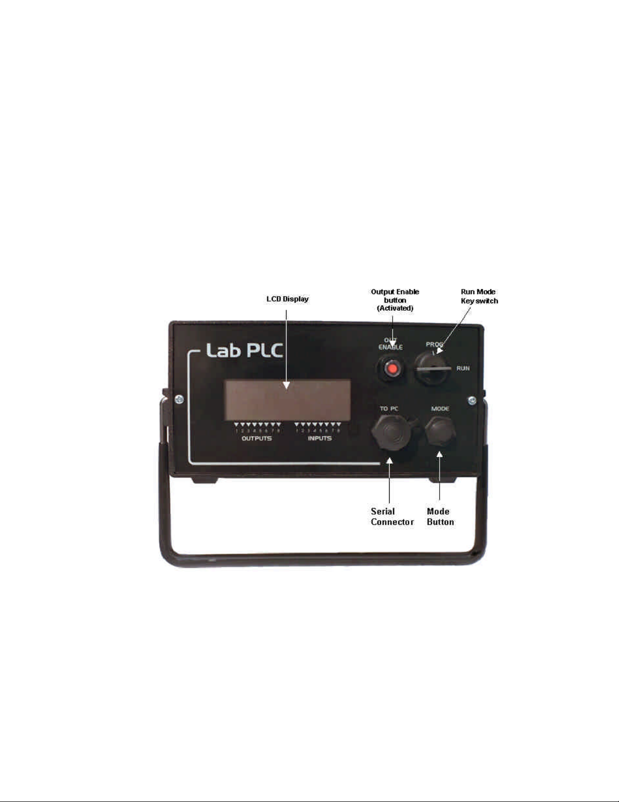
Controls and Indicators
In order to simplify use and reduce cost, the OM -LMPLC’s front panel user interface is extremely simple.
The front panel of the OM -LMPLC has only two buttons, a key-switch, a connector, and a display (Figure
1). The rear panel has connections for the Inputs, Outputs, and the device power. All user interactions occur
through the front panel.
Figure 1 - OM -LMPLC front panel
The Mode push button is used to select the currently viewed display, to remove the OM -LMPLC from
“Pause Mode”, and to reset the procedure and internal counters. The operatio n of the “Mode” button is
defined in the “Program, Run, and Pause Modes” sub-section later in this section.
Page 12 of 47
Page 13
OM-LMPLC - User’s Documentation - Omega
The key-switch selects the operational mode of the OM -LMPLC. The OM-LMPLC has three modes: Pause,
Run, and Programming Mode. The sub-section called “Program, Run, and Pause Modes” clearly defines the
interaction of the key-switch and the different modes.
The output enable push button controls the signal to the OM -LMPLC’s internal hardware output chip that
enables its outputs. The purpose for this switch is so you can quickly disable the outputs. For increased
safety, the output enable switch is independent of the Microprocessor control. When this switch is
depressed, it will show an orange dot. In this state, it will enable the Microprocessor to control the outputs.
Note: The "output enable" safety feature only disables the outputs from the control side. For example, if the
solid state relay failed on (Shorted) this switch would have no effect. For possible dangerous situations an
external shut of f relay should be added on the power side.
The serial connector is where you connect the serial cable with the PC. This is how the OM-LMPLC
communicates with the PC.
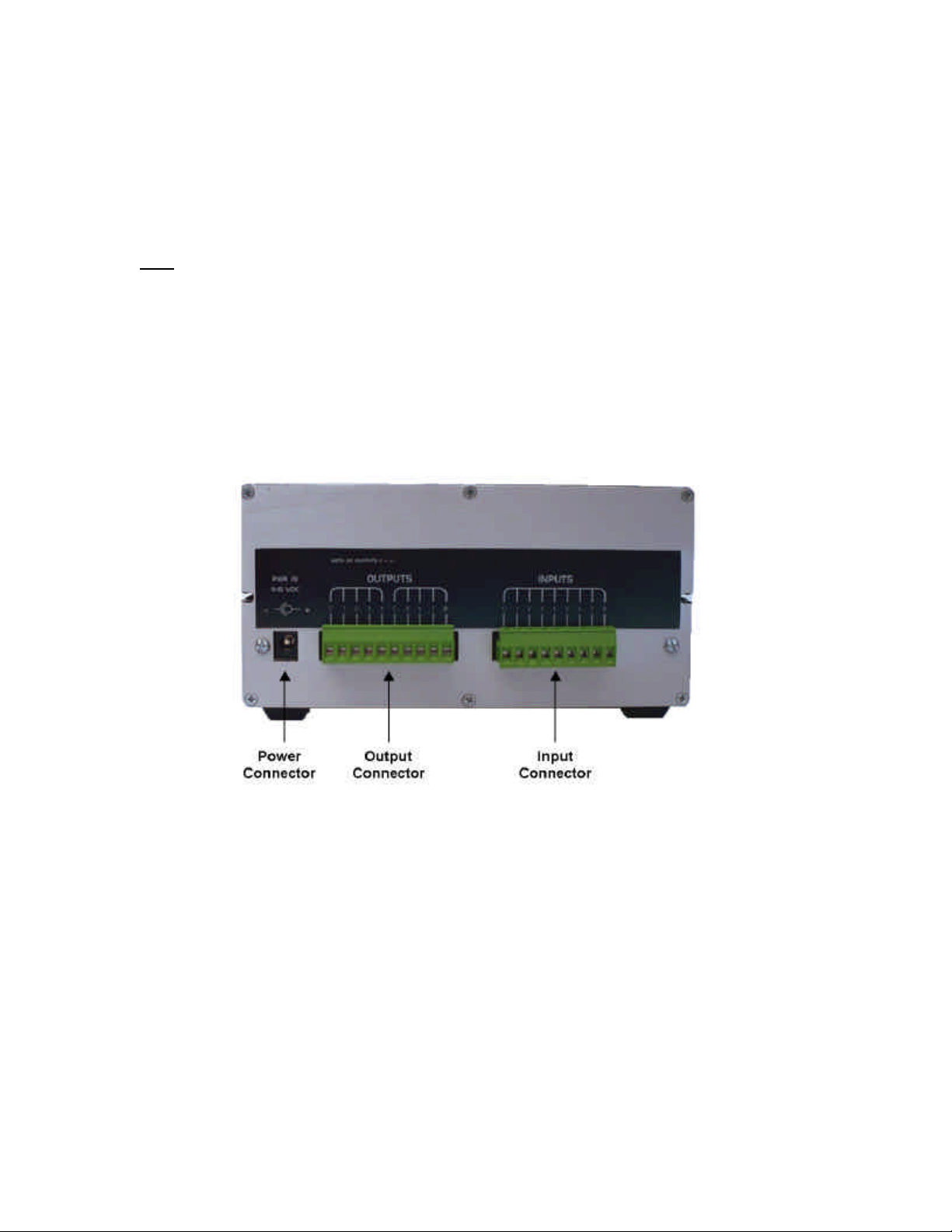
The back panel of the OM-LMPLC has the connectors for the outputs, inputs, and power (Figure 2).
Figure 2 - Rear of OM -LMPLC
The power connector is where the proper power source should be connected. This connector has positive
at its center and ground on the outside. Consult specifications for power requirements.
The OM -LMPLC output connector is a ten-position connector. It has two commons located at position 1
and 5. Outputs one through four share position 1 common and outputs four through eight share position 5.
For example connection diagrams see the “Connecting Outputs” sub section later in this section.
The OM -LMPLC input connector is a nine-position connector. Position 1 of the connector is a common to
all eight inputs. For more information on connecting inputs to the OM-LMPLC, see sub-section called
“Connecting Inputs” later in this section.
Page 13 of 47
Page 14
OM-LMPLC - User’s Documentation - Omega
LEDs
DC
Voltage
DC
Sensor
Supply
Input (X)
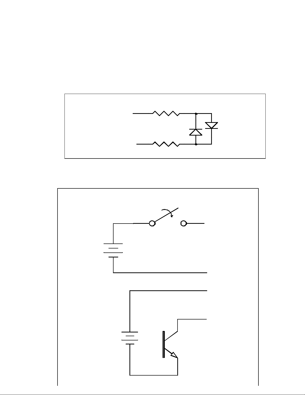
Connecting Inputs
The inputs on the OM-LMPLC are bi -directional LED opto-isolators (Figure 3). You can use any DC voltage
source from 5 to 35 VDC to power the LED to complete the circuit. Wiring for dry contact switches and
transistor output type devices (such as proximity sensors and photo detectors) are shown in
Figure 4.
Input (X)
Input
Common
Figure 3 - OM -LMPLC Input Circuit
Dry Contact Switch
5-35 V
Common
Common
Input (X)
Transistor Output
5-35 V
Page 14 of 47
Sensor such as
Proximity Sensor
or Photo Detector
Page 15
OM-LMPLC - User’s Documentation - Omega
-
Figure 4 - Typical OM -LMPLC Input Wiring
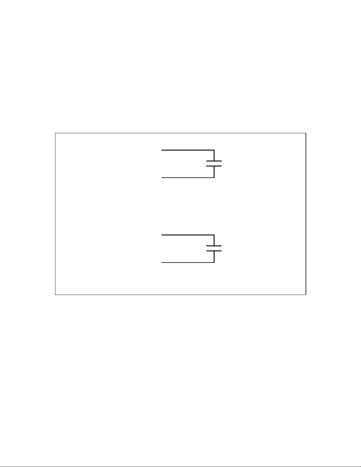
Connecting Outputs
The OM-LMPLC has a 10-position connector for outputs. Outputs are available for DC and AC. Typical
wiring for DC and AC connections is shown in
Figure 6 and Figure 7, respectively.
Output (X)
Crydom Solid
State Relay AC
Type (SCR or
Common (X)
C1=OUT 1-4
C2=OUT 5-8
TRIAC)
Output (X)
Common (X)
C1=OUT 1-4
C2=OUT 5-8
Figure 5 - OM -LMPLC output ciruit for AC and DC
Crydom Solid
State Relay DC
Type (Bipolar
Transistor) Note
polarity
Page 15 of 47
Page 16

OM-LMPLC - User’s Documentation - Omega
DC Voltage
1 AMP
3-60V
Figure 6 - Typical OM -LMPLC DC Output wiring
DC Load such as
solenoid, relay or
DUT.
Output (X)
Common
AC Load such as a
solenoid, relay or
DUT.
Fuse
120 VAC (Neutral)
120 VAC (Hot)
Figure 7 - Typical OM -LMPLC AC Output wiring
Output (X)
Common
Program, Run, and Pause Modes
The OM -LMPLC operates in three different modes. The modes are the Run mode, Pause mode, and Program
mode. For each mode, the OM-LMPLC behaves differently. The function of the “Mode” button also
changes depending on what operational mode the OM -LMPLC is in. The key-switch is used to change the
operational mode of the OM-LMPLC.
Page 16 of 47
Page 17

OM-LMPLC - User’s Documentation - Omega
When the key-switch is placed in to the “Prog” position, the OM -LMPLC enters program mode. Moving
the switch to the run position places the OM -LMPLC into pause mode. Run mode is then entered from
pause mode by pressing the “Mode” button. In this case, the “Mode” effectively acts as a start button.
The OM -LMPLC will power-up in pause mode if the key-switch is set to the “run” position. This avoids
accidentally running a program on power up.
The program mode is where the OM-LMPLC is programmed and reset. In progra m mode, the “Mode”
button serves two functions. First, pressing the mode button immediately switches to the next display. If
the “Mode” button is held pressed, the OM-LMPLC will begin the reset countdown. See the next section for
more information on rese tting.
Pause mode serves as a temporary mode between the Program and Run mode. In the run mode, the “Mode”
button serves as a Start button. When the mode button is pressed, the OM-LMPLC enters run mode.
Pause mode can also be entered using the “Pause Test” step command.
When the OM -LMPLC enters the run mode, it immediately begins running the program at the current step.
The current step is shown on the program information display. In the run mode, the mode button cycles
through the six displays.
Resetting the Counters and Procedure
You can reset both the on-board counters and the procedure right from the OM-LMPLC’s front panel when
it is in program mode. You have the option to reset only the procedure or both the procedure and the
counters. If you want to reset the counters and not the procedure, you can do this through the “Edit
counters” dialog in the Procedure Writer software.
By holding the “Mode” button for longer than five (5) seconds, the “Reset” count down screen appears
(Figure 8). The OM -LMPLC will begin to count down (this is indicated by the blocks shown). When all the
blocks right of the “Procedure” label disappears, the procedure is reset (this will take approximately 5
seconds). When reset, the re set message appears (Figure 9). After resetting the procedure, the OM-LMPLC
will be counting down to reset the counters in a similar fashion. To cancel resetting, release the mode button
before the OM-LMPLC counts down to zero blocks.
R
e s e t t i n g
P r o c e d u r e
C o u n t e r s
OOOOOOOO OOOOOOOO
Figure 8 - Resetting Procedures “Count Down” warning on the LCD Display
R
e s e t t i n g
P r o c e d u r e R e s e t
C o u n t e r s
OOOOOOOO OOOOOOOO
Figure 9 - Resetting procedures with "Procedure" reset message
OM-LMPLC Displays
Page 17 of 47
Page 18

0 0
0 0
.
0 0
0 0
O
n / O
0
OM-LMPLC - User’s Documentation - Omega
The OM -LMPLC has six standard displays. They are the following: Counters 1-2, Counters 3-4, Counter 5-6,
Counters 7-8, Test information, and Procedure information display. It also has a test complete display and
special displays during programming and procedure resetting.
On each of the six displays, the lower line of the display reflects the Input and Output status of the OM LMPLC (Figure 10). A filled in box indicates an input or output is activated while an empty box indicates
that an output is deactivated. This display is very useful for debugging your test setup. Note, if the output
enable button is not activated, the output reading will not reflect the actual output status.
T e s t B a n n n e r L i n e
C o u n t e r 1
C o u n t e r 2
O OOOOOO OOOOOOO
Figure 10 - Output 2 Activated and Input 1 activated
The top line of all the displays, except for the procedure information display, show the test banner. This is a
custom display setup in the “Procedure Writer” software. This is setup through the “Custom displays”
selection in the “Edit” pull down menu.
Displays Counter 1-2, Counter 3-4, Counter 5-6, and Counter 7-8 show the counter's custom 13-character
description and it's six digit count
T e s t B a n n n e r L i n e
C o u n t e r 1
C o u n t e r 2
O O O O O O O O
Figure 11 - Counters 1-2 display
O O O O O O O O
0 0 0 0
0 0 0 0
0 0 0 0
0 0 0 0
The test information display is a custom display that can be used for general test information. This is setup
through the “Custom displays” selection in Procedure Writer.
The procedure information display shows the information about the current state of the pro cedure (Figure
12). It shows the current step the OM -LMPLC is operating, the name of the command of that step, and the
value information for that step. For example, output type commands will show the time left to complete the
current step. For wait for input type steps, the OM-LMPLC will display the Inputs the OM -LMPLC is
waiting for. Use this screen and a procedure print to debug your tests.
O u t pu t s
S t e p 0 3
A : 0 0 0 0 0 5 B : 0 0 0 0 0 0
O O O O O O O O
Figure 12 - Procedure Information Display
Page 18 of 47
f f
0 0 : 0 0 : 0 0 . 2 5
O O O O O O O O
Page 19

OM-LMPLC - User’s Documentation - Omega
Programming Overview
When you design a test, usually a procedure is developed which shows step by step on how to carry out
the actions for that particular test. By following this procedure, you can carry out the test consistently over
and over again. You start at step number one, then perform step number two, etc. until you arrive at the last
step. Sometimes, you may have to repeat certain steps a number of times.
If you understand the above test procedure analogy you can understand programming the OM -LMPLC.
You define a procedure, which has steps. Each step has a number, and on each step, an action is
performed. The first step, step number one, is performed first. Then, following the logic of the procedure,
each step is performed.
The OM-LMPLC has a small number of actions that can be performed. Each step has one action. A
particular action may require parameters detailing how that action is to be performed. For Example, the
action “Jump to another step” would require a parameter of which step to jump to. The command that turns
outputs on/off needs to know what outputs to turn on/off and a time.
Examples of available actions are the following:
• Turn outputs on and off for a certain time period
• Wait until certain inputs are activated or deactivated
• Jump to different steps if inputs are activated or deactivated
• Increment on board counters
• Count inputs that are activated
• Perform a group of actions a specified number of times (Looping)
• Jump to a different step unconditionally
• Declare an END test to show a display or attract attention with an audible alarm
• Pause the test to wait for operator attention with a optional audible alarm
These commands are explained in detail in the sub-section called “Step Commands”.
A simple example of a procedure to get a glass of water is the following:
1. Turn on Faucet
2. Wait until the glass is full
3. Turn off Faucet
4. End - Now you have a glass of water
First, the OM -LMPLC will turn on the output required to turn on the faucet. Then the OM-LMPLC will wait
until the “glass full’ input is activated. When this happens, it turns off the faucet and stops. You now have
a glass of water .
Step Commands
OVERVIEW
The OM -LMPLC runs a procedure composed of steps. Logically, like any procedure, the OM-LMPLC starts
at step 1 and then follows each step sequentially until its done. Each step has a command associated with
it, which tells the OM -LMPLC to do something meaningful. These commands perform actions such as turn
on outputs, increment counters, or check inputs. A command may have a value and connections to inputs,
Page 19 of 47
Page 20

OM-LMPLC - User’s Documentation - Omega
Turn power off for 5 seconds
outputs or counters. The meaning of the value depends on the particular command. Table 1 below
summarizes the step commands.
Table 1 - Summary of Step Commands
Step command Value Associated with
Turn Outputs “On/Off” Length of time of the step Outputs
Turn Outputs “On” Length of time of the step Outputs
Turn Outputs “Off’ Length of time of the step Outputs
Wait for Inputs to be “On” Length of time out and step Inputs
Wait for Inputs to be “Off” Length of time out and step Inputs
Wait Time to wait None
End Test Beep on or off None
Pause Test Beep on of off None
Jump if Inputs are “On” Step to jump to Inputs
Jump if Inputs are “Off” Step to jump to Inputs
Increment Counters None Counters
Count Inputs None Inputs
Begin Loop Length of the Loop None
End Loop None None
Jump Step to jump to None
TURN OUTPUTS “ON/OFF”
The turn outputs on/off command will activate and deactivate outputs. The Outputs selected will be turned
“on” and the outputs not selected will be turned “off”. The step value for this command indicates how long
the OM -LMPLC will remain performing this step. The procedure information display will show the time
remaining until the OM-LMPLC switches to the next step.
Example 1 demonstrates how this command can be used to cycle power to a device connected to output 1.
On the first step, a "Turn outputs on/off" command is used to turn power on for 5 seconds. Then the "Turn
outputs on/off" is used in step 2 to power off the device for five seconds. Finally, in step 3, the OM-LMPLC
will immediately return to step 1 and repeat the process.
Example 1 - Turning outputs on and off with the "Outputs On/Off" command (ex_onoff.lm1)
Step
no
1 Turn outputs on/off 00:00:05.00 Y N N N N N N N Turn power on for 5 seconds
2 Turn outputs on/off 00:00:05.00 N N N N N N N N
3 Jump to another step Step 1 N N N N N N N N Keep cycling power
Step Command Value 1 2 3 4 5 6 7 8 Comments
TURN OUTPUTS “ON”
This command is nearly the same as “Turn Outputs On/Off” command. The difference is that the selected
inputs are turned “On” without affecting the non-selected outputs.
Page 20 of 47
Page 21

N
NN N
N
NN N
Cycle door 1
N
NN N
cycles
N
NN N
Should we cycle door 2
N
NN N
Cycle door 2
N
NN N
N
NN N
1 second
N
NN N
Turn both outputs on
N
NN N
Example 2 shows how this command can be used. This example shows how, by adding two external
switches, you can control if a part is cycled or not.
Step 1 checks to see if the first switch is not enabled with the" jump if inputs are off" command. If it is not it
jumps to step 4, thereby not turning on output 1 or increasing count 1. At step 4, a similar operation is
performed except that input 2 is examined. Then in step 7, the outputs that are turned on stay on for one
second. Step 8 then turns them off. Finally, in step 9 a jump is made back to step one to repeat the process.
The value of this command is that step 5 will only affect output 2 and nothing else. Therefore, if output 1
was turned on it will still be turned on during step 7. Similarly, if output 2 was turned off output 1 will still be
turned on during step 7.
Example 2 - Running parts when selected only using the Turn Outputs On command (exturnon.lm1)
Outputs Inputs Counters
1 Door 1 Cycle Door 1 Door 1 count
2 Door 2 Cycle Door 2 Door 2 count
Step
no
1 Jump if inputs are off Step 3 Y N N N
2 Turn outputs On only 00:00:00.00 Y N N N
3 Increase a counter(s) N/A Y N N N
4 Jump if inputs are off Step 5 N Y N N
5 Turn outputs On only 00:00:00.00 N Y N N
6 Increase a counter(s) N/A N Y N N
7 Wait 00:00:01.00 N N N N
8 Turn outputs Off only 00:00:01.00 Y Y N N
9 Jump to another step Step 1 N N N N
Step Command Value 1 2 3 4 5 6 7 8 Comments
OM-LMPLC - User’s Documentation - Omega
Should we cycle Door 1
Keep track of door 1
Keep track of door 2
cycles
Allow outputs to be on
Keep cycling
TURN OUTPUTS “OFF”
This command is nearly the same as the “Turn Outputs On/Off” command. The difference is that the
selected inputs are turned “Off” without affecting the non-selected outputs.
WAITING FOR INPUTS TO BE “ON”
When the OM -LMPLC encounters this command, it waits for the selected inputs to be activated. It waits
only a specific length of time called a time out period. If the inputs are activated within this time out period,
the OM -LMPLC continues to the next step immediately. If the inputs are not activated within a time out a
jump is made to the step indicated in this steps value.
The OM-LMPLC checks once every 250 ms for the inputs to be activated. Therefore, inputs must be
activated for 250 ms to guarantee the OM-LMPLC will react. On the procedure information display, it shows
what inputs need to be activated to complete this step, the time remaining to wait for these inputs to be
activated, and a step to jump to.
Page 21 of 47
Page 22

OM-LMPLC - User’s Documentation - Omega
N
NN N
N
NN N
Wait until door is closed
N
NN N
Close the door
N
NN N
Wait until door is closed
N
NN N
Keep Cycling
N
NN N
for technician
N
NN N
In Example 3, the "Wait for inputs on" command is used to provide feedback during door cycling. In step 1,
we turn on the outputs. Then, in step 2, we wait until input one is activated. As soon as it is activated, we
move to step 3. If input 1 is not activated within 10 seconds, a jump to step 6 is made where an alarm is
activated. In step 3 we close the door. Then, in step 4, we wait for it to close. Then, the entire process
repeats by jumping back to step 1.
Example 3 - Using inputs to monitor test progress with the Wait Inputs command (exwaitin.lm1)
Wire List Outputs Inputs Counters
1 Open Door Door Open Count 1
2 Close Door Door Closed Count 2
3 Alarm Count 3
Step
no
1 Turn outputs on/off 00:00:00.00 Y N N N
2 Wait until inputs are on 00:10.00 -> 6 Y N N N
3 Turn outputs on/off 00:00:00.25 N Y N N
4 Wait until inputs are on 00:10.00 -> 6 N Y N N
5 Jump to another step Step 1 N N N N
6 Turn outputs on/off 00:00:00.25 N N Y N
7 Jump to another step Step 6 N N N N
Step Command Value 1 2 3 4 5 6 7 8 Comments
Open the door
Sound Alarm and wait
Keep sounding alarm
until reset
WAITING FOR INPUTS TO BE “OFF”
This command is very similar to the “Waiting for Inputs to be on” except that the selected inputs must be
off or deactivated. On the procedure information display, it shows what inputs need to be off to complete
this step, the time remaining to wait for these inputs to be activated, and a step to jump to.
WAIT
This command simply waits a specified time before going to the next step. This step’s value is the length of
time this step waits.
END TEST
This command suspends execution of the OM -LMPLC and shows the test complete display on to the LCD
screen. You can select whether the OM-LMPLC sounds it's alarm or not for this step.
This step is useful when you need the OM -LMPLC to inform you or other lab personnel that the test is
complete.
PAUSE TEST
This command makes the OM-LMPLC enter pause mode. Pause mode stops the OM-LMPLC procedure and
shows “Press mode to start” message on the OM-LMPLC LCD display. The step value is whether the OM-
Page 22 of 47
Page 23

LMPLC should sound the OM -LMPLC’s internal alarm when this command is activated. The states of the
N
NN N
N
NN N
Push for 1 second
N
NN N
Release for 1 second
N
NN N
Keep cycling
N
NN N
Push for 2 seconds
N
NN N
Release for 2 seconds
N
NN N
outputs are maintained when pause mode is entered.
This command is useful for cycling tests where you must perform a visual inspection of the parts on an
interval. You can use the “Pause Test” command to stop the OM-LMPLC procedure every required number
of cycles and alert you that the test needs service.
JUMP IF INPUTS ARE “ON”
This comma nd will jump to another step instead of going to the following step if inputs are activated. If the
inputs that are selected are all activated when this step is reached, the OM-LMPLC’s next step will be
changed to the step selected for this step command.
Example 4 shows how to use the Jump if command to run two different programs selected by an external
switch. On step 1 a check is made on input 1. If activated, a jump is made to step 5. Otherwise, step 2 is then
executed. Steps 2 and 3 run at a cycle rate of 2 seconds, while 5 and 6 run at a cycle rate of 4 seconds.
Example 4 - Running two different tests with one procedure using JumpIf command (exjumpin.lm1)
Step
no
1 Jump if inputs are on Step 5 Y N N N
2 Turn outputs on/off 00:00:01.00 Y N N N
3 Turn outputs on/off 00:00:01.00 N N N N
4 Jump to another step Step 1 N N N N
5 Turn outputs on/off 00:00:02.00 Y N N N
6 Turn outputs on/off 00:00:02.00 N N N N
7 Jump to another step Step 1 N N N N
Step Command Value 1 2 3 4 5 6 7 8 Comments
OM-LMPLC - User’s Documentation - Omega
Run test 2 if selected
Keep cycling
JUMP IF INPUTS ARE “OFF”
This is the same command as Jump if inputs are ON except the selected inputs should be off in order to
qualify for a jump.
INCREASE COUNTERS
The increment counters command increments one of the OM -LMPLC’s internal on-board counters. For this
command, you must select the counter you wish the OM-LMPLC to increment. This step has no value.
Example 6 shows how the counters can be used to count cycles. On step 1, the device power is turned on.
Then it is turned off in step 2. Finally, in step 3, a counter is incremented to keep track of cycles. This entire
cycle repeats itself because step 4 jumps to step 1.
Example 5 - Using counters to track cycles (ex_cntr.lm1)
Page 23 of 47
Page 24

OM-LMPLC - User’s Documentation - Omega
Increase counter
YYY Y
YYY Y
which are closed
N
NN N
Release all switches
N
NN N
Step
no
1 Turn outputs on/off 00:00:05.00 Y N N N N N N N Turn power on for 5
2 Turn outputs on/off 00:00:05.00 N N N N N N N N Turn power off for 5
3 Increase a counter(s) N/A Y N N N N N N N
4 Jump to another step Step 1 N N N N N N N N Keep cycling power
Step Command Value 1 2 3 4 5 6 7 8 Comments
COUNT INPUTS
When the OM -LMPLC encounters this command it takes the current input reading and then compares it
with the inputs you selected in the Procedure Writer for this command. If one of the inputs you have
selected is activated, it increments a counter. The counter it increments is a direct correlation between the
input number and the counter number. For example, if input 1 was on and selected in procedure writer, then
Counter 1 would be incremented. This command has no value.
Example 6 shows how to use the count inputs command to cycle switches. On step one we actuate all the
switches by turning all outputs on for one second. Then, we count each switch contact that was made
(These are wired to each input). Next, we stop pressing the switch for 1 second. Finally, we repeat the
process by returning to step one.
seconds
seconds
Example 6 - Counting inputs directly with the "Count Inputs" command (ex_cntin.lm1)
Wire list Outputs Inputs Counters
1 Close Sw 1 sw 1 closed sw 1 count
2 Close Sw 2 sw 2 closed sw 2 count
3 Close Sw 3 sw 3 closed sw 3 count
4 Close Sw 4 sw 4 closed sw 4 count
5 Close Sw 5 sw 5 closed sw 5 count
6 Close Sw 6 sw 6 closed sw 6 count
7 Close Sw 7 sw 7 closed sw 7 count
8 Close Sw 8 sw 8 closed sw 8 count
Step
no
1 Turn outputs on/off 00:00:01.00 Y Y Y Y
2 Count the inputs N/A Y Y Y Y
3 Turn outputs on/off 00:00:01.00 N N N N
4 Jump to another step Step 1 N N N N
This command is provided so you can easily setup for counting inputs. If you require increased flexibility,
like incrementing any counter based on any combination of inputs, use Jump if commands combined with
the Increase counter(s) command. Example 7 shows how to do this.
On step 1 we press switch 1. Switch 1 should close and activate input 1. On step 2, the OM -LMPLC checks
to see if input 1 was not activated. If so, it jumps to step 4; therefore, skipping incrementing the count. If
input 1 was activated no jump would occur and step 3 would increment the counter. On step 4, the switch is
released and cycling continues.
Step Command Value 1 2 3 4 5 6 7 8 Comments
Push all switches
Count the switches
Keep cycling
Page 24 of 47
Page 25

Example 7 - Using "Jump If" commands for more advanced input counting (extcntin2.lm1)
N
NN N
N
NN N
increment
N
NN N
Increase sw1 count
N
NN N
Release sw1
N
NN N
timulate DUT
Remove DUT stimulus
ping
End the test
Wire List Outputs Inputs Counters
1 Close sw1 sw1 closed sw 1 count
Step
no
1 Turn outputs on/off 00:00:01.00 Y N N N
2 Jump if inputs are off Step 4 Y N N N
3 Increase a counter(s) N/A Y N N N
4 Turn outputs on/off 00:00:01.00 N N N N
5 Jump to another step Step 1 N N N N
Step Command Value 1 2 3 4 5 6 7 8 Comments
BEGIN LOOP
This command begins a loop. A loop is a series of steps that will be ran a certain number of times. The OMLMPLC supports two concurrent loops. On the procedure information display, these are represented as A
and B. The Procedure Writer checks your procedure’s loops to ensure that you have no more than two
concurrent loops. You must also have one end loop for every begin loop. The most external loop in your
code will always be represented by A and most internal loops will be represented by b. The length of a Loop
is limited to 999,999.
OM-LMPLC - User’s Documentation - Omega
Push sw 1
If not closed skip
Keep cycling
Example 8 shows how a loop can be used to execute a step a specific number of times. On step 1, the loop is
started with a value of 100. Then, steps two and three cycle the DUT. Finally, the end loop command
indicates the loop is complete. This cycle repeats 99 more times. After this, the RoboTechnician moves to
step five and ends the test.
Example 8 - Using loops to cycle a specific number of times (exloop1.lm1)
Step
no
1 Start a loop 000100 N N N NNN N N Run 100 cycles
2 Turn outputs on/off 00:00:00.25 Y N N NNN N N S
3 Turn outputs on/off 00:00:00.25 N N N NNN N N
4 End the Loop N/A N N N NNN N N Keep loo
5 End the Test Beep On N N N NNN N N
6 Jump to another step Step 1 N N N NNN N N
Some times, you may want to perform a specific number of steps inside of a specific number of steps.
Example 9 demonstrates this. On step 1 the outside loop is started. Then, step 2 starts the inner loop. The
Step Command Value 1 2 3 4 5 6 7 8 Comments
Page 25 of 47
Page 26

OM-LMPLC - User’s Documentation - Omega
N
NN N
N
NN N
N
NN N
N
NN N
N
NN N
Keep track of test cycles
N
NN N
Keep looping
N
NN N
inspection
N
NN N
N
NN N
inner loop (steps 3 and 4) cycle the DUT. After 200 iterations, step 7 is executed and RoboTechnician
pauses for the operator to make a visual inspection. When the inspection is complete, the outside loop
causes the inner loop to occur 9 more times. Finally, when the outer loop has exhausted, the test is ended on
step 9. Note the DUT underwent 2000 cycles.
Example 9 - Using multiple loops for handling user inspections (exloop2.lm1)
Step
no
1 Start a loop 000010 N N N N
2 Start a loop 000200 N N N N
3 Turn outputs on/off 00:00:01.00 Y N N N
4 Turn outputs on/off 00:00:01.00 N N N N
5 Increase a counter(s) N/A Y N N N
6 End the Loop N/A N N N N
7 Pause the Test Beep On N N N N
8 End the Loop N/A N N N N
9 End the Test Beep On N N N N
Step Command Value 1 2 3 4 5 6 7 8 Comments
Run 2000 cycles with 10
inspections
Perform an inspection
every 200 cycles
Stimulate DUT for 1 sec
Remove DUT stimulus
for 1 sec
Wait for technician
keep looping
End the test
END LOOP
This command loops to the last begin loop and decreases its count by one. When the begin loops count is
zero, it falls out of the loop and goes to the next step. This step has no value.
JUMP
This command jumps to another step. The step value for this step is the number of the step to jump to.
Procedure Writer programming software
The Procedure Writer software is where you build your OM-LMPLC procedure. The Procedure writer
software allow s you to easily build procedures to control outputs with complex logic. We have attempted to
make “Procedure Writer” very similar to other popular Windows applications so that you will already be
familiar with how it works.
STARTING PROCEDURE WRITER
If you are using Windows 95, select Procedure Writer from the appropriate group in the start menu. For
Windows 3.1 users, double click on the Procedure Writer Icon. This will start the Procedure Writer. After
starting, you have the options to open a existing procedure, start a new procedure, or start a new procedure
using the procedure wizard.
Page 26 of 47
Page 27

OM-LMPLC - User’s Documentation - Omega
CREATING A NEW PROCEDURE
A new procedure can be created by selecting “New” from the file pull down. This will create a new
procedure with cleared custom displays and steps initialized to the default jump command.
DIFFERENT VIEWS OF YOUR PROCEDURE
The procedure writer lets you look at your procedure in three different ways. Each is called a "view". The
three views are the following: step, sheet, and output.
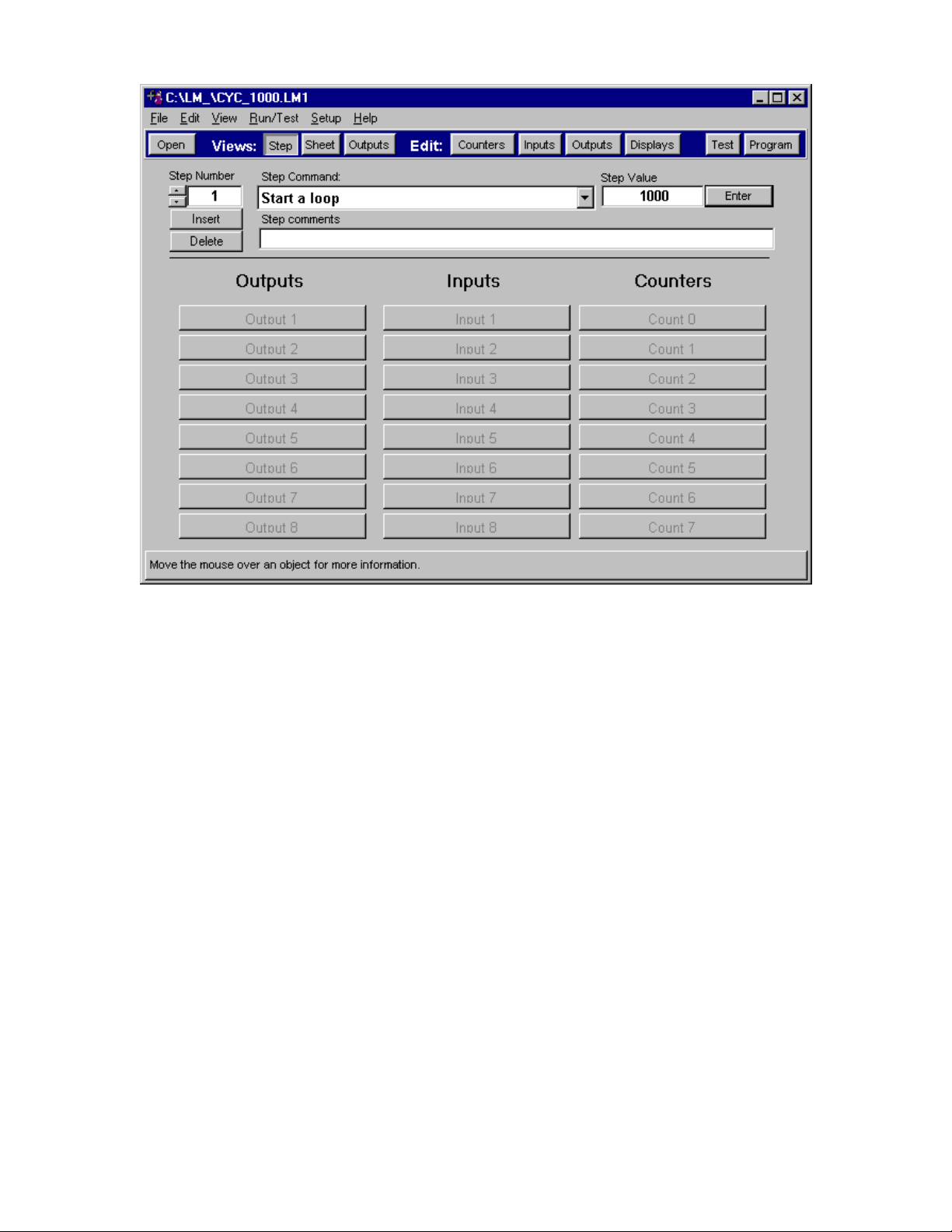
THE STEP VIEW
Step view shows the procedure one step at a time (Figure 13). From this view, the OM -LMPLC procedure
can be completely built. Here you can navigate through the steps, insert steps, delete steps, change the
step action, and add comments.
This view shows all the information about the current step. The current step is indicated by the box under
the "Step Number" label. This view shows the step command, step value, comments and
Input/Output/Counter associati on.
You can navigate the steps by clicking on the up-down arrows under the “step number” caption. Clicking
on the up arrow decreases the step number while clicking the down arrow increases the step number.
You can change the current step command by clicking the down arrow to the right of the current step
command. This will drop down a list of step commands. After selection, “Procedure Writer” will change the
currently displayed value to the selected command's default.
If the step has a value, the “Pro cedure Writer” will allow you to adjust it by clicking on the “Enter” button.
When you click this button, a dialog box will appear allowing you to manipulate that step’s value.
To insert a step before the current step, click on the “Insert” button. Procedure Writer will then ask if it is
okay to delete step 96. Deleting the last step is required because the OM-LMPLC can only execute 96 steps.
To delete the current step, click the “Delete” button. “Procedure Writer” will then verify your delete action.
If you respond with yes, the current step will be deleted.
Note It is important to re-adjust jump steps after insert and delete commands if they are affected.
When a command that requires an output, an input, or a counter the associated buttons will become
enabled. To select the input/output/counter just click the button corresponding to input/output/counter
which you wish to select. A button that is pressed is selected and a button that is not pressed is not
selected.
Add comments to the cur rent step by entering text into box below “Step comments”.
Page 27 of 47
Page 28
OM-LMPLC - User’s Documentation - Omega
Figure 13 - Procedure Writer Step View
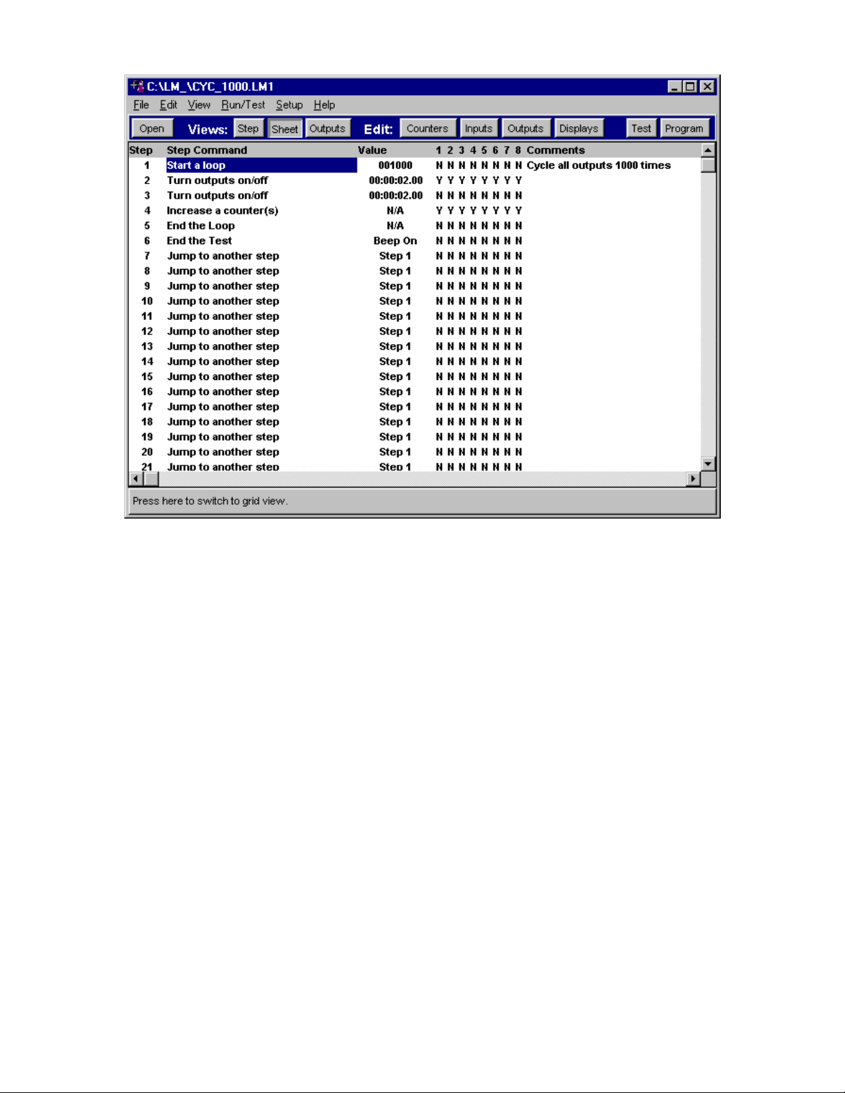
THE SHEET VIEW
The sheet view gives a spreadsheet type view of the procedure (Figure 14). It shows all the steps from 1 to
96. From this view, you can adjust step values and output/input/counter connections. This view is
especially useful for setting up the jump values, since you can immediately see the step you wish to jump to.
To adjust a step’s value, double click on its value. Procedure Writer will then bring up a dialog allowing you
to manipulate this steps value.
To manipulate its outputs/inputs/counters value double click on the column 1-8 to change the value. A “Y”
corresponds to being selected and a “N” corresponds to not being selected.
If you double click on the sheet for anything besides values or output/inputs/counters, Procedure Writer
will switch to step view. The step view’s current step will be the step that was double clicked on in the
sheet view. This provides a quick way to switch to any step in the procedure.
Page 28 of 47
Page 29
OM-LMPLC - User’s Documentation - Omega
Figure 14 - Sheet View
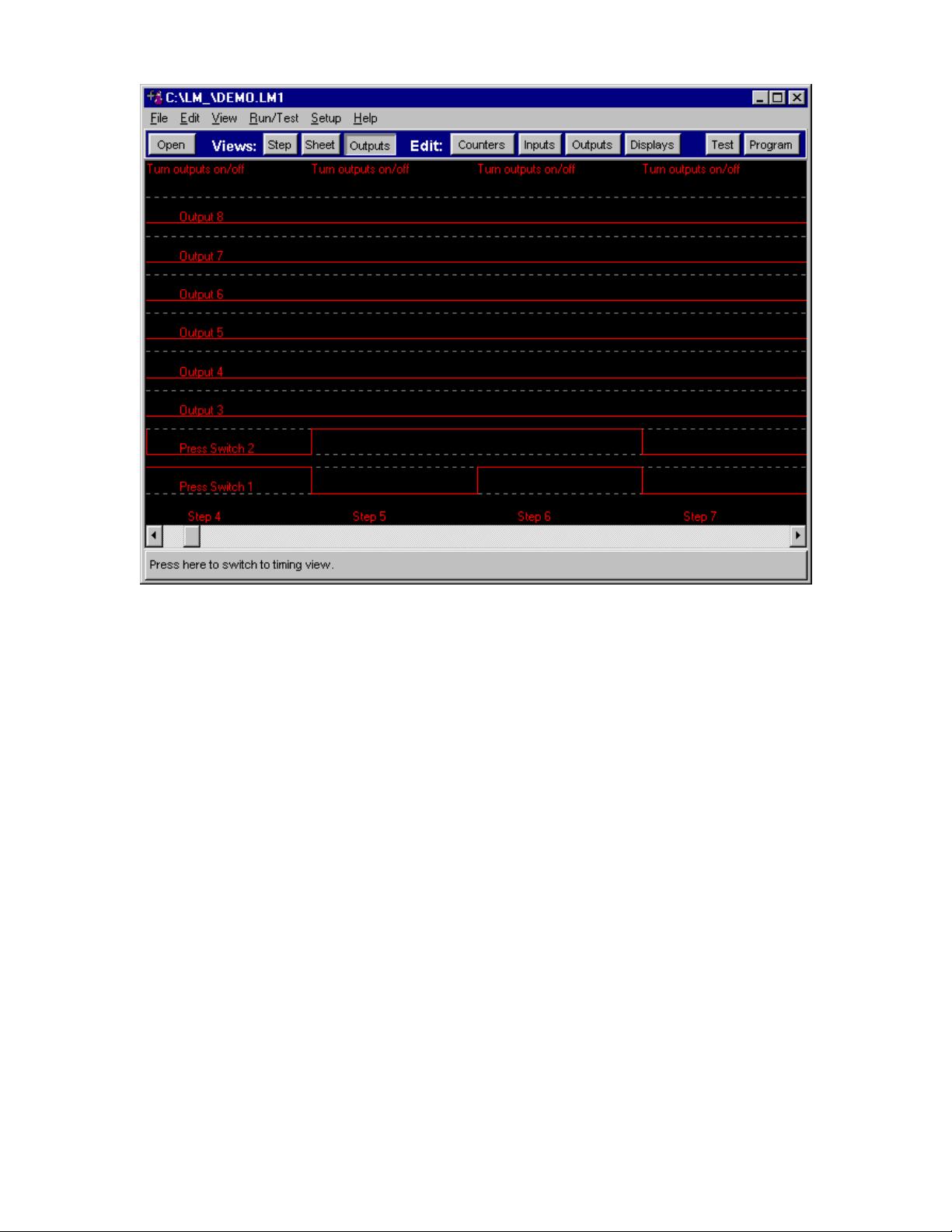
THE OUTPUT VIEW
This view gives graphical view of the outputs by step (Figure 15). This view helps you see relationships
between turning different outputs on and off. Since this representation is by step, this view is not based on
timing.
In complex procedures where a lot of jumping is done, this display may not be meaningful. Only on intervals
where the “Turn Outputs on/off” commands are used will this display accurately reflect the output
relationships.
Page 29 of 47
Page 30
OM-LMPLC - User’s Documentation - Omega
Figure 15 - Output View
EDITING THE CUSTOM DISPLAYS
To enter the custom test information and test complete displays, choose the “Custom Displays…” from the
“Edit” pull down menu. This will show a screen where you can edit the OM -LMPLC’s custom displays
(Figure 16).
The box labeled “Test Banner” is the text that is shown on the top line of most of the OM-LMPLC's screens.
Usually, you will enter a descriptive name for the test you are performing. The test information display’s
line two and three are described here. A simulation of what the test information display would look like is
shown in the yellow box on the right.
The test complete screen is also entered on this screen. Fill in the boxes labeled “Test complete line 2” and
“Test complete line 2” with the information you want shown on the LCD display. This display will be
shown when the OM -LMPLC encounters an “End Test” command. A simulation of what the test complete
display would look like is shown in the yellow box on the right.
Page 30 of 47
Page 31

OM-LMPLC - User’s Documentation - Omega
Figure 16 - Entering Custom Displays
CUSTOM INPUT, OUTPUT, AND COUNTER NAMES
The Procedure Writer allows you to give your outputs, inputs, and counters custom names. This is helpful
while you are building your procedure because you can refer to your outputs, inputs, and counters by name
instead of number. This also is needed for descriptive wire lists and printing. The custom counter names are
displayed on the OM-LMPLC’s LCD display.
You can name them by making the appropriate selection from the edit menu. When you select the in puts,
for example, you will see a screen that allows you to edit the names (Figure 17).
Figure 17 - Naming Inputs, Outputs, and Counters
Page 31 of 47
Page 32

OM-LMPLC - User’s Documentation - Omega
MODIFYING ONBOARD COUNTS
Procedure Writer allows you to preset the OM-LMPLC’s on board counters to any value within their
counting range. This is useful for test samples that may have been pre-cycled and already have cycle
counts. You can also use this feature to reset the counters without resetting the current procedure.
To access this feature, choose “On board counts” from the edit pull down menu. Making this selection
shows the “Edit current counts” dialog (Figure 18 - Edit current counts dialog). Obviously, you need to
have the serial cable attached to read the on-board counts from the OM-LMPLC. To save your changes to
the OM-LMPLC, choose “Ok”. If you wish to keep the current counts, choose “Cancel”.
Figure 18 - Edit current counts dialog
PROCEDURE WRITER OPTIONS
To serve the needs of different users of the OM-LMPLC and Procedure Writer, Procedure Writer has
application options. You can setup the options of the Procedure Writer through the options selection from
the setup pull down. Selecting this pull down will show the options dialog (Figure 19).
Setting up a Comm port
You have to tell the Procedure Writer which Comm port you are using to communicate with the OM-LMPLC.
This is done by selecting “Options” from the “Setup” pull down menu. This selection will show a screen
allowing you to select the Comm port (Figure 19). Select the Comm port from the drop down box and click
ok.
Page 32 of 47
Page 33

OM-LMPLC - User’s Documentation - Omega
Automatically Reset Counts when programmed
The Procedure Writer can automatically reset the OM -LMPLC’s counters when it is programmed. To enable
this feature select the “Automatically reset counters when programmed” in the options dialog. To manually
reset the counters you can use the mode button of the OM-LMPLC or via the “Edit Current Counts” dialog.
Show Adjustment button in the test dialog
You have the option of showing adjustment buttons in the test dialog. These adjustment buttons allow the
user to adjust timing and manipulate the current step shown on the OM -LMPLC. These are provided as an
option because the manipulations are not recorded into the procedure that is on the PC. Therefore, you may
create an inconsistency between the saved procedure on the PC and the procedure in the OM-LMPLC. This
may be unacceptable for organizations that need the documentation features for quality standards.
Figure 19 - Selecting a Comm Port and other Procedure Writer options
TESTING YOUR INPUT AND OUTPUT WIRING
Procedure Writer allows you to test your input and output wiring by manually exercising your outputs. This
is done from the “Test Outputs” screen (Figure 20). You can exercise outputs individually by clicking on
the output buttons. The Inputs are read from the OM-LMPLC a few times a second and are refreshed on the
display.
You also have the option to manipulate the current step’s timing and change the current step of the OM LMPLC. This is done by clicking the buttons in the lower left-hand corner of the test dialog. These buttons
may not appear because they were disabled in the options dialog discussed in the last section.
Page 33 of 47
Page 34

OM-LMPLC - User’s Documentation - Omega
Figure 20 - Testing Input and Output wiring screen
DEBUGGING YOUR PROCEDURE
Follow these steps when you have problems with your procedure. These are the source for the most
common errors in building a OM-LMPLC procedure.
1. Verify output and input wiring using the Test Inputs and Outputs Screen
2. Inspect your procedures Jump type steps and make sure they have correct values
PRINTING YOUR PROCEDURE
The Procedure Writer software allows you to print your procedure. Select “Print…” from the file pull down
menu. A dialog box will be shown allowing you to select the default printer and paper orientation.
DOCUMENTING YOUR PROCEDURE
The Procedure writer can help you document your procedure. From the edit menu, you have three
selections that will transfer procedure information to the Windows clipboard in a tab-separated format.
Then, the information can then be pasted in to your favorite word processor or spreadsheet. For example, in
MS-Word you can paste the procedure, select it, and then convert text to table to turn it into a formatted
table. The selections u nder the edit menu are the following: Copy Current Counts to the clipboard, copy the
procedure to the clipboard, and copy the wire list to the clipboard.
The “Copy current counts to the clipboard” reads the OM-LMPLC’s current counts through the serial cable,
attaches them to the custom names and places them on the Clipboard in a tab-separated format. This feature
Page 34 of 47
Page 35

OM-LMPLC - User’s Documentation - Omega
is very useful if you have counts that exceed the six-digit view on the OM -LMPLC’s PLC display. This
method of reading the counts can read counters up to the internal limit of 16,777,216.
SAVING YOUR PROCEDURE
You can save the current procedure by choosing “Save” from the file pull down menu. If you wish to save
the current procedure to a different name “Choose Save As.”
OPENING YOUR PROCEDURE
You have a few options to opening a previous procedure. The most convenient is to use the Most recent
procedure menu. These are the file names located at the lowest part of the file pull down menu. Other
options are the “Open” selection and the “Open” button on the tool bar.
READING A PROCEDURE FROM THE OM-LMPLC
You can read a procedure from the OM -LMPLC into the PC. To do this, select "Read Program from OMLMPLC" from the Run/Test menu. This will bring up the "Read program from OM-LMPLC" dialog (
Figure 21). From this dialog, you can read the program by clicking the get program button. Note that you
must have the OM-LMPLC connected to get the program.
You have the options to read the counter descriptions and the custom displays. You can also have
procedure Writer erase the existing comments in your procedure.
You can use this feature to update your procedure with the field updates done with the field programmer. To
do this, you can load the original procedure and read the program out of the OM-LMPLC. Since you do not
erase existing comments, your changes will be updated and your comments will remain.
Note: Your custom names for inputs and outputs are not stored in the OM -LMPLC. Therefore, when you
read the program from the OM -LMPLC your custom names for inputs and outputs will not be there. If you
wish to preserve this information you must load the original procedure and then read the program out of the
OM-LMPLC.
Figure 21 - Rea d the procedure out of the PLC to print it out.
Page 35 of 47
Page 36

OM-LMPLC - User’s Documentation - Omega
USING THE PROCEDURE WIZARD
The Procedure Wizard creates a new procedure and then steps you through all of the custom naming
screens. This is useful when you are beginning a procedure or you are new to writing a procedure.
OM-LMPLC Field Programmer
The OM-LMPLC field programmer allows complete programmability of the PLC without a PC. This is
accomplished through simple menus (Figure 23).
Pressing the custom menu key brings up the main menu display (Figure 22). From this display, you can
select what command you want to perform. The following subsections describe what each menu does.
STEP TIME CMD OUT CNT
Figure 22 - The Main Toolbar for the field programmer is accessed through the CST button
STEP
Selecting step will allow you to change the currently displayed step of the OM-LMPLC. You may select a
step from 1 to 96.
TIME
This selection allows you to adjust the time of a time type step.
CMD
Selecting this will let you change the current command for that particular step.
OUT
This command allows you to change the state of each individual output.
CNT
This command lets you adjust the value of any of the counters.
Page 36 of 47
Page 37

OM-LMPLC - User’s Documentation - Omega
Figure 23 - The OM -LMPLC field programmer allows programming without the PC
DOWNLOADING THE OM-LMPLC FIELD PROGRAMMER SOFTWARE INTO THE
CALCULATOR
Overview
If you purchased the field programmer from the Omega the software should be already installed. This
software will remain in the calculator forever as long as the batteries are replaced when required. However, in
the case of battery failure or the case where the calculator resets its memory (very rare) you may need to
download the software yourself.
This tutorial shows step-by-step how to move the software from the PC to your calculator. If you have
difficulty or are uncomfortable with this procedure, you may send your calculator to Omega for
reprogramming. Thi s is available for a small fee to cover shipping and handling. Please contact Omega to
obtain an RMA (return material authorization) number prior to shipment.
Steps
1. Locate the file that contains the field programmer software. This file is called: "LMSTUF.txt". You can
find this file on the disk that came with the calculator.
2. Connect the serial cable that came with the field programmer to the serial port on your PC. Connect the
other end to the HP-48G calculator. The cable is multi -sectioned. The first section is the one that you
normally connect to the PLC. The second section is an adapter from the OM-LMPLC's connector and
the PC's connector.
3. Power on the calculator.
4. Select the I/O menu by hitting the green right arrow on the calculator and then hitting the One key.
5. Select "Transfer" from the menu.
6. From the "Transfer" setup select all of the following options: 1) Port: Wire, 2) Type: Kermit, 3) Name:
blank, 4)fmt: ASCII, 5)XLAT: New1, 6)chk: 3, 7)Baud: 9600, 8) Parity: None 9) ovrw: checked.
Page 37 of 47
Page 38

OM-LMPLC - User’s Documentation - Omega
7. Now, start the Hyper-terminal program that comes with Windows95/NT.
8. Select the option to connect directly to the Comm port the calculator is connected to.
9. Then, select all of the following communications options: 1) Bits per second: 9600, 2) Data bits: 8, 3)
Parity: None, 4) Stop bits: 1, and 5) Flow control: none.
10. From the transfer pull down menu select "send file"
11. In the "send file" dialog press browse to select the file you located in step 1. Set the protocol to
"Kermit". Click the send button and immediately hit the receive button on the HP calculator.
12. The file should be transferring. The progress should show up in the monitor.
13. After completion, change the baud rate of the calculator to 1200.
14. Now you must go to the directory with the OM-LMPLC code. Do this by pressing the var button. In the
graphic display, you should see "LMST". Move to that directory by pressing its button. Now select the
OM-LMPLC custom menu by pressing "CST"
15. You are complete.
Advanced programming techniques
The OM-LMPLC command set, although simpl e, can be used to write very powerful logic. The command set
is logically complete meaning that any logic function can be assembled from its commands.
Say we wish to salt spray when switch 1 is on or if switch 2 is off. This could be represented by the Boolean
expression A or not B. Basically; we use jump steps to perform different logical combinations. Our
proceeding wire list should help you in understanding the following examples.
The first example, Example 10, implements our desired procedure. First, it determines if switch 1 is on. If so, it
jumps to the step which performs the salt spray. Otherwise, the OM -LMPLC proceeds to step 2. In step 2 it
determines if switch 2 is off. If so, it jumps to the step which performs the salt spray. If the switch is not off,
it proceeds to the next step. This procedure effectively achieves our goal of having salt sprayed when
switch 1 is on or if switch 2 is off.
Example 10 - Creating Or logic with multiple jump steps
Wire List
Outputs Inputs Counters
1 Spray Salt Sw1 ON Count 1
2 Sw2 ON Count 2
Procedure
Step no Step Command Value 1 2 3 4 5 6 7 8 Comments
1 Jump if inputs are on Step 4 Y N N N N N N N Is SW1 On? Yes, spray salt
2 Jump if inputs are off Step 4 N Y N N N N N N Is SW2 Off? Yes, spray salt
3 Jump to another step Step 1 N N N N N N N N Keep checking
4 Turn outputs on/off 00:00:05.00 Y N N N N N N N Spray Salt for 5 seconds
5 Jump to another step Step 1 N N N N N N N N
Suppose we only wanted salt spray when both sw1 was on and sw2 was off. This could be represented by
the Boolean expression A and not B. To achieve this, we only run step 2 when sw1 is on. So, if we change
step 1 to a “Jump if inputs Off” and change its step number to skip step 2 if there is a condition of sw1 off
(as shown in Example 11).
Page 38 of 47
Page 39

OM-LMPLC - User’s Documentation - Omega
Now, when step 1 is encountered it will only check if switch 2 is off (step 2) if switch 1 is on. Otherwise it will
skip checking switch 2 and proceed to step 3. If switch 1 happened to be on, the OM -LMPLC would not
jump and would proceed to step 2. Then, if switch 2 was off the OM -LMPLC would perform a salt spray.
This new procedure effectively achieves our goal of having salt sprayed when switch 1 is on and if switch 2
is off.
Example 11 - Implementing AND logic with multiple jump steps
New Procedure
Step no Step Command Value 1 2 3 4 5 6 7 8 Comments
1 Jump if inputs are off Step 3 Y N N N N N N N Is SW1 Off? No, check sw2
2 Jump if inputs are off Step 4 N Y N N N N N N Is SW2 Off? Yes, spray salt
3 Jump to another step Step 1 N N N N N N N N Keep checking
4 Turn outputs on/off 00:00:05.00 Y N N N N N N N Spray Salt for 5 seconds
5 Jump to another step Step 1 N N N N N N N N
To further our discussion, say we wished to have sw1 and sw3 on and sw2 off we could be achieve this by
selecting sw3 in step number 1. This would achieve the Boolean formula (A and C) and (not B).
See Omega’s application notes for other useful programming techniques.
Integrating the OM-LMPLC in a Data Acquisition System
The OM-LMPLC’s communications port is designed so that the OM-LMPLC can be used in a data
acquisition as a dedicated I/O controller. Through the communications port you can change outputs, read
counters, read inputs, pause a test, un-pause a test, load a procedure, and read the device status.
The OM-LMPLC is useful in this capacity because it can perform cycling independent of the PC. This would
free the PC to perform other tasks. Such as collect data, monitor error levels, real-time display, or user
interface. Contact Omega’s for the latest utilities for using the OM-LMPLC in this fashion.
Page 39 of 47
Page 40

OM-LMPLC - User’s Documentation - Omega
Section IV - Principles of Operation
Introduction
Understanding how the OM-LMPLC works internally will help you better determine its strengths and
weaknesses.
Step cycles
The OM -LMPLC performs a sequence of steps. Some require a fixed amount of time or no time. There are
also cases when a procedure logic error occurs where a step would take an infinite amount of time. For
example, step 1: jump to step 1 would take an infinite amount of time. Each step cycle lasts 250 ms.
Output steps last a finite amount of time if not set to zero. Wait type steps last either as long as the time out
or no time if input are activated when the step is encountered. Each output step will last exactly as long as
you tell it to in the procedure writer. The remaining steps do not require any time.
It is important to understand what “No time required” means. This means that the OM-LMPLC will
immediately perform this command when it is encountered and move to the next step without ending a step
cycle. The OM -LMPLC can perform ten “non-time” steps per step cycle without affecting your output
timing. This is best explained in the following examples.
Procedure Example A
Step 1: Turn Outputs On/Off 00:00:00.50
Step 2: Turn Outputs On/Off 00:00:00.50
Step 3: Increase Counter(s)
Step 4: Jump to step 1
The previous code will increment the counter once a second with perfect timing. This is because steps 3
and 4 do not require any time and they are implemented immediately when encountered. So, after the time
for step 2 has exhausted, the OM -LMPLC implements the next two steps immediately and proceeds to step
one. The OM-LMPLC implements these steps very quickly with respect to the 250 ms cycle time. So, steps 3
and 4 actually occur early in the time used by step 1.
Procedure Example B
Step 1: Jump if Inputs ON step 3
Step 2: Jump to step 1
Step 3: do something
The previous code example still works but it simply runs ten iterations of this loop every 250 mS. This is
because of the ten non-time step limit per step cycle.
Page 40 of 47
Page 41

OM-LMPLC - User’s Documentation - Omega
Solid State Relays
Solid state relays were chosen because of their superior lifetime characteristOmega. In durability testing,
solid-state relays are superior because of their non-mechanical nature. Please see our references section for
information on where you can learn more about solid state relays.
Please keep in mind that the relays in the OM -LMPLC can easily drive the coils of electromechanical AC or
DC relays, if these are more appropriate for your application.
Page 41 of 47
Page 42

OM-LMPLC - User’s Documentation - Omega
Section V - Maintenance
Introduction
The OM -LMPLC was designed to be Maintenance free. Internally, the OM-LMPLC has a self-resetting fuse
protecting its internal circuitry. So, besides output failure, there is no need to open the OM-LMPLC’s case.
Output failure
If you experience output failure, the OM-LMPLC’s Solid State relays are easily replaced. Each relay is
individually sockected for easy replacement. See the “Replaceable parts section in the appendices for more
information on the solid-state relays.
To replace a Solid State Relay:
1. Remove power from the OM-LMPLC
2. Remove Input and output connector s
3. Remove the eight retainer screws on the back panel
4. Remove the affected relay from its socket. The relays start from the left side at one and continue to the
right.
5. Insert the new relay.
6. Follow steps 1 through 3 in reverse order to reassemble the OM-LMPL C.
Troubleshooting
Use the follow table to assist you in your trouble shooting.
Table 2 - OM -LMPLC Trouble shooting
Problem Possible Solutions
OM -LMPLC Outputs will not turn on 1. Check the state of the output enable button. It should be
“pressed in” in order for the outputs to function
OM -LMPLC will not communicate with
the Procedure Writer software
OM -LMPLC outputs will turn on but
not off
When I return to program mode, the
outputs that were on remain on.
1. Comm port is not configured properly. Try a different Comm
port. Make sure no other devices, such as modems or mice are
conflicting with the Procedure Writer Comm port setting.
2. Cable is not connected.
1. Make sure your are not using AC SSR relays with a DC load.
1. This is the normal operation of the PLC. To disconnect
outputs, use the output enable button.
Page 42 of 47
Page 43

OM-LMPLC - User’s Documentation - Omega
Section VI - Support
Introduction
Omega’s prides itself in the ability to provide outstanding support of its products. This section tells you
how to contact Omega’s when you have problems with the OM-LMPLC that you cannot solve yourself.
Internet Web Site
You can get programming examples, application notes, and software upgrades from our Web Site.
http://dasieee.com
Page 43 of 47
Page 44

OM-LMPLC - User’s Documentation - Omega
Appendices
Specifications
Typical for 25 C, unless noted.
Power Requirements 9-15 VDC @ 170mA maximum
Operating temperature 0 C - 50 C ( 32 - 122 F )
Relative Humidity 5% to 90% Non-condensing
Time base accuracy +/- 3.0 sec /day
Number of Outputs 8
Number of Inputs 8
Input type Opto-isolated parallel LED
Input voltage range 4v - 36V (DC)
Minimum Input Turn Current Contact Omega’s
Minimum Input Pulse Width 250 mS
Step time resolution 0.25 Seconds
Maximum Number of steps per 250ms Step Time 10
Maximum number of steps 96
Max step time ( change outputs) 41.6 Days
Internal Circuit protection Auto-reset fuse
Counter Maximums 999,999 Visible, 16,777,216 kept internally
Loop count Maximums 999,999
Concurrent Loop Counts 2
Approximate Dimensions (LxWxDepth) 7.2x3.6x6.5 inches
Panel Cutout Dimensions (LxW) 7.25x3.625 inches
Output Connector 10 Positions - 1 common per 4 outputs
Input Connector 9 Positions - 1 Common per 8 inputs
Output Specifications
AC Outputs - Crydom part number AO241 SPST-NO miniature SIP Solid State Relays
Line Voltage Range (VAC) Load Current Range A RMS Surge Current 1-Cycle (A peak)
24-120 0.2-1.0 40
DC Outputs - Crydom part number DO0061A SPST-NO miniature SIP solid state relay with bipolar transistor
output
Line Voltage Range (Vdc) Load Current Range (Adc) Surge Current, 1 sec (A peak)
3-60 0.02-1.0 5.0
Page 44 of 47
Page 45

OM-LMPLC - User’s Documentation - Omega
clockwise looking from the
Serial Cable wiring
The following is the wiring diagram for the serial connector on the OM-LMPLC. For the part number of this
connector, see the replacement parts section in the appendices.
3 Pin female
quick
disconnect
1
To OMLMPLC
Pin 1 is closest to the dot
and then numbered
2
3
connector side
3
5
2
9 Pin D-sub
female
To PC
Figure 24 - Serial cable wiring
RS232 protocol summary
Please contact Omega’s for the latest information on RS232 programming and the OM-LMPLC.
Page 45 of 47
Page 46

OM-LMPLC - User’s Documentation - Omega
WARRANTY/DISCLAIMER
OMEGA ENGINEERING, INC. warrants this unit to be free of defects in materials and workmanship for a period of 13 months from
date of purchase. OMEGA Warranty adds an additional one (1) month grace period to the normal one (1) year product warranty to cover
handling and shipping time. This ensures that OMEGA’s customers receive maximum coverage on each product.
If the unit malfunctions, it must be returned to the factory for evaluation. OMEGA’s Customer Service Department will issue an
Authorized Return (AR) number immediately upon phone or written request. Upon examination by OMEGA, if the unit is found to be
defective, it will be repaired or replaced at no charge. OMEGA’s WARRANTY does not apply to defects resulting from any action of the
purchaser, including but not limited to mishandling, improper interfacing, operation outside of design limits, improper repair, or
unauthorized modification. This WARRANTY is VOID if the unit shows evidence of having been tampered with or shows evidence of having
been damaged as a result of excessive corrosion; or current, heat, moisture or vibration; improper specification; misapplication; misuse
or other operating conditions outside of OMEGA’s control. Components which wear are not warranted, including but not limited to
contact points, fuses, and triacs.
OMEGA is pleased to offer suggestions on the use of its various products. However, OMEGA neither assumes responsibility for any
omissions or errors nor assumes liability for any damages that result from the use of its products in accordance with information
provided by OMEGA, either verbal or written. OMEGA warrants only that the parts manufactured by it will be as specified and free of
defects. OMEGA MAKES NO OTHER WARRANTIES OR REPRESENTATIONS OF ANY KIND WHATSOEVER, EXPRESS OR IMPLIED, EXCEPT
THAT OF TITLE, AND ALL IMPLIED WARRANTIES INCLUDING ANY WARRANTY OF MERCHANTABILITY AND FITNESS FOR A PARTICULAR
PURPOSE ARE HEREBY DISCLAIMED. LIMITATION OF LIABILITY: The remedies of purchaser set forth herein are exclusive, and the total
liability of OMEGA with respect to this order, whether based on contract, warranty, negligence, indemnification, strict liability or otherwise,
shall not exceed the purchase price of the component upon which liability is based. In no event shall OMEGA be liable for consequen tial,
incidental or special damages.
CONDITIONS: Equipment sold by OMEGA is not intended to be used, nor shall it be used: (1) as a “Basic Component” under 10
CFR 21 (NRC), used in or with any nuclear installation or activity; or (2) in medical applications or used on humans. Should any
Product(s) be used in or with any nuclear installation or activity, medical application, used on humans, or misused in any way, OMEGA
assumes no responsibility as set forth in our basic WARRANTY / DISCLAIMER language, and, additionally, purchaser will indemnify
OMEGA and hold OMEGA harmless from any liability or damage whatsoever arising out of the use of the Product(s) in such a manner.
RETURN REQUESTS / INQUIRIES
Direct all warranty and repair requests/inquiries to the OMEGA Customer Service Department. BEFORE RETURNING ANY PRODUCT(S)
TO OMEGA, PURCHASER MUST OBTAIN AN AUTHORIZED RETURN (AR) NUMBER FROM OMEGA’S CUSTOMER SERVICE DEPARTMENT (IN
ORDER TO AVOID PROCESSING DELAYS). The assigned AR number should then be marked on the outside of the return package and on
any correspondence.
The purchaser is responsible for shipping charges, freight, insurance and proper packaging to prevent breakage in transit.
FOR WARRANTY RETURNS,
please have the following information available BEFORE contacting
OMEGA:
1. Purchase Order number under which
the product was PURCHASED,
2. Model and seria l number of the
product under warranty, and
3. Repair instructions and/or specific
problems relative to the product.
FOR NON-WARRANTY REPAIRS, consult OMEGA for current repair charges.
Have the following information available BEFORE contacting OMEGA:
1. Purchase Order number to cover the
COST of the repair,
2. Model and serial number of the product, and
3. Repair instructions and/or specific problems
relative to the product.
Page 46 of 47
Page 47

OM-LMPLC - User’s Documentation - Omega
Procedure Writer - License Agreement
You must agree to the fol lowing agreement before using the Procedure Writer programming software.
If you find an exception with the terms of this agreement, you must return the diskette package unopened
promptly to the dealer from which it was purchased for a refund.
Omega’s Program License Agreement
LICENSE
This software and the user’s documentation are protected by both United States Copyright Law and
International Treaty Provisions. Therefore, you must treat the software just like a book with the following
exception. OMEGA allows you to make backup copies of the software for the sole purpose of backing up
your software and protecting your investment in the software from loss.
By saying, “Just like a book”, OMEGA means, for example, that this software may be used by any number of
people and may be freely moved from one computer to another. Just like a book that it can not be read by
two different people in two different places at the same time. Otherwise, the copyright will be violated.
WARRANTY
OMEGA warrants the diskette(s) on which this software is recorded to be free from physical defects and
faulty workmanship for a period of 1 year from the date of purchase. If a defect in the diskette(s) should
occur during this period, OMEGA will replace the defective diskette(s) without charge.
All other warranties, whether expressed or implied, including the implied warranties of merchantability or
fitness for a particular purpose, are hereby disclaimed.
It is understood that it is the nature of evolving programming and the development of software that
occasional “bugs,” errors, and/or other malfunctions of programs may be generated. It is understood that
OMEGA, its directors, and all the employees of OMEGA shall not be held liable for any claim arising from
the use, interpretation of losses of whatever nature which may arise from OMEGA software or other
materials. If you are not willing to agree to these terms, return this package unopened.
Page 47 of 47
 Loading...