

Page 1
24-Bit Multifunction USB Data Acquisition Modules for
Temperature and Voltage Measurement
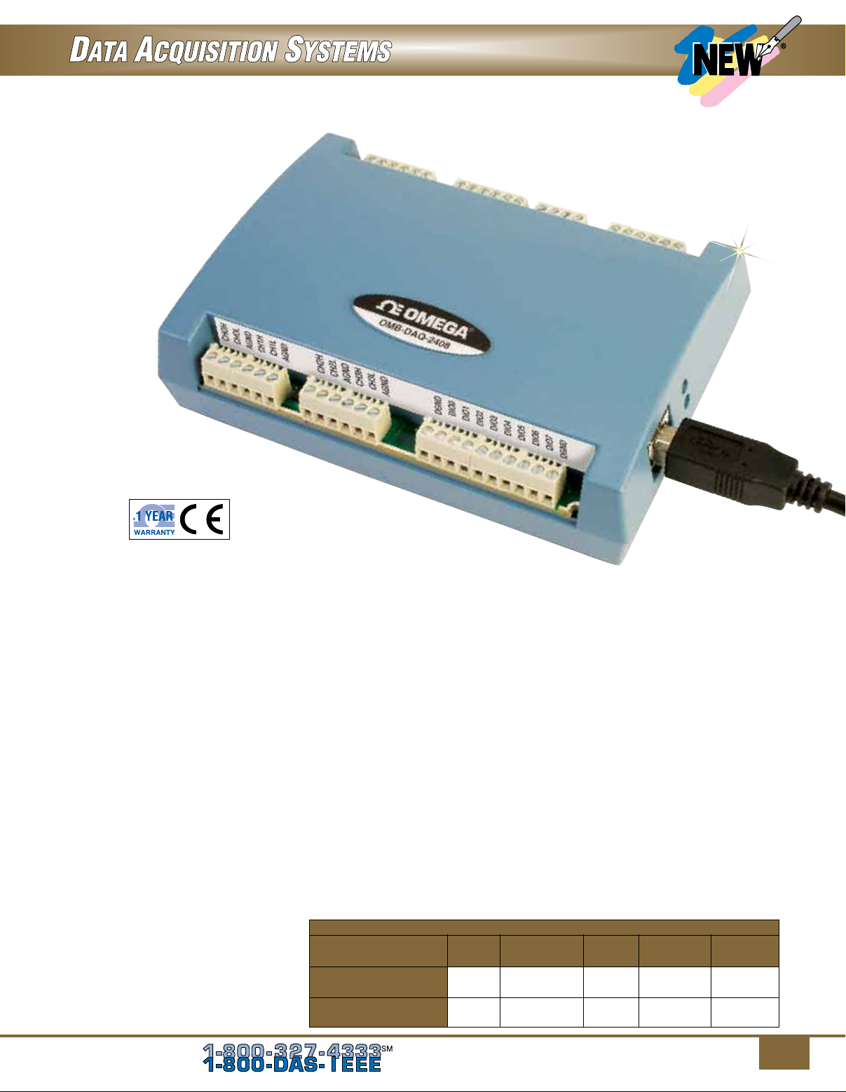
OMB-DAQ-2408 Series
U Measures Thermocouples
or Voltage
U Up to 16 Analog Inputs
U 24-Bit Resolution
U Up to 1 kS/s Sampling
U Two Counters
U Supports Thermocouple Types
J, K, T, E, R, S, B, N
U Built-In Cold Junction
Compensation and Open
Thermocouple Detection
U Eight Digital I/O
U Up to 2 Analog Outputs
U 500 Vdc Isolation Between
Field Wiring and the USB
Interface
The OMB-DAQ-2408 Series are
multifunction DAQ devices designed
for highly-accurate voltage or
temperature measurements. Each
device features up to 16 single
ended (SE)/8 differential (DIFF)
analog inputs. Each device includes
8 digital I/O and two counter inputs.
The OMB-DAQ-2408-2AO also
features two analog outputs. Each
device in the series offers 24-bit
resolution for ultra-accurate voltage
or thermocouple measurements.
OMB-DAQ-2408
shown smaller than
actual size.
Digital I/O
Analog Input
Each device includes 16 SE/8
DIFF analog inputs which you
can configure for voltage or
thermocouple input on a per-channel
basis. Eight software-selectable
voltage input ranges are provided.
You can configure these ranges
on a per-channel basis from ±10V
to ±0.078V. When measuring
thermocouples, configure analog
inputs in DIFF mode. All devices also
include open thermocouple detection
to identify improperly working
thermocouples.
Sample Rate
OMB-DAQ-2408 modules can sample
analog input channels at up to 1 kS/s.
OMB-DAQ-2408 Series Selection Chart
Analog Throughput Analog
Model Inputs Rate Outputs Digital I/O Counters
OMB-DAQ-2408
8 DIFF
OMB-DAQ-2408-2AO
8 DIFF
16 SE/
16 SE/
Up to 1 kS/s — 8 2
Up to 1 kS/s 2 8 2
Eight digital I/O channels are
included with each OMB-DAQ-2408
and you can read from or write to
each individual bit.
Counters
Two 32-bit counters are included
with OMB-DAQ-2408 modules. The
TTL level inputs are capable of read/
write rates of up to 500 Hz and an
input frequency of up to 1 MHz.
Analog Output
(OMB-DAQ-2408-2AO Only)
The OMB-DAQ-2408-2AO includes
two 16-bit analog outputs. Each
output has a ±10V range. Both
outputs can be updated at a rate of
up to 500 S/s per channel; one output
can be updated at a rate of 1 kS/s.
To Order, Call or Shop Online at omega.com
SM
1
Page 2
Software
The OMB-DAQ-2408 modules ship
with an impressive array of software,
including the new TracerDAQ®, a fullfeatured, out-of-the-box data logging,
viewing, and analysis application.
Driver support and detailed
example programs are included
for Universal Library programming
libraries for Microsoft
Studio® programming languages,
and other languages, including
DASYLab®, and ULx for NI
LabVIEW® (comprehensive library
of Vls and example programs
compatible with 32-bit and 64-bit
LabVIEW v8.5 through 2012) and
InstaCalTM installation, calibration
and test utility-powerful solutions for
programmers and nonprogrammers
alike. These modules operate under
Micrsoft Windows® XP (32-bit only)
and VISTA/7/8 (32-bit and 64-bit)
operating systems.
®
Visual
Features Comparison
Strip Chart
Features TracerDAQ TracerDAQ Pro
Channel Types Analog input, temperature input, Analog input, temperature input,
digital input, event counter digital input, event counter
Number of Channels 8 48
Number of Lanes 2 8
Maximum Samples per Channel 32,000 1 million
Alarm Conditions No Yes
Measurements Window No Yes
Enter Annotations No Yes
Software Triggering No Yes
Hardware Triggering No Yes
Time-of-Day Triggering No Yes
Linear Scaling No Yes
Oscilloscope
Features TracerDAQ TracerDAQ Pro
Channel Type Analog input Analog input
Number of Channels 2 4
Measurements Window No Yes
Reference Channel No Yes
Math Channel No Yes
Function Generator
Features TracerDAQ TracerDAQ Pro
Channel Type Analog output Analog output
Number of Channels 1 16
Waveform Types Sine Sine, square, triangle, flat, pulse, ramp, random, arbitrary
Duty Cycle No Yes
Phase No Yes
Gate Ratio No Yes
Rate Multiplier No Yes
Sweep (Linear and Exponential) No Yes
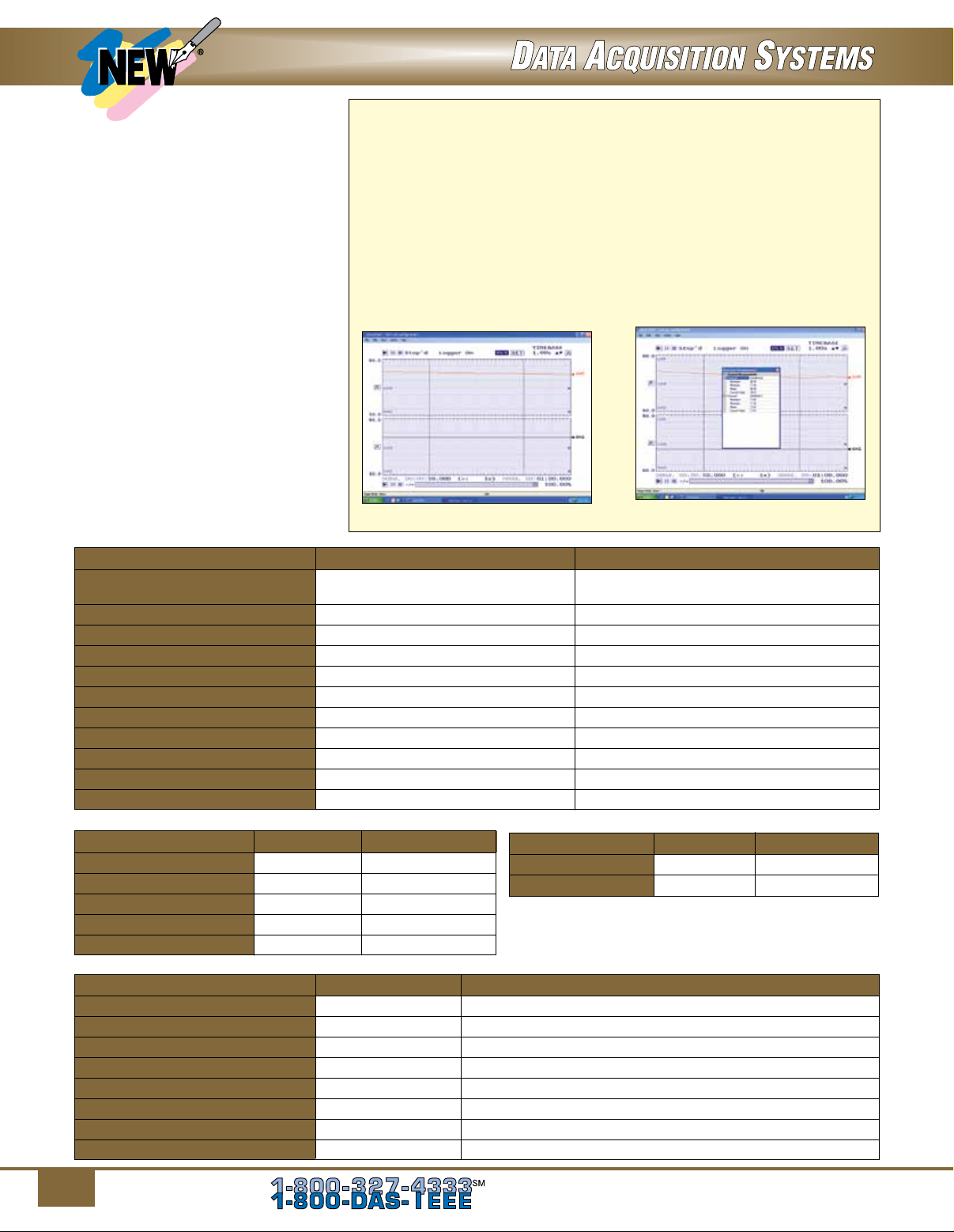
The OM-USB-2408 Series data acquisition modules are supplied with
TracerDAQ software which is a collection of four virtual instrument
applications used to graphically display and store input data and
generate output signals:
• Strip Chart—Log and graph values acquire from analog inputs,
digital inputs, temperature inputs and counter inputs
• Oscilloscope—Display values acquired from analog inputs
• Function Generator—Generate waveforms for analog outputs
• Rate Generator—Generate waveforms for counter outputs
TracerDAQ PRO is an enhanced version of TracerDAQ.
of some of the features included in TracerDAQ vs TracerDAQ PRO is
shown below.
TracerDAQ Strip Chart.
Rate Generator
Features TracerDAQ TracerDAQ Pro
Channel Type Counter output Counter output
Number of Channels 1 20
SWD-TRACERDAQ-PRO Strip Chart with
Measurements (sold separately).
A comparison
2
To Order, Call or Shop Online at omega.com
SM
Page 3

Specifications
ANALOG INPUT
A/D Converter Type: ADS1256,
24-bit Sigma Delta
A/D Data Rates: 3750 S/s, 2000 S/s,
1000 S/s, 500 S/s, 100 S/s, 60 S/s,
50 S/s, 25 S/s, 10 S/s, 5 S/s, 2.5 S/s
Throughput (Software-Selectable
for Single Channel and Multiple
Channels)
Single Channel:
2.5 to 1102.94 S/s
Multiple Channels:
0.16 to 1102.94 Hz
Number of Channels: Up to 16
channels individually softwareselectable as single ended (SE) or
differential (DIFF); thermocouples
require differential mode; for each
channel configured as differential,
you lose one single-ended channel
Input Isolation: 500 Vdc minimum
between field wiring and USB
interface
Channel Configurations:
Temperature sensor input, softwareselectable to match sensor type;
voltage input
Input Voltage Range
Thermocouple Mode:
±0.078125V
Voltage Mode
(Software-Selectable):
±10V, ±5V, ±2.5V, ±1.25V,
±0.625V, ±0.3125V, ±0.15625V,
±0.078125V
Absolute Maximum Input Voltage
CxH-CxL Relative to GND:
±22V max (power on),
±10V maximum (power off)
Input Impedance: 10 MΩ
(power on), 390 Ω (power off)
Input Leakage Current: ±20 nA
Input Voltage: >±22V (power on/
off): ±1µ A maximum
Input Capacitance: 590 pf
Maximum Working Voltage
(Signal + Common Mode)
Voltage Mode: ±10.25V maximum
Common Mode Rejection Ratio
Thermocouple Mode
= 60 Hz): 110 dB
(f
IN
Voltage Mode (f
All Input Ranges): 90 dB
ADC Resolution: 24 bits
Crosstalk: Adjacent channels, 100 dB
= 60 Hz,
IN
Input Coupling: DC
Channel Gain Queue: Up to 64
elements, software-selectable
channel and range
Warm-Up Time: 45 minutes min
Open Thermocouple Detect:
Software-selectable for each
channel
CJC Sensor Accuracy
15 to 35°C: ±0.5°C typ
0 to 55°C: ±1.0°C maximum
THROUGHPUT RATE
The maximum throughput of an
OMB-DAQ-2408 module is 1.1 kS/s
aggregate. The OMB-DAQ-2408
provides the ability to set conversion
rates on a per-channel basis.
This feature gives the user flexibility
and control over noise averaging for
each channel.
ANALOG VOLTAGE OUTPUT
(OMB-DAQ-2408-2AO ONLY)
Digital to Analog Converter:
DAC8552
Number of Channels: 2
Resolution: 16-bits
Output Ranges
Calibrated: ±10 V
Uncalibrated: ±10.05V,
software-selectable
Output Transient
Host computer is reset, powered
on, suspended or a reset command
is issued to device
Duration: 2 s
Amplitude: 2V p-p
OMB-DAQ-2408
shown smaller than
actual size.
Initial Power On
Duration: 50 ms
Amplitude: 5V peak
Differential Non Linearity:
±0.25 LSB typ, ±1 LSB maximum
Output Current: AOUTx pins,
±5.0 mA maximum
Power On and Reset State:
DACs cleared to zero-scale, 0V,
±50 mV
Settling Time: To rated accuracy,
10V step, 75 μs
Slew Rate: 1.0 V/μs
Throughput
Single-Channel: 1000 S/s
maximum, system-dependent
Multi-Channel: 1000 S/s /#ch
maximum, system-dependent
Calibrated Absolute Accuracy
Range: ±10V
Accuracy (±LSB): 16.0
DIGITAL INPUT
Number of I/O: 8 channels
Configuration: Each DIO bit can
be independently read from (DIN)
or written to (DOUT). DIN bits can
be read at any time whether the
DOUT is active or tri-stated.
Input Voltage Range: 0 to 15V
Input Type: CMOS (Schmitt
trigger)
Input Characteristics:
47 kΩ pull-up/pull-down resistor,
28 kΩ series resistor
Maximum Input Voltage Range:
0 to 20V maximum (power on/off,
relative to DGND)
To Order, Call or Shop Online at omega.com
SM
3
Page 4

Thermocouple Accuracy Specifications*
Includes CJC Measurement Error and Polynomial Linearization Error
Specifications Valid for 1-Year or 3000 Operating Hours, Whatever Comes First
Thermocouple Sensor Temp Accuracy Error, Accuracy Error, Tempco
Range Maximum °C Typical °C (°C/°C)
-210°C ±2.572 ±1.416
0°C ±0.935 ±0.469 ±0.022
1200°C ±1.869 ±1.45
-210°C ±2.917 ±1.699
0°C ±1.017 ±0.526 ±0.029
1372°C ±2.478 ±2.022
-200°C ±3.480 ±2.030
0°C ±1.201 ±0.659 ±0.029
1300°C ±1.991 ±1.600
-50°C ±4.826 ±3.133
250°C ±2.117 ±1.424 ±0.082
1768°C ±2.842 ±2.347
-50°C ±4.510 ±2.930
250°C ±2.165 ±1.468 ±0.089
1768°C ±3.187 ±2.597
250°C ±5.489 ±3.956
700°C ±2.283 ±1.743 ±0.14
1820°C ±2.202 ±1.842
-200°C ±2.413 ±1.352
0°C ±1.069 ±0.551 ±0.017
1000°C ±1.575 ±1.211
-200°C ±2.821 ±1.676
0°C ±1.050 ±0.558 ±0.027
400°C ±0.957 ±0.595
*Each terminal block has a CJC sensor. The accuracy listed above assumes the screw terminals are at the same temperature as the CJC sensor.
Pull-Up/Pull-Down Configuration:
All pins pulled up to 5V through
individual 47 kΩ resistors (the J6
shorting block default position is
pins 1 and 2) Pull-down capability is
available by placing the J6 shorting
block across pins 2 and 3
Transfer Rate (Software Paced):
500 port reads or single bit reads
per second typ
Input High Voltage: 1.3 to 2.2V
Input Low Voltage: 1.5 to 0.6V
Schmitt Trigger Hysteresis:
0.4V to 1.2
DIGITAL OUTPUT
Number of I/O: 8 channels
Configuration: Each DIO bit can
be independently read from (DIN) or
written to (DOUT). DIN bits can be
read at any time whether the DOUT
is active or tri-stated.
Output Characteristics: 47 kΩ
pull-up, open drain (DMOS transistor)
Each DMOS transistor source pin is
internally connected to DGND
Pull-Up Configuration: All pins
pulled up to 5V through individual
47 kΩ resistors (the J6 shorting
block default position is pins 1 and 2).
Transfer Rate (Software Paced)
Digital Output: 500 port writes or
single bit writes per second typ
Output Voltage Range: 0 to 5V
(no external pull up resistor, internal
47 kΩ pull-up resistors connected to
5V by default); 0 to 15V maximum
Drain to Source Breakdown
Voltage: 50V minimum
Off State Leakage Current: 1.0 µA
Sink Current Capability: 150 mA
max (continuous) per output pin
150 mA maximum (continuous) for all
eight channels
DMOS Transistor On-Resistance
(Drain to Source): 4 Ω
COUNTER
Pin Names: CTR0, CTR1
Number of Channels: 2 channels
Resolution: 32-bits
Counter Type: Event counter
Input Type: Schmitt trigger, rising
edge triggered
Input Source: CTR0 (pin 44),
CTR1 (pin 42)
Counter Read/Writes Rates
(Software Paced)
Counter Read: System
dependent, 500 reads per second
Counter Write: System dependent,
500 writes per second
Input Characteristics: Each CTRx
input pin has 562 kΩ resistor pulled
up to 5V and a 10 kΩ series resistor
Input Voltage Range: ±15V
maximum
Maximum Input Voltage Range:
CTR0, CTR1 relative to GND and
DGND, ±20V maximum (power on/
off)
Input High Voltage: 1.3 to 2.2V
Input Low Voltage: 1.5 to 0.6V
Schmitt Trigger Hysteresis:
0.4 to 1.2V
Input Bandwidth (-3 dB): 1 MHz
Input Capacitance: 25 pf
Input Leakage Current: ±120 nA
@5V, ±1.6 mA @±15V
Input Frequency: 1 MHz, maximum
High Pulse Width: 500 ns, minimum
Low Pulse Width: 500 ns, minimum
4
To Order, Call or Shop Online at omega.com
SM
Page 5

Analog Input DC Voltage Measurement Accuracy
Gain Offset
Temperature Temperature
Gain Error Offset Error INL Error Coefficient Coefficient
Range (% of reading) (% of range) Accuracy Absolute (% reading/°C) (µV/°C)
±10V ±0.0037 50 µV ±0.0008 500 µV ±0.0006 3
±5V ±0.0047 25 µV ±0.0008 300 µV ±0.0006 2
±2.5V ±0.0059 20 µV ±0.0008 200 µV ±0.0006 1
±1.25V ±0.0056 20 µV ±0.0008 100 µV ±0.0006 1
±0.625V ±0.0068 15 µV ±0.0005 60 µV ±0.0006 1
±0.3125V ±0.0104 15 µV ±0.0006 50 µV ±0.0006 1
±0.15625V ±0.0184 10 µV ±0.0005 40 µV ±0.0006 1
±0.078125V ±0.0384 10 µV ±0.0009 40 µV ±0.0006 1
MEMORY
EEPROM: 4096 bytes isolated
micro reserved for sensor
configuration, 256 bytes USB micro
for external application use
MICROCONTROLLER
Type: One high-performance
8-bit RISC microcontroller with
USB interface (non-isolated); one
high-performance 16-bit RISC
microcontroller for measurements
(isolated)
POWER
Supply Current: Quiescent current,
275 mA (includes up to 10 mA for
the status LED; does not include
any potential loading of the digital
I/O bits, 5V user terminal or the
AOUTx outputs).
5V User Output Voltage Range:
Available at terminal block pin 40,
4.75 to 5.25V
5V User Output Current: Available
at terminal block pin 40, 10 mA
maximum
Isolation: Measurement system
to PC, 500 Vdc minimum
USB SPECIFICATIONS
USB Device Type: USB 2.0
(full-speed)
Device Compatibility: USB 1.1,
USB 2.0
USB Cable Length:
3 m (9.8') maximum
ENVIRONMENTAL
Operating Temperature Range:
0 to 50°C (32 to 12°F)
Storage Temperature Range:
-40 to 85°C (40 to 185°F)
Humidity: 0 to 90% RH
non-condensing
MECHANICAL
Dimensions: 127 L × 89.9 W × 35.6
mm D (5.00 × 3.53 × 1.40")
Weight 160 g (5.6 oz)
SCREW TERMINAL CONNECTOR
Connector Type: Fixed screw terminal
Wire Gauge Range: 16 to 30 AWG
SM
Extended Warranty
Program
SM
OMEGACARE
available for models shown on this page. Ask
your sales representative for full details when
placing an order. OMEGACARE
labor and equivalent loaners.
extended warranty program is
SM
covers parts,
To Order Visit omega.com/omb-daq-2408 for Pricing and Details
Model No. Description
OMB-DAQ-2408 24-bit, isolated, 16 SE/8 DIFF temperature and voltage USB data acquisition module,
OMB-DAQ-2408-2AO 24-bit, isolated, 16 SE/8 DIFF temperature and voltage USB data acquisition module,
SWD-TRACERDAQ-PRO TracerDAQ Pro software
Comes complete with a 2 m (6') USB cable, Quick Start Guide, TracerDAQ software and operator’s manual on CD.
Ordering Example: OMB-DAQ-2408-2AO 24-bit temperature and voltage USB data acquisition module, 2 analog outputs
and OCW-1 OMEGACARESM 1-year extended warranty adds 1 year to standard 1 year warranty.
To Order, Call or Shop Online at omega.com
8 digital I/O; 2 counters
8 digital I/O; 2 counters, 2 analog outputs
SM
5
 Loading...