

Page 1
http://www.omega.com
e-mail: info@omega.com
omega.com
®
®
User’s Guide
OM2-160
Signal Conditioner System
Page 2

Servicing
North America:
USA:
ISO 9001 Certified
One Omega Drive, Box 4047
Stamford, CT 06907-0047
Tel: (203) 359-1660
FAX: (203) 359-7700
e-mail: info@omega.com
Canada:
976 Bergar
Laval (Quebec) H7L 5A1
Tel: (514) 856-6928
FAX: (514) 856-6886
e-mail: info@omega.ca
For immediate technical or
application assistance:
USA and Canada:
Sales Service: 1-800-826-6342 /
1-800-TC-OMEGA
SM
Customer Service: 1-800-622-2378 /
1-800-622-BEST
SM
Engineering Service: 1-800-872-9436 /
1-800-USA-WHEN
SM
TELEX: 996404
EASYLINK: 62968934 CABLE: OMEGA
Mexico and Latin America:
Tel: (001) 800-826-6342
FAX: (001) 203-359-7807
En Espan~ol: (001) 203-359-7803
e-mail: espanol@omega.com
omega.com
OMEGAnet®On-Line Service Internet e-mail
http://www.omega.com info@omega.com
OMEGA
®
®
Page 3

WARRANTY/DISCLAIMER
OMEGA ENGINEERING, INC. warrants this unit to be free of defects in materials and
workmanship for a period of
13 months from date of purchase. OMEGA Warranty adds an
additional one (1) month grace period to the normal
one (1) year product warranty to cover
handling and shipping time. This ensures that OMEGA’s customers receive maximum coverage
on each product.
If the unit malfunctions, it must be returned to the factory for evaluation. OMEGA’s Customer
Service Department will issue an Authorized Return (AR) number immediately upon phone or
written request. Upon examination by OMEGA, if the unit is found to be defective, it will be
repaired or replaced at no charge. OMEGA’s WARRANTY does not apply to defects resulting
from any action of the purchaser, including but not limited to mishandling, improper interfacing,
operation outside of design limits, improper repair, or unauthorized modification. This WARRANTY is
VOID if the unit shows evidence of having been tampered with or shows evidence of having been
damaged as a result of excessive corrosion; or current, heat, moisture or vibration; improper
specification; misapplication; misuse or other operating conditions outside of OMEGA’s control.
Components which wear are not warranted, including but not limited to contact points, fuses,
and triacs.
OMEGA is pleased to offer suggestions on the use of its various products. However,
OMEGA neither assumes responsibility for any omissions or errors nor assumes
liability for any damages that result from the use of its products in accordance with
information provided by OMEGA, either verbal or written. OMEGA warrants only that
the parts manufactured by it will be as specified and free of defects. OMEGA MAKES
NO OTHER WARRANTIES OR REPRESENTATIONS OF ANY KIND WHATSOEVER,
EXPRESS OR IMPLIED, EXCEPT THAT OF TITLE, AND ALL IMPLIED WARRANTIES
INCLUDING ANY WARRANTY OF MERCHANTABILITY AND FITNESS FOR A
PARTICULAR PURPOSE ARE HEREBY DISCLAIMED. LIMITATION OF LIABILITY: The
remedies of purchaser set forth herein are exclusive, and the total liability of OMEGA
with respect to this order, whether based on contract, warranty, negligence,
indemnification, strict liability or otherwise, shall not exceed the purchase price of
the component upon which liability is based. In no event shall OMEGA be liable for
consequential, incidental or special damages.
CONDITIONS: Equipment sold by OMEGA is not intended to be used, nor shall it be used: (1) as
a “Basic Component” under 10 CFR 21 (NRC), used in or with any nuclear installation or activity;
or (2) in medical applications or used on humans. Should any Product(s) be used in or with any
nuclear installation or activity, medical application, used on humans, or misused in any way,
OMEGA assumes no responsibility as set forth in our basic WARRANTY/ DISCLAIMER language,
and, additionally, purchaser will indemnify OMEGA and hold OMEGA harmless from any
liability or damage whatsoever arising out of the use of the Product(s) in such a manner.
USA
MADE
IN
Page 4

8 Specifications
NOTES
8-8
Page 5

It is the policy of OMEGA to comply with all worldwide safety and EMC/EMI regulations that apply. OMEGA is constantly pursuing
certification of its products to the European New Approach Directives. OMEGA will add the CE mark to every appropriate device
upon certification.
The information contained in this document is believed to be correct, but OMEGA Engineering, Inc. accepts no liability for any
errors it contains, and reserves the right to alter specifications without notice.
WARNING: These products are not designed for use in, and should not be used for, patient-connected applications.
Benelux:
Postbus 8034, 1180 LA Amstelveen
The Netherlands
Tel: (31) 20 6418405 FAX: (31) 20 6434643
Toll Free in Benelux: 0800 0993344
e-mail: nl@omega.com
Czech Republic:
ul. Rude armady 1868, 733 01 Karvina-Hranice
Tel: 420 (69) 6311899 FAX: 420 (69) 6311114
Toll Free: 0800-1-66342
e-mail: czech@omega.com
France:
9, rue Denis Papin, 78190 Trappes
Tel: (33) 130-621-400 FAX: (33) 130-699-120
Toll Free in France: 0800-4-06342
e-mail: france@omega.com
Germany/Austria:
Daimlerstrasse 26, D-75392
Deckenpfronn, Germany
Tel: 49 (07056) 3017 FAX: 49 (07056) 8540
Toll Free in Germany: 0130 11 21 66
e-mail: info@omega.de
United Kingdom: ISO 9002 Certified
One Omega Drive
River Bend Technology Centre
Northbank, Irlam, Manchester
M44 5EX, United Kingdom
Tel: +44 (0) 161 777-6611 FAX: +44 (0) 161 777-6622
Toll Free in United Kingdom: 0800-488-488
e-mail: info@omega.co.uk
RETURN REQUESTS / INQUIRIES
Direct all warranty and repair requests/inquiries to the OMEGA Customer Service Department. BEFORE
RETURNING ANY PRODUCT(S) TO OMEGA, PURCHASER MUST OBTAIN AN AUTHORIZED RETURN (AR)
NUMBER FROM OMEGA’S CUSTOMER SERVICE DEPARTMENT (IN ORDER TO AVOID PROCESSING
DELAYS). The assigned AR number should then be marked on the outside of the return package and on any
correspondence.
The purchaser is responsible for shipping charges, freight, insurance and proper packaging to prevent
breakage in transit.
FOR
WARRANTY RETURNS, please have the
following information available BEFORE
contacting OMEGA:
1. Purchase Order number under which the
product was PURCHASED,
2. Model and serial number of the product under
warranty, and
3. Repair instructions and/or specific problems
relative to the product.
FOR NON-WARRANTY REPAIRS,
consult OMEGA
for current repair charges. Have the following
information available BEFORE contacting OMEGA:
1. Purchase Order number to cover the COST
of the repair,
2. Model and serial number of the product, and
3. Repair instructions and/or specific problems
relative to the product.
OMEGA’s policy is to make running changes, not model changes, whenever an improvement is possible. This affords our
customers the latest in technology and engineering.
OMEGA is a registered trademark of OMEGA ENGINEERING, INC.
© Copyright 1998 OMEGA ENGINEERING, INC. All rights reserved. This document may not be copied, photocopied, reproduced,
translated, or reduced to any electronic medium or machine-readable form, in whole or in part, without the prior written consent
of OMEGA ENGINEERING, INC.
Servicing Europe:
Page 6
NOTE
The carrier will not honor damage claims unless all shipping material
is saved for inspection. After examining and removing contents,
save packing material and carton in event reshipment is necessary.
OM2-160
Signal Conditioner System
Unpacking Information
Remove the Packing List and verify that you have received all
equipment, including the following (quantities in parentheses):
OM2-160 System (1)
Operator’s Manual (1)
If you have any questions about the shipment, please call the
OMEGA Customer Service Department.
When you receive the shipment, inspect the container and
equipment for signs of damage. Note any evidence of rough
handling in transit. Immediately report any damage to the
shipping agent.
TABLE OF
CONTENTS
i
Page 7

Specifications 8
8-7
Stability is defined after a 5 minute warm-up period and with
constant line, load and ambient temperature unless otherwise
specified.
Quiescent current for amplifiers only, the current drawn from the
bridge supply must be added to the +15 Vdc current drain for total
current draw.
Referred to pin J, this is a high impedance output and should not
be loaded greater than 50 micro-amps. Buffer this reference with
an op-amp for greatest accuracy.
(13)
(14)
(15)
Page 8

8 Specifications
8-6
Specifications referred to the filter output (Pin N).
Using on board coarse and fine gain adjust trimpots.
Warm-up drift is specified as the input offset drift for the first 5
minutes after the application of power with G = 1000 V/V, Bridge
supply = 10V driving a 350 ohm bridge.
Measured at 25°C Ambient with unit fully warmed up.
Measured from -Input to +Input with respect to ground.
Specified with 1 kohm source impedance imbalance, 100<Gain <
1000 V/V.
Filter frequency set with DIP switches.
Small signal response, switch or resistor/capacitor selectable, see
Section 1.4.
This is the instrumentation amplifier basic gain bandwidth
product, the filtered output will provide for a constant cutoff
frequency regardless of gain.
The low pass filter cutoff frequency is adjustable to 10, 100 and
1000 Hz using the on board DIP switches and from 1 Hz to 10 kHz
using external resistors and capacitors.
Bridge supply must be operated with +Sense connected to the
Bridge Supply Pin and with -Sense connected to Common.
The bridge supply maximum output current is a function of input
to output voltage differential and temperature. See the graphs in
earlier chapters and Chapter 1 for more information.
(1)
(2)
(3)
(4)
(5)
(6)
(7)
(8)
(9)
(10)
(11)
(12)
NOTES
Page 9

OM2-165
Strain Gage Bridge Signal Conditioner
Page
Chapter 1 Introduction
1.1 Description . . . . . . . . . . . . . . . . . . . . . . . . . . . . . . . . . . . . . . . . . . .1-1
1.2 Function Description . . . . . . . . . . . . . . . . . . . . . . . . . . . . . . . . . . .1-2
1.3 Feature . . . . . . . . . . . . . . . . . . . . . . . . . . . . . . . . . . . . . . . . . . . . . . .1-2
1.4 Application Example . . . . . . . . . . . . . . . . . . . . . . . . . . . . . . . . . .1-3
1.4.1 Digital Scales with Remote Tare Adjustment . . . . . . . . . . . . .1-3
Chapter 2 Instrument Amplifier
Chapter 3 Active Filter
Chapter 4 Filter Cutoff Frequency Adjustment
Chapter 5 Bridge Supply
Chapter 6 Half Bridge Completion/Bridge Balance
Chapter 7 General Calibration Procedures
Chapter 8 Specifications
ii
TABLE OF
CONTENTS
1-1
2-1
3-1
4-1
5-1
6-1
7-1
8-1
Page 10

This page is intentionally blank
OM2-160
Signal Conditioner System
TABLE OF
CONTENTS
iii
Page 11
8-5
Specifications 8
Page 12

8 Specifications
8-4
Min. Typical Max. Units
Output Noise, 10 Hz - 1 k Hz 200 µV p-p
Internal Reference Voltage (15) 6.46 6.80 7.14 Vdc
Half Bridge Completion
Nominal Resistance Value 20 k ohms
Initial Accuracy 1 %
Temperature Tracking 5 ppm/°C
Balance Adjustment Range 5 %
Power Requirements
Voltage Rated Performance ±15 Vdc
Operating ±12 ±18 Vdc
Current (14) ±12 mA
Environmental
Ambient Operating -25 70 °C
Storage -40 100 °C
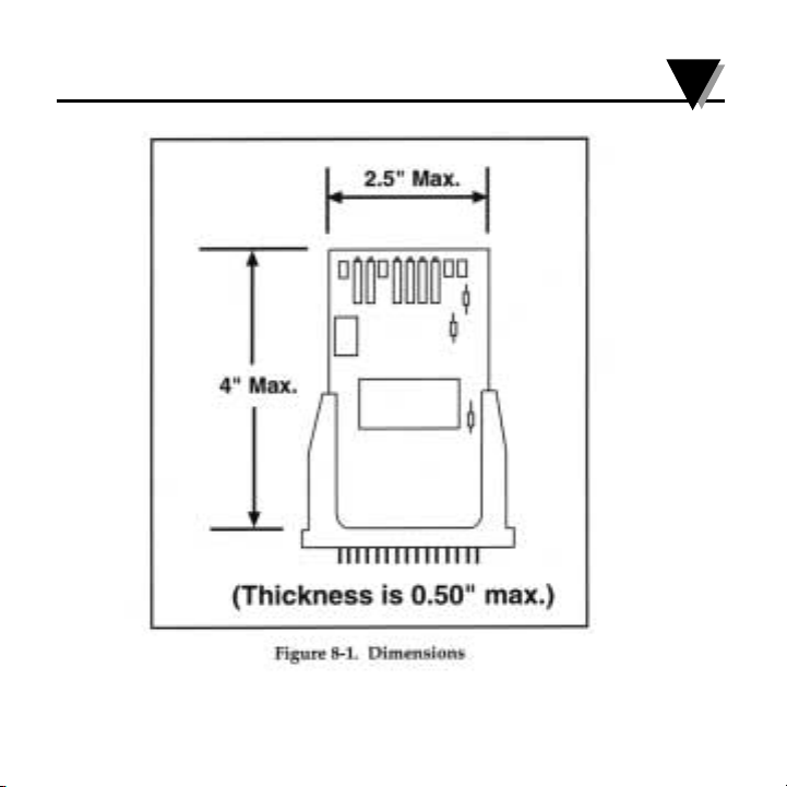
Dimensions See Figure 8-1
Weight 1.5 oz (42.5 g)
Page 13

The OMEGA® OM2-160 BRIDGESENSOR is a complete signal
conditioning system on a card designed expressly for either half or
full bridge transducers. The OM2-160 consists of a high
performance instrumentation amplifier, a user adjustable active
filter, high stability bridge supply and reference regulator in a
state-of-the-art hybrid circuit, which is mounted on a PC board
mounting kit containing all of the required external circuitry,
trimpots, etc., so that only point to point wiring need be made to
the inputs, outputs and power to have a complete signal
conditioning system up and running.
The mounting kit provides coarse and fine gain adjustment
trimpots along with input and output offset adjustments, DIP
switches for setting the bridge supply output and active low pass
filter cutoff frequency.
Application of the OM2-160 is easy by following the detailed
applications information in Section 1.4.
1
Introduction
1-1
1.1 Description
Page 14

1 Introduction
1-2
1.2 Functional Description
1.3 Features
• 1/4, 1/2 and Full Bridge Inputs
• Integral Zero and Span Adjustments
• Gain of 2 to 5000
• Adjustable Filtering
• Remote Sensing Eliminates Lead Resistance Effects
• 0.002% Linearity
The OM2-160 is a completely self contained single channel signal
conditioning system on a card. This device offers the high
performance and reliability of hybrid circuitry with the
completeness of a mounting kit containing all trimpots and
components needed for operation, all that needs to be added is
power and transducer inputs to get a conditioned output suitable
for driving A/D converters, panel meters, indicators, or PC base
controllers.
Page 15

8-3
Specifications 8
Min. Typical Max. Units
Dynamic Response (8)
Small Signal Bandwidth Adjustable kHz
Amp Out Gain Bandwidth (9) 25 MHz
Low Pass Filter (10) Number of Poles 2
dc Gain (Pin P to N) -2 V/V
Roll Off 40 dB/Dec
Bridge Excitation Supply (11)
Output Adjustment Range with Trimpot 4 10 Vdc
with Ext. Resistor 4 12 Vdc
Output Current (12) 0 100 mA
Load Regulation (I
L = 0 - 100mA) 0.1 0.2 %
Line Regulation (V
in
= 14.5 - 18 Vdc) 0.05 0.5 %/V
Stability (13) Short Term 0.05
%/24 hours
Long Term 0.2 %/kHrs
vs. Temperature 40 80 ppm/°C
Warm-up Drift 0.1 %
Short Circuit Protection 8 hours minimum
Page 16

8 Specifications
8-2
Min. Typical Max. Units
Output Offset Adjusted Range ±10 V
Input Bias Current (4) 10 50 nA
vs. Temperature 25 pA/°C
Input Offset Current 5 20 nA
vs Temperature 10 pA/°C
Input Impedance (5) 4G ohms resistor in parallel with 15 pf capacitor
Common Mode Range, Linear Response ±9.5 Vdc
Input Voltage: Maximum ±15 Vdc
CMR (6) 1kHz bw, dc-60 Hz (7) 110 140 dB
10 Hz bw, dc-60 Hz (7) 110 140 dB
Input Noise Voltage 0.1 Hz - 10 Hz 0.3 µV p-p
10 Hz -100 Hz 1 µV p-p
Current 0.1 Hz - 10 Hz 60 pA p-p
10 Hz - 100 Hz 100 pA p-p
Rated Output Voltage, 2k ohm load ±10 Vdc
Current ±5 mA
Load Capacitance 1000 pF
Short Circuit Indefinite
Page 17

Introduction 1
1-3
1.4 Application Example
1.4.1 Digital Scales With Remote Tare Adjustment
The OM2-160 can be used as the heart of a very effective digital
scale system as shown below. The OM2-160 is interfaced to a
standard 3 mV/V full bridge transducer. With the bridge excitation
set to 10 Volts a gain of 333 V/V is required to get a 10 Volt full scale
output. The output offset pin (K) is used here to interface to a front
panel pot by the display, this pot allows a tare or dead weight
adjustment to be made by the operator as a required to set the
system offset to zero reading for zero weight on the scale (resistor
R4 should be removed from the OM2-160 to disable any interaction
of the internal output offset adjustment). The system is calibrated by
applying zero weight with the output offset pin and inputs
connected to ground and adjusting the input offsets to get a zero
reading, then remove the inputs from ground and apply a full scale
load to the scale (or simulate one with a mV calibrator) and
procedure may have to be repeated several times to get the desired
accuracy of gain and offset. Figure 1-2 is shown on the next page.
Page 18

1 Description
1-4
Page 19

8-1
8
Specifications
Conditions ( unless noted): Ta = 25°C, V s = ±15Vdc, G = 500V/V
Min. Typical Max. Units
Amplifier Section (1)
Gain Range Adustable (2) 100 500 V/V
with External Set Resistor 2 5000 V/V
Gain Equation Rg = 80,000/(G-2) ohms
Gain Equation Accuracy 2<G<1000V/V 3 %
Gain Range w/ Temperature w/ Trimpots 75 150 ppm/°C
Amplifier Alone 15 ppm/°C
Nonlinearity, ±10 V Output Swing 0.002 0.005 %
Offset Voltage, Input and Output Adjustable to Zero
Warmup Drift (3) 1 µV
vs. Temperature G = 2V/V 30 75 µV/°C
G = 1000V/V 1 4 µV/°C
At other Gains, Max. ±4 ± (100/G) µV/°C
vs. Power Supply Pin K tied to Pin B 1 µV/V
Page 20

7 General Calibration Procedures
7-2
If system offsets must be accounted for repeat Step 1 again with the
inputs disconnected from the source and connected to ground,
then reconnect the inputs and rezero the output with the bridge
balance (if used) or the output offset adjustment.
Steps 1-4 above may need to be repeated several times to achieve
the desired accuracy of gain and offset.
3)
4)
Page 21

Description 1
1-5
Page 22

1 Description
NOTES
1-6
Page 23

7-1
7
General Calibration Procedures
The OM2-160 comes from the factory adjusted to the following
specifications:
Gain . . . . . . . . . . .333 V/V
Input Offset . . . . .Adjusted to 0
Output Offset . . .Adjusted to 0
Bridge Supply . . .SW1 CLOSED, Bridge Output at +10 Volts
Filter . . . . . . . . . . .SW2 - SW5 OFF, Filter at 1 kHz
Bridge Balance . .Pin S at 0 Volts
When adjusting the OM2-160 to other values the following
methodology should be used.
1)
2)
Ground the inputs and the output offset pins and set the
input offset trimpot to get 0 Volts on the output you will be
using (Pins N or P). Input offset is for amplifier nulling only.
Do not use the input offset for zeroing systems offset, use the
bridge balance or the output offset adjustments for system
offset correction.
Using a millivolt calibrator or the transducer output itself, set
the gain so that the proper full scale output voltage is
realized (the mV calibrator or transducer should be set to
simulate full scale output).
Page 24

6 Half Bridge Completion/Bridge Balance
NOTES
6-2
Page 25

The heart of the OM2-160 is the high performance instrumentation
amplifier. This amplifier features low noise, low drift and high
accuracy along with trimpot adjustments for coarse/fine gain and
input offset voltage . The direct instrumentation amplifier output is
brought out to Pin P on the OM2-160, this signal is inverted
(Vo= Gain x (-(+Input — -Input)) with respect to the input pin
labeling but can be used where the full 25 MHz gain bandwidth
product is required such as for mechanical vibration analysis. This
output is also brought out to the test point AMP OUT at the
trimpot edge of the mounting kit. The trimpots allow a gain
adjustment range of 100 to 500 V/V with a course and fine gain
adjuster (clockwise rotation increases gain). A user supplied
resistor can be used in place of the trimpots (see equation below )
to get any gain from 2 to 5000 V/V (referred to filtered output). To
use an external resistor remove R6 from the mounting kit to
disable the trimpots, then calculate the required value for RG and
solder it on the mounting kit in the spot provided
The gain equation accuracy is ±3 percent for gains from 2 to 1000
V/V.
2
Instrumentation Amplifier
2-1
RG =
80,000
ohms
G-2
Page 26

2 Instrumentation Amplifier
2-2
Equation 1: User supplied resistor value required to set gain with
respect to Pin N, filtered output.
Equation 2: User supplied resistor value required to set gain with
respect to Pin P, amplifier direct output (this is an inverted output).
NOTE: IF a fixed resistor is used for RG, then resistor R6 should be
removed from the OM2-160 to disable the gain trimpots.
Example Resistor Values for Common Gains (to Filter Output):
Required Gain, RG
Filtered Output Value
10 10,000ohms
10 816 ohms
333.33 214 ohms (Use for 3mV/V transducers)
500 160 ohms (Use for 2mV/V transducers)
1000 80.2 ohms
Note: a high stability, 5 ppm/°C metal film resistor should be
selected for RG maximum performance.
RG =
40,000
ohms
G-1
Page 27

Two 20k ohm thin resistors are located in the hybrid circuit from
the Bridge Output (Pin 28) to the-Sense (Pin 26). These resistors
from a precision low drift voltage divider for the Bridge Supply.
This circuit can be used as the other half of a Half Bridge (i.e. one
leg or 3-wire) transducer to provide a common mode voltage to the
voltage. This allows increased gain to be used in the
instrumentation amplifier resulting in higher achievable
sensitivity. This voltage divider is brought out to Pin R on the
OM2-160 and can be directly connected to either the + or - Input
pins.
A companion circuit on the OM2-160 controls the Bridge Balance.
This circuit is a trimpot connected across the bridge balance
resistors that along with a series resistor (R5) adds or subtracts a
small correction or balancing voltage to the half bridge completion
circuit (about ±5% adjustment range). Normally Pin S would be
connected to Pin R if half bridge completion is being used. The
bridge balance can also be connected directly to a full bridge
transducer to allow nulling and R5 can be changed on the
OM2-160 to get different zero adjustment sensitivity.
6
Half Bridge Completion/Bridge Balance
6-1
Page 28

5 Bridge Supply
This method is useful in lowering the internal temperature rise of
the hybrid circuit. A lower temperature rise will lower warmup
drift and make the circuit less sensitive to air currents that might
pass along the OM2-160. If very high accuracy and repeatable
measurements are being attempted one of these methods should
be used to lower the power (and hence temperature rise) in the
hybrid circuit.
The 6.8 Vdc reference (Pin J) can be used as reference for any other
circuitry or an A/D converter, comparator trip level reference or
panel meter reference. The output current of this pin is limited to
50 µA maximum.
5-6
Page 29

Instrumentation Amplifier 2
The instrumentation amplifier also has a trimpot adjustment for
input offset voltage, this trimpot should be used to null the
instrumentation amplifier offset only. System offset should be
adjusted out using the Bridge Balance for the Output Offset feature
(see Section 1.4 for more information) to retain minimum offset
drift of the instrumentation amplifier.
The OM2-160 inputs should be placed as close to transducer as
possible. This will minimize any possible pickup of electrostatic or
electromagnetic noise into the very high impedance inputs. See
Section 1.4 for information on the shielding methods.
2-3
Page 30

2-4
2 Instrumentation Amplifier
NOTES
Page 31

5-5
Bridge Supply 5
A method of extending the maximum safe Bridge Supply current is
to use an external pass transistor. As shown in figure 5-4 this
method is the ultimate for lowering internal dissipation, the
OM2-160 must supply only the op-amp bias current. With the
TIP31 transistor specified the maximum bridge supply current is
increased to 1 Amp or more (with proper heat sinking) for any
load voltage from 4 to 12 Volts. This circuit is also useful for
running multiple bridges from one OM2-160 allowing ratiometric
measurements to be made with one OM2-160 Bridge Supply
Reference driving a common A/D converter.
Figure 5-4. Drive Very Low Impedance Loads or Multiple Load Cells
with an External Pass Transistor wired on the OM2-160’s Mating Socket
Page 32

5 Bridge Supply
5-4
The ambient temperature derating lowers the maximum safe
output current above 50° ambient by 2 mA/C°. That is if the
maximum ambient of the OM2-160 is 65°C the output current must
be lower by 30 mA (65 - 50) x 2 = 30) over what Figure 5-2 shows as
a safe maximum.
Figure 5-3 combines the above information into a single graph of
maximum internal power dissipation vs. ambient temperature.
Figure 5-3. Graph of Maximum Internal Power
Dissipation vs Ambient Temperature
Page 33

3-1
The output of the instrumentation amplifier is internally connected
to the input of a 2 pole, inverting gain (-2V/V) active filter. This filter has an adjustable filter cutoff frequency of 10, 100 and 1kHz by
the use of on board DIP switches and can be set to any frequency
from 10 Hz to 10 kHz by the use of user supplied resistors and
capacitors. The filters output is brought out to Pin N and to test
point FIL OUT at the trimpot end of the board on OM2-160. Pin N
is the standard output
for most strain gage
and instrumentation
applications, by using
the filtered output
extraneous noise
above the useful signal frequency is
removed at a rate of
40 dB/decade above
the filter cutoff frequency allowing very
precise and low noise
measurements to be
made. Figure 3-1
details the DIP switch settings and the equations required to set the
filter cutout to any other frequency.
3
Active Filter
Page 34

The filter stage is also the input for the output offset voltage
adjustment. The output offset may be adjusted with the on board
trimpot or by driving the output offset input (Pin K) with a low
impedance source or the wiper of a trimpot (see Section 1.4 for
more information on using this feature). If an external trimpot is to
be used, R4 should be removed from the OM2-160. This will
disconnect the internal trimpot from any loading or interaction
with the external trim. If the output offset feature is not desired
then connect the External Output Offset (Pin K) to Common (Pin B)
directly at the mounting kit. The gain from the External Output
Offset pin (Pin K) to the filtered output (Pin N) is approximately
0.7V/V (i.e. if Pin K is changed by 1 Volt in a positive direction
then Pin N will also change by 0.7 Volts in a positive direction).
3 Active Filter
3-2
Page 35

The maximum safe bridge supply current is affected by the regulator input to output voltage differential and ambient temperature.
The maximum input-output vs. current is shown in Figure 5-2.
This graph is for ambient temperatures of 25°C or below.
5-3
Bridge Supply 5
Figure 5-2. Graph of Bridge Supply Maximum Output
Current vs. input to Output Voltage Differential
Page 36

5 Bridge Supply
5-2
A location is provided for damping capacitors C12 and C13 on the
OM2-160 to provide ac coupling and compensate for parasitics in
especially long cable runs to the transducer. It is suggested that if
the transducer load is more than 3 feet away from the OM2-160
that a 1 to 10 µF, 35 Volt Tantalum capacitor be used for C12 and
C13 to ensure stability.
Figure 5-1. Graph of R EXC vs Bridge SupplyVoltage
for Excitation Voltage from 10 to 12Vdc
Page 37

Cutoff Frequency SW2 SW3 SW4 SW5
10Hz ON ON
100Hz ON ON
1000 Hz or user Select All OFF
Cutoff frequency < 1000 Hz Cutoff frequency > 1000 Hz
C1 = 0.0022 µF
1000
-1
F
c
C4 = 0.015 µF
1000
-1
F
c
R1 = 20,000 /
F
c
-
1
1000
R1 = 16,000 /
F
c
-
1
1000
R1 = 40,000 /
F
c
-
1
1000
Table 4-1. Cutoff Frequency
4
Filter Cutoff Frequency Adjustment
4-1
Page 38

4-2
4 Filter Cutoff Frequency Adjustment
NOTES
Page 39

The bridge excitation supply is a very well regulated low noise
output designed to drive either full or half bridge transducers from
0 to 100 mA output current. The output can be set to a fixed +10V
by setting DIP switch SW1 ON. By setting SW1 OFF the output can
be adjusted from +4 to +10 Volts by adjusting the bridge supply
adjust trimpot. If a bridge supply output in the range of +10 to +12
Volts is desired a user supplied resistor can be installed for R EXC
(SW1 should be set ON). See Figure 5-1 for proper values of R EXC
to use.
The bridge supply uses + and - sense connections to compensate
for any line drops that might be present when using remote
transducers, see the applications examples in Section 1.4 for more
information on properly using the + and - sense pins. If remote
sensing is not required connect + Sense (Pin D) to Bridge Supply
(Pin F) and - Sense (Pin H) to Common (Pin B) directly at the
mounting kit socket. The maximum voltage difference between the
Bridge Supply, Pin F and the + Sense, Pin D, is 0.4 V.
5
Bridge Supply
5-1
Page 40

TEMPERATURE
Thermocouple, RTD & Thermistor
Probes, Connectors, Panels & Assemblies
Wire: Thermocouple, RTD & Thermistor
Calibrators & Ice Point References
Recorders, Controllers & Process Monitors
Infrared Pyrometers
PRESSURE, STRAIN
AND FORCE
Transducers & Strain Gauges
Load Cells & Pressure Gauges
Displacement Transducers
Instrumentation & Accessories
FLOW/LEVEL
Rotameters, Gas Mass Flowmeters
& Flow Computers
Air Velocity Indicators
Turbine/Paddlewheel Systems
Totalizers & Batch Controllers
pH/CONDUCTIVITY
pH Electrodes, Testers & Accessories
Benchtop/Laboratory Meters
Controllers, Calibrators, Simulators
& Pumps
Industrial pH & Conductivity Equipment
DATA ACQUISITION
Data Acquisition &
Engineering Software
Communications-Based
Acquisition Systems
Plug-in Cards for Apple, IBM
& Compatibles
Datalogging Systems
Recorders, Printers & Plotters
HEATERS
Heating Cable
Cartridge & Strip Heaters
Immersion & Band Heaters
Flexible Heaters
Laboratory Heaters
ENVIRONMENTAL
MONITORING AND CONTROL
Metering & Control Instrumentation
Refractometers
Pumps & Tubing
Air, Soil & Water Monitors
Industrial Water & Wastewater
Treatment
pH, Conductivity & Dissolved
Oxygen Instruments
Where Do I Find Everything I Need for
Process Measurement and Control?
OMEGA…Of Course!
M2091/0199
 Loading...