

Page 1
Re-Order from
omegamation.com
Omegamation
TM
1-888-55-OMEGA
1-888-55-66342
1-888-55-66342
MVX9000 AF Drives
User Manual
February 2006
Supersedes October 2004
TD4002003E For more information visit: www.EatonElectrical.com
Page 2

Page 3

Important Notice – Please Read
The product discussed in this literature is subject to terms and conditions
outlined in Eaton Electrical Inc. selling policies. The sole source
governing the rights and remedies of any purchaser of this equipment is
the relevant Eaton Electrical Inc. selling policy.
NO WARRANTIES, EXPRESS OR IMPLIED, INCLUDING WARRANTIES OF
FITNESS FOR A PARTICULAR PURPOSE OR MERCHANTABILITY, OR
WARRANTIES ARISING FROM COURSE OF DEALING OR USAGE OF
TRADE, ARE MADE REGARDING THE INFORMATION,
RECOMMENDATIONS AND DESCRIPTIONS CONTAINED HEREIN. In no
event will Eaton Electrical Inc. be responsible to the purchaser or user in
contract, in tort (including negligence), strict liability or otherwise for any
special, indirect, incidental or consequential damage or loss whatsoever,
including but not limited to damage or loss of use of equipment, plant or
power system, cost of capital, loss of power, additional expenses in the
use of existing power facilities, or claims against the purchaser or user by
its customers resulting from the use of the information,
recommendations and descriptions contained herein.
The information contained in this manual is subject to change without
notice.
Cover Photo: Cutler-Hammer
®
MVX9000 Drives
MVX9000 User Manual i
Page 4

This page intentionally left blank.
ii MVX9000 User Manual
Page 5

Table of Contents
LIST OF FIGURES . . . . . . . . . . . . . . . . . . . . . . . . . . . . . . . . . . . . . . . . . . . . . . . . . vi
LIST OF TABLES . . . . . . . . . . . . . . . . . . . . . . . . . . . . . . . . . . . . . . . . . . . . . . . . . . viii
SAFETY MESSAGES . . . . . . . . . . . . . . . . . . . . . . . . . . . . . . . . . . . . . . . . . . . . . . ix
Definitions and Symbols . . . . . . . . . . . . . . . . . . . . . . . . . . . . . . . . . . . . . . . . ix
Hazardous High Voltage . . . . . . . . . . . . . . . . . . . . . . . . . . . . . . . . . . . . . . . . . ix
Warnings, Notes and Cautions . . . . . . . . . . . . . . . . . . . . . . . . . . . . . . . . . . . x
CHAPTER 1 — INTRODUCTION . . . . . . . . . . . . . . . . . . . . . . . . . . . . . . . . . . . . . 1-1
How to Use This Manual . . . . . . . . . . . . . . . . . . . . . . . . . . . . . . . . . . . . . . . . 1-2
Intended Audience . . . . . . . . . . . . . . . . . . . . . . . . . . . . . . . . . . . . . . . . . . . . . 1-3
Conventions Used in This Manual . . . . . . . . . . . . . . . . . . . . . . . . . . . . . . . . . 1-3
Warranty and Liability Information . . . . . . . . . . . . . . . . . . . . . . . . . . . . . . . . 1-4
Related Publications . . . . . . . . . . . . . . . . . . . . . . . . . . . . . . . . . . . . . . . . . . . . 1-4
CHAPTER 2 — OVERVIEW OF THE MVX9000 DRIVE . . . . . . . . . . . . . . . . . . . . 2-1
Receiving and Inspection . . . . . . . . . . . . . . . . . . . . . . . . . . . . . . . . . . . . . . . . 2-2
Nameplate Information . . . . . . . . . . . . . . . . . . . . . . . . . . . . . . . . . . . . . . . 2-2
Catalog Number . . . . . . . . . . . . . . . . . . . . . . . . . . . . . . . . . . . . . . . . . . . . . 2-2
Style Number . . . . . . . . . . . . . . . . . . . . . . . . . . . . . . . . . . . . . . . . . . . . . . . 2-3
External Parts and Label Locations . . . . . . . . . . . . . . . . . . . . . . . . . . . . . . . . 2-3
Digital Keypad Operation . . . . . . . . . . . . . . . . . . . . . . . . . . . . . . . . . . . . . . . . 2-4
CHAPTER 3 — STORAGE AND INSTALLATION . . . . . . . . . . . . . . . . . . . . . . . . 3-1
Storage . . . . . . . . . . . . . . . . . . . . . . . . . . . . . . . . . . . . . . . . . . . . . . . . . . . . . . . 3-2
Environment . . . . . . . . . . . . . . . . . . . . . . . . . . . . . . . . . . . . . . . . . . . . . . . . . . 3-2
Operation . . . . . . . . . . . . . . . . . . . . . . . . . . . . . . . . . . . . . . . . . . . . . . . . . . 3-2
Storage . . . . . . . . . . . . . . . . . . . . . . . . . . . . . . . . . . . . . . . . . . . . . . . . . . . . 3-2
Transportation . . . . . . . . . . . . . . . . . . . . . . . . . . . . . . . . . . . . . . . . . . . . . . 3-2
Pollution Degree . . . . . . . . . . . . . . . . . . . . . . . . . . . . . . . . . . . . . . . . . . . . 3-2
Mounting Area . . . . . . . . . . . . . . . . . . . . . . . . . . . . . . . . . . . . . . . . . . . . . . . . 3-3
Wiring . . . . . . . . . . . . . . . . . . . . . . . . . . . . . . . . . . . . . . . . . . . . . . . . . . . . . . . . 3-4
Applicable Codes . . . . . . . . . . . . . . . . . . . . . . . . . . . . . . . . . . . . . . . . . . . . . . 3-4
Basic Wiring Diagram . . . . . . . . . . . . . . . . . . . . . . . . . . . . . . . . . . . . . . . . . . . 3-5
External Wiring . . . . . . . . . . . . . . . . . . . . . . . . . . . . . . . . . . . . . . . . . . . . . . . . 3-6
Control Terminal Wiring (Factory Settings) . . . . . . . . . . . . . . . . . . . . . . . . . 3-7
Main Circuit Wiring . . . . . . . . . . . . . . . . . . . . . . . . . . . . . . . . . . . . . . . . . . . . . 3-8
Wiring Notes . . . . . . . . . . . . . . . . . . . . . . . . . . . . . . . . . . . . . . . . . . . . . . . . . . 3-9
Motor Operation Precautions . . . . . . . . . . . . . . . . . . . . . . . . . . . . . . . . . . . . . 3-10
MVX9000 User Manual iii
Page 6

Table of Contents
CHAPTER 4 — START-UP PROCEDURES . . . . . . . . . . . . . . . . . . . . . . . . . . . . . . 4-1
Step-by-Step Installation . . . . . . . . . . . . . . . . . . . . . . . . . . . . . . . . . . . . . . . . 4-2
Mounting Location . . . . . . . . . . . . . . . . . . . . . . . . . . . . . . . . . . . . . . . . . . 4-2
Inverter Mounting . . . . . . . . . . . . . . . . . . . . . . . . . . . . . . . . . . . . . . . . . . . 4-4
Wiring Preparation . . . . . . . . . . . . . . . . . . . . . . . . . . . . . . . . . . . . . . . . . . 4-5
Wire Sizes . . . . . . . . . . . . . . . . . . . . . . . . . . . . . . . . . . . . . . . . . . . . . . . . . . 4-6
Fuses and Circuit Breakers . . . . . . . . . . . . . . . . . . . . . . . . . . . . . . . . . . . . . . . 4-7
Fusing . . . . . . . . . . . . . . . . . . . . . . . . . . . . . . . . . . . . . . . . . . . . . . . . . . . . . 4-7
Manual Motor Starters/UL489 Circuit Breakers . . . . . . . . . . . . . . . . . . . 4-7
Wiring the Inverter to Incoming Power . . . . . . . . . . . . . . . . . . . . . . . . . . 4-9
Wiring the Motor to the Inverter Output . . . . . . . . . . . . . . . . . . . . . . . . . 4-10
Power-Up Test . . . . . . . . . . . . . . . . . . . . . . . . . . . . . . . . . . . . . . . . . . . . . . 4-11
Powering the Inverter . . . . . . . . . . . . . . . . . . . . . . . . . . . . . . . . . . . . . . . . 4-12
CHAPTER 5 — DESCRIPTIONS OF PARAMETER SETTINGS . . . . . . . . . . . . . . 5-1
Viewing and Changing Parameter Settings . . . . . . . . . . . . . . . . . . . . . . . . . 5-2
Parameter Groups . . . . . . . . . . . . . . . . . . . . . . . . . . . . . . . . . . . . . . . . . . . . . . 5-4
Group 20 — Basic Grouping (Quick Start) . . . . . . . . . . . . . . . . . . . . . . . . . . 5-5
Group 30 — Inputs . . . . . . . . . . . . . . . . . . . . . . . . . . . . . . . . . . . . . . . . . . . . . 5-7
Explanations: Digital Input Terminal . . . . . . . . . . . . . . . . . . . . . . . . . . . . 5-16
Group 40 — Outputs . . . . . . . . . . . . . . . . . . . . . . . . . . . . . . . . . . . . . . . . . . . . 5-27
Function Explanations . . . . . . . . . . . . . . . . . . . . . . . . . . . . . . . . . . . . . . . . 5-29
Group 50 — AC Drive Control . . . . . . . . . . . . . . . . . . . . . . . . . . . . . . . . . . . . 5-31
Group 60 — Motor Control . . . . . . . . . . . . . . . . . . . . . . . . . . . . . . . . . . . . . . . 5-50
Group 70 — Protective Functions . . . . . . . . . . . . . . . . . . . . . . . . . . . . . . . . . 5-54
Group 80 — Display . . . . . . . . . . . . . . . . . . . . . . . . . . . . . . . . . . . . . . . . . . . . 5-59
Group 90 — Communications . . . . . . . . . . . . . . . . . . . . . . . . . . . . . . . . . . . . 5-63
Computer Control . . . . . . . . . . . . . . . . . . . . . . . . . . . . . . . . . . . . . . . . . . . 5-67
Data Format . . . . . . . . . . . . . . . . . . . . . . . . . . . . . . . . . . . . . . . . . . . . . . . . 5-68
ADR (Communication Address) . . . . . . . . . . . . . . . . . . . . . . . . . . . . . . . . 5-70
CMD (Command code) and DATA (data characters) . . . . . . . . . . . . . . . 5-70
CHK (Check Sum) . . . . . . . . . . . . . . . . . . . . . . . . . . . . . . . . . . . . . . . . . . . . 5-73
CHAPTER 6 — MAINTENANCE AND INSPECTION . . . . . . . . . . . . . . . . . . . . . . 6-1
Periodic Inspection . . . . . . . . . . . . . . . . . . . . . . . . . . . . . . . . . . . . . . . . . . . . . 6-2
Periodic Maintenance . . . . . . . . . . . . . . . . . . . . . . . . . . . . . . . . . . . . . . . . . . . 6-2
iv MVX9000 User Manual
Page 7

Table of Contents
CHAPTER 7 — TROUBLESHOOTING AND FAULT INFORMATION . . . . . . . . . 7-1
Common Problems and Solutions . . . . . . . . . . . . . . . . . . . . . . . . . . . . . . . . 7-2
Warning Codes . . . . . . . . . . . . . . . . . . . . . . . . . . . . . . . . . . . . . . . . . . . . . . . . 7-5
APPENDIX A — TECHNICAL DATA . . . . . . . . . . . . . . . . . . . . . . . . . . . . . . . . . . . A-1
Technical Data . . . . . . . . . . . . . . . . . . . . . . . . . . . . . . . . . . . . . . . . . . . . . . . . . A-2
APPENDIX B — PARAMETER TABLES . . . . . . . . . . . . . . . . . . . . . . . . . . . . . . . . B-1
MVX9000 Parameter Listing . . . . . . . . . . . . . . . . . . . . . . . . . . . . . . . . . . . . . . B-2
APPENDIX C — ACCESSORIES . . . . . . . . . . . . . . . . . . . . . . . . . . . . . . . . . . . . . . C-1
Fuse Specification . . . . . . . . . . . . . . . . . . . . . . . . . . . . . . . . . . . . . . . . . . . . . . C-2
Wiring . . . . . . . . . . . . . . . . . . . . . . . . . . . . . . . . . . . . . . . . . . . . . . . . . . . . . . . . C-3
Braking . . . . . . . . . . . . . . . . . . . . . . . . . . . . . . . . . . . . . . . . . . . . . . . . . . . . . . . C-4
EMI Filter Cross-Reference . . . . . . . . . . . . . . . . . . . . . . . . . . . . . . . . . . . . . . . C-5
EMI Filters . . . . . . . . . . . . . . . . . . . . . . . . . . . . . . . . . . . . . . . . . . . . . . . . . . C-6
DIN Rail Adapter (P/N: MVXDR) . . . . . . . . . . . . . . . . . . . . . . . . . . . . . . . . . . . C-10
Remote Kit (P/N: MVXRM) . . . . . . . . . . . . . . . . . . . . . . . . . . . . . . . . . . . . . . . C-11
5 meter keypad cable . . . . . . . . . . . . . . . . . . . . . . . . . . . . . . . . . . . . . . . . C-11
Extension Input/Output (P/N: MVXEIO) . . . . . . . . . . . . . . . . . . . . . . . . . . . . . C-12
APPENDIX D — DIMENSIONS . . . . . . . . . . . . . . . . . . . . . . . . . . . . . . . . . . . . . . . D-1
Digital Keypad . . . . . . . . . . . . . . . . . . . . . . . . . . . . . . . . . . . . . . . . . . . . . . . . . D-2
Drives . . . . . . . . . . . . . . . . . . . . . . . . . . . . . . . . . . . . . . . . . . . . . . . . . . . . . . . . D-4
APPENDIX E — DECLARATION OF CONFORMITY . . . . . . . . . . . . . . . . . . . . . . E-1
Low Voltage Directive . . . . . . . . . . . . . . . . . . . . . . . . . . . . . . . . . . . . . . . . . . . E-2
EC Declaration of Conformity . . . . . . . . . . . . . . . . . . . . . . . . . . . . . . . . . . E-2
Electromagnetic Compatibility . . . . . . . . . . . . . . . . . . . . . . . . . . . . . . . . . . . . E-3
EC Declaration of Conformity . . . . . . . . . . . . . . . . . . . . . . . . . . . . . . . . . . E-3
MVX9000 User Manual v
Page 8

List of Figures
Figure 2-1: Example of 1/2 hp 230V AC drive . . . . . . . . . . . . . . . . . . . . . . . . . . . 2-2
Figure 2-2: Parts and Label . . . . . . . . . . . . . . . . . . . . . . . . . . . . . . . . . . . . . . . . . 2-3
Figure 2-3: Description of Digital Keypad . . . . . . . . . . . . . . . . . . . . . . . . . . . . . . 2-4
Figure 2-4: Explanation of the LED Indicators . . . . . . . . . . . . . . . . . . . . . . . . . . 2-4
Figure 3-1: Mounting in an Enclosure in Inches (mm) . . . . . . . . . . . . . . . . . . . 3-3
Figure 3-2: Circuit Diagram . . . . . . . . . . . . . . . . . . . . . . . . . . . . . . . . . . . . . . . . . 3-5
Figure 3-3: External Wiring . . . . . . . . . . . . . . . . . . . . . . . . . . . . . . . . . . . . . . . . . 3-6
Figure 3-4: Control Terminal Wiring (Factory Settings) . . . . . . . . . . . . . . . . . . . 3-7
Figure 3-5: Main Circuit . . . . . . . . . . . . . . . . . . . . . . . . . . . . . . . . . . . . . . . . . . . . 3-8
Figure 3-6: Parallel Grounding . . . . . . . . . . . . . . . . . . . . . . . . . . . . . . . . . . . . . . 3-10
Figure 4-1: Clearances and Air Flow in Inches (mm) . . . . . . . . . . . . . . . . . . . . . 4-3
Figure 5-1: Page Groups . . . . . . . . . . . . . . . . . . . . . . . . . . . . . . . . . . . . . . . . . . . 5-2
Figure 5-2: Parameter Groups . . . . . . . . . . . . . . . . . . . . . . . . . . . . . . . . . . . . . . . 5-2
Figure 5-3: Parameters . . . . . . . . . . . . . . . . . . . . . . . . . . . . . . . . . . . . . . . . . . . . . 5-2
Figure 5-4: Programming Mode . . . . . . . . . . . . . . . . . . . . . . . . . . . . . . . . . . . . . 5-3
Figure 5-5: Parameter Changes . . . . . . . . . . . . . . . . . . . . . . . . . . . . . . . . . . . . . . 5-3
Figure 5-6: 0 – 10V Analog Input . . . . . . . . . . . . . . . . . . . . . . . . . . . . . . . . . . . . . 5-9
Figure 5-7: 10 Hz Positive Offset . . . . . . . . . . . . . . . . . . . . . . . . . . . . . . . . . . . . . 5-10
Figure 5-8: 0 – 5V Analog Command Range . . . . . . . . . . . . . . . . . . . . . . . . . . . 5-11
Figure 5-9: 1V Negative Bias . . . . . . . . . . . . . . . . . . . . . . . . . . . . . . . . . . . . . . . . 5-12
Figure 5-10: Forward and Reverse Programming . . . . . . . . . . . . . . . . . . . . . . . 5-13
Figure 5-11: DI1 and DI2 Settings . . . . . . . . . . . . . . . . . . . . . . . . . . . . . . . . . . . . 5-14
Figure 5-12: Digital Input Terminal Settings 01, 02 . . . . . . . . . . . . . . . . . . . . . . 5-16
Figure 5-13: Digital Input Terminal Settings 03, 04 . . . . . . . . . . . . . . . . . . . . . . 5-16
Figure 5-14: Digital Input Terminal Settings 05, 06, 07 . . . . . . . . . . . . . . . . . . . 5-17
Figure 5-15: Digital Input Terminal Setting 08 . . . . . . . . . . . . . . . . . . . . . . . . . . 5-18
Figure 5-16: Digital Input Terminal Setting 09 . . . . . . . . . . . . . . . . . . . . . . . . . . 5-18
Figure 5-17: Digital Input Terminal Settings 10, 11, 12 . . . . . . . . . . . . . . . . . . . 5-18
Figure 5-18: Digital Input Terminal Settings 13, 14 . . . . . . . . . . . . . . . . . . . . . . 5-19
Figure 5-19: Digital Input Terminal Setting 15 . . . . . . . . . . . . . . . . . . . . . . . . . . 5-19
Figure 5-20: Digital Input Terminal Setting 16 . . . . . . . . . . . . . . . . . . . . . . . . . . 5-19
Figure 5-21: Digital Input Terminal Setting 17 . . . . . . . . . . . . . . . . . . . . . . . . . . 5-20
Figure 5-22: Digital Input Terminal Setting 18 . . . . . . . . . . . . . . . . . . . . . . . . . . 5-20
Figure 5-23: Digital Input Terminal Settings 19, 20 . . . . . . . . . . . . . . . . . . . . . . 5-21
Figure 5-24: Digital Input Terminal Setting 21 . . . . . . . . . . . . . . . . . . . . . . . . . . 5-21
Figure 5-25: Digital Input Terminal Settings 22, 23 . . . . . . . . . . . . . . . . . . . . . . 5-22
Figure 5-26: Digital Input Terminal Setting 24 . . . . . . . . . . . . . . . . . . . . . . . . . . 5-22
Figure 5-27: Digital Input Terminal Setting 25 . . . . . . . . . . . . . . . . . . . . . . . . . . 5-23
Figure 5-28: Digital Input Terminal Setting 26 . . . . . . . . . . . . . . . . . . . . . . . . . . 5-23
MVX9000 User Manual vi
Page 9

List of Figures
Figure 5-29: Digital Input Terminal Settings 27, 28 . . . . . . . . . . . . . . . . . . . . . . 5-23
Figure 5-30: Digital Input Terminal Settings 29, 30 . . . . . . . . . . . . . . . . . . . . . . 5-24
Figure 5-31: Digital Input Terminal Settings 31, 32 . . . . . . . . . . . . . . . . . . . . . . 5-24
Figure 5-32: Digital Input Terminal Setting 33 . . . . . . . . . . . . . . . . . . . . . . . . . . 5-24
Figure 5-33: R01, R02 and R03 Settings . . . . . . . . . . . . . . . . . . . . . . . . . . . . . . . 5-28
Figure 5-34: Desired Freq. Attained & Preset Freq. Attained . . . . . . . . . . . . . . 5-30
Figure 5-35: Stop Methods . . . . . . . . . . . . . . . . . . . . . . . . . . . . . . . . . . . . . . . . . 5-31
Figure 5-36: V/F Curve Changes . . . . . . . . . . . . . . . . . . . . . . . . . . . . . . . . . . . . . 5-33
Figure 5-37: Acceleration and Deceleration Times . . . . . . . . . . . . . . . . . . . . . . 5-35
Figure 5-38: S-Curve Effects . . . . . . . . . . . . . . . . . . . . . . . . . . . . . . . . . . . . . . . . 5-36
Figure 5-39: Jog Frequency . . . . . . . . . . . . . . . . . . . . . . . . . . . . . . . . . . . . . . . . . 5-37
Figure 5-40: Power Loss Parameters . . . . . . . . . . . . . . . . . . . . . . . . . . . . . . . . . 5-39
Figure 5-41: Skip Frequency Parameters . . . . . . . . . . . . . . . . . . . . . . . . . . . . . . 5-40
Figure 5-42: One PLC Program Cycle . . . . . . . . . . . . . . . . . . . . . . . . . . . . . . . . . 5-43
Figure 5-43: Continuous PLC Program . . . . . . . . . . . . . . . . . . . . . . . . . . . . . . . . 5-44
Figure 5-44: Direction of Motion . . . . . . . . . . . . . . . . . . . . . . . . . . . . . . . . . . . . . 5-45
Figure 5-45: Sleep time Delay . . . . . . . . . . . . . . . . . . . . . . . . . . . . . . . . . . . . . . . 5-48
Figure 5-46: DC Braking . . . . . . . . . . . . . . . . . . . . . . . . . . . . . . . . . . . . . . . . . . . . 5-52
Figure 5-47: Over-Voltage Stall Prevention . . . . . . . . . . . . . . . . . . . . . . . . . . . . 5-54
Figure 5-48: Over-Current Stall Prevention . . . . . . . . . . . . . . . . . . . . . . . . . . . . 5-55
Figure 5-49: I2t Curves . . . . . . . . . . . . . . . . . . . . . . . . . . . . . . . . . . . . . . . . . . . . . 5-57
Figure 5-50: Output Voltage Adjustment . . . . . . . . . . . . . . . . . . . . . . . . . . . . . . 5-58
Figure 5-51: Communication Address . . . . . . . . . . . . . . . . . . . . . . . . . . . . . . . . 5-63
Figure 5-52: Pin Definition . . . . . . . . . . . . . . . . . . . . . . . . . . . . . . . . . . . . . . . . . . 5-67
Figure 5-53: 10-Bit and 11-Bit Character Frames . . . . . . . . . . . . . . . . . . . . . . . . 5-68
Figure C-1: EMI Filter (K13-000034-0111) . . . . . . . . . . . . . . . . . . . . . . . . . . . . . . C-6
Figure C-2: EMI Filter (K13-000034-0112) . . . . . . . . . . . . . . . . . . . . . . . . . . . . . . C-6
Figure C-3: EMI Filter (K13-000034-0113) . . . . . . . . . . . . . . . . . . . . . . . . . . . . . . C-7
Figure C-4: EMI Filter (K13-000034-0114) . . . . . . . . . . . . . . . . . . . . . . . . . . . . . . C-7
Figure C-5: EMI Filter (K13-000034-0115) . . . . . . . . . . . . . . . . . . . . . . . . . . . . . . C-8
Figure C-6: EMI Filter (K13-000034-0116) . . . . . . . . . . . . . . . . . . . . . . . . . . . . . . C-8
Figure C-7: EMI Filter (K13-000034-0117). . . . . . . . . . . . . . . . . . . . . . . . . . . . . . . C-9
Figure C-8: DIN Rail Adapter (MVXDR) . . . . . . . . . . . . . . . . . . . . . . . . . . . . . . . . C-10
Figure C-9: Remote Kit (MVXRM). . . . . . . . . . . . . . . . . . . . . . . . . . . . . . . . . . . . . C-11
Figure C-10: Extension I/O (MVXEIO). . . . . . . . . . . . . . . . . . . . . . . . . . . . . . . . . . C-12
Figure D-1: Digital Keypad — Approximate Dimensions in Inches (mm) . . . . D-2
Figure D-2: Digital Keypad — Mounting Dimensions in Inches (mm) . . . . . . . D-3
Figure D-3: 1/4 – 3 hp Drive — Approximate Dimensions in Inches (mm) . . . D-4
Figure D-4: 3 – 10 hp Drive — Approximate Dimensions in Inches (mm) . . . . D-5
MVX9000 User Manual vii
Page 10

List of Tables
Table 2-1: MVX9000 Catalog Numbering System . . . . . . . . . . . . . . . . . . . . . . . 2-2
Table 2-2: Keypad Operators . . . . . . . . . . . . . . . . . . . . . . . . . . . . . . . . . . . . . . . . 2-5
Table 2-3: Explanation of Display Messages . . . . . . . . . . . . . . . . . . . . . . . . . . .2-6
Table 3-1: Wiring Items . . . . . . . . . . . . . . . . . . . . . . . . . . . . . . . . . . . . . . . . . . . . 3-6
Table 3-2: Terminal Symbols . . . . . . . . . . . . . . . . . . . . . . . . . . . . . . . . . . . . . . . .3-7
Table 3-3: Wire Gauge and Torque Tightening . . . . . . . . . . . . . . . . . . . . . . . . . .3-8
Table 4-1: Wire Size . . . . . . . . . . . . . . . . . . . . . . . . . . . . . . . . . . . . . . . . . . . . . . . 4-6
Table 4-2: Fuse Specification Chart . . . . . . . . . . . . . . . . . . . . . . . . . . . . . . . . . . .4-7
Table 4-3: Heat Loss Data . . . . . . . . . . . . . . . . . . . . . . . . . . . . . . . . . . . . . . . . . . . 4-8
Table 5-1: Carrier Frequency . . . . . . . . . . . . . . . . . . . . . . . . . . . . . . . . . . . . . . . . 5-53
Table 5-2: Using Decimals . . . . . . . . . . . . . . . . . . . . . . . . . . . . . . . . . . . . . . . . . . 5-61
Table 5-3: Communication Mapping Table . . . . . . . . . . . . . . . . . . . . . . . . . . . . . 5-65
Table 5-4: ASCII Characters . . . . . . . . . . . . . . . . . . . . . . . . . . . . . . . . . . . . . . . . . 5-67
Table 5-5: Communication Protocol . . . . . . . . . . . . . . . . . . . . . . . . . . . . . . . . . . 5-69
Table 5-6: ASCII mode . . . . . . . . . . . . . . . . . . . . . . . . . . . . . . . . . . . . . . . . . . . . .5-70
Table 5-7: RTU mode . . . . . . . . . . . . . . . . . . . . . . . . . . . . . . . . . . . . . . . . . . . . . .5-71
Table 5-8: Example ASCII mode . . . . . . . . . . . . . . . . . . . . . . . . . . . . . . . . . . . . . 5-72
Table 5-9: Example RTU mode . . . . . . . . . . . . . . . . . . . . . . . . . . . . . . . . . . . . . . 5-72
Table 5-10: ASCII mode . . . . . . . . . . . . . . . . . . . . . . . . . . . . . . . . . . . . . . . . . . . .5-73
Table 5-11: RTU mode . . . . . . . . . . . . . . . . . . . . . . . . . . . . . . . . . . . . . . . . . . . . .5-73
Table 7-1: Common Problems and Solutions . . . . . . . . . . . . . . . . . . . . . . . . . . . 7-2
Table 7-2: Warning Codes . . . . . . . . . . . . . . . . . . . . . . . . . . . . . . . . . . . . . . . . . .7-5
Table A-1: MVX9000 115V Specifications . . . . . . . . . . . . . . . . . . . . . . . . . . . . . .A-2
Table A-2: MVX9000 230V Specifications . . . . . . . . . . . . . . . . . . . . . . . . . . . . . .A-3
Table A-3: MVX9000 460V Specifications . . . . . . . . . . . . . . . . . . . . . . . . . . . . . .A-5
Table A-4: MVX9000 575V Specifications . . . . . . . . . . . . . . . . . . . . . . . . . . . . .A-6
Table B-1: 20 — BASIC GROUPING (Quick Start) . . . . . . . . . . . . . . . . . . . . . . . . B-2
Table B-2: 30 — INPUTS . . . . . . . . . . . . . . . . . . . . . . . . . . . . . . . . . . . . . . . . . . . . B-3
Table B-3: 40 — OUTPUTS . . . . . . . . . . . . . . . . . . . . . . . . . . . . . . . . . . . . . . . . . . B-5
Table B-4: 50 — DRIVE CONTROL . . . . . . . . . . . . . . . . . . . . . . . . . . . . . . . . . . . . B-6
Table B-5: 60 — MOTOR CONTROL . . . . . . . . . . . . . . . . . . . . . . . . . . . . . . . . . . B-10
Table B-6: 70 — PROTECTIVE . . . . . . . . . . . . . . . . . . . . . . . . . . . . . . . . . . . . . . . B-11
Table B-7: 80 — KEYPAD/DISPLAY . . . . . . . . . . . . . . . . . . . . . . . . . . . . . . . . . . .B-12
Table B-8: 90 — COMMUNICATION PARAMETERS . . . . . . . . . . . . . . . . . . . . . . B-14
Table C-1: Fuse Specification . . . . . . . . . . . . . . . . . . . . . . . . . . . . . . . . . . . . . . . . C-2
Table C-2: Wiring Table . . . . . . . . . . . . . . . . . . . . . . . . . . . . . . . . . . . . . . . . . . . .C-3
Table C-3: All Braking Resistors & Braking Units Used in AC Drives . . . . . . . . C-4
Table C-4: EMI Filter Cross-Reference . . . . . . . . . . . . . . . . . . . . . . . . . . . . . . . . . C-5
Table C-5: Terminals . . . . . . . . . . . . . . . . . . . . . . . . . . . . . . . . . . . . . . . . . . . . . . . C-13
viii MVX9000 User Manual
Page 11
For the best results with the MVX9000 inverter, carefully read this manual and all
of the warning labels attached to the inverter before installing and operating it,
and follow the instructions exactly. Keep this manual handy for quick reference.
Definitions and Symbols
A safety instruction (message) includes a hazard alert symbol and a signal word,
WARNING or CAUTION. Each signal word has the following meaning:
HIGH VOLTAGE: This symbol indicates high voltage. It calls your
attention to items or operations that could be dangerous to you and
other persons operating this equipment. Read the message and follow
the instructions carefully.
This symbol is the “Safety Alert Symbol.” It occurs with either of two
signal words: CAUTION or WARNING, as described below.
WARNING: Indicates a potentially hazardous situation which, if not
avoided, can result in serious injury or death.
CAUTION: Indicates a potentially hazardous situation which, if not
avoided, can result in minor to moderate injury, or serious damage to
the product. The situation described in the CAUTION may, if not
avoided, lead to serious results. Important safety measures are
described in CAUTION (as well as WARNING).
Hazardous High Voltage
HIGH VOLTAGE!
Motor control equipment and electronic controllers are connected to
hazardous line voltages. When servicing drives and electronic
controllers, there may be exposed components with housings or
protrusions at or above line potential. Extreme care should be taken to
protect against shock.
Stand on an insulating pad and make it a habit to use only one hand
when checking components. Always work with another person in case
an emergency occurs. Disconnect power before checking controllers or
performing maintenance. Be sure equipment is properly grounded.
Wear safety glasses whenever working on electronic controllers or
rotating machinery.
MVX9000 User Manual ix
Page 12
Warnings, Notes and Cautions
Always read this manual thoroughly before using MVX9000 AC Motor
Drives.
HIGH VOLTAGE!
Be sure to ground the unit. Otherwise, there is danger of electric shock
and/or fire.
HIGH VOLTAGE!
Wiring work shall be carried out only by qualified personnel.
Otherwise, there is a danger of electric shock or fire.
WARNING!
AC input power must be disconnected before any maintenance. Do not
connect or disconnect wires and connectors while power is applied to
the circuit. Maintenance must be performed by qualified technicians.
WARNING!
A hazardous voltage charge may still remain in the DC-link capacitor
even if the power has been turned off. To avoid personal injury, do not
remove the cover of the AC drive until all “DISPLAY LED” lights on the
digital keypad are off. Please note that there are live components
exposed within the AC drives. Do not touch these live parts.
WARNING!
The AC drive may be destroyed beyond repair if incorrect cables are
connected to the input/output terminals. Never connect the AC drive
output terminals T1, T2, and T3 directly to the AC main circuit power
supply.
WARNING!
Hazardous Voltage
Before opening the AC drive covers:
Disconnect all power to the AC drive.
•
Wait five minutes for DC bus capacitors discharge.
Any electrical or mechanical modification to this equipment without
prior written consent of Eaton will void all warranties and may result
in a safety hazard in addition to voiding the UL listing.
x MVX9000 User Manual
Page 13
WARNING!
Wait at least 2 minutes after all display lamps have gone out, and then
confirm that the capacitors have fully discharged by measuring the
voltage between B1 and Ground using a multi meter set to measure DC.
WARNING!
Opening the Drive voids the warranty!
WARNING!
Make sure that all screws are tightened to the proper torque rating
shown in Table 3-3.
WARNING!
This equipment should be installed, adjusted, and serviced by qualified
electrical maintenance personnel familiar with the construction and
operation of the equipment and the hazards involved. Failure to
observe this precaution could result in bodily injury.
WARNING!
Use 75ºC Cu wire only or equivalent.
WARNING!
The rated voltage for AC motor drive must be equal or less than 240V
(equal or less than 480V for 460V models, equal or less than 600V for
575V models) and the mains supply current capacity must be equal or
less than 5000A RMS (equal or less than 10000A RMS for the 40 hp [30
kW] models).
WARNING!
Disconnect AC power before proceeding!
CAUTION!
There are highly sensitive MOS components on the printed circuit
boards. These components are especially sensitive to static electricity.
To avoid damage to these components, do not touch these components
or the circuit boards with metal objects or your bare hands.
CAUTION!
Ground the MVX9000 using the ground terminal. The grounding
method must comply with the laws of the country where the AC drive
is to be installed. Refer to the Basic Wiring Diagram in Chapter 3.
MVX9000 User Manual xi
Page 14
CAUTION!
Do not connect the AC power to the T1, T2, T3 terminals, it will
damage the AC drive.
CAUTION!
Be sure to install the unit on flame-resistant material such as a steel
plate. Otherwise, there is the danger of fire.
CAUTION!
Be sure to install the unit on a perpendicular wall which is not subject
to vibration. Otherwise, it may fall and cause injury to personnel.
CAUTION!
Be sure not to let the foreign matter enter vent openings in the
inverter housing, such as wire clippings, spatter from welding, metal
shavings, dust, etc. Otherwise, there is the danger of fire.
CAUTION!
Be sure not to install or operate an inverter which is damaged or has
missing parts. Otherwise, it may cause injury to personnel.
CAUTION!
Be sure to install the inverter in a well-ventilated room which does not
have direct exposure to sunlight, a tendency for high temperature,
high humidity or dew condensation, high levels of dust, corrosive gas,
explosive gas, inflammable gas, grinding-fluid mist, salt damage, etc.
Otherwise, there is the danger of fire.
CAUTION!
Be sure that the input voltage matches the inverter specifications:
Single-phase 100 to 120V 50/60 Hz
•
Single-/Three-phase 200 to 240V 50/60 Hz (up to 2.2 kW)
•
Three-phase 200 to 230V 50/60 Hz (above 2.2 kW)
•
•
Three-phase 380 to 460V 50/60 Hz
•
Three-phase 500 to 600V 50/60 Hz
xii MVX9000 User Manual
Page 15
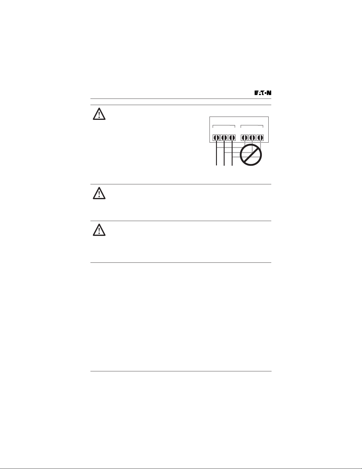
CAUTION!
Be sure not to connect an AC power supply
to the output terminals. Otherwise, there is
the danger of injury and/or fire.
Note:
L1, L2, L3: Three-phase 200 to 230V 50/60 Hz
Three-phase 380 to 460V 50/60 Hz
Three-phase 500 to 600V 50/60 Hz
Any two inputs:
Single-phase 100 to 120V 50/60 Hz;
Single-phase 200 to 240V 50/60 Hz
Power Input
L3L2L1
Power Output
T3
T2T1
CAUTION!
The operation of the inverter can be easily changed from low speed to
high speed. Be sure to check the capability and limitations of the
motor and machine before operating the inverter. Otherwise, there is
the danger of injury.
CAUTION!
If you operate a motor at a frequency higher than the inverter standard
default setting (50 Hz/60 Hz), be sure to check the motor and machine
specifications with the respective manufacturer. Only operate the
motor at elevated frequencies after getting their approval. Otherwise,
there is the danger of equipment damage.
MVX9000 User Manual xiii
Page 16

This page intentionally left blank.
xiv MVX9000 User Manual
Page 17

Chapter 1
Introduction
Inside this chapter …
How to Use This Manual . . . . . . . . . . . . . . . . . . . . . . 1-2
Intended Audience . . . . . . . . . . . . . . . . . . . . . . . . . . . 1-3
Conventions Used in This Manual . . . . . . . . . . . . . . 1-3
Warranty and Liability Information . . . . . . . . . . . . . . 1-4
Related Publications . . . . . . . . . . . . . . . . . . . . . . . . . . 1-4
Introduction
MVX9000 User Manual 1-1
Page 18

How to Use This Manual
This chapter describes the purpose and contents of this manual and the intended
audience. This chapter also explains conventions used in this manual and lists
related publications.
How to Use This Manual
Introduction
The purpose of this manual is to provide you with information necessary to
install, set parameters, troubleshoot and maintain the Cutler-Hammer
®
Adjustable Frequency Drives from Eaton’s electrical business. To guarantee safe
operation of the equipment, read the safety guidelines at the beginning of this
manual before connecting power to the AC motor drives. Keep this operating
manual handy and distribute to all users for reference.
Chapter 1 — Introduction is the chapter you are reading now.
Chapter 2 — Overview of the MVX9000 Drive describes receiving and inspection
procedures and provides an introduction to digital keypad operation.
Chapter 3 — Storage and Installation describes planning for drive installation
and drive mounting. This chapter also includes requirements and connections for
wiring.
Chapter 4 — Start-Up Procedures provides a detailed explanation of digital
keypad operation.
Chapter 5 — Descriptions of Parameter Settings provides detailed explanations
for all parameter settings.
Chapter 6 — Maintenance and Inspection describes maintenance procedures.
Chapter 7 — Troubleshooting and Fault Information lists the fault displays,
descriptions, and corrective actions.
Appendix A — Technical Data lists standard specifications.
Appendix B — Parameter Tables provides listing of all parameters with
descriptions, ranges and defaults.
Appendix C — Accessories provides information about circuit breakers, fuses,
braking resistors, and other accessories for the Cutler-Hammer MVX9000 Drives.
Appendix D — Dimensions displays keypad and drive dimensions.
Appendix E — is a Declaration of Conformity.
MVX9000
1-2 MVX9000 User Manual
Page 19

Intended Audience
Intended Audience
The audience for this manual has:
Knowledge of standard electrical wiring practices, electronic components,
•
and electrical schematic symbols.
The audience for this manual will install, start-up, and service the Cutler-Hammer
MVX9000 Drives.
Conventions Used in This Manual
Listed below are terms and language conventions used in this manual. These
terms and conventions are defined here to help you understand their meanings
and applications throughout this manual.
Digital Keypad Display
The Digital Keypad display is an LED readout of drive parameter selections and
drive operation status. Letters or numbers appear in the display according to
which keys you press.
Digital Keypad Keys
Digital Keypad keys are flat, labeled, pushbutton-type devices that allow you to
select drive parameters, and monitor drive operation.
Parameter
A parameter is selected through the Digital Keypad. Parameters in this manual
are expressed as Parameter Group Number, a decimal (.), and a Parameter
number.
Press
Press a key on the Digital Keypad Control Panel to select a parameter. Refer to
Chapter 2 — Overview of the MVX9000 Drive, Digital Keypad.
Introduction
MVX9000 User Manual 1-3
Page 20

Warranty and Liability Information
Warranty and Liability Information
Eaton Electrical Inc. warrants the product delivered in the Cutler-Hammer
shipping package to be free from defects in material and workmanship, under
normal use and service, for twenty four (24) months from date of manufacturing.
Products that fail during this period will be repaired or replaced at Eaton’s
Introduction
discretion, with the same or a functionally equivalent product, provided the
original purchaser (A) returns the failed product, and (B) provides proof of
original date of purchase. This warranty does not apply, in the judgment of
Eaton, to damage caused during shipment, handling, storage, or accidental
misuse. The original purchaser of the product must obtain a Cutler-Hammer
Return Material Authorization (RMA) number prior to returning any defective
product. (When purchased through an Authorized Distributor, the Distributor
should supply an RMA number to their customer.)
The maximum liability of this warranty is limited to the purchase price of the
product. In no event, regardless of cause, shall Eaton Electrical Inc. be liable (a)
for penalties or penalty clauses of any description, or (b) for certification not
otherwise specifically provided herein and/or indemnification of purchaser or
others for costs, damages or expenses, each arising out of or related to the
product or services of any order or (c) for any damages resulting from loss of
profits, use of products or for any incidental indirect or consequential damages,
even if advised of the possibility of such damages.
Related Publications
Brochure (Publication Numbers: BR04002001E)
Technical Document (Publication Numbers: TD04002001E)
Manual (Publication Number: TD04002003E)
Contact Name, Number:
Eaton Electrical Inc.
1000 Cherrington Parkway
Moon Township, PA 15108-4312
Tel: 1-800-525-2000
www.EatonElectrical.com
1-4 MVX9000 User Manual
Page 21

Chapter 2
Overview of the MVX9000 Drive
Inside this chapter …
Receiving and Inspection . . . . . . . . . . . . . . . . . . . . . . 2-2
Nameplate Information . . . . . . . . . . . . . . . . . . . . . 2-2
Catalog Number . . . . . . . . . . . . . . . . . . . . . . . . . . 2-2
Style Number . . . . . . . . . . . . . . . . . . . . . . . . . . . . . 2-3
External Parts and Label Locations . . . . . . . . . . . . . . 2-3
Digital Keypad Operation . . . . . . . . . . . . . . . . . . . . . . 2-4
Overview of the
MVX9000 Drive
MVX9000 User Manual 2-1
Page 22
Receiving and Inspection
Receiving and Inspection
This MVX9000 AC drive has gone through quality control tests at the factory before
shipment. After receiving the AC motor drive, please check for the following:
Check to make sure that the package includes an AC drive and User Manual.
•
Inspect the unit to insure it was not damaged during shipment.
•
Make sure that the part number indicated on the nameplate corresponds with
•
the part number of your order.
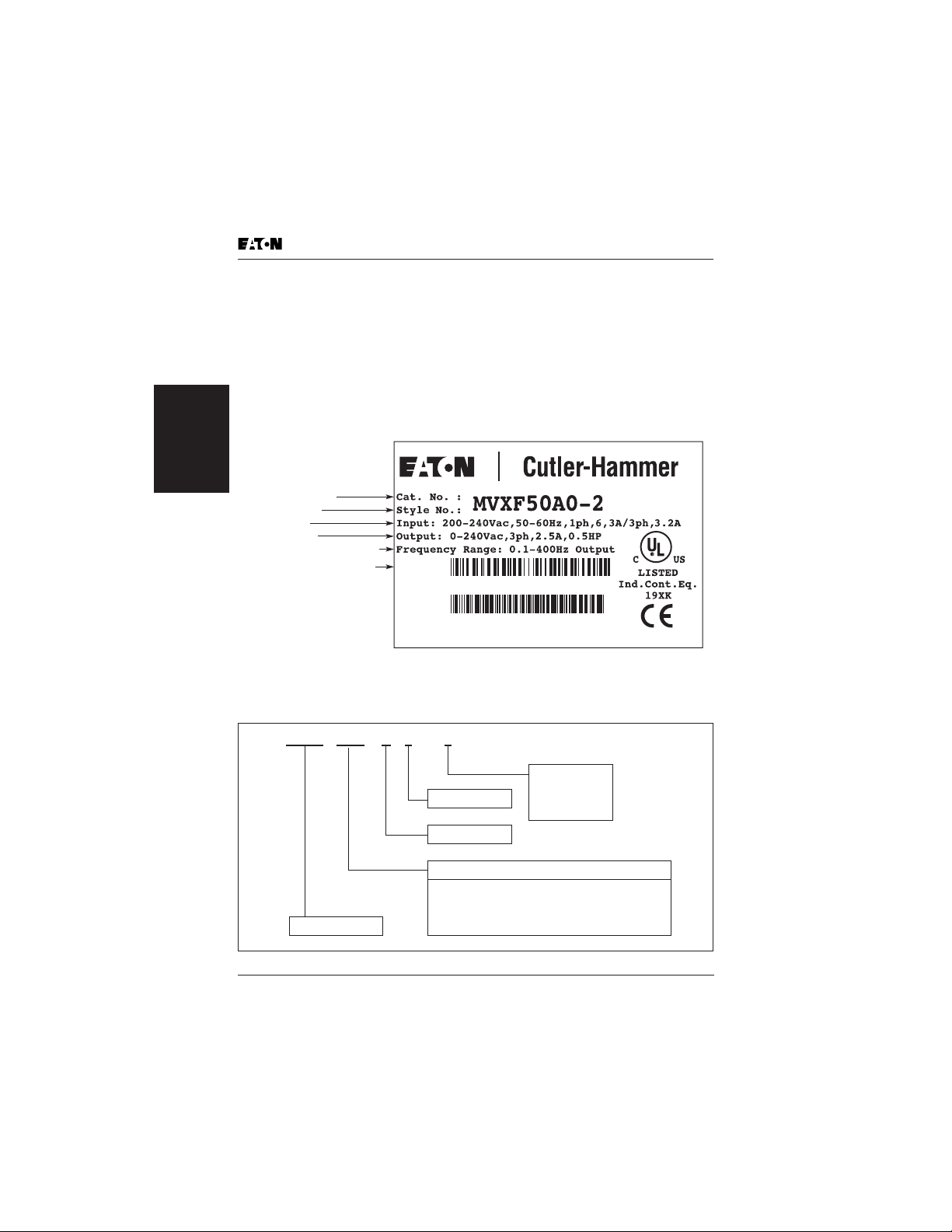
Nameplate Information
MVX9000 Drive
Overview of the
Catalog Number
Style Number
Input Spec.
Output Spec.
Output Frequency Range
Serial Number Bar Code
MADE IN XXXXXXX
Figure 2-1: Example of 1/2 hp 230V AC drive
Catalog Number
Table 2-1: MVX9000 Catalog Numbering System
M V X F 5 0 A0 -2
Enclosure
Version Type
F25 = 1/4 hp (0.2 kW)
F50 = 1/2 hp (0.4 kW)
Model Number
001 = 1 hp (0.7 kW)
002 = 2 hp (1.5 kW)
10782116036223
F50A02T2410002
1 = 115V AC
2 = 240V AC
4 = 480V AC
5 = 575V AC
Motor Horsepower
003 = 3 hp (2.2 kW)
005 = 5 hp (3.7 kW)
007 = 7-1/2 hp (5.5 kW)
010 = 10 hp (7.5 kW)
2-2 MVX9000 User Manual
Page 23
External Parts and Label Locations
Style Number
The style number contains the same information as the Catalog Number, and is
used internally for ordering purposes.
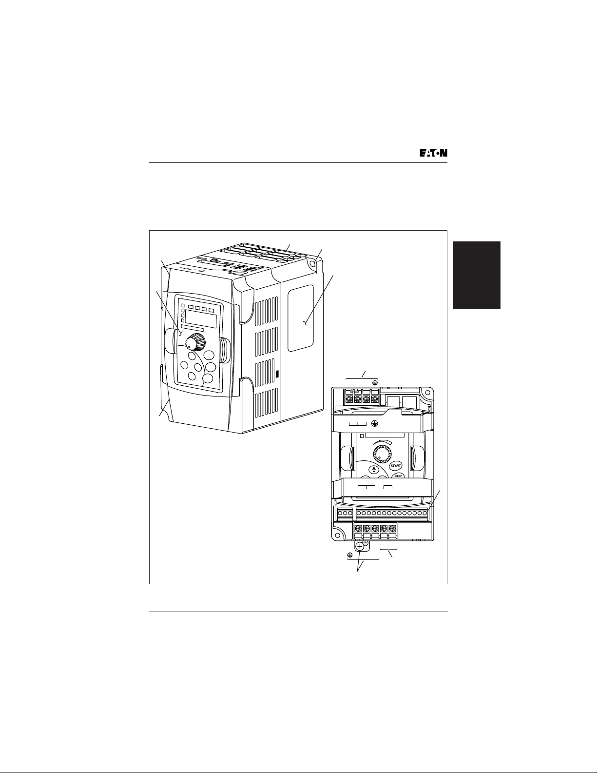
External Parts and Label Locations
6
5
L1
L2
L3
LI
N
E
1
Overview of the
MVX9000 Drive
2
4
7
L1 L2 L3
3
1
Mounting Screw Holes
2
Nameplate Label
3
Bottom Door
4
Digital Keypad
5
Upper Door
6
Ventilation Holes
7
L1, L2, L3, Input Terminals
8
Control Input/Output Terminals
9
B1, B2 External Braking Resistor
10
, T1, T2, T3 Output Terminals
L1 L2 L3
LINE
MOTOR Braking
T1 T2
T3 B1 B2
8
B1 B2
T1 T2 T 3
9
10
Figure 2-2: Parts and Label
MVX9000 User Manual 2-3
Page 24
Digital Keypad Operation
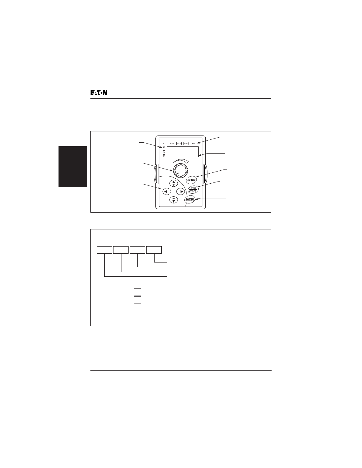
Digital Keypad Operation
The digital keypad includes the display panel and the keypad. The display panel
provides the parameter display and shows the operation status of the AC drive.
The keypad provides programming and control interface.
LED Indicators
LED Indicators
Lamp Lights to Indicated
Frequency Input, Hz Output,
Amps and User Defined Units
Potentiometer
For Setting
Input Speed Command
MVX9000 Drive
Overview of the
Up, Down and
Right/Left Keys
Scrolls Display,
Enter/Exit Parameter Mode,
Change Parameter Settings
LED Displays
RUN STOP FWD REV
Figure 2-3: Description of Digital Keypad
Green lamp lights during REV operation.
Green lamp lights during FWD operation.
Red lamp lights by pressing STOP.
Green lamp lights by pressing RUN.
Lamp Lights During Run,
Stop, Fwd, Rev Operations
LED Display
Indicates Motor and
Drive Parameter
START Key
Start Command
STOP/RESET Key
Stop Command and Reset
the Drive After a Fault Occurs
ENTER Key
Used in Parameter Mode
to Enter and Change Values
Lamp lights to indicate input frequency reference
F
Lamp lights to indicate output Hz
H
Lamp lights to indicate output amps
A
Lamp lights to indicate user defined units
U
Figure 2-4: Explanation of the LED Indicators
2-4 MVX9000 User Manual
Page 25
Digital Keypad Operation
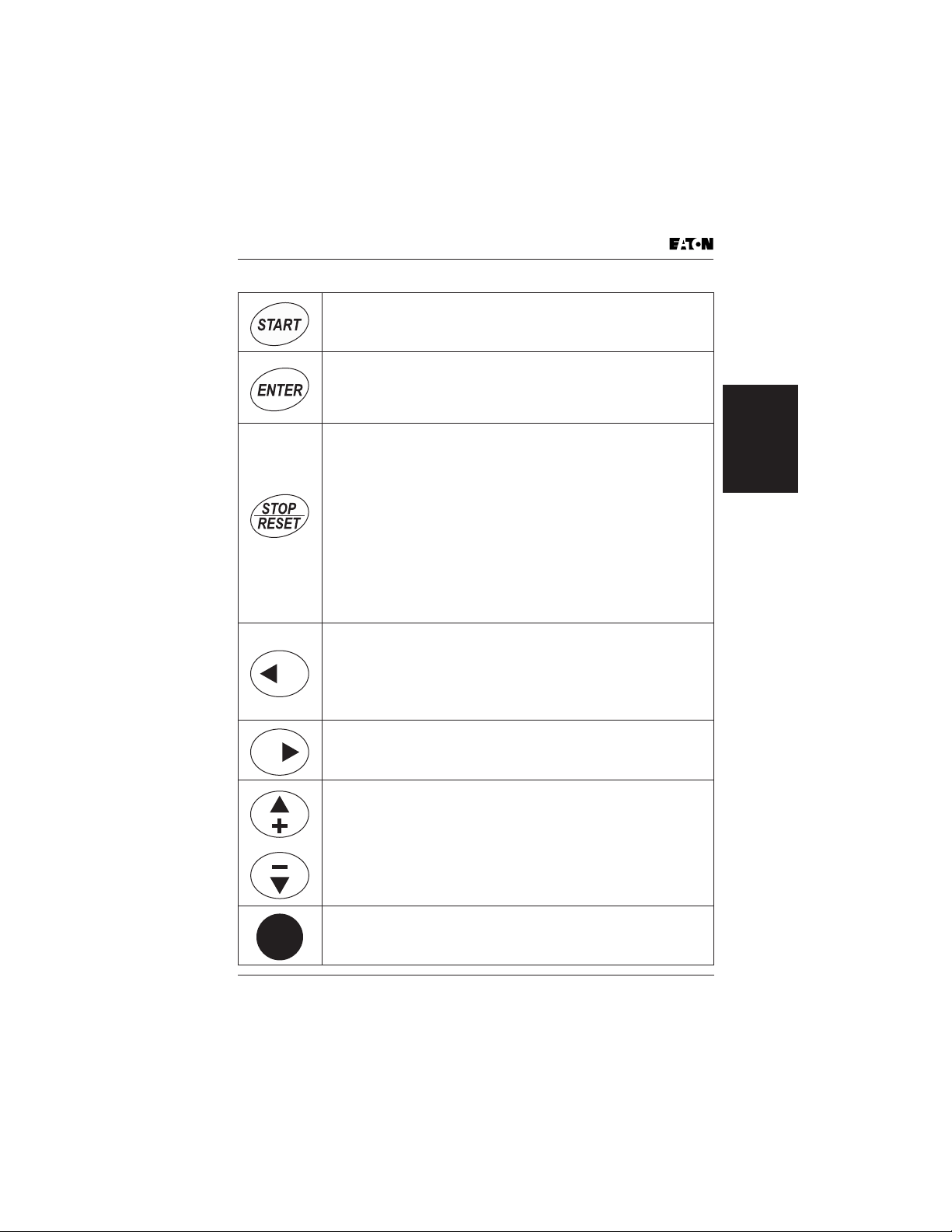
Table 2-2: Keypad Operators
START
This button operates as Start button for normal operation
• Motor START from the panel; active control place has to be
selected at “Panel”
ENTER
This button in the parameter edit mode is used to enter the
programming mode and enter the parameter selection.
• used for parameter edit confirmation, acceptance (confirmation)
of the edited parameter value with exit from parameter edit mode
STOP / RESET
This button has two integrated operations. The button operates as
Stop button for normal operation. In the parameter edit mode it is
used to cancel previous action and back-up one step, and in fault
mode it is used to reset the fault.
STOP
• motor STOP from the panel; active control place has to be
selected at “Panel”
RESET
• used for active fault resetting
- fault history is reset if ENTER is pressed on the “Fault History”
menu group in “Main Menu” or
- if ENTER is pressed while in the “Fault History” menu
• in programming mode press RESET key to cancel previous action
and back up one step
LEFT Arrow
• navigation button, movement to left
• in display mode, enter parameter group mode
• in parameter edit mode, exits mode, backs up one step
• cancels edited parameter (exit from a parameter edit mode)
Overview of the
MVX9000 Drive
RIGHT Arrow
• navigation button, movement to right
• enter parameter group mode
• enter parameter mode from group mode
UP and DOWN Arrows
• move either up or down the group list in order to select the
desired group menu.
• move either up or down the parameter list in order to select the
desired parameter in the group.
• increasing/decreasing of reference value on the keyboard (when
selected).
SPEED POT
• increase/decrease reference value on the keypad (when selected)
MVX9000 User Manual 2-5
Page 26
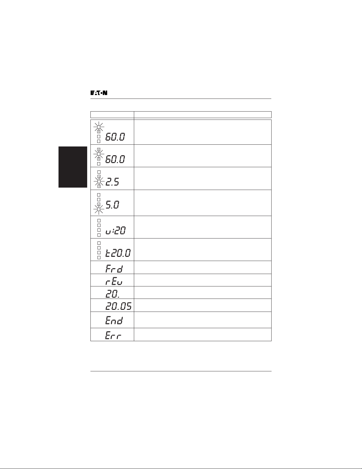
Table 2-3: Explanation of Display Messages
Displayed Message Descriptions
F
The AC drive Input Frequency Reference.
The Actual Operation Frequency at the output terminals T1, T2
H
and T3.
The output current present at the output terminals T1, T2 and T3.
MVX9000 Drive
Overview of the
A
The value of the user defined units.
U
The output voltage present at the output terminals T1, T2 and T3.
The temperature of the unit.
The AC drive forward run status.
Digital Keypad Operation
The AC drive reverse run status.
Parameter group selection.
The specific parameter selection.
“End” displays for approximately 1 second if input has been
accepted. After a parameter value has been set, the new value is
automatically stored in memory.
“Err” displays, if the input is invalid.
2-6 MVX9000 User Manual
Page 27

Chapter 3
Storage and Installation
Inside this chapter …
Storage . . . . . . . . . . . . . . . . . . . . . . . . . . . . . . . . . . . . 3-2
Environment . . . . . . . . . . . . . . . . . . . . . . . . . . . . . . . . 3-2
Operation . . . . . . . . . . . . . . . . . . . . . . . . . . . . . . . . 3-2
Storage . . . . . . . . . . . . . . . . . . . . . . . . . . . . . . . . . . 3-2
Transportation . . . . . . . . . . . . . . . . . . . . . . . . . . . . 3-2
Pollution Degree . . . . . . . . . . . . . . . . . . . . . . . . . . 3-2
Mounting Area . . . . . . . . . . . . . . . . . . . . . . . . . . . . . . 3-3
Wiring . . . . . . . . . . . . . . . . . . . . . . . . . . . . . . . . . . . . . 3-4
Applicable Codes . . . . . . . . . . . . . . . . . . . . . . . . . . . . 3-4
Basic Wiring Diagram . . . . . . . . . . . . . . . . . . . . . . . . . 3-5
External Wiring . . . . . . . . . . . . . . . . . . . . . . . . . . . . . . 3-6
Control Terminal Wiring (Factory Settings) . . . . . . . . 3-7
Main Circuit Wiring . . . . . . . . . . . . . . . . . . . . . . . . . . . 3-8
Wiring Notes . . . . . . . . . . . . . . . . . . . . . . . . . . . . . . . . 3-9
Motor Operation Precautions . . . . . . . . . . . . . . . . . . 3-10
Storage and
Installation
MVX9000 User Manual 3-1
Page 28

Storage
The AC drive should be stored in the shipping carton before installation. In order
to retain the warranty coverage, the AC drive should be stored properly when it is
not to be used for an extended period of time. Some storage suggestions are:
• Store in a clean and dry location free from direct sunlight or corrosive fumes.
• Store within an ambient temperature range of -20 to +60°C.
• Store within a relative humidity range of 0 to 90% and non-condensing
environment.
• Store within an air pressure range of 86 to 106 kPA.
Environment
Operation
Air Temperature: 1/2 hp – 5 hp -10 to +50°C (14 to 122°F)
Relative Humidity: 0% to 90%, no condensation allowed
Atmosphere Pressure: 86 to 106 kPa
Installation Site Altitude: below 1000m
Installation
Storage and
Vibration: Maximum 9.80 m/s2 (1G) at less than 20 Hz
Storage
Temperature: -20 to +60°C (-4 to 140°F)
Relative Humidity: Less than 90%, no condensation allowed
Atmosphere Pressure: 86 to 106
7-1/2 hp – 10 hp: -10 to +40°C (14 to 104°F)
Maximum 5.88 m/s2 (0.6G) at 20 to 50 Hz
Storage
Transportation
Temperature: -20 to +60°C (-4 to 140°F)
Relative Humidity: Less than 90%, no condensation allowed
Atmosphere Pressure: 86 to 106 kPa
Vibration: Maximum 9.80 m/s2 (1G) at less than 20 Hz,
Maximum 5.88 m/s2 (0.6G) at 20 to 50 Hz
Pollution Degree
UL Type 0, Pollution Degree 2: good for a factory type environment
Relative Humidity: Less than 90%, no condensation allowed
Atmosphere Pressure: 86 to 106
3-2 MVX9000 User Manual
Page 29
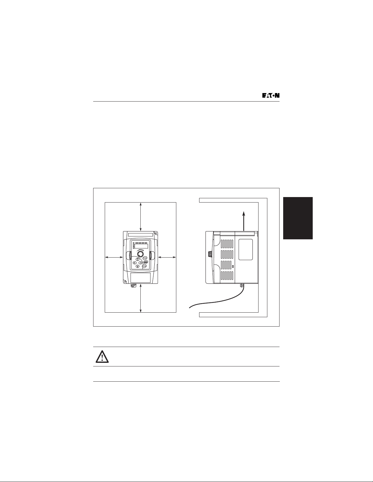
Mounting Area
Mounting Area
Improper installation of the AC drive will greatly reduce its life. Be sure to
observe the following precautions when selecting a mounting location. Failure to
observe these precautions may void the warranty!
Do not mount the AC drive near heat-radiating elements or in direct sunlight.
Do not install the AC drive in a place subjected to high temperature, high
humidity, excessive vibration, corrosive gases or liquids, or airborne dust or
metallic particles.
Mount the AC drive vertically and do not restrict the air flow to the heatsink fins.
The AC drive generates heat. Allow sufficient space around the unit for heat
dissipation as shown in the figure below:
3.0 (76)
or More
Air Flow
Storage and
Installation
3.0 (76)
or More
1.0 (25)
or More
1.0 (25)
or More
Figure 3-1: Mounting in an Enclosure in Inches (mm)
When mounting in an enclosure, allow for the recommended free
space. Failure to allow adequate air flow may result in drive over
temperature.
MVX9000 User Manual 3-3
Page 30
Wiring
DANGER!
Hazardous Voltage
Before opening the AC drive covers:
• Disconnect all power to the AC drive.
Wait five minutes for DC bus capacitors discharge.
Any electrical or mechanical modification to this equipment without prior
written consent of Eaton will void all warranties and may result in a safety
hazard in addition to voiding the UL listing.
Short Circuit Withstand: The rated voltage for AC motor drive must be equal or
less than 240V (equal or less than 480V for 460V models, equal or less than 600V
for 575V models) and the mains supply current capacity must be equal or less
than 5000A RMS (equal or less than 10000A RMS for the 40 hp [30 kW] models).
Applicable Codes
All Cutler-Hammer MVX9000 AC drives are Underwriters Laboratories, Inc. (UL)
and Canadian Underwriters Laboratories (cUL) listed, and therefore comply with
the requirements of the National Electrical Code (NEC) and the Canadian
Electrical Code (CEC).
Installation
Storage and
Installation intended to meet the UL and cUL requirements must follow the
instructions provided in “Wiring Notes” as a minimum standard. Follow all local
codes that exceed UL and cUL requirements. Refer to the technical data label
affixed to the AC drive and the motor nameplate for electrical data.
The “Line Fuse Specification” in Appendix C lists the recommended fuse part
number for each MVX9000 part number. These fuses (or equivalent) must be
used on all installations where compliance with UL standards is required.
According to the Low Voltage Directive 73/23/EEC and the Amendment Directive
93/68/EEC Digital Keypad, the following AC Motor Drives, MVXF50A0-2,
MVX001A0-2, MVX002A0-2, MVX003A0-2, MVX005A0-2, MVX007A0-2,
MVX001A0-4, MVX002A0-4, MVX003A0-4, MVX005A0-4, MVX007A0-4,
MVX010A0-4, are herewith confirmed to comply with the requirements set out in
the Council Directive 73/23/EEC for electrical equipment used within certain
voltage limits and the Amendment Directive 93/68/EEC. For the evaluation of the
compliance with this Directive, the following standard was applied: EN 50178.
According to the Electromagnetic Compatibility 89/336/EEC and the Amendment
Directive 93/68/EEC, the following equipment, AC Motor Drive, MVXF50A0-2,
MVX001A0-2, MVX002A0-2, MVX003A0-2, MVX005A0-2, MVX007A0-2,
MVX001A0-4, MVX002A0-4, MVX003A0-4, MVX005A0-4, MVX007A0-4,
MVX010A0-4, is herewith confirmed to comply with the requirements set out
in the Council Directive 89/336/EEC for electromagnetic compatibility and the
Amendment Directive 93/68/EEC. For the evaluation of the compliance with
this Directive, the following standards were applied: EN61800-3, EN55011,
EN50081-2, EN50082-2, EN61000-4-2, EN61000-4-3, EN61000-4-4, EN61000-4-5,
EN61000-4-6, EN61000-4-8.
Wiring
3-4 MVX9000 User Manual
Page 31

Basic Wiring Diagram
Basic Wiring Diagram
Users must connect wiring according to Figure 3-2.
Braking Resistor
(Please see Appendix C for Detail)
Main Circuit Power
NFB
R/L1
S/L2
T/L3
Forward/Stop
Reverse/Stop
Pre-Set 1
Pre-Set 2
Pre-Set 3
Reset
Common Signal
Master Frequency Setting
Factory Default Is Potentiometer
Which Is on the Digital Keypad
Analog Voltage
Potentiometer:
Factory Default
3
0 –10V DC
3 – 5 KΩ
Analog
Current
4 – 20 mA
NOTE: Do not plug a modem or telephone line to the RS-485 communication
port, permanent damage may result. Terminals 2 & 5 are the power
sources for the optional copy keypad and should not be used while
using RS-485 communication.
• 1/2 – 3 hp 230V MVX9000 drives are both single- and three-phase input ready.
For single-phase input models, select any two input power terminals. For
three-phase input, use all three power input terminals.
VR
2
1
(Optional)
B1
R/L1
S/L2
T/L3
DI1
DI2
DI3
DI4
DI5
DI6
COM
+10V 10 mA (Max)
AI1 (POT)
AI2 (Current)
COM
RS-485
Series
Interface
B2
U/T1
V/T2
W/T3
RO3
RO1
RO2
DO1
DOC
AO+
COM-
RJ-12
6 1
Grounding Resistance
230V: Less Than 100Ω
460V: Less Than 10Ω
575V: Less Than 100Ω
NO Relay Output
(120V AC/24V DC 5A)
NC Relay Output
(120V AC/24V DC 5A)
Factory Default: Inverter
Fault
Digital Output
(48V DC 50 mA)
Factory Default: Inverter
Running
Factory Default:
Output Frequency
1,6: NC
2: GND
3: SG4: SG+
5: +EV
AC
Motor
VR(1 KΩ)
If Adjustment
Needed
Analog
+
–
DC 0 – 10V
Main Circuit
(Power)
Te rm inals
Control Circuit
Te rm inals
Shielded
Leads
Output
Storage and
Installation
Figure 3-2: Circuit Diagram
MVX9000 User Manual 3-5
Page 32

External Wiring
External Wiring
Power Supply
Installation
Storage and
EMI Filter
L1
T1
L2
LINE
MOTOR
T2
Fuse
Magnetic
Contactor
Line Reactor
L3
B2
T3
Load
Reactor
B1
Braking
Resistor
Table 3-1: Wiring Items
Items Explanations
Input
Power
Please follow the specific
power supply requirement
shown in Appendix A.
Fuse Please check the Fuse
Specification table in
Appendix C for proper fuse
selection.
Magnetic
Contactor
(Optional)
Please do not use a Magnetic
Contactor as the ON/OFF
switch of the AC drive, this
will reduce the operating life
of the AC drive. The
contactor should only be
used as a safety device for
disconnecting power to the
drive.
Line/Load
Reactor
(Optional)
To improve the power factor.
An AC Reactor may be
necessary when capacity is
above 1000 kVA, and the
wiring distance is within 10m.
EMI Filter
(Optional)
Used to reduce the
electromagnetic
interference.
Braking
Resistor
(Optional)
Used to reduce stopping
time of the motor. Please
refer to the Breaking Resistor
table in Appendix C for
specific Braking Resistors.
Note: Please refer to Appendix C for
more details on the Circuit Breaker and
Fuse Specification tables.
Motor
Figure 3-3: External Wiring
3-6 MVX9000 User Manual
Page 33

Control Terminal Wiring (Factory Settings)
Control Terminal Wiring (Factory Settings)
RO3 RO2 RO1
NO
Relay Output
Factory Setting
NC Relay Output
Run/Stop
Reverse/Forward
Preset Speed 1
Preset Speed 2
Preset Speed 3
Reset
DI1 DI2
DI3
DI4
DI5
DI6
COM
AO+
AI1
Bias
Potentiometer
Full scale voltmeter
0 to 10V DC
Factory Setting:
Output Frequency
+10V
4–20 mA
AI2
COM
DO1DOC
Factory Setting:
Inverter Running
Digital Output
Figure 3-4: Control Terminal Wiring (Factory Settings)
Note: For Wire Gauge and Torque tightening specifications, please refer to
Table 3-3.
Table 3-2: Terminal Symbols
Terminal
Symbols Terminal Name Remarks
R01 - R02 Digital Output Relay Refer to 40.04 Relay output contact
R03 - R02 Digital Output Relay
RO1 - RO2 (NC Contact)
RO3 - RO2 (NO Contact)
D01 - DCM Digital photocouple output Refer to 40.03
RJ-12 Serial communication port RS-485 serial communication interface
+10V - COM Power Supply (+10V)
AI1 - COM
AI2 - COM
AO+ - COM Analog frequency/current
Analog voltage input
Analog current input
0 to +10V Input
0 to 20 mA or 4 to 20 mA Input
0 to +10V Output
meter
DI1 - COM Digital input 1 Refer to 30.11
DI1 - COM
to
DI6 - GND
Digital input 2
to
Digital input 6
Storage and
Installation
MVX9000 User Manual 3-7
Page 34

Main Circuit Wiring
L1 L2 L3
L1 L2
LINE
MOTOR Braking
T1 T2
Installation
Storage and
Table 3-3: Wire Gauge and Torque Tightening
Wire Type: 75ºC Copper Only
Catalog Number
MVXF25A0-1 (1-phase)
MVXF50A0-1 (1-phase)
MVX001A0-1 (1-phase)
MVXF50A0-2 (1-phase)
MVXF50A0-2 (3-phase)
MVX001A0-2 (1-phase)
MVX001A0-2 (3-phase)
MVX002A0-2 (1-phase)
MVX002A0-2 (3-phase)
MVX003A0-2 (1-phase)
MVX003A0-2 (3-phase)
MVX005A0-2
MVX007A0-2
T1
Figure 3-5: Main Circuit
Voltage
Horsepower
115V AC, 1/4 hp
115V AC, 1/2 hp
115V AC, 1 hp
240V AC, 1/2 hp
240V AC, 1/2 hp
240V AC, 1 hp
240V AC, 1 hp
240V AC, 2 hp
240V AC, 2 hp
240V AC, 3 hp
240V AC, 3 hp
240V AC, 5 hp
240V AC, 7-1/2 hp
L3
T3 B1 B2
T2 T3
B1
B2
Max. Current (A)
(Input/Output)
16/4.2
6.3/2.5
3.2/2.5
11.5/5
15.7/7
19.6/17
6/1.6
9/2.5
6.3/5
9/7
27/10
15/10
28/25
Main Circuit Wiring
Wire
Gauge
(AWG)
Torque
Rating
(kgf-cm)
12 – 14
12 – 14
14
12
12 – 14
12 – 14
12 – 14
12 – 14
14
12
12 – 14
8
8 – 12
8 – 10
15
8
3-8 MVX9000 User Manual
Page 35

Wiring Notes
Table 3-3: Wire Gauge and Torque Tightening, continued
Wire Type: 75ºC Copper Only
Catalog Number
MVX001A0-4
MVX002A0-4
MVX003A0-4
MVX005A0-4
MVX007A0-4
MVX010A0-4
MVX001A0-5 575V AC, 1 hp 1.7A/2.4A
MVX003A0-5 575V AC, 3 hp 4.2A/5.9A
MVX005A0-5 575V AC, 5 hp 6.6A/7.0A
MVX010A0-5 575V AC, 10 hp 12.2A/12.9A 8 – 12
Voltage
Horsepower
480V AC, 1 hp
480V AC, 2 hp
480V AC, 3 hp
480V AC, 5 hp
480V AC, 7-1/2 hp
480V AC, 10 hp
Max. Current (A)
(Input/Output)
4.2/3
5.6/4
6/5
8.5/8.2
14/13
23/18
Wire
Gauge
(AWG)
12 – 14
12 – 14
12 – 14
8 – 14
8 – 12
8 – 10
12 – 14 14MVX002A0-5 575V AC, 2 hp 3.0A/4.2A
8 – 14
Torque
Rating
(kgf-cm)
14
15
15MVX007A0-5 575V AC, 7-1/2 hp 9.9A/10.5A
Wiring Notes
Please read prior to Installation
CAUTION!
Do not connect the AC power to the T1, T2, T3 terminals, it will
damage the AC drive.
WARNING!
Make sure that all screws are tightened to the proper torque rating
shown in Table 3-3.
• During installation, follow all local electrical, construction, and safety codes
for the country in which the drive is installed.
• Make sure that the appropriate protective devices (circuit breaker or fuses)
are connected between the power supply and AC drive.
• Make sure that the leads are connected correctly and the AC drive is properly
grounded.
• Use ground leads that comply with AWG/MCM standards and keep them as
short as possible.
• Multiple MVX9000 units can be installed in one location. All the units should
be grounded directly to a common ground terminal. The MVX9000 ground
terminals may also be connected in parallel, as shown in the Figure 3-6.
Make sure there are no ground loops.
Storage and
Installation
MVX9000 User Manual 3-9
Page 36

Motor Operation Precautions
Ye s Ye s No
Figure 3-6: Parallel Grounding
• When the AC drive output terminals U/T1, V/T2 and W/T3 are connected to
the motor terminals T1, T2 and T3, respectively, the motor will rotate
counterclockwise (as viewed from the shaft ends of the motor) when a
forward operation command is received. To reverse the direction of motor
rotation, switch over any of the two motor leads.
• Make sure that the power source is capable of supplying the correct voltage
and required current to the AC drive.
• Do not attach or remove wiring when power is applied to the AC drive.
• Do not inspect components unless the inside “POWER” lamp has turned off.
• Do not monitor the signals on the circuit board while the AC drive is in
operation.
• For the single-phase rated AC drives, the AC power can be connected to any
Installation
Storage and
two of the three input terminals R/L1, S/L2, T/L3. Note: This drive is not
intended for use with single-phase motors.
• Route the power and control wires separately, or at a 90 degree angle to each
other.
• If a filter is required for reducing EMI (Electro Magnetic Interference), install it
as close as possible to the AC drive. EMI can also be reduced by lowering the
Carrier Frequency.
• If the AC drive is installed in the place where a load reactor is needed, install
the filter close to U/T1, V/T2, W/T3 side of AC drive. Do not use a Capacitor or
L-C Filter (Inductance-Capacitance) or R-C Filter (Resistance-Capacitance),
unless approved by Eaton.
• When using a GFCI (Ground Fault Circuit Interrupt), select a current sensor
with sensitivity of 200 mA, and not less than 0.1-second detection to avoid
nuisance tripping.
Motor Operation Precautions
• When using the AC drive to operate a standard 3-phase induction motor,
notice that the energy loss is greater than for an inverter duty motor.
• Avoid running a standard induction motor at low speed. Under these
conditions, the motor temperature may rise above the motor rating due to
limited airflow produced by the motor’s fan.
• When the standard motor operates at low speed, the output load must be
decreased.
• If 100% output torque is desired at low speed, it may be necessary to use a
special “inverter-duty” rated motor.
Forward
Running
3-10 MVX9000 User Manual
Page 37

Chapter 4
Start-Up Procedures
Inside this chapter …
Step-by-Step Installation . . . . . . . . . . . . . . . . . . . . . . 4-2
Mounting Location . . . . . . . . . . . . . . . . . . . . . . . . 4-2
Inverter Mounting . . . . . . . . . . . . . . . . . . . . . . . . . 4-4
Wiring Preparation . . . . . . . . . . . . . . . . . . . . . . . . 4-5
Wire Sizes . . . . . . . . . . . . . . . . . . . . . . . . . . . . . . . . 4-6
Fuses and Circuit Breakers . . . . . . . . . . . . . . . . . . . . . 4-7
Fusing . . . . . . . . . . . . . . . . . . . . . . . . . . . . . . . . . . . 4-7
Manual Motor Starters/UL489
Circuit Breakers . . . . . . . . . . . . . . . . . . . . . . . . . . . 4-7
Wiring the Inverter to Incoming Power . . . . . . . . 4-9
Wiring the Motor to the Inverter Output . . . . . . . 4-10
Power-Up Test . . . . . . . . . . . . . . . . . . . . . . . . . . . . 4-11
Powering the Inverter . . . . . . . . . . . . . . . . . . . . . . 4-12
Procedures
Start-Up
MVX9000 User Manual 4-1
Page 38

Step-by-Step Installation
This chapter will explain the installation of the MVX9000 Microdrive. Be sure to
read and follow all instructions for a successful installation.
WARNING!
This equipment should be installed, adjusted, and serviced by qualified
electrical maintenance personnel familiar with the construction and
operation of the equipment and the hazards involved. Failure to
observe this precaution could result in bodily injury.
Step-by-Step Installation
1. Read all instructions and warnings associated with mounting the MVX9000.
2. Select a suitable mounting location.
3. Check the inverter mounting dimensions for footprint and mounting hole
locations.
4. Connect the wiring for the inverter input.
5. Connect the wiring to the motor.
6. Perform a power-up test.
7. Make observations and re-check the installation.
Mounting Location
Step 1: Study the following caution messages associated with mounting the
inverter.
CAUTION!
Be sure to install the unit on flame-resistant material such as a steel
Start-Up
Procedures
plate. Otherwise, there is the danger of fire.
CAUTION!
Be sure to install the unit on a perpendicular wall which is not subject
to vibration. Otherwise, it may fall and cause injury to personnel.
CAUTION!
Be sure not to let the foreign matter enter vent openings in the
inverter housing, such as wire clippings, spatter from welding, metal
shavings, dust, etc. Otherwise, there is the danger of fire.
4-2 MVX9000 User Manual
Page 39

Step-by-Step Installation
CAUTION!
Be sure not to install or operate an inverter which is damaged or has
missing parts. Otherwise, it may cause injury to personnel.
CAUTION!
Be sure to install the inverter in a well-ventilated room which does not
have direct exposure to sunlight, a tendency for high temperature,
high humidity or dew condensation, high levels of dust, corrosive gas,
explosive gas, inflammable gas, grinding-fluid mist, salt damage, etc.
Otherwise, there is the danger of fire.
Step 2: The installation should be made on a solid, non-flammable, vertical
surface that is a relatively clean and dry environment. In order to ensure enough
room for air circulation around the inverter to aid in cooling, maintain the
specified clearance around the inverter specified in Figure 4-1.
3.0 (76)
1.0 (25)
or More
or More
1.0 (25)
or More
Air Flow
Procedures
Start-Up
3.0 (76)
or More
Figure 4-1: Clearances and Air Flow in Inches (mm)
MVX9000 User Manual 4-3
Page 40

Step-by-Step Installation
Please observe this checklist while mounting the inverter:
• The ambient temperature must be in the range of -10 to 50ºC (1/2 to 5 hp).
• The ambient temperature must be in the range of -10 to 40ºC (7-1/2 to 10 hp).
If the range will be up to 50ºC, set the carrier frequency to 2.1 kHz or less and
derate the output current to 80% or less. Chapter 5 covers how to change
parameters such as the carrier frequency.
• Keep any other heat-producing equipment as far away from the inverter as
possible.
• When installing the inverter in an enclosure, maintain the clearance around
the inverter and verify that its ambient temperature is within specification
when the enclosure door is closed.
• Do not open the main front panel door at any time during operation.
Step 3: Before proceeding to the wiring section, temporarily cover the inverter’s
ventilation openings. Paper and masking tape is all that is needed to do this. This
will prevent harmful debris such as wire clippings and metal shavings from
entering the inverter during installation.
Inverter Mounting
Step 4: Locate the applicable drawing in the Appendix for the inverter unit.
Dimensions are given in inches (millimeters) format.
Note: Some inverter housings require two mounting screws, while others require
four. Be sure to use lockwashers or other means to ensure screws do not loosen
due to vibration.
Start-Up
Procedures
4-4 MVX9000 User Manual
Page 41

Step-by-Step Installation
Wiring Preparation
Step 5: It is very important to perform the wiring steps carefully and correctly.
Before proceeding, please study the caution and warning messages below.
WARNING!
Use 75ºC Cu wire only or equivalent.
WARNING!
The rated voltage for AC motor drive must be equal or less than
240V (equal or less than 480V for 460V models, equal or less than
600V for 575V models) and the mains supply current capacity must
be equal or less than 5000A RMS (equal or less than 10000A RMS
for the 40 hp [30 kW] models).
HIGH VOLTAGE!
Be sure to ground the unit. Otherwise, there is danger of electric shock
and/or fire.
HIGH VOLTAGE!
Wiring work shall be carried out only by qualified personnel.
Otherwise, there is a danger of electric shock or fire.
Procedures
Start-Up
MVX9000 User Manual 4-5
Page 42

Step-by-Step Installation
Wire Sizes
The maximum motor currents in the application determine the recommended
wire size. The following table gives the wire size in AWG. The Power/Motor
column applies to the inverter input power, output wires to the motor, the ground
connection, and any other component shown in the system wiring diagram. The
“Signal Lines” column applies to any wire connecting to the External I/O
Connection inside the bottom front panel half-door.
Table 4-1: Wire Size
Motor Output
(kW/hp)
kW hp Power Lines Signal Lines
0.2
0.4
0.75
0.4
0.75
1.5
1.5
2.2
2.2
3.7
5.5
0.75
1.5
2.2
4.0
5.5
7.5
Start-Up
Procedures
0.75 1 MVX001A0-5 AWG 14 / 2.1 mm
1/4
1/2
1
1/2
1
2
2
3
3
5
7-1/2
1
2
3
5
7-1/210MVX007A0-4
Inverter Model
MVXF25A0-1
MVXF50A0-1
MVX001A0-1
MVXF50A0-2
MVX001A0-2
MVX001A0-2 (1-phase)
MVX002A0-2 (3-phase)
MVX003A0-2 (1-phase)
MVX003A0-2 (3-phase)
MVX005A0-2
MVX007A0-2
MVX001A0-4
MVX002A0-4
MVX003A0-4
MVX005A0-4
MVX010A0-4
AWG 14 / 2.1 mm
AWG 14 / 2.1 mm
AWG 12 / 3.3 mm
AWG 14 / 2.1 mm
AWG 14 / 2.1 mm
AWG 12 / 3.3 mm
AWG 14 / 2.1 mm
AWG 8 / 8.4 mm
AWG 12 / 3.3 mm
AWG 10 / 5.3 mm
AWG 8 / 8.4 mm
AWG 14 / 2.1 mm
AWG 12 / 3.3 mm
AWG 10 / 5.3 mm
1.5 2 MVX002A0-5
2.2 3 MVX003A0-5
3.7 5 MVX005A0-5
5.5 7-1/2 MVX007A0-5
7.5 10 MVX010A0-5 AWG 12 / 3.3 mm
Wiring
2
(*) 24 to 12 AWG /
2
0.2 to 3.3 mm
2
shielded wire
2
2
2
2
2
2
2
2
2
2
2
2
2
2
Note 1: Field wiring must be made by a UL-listed and CSA-certified closed-loop
terminal connector sized for the wire gauge involved.
Note 2: Be sure to consider the capacity of the circuit breaker to be used.
Note 3: Be sure to use larger wires for the power lines in the distance exceeds 20
meters.
4-6 MVX9000 User Manual
Page 43

Fuses and Circuit Breakers
Fuses and Circuit Breakers
The MVX9000 does not provide branch short circuit protection. This product
should be installed with either input fuses or an input circuit breaker. National
and local industrial safety regulations and/or electrical codes may determine
additional requirements for these installations.
Note: To guard against personal injury and/or equipment damage caused by
improper fusing or circuit breaker selection, use only the recommended line
fuses/circuit breakers specified in this section.
Fusing
The MVX9000 has been UL tested and approved for use with input fuses. The
ratings in Table 4-2 are the minimum recommended values for use with each
drive rating. The devices listed in this table are provided to serve as a guide.
Other devices which meet the requirements of UL508C and UL489 with similar
trip characteristics may be used in order to meet local or national electrical
codes.
Manual Motor Starters/UL489 Circuit Breakers
When using manual motor starters or UL489 rated circuit breakers, follow
manufacturer’s recommended guidelines for installation.
Table 4-2: Fuse Specification Chart
Input
(A)
Output
Current
(A)
Model
F25A0-1 6 1.6 15 JJN-15 XTPR010BC1 XTCE009B_
F50A0-1 9 2.5 30 JJN-30 XTPR016BC1 XTCE012B_
001A0-1 16 4.2 50 JJN-50 XTPR020BC1 XTCE025C_
F50A0-2 (1p) 6.3 2.5 25 JJN-25 XTPR6P3BC1 XTCE009B_
F50A0-2 (3p) 3.2 2.5 10 JJN-10 XTPR004BC1 XTCE009B_
001A0-2 (1p) 11.5 5 45 JJN-45 XTPR016BC1 XTCE012B_
001A0-2 (3p) 6.3 5 20 JJN-20 XTPR010BC1 XTCE009B_
002A0-2 (1p) 15.7 7 60 JJN-60 XTPR020BC1 XTCE025C_
002A0-2 (3p) 9 7 25 JJN-25 XTPR016BC1 XTCE012B_
003A0-2 (1p) 27 10 100 JJN-100 XTPR032BC1 XTCE032C_
003A0-2 (3p) 15 10 40 JJN-40 XTPR010BC1 XTCE018C_
005A0-2 19.6 17 60 JJN-60 XTPR025BC1 XTCE025C_
007A0-2 28 25 100 JJN-100 XTPR032BC1 XTCE032C_
001A0-4 4.2 3 10 JJS-10 XTPR004BC1 XTCE009B_
002A0-4 5.7 4 15 JJS-15 XTPR6P3BC1 XTCE009B_
003A0-4 6 5 20 JJS-20 XTPR010BC1 XTCE009B_
Current
Line Fuse
MMP Catalog
Number
Recommended
Contactor
Catalog NumberI(A) Buss
Procedures
Start-Up
MVX9000 User Manual 4-7
Page 44

Fuses and Circuit Breakers
Table 4-2: Fuse Specification Chart (Continued)
Input
Model
Current
(A)
Output
Current
(A)
Line Fuse
MMP Catalog
Number
Recommended
Contactor
Catalog NumberI(A) Buss
005A0-4 8.5 8.2 30 JJS-30 XTPR016BC1 XTCE018C_
007A0-4 14 13 50 JJS-50 XTPR016BC1 XTCE025C_
010A0-4 23 18 70 JJS-70 XTPR025BC1 XTCE025C_
001A0-5 2.4 1.7 5 JJS-6 XTPR6P3BC1 XTCE007B_
002A0-5 4.2 3.0 10 JJS-10 XTPR6P3BC1 XTCE007B_
003A0-5 5.9 4.2 15 JJS-15 XTPR6P3BC1 XTCE007B_
005A0-5 7.0 6.6 15 JJS-15 XTPR010BC1 XTCE007B_
007A0-5 10.5 9.9 20 JJS-20 XTPR012BC1 XTCE012B_
010A0-5 12.9 12.2 30 JJS-50 XTPR016BC1 XTCE015B_
Table 4-3: Heat Loss Data
When mounting the MVX9000 in an enclosure the following inverter heat loss
should be considered. Failure to provide adequate cooling may cause premature
failure of the inverter and/or overtemperature faults.
Model
Watts Lost
at 9 kHz Model
Watts Lost
at 9 kHz
MVXF25A0-1 (1-phase) 20 MVX001A0-4 38 —
MVXF50A0-1 (1-phase) 20 MVX002A0-4 75 —
MVX001A0-1 (1-phase) 38 MVX003A0-4 110 —
MVXF50A0-2 (1-phase) 20 MVX005A0-4 185 —
MVXF50A0-2 (3-phase) 20 MVX007A0-4 275 —
Start-Up
MVX001A0-2 (1-phase) 38 MVX010A0-4 375 —
Procedures
MVX001A0-2 (3-phase) 38 MVX001A0-5 — 30
MVX002A0-2 (1-phase) 75 MVX002A0-5 — 58
MVX002A0-2 (3-phase) 75 MVX003A0-5 — 83
MVX003A0-2 (1-phase) 110 MVX005A0-5 — 132
MVX003A0-2 (3-phase) 110 MVX007A0-5 — 191
MVX005A0-2 185 MVX010A0-5 — 211
MVX007A0-2 275
Watts Lost
at 6 kHz
4-8 MVX9000 User Manual
Page 45

Fuses and Circuit Breakers
Wiring the Inverter to Incoming Power
Step 6: In this step, connect the wiring to the input of the inverter. First determine
whether the inverter model requires three-phase power only, or if it can accept
either singe-phase or three-phase power. All models have the same power
connector terminals labeled L1, L2, L3 and (Ground). Refer to the specifications
label (on the side of the inverter) for the acceptable power source types! For
inverters which can accept single-phase power, use terminals L1 and L2.
CAUTION!
Be sure that the input voltage matches the inverter specifications:
• Single-phase 100 to 120V 50/60 Hz
• Single-/Three-phase 200 to 240V 50/60 Hz (up to 2.2 kW)
• Three-phase 200 to 230V 50/60 Hz (above 2.2 kW)
• Three-phase 380 to 460V 50/60 Hz
• Three-phase 500 to 600V 50/60 Hz
CAUTION!
Be sure not to connect an AC power supply
to the output terminals. Otherwise, there is
the danger of injury and/or fire.
Note:
L1, L2, L3: Three-phase 200 to 230V 50/60 Hz
Three-phase 380 to 460V 50/60 Hz
Three-phase 500 to 600V 50/60 Hz
Any two inputs:
Single-phase 100 to 120V 50/60 Hz;
Single-phase 200 to 240V 50/60 Hz
Power Input
Power Output
L3L2L1
T3
T2T1
Procedures
Start-Up
MVX9000 User Manual 4-9
Page 46

Fuses and Circuit Breakers
Wiring the Motor to the Inverter Output
Step 7: Connect the three-phase AC induction motor to the output of the inverter.
The motor must be a three-phase induction motor. It should also come with a
chassis ground lug. If the motor does not have three power input leads, stop the
installation and verify the motor type. Other guidelines for wiring the motor include:
• Use an inverter-grade motor for maximum motor life (1600V insulation).
• For standard motors, use the AC reactor accessory if the wiring between the
inverter and motor exceeds 30 feet (10 meters) in length.
Connect the motor to the terminals indicated on the inverter. The terminals are
labeled T1, T2 and T3. Connect the chassis ground lug on the inverter. The motor
chassis ground must also connect to the same point. Use a star ground (single
point) arrangement, and never daisy-chain the grounds (point-to-point).
Use the same wire gauge on the motor and chassis ground wiring as you used
on the power input wiring in the previous step. After completing the wiring:
• Check all wire connections both at the inverter and motor to make sure they
are secure.
• Close all access doors.
• Remove any covering placed on the inverter ventilation openings.
Start-Up
Procedures
4-10 MVX9000 User Manual
Page 47

Fuses and Circuit Breakers
Power-Up Test
Step 8: After wiring the inverter and motor, perform a power-up test. The
procedure that follows is designed for the first-time use of the drive. Verify the
following conditions before conducting the power-up test:
• The previous steps in this chapter have been followed.
• The inverter is new, and securely mounted to a non-flammable vertical
surface.
• The inverter is connected to a power source and motor.
• No additional wiring of the inverter connectors or terminals has been done.
• The power supply is reliable, and the motor is a known working unit.
• The motor is mounted, and is not connected to any load.
The following instructions apply to the power-up test, or to any time the inverter
is powered and operating. Please study the following instructions and messages
before proceeding with the power-up test.
1. The power supply must have fusing suitable for the load. Check the fuse size
chart presented in Table 4-1 if necessary.
2. Be sure you have access to a disconnect switch for the drive input power if
necessary. However, do not turn off power to the inverter during its
operation unless it is an emergency.
3. Turn the inverter’s front panel potentiometer to the MIN position (fully
counterclockwise).
CAUTION!
The operation of the inverter can be easily changed from low speed to
high speed. Be sure to check the capability and limitations of the
motor and machine before operating the inverter. Otherwise, there is
the danger of injury.
CAUTION!
If you operate a motor at a frequency higher than the inverter standard
default setting (50 Hz/60 Hz), be sure to check the motor and machine
specifications with the respective manufacturer. Only operate the
motor at elevated frequencies after getting their approval. Otherwise,
there is the danger of equipment damage.
Procedures
Start-Up
MVX9000 User Manual 4-11
Page 48

Powering the Inverter
If you have followed all the steps, cautions and warnings up to this point, you’re
ready to apply power. After doing so, the following events should occur:
• The numeric (7-segment) LEDs will illuminate.
• The Hz, Stop and Fwd LEDs will illuminate.
If the motor starts running unexpectedly or any other problem occurs, press the
STOP button. Only if necessary should you remove power to the inverter as a
remedy.
Note: If the inverter has been previously powered and programmed, the LEDs
(other than the POWER LED) may illuminate differently than as indicated above.
If necessary, you can initialize all parameters to the factory default settings. See
the initialization instructions in the Programming section.
Start-Up
Procedures
4-12 MVX9000 User Manual
Page 49

Chapter 5
Descriptions of Parameter Settings
Inside this chapter …
Viewing and Changing Parameter Settings . . . . . . . 5-2
Parameter Groups . . . . . . . . . . . . . . . . . . . . . . . . . . . . 5-4
Group 20 — Basic Grouping (Quick Start) . . . . . . . . 5-5
Group 30 — Inputs . . . . . . . . . . . . . . . . . . . . . . . . . . . 5-7
Explanations: Digital Input Terminal . . . . . . . . . . 5-16
Group 40 — Outputs . . . . . . . . . . . . . . . . . . . . . . . . . . 5-27
Function Explanations . . . . . . . . . . . . . . . . . . . . . . 5-29
Group 50 — AC Drive Control . . . . . . . . . . . . . . . . . . 5-31
Group 60 — Motor Control . . . . . . . . . . . . . . . . . . . . 5-50
Group 70 — Protective Functions . . . . . . . . . . . . . . . 5-54
Group 80 — Display . . . . . . . . . . . . . . . . . . . . . . . . . . 5-59
Group 90 — Communications . . . . . . . . . . . . . . . . . . 5-63
Computer Control . . . . . . . . . . . . . . . . . . . . . . . . . 5-67
Data Format . . . . . . . . . . . . . . . . . . . . . . . . . . . . . . 5-68
ADR (Communication Address) . . . . . . . . . . . . . . 5-70
CMD (Command code) and DATA
(data characters) . . . . . . . . . . . . . . . . . . . . . . . . . . 5-70
CHK (Check Sum) . . . . . . . . . . . . . . . . . . . . . . . . . 5-73
Parameter Settings
Descriptions of
MVX9000 User Manual 5-1
Page 50

Viewing and Changing Parameter Settings
This chapter contains the descriptions of the MVX9000 parameters. Parameters
are addressed and changed via the keypad for the MVX9000. For more
information on keypad operation, see Keypad Operation located in Chapter 2.
Viewing and Changing Parameter Settings
Parameters are grouped in a page arrangement. Each page will contain a list of
the parameters associated with that group. Move into the page groups from the
display menu by using the right arrow key.
40
Display
Hz
AMPS
USER
Figure 5-1: Page Groups
Select the desired parameter group by using the up and down keys. Once the
parameter group is located, use the right arrow key to enter the group. Use the
up and down keys to scroll the parameters on that page.
40
30
20
30
20
40.01
40.02
40.03
40.04
40.05
Figure 5-2: Parameter Groups
Once the parameter has been located, use the right arrow key to view the
parameter setting.
Descriptions of
Parameter Settings
RUN REVFWD
F
H
A
U
STOP
RUN REVFWD
F
H
A
U
STOP
Figure 5-3: Parameters
5-2 MVX9000 User Manual
Page 51

Viewing and Changing Parameter Settings
Use the ENTER key to enter the programming mode. The displayed parameter
will flash indicating the parameter can be changed.
RUN REVFWD
F
H
A
U
STOP
Figure 5-4: Programming Mode
Use the up and down keys to change the parameter setting. Press ENTER to enter
the new parameter setting.
If the parameter change is successful, the keypad will display the end (End)
message and return to the parameter number display. If the parameter change is
unsuccessful the keypad will display an error (Err) message, the parameter will
not be changed, and the parameter number will again be displayed.
Note: Some parameters cannot be changed while in the RUN/START mode.
RUN REVFWD
F
H
A
U
STOP
Successful
Parameter Change
RUN REVFWD
F
H
A
U
STOP
Unsuccessful
Parameter Change
Figure 5-5: Parameter Changes
To exit the programming mode, press the left arrow key to return to the display
mode.
MVX9000 User Manual 5-3
Parameter Settings
Descriptions of
Page 52

Parameter Groups
Parameter Groups
The parameters are grouped according to the following descriptions:
10 Reserved (and not displayed)
20 Basic Grouping (Quick Start) . . . . . . . . . . . . . . . . . . . . . . . . . . . . . . . . . . . . . 5-5
30 Inputs . . . . . . . . . . . . . . . . . . . . . . . . . . . . . . . . . . . . . . . . . . . . . . . . . . . . . . . 5-7
40 Outputs . . . . . . . . . . . . . . . . . . . . . . . . . . . . . . . . . . . . . . . . . . . . . . . . . . . . . . 5-27
50 AC Drive Control . . . . . . . . . . . . . . . . . . . . . . . . . . . . . . . . . . . . . . . . . . . . . . 5-31
60 Motor Control . . . . . . . . . . . . . . . . . . . . . . . . . . . . . . . . . . . . . . . . . . . . . . . . 5-50
70 Protective Functions . . . . . . . . . . . . . . . . . . . . . . . . . . . . . . . . . . . . . . . . . . . 5-54
80 Display . . . . . . . . . . . . . . . . . . . . . . . . . . . . . . . . . . . . . . . . . . . . . . . . . . . . . . 5-59
90 Communications . . . . . . . . . . . . . . . . . . . . . . . . . . . . . . . . . . . . . . . . . . . . . . 5-63
Descriptions of
Parameter Settings
5-4 MVX9000 User Manual
Page 53

Group 20 — Basic Grouping (Quick Start)
Group 20 — Basic Grouping (Quick Start)
20.01
Motor Nameplate
Frequency
Motor Nameplate
Voltage
Source of Master
Frequency
Source of Operation
Command
Range: 10.0 to 400.0 Hz Default: 60.0
Unit: 0.1 Hz
This value should be set according to the rated frequency of
the motor as indicated on the motor nameplate. Motor
Nameplate Frequency determines the volts/hertz ratio.
For example: if the drive is rated for 460V AC output and the
Motor Nameplate Frequency is set to 60 Hz, the drive will
maintain a constant ratio of 7.66 v/Hz. The setting value must
equal to or greater than the Mid-Point Frequency (50.07).
20.02 Range: 115V series 0.1 to 255V Default: 230.0
Range: 230V series 0.1 to 255V Default: 230.0
Range: 460V series 0.1 to 510V Default: 460.0
Range: 575V series 0.1 to 637V Default: 575.0
This parameter determines the Motor Nameplate Voltage of
the AC drive. The Motor Nameplate Voltage setting must be
smaller than or equal to the rated voltage of the motor as
indicated on the motor nameplate. The setting value must
equal to or greater than the Mid-Point Voltage (50.08).
20.03
Range: Default: 01
00 Master Frequency determined by digital keypad on the drive.
01 Master Frequency determined by keypad potentiometer.
02 Master Frequency determined by 0 – 10V on terminal AI1.
03 Master Frequency determined by 4 – 20 mA on terminal AI2.
04 Master Frequency determined by RS-485.
20.04
Range: Default: 01
00 Operating commands determined by the Digital Keypad.
01 Operating commands determined by the External Control
Terminals. Keypad STOP key is enabled.
02 Operating commands determined by the External Control
Terminals. Keypad STOP key is not enabled.
03 Operating commands determined by the RS-485
communication interface. Keypad STOP key is enabled.
04 Operating commands determined by the RS-485
communication interface. Keypad STOP key is not enabled.
Parameter Settings
Descriptions of
MVX9000 User Manual 5-5
Page 54

Group 20 — Basic Grouping (Quick Start)
20.05
Motor Rated Current Default: xx.x A
Enter the motor’s nameplate rated amps.
The value must be between 30 to 120% of the drive’s rated output
current. This parameter sets the drive’s output current limit.
This parameter may be set during operation.
20.06
Minimum Output
Frequency
Range: 0.0 to 20.0 Hz Default: 1.5
Unit: 0.1 Hz
This parameter sets the Minimum Output Frequency of
the AC drive. This parameter must be equal to or less
than the Mid-Point Frequency (50.07).
20.07
Maximum Output
Frequency
20.08 / 20.09
Acceleration Time 1 Range: 0.01 to 600.00 sec Default: 10.00 sec
Deceleration Time 1 Unit: 0.01 second
Range: 50.0 to 400.0 Hz Default: 60.0
Unit: 0.1 Hz
This parameter determines the AC drive’s Maximum Output
Frequency. All the AC drive accelerations and decelerations
are scaled to correspond to this maximum output frequency.
These parameters may be set during operation.
20.08 is used to determine the time required for the AC drive
to ramp from 0 Hz to its Maximum Output Frequency (20.07).
The rate is linear unless S-Curve is “Enabled.”
20.09 is used to determine the time required for the AC drive
to decelerate from the Maximum Output Frequency (20.07)
down to 0 Hz. The rate is linear unless S-Curve is “Enabled.”
Descriptions of
Parameter Settings
5-6 MVX9000 User Manual
Page 55

Group 30 — Inputs
Group 30 — Inputs
30.01
Minimum Reference
Value (0 – 10V)
30.02
Maximum Reference
Value (0 – 10V)
30.03
Invert Reference Signal
(0 – 10V)
30.04
Minimum Reference
Value (4 – 20 mA)
30.05
Maximum Reference
Value (4 – 20 mA)
30.06
Invert Reference
Signal (4 – 20 mA)
Range: 0.0 to 10.0V Default: 0.0
Unit: 0.1
This parameter sets the analog voltage input value referenced
to the Minimum Output Frequency (50.09).
Range: 0.0 to 10.0V Default: 10.0
Unit: 0.1
This parameter sets the analog voltage input value referenced
to the Maximum Output Frequency (50.04).
Range: Default: 00
00 Not inverted
01 Inverted
Range: 0.0 to 20.0 mA Default: 4.0
Unit: 0.1
This parameter sets the analog current input value referenced
to the Minimum Output Frequency (50.09).
Range: 0.0 to 20.0 mA Default: 20.0
Unit: 0.1
This parameter sets the analog current input value referenced
to the Maximum Output Frequency (50.04).
Range: Default: 00
00 Not inverted
01 Inverted
Parameter Settings
Descriptions of
30.07
Potentiometer Offset Range: 0.0 to 100.0% Default: 0.0%
Unit: 0.1%
This parameter may be set during operation.
This parameter provides a frequency offset for the analog input.
Example: Potentiometer Offset = (10 Hz/60 Hz) x 100.
MVX9000 User Manual 5-7
Page 56

Group 30 — Inputs
30.08
Potentiometer Bias
Polarity
Range: Default: 00
00 Positive Bias
01 Negative Bias
This parameter may be set during operation.
This parameter sets the Potentiometer Bias Frequency to be
positive or negative.
30.09
Potentiometer Slope Range: 0.1 to 300.0% Default: 100.0
Unit: 0.1%
This parameter may be set during operation.
This parameter sets the slope (or ratio) of analog input vs.
output frequency.
Example: Potentiometer Slope = (1 – 30.07) x 100% = 83.3%.
30.10
Potentiometer
Direction
Range: Default: 00
00 Forward motion only
01 Reverse motion enable (must be in negative bias)
This parameter allows the user to select direction via the
analog input command. Setting of 01 allows both forward
and reverse direction as shown in example 5 below.
30.07 to 30.10 are used when the source of frequency
command is the analog input AI1, AI2 or keypad
potentiometer (0 to +10V DC or 4 to 20 mA DC). Refer to the
following examples for programming these parameters.
Descriptions of
Parameter Settings
5-8 MVX9000 User Manual
Page 57

Group 30 — Inputs
Example 1:
This example shows a standard 0 – 10V analog input (either from the keypad
potentiometer or an external source). A 0V input = 0 Hz and 10V input =
maximum output frequency.
Defaults:
20.07=60Hz Maximum Output Frequency
30.07=0% Potentiometer Offset
30.08=0 Bias polarity
30.09=100% Potentiometer slope
30.10=0 Potentiometer direction
Max.
Max.
(20.07)
Output
Output
Freq.
60 Hz
Freq.
30
Hz
60
10V
0 Hz
0V
4 mA
5V
12 mA
10V
20 mA
0
0V
Potentiometer Scale
Figure 5-6: 0 – 10V Analog Input
MVX9000 User Manual 5-9
Parameter Settings
Descriptions of
Page 58

Group 30 — Inputs
Example 2:
This example shows a 10 Hz positive offset with full use of the 0 – 10V analog
input or potentiometer scale. A 0V input = 10 Hz and 10V input = maximum
output frequency.
Defaults:
20.07=60Hz Maximum Output Frequency
30.07=16.7% (10hz/60hz) x 100=Potentiometer Offset
30.08=0 Bias polarity
30.09=83.3% Potentiometer Slope
30.10=0 Potentiometer Direction
Calculation of Potentiometer Slope
30.09=(1-30.07) x 100% = 83.3%
Max.
(20.07)
Output
60 Hz
Freq.
35
Bias Adjustment
10 Hz
0 Hz
0V
4 mA
5V
12 mA
10V
20 mA
0
Hz
0V
Potentiometer Scale
10V
Figure 5-7: 10 Hz Positive Offset
Descriptions of
Parameter Settings
5-10 MVX9000 User Manual
60
Page 59

Group 30 — Inputs
Example 3:
This example shows an analog command range of 0 to 5 Volts, with an output of
0 hz to maximum output frequency.
Defaults:
20.07=60Hz Maximum Output Frequency
30.07=0% Potentiometer Offset
30.08=0 Bias polarity
30.09=200% Potentiometer Slope
30.10=0 Potentiometer direction
Calculation of gain
30.09=(1- ) x 100% = 200%
10V
5V
60 Hz
30 Hz
0 Hz
Max.
Max.
Output
Output
Freq.
Freq.
(20.07)
Gain
Adjustment
5V0V
Potentiometer Scale
Figure 5-8: 0 – 5V Analog Command Range
30
Hz
5V
60
Parameter Settings
Descriptions of
0
0V
MVX9000 User Manual 5-11
Page 60

Group 30 — Inputs
Example 4:
In this example a 1-volt negative bias is used. In a noisy environment, it is
advantageous to use negative bias to provide a noise margin (1V in this
example).
Defaults:
20.07=60Hz Maximum Output Frequency
30.07=10% (6/60) x 100% = Potentiometer Offset
30.08=1 Bias polarity
30.09=100% Potentiometer Slope
30.10=0 Potentiometer Direction
Max.
(20.07)
Output
Negative
Bias 6 Hz
60 Hz
54 Hz
0 Hz
Freq.
1V
10V0V
Figure 5-9: 1V Negative Bias
It’s 0Hz
Within
This
Range
Potentiometer Scale
0V
24
54
0
Hz
10V
Descriptions of
Parameter Settings
5-12 MVX9000 User Manual
Page 61

Group 30 — Inputs
Example 5:
In this example, the analog input or potentiometer is programmed to run a motor
in both the forward and reverse directions. A motor will be idle (0 Hz) when the
analog input or potentiometer is at the mid-point of its scale.
Defaults:
20.07=60Hz Maximum Output Frequency
30.07=100% Potentiometer Offset
30.08=1 Bias polarity
30.09=200% Potentiometer Slope
30.10=1 Potentiometer Direction
Max.
Output
Freq.
(20.07)
60
0V
0
Hz
FWD.
60
10V
0V
60 Hz
30 Hz
0 Hz
REV
FWD
5V
30 Hz
60 Hz
REV.
10V
Potentiometer Scale
Figure 5-10: Forward and Reverse Programming
MVX9000 User Manual 5-13
Parameter Settings
Descriptions of
Page 62

30.11
Digital Input Terminal
(DI1, DI2)
Setting 01
RO3 RO2 RO1
DI1 DI2
Setting 02
RO3 RO2 RO1
DI1 DI2
Range: Default: 02
01 DI1: FWD / STOP
DI2: REV / STOP
02 Two Wire Operation mode
DI1: RUN / STOP
DI2: REV / FWD
03 3-Wire Operation mode
DI1: RUN
DI2: REV / FWD
DI3: STOP
DI3
DI4
DI5
DI6
COM
AO+
AI1
+10V
REV/STOP
FWD/STOP
DI3
DI4
DI5
DI6
COM
AO+
AI1
+10V
REV/FWD
Group 30 — Inputs
DO1
DO1
DOC
DOC
AI2
AI2
COM
COM
RUN/STOP
Setting 03
REV/FWD
RO3 RO2 RO1
Descriptions of
Parameter Settings
DI1 DI2
DI3
DI4
STOP
DI5
DI6
COM
AO+
AI1
AI2
COM
+10V
RUN
Figure 5-11: DI1 and DI2 Settings
5-14 MVX9000 User Manual
DO1
DOC
Page 63

Group 30 — Inputs
30.12
Digital Input Terminal
Range: Default: 05
(DI3)
00 Not Used
01 External Fault (NO)
02 External Fault (NC)
03 External Reset (NO)
04 External Reset (NC)
05 Preset Speed Switch 1
06 Preset Speed Switch 2
07 Preset Speed Switch 3
08 Jog
nd
Acceleration/Deceleration time selection
09 2
10 Control Location — I/O terminals
11 Control Location — keypad
12 Control Location — communication
13 Increase Master Frequency (RUN state only)
14 Decrease Master Frequency (RUN state only)
15 Forward / Reverse
16 Parameter Lock
17 Acceleration / Deceleration Inhibit
18 Run Enable
19 PAUSE (NO)
20 PAUSE (NC)
21 PID Disable
22 Run PLC
23 Pause PLC
24 Counter input
25 Counter reset
26 First/Second source of Master Frequency
27 Increase Master Frequency (during any state)
28 Decrease Master Frequency (during any state)
29 Output Shut Off (NO)
30 Output Shut Off (NC)
31 Auto Location — Operation & Frequency by First source
(P50.01 & P50.02)
32 Hand Location — Operation & Frequency by Second
source (P50.57 & P50.60)
33 LOC — Operation & Frequency by Second source
(P50.57 & P50.60)
Parameter Settings
Descriptions of
30.13
Digital Input Terminal
Range: See Parameter 30.12 Default: 06
(DI4)
MVX9000 User Manual 5-15
Page 64

Group 30 — Inputs
30.14
Digital Input Terminal
Range: See Parameter 30.12 Default: 07
(DI5)
30.15
Digital Input Terminal
Range: See Parameter 30.12 Default: 03
(DI6)
Explanations: Digital Input Terminal
Settings 01, 02
When an External Fault input signal is received, the AC drive output will turn off,
the drive will display “E.F” on digital keypad, and the motor will coast to a stop.
Normal operation will resume after the External Fault is cleared and the AC drive
is reset.
+10V
RO3 RO2 RO1
DI1 DI2
DI3
DI5
DI4
01:External Fault (NO)
AI1
DI6
AO+
COM
02:External Fault (NC)
AI2
COM
Figure 5-12: Digital Input Terminal Settings 01, 02
Settings 03, 04
The External Reset has the same function as the Reset key on the Digital keypad.
It is used to reset the drive after a fault.
+10V
RO3 RO2 RO1
Descriptions of
Parameter Settings
DI1 DI2
DI3
DI5
DI4
03:External Reset (NO)
DI6
COM
04:External Reset (NC)
AO+
AI1
Figure 5-13: Digital Input Terminal Settings 03, 04
5-16 MVX9000 User Manual
AI2
COM
DO1
DO1
DOC
DOC
Page 65

Group 30 — Inputs
Settings 05, 06, 07
These three inputs select the preset speeds defined by P30.18 to P30.24.
Switch 1 Switch 2 Switch 3
P30.18 ON OFF OFF
P30.19 OFF ON OFF
P30.20 ON ON OFF
P30.21 OFF OFF ON
P30.22 ON OFF ON
P30.23 OFF ON ON
P30.24 ON ON ON
RO3 RO2 RO1
Frequency
Master Freq.
Switch 1
Switch 2
Switch 3
Operation
Command
+10V
30.23
Step 6
AI2
30.24
Step 7
COM
DI1 DI2
DI5
DI4
05:Multi Speed 1
30.19
Step 2
ON ON ON ON
DI6
06:Multi Speed 2
30.20
Step 3
ON ON ON
ON
DI3
30.18
Step 1
AO+
COM
07:Multi Speed 3
30.21
Step 4
ON ON ON ON
ON OFF
AI1
30.22
Step 5
Figure 5-14: Digital Input Terminal Settings 05, 06, 07
DO1
Time
DOC
Parameter Settings
Descriptions of
MVX9000 User Manual 5-17
Page 66

Group 30 — Inputs
Setting 08
Jog operation may only be initiated while the motor is stopped. (Refer to P50.20,
P50.21)
RO3 RO2 RO1
DI1 DI2
DI3
DI4
DI5
08:Jog
DI6
COM
AO+
AI1
AI2
COM
+10V
Figure 5-15: Digital Input Terminal Setting 08
Setting 09
Digital input terminals (DI3 – DI6) may be used to change from the first to the
second accel/decel time.
+10V
RO3 RO2 RO1
DI1 DI2
DI3
DI5
DI4
09: 2nd Acceleration/Deceleration
time selection
DI6
COM
AO+
AI1
AI2
COM
Figure 5-16: Digital Input Terminal Setting 09
Settings 10, 11, 12
Used to select the Operation Command location of the AC drive.
+10V
RO3 RO2 RO1
Descriptions of
Parameter Settings
DI1 DI2
DI3
DI5
DI4
DI6
10:Control location-I/O terminals
11:Control location-keypad
COM
AO+
AI1
AI2
COM
DO1
DO1
DO1
DOC
DOC
DOC
12: Control location-communication
Figure 5-17: Digital Input Terminal Settings 10, 11, 12
5-18 MVX9000 User Manual
Page 67

Group 30 — Inputs
Settings 13, 14
Settings 13 and 14 enable the digital input terminal to incrementally increase/
decrease the Master Frequency each time an input is received.
RO3 RO2 RO1
DI1 DI2
DI3
DI5
DI4
DI6
COM
14:Decrease Master Frequency
13:Increase Master Frequency
AO+
AI1
+10V
AI2
COM
DO1
Figure 5-18: Digital Input Terminal Settings 13, 14
Setting 15
A digital input may be used to select direction.
RO3 RO2 RO1
DI1 DI2
DI3
DI5
DI4
DI6
15:Forward/Reverse
COM
AO+
AI1
+10V
AI2
COM
DO1
Figure 5-19: Digital Input Terminal Setting 15
Setting 16
A digital input terminal may be used to disable users from changing the
parameters.
RO3 RO2 RO1
DI1 DI2
DI3
DI4
DI5
DI6
COM
AO+
AI1
+10V
AI2
COM
DO1
DOC
DOC
DOC
Parameter Settings
Descriptions of
16:Parameter lock
Figure 5-20: Digital Input Terminal Setting 16
MVX9000 User Manual 5-19
Page 68

Group 30 — Inputs
Setting 17
A digital input terminal may be used for acceleration/deceleration inhibit. When
the command is received, acceleration and deceleration is stopped and the AC
drive maintains a constant speed. See Figure 5-21.
RO3 RO2 RO1
Accel/Decel
Command
Setting 18
RO3 RO2 RO1
Descriptions of
Parameter Settings
Frequency
Inhibit
Start
+10V
DI1 DI2
Acceleration
Inhibit
ON
DI3
Acceleration
DI5
DI4
17:Acceleration/Deceleration inhibit
Master Frequency
Inhibit
DI6
COM
Actual
Operation Frequency
ON ON ON
ON OFF
AI1
AO+
Deceleration
Inhibit
Deceleration
Figure 5-21: Digital Input Terminal Setting 17
DI1 DI2
DI3
DI4
DI5
DI6
COM
18:Run Enable
AO+
AI1
+10V
Figure 5-22: Digital Input Terminal Setting 18
AI2
Inhibit
AI2
COM
COM
DO1
Time
DO1
DOC
DOC
5-20 MVX9000 User Manual
Page 69

Group 30 — Inputs
Settings 19, 20
Setting 19 allows an input terminal to generate an “External Pause”. When the
External Pause signal is received, the AC drive will stop all output and the motor
will coast to a stop. When the External Pause control is removed, the AC drive
will start its speed search function, synchronize with the motor speed, and then
accelerate to Master frequency.
RO3 RO2 RO1
External
Pause
Signal
Output
Frequency
Output
Voltage
Capacitor
Discharge
DI1 DI2
OFF ON
Starts with the
Reference Value
DI3
DI5
DI4
19:Pause(NO)
OFF
50.25
Min. Pause
Tim e
DI6
AO+
COM
20:Pause(NC)
Speed Synchronization
Speed Search
AI1
DetectionSpeed Search
Operation
+10V
AI2
COM
DO1
Figure 5-23: Digital Input Terminal Settings 19, 20
Setting 21
Allows an input terminal to disable PID operation as shown in Figure 5-24.
RO3 RO2 RO1
DI1 DI2
DI3
DI4
DI5
DI6
COM
AO+
AI1
+10V
AI2
COM
DO1
DOC
DOC
Parameter Settings
Descriptions of
21:PID Disable
Figure 5-24: Digital Input Terminal Setting 21
MVX9000 User Manual 5-21
Page 70

Group 30 — Inputs
Settings 22, 23
Setting 22 allows an input terminal to enable the AC drive’s internal PLC program
and Setting 23 allows an input terminal to pause the PLC program.
DO1+10V
RO3 RO2 RO1
DI1 DI2
DI3
DI5
DI4
22:Run PLC
DI6
AO+
COM
23:Pause PLC
AI1
AI2
COM
DOC
Figure 5-25: Digital Input Terminal Settings 22, 23
Setting 24
A digital input terminal may be used to increase the AC drive’s internal counter.
When an input is received, the counter is increased by 1. The counter input may
be connected to an external Pulse Signal Generator to count a process or unit of
material. See the diagram below.
+10V
RO3 RO2 RO1
Indication value
(trigger enable)
Counter trigger signal
Multi-function input terminal
Signal output with 30.17
Descriptions of
counter value is attained.
Parameter Settings
Signal output with 30.16
counter value is attained.
DI1 DI2
DI3
DI5
DI4
C0
(30.17=3)
(40.03/40.04 or 40.06/40.07)
(30.16=5)
(40.03/40.04 or 40.06/40.07)
DI6
COM
24:Counter input
C2
C1
C3
AO+
AI1
C4
AI2
C5
C1
The trigger timing
can't be less than
2 ms.(<250 Hz)
COM
C2
2 ms
Figure 5-26: Digital Input Terminal Setting 24
5-22 MVX9000 User Manual
DO1
DOC
2 ms
Page 71

Group 30 — Inputs
Setting 25
A digital input terminal may be used to reset the counter as shown in Figure 5-27.
RO3 RO2 RO1
DI1 DI2
DI3
DI4
DI5
DI6
25:Counter reset
COM
AO+
AI1
+10V
AI2
COM
DO1
DOC
Figure 5-27: Digital Input Terminal Setting 25
Setting 26
A digital input terminal may be used to select the first or second Source of
Master Frequency as shown in Figure 5-28.
RO3 RO2 RO1
DI4
DI5
DI6
COM
DI1 DI2
DI3
26:First/second source of frequency command
AO+
AI1
+10V
AI2
COM
DO1
DOC
Figure 5-28: Digital Input Terminal Setting 26
Settings 27, 28
Settings 27 and 28 enable the digital input terminal to incrementally increase/
decrease the Master Frequency each time an input is received. This is different
from settings 13 and 14, because here the speed command may be changed
during a RUN or STOP state as shown in Figure 5-29.
RO3 RO2 RO1
DI1 DI2
DI3
DI4
DI5
DI6
COM
28:Decrease Master Frequency
AO+
AI1
+10V
AI2
COM
DO1
DOC
Parameter Settings
Descriptions of
27:Increase Master Frequency
Figure 5-29: Digital Input Terminal Settings 27, 28
MVX9000 User Manual 5-23
Page 72

Group 30 — Inputs
Settings 29, 30
A digital input may be used to shut the output off (pause) and not display a fault.
This is different from settings 19 and 20 because they produce a “bb” display.
RO3 RO2 RO1
DI1 DI2
DI3
DI4
DI5
DI6
AO+
COM
29, 30:Output Shut-Off
AI1
+10V
AI2
COM
DO1
Figure 5-30: Digital Input Terminal Settings 29, 30
Settings 31, 32
A digital input is used to select the AUTO mode (setting 31) or HAND mode
(setting 32) during HAND/OFF/AUTO (HOA).
RO3 RO2 RO1
DI1 DI2
DI3
DI5
DI4
DI6
31:Auto Control Location
+10V
AI1
AO+
COM
32:Hand Control Location
AI2
COM
DO1
Figure 5-31: Digital Input Terminal Settings 31, 32
Setting 33
A digital input is used to select the LOCAL control when in LOCAL/REMOTE
mode.
RO3 RO2 RO1
DI1 DI2
DI3
DI4
DI5
DI6
COM
AO+
AI1
+10V
AI2
COM
DO1
DOC
DOC
DOC
Descriptions of
Parameter Settings
33:Local/Remote
Figure 5-32: Digital Input Terminal Setting 33
5-24 MVX9000 User Manual
Page 73

Group 30 — Inputs
30.16
Final Count Value Range: 00 to 9999 Default: 00
This parameter defines the final count value for the MVX9000
internal counter. The counter is incremented by a low-to-high
transition on a Digital Input Terminal: DI3 to DI6.
A selected Digital/Relay Output Terminal may be
programmed to activate upon completion of the final count.
30.17
Intermediate Count
Range: 00 to 9999 Default: 00
Value
This parameter sets the intermediate count value for the
MVX9000 internal counter. The counter is incremented by a
low-to-high transition on a Digital Input Terminal: DI3 to DI6.
The count will start at c01.
A selected Digital/Relay Output Terminal may be
programmed to activate upon completion of the intermediate
count.
30.18
Preset Speed 1 Range: 0.0 to 400.0 Hz Default: 0.0 Hz
Unit: 0.1 Hz
30.19
Preset Speed 2 Range: 0.0 to 400.0 Hz Default: 0.0 Hz
Unit: 0.1 Hz
30.20
Preset Speed 3 Range: 0.0 to 400.0 Hz Default: 0.0 Hz
Unit: 0.1 Hz
30.21
Preset Speed 4 Range: 0.0 to 400.0 Hz Default: 0.0 Hz
Unit: 0.1 Hz
MVX9000 User Manual 5-25
Parameter Settings
Descriptions of
Page 74

30.22
Preset Speed 5 Range: 0.0 to 400.0 Hz Default: 0.0 Hz
Unit: 0.1 Hz
30.23
Preset Speed 6 Range: 0.0 to 400.0 Hz Default: 0.0 Hz
Unit: 0.1 Hz
30.24
Preset Speed 7 Range: 0.0 to 400.0 Hz Default: 0.0 Hz
Unit: 0.1 Hz
These parameters may be set during operation.
The Digital Input Terminals (refer to 30.11 to 30.15) are used to
select one of the MVX9000 Preset Speeds. The speeds
(frequencies) are determined by 30.18 to 30.24.
Preset Speeds 30.18 to 30.24 in conjunction with 50.46 to
50.52 provide the process logic control (PLC) function.
30.25
Display Frequency
(Hz) or Percent (%)
Range: Default: 00
00 Frequency (Hz)
01 Percent (%)
02 User Definition (0.000 – max. unit) Unit set by P30.28
This parameter allows the display to reference Frequency or
Percentage.
30.26
Digital Extension
Range: See Parameter 30.12 Default: 00
Input DI7
Group 30 — Inputs
30.27
Digital Extension
Input DI8
Range: See Parameter 30.12 Default: 00
Available settings are the same as 30.12 to 30.15
These parameters select the function of the optional
Descriptions of
Parameter Settings
extension I/O. These parameters are not visible on the
MVX9000 until the extension I/O is installed.
30.28
User Definition
Display
Range: 0.000 to 1.000 Default: 1.000
Allows the user to change the frequency display range when
P30.25 is set to 02 (by user definition).
5-26 MVX9000 User Manual
Page 75

Group 40 — Outputs
Group 40 — Outputs
40.01
Analog Output Signal Range: Default: 00
00 Output Frequency (0 to Maximum Output Frequency)
01 Output Current (0 to 250% of the rated AC drive current)
02 PID Feedback Signal (0 to maximum feedback)
03 Output Power (0 to 100% of the rated AC drive power)
This parameter selects the reference value for the 0 – 10V
analog output (AO+ to COM).
40.02
Analog Output Gain Range: 0 to 200% Default: 100
Unit: 1%
This parameter may be set during operation.
The parameter sets the voltage range for analog output
terminals AO+ to COM.
The analog output voltage is directly proportional to the
selection made in 40.01.
If setting 00 is chosen, the analog output voltage on AO+ to
COM is directly proportional to the output frequency of the
AC drive. With 40.02 set at 100%, the Maximum Output
Frequency of the AC drive corresponds to +10V DC on AO.
If setting 01 is chosen, the analog output voltage is directly
proportional to the output current of the AC drive. With 40.02
set to 100%, +10V DC corresponds to 250% of AC drive rated
current.
Note: Any type of voltmeter may be used. If the meter reads
full scale at a voltage less than 10 volts, then 40.02 should be
set by the following formula:
40.02 = ((meters full scale voltage)/10) x 100%
For Example: When using the meter with full scale of 5 volts,
adjust 40.02 to 50%
Digital Output
40.03
Range: 00 to 20 Default: 02
Terminal D01
Parameter Settings
Descriptions of
MVX9000 User Manual 5-27
Page 76

40.04
Relay Output
Terminal RO1, RO2,
RO3
Group 40 — Outputs
Range: 00 to 20 Default: 03
00 Not Used
01 Ready
02 Inverter output is active
03 Inverter Fault
04 Warning (See warning codes in Chapter 7)
05 At speed
06 Zero Speed
07 Above desired frequency (40.05)
08 Below desired frequency (40.05)
09 PID supervision
10 Over voltage supervision
11 Over heat supervision
12 Over current stall supervision
13 Over voltage stall supervision
14 Low voltage indication
15 PLC program running
16 PLC program step complete
17 PLC program completion
18 PLC program pause
19 Terminal count value attained
20 Preliminary count value attained
21 Reverse direction notification
22 Under current detection
23 Inverter RUN command state
+10V
+10V
AI2
AI2
COM
COM
DO1
RO3 RO2 RO1
AC
LT
Descriptions of
Parameter Settings
RO3 RO2 RO1
AC
LT
DI1 DI2
DI1 DI2
DI3
DI3
DI4
DI4
DI5
DI6
DI5
DI6
25:Counter reset
COM
COM
AO+
AO+
AI1
AI1
Figure 5-33: R01, R02 and R03 Settings
5-28 MVX9000 User Manual
DO1
DOC
–
DC
+
LT
DOC
Page 77

Group 40 — Outputs
Function Explanations
00 Not Used: all unused output terminals of the AC drive should be set to 00.
01 Ready: The output terminal will be active when the drive has no faults and is
ready to run.
02 Inverter Output is Active: The output terminal will be active when the drive is
generating an output from the T1, T2, T3 terminals.
03 Inverter Fault: The output terminal will be activated when faults occur
(oc, ov, oH, oL, oL1, EF, cF3, hpF, ocA, ocd, ocn, GF).
04 Warning: The output terminal will be active when there is a fault with
communication or PID feedback.
05 At Speed: The output terminal will be active when the drive output
frequency reaches the value set by your command source.
06 Zero Speed: The output terminal will be active when the drives U, V, W
terminals are generating no output.
07 Above Desired Frequency: The output terminal will be active when the
output frequency is above the desired frequency (40.05).
08 Below Desired Frequency: The output terminal will be active when the
output frequency is below the desired frequency (40.05).
09 PID supervision
10 Over Voltage Warning: The output terminal will be active when output
voltage of the drive exceeds 90% of the maximum voltage limit.
11 Over Heat Warning: The output terminal will be active when temperature
of the drive exceeds 90% of the maximum heat limit.
12 Over Current Stall Warning: The output terminal is active when the over
current stall function is enabled.
13 Over Voltage Stall Warning: The output terminal will be active when the over
voltage stall function is enabled.
14 Low Voltage: The output will be active when the input voltage drops below
the minimum voltage limit.
15 PLC Program running: The output terminal will be active when the PLC
function is running.
16 PLC Program Step complete: The output terminal will be active when each
PLC step is completed.
17 PLC Program Completed: The output terminal will be active when the PLC
function has completed and stopped.
18 PLC Program Pause: The output terminal will be active when the PLC
function has been paused.
19 Final count value attained: The output terminal will be active when the count
reaches the setting in 30.16.
20 Intermediate count value attained: The output terminal will be active when
the count reaches the setting in 30.17.
21 Reverse direction notification: The output terminal will be active when the
drive is in reverse.
22 Under current detection: The output terminal will be active when the output
current is under 70.11 and the time has exceeded 70.13.
23 Inverter RUN state: The terminal will be active when the MVX is in a RUN
state, the terminal will be inactive when the MVX is in a STOP state.
Parameter Settings
Descriptions of
MVX9000 User Manual 5-29
Page 78

40.05
Desired Frequency
Attained
Max. Output
Freq.
Group 40 — Outputs
Range: 0.0 to 400.0 Hz Default: 0.0
Unit: 0.1Hz
If a Digital/Relay output terminal is set to function as Desired
Frequency, then the output will be activated when the
programmed frequency is attained.
Freq.
Detection
Range
±2 Hz
Detection
Range
±4 Hz
Relay Extension
Output RO4, RO5,
Relay Extension
Output RO7, RO8,
Descriptions of
Parameter Settings
Desired Freq.
40.05
Preset Freq.
Attained
Indication
40.03 – 40.04
or 40.06 – 40.07
Desired Freq.
Attained
Indication
40.03 – 40.04
or 40.06 – 40.07
OFF
OFF
ON
ON
Detection
Range
-2 Hz
Time
OFF
OFF
Figure 5-34: Desired Freq. Attained & Preset Freq. Attained
40.06
Range: See Parameter 40.03 Default: 00
RO6
40.07
Range: See Parameter 40.03 Default: 00
Available settings are the same as 40.03 to 40.04.
RO9
These parameters select the function of the optional
extension I/O. These parameters are not visible on the
MVX9000 until the extension I/O is installed.
5-30 MVX9000 User Manual
Page 79

Group 50 — AC Drive Control
Group 50 — AC Drive Control
50.01
Source of Master
Frequency
Source of Operation
Command
Stop Method Range: Default: 00
Freq.
Motor
Speed
Range: Default: 01
00 Master Frequency determined by digital keypad on the drive.
01 Master Frequency determined by keypad potentiometer.
02 Master Frequency determined by 0 – 10V on terminal AI1.
03 Master Frequency determined by 4 – 20 mA on terminal AI2.
04 Master Frequency determined by RS-485.
50.02
Range: Default: 00
00 Operating commands determined by the Digital Keypad.
01 Operating commands determined by the External Control
Terminals. Keypad STOP key is enabled.
02 Operating commands determined by the External Control
Terminals. Keypad STOP key is not enabled.
03 Operating commands determined by the RS-485
communication interface. Keypad STOP key is enabled.
04 Operating commands determined by the RS-485
communication interface. Keypad STOP key is not enabled.
50.03
00 Ramp to stop
01 Coast to stop
This parameter determines how the motor is stopped when
the AC drive receives a valid stop command.
Ramp: The AC drive decelerates the motor to the Minimum
Output Frequency based on the time set in Pr. 50.12.
Coast: The AC drive stops the output instantly upon command,
and the motor free spins until it comes to a complete stop.
Hz
Freq.
Motor
Speed
Parameter Settings
Hz
Descriptions of
Operation
Command
Stops According
to Deceleration Time
ON OFF
Ramp
Tim e
Free Running
ON OFF
Coast
to Stop
Tim e
Figure 5-35: Stop Methods
MVX9000 User Manual 5-31
Page 80

50.04
Maximum Output
Frequency
50.05
Motor Nameplate
Frequency
50.06 Range: 115V series 0.1 to 255.0V Default: 230.0
Motor Nameplate
Voltage
Group 50 — AC Drive Control
Range: 50.0 to 400.0 Hz Default: 60
Unit: 0.1 Hz
This parameter determines the AC drive’s Maximum Output
Frequency. All the AC drive accelerations and decelerations
are scaled to correspond to this maximum output frequency.
Range: 10.0 to 400.0 Hz Default: 60
Unit: 0.1 Hz
This value should be set according to the rated frequency of
the motor as indicated on the Motor Nameplate. Motor
Nameplate Frequency determines the volts/hertz ratio.
For example: if the drive is rated for 460V AC output and the
Maximum Voltage Frequency is set to 60 Hz, the drive will
maintain a constant ratio of 7.66 v/Hz. The setting value must
equal to or greater than the Mid-Point Frequency (50.07).
Range: 230V series 0.1 to 255.0V Default: 230.0
Range: 460V series 0.1 to 510.0V Default: 460.0
Range: 575V series 0.1 to 637.0V Default: 575.0
This parameter determines the motor nameplate voltage of
the AC drive. The Motor Nameplate Voltage setting must be
smaller than or equal to the rated voltage of the motor as
indicated on the motor nameplate. The setting value must
equal to or greater than the Mid-Point Voltage (50.08).
50.07
Mid-Point Output
Frequency
Range: 0.1 to 400.0 Hz Default: 1.5
Unit: 0.1 Hz
The parameter sets the Mid-Point Frequency of V/F curve.
With this setting, the V/F ratio between Minimum Frequency
and Mid-Point frequency can be determined. This parameter
must be equal to or greater than Minimum Output Frequency
(50.09) and equal to or less than Motor Nameplate Frequency
Descriptions of
Parameter Settings
(50.05).
During Sensorless Vector this parameter is disabled.
5-32 MVX9000 User Manual
Page 81

Group 50 — AC Drive Control
50.08
Mid-Point Output
Voltage
Range: 115/230V series 0.1 to 255V Default: 10.0
Range: 460V series 0.1 to 510V Default: 20.0
Range: 575V series 0.1 to 637V Default: 26.1
The parameter sets the Mid-Point Voltage of any V/F curve.
With this setting, the V/F ratio between Minimum Frequency
and Mid-Point Frequency can be determined. This parameter
must be equal to or greater than Minimum Output Voltage
(50.10) and equal to or less than Motor Nameplate Voltage
(50.06).
During Sensorless Vector this parameter is disabled.
50.09
Minimum Output
Range: 0.1 to 20.0 Hz Default: 1.5
Frequency
Unit: 0.1 Hz
This parameter sets the Minimum Output Frequency of the
AC drive V/F curve. This parameter must be equal to or less
than the Mid-Point Output Frequency (50.07).
50.10
Minimum Output
Voltage
Range: 115/230V series 0.1 to 50V Default: 10.0
Range: 460V series 0.1 to 100V Default: 20.0
Range: 575V series 0.1 to 637V Default: 26.1
This parameter sets the Minimum Output Voltage of the AC
drive V/F curve. This parameter must be equal to or less than
Mid-Point Output Voltage (50.08).
During Sensorless Vector this parameter is disabled.
Figure 5-36 shows three examples of how a V/F curve may
change due to the setting of parameters 50.04 to 50.10.
Voltage
50.06
50.08
50.10
0
50.07
50.09
Standard V/F Curve
Frequency
50.04
50.05
Figure 5-36: V/F Curve Changes
MVX9000 User Manual 5-33
Parameter Settings
Descriptions of
Page 82

Group 50 — AC Drive Control
Voltage
50.06
50.08
50.10
Frequency
50.09 50.07 50.05 50.04
Custom V/F Curve
50.06
50.08
50.10
Voltage
50.09
50.07
Fan/Pump V/F Curve
Figure 5-36: V/F Curve Changes (Continued)
50.11
Sensorless Vector
Range: Default: 00
Enable
00 Disabled
01 Enabled
This parameter enables the Sensorless Vector function. When
the drive is set for Sensorless Vector the starting torque will be
150% at 1 Hz. Also the Mid-Point Output Frequency, Mid-Point
Output Voltage, and Minimum Output Voltage are disabled.
For the best results, please conduct the following.
1. Set the correct Motor Nameplate Voltage and Base
Frequency.
2. Conduct an Auto tune. (See parameter 60.03).
3. Set the Minimum Output Frequency (50.09) to 0.1 Hz.
50.12
Acceleration Time 1 Range: 0.01 to 600.00 seconds Default: 10s
Unit: 0.01 seconds
50.05
Frequency
50.04
50.13
Deceleration Time 1 Range: 0.01 to 600.00 seconds Default: 10s
Descriptions of
Parameter Settings
Unit: 0.01 seconds
50.14
Acceleration Time 2 Range: 0.01 to 600.00 seconds Default: 10s
Unit: 0.01 seconds
5-34 MVX9000 User Manual
Page 83

Group 50 — AC Drive Control
50.15
Deceleration Time 2 Range: 0.01 to 600.00 seconds Default: 10s
Unit: 0.01 seconds
These parameters may be set during operation.
50.12: This parameter sets the time required for the AC drive
to ramp from 0 Hz to its Maximum Output Frequency (50.04).
The rate is linear unless S-Curve is “Enabled.”
50.13: This parameter sets the time required for the AC drive
to decelerate from the Maximum Output Frequency (50.04)
down to 0 Hz. The rate is linear unless S-Curve is “Enabled.”
The second acceleration and deceleration times (50.14 and
50.15) are identical to the standard acceleration and
deceleration times (50.12 and 50.13). The second acceleration
and deceleration times are used only when a Digital input
terminal is programmed to select between times 1 and 2
(Refer to 30.12 to 30.15) or when a frequency other than 0 is
set in parameters 50.16 and 50.17.
In Figure 5-37, the acceleration and deceleration times of the AC
drive are between 0 Hz and Maximum Output Frequency (50.04).
If the Maximum Output Frequency is 60 Hz, Minimum Output
Frequency (50.09) is 1.0 Hz, and acceleration and deceleration
times are set to 10 seconds. The actual time for the AC drive to
accelerate from start-up to 60 Hz is 9.83 seconds and the
deceleration time is also 9.83 seconds. Remember the drive
always starts timing from 0 Hz.
Frequency
Max. Output
Frequency 50.04
Tim e
Acceleration
Tim e
50.12 or 50.14
Deceleration
Tim e
50.13 or 50.15
Figure 5-37: Acceleration and Deceleration Times
50.16
Transition Point for
Acceleration Time 1 to 2
Range: Default: 0.0
0.0 Disabled
0.1 to 400 Hz Enabled
MVX9000 User Manual 5-35
Parameter Settings
Descriptions of
Page 84

Group 50 — AC Drive Control
50.17
Transition Point for
Deceleration Time 1 to 2
Range: Default: 0.0
0.0 Disabled
0.1 to 400 Hz Enabled
50.18
Acceleration S-Curve Range: Default: 0.0
0.0 Enabled
0.1 to 400 Hz Disabled
50.19
Deceleration S-Curve Range: See Parameter 50.18 Default: 00
The above two parameters are used to smooth out the
transition between the acceleration/deceleration and steady
state speed. The S-Curve is enabled with settings of 1 to 7,
with the highest number generating the smoothest
transition.
Frequency
S-Curve
Enabled
S-Curve
Characteristics
S-Curve
Characteristics
Tim e
S-Curve
Disabled
Descriptions of
Parameter Settings
Normal
Acceleration
Tim e
1 or 2
Normal
Deceleration
Tim e
1 or 2
Tim e
Figure 5-38: S-Curve Effects
5-36 MVX9000 User Manual
Page 85

Group 50 — AC Drive Control
50.20
Jog Acceleration /
Deceleration Time
Range: 0.01 to 600.00 seconds Default: 1.00 sec
Unit: 0.01 seconds
This parameter sets the acceleration and deceleration time for
the Jog operation.
50.21
Jog Frequency Range: 0.1 to 400.0 Hz Default: 6.0 Hz
Unit: 0.1 Hz
This parameter may be set during operation.
Frequency
Jog
Frequency
50.21
Jog Operation
Command
Acceleration
Tim e
50.20
ON
Deceleration
Tim e
50.20
OFF
Tim e
Figure 5-39: Jog Frequency
50.22
Reverse Operation
Range: Default: 00
Enable
00 enable REV operation
01 disable REV operation
This parameter enables the AC Motor Drive’s ability to
operate in the reverse direction.
MVX9000 User Manual 5-37
Parameter Settings
Descriptions of
Page 86

50.23
Momentary Power
Loss and Flying Start
Operation
50.24
Maximum Allowable
Power Loss Time
(Ride through)
50.25
Pause Time after
Momentary Power
Loss (Delay before
restart)
Group 50 — AC Drive Control
Range: Default: 00
00 Operation stops after momentary power loss
01 Operation continues after momentary power loss and
flying start search starts with the Master Frequency
reference value
02 Operation continues after momentary power loss and
flying start search starts with the minimum frequency
Range: 0.3 to 5.0 seconds Default: 2.0 sec
Unit: 0.1 seconds
During a power loss, if the power loss time is less than the
time defined by this parameter, the AC drive will resume
operation. If the Maximum Allowable Power Loss Time is
exceeded, the AC drive output is then turned off.
If the power loss occurs while the AC drive is under heavy
load, it is possible that all available ride through power will be
dissipated in the motor and the AC drive will shut down
quickly (less than 1 second).
Range: 0.3 to 10 seconds Default: 0.5 sec
Unit: 0.1 seconds
When a momentary power loss is detected, the AC drive waits
for a specified time interval determined by 50.25 before
resuming operation. This time interval should be set to a
value where the residual output voltage due to regeneration
is nearly zero, before the drive resumes operation.
This parameter also determines the wait time after
performing an external PAUSE and Fault Reset function.
Descriptions of
Parameter Settings
5-38 MVX9000 User Manual
Page 87

Group 50 — AC Drive Control
50.26
Maximum Speed
Search Current Level
Range: 30 to 200% Default: 150%
Unit: 1%
Following a momentary power failure, the AC drive will start its
speed search operation, only if the output current is greater than
the value determined by 50.26. When the output current is less
than that of 50.26, the AC drive output frequency is at a “speed
synchronization point”. The drive will begin to accelerate or
decelerate the motor back to the operating frequency at which it
was running prior to the power failure.
Max. Allowable
Power Loss Time
Input
Power
Output
Power
Output
Voltage
50.24
50.23 = 01
Speed Search
Starts with the
Master Frequency
50.24
Base-Block
Time
Speed Search
Synchronization
Figure 5-40: Power Loss Parameters
50.27
Upper Limit of Output
Frequency
Range: 0.1 Hz to 400.0 Hz Default: 400.0 Hz
Unit: 0.1 Hz
This parameter must be equal to or greater than the Lower
Limit of Output Frequency 50.28.
50.28
Lower Limit of Output
Frequency
Range: 0.0 Hz to 400.0 Hz Default: 0.0 Hz
Unit: 0.1 Hz
The Upper and Lower Limit parameters are to prevent
operation at frequencies where machine damage may occur.
If the Upper Limit of Output Frequency is set at 50 Hz and the
Maximum Output Frequency is set at 60 Hz, the actual
Maximum Output Frequency will be limited to 50 Hz.
If the Lower limit of Output Frequency is set at 10 Hz, and the
Minimum Output Frequency is set at 1.0 Hz, then any
Command Frequency between 1 – 10 Hz will generate a 10 Hz
output from the drive.
This parameter must be equal to or less than the Upper Limit
of Output Frequency 50.27.
Speed
Detection
Max. Allowable
Power Loss Time
50.24
50.23 = 02
Speed Search
Starts with Minimum
Output Frequency
Base-Block
50.25
Time
Parameter Settings
Descriptions of
MVX9000 User Manual 5-39
Page 88

Group 50 — AC Drive Control
50.29
Skip Frequency 1 Range: 0.0 to 400.0 Hz Default: 0.0
Unit: 0.1 Hz
50.30
Skip Frequency 2 Range: 0.0 to 400.0 Hz Default: 0.0
Unit: 0.1 Hz
50.31
Skip Frequency 3 Range: 0.0 to 400.0 Hz Default: 0.0
Unit: 0.1 Hz
These three parameters determine the three Skip Frequencies
that, in conjunction with 50.32, Skip Frequency Bandwidth,
will cause the AC motor drive to skip operation at each
frequency band.
50.32
Skip Frequency
Bandwidth
Range: 0.0 to 20.0 Hz Default: 0.0
Unit: 0.1 Hz
This parameter determines the frequency band for a given
Skip Frequency. Half of the Skip Frequency Band is above the
Skip Frequency and the other half is below. Programming this
parameter to 0.0 disables all skip frequencies.
Output
Freq.
50.29
Descriptions of
Parameter Settings
50.30
50.31
0
Decelerating
Accelerating
Adjustable
Range
50.32
Frequency to
be Skipped
Speed Command
Frequency
Figure 5-41: Skip Frequency Parameters
5-40 MVX9000 User Manual
Page 89

Group 50 — AC Drive Control
50.33
Auto Restart After
Range: 00 to 10 Default: 00
Fault
Number of times to restart
After a fault occurs (allowable faults: over-current OC, over-
voltage OV), the AC drive can be reset/restarted automatically
up to 10 times. Setting this parameter to 0 will disable the
reset/restart operation after any fault has occurred. When
enabled, the AC drive will restart using the speed search
function, which starts at the Master Frequency reference
value. To set the fault recovery time after a fault, please see
50.25, Pause Time.
50.34
PID Set-Point
Location
Range: Default: 00
00 Disable
01 Keypad (based on setting of 20.03)
02 AI1 (external 0 – 10V)
03 AI2 (external 4 – 20 mA)
04 Parameter 50.43 (non-variable setpoint)
50.35
Feedback Signal
Selection
Range: Default: 00
00 Positive Feedback AI1 (0 – 10V)
01 Negative Feedback AI1 (0 – 10V)
02 Positive Feedback AI2 (4 – 20 mA)
03 Negative Feedback AI2 (4 – 20 mA)
This parameter selects the PID analog feedback type.
50.36
P (Gain) Adjustment Range: 0.0 to 10.0 Default: 1.0
50.37
I (Integration)
Adjustment
Range: 0.0 to 100.0 seconds Default: 1.0 sec
Units: 0.1 seconds
When parameter is set to 0.0 the function is disabled.
50.38
D (Derivative)
Adjustment
Range: 0.0 to 1.0 sec Default: 0.0 sec
Units: 0.1 seconds
When parameter is set to 0.0 the function is disabled.
MVX9000 User Manual 5-41
Parameter Settings
Descriptions of
Page 90

50.39
Upper Limit of
Integral Control
50.40
PID Output Delay
Filter Time
50.41
4 – 20 mA Input Loss
Detection Time
50.42
4 – 20 mA Input Loss
Operation
Group 50 — AC Drive Control
Range: 00 to 100% Default: 100%
Range: 0.0 to 2.5 seconds Default: 0.0 sec
Units: 0.1 seconds
Range: 0.1 to 3600 seconds
00 Disabled
Default: 60 sec Units: 0.1 second
If the 4 – 20 mA input falls below 4 mA, the drive will consider
this a loss of input speed command. Upon loss of 4 – 20 mA,
the AC drive will begin to record time. If the time set in 50.41
is reached, the AC drive will follow the operation selection in
50.42.
Range: Default: 00
00 Warn and Stop operation
01 Warn and continue to run at last known speed command
This parameter selects the operation of the AC drive after a
loss of 4 – 20 mA input is detected and the time set in 50.41 is
reached. This parameter is disabled if 30.04 is set to 0.0 mA.
50.43
PID Setpoint Range: Default: 00 Hz
0.1 to 400.0 Hz
00 Hz Disabled
Units: 0.1 Hz
This parameter sets the frequency target value for the PID
function.
Descriptions of
Parameter Settings
5-42 MVX9000 User Manual
Page 91

Group 50 — AC Drive Control
PLC Operation Mode Range: Default: 00
50.44
00 Disable PLC operation
01 Execute one program cycle
02 Continuously execute program cycles
03 Execute one program cycle step by step
04 Continuously execute program cycles step by step
This parameter selects the function of the PLC operation. The
PLC program may be used in lieu of any External Controls,
Relays or Switches. The AC drive will change speeds and
directions according to the user’s programming.
Example 1
50.44 = 1: Execute one cycle of the PLC program.
30.18 to 30.24: Frequency of 1st to 7th step speeds.
30.12 to 30.15: Digital Input Terminals (set one to 22).
40.03 to 40.04: Digital/Relay Output Terminals (may be set to 15 through 18).
50.45: Direction of operation for 1st to 7th step speed.
50.46 to 50.52: Operation time of 1st to 7th step speeds.
Frequency
60 Hz
50 Hz
40 Hz
30 Hz
20 Hz
15 Hz
10 Hz
0 Hz
Program
Operation
Command
Program
Operation
Output
Indication
Program
Step
Complete
Program
Operation
Completed
30.19
30.18
50.47 50.49
50.46 50.48 50.50
Figure 5-42: One PLC Program Cycle
30.20
30.21
30.22
50.51
30.23
50.52
30.24
Tim e
30.18 = 10 Hz
30.19 = 20 Hz
30.20 = 40 Hz
30.21 = 60 Hz
30.22 = 50 Hz
30.23 = 30 Hz
30.24 = 15 Hz
30.15 = 22 Hz
40.03 = 15 Hz
40.04 = 16 Hz
50.44 = 01 Hz
50.45 = 00 Hz
50.46 = 10 Hz
50.47 = 12 Hz
50.48 = 15 Hz
50.49 = 15 Hz
50.50 = 08 Hz
50.51 = 17 Hz
50.52 = 17 Hz
Parameter Settings
Descriptions of
MVX9000 User Manual 5-43
Page 92

Group 50 — AC Drive Control
Example 2 (50.44 = 01) Execute one cycle through the PLC program:
In this example, the PLC program runs continuously. It should be noted that the
times of reverse motion may be shorter than expected, due to the acceleration/
deceleration time.
FWD
REV
Frequency
60 Hz
50 Hz
40 Hz
15 Hz
30.18
10 Hz
0 Hz
50.46
20 Hz
30 Hz
50.47
30.19
30.20
50.48
30.21
30.22
50.52
30.24
Tim e
50.5050.49
30.23
50.51
30.18 = 10 Hz
30.19 = 20 Hz
30.20 = 40 Hz
30.21 = 60 Hz
30.22 = 50 Hz
30.23 = 30 Hz
30.24 = 15 Hz
30.15 = 22 Hz
40.03 = 15 Hz
40.04 = 16 Hz
50.44 = 01 Hz
50.45 = 34 Hz
50.46 = 10 Hz
50.47 = 12 Hz
50.48 = 15 Hz
50.49 = 15 Hz
50.50 = 08 Hz
50.51 = 17 Hz
50.52 = 17 Hz
Figure 5-43: Continuous PLC Program
Application Note: Changing the value of Jog parameters 50.20 and 50.21 will
interrupt PLC program execution. PLC program execution will not be interrupted
when other parameter values are changed.
Descriptions of
Parameter Settings
5-44 MVX9000 User Manual
Page 93

Group 50 — AC Drive Control
50.45
PLC Forward/Reverse
Val ue
Bit
Motion
64 32 16 8 4 2
7 6 5 4 3 21
Range: 0 to 127 Default: 0
This parameter controls the direction of motion for the multi-
speeds 30.18 to 30.24 during the PLC function.
To generate the setting for this parameter the following
equation must be solved.
= (direction of speed 7 x value of bit 7) + (direction of speed
6 x value of bit 6) + (direction of speed 5 x value of bit 5) +
(direction of speed 4 x value of bit 4) + (direction of speed
3 x value of bit 3) + (direction of speed 2 x value of bit 2) +
(direction of speed 1 x value of bit 1)
1
Direction Bit of 1st Speed 30.18
Direction Bit of 2nd Speed 30.19
Direction Bit of 3rd Speed 30.20
Direction Bit of 4th Speed 30.21
Direction Bit of 5th Speed 30.22
Direction Bit of 6th Speed 30.23
Direction Bit of 7th Speed 30.24
Figure 5-44: Direction of Motion
Direction of Speed values:
Forward = 0
Reverse = 1
Example:
In this example, the Preset Speeds 6 and 2 are to go in reverse direction and all
others are to move in a forward direction.
As shown in Figure 5-44, each bit has an associated value.
Bit 7 = 64, Bit 6 = 32, Bit 5 = 16, Bit 4 = 8
Bit 3 = 4, Bit 2 = 2 and Bit 1 = 1
Then each direction has a number associated with it as stated below.
Use the number 0 for a Forward direction.
Use the number 1 for a Reverse direction.
With the above information the equation can be solved.
= (0 x 64)+(1 x 32)+(0 x 16)+(0 x 8)+(0 x 4)+(1 x 2)+(0 x 1)
= 0+32+0+0+0+2+0+0
50.45 = 34 for this example
Parameter Settings
Descriptions of
MVX9000 User Manual 5-45
Page 94

Time Duration of 1st
Time Duration of 2nd
Time Duration of 3rd
Time Duration of 4th
Time Duration of 5th
Time Duration of 6th
Time Duration of 7th
Descriptions of
Parameter Settings
50.46
Preset Speed
50.47
Preset Speed
50.48
Preset Speed
50.49
Preset Speed
50.50
Preset Speed
50.51
Preset Speed
50.52
Preset Speed
Group 50 — AC Drive Control
Range: 0 to 9999 Default: 0
Unit: 1 sec
Range: 0 to 9999 Default: 0
Unit: 1 sec
Range: 0 to 9999 Default: 0
Unit: 1 sec
Range: 0 to 9999 Default: 0
Unit: 1 sec
Range: 0 to 9999 Default: 0
Unit: 1 sec
Range: 0 to 9999 Default: 0
Unit: 1 sec
Range: 0 to 9999 Default: 0
Unit: 1 sec
50.46 to 50.51 set the operation time of each Preset Speed
during the PLC operation mode.
The maximum value of these parameters is 9999 seconds and
is displayed as 9999.
Note: If a time is set to “0” (0 Sec), the corresponding speed
will be skipped. This is used to reduce the number of program
steps.
5-46 MVX9000 User Manual
Page 95

Group 50 — AC Drive Control
50.53
Auto Acceleration
Deceleration
Range: Default: 00
00 Linear acceleration and deceleration
01 Auto acceleration and linear deceleration
02 Linear acceleration and auto deceleration
03 Auto acceleration and deceleration
04 Auto acceleration and deceleration, but limited by 50.12
to 50.15.
Linear acceleration and deceleration times are based on 50.12
to 50.15.
If this parameter is set to 03, the AC drive will accelerate and
decelerate in the fastest and smoothest means possible by
automatically adjusting the time of acceleration and
deceleration.
Note: If the application has a high duty cycle of starts and
stops or the load changes often, it is recommended to use
linear Acceleration and Deceleration for stability.
50.54
Sleep Frequency Range: Default: 0.0
0.0: Disabled
0.1 to 400 Hz: Enabled
The Master Frequency point where the AC drive begins to
“Sleep” and stop its output.
Note: The sleep frequency must be smaller than or equal to
the wake frequency.
50.55
Wake Frequency Range: 0.0 to 400 Hz Default: 0.0
The master Frequency point where the drive begins to output
again. Programming this parameter to 0.0 disables wake
frequency.
Parameter Settings
Descriptions of
MVX9000 User Manual 5-47
Page 96

Group 50 — AC Drive Control
50.56
Sleep Time Delay Range: 0.0 to 600 sec. Default: 1.0
The time delay before going into a sleep mode.
50.55
Wake Frequency
50.54
Sleep Frequency
Second Source of
Master Frequency
Zero Speed Control
Descriptions of
Parameter Settings
Frequency
Command
50.57
50.58
Selection
Actual Running
Output Frequency
50.56
Sleep Time Delay
0 Hz
Figure 5-45: Sleep time Delay
Range: Default: 0.0
00: Second Master Frequency by digital keypad up/down
01: Second Master Frequency by keypad potentiometer
02: Second Master Frequency by 0 to +10V input on AI1
03: Second Master Frequency by 4 to 20 mA input on AI2
04: Second Master Frequency by RS-485
This parameter determines the Second Source of Master
Frequency when a digital input switch is used.
Range: Default: 00
00: Standby
01: Zero Speed Control
This parameter determines the Zero Speed Control of the
MVX drive.
Standby = the drive will generate no output frequency upon a
0.0 Hz command. The drive will stay in a RUN mode waiting
for a speed command to rise above 0.0 Hz and the STOP LED
will flash.
Zero Speed Control = the drive will generate a holding torque
at 0.0 Hz. The holding torque strength is dependent on 50.59.
5-48 MVX9000 User Manual
Page 97

Group 50 — AC Drive Control
50.59
Zero Speed Holding
Torque
Range: 0.0 – 30.0% Default: 5.0%
This parameter determines the Zero Speed Holding Torque,
when 50.58=01. The holding torque is in % and should be
increased slowly until proper holding torque is achieved. A
value too high will cause increased motor current and
temperature, which could lead to premature motor failure.
Only use this feature with a Vector Duty motor capable of a
1000:1 turn down ratio.
50.60
Second Source of
Operation Command
Range: Default: 03
00 Operation determined by digital keypad
01 Operation determined by external control terminals,
02 Operation determined by external control terminals,
03 Operation determined by RS-485 interface, keypad STOP
04 Operation determined by RS-485 interface, keypad STOP
The Second Source of Operation Command is used when
HOA and Local/Remote options are selected in the Digital
Input terminal parameters (30.12 – 30.15).
50.61
HOA and LOC/REM
Stop Methods
Range: Default: 01
00: Ramp to Stop
01: Coast to Stop
This parameter allows the user to choose the stop method
when the HOA or LOC/REM switch is moved from one
location to another.
50.62
OV Fault During Stop
Range: Default: 00
State
00: Disable
01: Enable
This parameter automatically resets any OV Fault during a
STOP state, that would be caused by a high incoming line and
not motor regeneration. There is no limit to the quantity of
resets. Once the MVX is in a RUN state, any over voltage on
the DC bus will cause an OV fault to occur.
keypad STOP is effective
keypad STOP is ineffective
is effective
is ineffective
Parameter Settings
Descriptions of
MVX9000 User Manual 5-49
Page 98

Group 60 — Motor Control
Group 60 — Motor Control
60.01
Motor Rated Current Default: xx.x A
Enter the motor’s nameplate rated amps.
The value must be between 30 to 120% of the drive’s rated
output current. This parameter sets the drive’s output current
limit.
This parameter may be set during operation.
60.02
Motor No-Load
Current
Motor Auto Tuning Range: Default: 00
Default: xx.x A
Enter the motor’s no-load current in amps. If the motor no-
load amps are not known, leave this parameter at factory
default.
The value must be between 0 to 99% of the drive’s rated
output current and also less than parameter 60.01.
60.02 has a great effect on how accurate the slip
compensation function works. An incorrect setting will cause
poor slip compensation.
This parameter may be set during operation.
60.03
00 Disabled
01 DC test only
02 DC test and no load test
To conduct the auto tuning feature, select 01 or 02 and then
press “START”. If the motor is loaded, it is recommended to
select 01.
60.04
Motor’s Stator
Resistance
Descriptions of
Parameter Settings
5-50 MVX9000 User Manual
Range: 00 to 65535 m Ohms Default: 00
Units: milli-ohms
This parameter determines the motor’s line-to-line resistance.
The value may be entered manually or via the Auto Tune
feature 60.03. This value should be entered when using
Sensorless Vector control.
Page 99

Group 60 — Motor Control
60.05
DC Braking Current
Level
60.06
DC Braking Time upon
a Start
60.07
DC Braking Time upon
a Stop
Range: 0 to 100% Default: 00
Unit: 1%
This parameter determines the amount of DC Braking Current
applied to the motor during start-up and stopping. When
setting DC Braking current, please note that 100% is equal to
the rated output current of the drive. It is recommended to
start with a low DC Braking Current Level and then increase
until proper holding torque has been attained.
Range: 0.0 to 5.0 seconds Default: 0.0
Unit: 0.1 seconds
This parameter determines the duration of time that the DC
Braking Current will be applied to the motor upon a start
command of the AC drive. DC Braking will be applied for the
time set in this parameter until the Minimum Frequency is
reached during acceleration.
Range: 0.0 to 25.0 seconds Default: 0.0
Unit: 0.1 seconds
This parameter determines the duration of time that the DC
braking current will be applied to the motor upon a stop
command of the AC drive.
Parameter 50.03 must be set to RAMP to stop, for DC braking
to be enabled.
MVX9000 User Manual 5-51
Parameter Settings
Descriptions of
Page 100

Group 60 — Motor Control
Frequency Point for
60.08
DC Braking
Master
Frequency
Min. Output
Frequency
Operation
Command
60.06 60.07
Range: 0.0 to 60.0 Hz Default: 0.0
Unit: 0.1 Hz
This parameter determines the Frequency Point for DC
Braking to begin upon a stop command.
Start-Point for
DC Braking
Time(s)
ON OFF
DC Braking Current %
60.05
60.08
Figure 5-46: DC Braking
Note: DC Braking during Start-Up is used for loads that may
move before the AC drive starts, such as fans and pumps.
These loads may also be moving in the wrong direction.
Under such circumstances, DC Braking can be executed to
hold the load in position before applying a forward motion.
DC Braking during stopping is used to decrease stopping time
and also to hold a stopped load in position. For high inertia
loads, a dynamic braking resistor may be needed for quick
decelerations.
60.09
Torque Compensation Range: 00 to 10% Default: 00%
Units: %
This parameter selects the % of increased voltage upon
acceleration of the AC drive. This is helpful during start-up to
obtain a higher initial starting torque. Increased voltage to the
Descriptions of
Parameter Settings
motor also increases current and heat. Always start with a
low Torque Compensation value and slowly increase until
sufficient starting torque is achieved.
This parameter may be set during operation.
5-52 MVX9000 User Manual
 Loading...