

Page 1
CONTROLS
Re-Order from
omegamation.com
Omegamation
TM
1-888-55-OMEGA
1-888-55-66342
1-888-55-66342
Instruction Manual
Field Programmable Closed Loop DC Speed Control
LT74 (0809)
MD PLUS SERIES
P.O. Box 10
5000 W. 106th Street
Zionsville, Indiana 46077
Phone (317) 873-5211
Fax (317) 873-1105
www.dartcontrols.com
A-5-3453C
Page 2

Quick Jump
What models and options are available?
See page 38.
Looking for detailed specifi cations?
See page 38 & 39.
Want to get started fast?
See basic electrical hook-up details on page 6.
See mechanical installation details on page 3,4 & 5.
See some sample applications starting on page 34.
Need Help?
See troubleshooting on page 37.
Warranty
Dart Controls, Inc. (DCI) warrants its products to be free from defects in material and workmanship. The exclusive remedy
for this warranty is DCI factory replacement of any part or parts of such product which shall within 12 months after delivery
to the purchaser be returned to DCI factory with all transportation charges prepaid and which DCI determines to its satisfaction to be defective. This warranty shall not extend to defects in assembly by other than DCI or to any article which has
been repaired or altered by other than DCI or to any article which DCI determines has been subjected to improper use. DCI
assumes no responsibility for the design characteristics of any unit or its operation in any circuit or assembly. This warranty is
in lieu of all other warranties, express or implied; all other liabilities or obligations on the part of DCI, including consequential
damages, are hereby expressly excluded.
NOTE: Carefully check the control for shipping damage. Report any damage to the carrier immediately. Do not attempt to
operate the drive if visible damage is evident to either the circuit or to the electronic components.
All information contained in this manual is intended to be correct, however information and data in this manual are subject
to change without notice. DCI makes no warranty of any kind with regard to this information or data. Further, DCI is not
responsible for any omissions or errors or consequential damage caused by the user of the product. DCI reserves the right
to make manufacturing changes which may not be included in this manual.
WARNING
Improper installation or operation of this control may cause injury to personnel or control failure. The control must
be installed in accordance with local, state, and national safety codes. Make certain that the power supply is disconnected before attempting to service or remove any components!!! If the power disconnect point is out of sight,
lock it in disconnected position and tag to prevent unexpected application of power. Only a qualifi ed electrician or
service personnel should perform any electrical troubleshooting or maintenance. At no time should circuit continuity be checked by shorting terminals with a screwdriver or other metal device.
Page 3

Table of Contents
Introduction ....................................................................................................................................... 2
General Features .............................................................................................................................. 2
Installation and Mechanical Dimensions ....................................................................................... 3
Exploded Panel View .................................................................................................................... 3
Cut-out and Mounting Dimensions ............................................................................................... 4
PU-E Series Pickup Installation .................................................................................................... 5
Dimensions ................................................................................................................................... 5
P1 Terminal Block Hook-Up Diagrams .......................................................................................... 6
MD40P / MD50P / MD50E P1 Terminal Block Descriptions ......................................................... 7
-1 Option Wiring ............................................................................................................................ 7
OPT420 Installation & Diagrams ..................................................................................................... 8
Installing the OPT420 in Slot 200 (ONLY!) of the Host Drive ........................................................ 8
OPT420 P3 & P6 Terminal Block Hook-Up Diagrams .................................................................. 8
OPT 420 HOOK-UP DIAGRAM (TYPICAL) ................................................................................. 9
OPT420 P3 Terminal Block Descriptions ..................................................................................... 9
OPT420 P6 Terminal Block Descriptions ..................................................................................... 9
Basic Operating Instructions ........................................................................................................ 10
Control Algorithm Discussion and P-I-D Tuning .......................................................................... 10
Master (Rate and Time) and Follower (Ratio) Modes Explained ................................................ 10
Visual Reference ........................................................................................................................ 11
How to Change an Item's Value (The Short Story) ..................................................................... 11
Operating the User Interface (The Long Story) .......................................................................... 11
Detailed Confi guration Instructions ............................................................................................. 12
MD plus Default Confi guration ................................................................................................... 12
Resetting the MD plus to Factory Defaults ................................................................................ 12
JP1 (Program Enable Jumper) .................................................................................................. 12
Setting and Reading "SoftSwitches" ........................................................................................... 13
Setting and Reading "Alarm" Conditions .................................................................................... 14
"Alarm" Output Routing .............................................................................................................. 14
MD plus Alarm "Logic" ............................................................................................................... 15
Software Parameters (Items) ...................................................................................................... 16
Item (Parameter) Descriptions .................................................................................................... 19
OPT420 Item (Parameter) Descriptions ..................................................................................... 32
Application Example ...................................................................................................................... 34
SCADA-driven Pump Controller with 4-20mA I/O, plus"Fault" and "Run" Relay Outputs ........... 34
Troubleshooting .............................................................................................................................. 37
Technical Support Options .......................................................................................................... 37
What's Special About www.dartcontrols.com? ........................................................................... 37
Models & Options ........................................................................................................................... 38
Model Table ................................................................................................................................. 38
Available Options ........................................................................................................................ 38
Recommended Accessories ....................................................................................................... 38
Agency Approvals ....................................................................................................................... 38
Specifi cations ................................................................................................................................. 38
Electrical ..................................................................................................................................... 38
Mechanical ................................................................................................................................. 39
Environmental ............................................................................................................................. 39
Dimension Chart ......................................................................................................................... 39
NOTE: This manual revision is applicable to MD plus software Version 7 and up, and OPT420 software
version 2 and up. See pages 16 and 32 for information on determining the software version numbers
of a particular unit..
1
Page 4

Introduction
The Micro-Drive plus ("MD
capable of being either fi eld or factory confi gured for a number of industry's motion control needs.
These controls are designed around a velocity form PID algorithm. They can be easily confi gured to
operate as a digital speed controller, time-based process controller, or a ratiometric follower controller
in master-slave systems. Featuring Dart's new ModularBus expansion slot architecture, the MD
series is ideal for volume OEM Adjustable Speed Drive applications requiring specialized inputs and
outputs, such as our OPT420 optically-isolated 4-20mA I/O card that comes factory-installed in the
MD40P-420, MD50P-420 and MD50E-420. Contact Dart Controls' Sales Department for details. The
unique ModularBus expandability makes the MD
Water and Waste Treatment Systems
Conveyor Oven Controllers
Synchronized Conveyor Lines
The MD40P and MD50P's Durable 1/8 and 1/4 DIN NEMA 4/4X aluminum housings can be easily
mounted in a panel or control cabinet, and the MD50E's fully-enclosed NEMA 4 enclosure can be
wall/bulkhead mounted. The new optional pluggable terminal block allows the user to quickly install or
replace units without the hassle of physically removing and reattaching wires. The units can be ordered
with either the standard European-style 5mm terminal block or the optional “pluggable” connector.
plus")
series motor controls are compact, microprocessor-based units
plus
series ideal for applications such as:
plus
General Features
- Microprocessor-based design allows for incredible fl exibility to suit your process control needs
- ModularBus expansion makes it possible for the MD plus to accomodate a wide variety of I/O
- Digital closed-loop algorithm ensures accuracy of
- Non-volatile memory stores settings without batteries, even when power has been removed
- Factory or fi eld programmable via front-panel keypad
- Many adjustable settings include min, max, accel, decel, display options, alarm options, and more
- Internal program-enable jumper selectively prevents tampering with unit’s confi guration
- Universal power supply accepts line voltage inputs from 85-250VAC
models@ 50-60Hz without switches or jumpers. The unit automatically adjusts as needed.
- Transient voltage protection prolongs unit's life in harsh industrial environments
- Compatible with a variety of signal input types including: Hall-Effect Pickups, Photoelectric, TTL,
etc. Note: Open collector devices must be capable of sinking at least 3mA
- Self-contained power supply for external pickups, limited to 5V @ 50mA
- Two separate programmable alarm outputs with Form C contacts
- Flexible user inputs support Inhibit, Emergency-Stop, and Jog functionality
- Large 4 digit, 1/2” LED display, with user-settable decimal point (colon displayed in Time mode)
- Durable NEMA 4/4X rated aluminum housing with Polycarbonate membrane and gasket (which
are included) meet NEMA 4X standards when used with NEMA 4X enclosures
- European-style 5mm terminal block or pluggable terminal block available
E1/2 RPM of set speed or equivalent
- cULus approval pending
- Wide operating ambient temperature range of -10°C to 45°C (14°F to 113°F)
- Multiple operating modes including:
• Master, Rate Mode – Controls in Engineering Units such as RPM, Gallons per Second, etc.
• Master, Time Mode – Controls in time units such as HH:MM, MM:SS, SS:TT, or other unit
• Follower Mode – Controls in percentage of master rate. This mode allows the MD plus control
to precisely follow the actions of a master process
2
Page 5
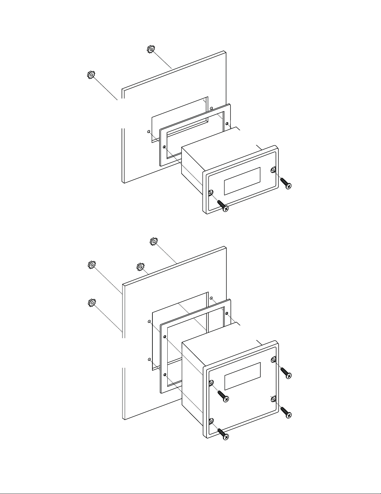
Installation and Mechanical Dimensions
Exploded Panel View
CUSTOMER
MOUNTING PANEL
(HOLE CUT-OUT FOR CONTROL
HOUSING APPROXIMATELY
3.622" WIDE BY 1.770" HIGH)
SUPPLIED WITH EACH CONTROL:
1) GASKET
2) (2) 6-32 X 3/4 PANHEAD BLACK OXIDE STAINLESS SCREWS
3) (2) #6 NUT WITH LOCKWASHER
PANEL MOUNTING GASKET
(WITH THE ADHESIVE SIDE OF
GASKET FACING THE CUSTOMER
MOUNTING PANEL)
MD40P
CONTROL
CUSTOMER
MOUNTING PANEL
(HOLE CUT-OUT FOR CONTROL
HOUSING APPROXIMATELY
3.622" WIDE BY 3.622" HIGH)
SUPPLIED WITH EACH CONTROL:
1) GASKET
2) (4) 6-32 X 3/4 PANHEAD BLACK OXIDE STAINLESS SCREWS
3) (4) #6 NUT WITH LOCKWASHER
PANEL MOUNTING GASKET
(WITH THE ADHESIVE SIDE OF
GASKET FACING THE CUSTOMER
MOUNTING PANEL)
MD50P
CONTROL
3
Page 6
Cut-out and Mounting Dimensions
3.622"
3.622"
HOUSING DEPTH
4.625"
HOUSING DEPTH
4.625"
PANEL CUT-OUT
PANEL CUT-OUT
1.770"
MD50P
MD40P
4.000"
4.000"
.140" x 2
.140" x 4
0.885"
3.622"
0.811"
2.000"
5.000"
4.625"
4.179"
1.928"
MD40P and MD50P Dimensions
5.000"
2.289"
4.625"
1.656"
4
Page 7
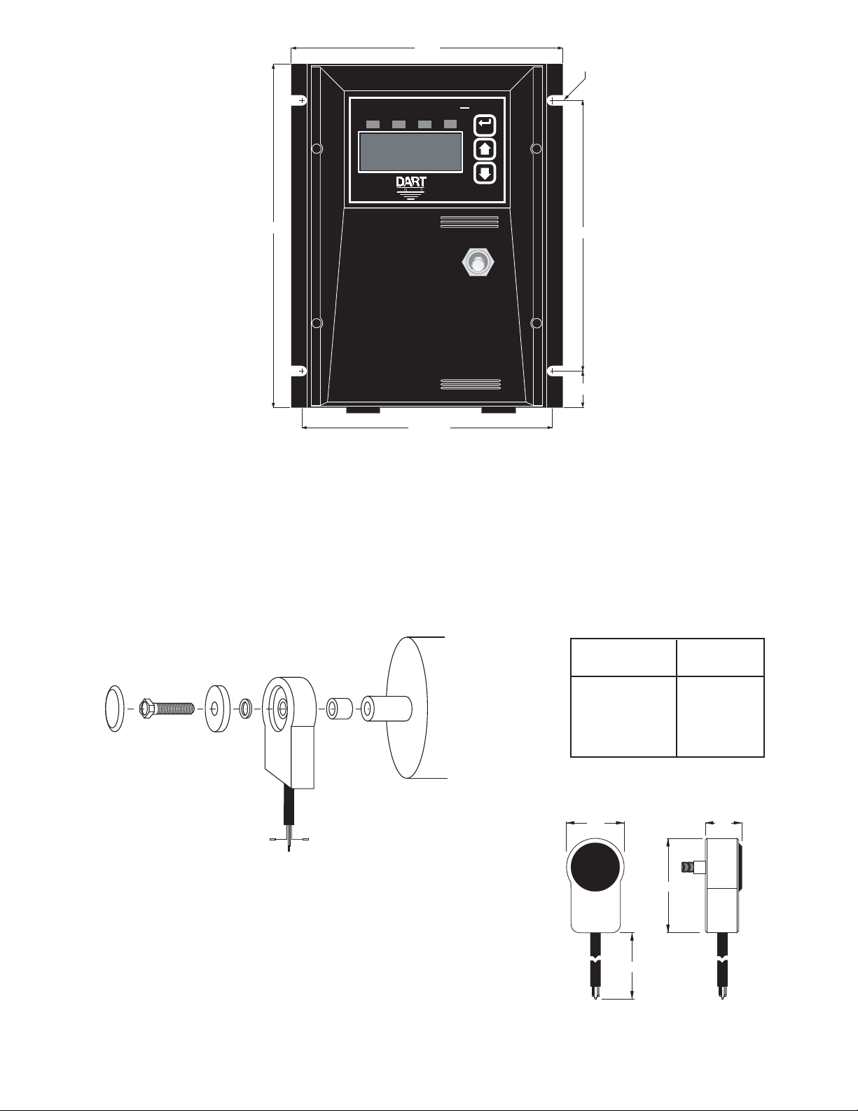
MD50E Mounting and Dimensions
5.530
7/32" TYP.
(4 SLOTS)
.350 DEEP
ValuAuto
Alm2Man
5.125 TYP.
Tach
Error
AUTO
OFF
MAN
---
ENTER
5.500
.750
7.400
Item
Alm1
CONTROLS
PU-E Series Pickup Installation
The PU-E series pickup is an economical way to monitor motor speed. Its patented design provides for
ease of installation in otherwise diffi cult to reach areas. The PU-E operates from a +5V power supply,
producing a 5 volt square wave whose frequency is proportional to speed. This signal is fed into the
MD plus control as a speed or position reference for the microprocessor.
Caution: The PU-E cord should not be grouped with other wires or cords. For applications with PU-E
wire over 6 feet long, or noisy environments, a shielded cable is recommended. Connect the shield
to the common terminal on the MD plus, leaving the shield on the PU-E end fl oating.
dust
cover
10-32
screw
magnet
disc
flat
washer
PU-E
bearing
3/16"
spacer
tapped
motor
shaft
Model
Number
PU-2E
PU-4E
PU-20E
PU-40E
Pulses per
Revolution
1
2
10
20
Dimensions
1.60 .875
2.40
72.00
signal
red wire
+5 volts
black wire
common
white wire
CAUTION:
DO NOT OVER TIGHTEN MOUNTING SCREW !!
No other mounting screws are necessary, as the cord
will keep the unit from rotating.
5
Page 8
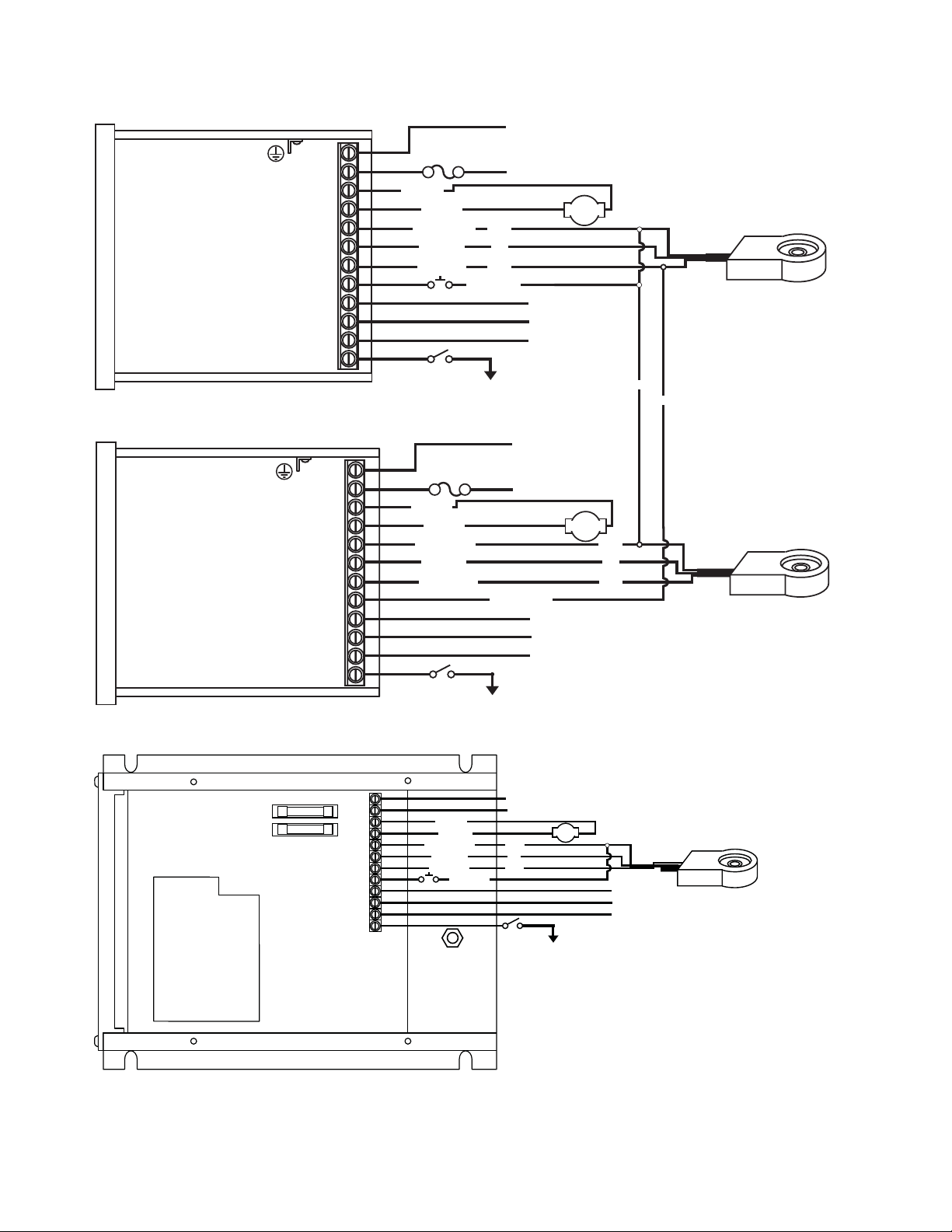
Electrical Installation & Diagrams
P1-12
P1-11
P1-4
P1-5
P1-6
P1-7
P1-8
P1-9
P1-10
P1-3
P1-2
P1-1
PICK-UP MOUNTED
TO MOTOR SHAFT
AC INPUT
AC INPUT
black
white
red
MD50E
MASTER
COMMON
+5VDC
SIGNAL
**INHIBIT
(Mounts on rotating
end shaft with 10-32
tapped hole, 1/2" deep)
}
85-250VAC
}
Form C
Relay Output
(Programmable)
Alarm Output - Normally Open
Alarm Output - Common
Alarm Output - Normally Closed
*
Jog Input
COM (P1-5)
User Input 1
N
L
-A
+A
COM
+5V
S1
S2
NO
C
NC
IN1
-ARM
+ARM
MOTOR
Ground Lug
* For AC inputs utilizing two hot lines, both inputs should be
protected with appropriately sized fuses or circuit breakers.
** P1-8(Master) & P1-12 user input may be programmed
for a number of functions, including (jog, inhibit, etc.)
P1 Terminal Block Hook-Up Diagrams
MD plus
MASTER
MD plus
FOLLOWER
P1-1
P1-2
P1-3
P1-4
P1-5
P1-6
P1-7
P1-8
P1-9
P1-10
P1-11
P1-12
P1-1
P1-2
P1-3
P1-4
P1-5
P1-6
P1-7
P1-8
P1-9
P1-10
P1-11
P1-12
FUSE
MD40P = 7.5 Amp*
N
MD50P = 15 Amp*
L
-A
-ARM
+A
COM
+5V
S1
S2
NO
C
NC
IN1
+ARM
COMMON
+5VDC
SIGNAL
Alarm Output - Normally Open
Alarm Output - Common
Alarm Output - Normally Closed
User Input 1
**INHIBIT
N
L
-A
+A
COM
+5V
S1
S2
NO
C
NC
IN1
FUSE
MD40P = 7.5 Amp*
MD50P = 15 Amp*
-ARM
+ARM
COMMON
+5VDC
SIGNAL 1
Alarm Output - Normally Open
Alarm Output - Common
Alarm Output - Normally Closed
User Input 1
**INHIBIT
black
red
white
**
Jog Input
COM (P1-5)
SIGNAL 2
COM (P1-5)
AC INPUT
AC INPUT
Form C
Relay Output
}
(Programmable)
AC INPUT
AC INPUT
Form C
Relay Output
}
(Programmable)
85-265VAC
}
MOTOR
}
MOTOR
85-265VAC
black
red
white
black
white
PICK-UP MOUNTED
TO MOTOR SHAFT
(Mounts on rotating
end shaft with 10-32
tapped hole, 1/2" deep)
FOLLOWER PICK-UP
MOUNTED TO
MOTOR SHAFT
(Mounts on rotating
end shaft with 10-32
tapped hole, 1/2" deep)
6
Page 9
MD40P / MD50P / MD50E P1 Terminal Block Descriptions
P1-1 (AC / N) – For single phase AC lines connect the Neutral side of the AC line to this terminal.
For systems with two hot AC lines, connect either of the Hot AC lines to this terminal.
P1-2 (AC / L) – For single phase AC lines connect the Hot side of the AC line to this terminal. For
systems with two hot AC lines, connect either of the Hot AC lines to this terminal.
P1-3 (-A) - This is the -Armature terminal. For normal rotation of the motor, the -Armature lead of the
motor should be connected to this terminal. The +Armature lead of the motor will be connected
here when a reverse directional rotation of the armature is desired.
P1-4 (+A) - This is the +Armature terminal. For normal rotation of the motor, the +Armature lead
of the motor should be connected to this terminal. The -Armature lead of the motor will be
connected here when a reverse directional rotation of the armature is desired.
P1-5 (COM) – This is the common point for the control logic. The speed sensor common lead as
well as any other source needing to reference the control common will be connected to this
terminal.
P1-6 (+5V) – This is a self-contained +5VDC power supply capable of up to 50mA. The speed sensor
supply lead can be connected to this terminal for its power source.
P1-7 (S1) – This is the signal input terminal for the motor's digital pickup or encoder. This signal is
internally "pulled-up" to +5VDC via a 2.2K ohm resistor.
P1-8 (S2) – This input can be programmed to perform a number of advanced functions. In Follower
Mode, this input is the signal input terminal for the master's digital pickup or encoder. In Master
modes (Rate and Time), this input can be confi gured to function as an emergency stop, inhibit,
or jog command. This signal is internally "pulled-up" to +5VDC via a 2.2K ohm resistor.
P1-9 (NO) – This is the normally-open contact of the user assignable relay output.
P1-10 (C) – This is the common contact of the user assignable relay.
P1-11 (NC) – This is the normally-closed contact of the user assignable relay output.
P1-12 (IN1) – This input can be programmed to perform a number of advanced functions. It can be
confi gured to function as an emergency stop, inhibit, or jog command. This signal is internally
"pulled-up" to +5VDC via a 2.2K ohm resistor.
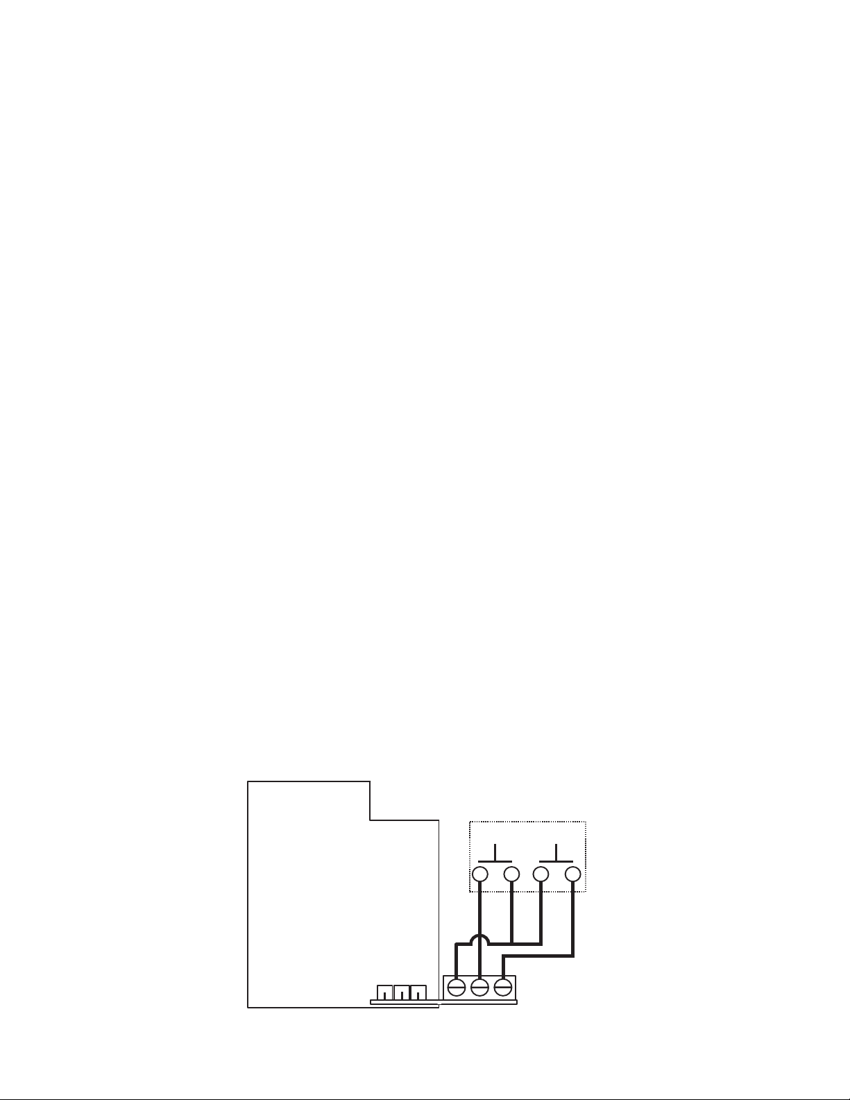
-1 Option Wiring
The -1 option board is a module which allows external up and down push buttons to be wired to the
unit. These buttons operate exactly like the Up and Down buttons on the user interface. This module
is commonly used to allow PLCs or hand-held pendants to operate the front-panel remotely. The wiring
for the external buttons is attached via a 3mm European terminal block on the -1 option board. The
buttons are activated by shorting the terminal labeled Com to either the Up or Down terminal.
REMOTE SWITCHING
MICROPROCESSOR
SERIES PC BOARD
DOWN UP
-1 OPTION
BOARD
COMMON
-3
-2
DOWN
-1
UP
7
Page 10
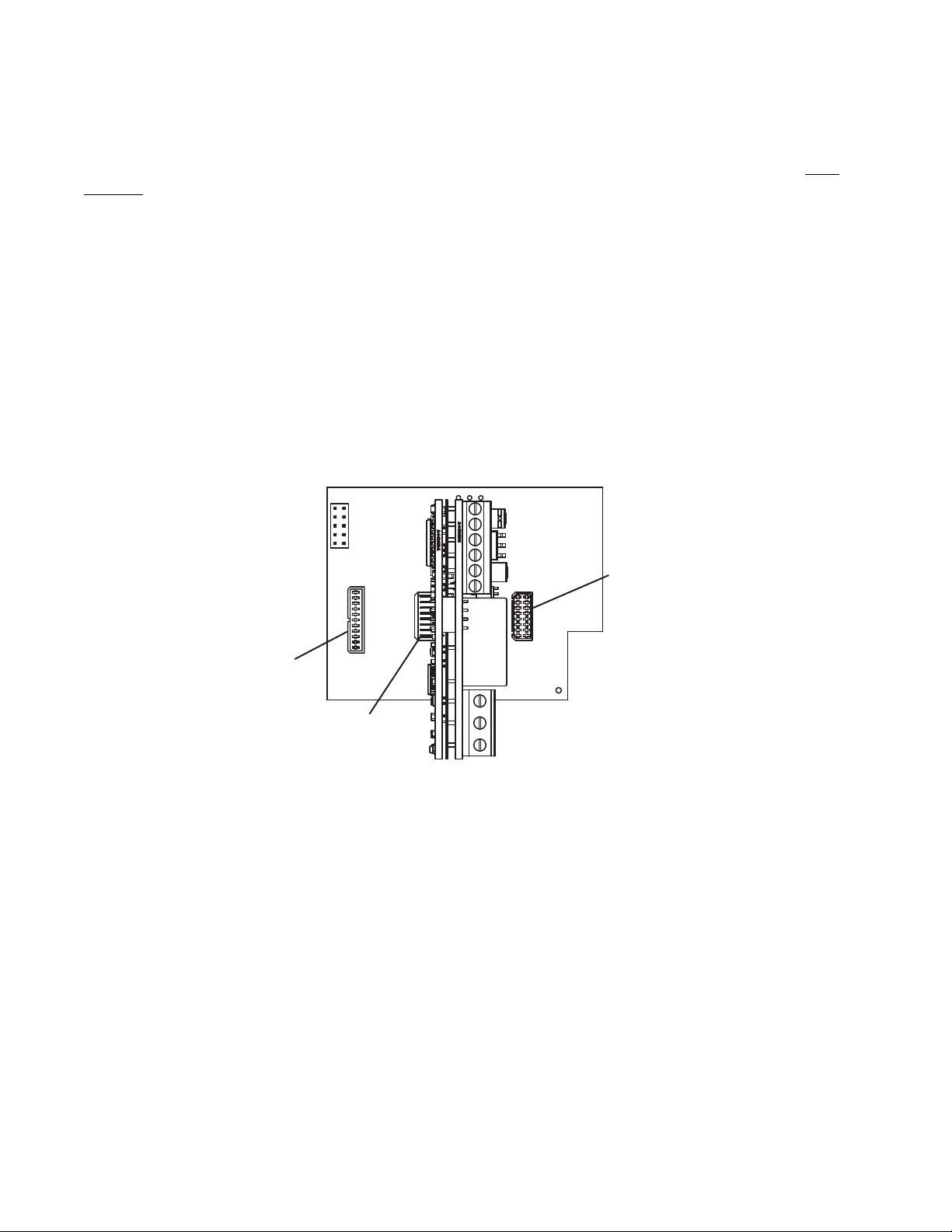
OPT420 Installation & Diagrams
Installing the OPT420 in Slot 200 (ONLY!) of the Host Drive
The OPT420 is a Dart ModularBus "option card" featuring an Optically-Isolated 4-20mA Current Loop
Input and an Optically-Isolated 4-20mA Current Loop Output. Both the input and output are OpticallyIsolated from the Host Drive, circuit common, earth ground, and from each other. In addition, a nonisolated SPST switch input is provided. In the typical application with an MD40/50-420, that switch is
used to determine where the Host Drive gets its "Target Speed" setting from. Additionally, the MD40P420, MD50P-420 and MD50E-420 have an "Auto/Manual" LED Annunciator which displays whether
the source of the Target Setting comes from the 4-20mA input ("Auto") or from the "front panel" Target
setting ("Manual").
In "Manual Mode", the Host Drive uses its normal Front Panel display and Up/Down buttons to set
the Target Speed (or Time). However, in "Auto Mode", the Host Drive follows the OPT420's 4-20mA
Current Loop signal. In either mode, the OPT420's Current Loop Output provides a real-time updating
4-20mA signal that represents the Host Drive motor's Actual (Tach) Speed. This is primarily used by
a SCADA system to provide "feedback" that the SCADA's speed setting was received and acted upon
by the Host Drive.
OPT 420 INSTALLATION
SLOT 100
SLOT 500
SLOT 200
IMPORTANT: THE OPT420 MAY ONLY BE INSTALLED IN MODULARBUS SLOT "200". Installing
in any other slot will simply result in the OPT420 "not working". Normal operation will resume when
the OPT420 is placed in the Host Drive's ModularBus Slot "200".
Also, the OPT420 comes with Default Values that should allow a simple checkout procedure to verify
that everything is hooked-up correctly and functioning. See the OPT420 Item (Parameter) Table for
further details.
(Install OPT420 in slot 200 only)
OPT420 P3 & P6 Terminal Block Hook-Up Diagrams
IMPORTANT: THE OPT420 DOES NOT SUPPLY LOOP "EXCITATION VOLTAGE". If the fl owmeter,
SCADA system, etc. does not have a Loop Excitation supply, an external voltage must be provided
from +9 to +36VDC capable of at least 50mA for each of the two 4-20mA Current Loops (Input and
Output), as shown in the diagram below. Additionally, if the Input and Output must be isolated from
each other, two excitation supplies may be needed.
8
Page 11
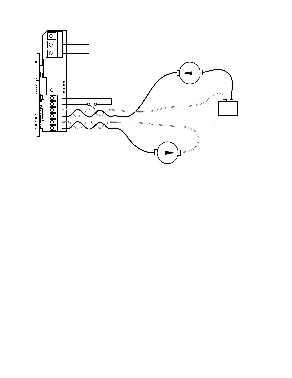
OPT 420 HOOK-UP DIAGRAM (TYPICAL)
P6
3
2
1
6
5
+
4
-
3
+
2
-
1
P3
OPT420 RELAY Output - Common
OPT420 RELAY Output - Normally Open
OPT420 RELAY Output - Normally Closed
- 4-20mA Out
(Black)
Auto / Manual
Switch
(Open = Manual)
- 4-20mA In
(Black)
4-20mA IN
(White)
-
Form C
Relay Output
(Programmable)
}
+
4-20mA OUT
(White)
+
-
+
-
9-36VDC
EXCITATION
SUPPLY
CUSTOMER
SUPPLIED
IF NEEDED
OPT420 P3 Terminal Block Descriptions
P3-1 (- 4-20mA Input) – Connect this terminal to the next 4-20mA device in the loop, or, if the OPT420
is the last device in the current loop, then connect this terminal to the - (negative) side of the
current loop.
P3-2 (+ 4-20mA Input) –Connect this terminal to the previous 4-20mA device in the loop, or, if the
OPT420 is the fi rst device in the current loop, then connect this terminal to the + (positive)
side of the current loop.
P3-3 (- 4-20mA Output) – Connect this terminal to the next 4-20mA device in the loop, or, if the
OPT420 is the last device in the current loop, then connect this terminal to the - (negative)
side of the current loop.
P3-4 (+ 4-20mA Output) –Connect this terminal to the previous 4-20mA device in the loop, or, if the
OPT420 is the fi rst device in the current loop, then connect this terminal to the + (positive)
side of the current loop.
P3-5 (S1 Input) – Connect this terminal to one side of a SPST switch to control Auto/Manual Operation.
If switch is OPEN (or unconnected), MD40/50-420 Target Speed will come from its Target Speed
setting (as usual), if the switch is CLOSED, MD40/50-420 Target Speed will follow the OPT420
4-20mA Current Loop Input. This signal is internally "pulled-up" via a 15K ohm resistor.
P3-6 (COM) – This is the common point for the control logic. Normally, the other side of the SPST
Auto/Manual switch would be connected to this terminal. Note that this means that the Auto/
Manual switch is NOT "isolated".
OPT420 P6 Terminal Block Descriptions
P6-1 (NC) – This is the normally-closed contact of the user-assignable OPT420 Alarm 1 relay.
P6-2 (NO) – This is the normally-open contact of the user-assignable OPT420 Alarm 1relay.
P6-3 (C) – This is the common contact of the user-assignable OPT420 Alarm 1 relay.
9
Page 12

Basic Operating Instructions
Control Algorithm Discussion and P-I-D Tuning
A true P-I-D speed control algorithm is employed in the MD40P-420, MD50P-420 and MD50E-420
which allows precise and quick response to set speed or load changes. The three items, 26, 27 and
28 (Proportional, Integral, Derivative, respectively) are adjustable as shown on page 16. P-I-D can be
tuned to get precise speed response and regulation.
When adjusting P-I-D, begin by using the factory defaults the control is preset to: P (Item 26) to 2300,
I (Item 27) to 1000, D (Item 28) to 0. If further adjustment of P-I-D is needed, follow the steps below.
To adjust P: (Item 26)
Run the motor from zero speed to the set speed. If the start up response of the motor is too slow,
increase “P” in increments of 20 until the desired start up response time is obtained. If the start up
response time is too fast, decrease “P” in increments of 10 until the desired response is reached. “P”
is used to adjust the start up response time only. The start up response time is approximately 0 to
60% of the set speed. “I” can be used if adjustment of the upper response time (60 to 100% of the
set speed) is needed.
To adjust I: (Item 27)
Run the motor from zero speed to the set speed. If the upper response time (60 to 100% of the set
speed) has any hesitation or has too slow of a response, then increase “I” in increments of 5 until the
hesitation is eliminated and/or the desired upper response time is obtained. If the upper response time
is too fast or has too much overshoot, decrease “I” in increments of 3 until the overshoot is eliminated
and/or the desired upper response time is reached.
To adjust D: (Item 28)
“D” can be used to dampen the effect of “P”. By making “D” too large, the response time of the control
can be reduced, so keep “D” as small as possible on non-regenerative controls.
Note: The proportion of P-I-D seems to be more critical than the individual values, i.e.. values of 5050-50 will achieve virtually the same results as 999-999-999.
Master (Rate and Time) and Follower (Ratio) Modes Explained
The MD plus controls have two basic modes of operation, master and follower. In the Master modes,
the controls are capable of operating independently; whereas, in the Follower Mode, the control requires
a signal from a master to operate. The Follower Mode is used in applications which require the MD
plus to closely follow a master process. For example, if a factory has ten conveyors which must be
synchronized over long periods of time, an industrial engineer could use one MD plus as a master
control for the fi rst conveyor and nine MD pluses as slaves or followers which would receive their speed
commands from the fi rst conveyor's master control or pickup.
In Master Rate Mode, the MD plus controls the rate of the motor by tracking the motor's pickup pulses
which are applied to signal input 1 (S1). In this mode, the display indicates in rate units such as
Gallons-per-minute, feet-per-second, or RPM.
In Master Time Mode, the MD plus controls the process time by tracking the motor's pickup pulses which
are applied to signal input 1 (S1). In this mode, the display indicates in time units such as HH:MM or
MM:SS, where HH is hours, MM is minutes, and SS is seconds. This mode is most-commonly used
in time-sensitive processes such as conveyor ovens and plating applications.
In Follower Mode, the MD plus tracks the rate of the pulses which are applied to the master signal
input (S2). From these pulses, it calculates the speed of the master process in RPMs. This rate is
then multiplied by the percentage which is displayed on the user interface. The display is in 0.1% of
master units. For example, 675 = 67.5 percent of master speed. A master running at 1350 RPM, would
cause the follower to run its motor at 67.5% * 1350 RPM or 911.25 RPM. Typical follower applications
include synchronized rotation, synchronized conveyors, and some web-material processes.
10
Page 13
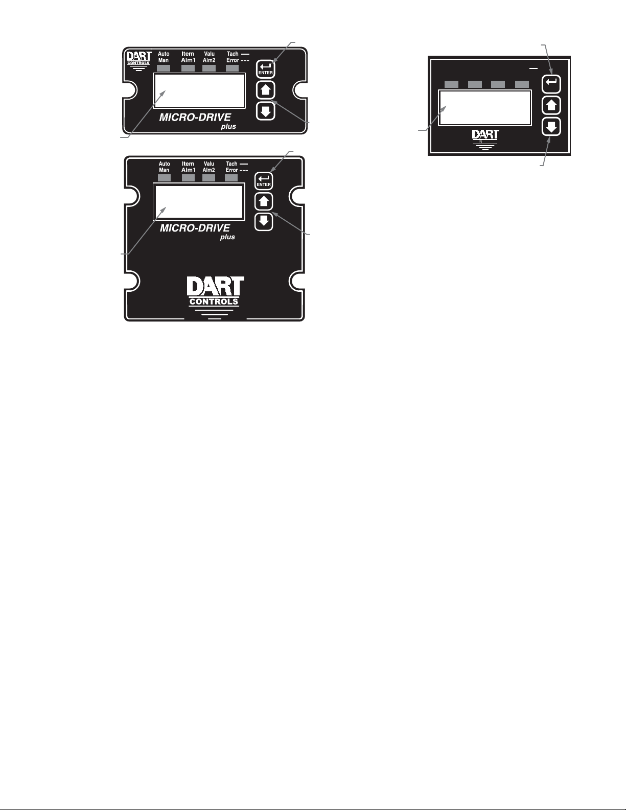
Visual Reference
CONTROLS
ENTER
Tach
Item
ValuAuto
Alm1
Alm2Man
Error
---
Display Window
Up & Down Buttons
ENTER (Select) Button
Up & Down Buttons
ENTER (Select) Button
Display Window
Up & Down Buttons
ENTER (Select) Button
Display Window
How to Change an Item's Value (The Short Story)
1. Hold down the Enter button until Item-Selection Mode is entered. The 'Item' Annunciator will light
2. Using the Up and Down buttons, select the desired Item number to view or edit
3. Press the Enter button to change the value of the Item. The 'Valu' Annunciator will light
4. Using the Up and Down buttons, change the Item's value as desired
5. Press the Enter button to permanently save the changes (Returns to Item-Selection Mode)
6. Select Item Zero ("0") and press the Enter button to return to Running Mode
Operating the User Interface (The Long Story)
Although the MD plus user interface is very versatile, it is also simple to setup and operate. With just a
few button presses, it allows the user to confi gure a number of adjustable Items. The LED display has
three basic operating modes: Running Mode, Item-Selection Mode, and Value Mode. "Item" and "Value"
modes also have specifi c visual indicators (LED "Annunciators") that allow the user to immediately
determine the current state or mode of the user interface. Note: Item-Selection Mode (and Value
Mode) can only be entered if the Program Enable jumper is in the “On” position.
Running Mode is the default display of the unit when power is applied. The MD plus will spend the
majority of its time in this mode. In Running Mode, the display shows the Target or Actual ("Tach") speed
value in the user-defi ned Engineering Units format for rate, time, or (in "Follower" mode) percentage of
Master. The control will continuously attempt to drive the motor to the requested Target. In this display
mode, the Up and Down buttons increase or decrease the displayed target value until either the display
minimum or display maximum limit is reached. Depending on the alarm confi guration, these buttons
may also serve as an alarm-silence or alarm-reset button. For example, displays for rate, time, and
follower operating modes could be 13.60, 45:30, and 1000, respectively.
Additionally, the MD40P-420, MD50P-420 and MD50E-420 have an "Auto/Manual" Annunciator which
displays a "solid" light if the source of the Target Setting comes from the 4-20mA input ("Auto"), or a
"blinking" light if the Target Setting comes from the "front panel" Target setting ("Manual").
11
Page 14

Item-Selection Mode can be entered by simply pressing and holding the Enter button down for about
three seconds. Once in Item-Selection Mode, the "Item" Annunciator will illuminate. The display will
indicate the currently selected Item number for editing purposes. Pressing the Up or Down button
will increase or decrease the selected Item number on the display. Although the Item numbers are in
numerical order, some numbers are skipped. These numbers represent reserved Items that are not
yet implemented and are not displayed.
Further, Item numbers above 999 are actually located on the ModularBus card(s) that are installed
in the "Host" Drive. The numbering scheme is the ModularBus "slot number (100, 200 or 500) times
10, plus the Item Number. Once the desired Item number is displayed, a press of the Enter button will
change the display to the Value Mode. So, for example, to view/edit Item 20 on a ModularBus card in
Slot 200, "Browse" to Item number 2020 (200 X 10 + 20).
When in Item-Selection Mode, pressing the Enter button with Item 0 selected will cause the unit
to return to Running Mode. See the Software Items for a list of available Items.
Value Mode is used to modify the value of the selected Item. When in Value Mode, the "Valu"
Annunciator will illuminate. Pressing the Up or Down button increases or decreases the selected
Item’s value. With only one exception, value changes take effect immediately. For example, when
adjusting P-I-D settings, the change in response can be observed "live", which greatly facilitates the
P-I-D "tuning" process. Once the desired value is showing in the display window, pressing the Enter
button again will return to Item-Selection Mode and the new value will be saved in permanent memory.
Removing power from the unit while in Value Mode will result in the specifi ed new value being lost,
and the previous (old) value being used. This can be used as an "undo", for example, during editing
a value that is being edited in the wrong Item. Note: Changes to Item 10, Operating Mode, do not
take effect until power is removed and re-applied to the MD plus.
Detailed Confi guration Instructions
MD plus Default Confi guration
When shipped from the factory, the following basic settings are in place:
Rate Mode Operation in RPM
S1 and S2 Signal Input Pulses per Revolution: 20 (to use a PU-40E)
Decimal Point Display: None
Display Range: 0 - 2400
Speed Range: 0 - 2400 RPM
Accel and Decel: 9999 RPM per second
Signal Input 2 (S2) Mode: Jog @ 1000 RPM when Low
User Input 1 (UIN1) Mode: Emergency Stop when Low
Alarm 1 and Alarm 2 Outputs: Disabled
Resetting the MD plus to Factory Defaults
The factory-default settings can be easily restored using either of two methods. Both methods require
the Program Enable jumper to be in the “On” position. The fi rst is to apply power to the unit with both the
Enter and Down buttons pressed for 3 seconds. The second is to change the value of Item 95 to 5.
JP1 (Program Enable Jumper)
The JP1 jumper is located under the dust cover on the back end of the upper board. When the jumper
is set to the "Off" position, all programming features are "locked out" from the front panel user. When
the jumper is in the "On" position, the programming Items are open to change. JP1 is shipped from
the factory set in the "On" position.
12
Page 15

Setting and Reading "SoftSwitches"
Like many other devices, the MD
off" options, depending upon the application. Traditionally, this sort of option-selecting was done with
some sort of physical switch or switches (such as a "DIP switch'), or by other means, such as the
"jumper block" used to enable/disable Programming on the MD
this approach to option-selection: 1) Both DIP switches and "jumper blocks" are physically large, and
most require that the device be at least partially disassembled to gain access to them; 2) On a device
with more than just a very few options, the number and combinations of switches quickly becomes
overwhelming.
Because of these drawbacks, the MD
SoftSwitches.
It is easiest to think of an Item containing SoftSwitches as a DIP switch containing from one to thirty-two
switches. But instead of actually fl ipping a switch "on" or "off", you can set and read these "switches"
as a
Binary-Coded-Decimal
computers!", let's look at this another way. Each "switch", from #1 through #32, has been assigned a
decimal number that represents its position in the make-believe DIP switch assembly. When that number
is used, it means that the switch is "on". For example, the decimal number that represents switch #4
is 8, the number that represents switch #6 is 32, and so on. See the table below for a full explanation
of these values. Note: Due to display limitations, switches 15 through 32 are currently unused.
Switch# BCD Value
, or
plus
"BCD"
has the ability to select between a number of "yes/no" or "on/
plus
. There are two problems with
plus
takes a different approach (where appropriate):
number. Now, before you say "Binary numbers! Those are for
Switch# BCD Value
1 1
2 2
3 4
4 8
5 16
6 32
7 64
So, the Binary-Coded-Decimal (BCD) number contained in a SoftSwitch Item is nothing more
than the
switches #1, #4, and #7 to the "on" position, you would place the number 73 (1 + 8 + 64) into the Item
containing those SoftSwitches; if you wanted to set switches #5 and #6 "on", you would place the number
48
(16 + 32) into the Item, and so forth. Simply "add-up" the BCD values of the switches you wish
to "turn on", and place the total, or "sum", into the Item containing the SoftSwitches.
The settings of the SoftSwitches can also be read the same way: For example, if an Item containing
the SoftSwitches has been set to the number
You can tell this by
that is less than or equal to the "total". Keep subtracting, but if you get a negative number as a result,
then don't subtract that BCD value (add it back in before proceeding). Work your way "downward" in
this manner toward Switch #1, but when your total reaches zero, you are fi nished.
sum
of the numbers representing the "on" switches. For example, if you wanted to set
11
, you can tell that switches #1, #2 and #4 are "on".
subtracting
the BCD values, from highest to lowest, starting at the highest value
8 128
9 256
10 512
11 1024
12 2048
13 4096
14 8192
Try a few examples of your own, and very soon you will be easily setting and reading SoftSwitches.
13
Page 16

Setting and Reading "Alarm" Conditions
Taking advantage of the "SoftSwitches" feature described above, the MD
"Alarm" outputs, which can be independently set to Activate on any of 16,384 possible combinations
of "conditions" or "events" that could be occuring at any one time. See table below for a list of these
Condition "Flags".
The conditions are logically "OR-ed" together to form the particular Alarm output. If the SoftSwitches for
the "Tach Outside Limits" and the "Pickup Stalled" Conditions for Alarm1 are set to "On", then Alarm1
will be "true" when either one or both of those Conditions are "true". However, for even more fl exibility,
each condition can be combined in a logical "AND" fashion to "override" the Alarm output.
Additionally, each Condition can be "inverted" before being sent to the "AND" function, for even
greater fl exibility. Please note that if a particular Condition is inverted, the corresponding "switch" in
the appropriate "AND" Item (52/72) is inverted as well.
Further, setting any of the "Softswitch" Items in the OR/Invert/AND Alarm Conditions (Items 50-52 and
70-72) to a value of zero effectively removes the effect of their "logic" from the "Circuit". Therefore, even
though the Alarm logic conditions are "cascaded" OR -> Invert -> AND, if, for example, the application
does not need any "AND" conditions, simply set the value of the AND Item (52 and/or 72) to zero, and
the "AND" function will be "jumped around". In that case, however, it would also be best to set the
"Inverter" Item (51 and/or 71) to zero as well.
plus
is equipped with two
Table: BCD Values for Drive Condition “Flags”
BCD
Value
Description
0 (No Flags are currently Active)
1 Accel/Decel Ramp In Progress
2 S1 (Main) Actual Speed (Tach) is Outside Alarm Limits
4 Target Speed is Outside Alarm Limits
8 Target Speed = 0
16 S1 (Main) Pickup is Stalled
32 S2 (Leader) Pickup is Stopped (Valid only in ‘Follower’ Mode)
64 Jog Function is Activated
128 Inhibit Function is Activated
256 E-Stop Function is Activated
512 Drive is at Maximum Output
1024 “Run” Condition
2048 Slot 100 Alarm1 Activated (Valid only if ModularBus card installed in this slot)
4096 Slot 200 Alarm1 Activated (Valid only if ModularBus card installed in this slot)
8192 Slot 500 Alarm1 Activated (Valid only if ModularBus card installed in this slot)
"Alarm" Output Routing
The "output" of Alarm1 is permanently "routed" to drive the Form-C Relay output on the MD
(see Hook-up Diagram, P1-9 through P1-11). The "output" of Alarm2, however, can be Routed (through
the use of Item 81) to any one of the three ModularBus "slots", 100, 200 or 500.
14
plus
itself
Page 17

MD plus Alarm "Logic"
Note: The "circuitry" shown below is actually implemented in software, not hardware, and although it
makes little difference to the fi nal output produced, that fact should be kept in mind.
Also note that the "switches" on the outputs of the "OR gate", the "AND gate", and the "Implied" AND
gate are only under indirect user control. That is, they are set "automatically" by the action of other
settings that are under user control. For example, the "switch" on the output of the "OR gate" is
automatically set to the "uppermost" position (as shown on the drawing, below) when Item 50 (or 70
for Alarm2) is set to zero."
Often there is more than one way to "connect" the signals and "logic" to acheive the desired result. But
determining the proper signal "polarity" to use is often a tricky problem in "logic circuits". Sometimes
it takes a bit of careful planning to arrange "inverted" and "non-inverted" signals properly. Also, keep
in mind that standard logic "tricks", such as the use of "Negative Logic" techniques, can be used to
further expand your options. See the Application Example on page 32 for further details.
Item 50
(70)
Drive Condition Flags
[BCD Values]
[1] Accel/Decel Ramp
[2] Actual Speed Outside Limits
[4] Target Speed Outside Limits
[8] Target Speed = 0
[16] (Main) Pickup Stalled
[32] (Leader) Stopped
[64] Jog
[128] Inhibit
[256] E-Stop
[512] Maximum Output
[1024] Run
[2048] Slot 100 Alarm1
[4096] Slot 200 Alarm1
[8192] Slot 500 Alarm1
OR
Item
51
(71)
Item
52
(72)
Note:
Numbers in parentheses refer to Alarm2
Item
50=0
(70=0)
Item
50=0
(70=0)
“Implied”
AND
“Open” When Items
50, 51, 52=0
(70, 71, 72=0)
Alarm1
(Alarm2)
Items
AND
51,52 = 0
(71,72 = 0)
Items
51,52=0
(71, 72=0)
15
Page 18

Software Parameters (Items)
Item Description Value Range Units Factory
Default
0 Selecting this item exits to “Run” Mode n/a — n/a n/a
Read-Only Items
1 Model Number 45 = MD40P-420, MD50P-420,
MD50E-420
2 Software Version 1 – 9999 — n/a
3 Hardware Version 1 – 9999 — n/a
4 DartNet Version 1-9999 — n/a
5 Serial Number (Major) 0-9999 — n/a
6 Serial Number (Minor) 0-9999 — n/a
8 Drive Condition Flags (See “Flags” Table, pg. 14) BCD n/a
General Setup Items
10 Operating Mode 1 = Rate Mode
2 = Time Mode
3 = Follower Mode
11 Display Brightness 0 – 31 (Dim – Bright) — 20
12 Display Mode 1 = Target Speed Display
2 = S1 Actual Speed Display
3 = S2 (Leader) Speed Display
13 Decimal Point Position 0 = D.P. Disabled [XXXX]
1 = [X.XXX]
2 = [XX.XX]
3 = [XXX.X]
4 = [XXXX.]
14 Keypad Mode 1 = Linear, Constant Rate
2 = Non-Linear, Accelerating Rate
15 Keypad Scroll Delay 0 – 30 (Fast – Slow) — 10
16 Power-up Target Speed 1 = Force Zero Speed
2 = Force Power-up Value
3 = Use Previous Target Speed
17 Power-Up Value 0 – 9999 (Eng. Units) 0
18 Front-Panel DoubleClick Destination 0 = DoubleClick Ignored
1 = Inhibit
2 = EStop
3 = Jog1
4 = Jog 2
19 Output Invert (UNUSED ON MD40/50) 0 = Normal
1 = Inverted
Control Loop Items
20 Display Minimum 0 – 9998 (Eng. Units) 0
21 Display Maximum 1 – 9999 (Eng. Units) 2400
22 Motor Control Method 0 = Gain Tracking Off, Low Speed Mode Off
1 = Gain Tracking On, Low Speed Mode Off
2 = Gain Tracking Off, Low Speed Mode On
3 = Gain Tracking On, Low Speed Mode On
23 Accel Setting 1 – 9999 (Eng. Units) 2500
24 Decel Setting 1 – 9999 (Eng. Units) 2500
26 Proportional Gain 0 – 9999 — 2300
27 Integral Gain 1 – 9999 — 1000
28 Derivative Gain 0 – 9999 — 0
29 Startup Lag Compensation 0 – 5000 — 0
— 45
— 1
— 1
— 0
— 2
— 3
— 0
— 0
— 1
User
Setting
16
Page 19

Software Parameters (Items), cont'd
Item Description Value Range Units Factory
Default
Signal Input #1 Setup Items
30 S1 Display Reference 0 – 9999 (Eng. Units) 2400
31 S1 Reference RPM 0 -9999 RPM 2400
32 S1 Pulses Per Revolution 1 – 9999 PPR 20
33 S1 Initial Stall Timeout 0 – 9999 (0 = Defeat) Sec. 0
34 S1 Running Stall Timeout 0 – 999.9 (0 = Defeat) 1/10 Sec. 0
Signal Input #2 Setup Items
35 S2 Input Configuration 1 = Disabled (Use for Follower
Mode)
2 = E-Stop When S2 High
3 = E-Stop When S2 Low
4 = Inhibit When S2 High
5 = Inhibit When S2 Low
6 = Jog When S2 High
7 = Jog When S2 Low
36 S2 Setpoint for Jog Function 1 – 9999 (Eng. Units) 1000
37 S2 Pulses Per Revolution (Follower Only) 1 – 9999 PPR 20
38 S2 Stopped Timeout (Follower Mode Only) 0 – 999.9 (0 = Defeat) 1/10 Sec. 0
User Input #1 (UIN1) Setup Items
40 UIN1 Input Configuration 1 = Disabled
2 = E-Stop When UIN1 High
3 = E-Stop When UIN1 Low
4 = Inhibit When UIN1 High
5 = Inhibit When UIN1 Low
6 = Jog When UIN1 High
7 = Jog When UIN1 Low
41 UIN1 Setpoint for Jog Function 1 – 9999 (Eng. Units) 1000
42 Inhibit Configuration 0 = No Accel/Decel
1 = Decel Only, No Accel
2 = Accel Only, No Decel
3 = Both Accel and Decel
Alarm Output #1 Setup Items
50 Alarm1 Logical “OR” Activation Conditions (See “Flags” Table, pg. 14) BCD 0
51 Alarm1 Logical Inverters (See “Flags” Table, pg. 14) BCD 0
52 Alarm1 Logical “AND” Activation Conditions (See “Flags” Table, pg. 14) BCD 0
53 Alarm1 Output Style & Reset Mode 1 = Constant & Auto-Reset
2 = Constant & Manual Reset
3 = Pulsed & Auto Reset
4 = Pulsed & Manual Reset
54 Alarm1 Reset Configuration 1 = No Silence, Reset on Enter
But.
2 = No Silence, Reset on S2 High
3 = No Silence, Reset on S2 Low
4 = Silence & Reset on Enter But.
5 = Silence & Reset on S2 High
6 = Silence & Reset on S2 Low
55 Annunciator Alm1 Flash On Active Alarm1 0 = No Annunciator Flash
1 = Annunciator Flash
56 Alarm1 Output Pulse “ON” Time 1 – 3600 Secs. 1
57 Alarm1 Output Pulse “OFF” Time 1 – 3600 Secs. 1
58 Alarm1 Output Pulse Count 0 – 9999 — 0
59 Alarm1 Lower Limit 0 – 9999 (Eng. Units) 0
60 Alarm1 Upper Limit 0 – 9999 (Eng. Units) 9999
— 7 n/a
— 3
— 0
— 1
— 1
— 0
User
Setting
17
Page 20

Software Parameters (Items), cont'd
Item Description Value Range Units Factory
Default
User
Setting
Alarm Output #2 Setup Items
70 Alarm2 Logical “OR” Activation Conditions (See “Flags” Table, pg. 14) BCD 0
71 Alarm2 Logical Inverters (See “Flags” Table, pg. 14) BCD 0
72 Alarm2 Logical “AND” Activation Conditions (See “Flags” Table, pg. 14) BCD 0
73 Alarm2 Output Style & Reset Mode 1 = Constant & Auto-Reset
2 = Constant & Manual Reset
3 = Pulsed & Auto Reset
4 = Pulsed & Manual Reset
74 Alarm2 Reset Configuration 1 = No Silence, Reset on Enter But.
2 = No Silence, Reset on S2 High
3 = No Silence, Reset on S2 Low
4 = Silence & Reset on Enter But.
5 = Silence & Reset on S2 High
6 = Silence & Reset on S2 Low
75 Annunciator Alm2 Flash On Active Alarm2 0 = No Annunciator Flash
— 1
— 1
— 0
1 = Annunciator Flash
76 Alarm2 Output Pulse “ON” Time 1 – 3600 Secs. 1
77 Alarm2 Output Pulse “OFF” Time 1 – 3600 Secs. 1
78 Alarm2 Output Pulse Count 0 – 9999 — 0
79 Alarm2 Lower Limit 0 – 9999 (Eng. Units) (Eng. Units) 0
80 Alarm2 Upper Limit 0 – 9999 (Eng. Units) (Eng. Units) 9999
81 Alarm2 Output Routing 1 = Reserved
— 3
2 = Use Slot 100 Alarm1 Output
3 = Use Slot 200 Alarm1 Output
4 = Use Slot 500 Alarm1 Output
Item Memory Commands (Actions)
95 Restore MD40/50 Settings to Factory
Defaults (affects Drive Settings Only)
96 Restore ModularBus Card(s) Settings to
Factory Defaults (Card(s) Settings Only)
0 = Do Nothing & Exit
5 = Restore Factory Defaults
0 = Do Nothing & Exit
100 = Restore Slot 100 Defaults
— 0 n/a
— 0 n/a
200 = Restore Slot 200 Defaults
500 = Restore Slot 500 Defaults
98 Save “Environment” (Drive and ALL
ModularBus Card(s) Settings) to “User Save”
storage area
99 Restore/Swap “Environment” (Drive and ALL
ModularBus Card(s) Settings) from “User
Save” storage area
0 = Do Nothing & Exit
5 = Copy current
(or Settings1 if currently using
Settings2)
0 = Do Nothing & Exit
5 = Copy
FROM Settings2 (or Settings1 if
currently using Settings2)
10 = Swap
Settings TO Settings2
(Restore) current Settings
Between Settings1 & 2
— 0 n/a
— 0 n/a
18
Page 21

Item (Parameter) Descriptions
Item 0 – Exit to Running Mode
When Item 0 is selected in Item-Selection Mode, the unit will return to Running Mode and, depending
on the value of Item 12, will display the running (Target) or actual (Tach) value. This should be selected
once changes to Items are completed.
Item 1 – Model Number (Read Only)
This number represents the base model number for the product. The model code for the MD40P-420
,MD50P-420, and MD50E-420 is 45. In this manual, where appropriate, the “Drive” portion of these
products are referred to as the “Microdrive plus”, or “MD plus”.
Item 2 – Software Version (Read Only)
The software version is a code which identifi es the software “build number” of the unit.
Item 3 – Hardware Version (Read Only)
The hardware version is a code which identifi es which hardware was used to build the unit.
Item 4 – ModularBus Protocol Version (Read Only)
The ModularBus protocol version is a code which identifi es the highest (most-recent) version of the
ModularBus protocol with which this unit is compatible.
Item 5 & 6 – Serial Number, Major & Minor (Read Only)
These Items are reserved for future use as an electronic serial number and are unique to each
manufactured unit.
Item 8 – Drive Condition Flags (Read Only)
This is a Binary Coded Decimal (“BCD”) representation of the currently active “Flags” representing
certain real-time conditions and/or modes in which the drive is operating. This display is updated several
times per second to refl ect the up-to-the-second status of the drive and its ModularBus cards, if any.
See “Flags” table on page 14 for the BCD values.
Item 10 – Operating Mode
This Item defi nes the operating mode for the entire unit. There are two basic modes of operation, master
and follower. In master modes, the unit controls the load using either rate or time units. In follower
mode, the unit controls the load in percentage of master rate.
NOTE: Power must be removed and re-applied to the MD plus for a change in Operating Mode to take
effect. It is also strongly suggested the Target Speed be reduced to zero and the setting of Items 16,
17, 20, 21, 30 & 31 be reviewed carefully prior to doing so.
The following Operating Modes are available for the MD plus:
Mode 1 – Master, Rate Mode
In Rate Mode, the MD plus displays in user-defi ned rate "Engineering Units" such as RPM, Gallons
per Hour, or Feet per Second.
Mode 2 – Master, Time Mode
In Time Mode, the MD plus displays in time units using the format AA:BB. By default AA:BB
represents minutes (AA) and seconds (BB). Optionally, it can be confi gured to represent hours
(AA) and minutes (BB) or other user-defi ned units with a 1:60 relationship. When setting Items
which are confi gured in engineering units, the programmed value is the determined by the formula
(AA * 60) + BB. In HH:MM displays, this is the total number of minutes. In MM:SS displays, this
is the total number of seconds.
Mode 3 – Follower Mode
In Follower Mode, the MD plus displays in percentage units, where 1000 equals 100.0 percent of
the master rate. For example, if the display indicates 985, 98.5, or 9.85, the MD plus will attempt
to run at exactly 98.5 percent of the master rate. Display settings are always entered ignoring the
decimal point’s position.
19
Page 22

Item 11 – Display Intensity
This Item adjusts the intensity of the LED display digits in the front panel of the unit. The values of
0 – 31 correspond to a gradual change from very dim to very bright. This is often useful when the MD
plus is used in the same panel as other pieces of equipment with LED displays and a uniform display
brightness is desired. Simply adjust the MD plus to match its surroundings.
Item 12 – Display Mode
This Item selects what the MD plus will show on its display during Run Mode. Note that it can “toggle”
between whatever the Display Mode is set to and its “opposite” by briefl y pressing and releasing the
ENTER button. For example, if this Item is set to 1 (Target Speed/Time), pressing the ENTER button
will briefl y show the Actual (Tach) Display (and illuminate the “Tach” LED Annunciator). Conversely,
if this Item is set to 2 or 3 (Main Tach or Leader Tach, respectively), pressing the ENTER button will
briefl y show the Target Speed/Time.
The following Display Modes are available for the MD plus:
Mode 1 – Target Speed/Time Display
In Rate Mode, the MD plus displays the Target Speed in user-defi ned rate Engineering Units such
as RPM, Gallons per Hour, or Feet per Second. In Time Mode, the MD plus displays the Target Time
in time units using the format AA:BB. In Follower Mode, the MD plus displays the Target Speed in
percentage units, where 1000 equals 100.0 percent of the Master rate.
Mode 2 – S1 (Main Pickup) Actual Speed (Tach) Display
In Rate Mode, the MD plus displays the Actual Speed in user-defi ned rate Engineering Units such
as RPM, Gallons per Hour, or Feet per Second. In Time Mode, the MD plus displays the Actual Time
in time units using the format AA:BB. In Follower Mode, the MD plus displays the Actual Speed in
percentage units, where 1000 equals 100.0 percent of the Master rate.
Mode 3 – S2 (Leader) Actual Speed (Tach) Display
Mainly useful for diagnosing and setup of Master-Follower applications, selecting this Mode shows
the Leader Speed (on the S2 Input) in RPM Units (only).
Item 13 – Decimal Point (DP) Position (used in Rate and Follower Modes Only)
This selects the format of the display with respect to the decimal point’s position. This Item does not
effect the value entry for other Items. For example, if the user desires to display 10.00 at 300RPM,
then Item 30 would be set to 1000, Item 31 would be set to 300, and Item 13 would be set to 2.
Mode 0: Fixed XXXX
Mode 1: Fixed X.XXX
Mode 2: Fixed XX.XX
Mode 3: Fixed XXX.X
Mode 4: Fixed XXXX.
Item 14 – Keypad Mode
This Item selects the operating mode of the front-panel push buttons. In some applications, increasing
or decreasing the scroll rate provides the user more controllability when entering settings. Items 14 and
15 affect only the Up and Down buttons when the user interface is in Running Mode. These settings
also apply to remote Up / Down buttons which are attached via the -1 option board.
Mode 1: Linear, Constant Rate
In linear mode, pressing and holding the Up or Down buttons will cause the display to continuously
change value in the requested direction until either the Display Minimum or Display Maximum is
reached. The displayed value will scroll at a constant rate which is specifi ed using Item 15.
Mode 2: Non-linear, Accelerating Rate
In non-linear mode, pressing and holding the Up or Down buttons will cause the display to
continuously change value in the requested direction until either the Display Minimum or Display
Maximum is reached. The displayed value will initially scroll at a slow rate and increase in speed
until the maximum scroll rate is achieved. The initial scroll rate is specifi ed using Item 15.
20
Page 23

Item 15 – Keypad Scroll Delay
This Item sets the scroll speed for the front-panel push buttons. The function of this Item varies slightly
depending on the Keypad Mode. See Item 14 for more details.
Item 16 – Power-up Target Speed
This Item determines the default Running Value when power is initially applied to the MD plus.
Mode 1: Default to Zero
When in this mode, the unit will default to zero (engineering units).
Mode 2: Default to Power-Up Value
When in this mode, the unit will default to the Power-up Value, Item 17.
Mode 3: Default to Previously Running Value
When in this mode, the unit will default to the previous running value before power was removed.
A previous running value must have been active for at least 3 seconds to be recalled after power
has been disconnected and reapplied.
Item 17 – Power-up Value
When Power-up Mode is set to 2, this Item will designate the default display value at power-up in the
user’s desired units of measure (“engineering units”), e.g. RPM, GPM, FPM, etc.
Item 18 – Front Panel DoubleClick Routing
This Item determines what happens if the user "Double-Clicks" the Enter Button (two button presses
quickly) on the front panel of the MD plus.
Mode 0: DoubleClick Ignored
When in this mode, DoubleClicking on the Enter Button will have no effect.
Mode 1: Route DoubleClick to Inhibit
When in this mode, Double-Clicking on the Enter Button with the drive is "running" will place the
Drive in Inhibit, obeying the "acel/decel rules" found in Item 42. Additionally, if the S2 and/or UIN1
inputs are set up to provide Inhibit control, they are active as well, with the following rules. Either
the DoubleClick and/or S2/UIN1 can cause the control to go into Inhibit, but both the DoubleClick
AND S2/UIN1 have to be "negated" (set to allow the control to "run") before the control will exit
"Inhibit" mode and begin to "run" normally again. Note that the DoubleClick action works as
a "toggle", so the operation could be somewhat confusing if S2/UIN1 are "routed" to the Inhibit,
along with the DoubleClick, but this behavior is necessary for "safety" reasons.
Mode 2: Route DoubleClick to EStop
Same as Mode 1, but DoubleClick is Routed to the E-Stop function.
Mode 3: Route DoubleClick to Jog1
Same as Mode 1, but DoubleClick is Routed to the Jog1 function, causing the control to temporarily
run at the Target Speed in Item 36. See, also, Item 36.
Mode 4: Route DoubleClick to Jog2
Same as Mode 1, but DoubleClick is Routed to the Jog2 function, causing the control to temporarily
run at the Target Speed in Item 41. See, also, Item 41.
Item 19 – Reserved
Item 20 – Display Minimum
This Item defi nes the lower end of the display range. This is the value which limits how low the user
is able to scroll the displayed value in Running Mode. In Rate and Time modes, this value is set in
engineering units. In Follower Mode, this is set in percentage (actually, 10ths of percentage) of the
master rate. For example, in Follower Mode, a Target of 150 represents 15.0 percent of the master
rate.
Item 21 – Display Maximum
This Item defi nes the upper end of the display range. This is the value which limits how high the user
is able to scroll the displayed value in Running Mode. In Rate and Time modes, this value is set in
engineering units. In Follower Mode, this is set in percentage (actually, 10ths of percentage) of the
master rate. For example, in Follower Mode, a Target of 1250 represents 125.0 percent of the master
rate.
21
Page 24

Item 22 – Motor Control Method
This Item controls two behaviors in the MD plus, Low-Speed "Gain-Tracking", and Ultra-Low-Speed Control
Mode ("gearbox" mode). When set to a value of 1 (or 3), this item automatically (and proportionally)
reduces the "gain" of the PID values when the Target Speed (in RPMs) is less than 200. This greatly
increases the overall stability at low speeds in applications that require a very wide range of Target
Speeds, without having to unduly compromise control responsiveness at higher speeds. When set to
a value of 2 (or 3), this Item adjusts the speed-control characteristics of the MD plus to enhance the
smoothness of speed control when in a situation where the “tach pickup” must be installed on the “low
speed side” of a very slowly turning gear-motor output shaft. A rule of thumb would probably be that
you may consider enabling this Mode if that shaft is turning less than 10 RPM, and the pickup produces
less than 10 Pulses Per Revolution (PPR). Use this Mode only if speed stability can not be achieved
by adjusting the PID settings (Items 26 – 28).
Mode 0: Disabled
Both Low-Speed-Gain-Tracking and Ultra-Low-Speed Control Mode are Defeated.
Mode 1: Low-Speed-Gain-Tracking (Only) Enabled
Low-Speed-Gain-Tracking is Enabled, Ultra-Low-Speed Control Mode is Defeated.
Mode 2: Ultra-Low-Speed Control Mode (Only) Enabled
Low-Speed-Gain-Tracking is Defeated, Ultra-Low-Speed Control Mode is Enabled.
Mode 3: Low-Speed-Gain-Tracking and Ultra-Low-Speed Control Mode (Both) Enabled
Both Low-Speed-Gain-Tracking and Ultra-Low-Speed Control Mode are Enabled.
Item 23 – Acceleration Setting
This Item determines how fast the MD plus will accelerate toward the displayed target setting. This
Item is set in engineering units of change per second, such as RPM, GPM, or feet per second. In
Follower Mode, this Item is set in RPM units.
Item 24 – Deceleration Setting
This Item determines how fast the MD plus will decelerate toward the displayed target setting. This
Item is set in engineering units of change per second, such as RPM, GPM, or feet per second. In
Follower Mode, this Item is set in RPM units.
Item 26 – Proportional (P) Gain
The Proportional Gain is the fi rst of three Items which defi ne the responsiveness of the control with
respect to how fast it responds to changing loads. Because the MD plus controls are true velocity-form
PID control, the higher the P Gain, the more aggressively the unit will respond to a change in load or
target speed. See the “Basic Operating Instructions” section of the manual for more details.
Item 27 – Integral (I) Gain
The Integral Gain is the second of two Items which defi ne the responsiveness of the control with respect
to how fast it responds to changing loads. The higher the I Gain, the more aggressively the unit will
drive the load. However, it will sometimes be necessary to decrease the I Gain and/or increase the P
Gain to prevent unwanted oscillation and instabilities. See the “Basic Operating Instructions” section
of the manual for more details.
Item 28 – Derivative (D) Gain
The Derivative Gain is the third of the three Items which defi ne the responsiveness of the control with
respect to how fast it responds to changing loads. Although most applications will run fi ne with the D
Gain set to zero, sometimes adding a little “D” will help minimize overshoot and undershoot. See the
“Basic Operating Instructions” section of the manual for more details.
Item 29 – Startup Lag Compensation
Somewhat analogous to a “Min. Speed” control on analog motor speed controls, this sets a “minimum
output” that is applied as soon as the Target Speed is above Zero RPM. Careful use of this setting
can help with “stiction” (the tendency for motors to require a bit more “oomph” to “break free” when
starting from a dead stop). However, values that are too high will make the motor “creep” or even be
unable to attain a desired target speed. In Follower Mode, this setting can also help the Follower start
up in better “sync” with the Leader.
22
Page 25

Item 30 – Signal Input 1 (S1) (Main Pickup) Display Reference
This is the number to be displayed when at the user-specifi ed motor Reference RPM. In Rate
Mode, this value represents rate units such as feet, ounces, or revolutions. In Time Mode, this value
represents the reference time measured in seconds or minutes. If the desired display is HH:MM, then
all values should be entered in minutes. If MM:SS is desired, then all values should be entered in
seconds. In Follower Mode, this value is the percentage of the master rate in 0.1% units. For example,
1000 equates to 100%.
Item 31 – Signal Input 1 (S1) Reference RPM
This is the reference RPM at which the Display Reference value should be displayed. In Rate and
Time Modes, this value represents the RPM of the encoder to which the Display Reference corresponds.
In Follower Mode, this value is not used.
Item 32 – Signal Input 1 (S1) Pulses per Revolution
This is the number of pulses per revolution for the signal input 1 (S1). The MD plus supports pickups
and encoders from 1 to 9999 pulses per revolution.
Item 33 – Signal Input 1 (S1) Initial Stall Timeout
When the Target Speed is above zero RPM, this Item determines the maximum time in units of seconds
that can elapse before the fi rst S1 pickup pulse before the MD plus considers itself in a “Stall” Condition.
It is not advisable to set this lower than approximately 10 seconds (a value of 10), or it may be diffi cult
to achieve startup in a low-speed application. A value of zero defeats this timeout.
Item 34 – Signal Input 1 (S1) Running Stall Timeout
When the Target Speed is above zero RPM, this Item determines the maximum time in units of 0.1
Seconds that can elapse between S1 pickup pulses before the MD plus considers itself in a “Stall”
Condition. It is not advisable to set this lower than approximately 10 seconds (a value of 100), or it may
be diffi cult to achieve startup in a low-speed application. Also note that the S1 Pulses Per Revolution
(PPR) must be taken into account when determining the proper setting for this timeout. A value of
zero defeats this timeout.
Item 35 – Signal Input 2 (S2) Input Confi guration
This Item determines the operating mode of signal input 2 (S2).
Mode 1: Disabled (Follower Mode)
The S2 input is inactive. This is the required setting for Follower Mode.
Mode 2: Emergency Stop When S2 High (Not Wired To Common)
When the S2 input is at an electrically high (+5V) state or allowed to fl oat disconnected, the MD
plus will enter emergency-stop mode. While in this mode, the armature output will immediately
be turned off. Once the S2 input returns to an electrically low state or wired to the unit’s common,
the output will become active.
Mode 3: Emergency Stop When S2 Low (Wired To Common)
When the S2 input is at an electrically low state or wired to the unit’s common, the MD plus will
enter emergency-stop mode. While in this mode, the armature output will immediately be turned
off. Once the S2 input returns to an electrically high (+5V) state or allowed to fl oat disconnected,
the output will become active.
Mode 4: Inhibit When S2 High (Not Wired To Common)
When the S2 input is at an electrically high (+5V) state or allowed to fl oat disconnected, the MD
plus will enter inhibit mode. While inhibited, the armature output will decrease according to the
decel setting until zero output is reached. Once the S2 input returns to an electrically low state or is
wired to the unit’s common, the output will start to accelerate toward the previous running value.
Mode 5: Inhibit When S2 Low (Wired To Common)
When the S2 input is at an electrically low state or wired to the unit’s common, the MD plus will enter
inhibit mode. While inhibited, the armature output will decrease according to the decel setting until
zero output is reached. Once the S2 input returns to an electrically high (+5V) state or allowed to
fl oat disconnected, the output will start to accelerate toward the previous running value.
23
Page 26

Mode 6: (JOG1) Jog When S2 High (Not Wired To Common)
When the S2 input is at an electrically high (+5V) state or allowed to fl oat disconnected, the MD
plus will enter JOG1 mode. While in JOG1 mode, the display will immediately change to the
programmed JOG1 setpoint, Item 36. The unit will start accelerating or decelerating toward the
JOG1 setting at the confi gured accel and decel rates. Once the S2 input returns to an electrically
low state or is wired to the unit’s common, the output will start to accelerate or decelerate toward
the previous running value. In Follower Mode, the unit will operate as its own master. This allows
an application to jog by overriding a stopped master.
Mode 7: (JOG1) Jog When S2 Low (Wired To Common)
When the S2 input is at an electrically low state or wired to the unit’s common, the MD plus will
enter JOG1 mode. While in JOG1 mode, the display will immediately change to the programmed
JOG1 setpoint, Item 36. The unit will start accelerating or decelerating toward the JOG1 setting
at the confi gured accel and decel rates. Once the S2 input returns to an electrically high (+5V)
state or allowed to fl oat disconnected, the output will start to accelerate or decelerate toward the
previous running value. In Follower Mode, the unit will operate as its own master. This allows an
application to jog by overriding a stopped master.
Item 36 – Signal Input 2 (S2) Setpoint for JOG1 Function
When the S2 confi guration, Item 35, is set to one of the JOG1 modes, this Item defi nes the JOG1
setpoint in engineering units. If the MD plus operating mode is set to Follower Mode, then this Item is
set in RPM units. This allows a follower control to be jogged when the master is stopped.
Item 37 – Signal Input 2 (S2) (“Leader”) Pulses per Revolution (for Follower Mode Only)
When in Follower Mode, this is the number of pulses per revolution for the signal input 2 (S2) used as
the “Leader” input. The MD plus supports pickups and encoders from 1 to 9999 pulses per revolution
(PPR).
Item 40 – User Input 1 (UIN1) Confi guration
This Item determines the operating mode of user input 1 (UIN1).
Mode 1: Disabled
The UIN1 input is inactive.
Mode 2: Emergency Stop When UIN1 High (Not Wired To Common)
When the UIN1 input is at an electrically high (+5V) state or allowed to fl oat disconnected, the MD
plus will enter emergency-stop mode. While in this mode, the armature output will immediately be
turned off. Once the UIN1 input returns to an electrically low state or wired to the unit’s common,
the output will become active.
Mode 3: Emergency Stop When UIN1 Low (Wired To Common)
When the UIN1 input is at an electrically low state or wired to the unit’s common, the MD plus will
enter emergency-stop mode. While in this mode, the armature output will immediately be turned
off. Once the UIN1 input returns to an electrically high (+5V) state or allowed to fl oat disconnected,
the output will become active.
Mode 4: Inhibit When UIN1 High (Not Wired To Common)
When the UIN1 input is at an electrically high (+5V) state or allowed to fl oat disconnected, the MD
plus will enter inhibit mode. While inhibited, the armature output will decrease according to the decel
setting until zero output is reached. Once the UIN1 input returns to an electrically low state or is
wired to the unit’s common, the output will start to accelerate toward the previous running value.
Mode 5: Inhibit When UIN1 Low (Wired To Common)
When the UIN1 input is at an electrically low state or wired to the unit’s common, the MD plus will
enter inhibit mode. While inhibited, the armature output will decrease according to the decel setting
until zero output is reached. Once the UIN1 input returns to an electrically high (+5V) state or allowed
to fl oat disconnected, the output will start to accelerate toward the previous running value.
24
Page 27

Mode 6: (JOG2) Jog When UIN1 High (Not Wired To Common)
When the UIN1 input is at an electrically high (+5V) state or allowed to fl oat disconnected, the
MD plus will enter JOG2 mode. While in JOG2 mode, the display will immediately change to the
programmed JOG2 setpoint, Item 41. The unit will start accelerating or decelerating toward the
JOG2 setting at the confi gured accel and decel rates. Once the UIN1 input returns to an electrically
low state or is wired to the unit’s common, the output will start to accelerate or decelerate toward
the previous running value. In Follower Mode, the unit will operate as its own master. This allows
an application to jog by overriding a stopped master.
Mode 7: (JOG2) Jog When UIN1 Low (Wired To Common)
When the UIN1 input is at an electrically low state or wired to the unit’s common, the MD plus will
enter JOG2 mode. While in JOG2 mode, the display will immediately change to the programmed
JOG2 setpoint, Item 41. The unit will start accelerating or decelerating toward the JOG2 setting
at the confi gured accel and decel rates. Once the UIN1 input returns to an electrically high (+5V)
state or allowed to fl oat disconnected, the output will start to accelerate or decelerate toward the
previous running value. In Follower Mode, the unit will operate as its own master. This allows an
application to jog by overriding a stopped master.
Item 41 – User Input 1 (UIN1) Setpoint for JOG2 Function
When the UIN1 confi guration, Item 40, is set to one of the JOG2 modes, this Item defi nes the JOG2
setpoint in engineering units. If the MD plus operating mode is set to Follower Mode, then this Item is
set in RPM units. This allows a follower control to be jogged when the master is stopped.
Item 42 – Inhibit Confi guration
This Item determines the accel/decel profi le of the MD plus when it is going into and out of “Inhibit”
Mode. There are 4 possible settings:
Mode 0: No Accel/Decel
When going into Inhibit, the MD plus will immediately shut off its output, disregarding any Decel
setting, and when coming out of Inhibit, the MD plus will immediately return to its Target Speed,
disregarding any Accel setting. This is exactly like the “E-Stop” behavior.
Mode 1: Decel Only, No Accel
When going into Inhibit, the MD plus will Decel to a stop using the setting in Item 24, but when
coming out of Inhibit, the MD plus will immediately return to its Target Speed, disregarding any
Accel setting.
Mode 2: Accel Only, No Decel
When going into Inhibit, the MD plus will immediately shut off its output, disregarding any Decel
setting, but when coming out of Inhibit, the MD plus will Accelerate to its Target Speed, using the
Accel setting in Item 23.
Mode 3: Use Both Accel and Decel
When going into Inhibit, the MD plus will Decel to a stop using the setting in Item 24, and when
coming out of Inhibit, the MD plus will Accelerate to its Target Speed, using the Accel setting in
Item 23.
Item 50 – Alarm 1 Logical “OR” Activation Conditions
This Item, in conjunction with Items 51 & 52, defi nes which conditions will result in the Alarm 1 output
being activated. The function is that of a Logical “OR”ing of the selected Drive Condition Flags. A setting
of zero defeats this “OR” function entirely. Please see the sections “Setting and Reading Softswitches”
and “Setting Alarm Conditions” for further details.
Item 51 – Alarm 1 Logical Activation Condition Inverters
This Item, in conjunction with Items 50 & 52, defi nes which conditions will result in the Alarm 1 output
being activated. The function allows selected Drive Condition Flags to be “inverted” before being
presented to the “inputs” of the “AND” function (see Item 52). Please see the sections “Setting and
Reading Softswitches” and “Setting Alarm Conditions” for further details.
25
Page 28

Item 52 – Alarm 1 Logical “AND” Activation Conditions
This Item, in conjunction with Items 50 & 51, defi nes which conditions will result in the Alarm 1 output
being activated. The function is that of a Logical “AND”ing of the selected Drive Condition Flags. A
setting of zero defeats this “AND” function entirely. Please see the sections “Setting and Reading
Softswitches” and “Setting Alarm Conditions” for further details.
Item 53 – Alarm 1 Output Style & Reset Confi guration
This setting confi gures the output mode and reset method for the Alarm 1 output.
Mode 1: Constant & Auto Reset
In this mode, the alarm output will remain active until the alarm condition ceases to exist. The
alarm will automatically reset when the conditions return to normal.
Mode 2: Constant & Manual Reset
In this mode, the alarm output will remain active until the alarm is reset manually. See Item 54 for
details.
Mode 3: Pulse & Auto Reset
In this mode, the alarm output will pulse on and off until the alarm condition ceases to exist. The
pulsed modes are commonly used for audible alarms where a constant output would be considered
distracting or awkward. The alarm will automatically reset when the conditions return to normal.
Mode 4: Pulse & Manual Reset
In this mode, the alarm output will pulse on and off until the alarm is reset manually. See Item
54 for reset details. The pulsed modes are commonly used for audible alarms where a constant
output would be considered distracting or awkward.
Item 54 – Alarm 1 Reset Confi guration
This setting determines which actions will cause an active alarm to be silenced or reset.
Mode 1: No Silencing, Reset On ENTER Button Press
In this mode, an active alarm cannot be silenced. Once the alarm condition ceases to exist,
however, the ENTER button may be pressed to cause a manual reset.
Mode 2: No Silencing, Reset On S2 Input High (Not Wired To Common)
Similar to Mode 1. Once the alarm condition ceases to exist, setting the S2 input to a high (+5V)
state or allowing it to fl oat disconnected will cause a manual reset.
Mode 3: No Silencing, Reset On S2 Input Low (Wired To Common)
Similar to Mode 1. Once the alarm condition ceases to exist, setting the S2 input to a low (COM)
state or wiring it to common will cause a manual reset.
Mode 4: Silencing Enabled, Reset On ENTER Button Press
When the conditions for an active alarm persist, pressing any user-interface button will result in
the alarm being silenced or deactivated, but not reset. A second attempt to reset the alarm must
be made after the condition ceases to exist to clear the alarm.
Mode 5: Silencing Enabled, Reset On S2 Input High (Not Wired To Common)
Similar to Mode 4. Setting the S2 input to a high (+5V) state or allowing it to fl oat disconnected will
cause the alarm to be silenced or reset depending on the current state of the alarm conditions.
Mode 6: Silencing Enabled, Reset On S2 Input Low (Wired To Common)
Similar to Mode 4. Setting the S2 input to a low (COM) state or wiring it to common will cause the
alarm to be silenced or reset depending on the current state of the alarm conditions.
Item 55 – Alarm 1 Annunciator Flash On Alarm
When set to 1, this will cause the “Alm1” LED Annunciator to fl ash when an alarm 1 condition is active.
A setting of zero defeats this function.
Item 56 – Alarm 1 Pulse "ON" Time
This Item defi nes the number of seconds the output should be enabled during the ‘on’ phase of an
active pulsing alarm’s output.
Item 57 – Alarm 1 Pulse "OFF" Time
This Item defi nes the number of seconds the output should be disabled during the ‘off’ phase of an
active pulsing alarm’s output.
26
Page 29

Item 58 – Alarm 1 Pulse Count
This setting determines how many pulses are output when the alarm is activated and is confi gured in
the pulse output style. When 0 is entered, the unit will be set for continuous pulses while the alarm
is active.
Item 59 – Alarm 1 Lower Limit
This setting defi nes either the lower limit or the lower end of a range for the alarm region. Alarm limits
are set in engineering units without regard to decimal point or colon position. In Rate and Follower
Modes, a limit of 123 could represent a display value of 123, 12.3, 1.23, or 0.123. When in Time Mode,
a limit of 123 would represent 1:23 on the display.
Item 60 – Alarm 1 Upper Limit
This setting defi nes either the upper limit or the upper end of a range for the alarm region. Alarm limits
are set in engineering units without regard to decimal point or colon position. In Rate and Follower
Modes, a limit of 123 could represent a display value of 123, 12.3, 1.23, or 0.123. When in Time Mode,
a limit of 123 would represent 1:23 on the display.
Item 70 – Alarm 2 Logical “OR” Activation Conditions
This Item, in conjunction with Items 71 & 72, defi nes which conditions will result in the Alarm 2 output
being activated. The function is that of a Logical “OR”ing of the selected Drive Condition Flags. A setting
of zero defeats this “OR” function entirely. Please see the sections “Setting and Reading Softswitches”
and “Setting Alarm Conditions” for further details.
Item 71 – Alarm 2 Logical Activation Condition Inverters
This Item, in conjunction with Items 70 & 72, defi nes which conditions will result in the Alarm 2 output
being activated. The function allows selected Drive Condition Flags to be “inverted” before being
presented to the “inputs” of the “AND” function (see Item 72). Please see the sections “Setting and
Reading Softswitches” and “Setting Alarm Conditions” for further details.
Item 72 – Alarm 2 Logical “AND” Activation Conditions
This Item, in conjunction with Items 70 & 71, defi nes which conditions will result in the Alarm 2 output
being activated. The function is that of a Logical “AND”ing of the selected Drive Condition Flags. A
setting of zero defeats this “AND” function entirely. Please see the sections “Setting and Reading
Softswitches” and “Setting Alarm Conditions” for further details.
Item 73 – Alarm 2 Output Style & Reset Confi guration
This setting confi gures the output mode and reset method for the Alarm 2 output.
Mode 1: Constant & Auto Reset
In this mode, the alarm output will remain active until the alarm condition ceases to exist. The
alarm will automatically reset when the conditions return to normal.
Mode 2: Constant & Manual Reset
In this mode, the alarm output will remain active until the alarm is reset manually. See Item 74 for
details.
Mode 3: Pulse & Auto Reset
In this mode, the alarm output will pulse on and off until the alarm condition ceases to exist. The
pulsed modes are commonly used for audible alarms where a constant output would be considered
distracting or awkward. The alarm will automatically reset when the conditions return to normal.
Mode 4: Pulse & Manual Reset
In this mode, the alarm output will pulse on and off until the alarm is reset manually. See Item
74 for reset details. The pulsed modes are commonly used for audible alarms where a constant
output would be considered distracting or awkward.
27
Page 30

Item 74 – Alarm 2 Reset Confi guration
This setting determines which actions will cause an active alarm to be silenced or reset.
Mode 1: No Silencing, Reset On ENTER Button Press
In this mode, an active alarm cannot be silenced. Once the alarm condition ceases to exist, however,
the ENTER button may be pressed to cause a manual reset.
Mode 2: No Silencing, Reset On S2 Input High (Not Wired To Common)
Similar to Mode 1. Once the alarm condition ceases to exist, setting the S2 input to a high (+5V)
state or allowing it to fl oat disconnected will cause a manual reset.
Mode 3: No Silencing, Reset On S2 Input Low (Wired To Common)
Similar to Mode 1. Once the alarm condition ceases to exist, setting the S2 input to a low (COM)
state or wiring it to common will cause a manual reset.
Mode 4: Silencing Enabled, Reset On ENTER Button Press
When the conditions for an active alarm persist, pressing any user-interface button will result in
the alarm being silenced or deactivated, but not reset. A second attempt to reset the alarm must
be made after the condition cease to exist to clear the alarm.
Mode 5: Silencing Enabled, Reset On S2 Input High (Not Wired To Common)
Similar to Mode 4. Setting the S2 input to a high (+5V) state or allowing it to fl oat disconnected will
cause the alarm to be silenced or reset depending on the current state of the alarm conditions.
Mode 6: Silencing Enabled, Reset On S2 Input Low (Wired To Common)
Similar to Mode 4. Setting the S2 input to a low (COM) state or wiring it to common will cause the
alarm to be silenced or reset depending on the current state of the alarm conditions.
Item 75 – Alarm 2 Annunciator Flash On Alarm
When set to 1, this will cause the “Alm2” LED Annunciator to fl ash when an alarm 2 condition is active.
A setting of zero defeats this function.
Item 76 – Alarm 1 Pulse on Time
This Item defi nes the number of seconds the output should be enabled during the ‘on’ phase of an
active pulsing alarm’s output.
Item 77 – Alarm 1 Pulse off Time
This Item defi nes the number of seconds the output should be disabled during the ‘off’ phase of an
active pulsing alarm’s output.
Item 78 – Alarm 1 Pulse Count
This setting determines how many pulses are output when the alarm is activated and is confi gured
in pulse output style. When 0 is entered, the unit will be set for continuous pulses while the alarm is
active.
Item 79 – Alarm 1 Lower Limit
This setting defi nes either the lower limit or the lower end of a range for the alarm region. Alarm limits
are set in engineering units without regard to decimal point or colon position. In Rate and Follower
Modes, a limit of 123 could represent a display value of 123, 12.3, 1.23, or 0.123. When in Time Mode,
a limit of 123 would represent 1:23 on the display.
Item 80 – Alarm 1 Upper Limit
This setting defi nes either the upper limit or the upper end of a range for the alarm region. Alarm limits
are set in engineering units without regard to decimal point or colon position. In Rate and Follower
Modes, a limit of 123 could represent a display value of 123, 12.3, 1.23, or 0.123. When in Time Mode,
a limit of 123 would represent 1:23 on the display.
28
Page 31

Item 81 – Alarm 2 Output Routing
This setting allows the MD plus to control the “Alarm 1” Output of a selected ModularBus “Slot”, provided
of course that there is a ModularBus card that supports this function installed in the selected slot. The
valid values for this Item are:
Mode 1: Not Used
Mode 2:Route Alarm 2 Output to ModularBus Slot 100 Alarm 1 Output
In this mode, the MD plus Alarm 2 Output will directly control the Alarm 1 Output of a ModularBus
Card installed in Slot 100, if that card supports this feature.
Mode 3:Route Alarm 2 Output to ModularBus Slot 200 Alarm 1 Output
In this mode, the MD plus Alarm 2 Output will directly control the Alarm 1 Output of a ModularBus
Card installed in Slot 200, if that card supports this feature.
Mode 4:Route Alarm 2 Output to ModularBus Slot 500 Alarm 1 Output
In this mode, the MD plus Alarm 2 Output will directly control the Alarm 1 Output of a ModularBus
Card installed in Slot 500, if that card supports this feature.
“Action” Items (Commands), Items 95 through 99
Rather than being a “setting” or a “switch” type Item, Items 95 through 99 are used to trigger a certain
“Action” or “Script” that generally performs some Utility function for the MD plus, and/or a ModularBus
card installed in the drive. The “value” settings are used as a kind of “key” to make sure these functions
are not accidentally “triggered”.
Item 95 – Factory Default Drive Command
When set to a value of 5, and then pressing the ENTER button, the MD plus (Drive only) will be reset to
factory default settings. THIS ACTION CANNOT BE UNDONE! This Command can also be achieved
by applying power to the unit with both the Enter and Down buttons depressed. The programming
jumper must be in the “On” position for this Command to function. Any ModularBus card settings are
unaffected.
Item 96 – Factory Default ModularBus Card Command
When set to the desired ModularBus Slot number (100, 200, 500) and the ENTER button is pressed,
the Default settings for that ModularBus card’s Items will be copied to the selected Slot’s “partition”
in the non-volatile storage of the MD plus. THIS ACTION CANNOT BE UNDONE! Note that the Item
settings for a particular ModularBus card are actually stored on its “host” MD plus, rather than on the
ModularBus card itself. The advantage of this is that if a ModularBus card fails, a replacement can be
quickly installed without having to be (re)confi gured, provided it is installed in the same Slot.
The valid values for this Item are:
Mode 100: Restore Factory Defaults for card in ModularBus Slot 100
Assumes there is a card in Slot 100.
Mode 200: Restore Factory Defaults for card in ModularBus Slot 200
Assumes there is a card in Slot 200.
Mode 500: Restore Factory Defaults for card in ModularBus Slot 500
Assumes there is a card in Slot 500.
Item 98 – Save (copy) current "Environment" Settings TO User Save Area
When set to a value of 5, and then pressing the ENTER button, the MD plus will prompt the user to
Save the current "environment" (Settings for the drive and all installed ModularBus cards) TO whichever
User Save area ("Settings1" or "Settings2") that is not currently being used as the "Working" Settings.
THIS ACTION CANNOT BE UNDONE! Pressing the "Up" button will Save the settings; pressing any
other button will Cancel the operation.
TIP: This feature is often used by OEMs to save their customized settings to a "safe" area, that later
can be easily Restored if the need arises.
NOTE: Unless a "Swap" command has been used (see Item 99), the "Working" area is "Settings1".
Therefore, this command will normally Save to "Settings2".
29
Page 32

Item 99 – Restore/Swap current "Environment" Settings FROM User Save Area
When set to a value of 5 (for "Restore") or 10 (for "Swap"), and then pressing the ENTER button,
the MD plus will prompt the user to Copy the current "environment" (Settings for the drive and all
installed ModularBus cards) FROM whichever User Save area ("Settings1" or "Settings2") that is not
currently being used as the "Working" Settings. or to "Change" (Swap) between using "Settings1" and
"Settings2" as the "Working" Settings area. The "Copy" (Restore) is "destructive", but the "Change"
(Swap) is not.
The valid values for this Item are:
Mode 5: Restore Environment from whichever User Save area is not "Current"
Will copy "Settings2" (or "Settings1") settings to the Current ("Working") settings. If the "Working"
Settings are coming from "Settings1", then the values in "Settings2" will be used. If the "Working"
Settings are coming from "Settings2", then the values in "Settings1" will be used. Either way, the
result is that "Settings1" and "Settings2" will end up containing the same values. THIS ACTION
CANNOT BE UNDONE!
Mode 10: Swap "Working" Settings between "Settings1" and "Settings2"
Non-Destructively "swaps" the "Working" Settings between using "Settings1" and "Settings2". This
allows the user to easily play "what-if" type of speculation with one or more Items, without fear of
"losing" their current settings. THE SWAP CAN BE DONE AS MANY TIMES AS DESIRED.
TIP: The easiest way to fi nd out which area "Settings1 or Settings2" is the "Working" (current)
settings, is to enter this mode, and watch the "prompt" to see which area is being offered to "Change
to". The current "Working" settings area is the one that is "opposite". For example, if the "prompt"
offers to Change to "Settings2", then the MD plus (and any ModularBus cards) are currently using
"Settings1" as the "Working" area, and vice versa. Then, "Cancel" the "Swap".
30
Page 33

OPT420 Software Parameters (Items)
Note: Add the ModularBus “Slot” Number (100, 200, 500) X 10 to the Item number below to
determine the actual Item Number in the Host Drive’s Item-Numbering scheme. For example, to
set Item 41 of an OPT420 in ModularBus Slot 200, you would select Item 2041 (200 X 10 + 41).
Item Description Value Range Units Factory
Default
Read-Only Identification Items
1 Model Number 420 = OPT420 — 420
2 Software Version 1 – 9999 — —
3 Hardware Version 1 – 9999 — —
4 Device Type 100 = Type 1 ModularBus Card — 100
5 Minimum Supported Framework Version 1 – 9999 — —
6 Maximum Supported Protocol Version 1 – 9999 — —
7 Serial Number (Major) 0-9999 — n/a
8 Serial Number (Minor) 0-9999 — n/a
4-20mA Input Scaling Items
20 OPT420’s Target Speed to Drive @ 4mA
Input Current
21 OPT420’s Target Speed to Drive @ 20mA
Input Current
22 4mA Input Trim -600 – +600
23 20mA Input Trim -600 – +600
0 – 9999 (Limited by Drive’s
Display Minimum Setting)
0 – 9999 (Limited by Drive’s
Display Maximum Setting)
1
1
(Drive’s
Eng. Units)
(Drive’s
Eng. Units
0
2400
—0
—0
User
Setting
4-20mA Output Scaling Items
40 Actual (S1 tach) Speed from Drive needed to
Produce 4mA Output Current from OPT420
41 Actual (S1 tach) Speed from Drive needed to
Produce 20mA Output Current from OPT420
42 4mA Output Trim -600 – +600
43 20mA Output Trim -600 – +600
0 – 9999 (Drive’s
Eng. Units
0 – 9999 (Drive’s
Eng. Units
1
1
—0
—0
Read-Only Real-time Process Variables
70 Input Current to OPT420 0 – 4095 A DC Steps n/a
71 Target Speed to Drive from OPT420 0 – 9999 (Drive’s
Eng. Units
72 Output Current to Drive from OPT420 0 – 4095 DAC Steps n/a
73 OPT420 Condition Flags (not yet
implemented)
74 OPT420 Auto/Manual Switch State 0 = Auto Mode
0 = No Active “Flags”
1 – 9999 = Flags Activated
BCD 0
—0
1 = Manual Mode
1
Host Drive’s Display will Flash to indicate Negative Values
0
2400
n/a
31
Page 34

OPT420 Item (Parameter) Descriptions
Item 1 – Model Number (Read Only)
This number represents the base model number for the product. The model code for the OPT420
ModularBus card is, logically enough, 420. In this manual, where appropriate, the “Drive” in which this
OPT420 card is installed is called, generically, the “Host Drive”.
Item 2 – Software Version (Read Only)
The software version is a code which identifi es the software “build number” of the unit.
Item 3 – Hardware Version (Read Only)
The hardware version is a code which identifi es which hardware was used to build the unit.
Item 4 – ModularBus Card Device Type (Read Only)
This value is primarily used to determine whether the particular ModularBus card has on-board nonvolatile storage for its Item settings. The OPT420 is a “Type 1” ModularBus card (value = 100), which
does not have its own non-volatile storage. It depends on the Host Drive to store its Item settings.
This means that if an OPT420 must be replaced in a Host Drive, the “new” OPT420 does not need
to be confi gured. It will simply “inherit” the “old” OPT420’s Item settings, provided it is placed in the
same ModularBus Slot.
Item 5 – Minimum Supported Framework Version (Read Only)
The lowest software “framework” version that is compatible with this ModularBus card.
Item 6 – ModularBus Protocol Version (Read Only)
The ModularBus protocol version is a code which identifi es the highest (most-recent) version of the
ModularBus protocol with which this ModularBus card is compatible.
Item 7 & 8 – Serial Number, Major & Minor (Read Only)
These Items are reserved for future use as an electronic serial number and are unique to each
manufactured unit.
Item 20 – OPT420’s Target Speed to Host Drive @ 4mA of Input Current
This is the Target Speed setting that the OPT420 makes available to its Host Drive when there is
4mA of current fl owing through the OPT420’s Input Loop terminals. The setting is in the Host Drive’s
“Engineering Units”, just as if the Target Speed was being entered on the Host Drive itself. This setting
is limited by the Host Drive’s Minimum Display setting.
Item 21 – OPT420’s Target Speed to Host Drive @ 20mA of Input Current
This is the Target Speed setting that the OPT420 makes available to its Host Drive when there is
20mA of current fl owing through the OPT420’s Input Loop terminals. The setting is in the Host Drive’s
“Engineering Units”, just as if the Target Speed was being entered on the Host Drive itself. This setting
is limited by the Host Drive’s Maximum Display setting. This setting should also be greater than the
setting for Item 20, above.
Item 22 – 4mA Input Current Trim
Used to compensate for minor inaccuracies in the overall system that is connected to the OPT420’s
Input Loop terminals. This “trim”, which has a range that goes both positive and negative, affects the
4mA endpoint of the OPT420’s input range. To return to the factory-calibrated 4mA endpoint, set this
Item to a value of zero.
Item 23 – 20mA Input Current Trim
Used to compensate for minor inaccuracies in the overall system that is connected to the OPT420’s
Input Loop terminals. This “trim”, which has a range that goes both positive and negative, affects the
20mA endpoint of the OPT420’s input range. To return to the factory-calibrated 20mA endpoint, set
this Item to a value of zero.
32
Page 35

Item 40 – Host Drive’s Actual Speed (Tach) Value to Produce 4mA Output from OPT420
This is the Actual Speed (tach) value that the OPT420 translates into 4mA of current fl ow through the
OPT420’s Output Loop terminals. The setting is in the Host Drive’s “Engineering Units”, just as if the
Tach Display was being viewed on the Host Drive itself.
Item 41 – Host Drive’s Actual Speed (Tach) Value to Produce 20mA Output from OPT420
This is the Actual Speed (tach) value that the OPT420 translates into 20mA of current fl ow through
the OPT420’s Output Loop terminals. The setting is in the Host Drive’s “Engineering Units”, just as if
the Tach Display was being viewed on the Host Drive itself.
Item 42 – 4mA Output Current Trim
Used to compensate for minor inaccuracies in the overall system that is connected to the OPT420’s
Output Loop terminals. This “trim”, which has a range that goes both positive and negative, affects
the 4mA endpoint of the OPT420’s Output range. To return to the factory-calibrated 4mA endpoint,
set this Item to a value of zero.
Item 43 – 20mA Output Current Trim
Used to compensate for minor inaccuracies in the overall system that is connected to the OPT420’s
Output Loop terminals. This “trim”, which has a range that goes both positive and negative, affects
the 20mA endpoint of the OPT420’s Output range. To return to the factory-calibrated 20mA endpoint,
set this Item to a value of zero.
Real-Time Process Variables (Read Only), Items 70 - 74
Rather than being a “setting” or a “switch” type Item, Items 70 through 74 on the OPT420 are used to
view (only) certain Real-Time “Process” variables going to/from the OPT420. These Items are mainly
useful in troubleshooting a particular application, rather than being of general-purpose use.
Item 70 – Input Current to OPT420
This shows the instantaneous input loop current to the OPT420, in raw ADC “steps”. Since the OPT420
uses a 12-bit A/D, the range of this Item can be from 0 to 4095, although it will not get to these extremes
in the typical 4-20mA setup. The actual number is of less interest than whether the numbers tend to
“follow” a 4-20mA input signal.
Item 71 – Target Speed to Host Drive from OPT420
This shows the instantaneous “Target Speed” that the OPT420 has calculated to make available to
the Host Drive, in the Host Drive’s Engineering Units, based on the Input Current fl owing through P3
1 & 2 on the OPT420, and the setting of OPT420 Items 20 through 23.
Item 72 – Output Current from OPT420
This shows the instantaneous output loop current from the OPT420, in raw DAC “steps”. Since the
OPT420 uses a 12-bit D/A, the range of this Item can be from 0 to 4095, although it will not get to
these extremes in the typical 4-20mA setup. The actual number is of less interest than whether the
numbers tend to “follow” the Host Drive’s Actual (S1 Pickup) “Tach” speed.
Item 73 – OPT420 Condition "Flags"
Not yet implemented.
Item 74 – OPT420 Auto/Manual (S1) Switch State
This shows the instantaneous state of the Auto/Manual switch input. A value of zero means that the
OPT420 will report “Auto Mode” to the Host Drive. A value of 1 equals “Manual” mode.
33
Page 36

SCADA-driven Pump Controller with 4-20mA I/O, plus"Fault"
Pump
Fluid
Outlet
Fluid
Inlet
Flow Transducer
(73 Pulses per Liter)
DC Motor
Tach
Ite
m
ValuPage
Tach
Ite
m
ValuPage
ENTER
CONTROLS
MICRO-DRIVE
Tach
Item
ValuAuto
Alm1
Alm2Man
Error
---
plus
123.0
“FAULT”
CONTACT
“RUN”
CONTACT
SCADA
SYSTEM
VISUAL
“FAULT”
INDICATOR
and "Run" Relay Outputs
Description:
An MD plus (with OPT420 installed) waste pump control connected to a SCADA system to
receive its target speed setting from the SCADA's 4-20mA output. The MD plus will display
the actual pump rate in liters per minute, and will also continuously report the pump's actual
rate to the SCADA system using the OPT420's 4-20mA output. The display should indicate in
the format "xxx.x" (LPM).
System features a visual alarm (Annunciator) and dry relay contact output which will warn
the operator if any of the following "Fault" conditons have occurred: Actual or Target speed
is outside specifi ed limits, the waste fl ow has stopped, the MD plus is at maximum output, or
the 4-20mA input signal has dropped below about 3mA (loop broken). Additionally, the "Fault"
alarm will not activate if the Target speed is zero, the "Inhibit" input is active, or an accel/decel
ramp is in progress. The alarm should not be able to be silenced but should automatically reset
when fl ow rates have returned to normal.
Additionally, the system will provide a "Run" signal (as a dry relay contact) back to the SCADA
to signal that the pump is indeed running (or not, as commanded by the SCADA).
Application Example
Motor, Pump and Flowmeter Specifi cations and Alarm Limits:
Pump Output: 9.5 shaft rotations/liter
Flow Transducer: 73 pulses/liter
Desired Min. Flow Rate: 20 liters/minute, Max: 150 liters/minute
Alarm Min.10 liters/minute, Max: 180 liters/minute
Accel Rate: 100 liters/minute, Decel Rate: 50 liters/minute
SCADA 4-20mA scaling (both input and output): 4mA = zero LPM, 20mA = 200 LPM
Application Diagram:
34
Page 37

Wiring Diagram:
P1-1
P1-2
P1-3
P1-4
P1-5
P1-6
P1-7
P1-8
MD40P-420
MD50P-420
MD50E-420
*FUSE
MOTOR
P1-9
P1-10
P1-11
P1-12
* Size fuse according to unit and application. See
electrical specifications for maximums.
A+
COM
+5V
S1
S2
NO
C
NC
IN1
N
L
A-
}
AC Line Input 85-265VAC, 50-60 Hz
NOT USED
GND
+V
SIGNAL OUT
FLOW TRANSDUCER
(Frequency Output)
NOT USED
}
“FAULT”
CONTACT
INHIBIT
}
“Run”
Contact
Auto / Manual
Switch
(Built into
MD50E-420)
SCADA SYSTEM
(Has built in
Excitation Supply)
NO
C
P3
P6
1
2
3
4
5
6
+
-
+
-
1
2
3
+
-
+
-
4-20
OUT
4-20
IN
Relevant Math and Various Settings for this Application:
Since the pump is 9.5 "shaft rotations" per Liter, and the max. desired fl ow rate is 150.0 LPM, and the
motor is a 1:1 drive, that means the motor speed at 150.0 LPM will be 9.5 X 150.0, or 1,425 RPM., to
which we will set Item 31, S1 Reference RPM.
Next, Item 30, Display Reference will be set to "1500", which is what we want the display to read
(disregarding the decimal point) when the motor is running at our Reference speed of 1,425 RPM.
Since we already know that the Flow Transducer has a pulse output rate of 73 pulses per liter, all we
need to do is set Item 32, S1 Pulses Per Revolution, (which in this case, is somewhat mis-named) to 73.
That way, the controller is "thinking" in LITERS per minute, but "controlling" the motor in REVOLUTIONS
per minute.
The Accel and Decel rates are expressed in "Display Units" (Engineering Units) per second, so we
have to divide our desired accel and decel rates by 60. Therefore, we will set Item 23, Accel Setting,
to 17, which is 1000 (100.0 disregarding the decimal point) / 60 (and rounded up), and Item 24, Decel
Setting, to 8, which is 500 (50.0) / 60.
Even though not really "math", let's talk about the BCD settings for the "Fault" conditions, which are
used to control the Alarm1 relay. The application requires that a "Fault" condition is "true" (active) when
Actual Speed is Outside Limits, OR Target Speed is Outside Limits, OR waste fl ow has stopped (Main
Pickup (Flowmeter) Stalled), OR the MD plus is at Max. Output, OR the 4-20mA Input loop appears
"broken". Consulting the table on page 14, sees that Item 50, Alarm1 OR Conditions, needs to be set
to a value of 2 + 4 + 16 + 512 + 4096, which equals 4630.
Conversely, the "Fault" output is wanted to NOT activate if any of the following conditions are true:
Target speed (either through the 4-20mA input or the "front panel") is set to zero, OR an accel/decel
ramp is in progress, OR an "Inhibit" input is active (UIN1 will be set for use as an Inhibit input). But
you say "Wait! We already set the "OR" conditions! How do we do this?"
Here is where the magic of "negative logic" comes in: remember that "NOT" above? That implies that
we will be using the "inverters" (Item 51 in the case of Alarm1), and the trick is, in negative-logic-land,
35
Page 38

a "Positive Logic" AND is actually a "Negative Logic" OR. So, to set up that "but NOT if this OR this
OR this" condition, we simply set both the Inverters (Item 51 for Alarm1) as well as the AND conditions
(Item 52 for Alarm1) to the BCD sum of the "Flags" we wish to consider. Therefore, again consulting
the table on page 14, we should set Items 51 and 52 to a value of 137, which is the BCD sum of 1 +
8 + 128.
Referring to the "Alarm Logic" diagram on page 15, you will see an additional "implied" AND function
that "ANDs" the result of the OR as well as the INVERT-AND "cascade". Since an "AND" function
is controlled by a "false" condition, (and since a logic "high" is "true"), you can see that any of the
conditions selected in the INVERT-AND cascaded logic will make the result (output) be false (low),
thus preventing any of the OR'd conditions from causing Alarm1, which we are using as our "Fault"
relay, to activate.
It is important to note that as shown by the Alarm Logic diagram on page 15, when Item 50 (or 70 for
Alarm2) is set to zero, the "Implied AND" is effectively "removed", thus allowing for "AND-only" Alarm
condition logic. OR-only alarm logic is accomplished by setting both Items 51 and 52 (or 71 and 72
for Alarm2) to zero, which disconnects the output of the INVERT-AND logic, and instead substitues a
"pull up" to a "logic true" (high) level, which satisfi es the "Implied AND", and allows the OR conditions
to control the Alarm output exclusively.
The BCD programming for Alarm2, which we are using to control the relay on the OPT420 to form
a "Run" output, is much simpler. The MD plus has an "already cooked" "Run" condition (see Table,
page 14), which is true (active) when the Target Speed is greater than zero, AND the main pickup has
received at least one pulse. Therefore, set Item 70, the Alarm2 "OR", to the "Run" condition's BCD
value, 1024. Items 71 and 72 are set to zero. To have the OPT420's relay output to be controlled by
our "Run" condition (Alarm2), set Item 81, Alarm2 Output Routing, at its default value of 3 (assuming
the OPT420 is in slot 200).
In addition to these settings, there are various other Items that control the Alarm Limits, Alarm "Reset"
behavior, the Alarm1 "Annunciator", the Displayed Decimal Point position, etc. See the Item Confi guration
table below for further details
Table: Item Confi guration (all other Items may be set to factory defaults, or as desired): Note: Item
numbers above 999 are located on the OPT420 ModularBus Card
Item # Value Notes
12 2 Set the Display to show ACTUAL (not "Target") Liters per Minute fl ow through the pump
13 3 Desired Decimal Point Display is XXX.X
20 200 Minimum Rate (Target Speed) is 20.0 LPM ("200" on the display)
21 1500 Maximum Rate is 150.0 LPM ("1500" on the display)
23 17 Accel rate is 17 Liters per SECOND, or 100 Liters per MINUTE
24 8 Decel rate is 8 Liters per SECOND, or 50 Liters per MINUTE
30 1500 This is the Display Reference value. 150.0 LPM ("1500" on the display)
31 1425
33 10 Number of Seconds for "Initial" Stall Timeout
34 100 Number of tenths-of-seconds for the "Running" Stall Timeout
40 5 Using the UIN1 Input for an Active "Low" Inhibit Input (See Wiring Diagram, above)
42 3 Motor will decel to zero speed upon Inhibit, and accel back to speed when Inhibit released
50 4630 "Fault" (Alarm1) will Activate on several conditions. See "Description", above, for details.
51 137 Along with Item 52, forms conditions that will SUPPRESS the "Fault" (Alarm1) from Activating
52 137 This "AND", with Item 51, forms a Neg. Logic "OR" to Suppress "Fault" (Alarm1) Activation
59 100 "Fault" (Alarm1) needs to Activate when Target or Actual "Speed" is less than 10.0 LPM.
60 1800 "Fault" (Alarm1) needs to Acivate when Target of Actual "Speed" is greater than 180.0 LPM
70 1024 "Run" (Alarm2) is being used to refl ect the "Run" condition Flag (Routed to OPT420 Relay)
2021 2000 Value to send from OPT420 to Host Drive when OPT420 receives 20mA on its Input terminals
2041 2000 Value from Host Drive to OPT420 that will cause 20mA to fl ow across its Output terminals
This is the calculated RPM speed of the pump motor at the Display Reference value, above
36
Page 39

Troubleshooting
Problem Possible Case Solution
Display is blank Power not applied
Using a volt meter, verify that a voltage between 85 and 250VAC is measured between
the L and N terminal block positions.
Defective unit
Display is dim Display intensity
When power is
applied, “LF-L” is
displayed
When power is
applied, “LF-H” is
displayed
The alarm output
does not seem to
function
parameter is too low
AC line supplying
power to unit has too
much noise
AC line supplying
power to unit has an
abnormally low
frequency
AC line supplying
power to unit has too
much noise
AC line supplying
power to unit has an
abnormally high
frequency
Alarm output
parameters not
configured properly
Contact technical support for additional help and instructions.
Editing and increasing the display intensity pa rameter should cause the display digits to
become brighter.
Review routing of power wires in machine to minimize electrical noise. Look for other
devices which share the same circuit whic h may be producing unacceptable levels of
line noise. In some applications, such as welding equipment, a careful regiment of
applying an AC line filter, re-routing wires, dividing circuits, usi ng shielded cable, and
properly grounding devices will usually solve the problem.
The unit is designed to operate with AC lines from 48-62 Hertz (cycles per second).
This is typically not a problem because th e international standards are 50 and 60 Hertz.
Review routing of power wires in machine to minimize electrical noise. Look for other
devices which share the same circuit whic h may be producing unacceptable levels of
line noise. In some applications, such as welding equipment, a careful regiment of
applying an AC line filter, re-routine wires, dividing circuits, usi ng shielded cable, and
properly grounding devices will usually solve the problem.
The unit is designed to operate with AC lines from 48-62 Hertz (cycles per second).
This is typically not a problem because th e international standards are 50 and 60 Hertz.
Alarm output parameters not configured properly
Review alarm output parameters. The al arm relay output can be tested by selecting
the “Always On” value for the Activation Condition parameters for the alarm output.
When doing this, the relay click should be audible and the NC (Normally Closed) and C
(Common) terminals should become internally shorted at the terminal block.
Technical Support Options
• Visit the Dart Controls Web Site at: www.dartcontrols.com
• Email technical support at: techsupport@dartcontrols.com
• Telephone technical support at 317-733-2133 ext. 460
What's Special About www.dartcontrols.com?
• Changes to printed material and product offerings fi rst appear online
• Product manuals and other literature are easily accessible
• All information can be easily displayed or printed as needed
37
Page 40

Model Table
Models & Options
Input Voltage
Model
MD40P-420 85-250VAC
MD50P-420 85-250VAC
MD50E-420 85-250VAC
@ 50 - 60Hz
Output Voltage
@ 120VAC
(@ 240VAC)
90VDC
(180VDC)
90VDC
(180VDC)
90VDC
(180VDC)
Max. Output H.P.
@ 120VAC
(@240VAC)
1/2
1
1
2
1
2
Max Continuous
Armature DC
Amps
5
5
10
10
10
10
Available Options
Option Suffi x Description Example
-1
-P Optional pluggable European-style terminal block
-9
Expansion board which adds support for remote push button wiring
via a European-style terminal block.
Blank Lexan
MD40P-420-1,
MD50P-420-1
MD40P-420-P,
MD50P-420-P
MD40P-420-9
Recommended Accessories
Model Description Pulses Per
PU-2E Hall Effect, Single Channel 1
PU-4E Hall Effect, Single Channel 2
PU-20E Hall Effect, Single Channel 10
PU-40E Hall Effect, Single Channel 20
CF-60 Hall Effect, Single Channel 60
NOTES:
1 – 20,000 RPM maximum rotational velocity
2 – When used with the MD40P, MD50P or MD50E
Revolution
PPM Output Range
0 – 20,000
0 – 40,000
0 – 200,000
0 – 400,000
0 – 600,000
note 1
note 1
note 1
note 1
note 2
Pickup or
Encoder
Required?
Ye s
Ye s
Ye s
Agency Approvals
MD40P-420, MD50P-420, MD50E-420 ................................................................................................... cULus Pending
Specifi cations
Electrical
Line Input Voltage ........................................................................................................ Any Voltage from 85-250VAC
Line Input Frequency ............................................................................................. Any Frequency from 48-62 Hertz
Signal Input Voltage Range .................................... 5VDC to 24VDC (square wave, referenced to P1-6 COMMON)
Speed Pickup Input Frequency Range (S1 and S2 Inputs) ........0 – 600,000 Pulses per Minute @ 5V square wave
Display Range ......................................................................................................................................0.001 – 9,999
Units of Operation (“Engineering Units”) ...................................................................User Programmable, any Units
Sensor / Pickup Power Supply ............................................................................................................... 5V @ 50mA
MD40P, MD50P, MD50E Isolated Alarm Relay Output Rating ............................................................250VAC @ 5A
OPT420 Isolated Alarm Relay Output Rating ........................................................................................50VAC @ 1A
Average Armature Output Voltage .......................................................... Line Voltage Dependent (see Model Table)
Design Overload Capacity .............................................................................................................200% for 1 minute
38
Page 41

Mechanical
Display Type .................................................................................................................LED, Red, 4 Digit, ½” Height
Housing Type MD40P-420 & MD50P-420 (with supplied gasket) ..............................................................NEMA 4X
MD50E-420 ................................................................................................................................................. NEMA 4
Connector Style (pluggable connector optional) ................................................... 12-position 5mm European Style
Terminal Block Torque Setting ..................................................................................................4.4 in. lb. Max (.5Nm)
Faceplate Material .................................................................................. Polycarbonate with Polycarbonate Overlay
Housing Material ........................................................................................................................................Aluminum
Length MD40P & MD50P(Required Panel Depth) ...................................................................4.625 in. (117.48mm)
Faceplate Width .......................................................................................................................4.539 in. (115.29mm)
Weight MD40P ............................................................................................................................14.94 oz. (423.43g)
MD50P ............................................................................................................................25.78 oz. (730.85g)
MD50E ............................................................................................................................27.85 oz. (789.53g)
Environmental
Operating Temperature Range-----------------------------------------------------------------------------10C to 45C (15F to 115F)
Operating Humidity Range (max.)----------------------------------------------------------------------------- 95%, non-condensing
Dimension Chart
Model Width Height Depth
MD40P English (inches)
Housing 3.62 1.66 4.625
Lens 4.539 2.289 0.375
MD40P Metric (millimeters)
Housing 91.94 42.16 117.27
Lens 115.28 58.14 9.53
MD50P English (inches)
Housing 3.60 3.497 4.625
Lens 4.539 4.179 0.375
MD50P Metric (millimeters)
Housing 91.44 88.82 117.27
Lens 115.28 106.15 9.53
MD50E English (inches)
Assembly 5.53 7.40 3.90
MD50E Metric (millimeters)
Assembly 140.46 187.96 99.06
39
Page 42

NOTES:
40
Page 43

NOTES:
41
Page 44

REPAIR PROCEDURE
Re-Order from
omegamation.com
Omegamation
TM
1-888-55-OMEGA
1-888-55-66342
1-888-55-66342
In the event that a Product manufactured by Dart Controls Incorporated (DCI) is in need of
repair service, it should be shipped, freight paid, to: Dart Controls, Inc., 5000 W. 106th Street,
Zionsville, IN. 46077, ATTN: Repair Department.
Those orders received from anyone without an existing account with DCI will need to specify
if they will be paying COD or Credit Card (Master Card or Visa). This information is required
before work can begin. If you have an account with Dart your order will be processed according to the terms listed on your account.
Completed repairs are returned with a Repair Report that states the problem with the control
and the possible cause. Repair orders are returned via UPS Ground unless other arrangements
are made. If you have further questions regarding repair procedures, contact Dart Controls,
Inc. at 317-733-2133 Ext.460.
YOUR MOTOR SPEED CONTROL SOLUTIONS PROVIDER
125D SERIES
AC INPUT - VARIABLE DC OUTPUT
1/50 HP through 1.0 HP
700/COMMUTROL SERIES
Dart Controls, Inc. is a designer, manufacturer, and
marketer of analog and
digital electronic variable
speed drives, controls, and
accessories for AC, DC, and
DC brushless motor applica-
tions.
DC BRUSHLESS
5 & 20 Amp for
12,24,& 36VDC Inputs
Shown above is just a sampling of the expanded line of
Dart controls that feature the
latest in electronic technology
and engineering. Products are
manufactured in the U.S.A. at
our Zionsville (Indianapolis,
250G SERIES
AC INPUT - VARIABLE DC OUTPUT
1/50 HP through 2.0 HP
MDP SERIES
PROGRAMMABLE
CLOSED LOOP DC
SPEED CONTROL
Indiana) production and headquarters facility - with over
2,000,000 variable speed units
in the fi eld.
In addition to the standard
off-the-shelf products, you can
select from a wide variety of
options to customize controls
for your specifi c application. For
further information and application assistance, contact your
local Dart sales representative,
stocking distributor, or Dart
Controls, Inc.
www.dartcontrols.com
ISO9001:2000 REGISTERED
DC INPUT - VARIABLE DC OUTPUT
CURRENT RATINGS OF 20, 40, AND
65 SERIES
60 AMPS
DM SERIES
FIELD PROGRAMMABLE
DIGITAL TACHOMETER
Dart Controls, Inc.
Manufacturer of high quality DC and AC motor speed
controls and accessories
since 1963.
P.O. Box 10
5000 W. 106th Street
Zionsville, Indiana 46077
Phone: (317) 733-2133
Fax: (317) 873-1105
 Loading...